

Page 1
CV & CV-EX System
Design, Installation
and Operations Manual
Revision 01C
Page 2
Auto-Zone CV & CV-EX
Design, Installation & Operations Manual
Section 1..............................................................................System Overview
Section 2...................................................................Installation and Wiring
Section 3....................................................................................Programming
Section 4....................................................... Start-Up and Troubleshooting
This document is subject to change without notice.
WattMaster Controls, Inc. assumes no responsibility
for errors or omissions herein.
Auto-Zone CV & CV-EX Design Installation & Operations Manual - Form WM-AZC-IO-01C
Auto-Zone is a registered trademark of WattMaster Controls, Inc.
Copyright 2009 WattMaster Controls, Inc.
All rights reserved.
Page 3

Section 1
Table of Contents
Conventions ..................................................................... 1
Introduction ..................................................................... 2
CV System Overview.......................................................................................................2
CV System Features.........................................................................................................3
CV-EX System Overview................................................................................................4
CV-EX System Features ..................................................................................................5
Table of Figures
Figure 1-1: Typical Building for CV System.................................... 2
Figure 1-2: Typical CV System........................................................ 3
Figure 1-3: Typical Building for CV-EX System .............................. 4
Figure 1-4: Typical CV-EX System ..................................................5
System Overview
Page 4

System Overview
Page 5
Auto-Zone CV & CV-EX Section 1
Conventions
This document uses the following definitions throughout as a guide to the user in
determining the nature of information presented:
Note: Additional information which may be helpful.
Tip: Suggestion to make installation, set-up, and troubleshooting easier.
Caution: Items which may cause the equipment not to function correctly but will
not otherwise damage components.
Warning: Errors which can result in damage to equipment and void warranties.
System Overview 1-1
Page 6
Section 1 Auto-Zone CV & CV-EX
Introduction
CV System Overview
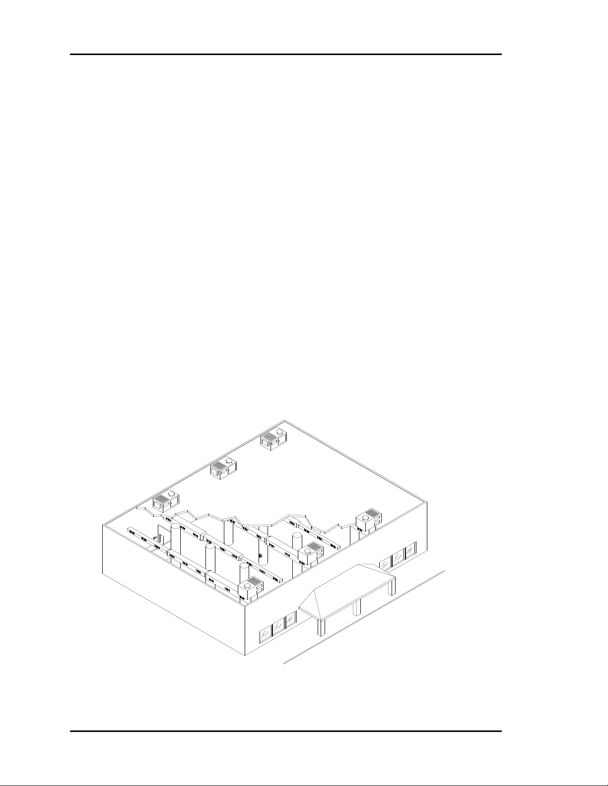
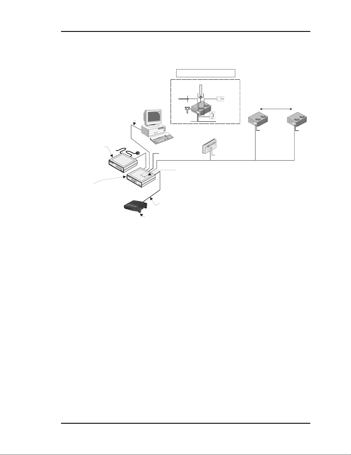
The Auto-Zone CV system is used in buildings which have multiple rooftop units and is
an excellent alternative over programmable thermostats. The CV system provides one
central location to monitor and program the controllers instead of having to program each
thermostat individually. The system has many features typically not found with
programmable thermostats such as: central operators interface, heating/cooling failure
alarm, change filter alarm, full energy saving economizer control, and holiday scheduling.
This gives the end user a very versatile constant volume control system at a price well
below a building automation system.
Below are a few of the typical building applications the CV system is commonly used for.
• Office Buildings • Retail Stores • Theaters
• Warehouses • Restaurants • Supermarkets
• Schools • Manufacturing • Houses of Worship
Figure 1-1: Typical Building for CV System
1-2 System Overview
Page 7
Auto-Zone CV & CV-EX Section 1
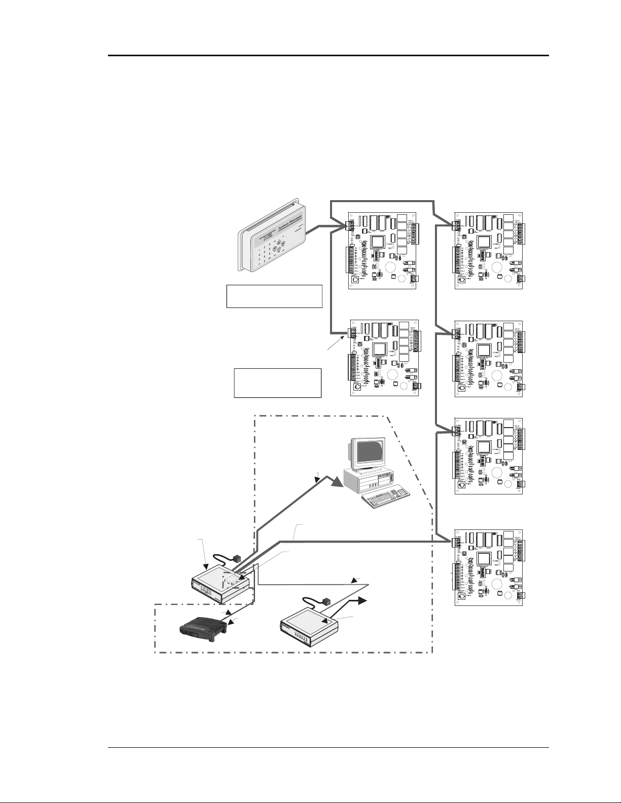
CV System Features
NOTE: * Only One Outside Air Sensor
is Required per CV Syste m
USB Cable To Computer
Optional Remote Link II
Connects to CommLink IV
And Provides Alarm Call-Outs
A Second Remote Link Is Required
If Connection To Job Site
Is Desired From Remote Computer
Remote Link II
(Option al)
CommLink IV
The CommLink IV Is
Required For All Systems.
The IP Module, Remote
Link II, And Computer Are
Optional On All Systems.
All Computers Require
Installation of Prism
Graphical User Interface
Software
Phone Cable
To Telephone
Wall Outlet Jack
CommLink IV
Single Loop
Computer
(Optional)
Ethernet Router
(By Others)
When IP Module
Option Is Used
Typical Constant Volume Unit
Supply
Air
Sensor
*
Outside
Air
Sensor
RS-485
Comm Loop
24VAC
RS-485
9600 Baud
Optional IP Module
Installs Into CommLink IV
And Provides
LAN And Internet Communications
With The Control System
Ethernet Cable To Router
Generic Al arm
Dirty F ilter Alarm
Shown
Economizer
(Actuator By Others)
Room Sensor
with Optional
Override & Adj.
24 VAC
24VAC
System Manager
CV Controllers
Up to 30 Units with Standard CV System
#1
24VAC
System Manager
#30
Local Loop
24VAC
Figure 1-2: Typical CV System
Below is a list of some of the many features available with the CV system.
• CV system supports up to thirty constant volume units. For systems with
more than thirty constant volume units, use the CV-EX system.
• System Manager is housed in an attractive, plastic enclosure suitable for
wall mounting in the space and can be connected anywhere in the
communications network.
• Complete modulating economizer control functions.
• CommLink IV interface included with the system. Provides connections
for computer and Remote Link II (modem) for on-site or remote
communications or connection for TCP/IP communications using the IP
Module. Remote Link II, IP Module & personal computer are optional.
• Trend Logging capability if connected to a personal computer with free
®
Prism™ Windows
-based software installed.
System Overview 1-3
Page 8

Section 1 Auto-Zone CV & CV-EX
CV-EX System Overview
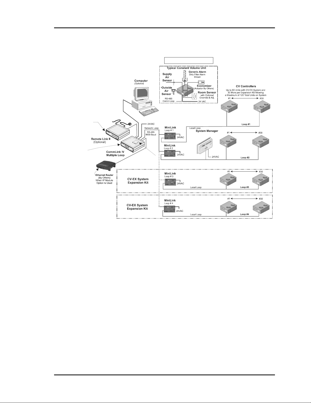
The Auto-Zone CV-EX system is used in buildings that because of their size or design
requirements have more than thirty rooftop units. Standard CV-EX systems can facilitate
up to sixty constant volume units. With the addition of a CV-EX Loop Expansion Kit, an
additional thirty units may be added to the CV-EX system. Two loop expansion kits can
be added to the CV-EX system bringing the maximum total system capability up to 120
units. The versatile CV-EX system provides one central location to monitor and program
the controllers instead of having to program individual thermostats. The system has many
features typically not found with programmable thermostats such as: central operators
interface, heating/cooling failure alarm, change filter alarm, full energy saving
economizer control, and holiday scheduling.
Below are a few of the typical applications the CV-EX system is commonly used for.
• Office Buildings • Retail Stores • Theaters
• Warehouses • Restaurants • Supermarkets
• Schools • Manufacturing • Houses of Worship
Figure 1-3: Typical Building for CV-EX System
1-4 System Overview
Page 9
Auto-Zone CV & CV-EX Section 1
CV-EX System Features
NOTE: * Only One Outside Air Sensor
is Required per CV-EX System
Phone Cable
To Tel epho ne
Optional Remote Link II
Connects to CommLink IV
And Provides Alarm Call-Outs
A Second Remote Link Is Required
If Connection To Job Site
Is Desired From Remote Computer
CommLink IV
The CommLink IV Is
Required For All Systems.
The IP Module, Remote
Link II, And Computer Are
Optional On All System s.
All Computers Require
Installation of Prism
Graphical User Interface
Software
Wall Outlet Jack
Optional IP Module
Installs Into CommLink IV
And Provides LAN And
Internet Comm unications
With The Con trol System
Figure 1-4: Typical CV-EX System
Below is a list of some of the many features available with the CV-EX system.
• CV-EX system supports from thirty-one to one hundred twenty constant
volume units. For systems with thirty or less constant volume units, use
the CV system.
• System Manager is housed in an attractive, plastic enclosure suitable for
wall mounting in the space and can be connected anywhere in the
communications network.
• Complete modulating economizer control functions.
• CommLink IV interface included with the system. Provides connections
for computer and Remote Link II (modem) for on site or remote
communications or connection for TCP/IP network communications using
IP Module. Remote Link II, IP Module, & personal computer are optional.
• Trend Logging capability if connected to a personal computer with free
Prism™ Windows®-based software installed.
System Overview 1-5
Page 10

Section 1 Auto-Zone CV & CV-EX
Index
120 Units............................................... 4
CommLink IV
Described ...................................... 3, 5
Conventions .......................................... 1
CV System
Features ............................................. 3
Overview........................................... 2
CV Units
< 30 ................................................... 3
> 30 ................................................... 4
60....................................................... 4
CV-EX Loop Expansion Kit................. 4
CV-EX System...................................... 3
Features ............................................. 5
Overview........................................... 4
Features
CV System ........................................ 3
CV-EX System.................................. 5
IP Module.......................................... 3, 5
Modem
Described ...................................... 3, 5
Network Communications ................ 3, 5
Overview
CV System ........................................ 2
CV-EX System.................................. 4
Prism ................................................. 3, 5
Remote Link II
Described ...................................... 3, 5
Rooftop Units
< 30 ................................................... 3
> 30 ................................................... 4
System Manager
Described ...................................... 3, 5
Trend Logging................................... 3, 5
Void Warranties .................................... 1
Warranties ............................................. 1
1-6 System Overview
Page 11

Section 2
Table of Contents
Tips Before Beginning Installation.................................. 1
Systems Overview ........................................................... 2
CV System .......................................................................................................................2
CV-EX System.................................................................................................................3
Communications Loop ..................................................... 4
CV & CV-EX Communications Loops ...........................................................................4
Communications Loop Wiring Overview........................................................................5
CV Controller ...................................................................8
CV Controller Wiring ......................................................................................................9
CV Controller Addressing .............................................................................................11
CV System Sensors........................................................ 12
Room Sensor..................................................................................................................12
Supply Air Temperature Sensor.....................................................................................14
Outside Air Temperature Sensor ...................................................................................15
CommLink IV Interface.................................................. 16
Optional IP Module Kit .................................................................................................16
Optional Remote Link II................................................................................................17
CommLink IV Wiring....................................................................................................18
CommLink IV DIP Switch Setting ................................................................................19
Installing the CommLink IV ..........................................................................................21
System Manager ............................................................ 22
System Manager Wiring ................................................................................................23
MiniLink Interface.......................................................... 24
MiniLink Interface Wiring.............................................................................................25
CV & CV-EX Worksheet ..............................................................................................26
Index .............................................................................. 27
Installation and Wiring
Page 12

Section 2
Table of Figures
Figure 2-1: CV System Overview .................................................................................2
Figure 2-2: CV-EX System Overview...........................................................................3
Figure 2-3: CV Communication Loop Wiring, Daisy-Chain Configuration.................5
Figure 2-4: CV-EX Communication Loop Wiring, Daisy-Chain Configuration ..........6
Figure 2-5: CV Controller with Backplate - Components.............................................8
Figure 2-6: Constant Volume Controller Wiring...........................................................9
Figure 2-7: CV Controller Address Switch Setting.....................................................11
Figure 2-8: Room Sensor Installation..........................................................................12
Figure 2-9: Room Sensor Wiring ................................................................................13
Figure 2-10: Supply Air Temperature Sensor Installation ..........................................14
Figure 2-11: Outside Air Temperature Sensor............................................................15
Figure 2-12: CommLink IV Interface Wiring & Jumper Setting................................18
Figure 2-13: CommLink IV DIP Switch Setting ........................................................19
Figure 2-14: CommLink IV to MiniLink Wiring .......................................................20
Figure 2-15: CommLink IV to CV Controller Wiring................................................20
Figure 2-16: System Manager Dimensional Data.......................................................22
Figure 2-17: System Manager Wiring.........................................................................23
Figure 2-18: MiniLink Interface Overview.................................................................24
Figure 2-19: MiniLink Interface Wiring.....................................................................25
Installation and Wiring
Page 13

Auto-Zone CV & CV-EX Section 2
Tips Before Beginning
Installation
Take a few moments to review the following before beginning installation of the AutoZone CV and CV-EX systems.
• Familiarize yourself with all system components and review all documentation. Pay
special attention to “Cautions” and “Warnings” since these may keep you from
experiencing unnecessary problems.
• Before installing each controller, be sure to tag it with its appropriate location. It is
also best to set the controller address switches before mounting. Use the CV and CVEX Address Worksheet included at the end of this section and in the CV and CV-EX
submittal package to list all CV unit locations. This will assist you greatly when
setting up the system and later for any necessary system troubleshooting.
• Be sure and install all wiring according to local, state, and national codes.
• Pay close attention to communication wiring since the most common mistakes are
made in this area. Polarity is the most important rule. Make notes on your wiring
diagrams as to which color wire you will be using on each terminal.
• When in doubt - ask! Contact your local Auto-Zone distributor if you have any
questions. The only dumb questions are the ones you don’t ask.
• Remember - each electronic device contains only one puff of smoke. If you release it,
you have voided the warranty! So please be careful and pay attention.
Installation and Wiring 2-1
Page 14
Section 2 Auto-Zone CV & CV-EX
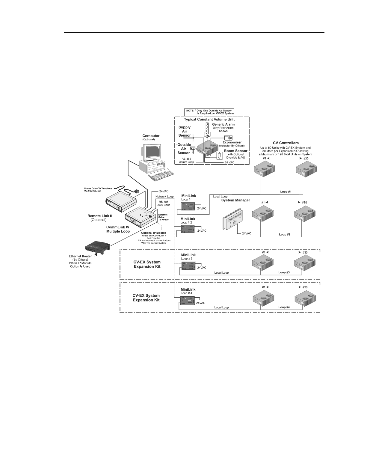
Systems Overview
CV System
Figure 2-1: CV System Overview
2-2 Installation and Wiring
Page 15
Auto-Zone CV & CV-EX Section 2
CV-EX System
Figure 2-2: CV-EX System Overview
Installation and Wiring 2-3
Page 16

Section 2 Auto-Zone CV & CV-EX
Communications Loop
The Communications Loop for both the CV and CV-EX systems is two-wire shielded
RS-485. The loop is best connected in daisy-chain configuration, meaning the loop is
connected from one controller to another. It is not necessary to sequentially address the
CV Controllers in relation to their location on the loop. Cable must be Belden No. 82760
or equivalent.
Tip: Incorrect wiring of the communications loop is the most common mistake made
during installation. Before beginning installation, write down the wire color used
on each terminal connection and consistently maintain that color code. It is
recommended that a continuous wire run be made between devices. Anytime a
splice is made in the cable, you increase your chance of problems.
Caution: Make sure when you are inserting wires into the terminal blocks that
strands of wire do not stick out and touch the next terminal. This could
cause a short or erratic operation.
CV & CV-EX Communications Loops
The CV and CV-EX communications loops are different in one respect. The CV has only
one communication loop while the CV-EX has two. On the CV system, all of the CV
controllers are daisy-chained together and tied into the CommLink on one end of the
loop. Each controller is assigned a numbered address by setting the DIP switch on each
one. See Figure 2-3 for the CV system communication wiring diagram. This is the only
communications loop required on the CV system.
For the CV-EX system communications wiring, see Figure 2-4. As is shown in the
diagram, all of the CV Controllers are daisy-chained together just like the CV system.
This is referred to as the “Local Loop.” This local communications loop is then tied into
the MiniLink communication interface to the terminals marked Local Loop instead of the
CommLink. On the CV-EX system, all of the MiniLinks terminals marked “Network
Loop” are then daisy-chained to each other and on one end to the CommLink
communication terminals. Each MiniLink is then addressed with a different number by
setting its DIP switch in similar fashion to the CV controllers.
2-4 Installation and Wiring
Page 17
Auto-Zone CV & CV-EX Section 2
Communications Loop Wiring Overview
The daisy-chain is the best method for running a communications loop since there is only
one starting point and one ending point for each of the communications loops. See Figure
2-3 and Figure 2-4. The general concept is the same for both the CV and the CV-EX.
CV ControllerCV Controller
System Manager
The System Manager Can Be
Connected Anywhere
On The Loop
CV Controller
CV Controller
CommLink IV
The CommLink IV Is Required For
All Systems. The IP Module,
Remote Link II, And Computer Are
Optional On All Systems. All
Computers Require Installation of
Prism Graphical User Interface
Software
Ethernet Cable To Router
All Components Shown Inside This Box Are Optional
End Of Loop
The Comm Loop
Routing Does Not
Have To Follow
The Board Address Sequence
USB Cable To Computer
Loop Start
Optional IP Module
Installs Into CommLink IV
And Provides LAN And Internet
Communications
With The Control System
Ethernet Router
(By Others)
When IP Module
Option Is Used
Computer
(Optional)
Comm Loop
RS-485
9600 Baud
Serial Cable To Remote Link
Phone Cable To Telephone
Wall Outlet Jack
Optional Re mote Link I I
Connects to CommLink IV And
Provides Alarm Call-Outs. A
Second Remote Link Is Required If
Connection To Job Site Is Desired
From Remote Computer.
CV Controller
CV Controller
Figure 2-3: CV Communication Loop Wiring, Daisy-Chain Configuration
Installation and Wiring 2-5
Page 18

Section 2 Auto-Zone CV & CV-EX
CV ControllerCV Controller
System Manager
The System Manager Can Be
Connected Anywhere
On The Local Loop
End Of Local Loop
The Comm Loop
Routing Does Not
Have To Follow
The Board Address Sequence
CV Controller
CV Controller
CommLink IV
The CommLink IV Is Required For
All Systems. The IP Module,
Remote Link II, And Computer Are
Optional On All Systems. All
Computers Require Installation of
Prism Graphical User Interface
Software
Ethernet Cable To Router
All Components Shown Inside This Box Are Optional
USB Cable To Computer
Ethernet Router
(By Others)
When IP Module
Option Is Used
Network Loop Start
Optional IP Module
Installs Into CommLink IV And
Provides LAN And Internet
Communications
With The Control System
Remote Link Is Required If Connection To
Job Site Is Desired From Remote Computer.
Computer
(Optional)
Serial Cable To Remote Link
Phone Cable To Telephone
Wall Outlet Jack
Optional Remote Link II
Connects to CommLink IV And
Provides Alarm Call-Outs. A Second
Connect To
Network Loop
Connection On
Next MiniLink
Network Loop
RS-485
19200 Baud
Local Loop
RS-485
9600 Baud
MiniLink
Local Loop Start
CV Controller
CV Controller
Figure 2-4: CV-EX Communication Loop Wiring, Daisy-Chain Configuration
2-6 Installation and Wiring
Page 19

Auto-Zone CV & CV-EX Section 2
Even though the daisy-chain configuration is preferred, the star configuration can also be
used for the CV or CV-EX systems. If required, a combination of the two can also be
used. Remember, the best communications loop wiring scheme is the one that utilizes the
minimum number of ends while using the shortest wiring path.
Note: The communication loops do not have to follow the controller or MiniLink
address sequence.
Caution: If the communications loop is not installed in conduit, be careful to
position the cable away from high noise devices like fluorescent lights,
transformers, variable frequency drives, radio or TV transmitting
equipment, furnace ignition system wires, etc. Conduit is not required
for communication loop wiring unless required by local codes.
Installation and Wiring 2-7
Page 20
Section 2 Auto-Zone CV & CV-EX
s
Typical
CV Controller
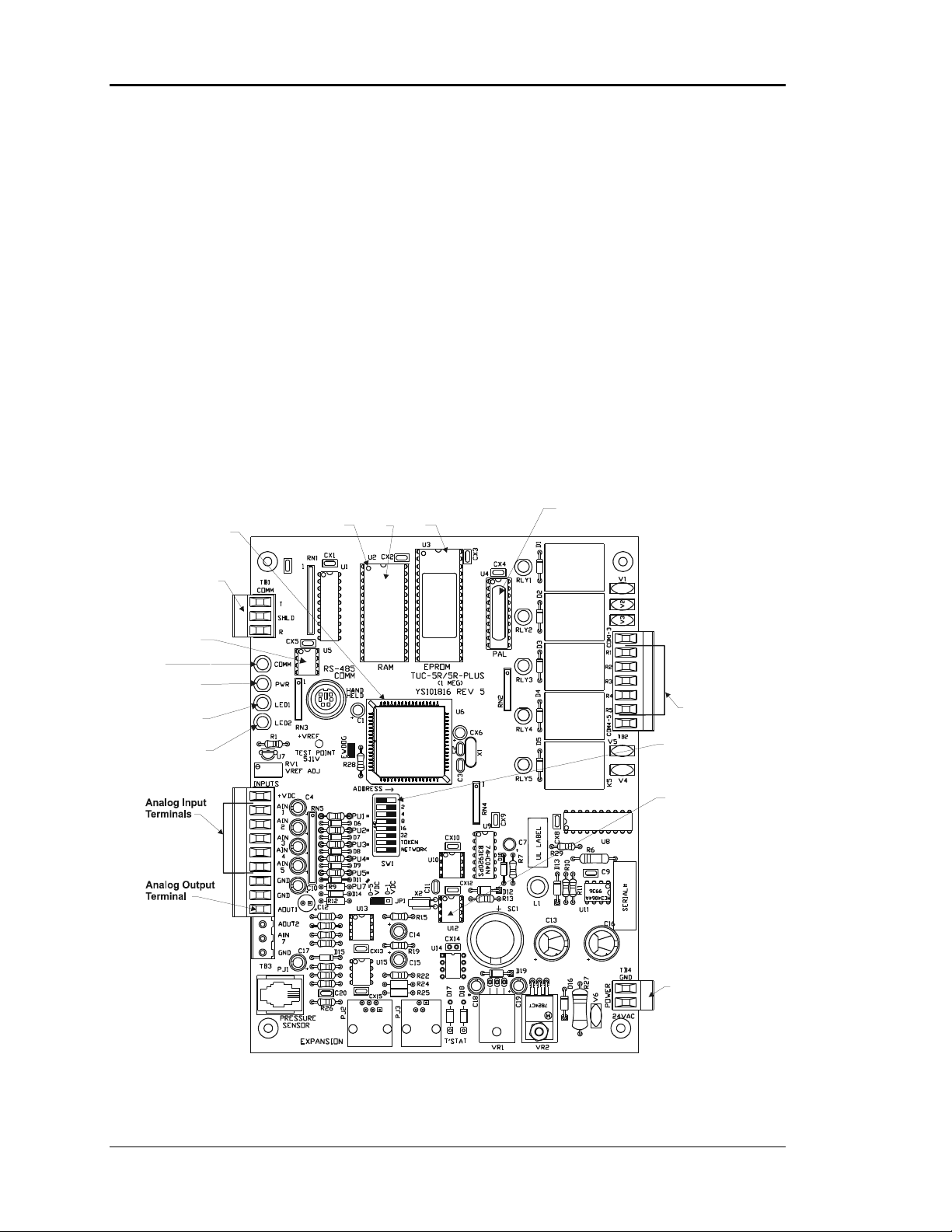
The CV Controller (Constant Volume Controller) may be installed in any convenient
protected location. Observe the recommended environmental limitations for the CV
Controller. It should not be mounted in locations subject to extreme low or high
temperatures (below 20° F or above 140° F) or in damp or wet environments (maximum
of 90% RH). If it is to be mounted outdoors, it must be enclosed in a weather-tight
enclosure.
The CV Controller may be mounted without removing the controller from the mounting
plate. The unit is mounted by securing four (4) screws through the mounting holes in the
mounting backplate. Select the correct screws or other fasteners for the type of mounting
material being utilized.
CPU
Chip
Pin 1
Indicator
RAM
Chip
EPROM
Chip
PAL
Chip
RS-485
Communications
Terminal Block
RS-485
Communications
Driver Chip
Communications
LED
Power LED
Diagnostic Blink
Code LED 1
Diagnostic Blink
Code LED 2
Relay Output
Ter mi nal s
Address Switch
Real Time
Clock Chip
24 VAC
Power Input
Termi nal
Figure 2-5: CV Controller with Backplate - Components
2-8 Installation and Wiring
Page 21
Auto-Zone CV & CV-EX Section 2
g
g
g
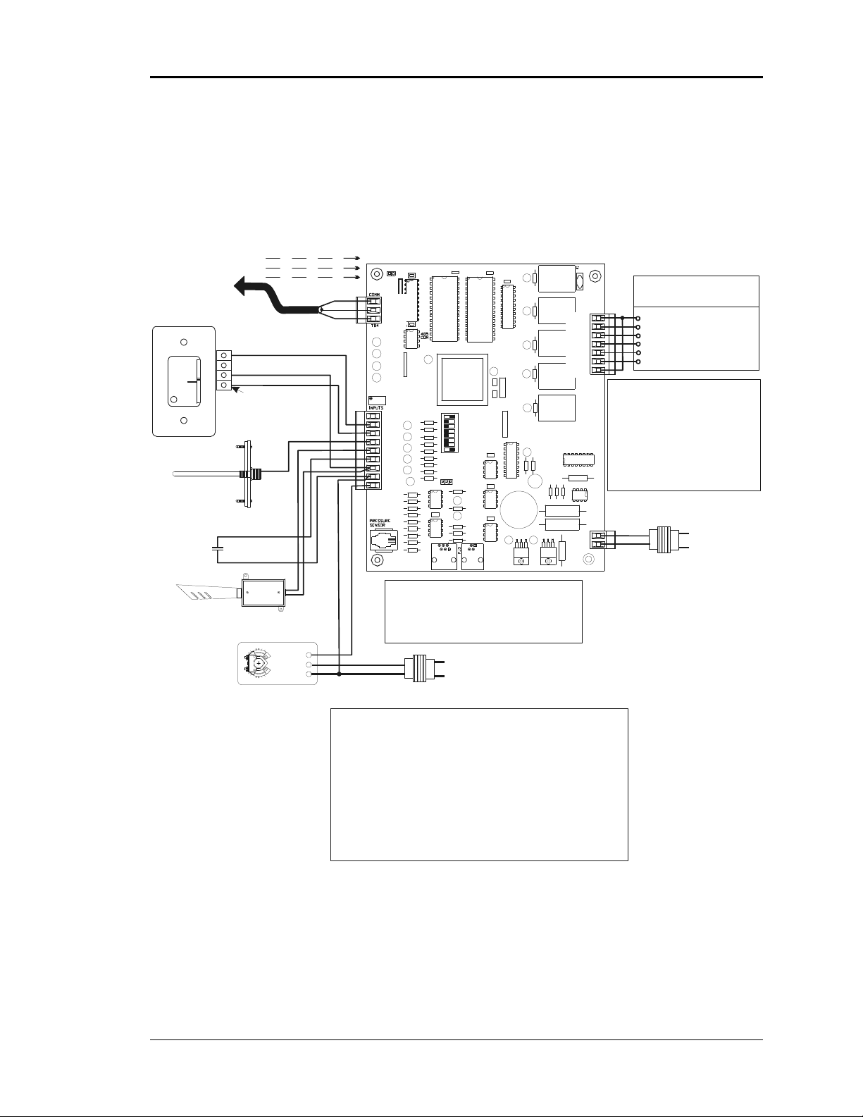
CV Controller Wiring
Connect To
Next Controller
MiniLink On
Local Loop
Room Sensor
NORMAL
OVR
Mount In HVAC
Tem p. Sens or
And/Or
W
A
R
M
E
R
C
O
O
L
E
R
Discharge
Air Temp.
Sensor
Unit Supply
Air Duct
Switch Supplied
By Others
Auxiliary Alarm
Outside Air
(See Note 4)
All Comm Loop Wiring Is
Straight Thru
T
T
SH
SH
R
R
Local Loop
RS-485
9600 Baud
TMP
GND
AUX
Connection To
AUX Terminal is Reqd
Only When Sensor
Is Specified With
Slide Adjust Option
Input
Y 3
+ 2
COM 1
Economizer
Actuator
(Belimo Shown)
Consult Factory For
Other Manufacturers
Wiring Connections
T
T
SH
SH
R
R
T
SHLD
R
+VDC
AIN 1
AIN 2
AIN 3
AIN 4
AIN 5
GND
GND
AOUT
TB3
EXPANSION T'STAT
Caution:
When Wiring The CV Controller Be Sure To
Disconnect All Communication Loop Wiring
From The CV Controller Before Removing Power
From The CV Controller. Reconnect Power And
Then Reconnect Communication Loop Wiring.
24VAC
GND
See Note 1 & 2
Notes:
1.)24 VAC Must Be Connected So
That All Ground Wires Remain
Common.
2.)All Wiring To Be In Accordance
With Local And National
Electrical Codes And
Specifications.
3.)All Communication Wiring To
Be 2 Conductor Twisted Pair
With Shield. Use Belden
#82760 Or Equivalent.
CV Controller
1
2
4
8
16
32
TOKEN
NETWORK
Line Voltage
RELAY
OUTPUTS
COM1-3
R1
R2
R3
R4
R5
COM4-5
GND
24VAC
4.)Only One Outside Air
Sensor Is Required Per
System. It May Be
Connected To Any CV
Controller On The System.
If The Wetbulb Module Is
Used, The OA Sensor Must
Be Connected To The
Wetbulb Module.
Constant Volume
Unit Connections
R (24VAC)
G (Fan-On/Off)
Wx or Yx (Htg or Clg Stage x)
Wx or Yx (Ht
Wx or Yx (Ht
Wx or Yx (Ht
TB2
Note:
Up To 4 Stages Of Heating Or
Cooling Or Any Combination Of Each
Is Allow ed And Programma ble Via
The System Manager or Computer
Front End Software. If The Unit Has
Heat, Heating Stages Must Be
Connected To The First Outputs in
Consecutive Order And Cooling
Stages To The Remaining Outputs In
Consecutive Order.
Required VA For Transforme r
Each CV Controller = 20VA Min.
TB1
GND
24VAC
See Note 1 & 2
or Clg Stage x)
or Clg Stage x)
or Clg Stage x)
Line Voltage
Figure 2-6: Constant Volume Controller Wiring
Installation and Wiring 2-9
Page 22
Section 2 Auto-Zone CV & CV-EX
Warning: Polarity is very important when connecting power to the controllers!
The grounded side of the control transformer must be connected to the terminal
labeled GND on the CV Controller. If a single transformer is used to power more
than one CV Controller, you must connect GND-to-GND and 24VAC-to-24VAC on
each CV controller. Failure to observe polarity will result in damage to one or more
components in your system.
Warning: Use extreme care not to damage any of the electronic components
while mounting the backplate. Mark the holes and then remove the CV Controller
from the backplate before drilling.
Do not allow metal shavings to fall onto the circuit boards.
The Constant Volume Controller requires the following electrical connections:
18-Gauge minimum unless otherwise noted.
-24 VAC Supply Voltage.......................................................................... 2 Conductors
-Communications Loop ...................................... 2 Conductor twisted pair with shield
(Belden #82760 or equivalent)
-Supply Air Temperature Sensor ........................................ (24 ga. Min.) 2 Conductors
-Room Air Temperature Sensor...........(24 ga. Min.) 2 Conductors for standard sensor
3 Conductors for sensors with setpoint adjustment
-Outside Air Temperature Sensor ....................................... (24 ga. Min.) 2 Conductors
-HVAC Unit Control Wiring .....................................................................R - Common
G - Fan
Heat/Cool Stage 1
Heat/Cool Stage 2
Heat/Cool Stage 3
Heat/Cool Stage 4
Tip: After making all electrical connections, we recommend that you unplug all
terminal blocks on the CV Controller until you are ready to begin the checkout
procedure. This may help to prevent damage if wiring errors occur elsewhere in
the system during installation or start-up.
2-10 Installation and Wiring
Page 23
Auto-Zone CV & CV-EX Section 2
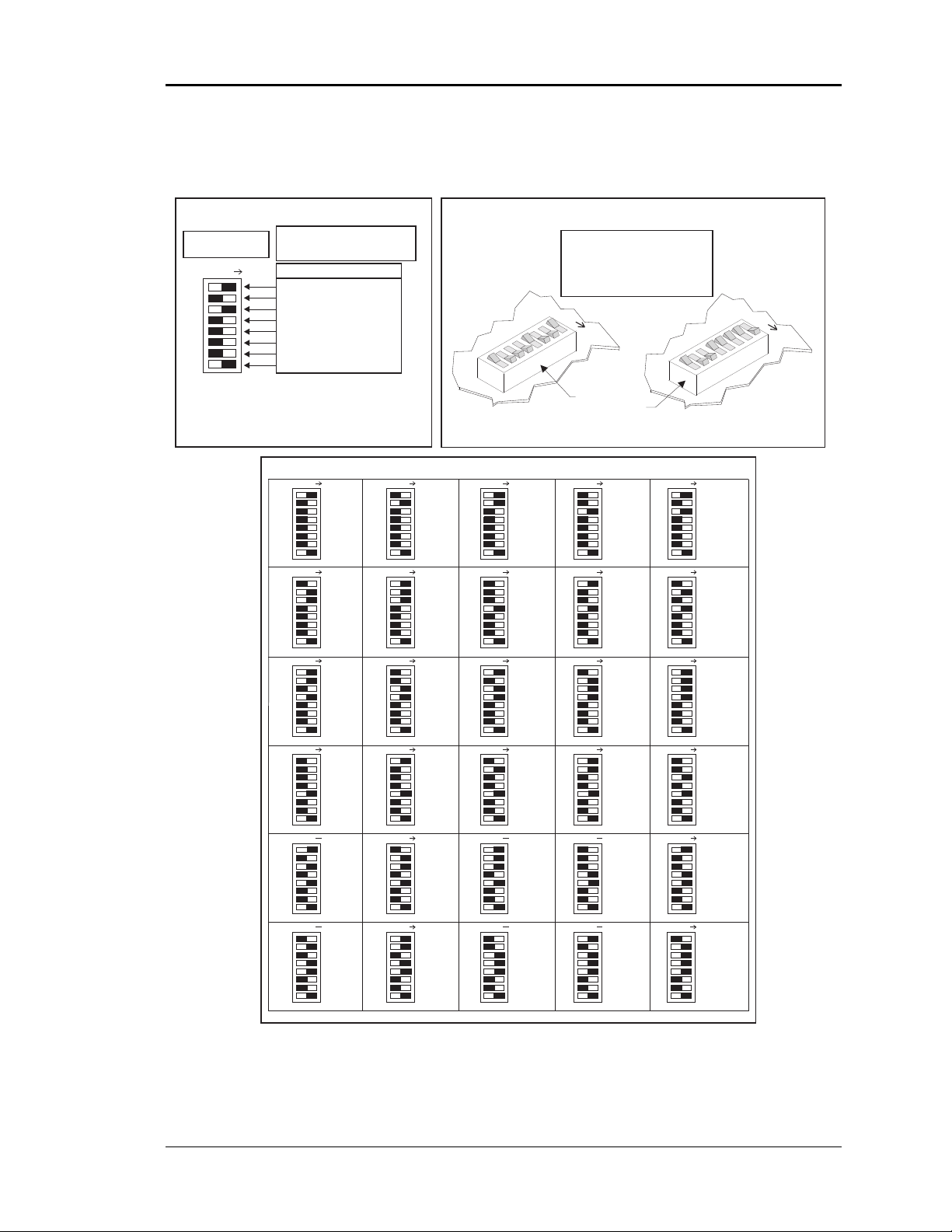
CV Controller Addressing
CV Controller Address Switch SettingCV Controller Address Switch Values
Switch Shown Is
Set For Address 5
ADDRESS ADD
Note:
1.) Ignore Any Markings On The Switch Body.
2.) Use The Address Charts Below Or Address Switch
3.) Power To Controller Must Be Turned Off And
SW1
Value Table Above To Determine Correct Switch Setting.
Back On In Order For Switch Settings To Take Effect.
Address Switch Values Are Not
Labeled On The CV Controller
Use The Table Below
Address Switch Values
1
2
4
8
16
32 (Always OFF- Not Used)
TOKEN (Always OFF)
NETWORK (Always ON)
SW1
Address Switch Shown Is
Set For Address 9
Address Switch Values Are
Added Together When The
Rocker Is Pushed Down In
The Direction Of The “ADDRESS
ADD” Arrow Marked On The CV
Controller Circuit Board
ADDRESS ADD
Controller
Address Switch
ADDRESS ADD
SW1
Address Switch Shown Is
Set For Address 30
ADDRESS ADD
SW1
ADDRESS ADD ADDRESS ADD ADDRESS ADD ADDRESS ADD ADDRESS ADD
SW1 SW1 SW1 SW1 SW1
ADDRESS ADD ADDRESS ADD ADDRESS ADD ADDRESS ADD ADDRESS ADD
SW1 SW1 SW1 SW1 SW1
ADDRESS ADD ADDRESS ADD ADDRESS ADD ADDRESS ADD ADDRESS ADD
SW1 SW1 SW1 SW1 SW1
ADDRESS ADD ADDRESS ADD ADDRESS ADD ADDRESS ADD ADDRESS ADD
SW1 SW1 SW1 SW1 SW1
ADDRESS ADD ADDRESS ADD ADDRESS ADD ADDRESS ADD ADDRESS ADD
ADDRESS ADD ADDRESS ADD ADDRESS ADD ADDRESS ADD
1
6
11
16
21
2
SW1 SW1 SW1 SW1
7
12
17
22
3
8
13
18
23
4
9
14
19
24
Address Switch Setting Chart For CV Controllers
5
10
15
20
25
26
SW1 SW1 SW1 SW1 SW1
27
28
29 30
Figure 2-7: CV Controller Address Switch Setting
Installation and Wiring 2-11
Page 24
Section 2 Auto-Zone CV & CV-EX
CV System Sensors
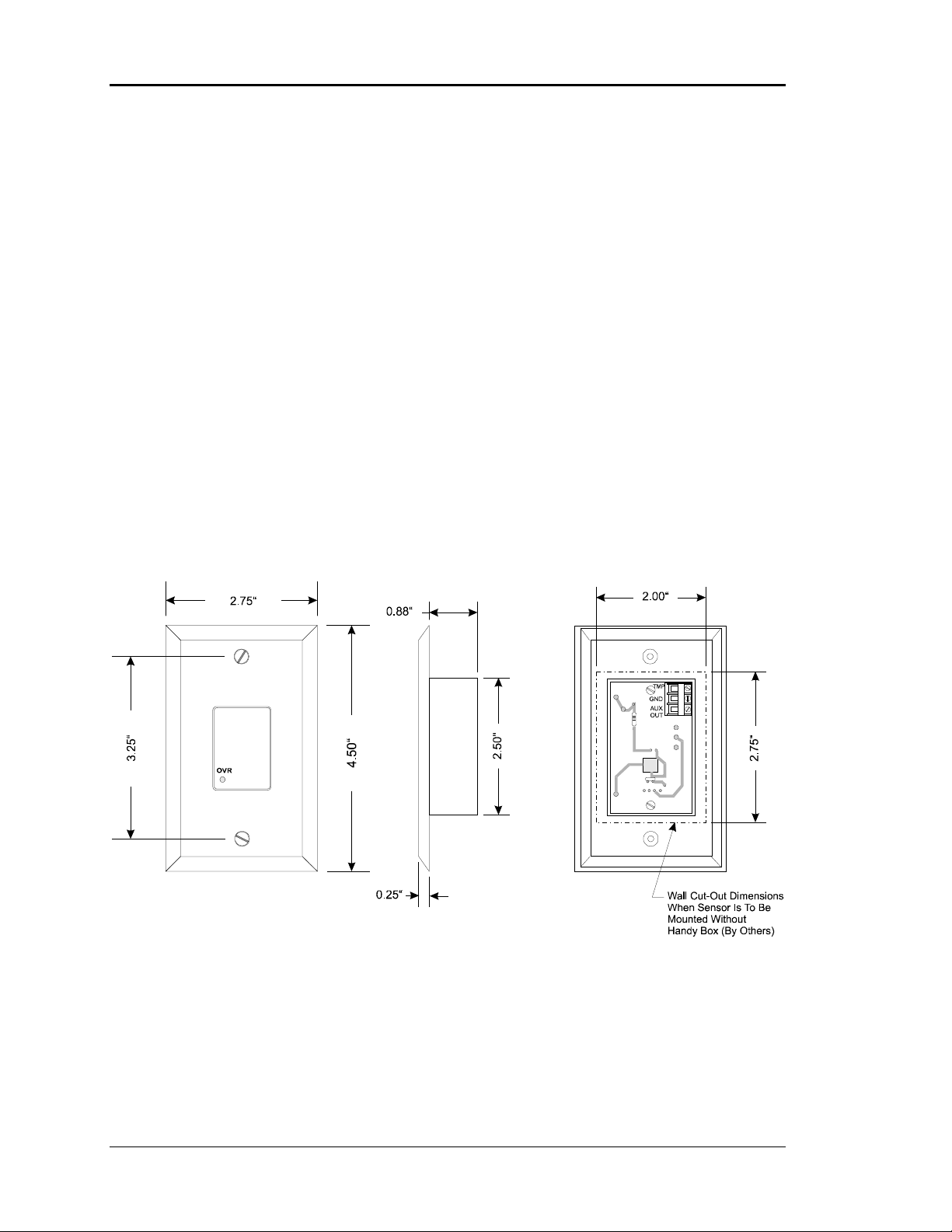
Room Sensor
The Room Sensor uses a patented flush-mount design to isolate the temperature sensing
element from the housing which mounts flush with the wall surface.
Room Sensors should be located on an inside wall away from direct sunlight or heat
producing equipment such as computers, copiers, etc. Such devices can adversely affect
the accuracy of the sensor. Although the sensor eliminates most of the effects of thermal
coupling to the walls, try to avoid walls which retain large amounts of thermal energy
(such as marble or steel). Walls containing either cold or warm air currents should also be
avoided whenever possible. Avoid locating the sensor in dead air areas of a room. This
will result in slow response to temperature changes in the space.
Figure 2-8: Room Sensor Installation
Mount the sensor approximately 50-60 inches from the floor for best results. The Room
Sensor is designed to mount vertically in a standard 2-by-4-inch electrical box. The
sensor may be mounted directly into the drywall where electrical codes do not require
low-voltage wiring to be enclosed in conduit. A template is supplied with the sensor to
facilitate cutting a hole of the correct size.
2-12 Installation and Wiring
Page 25
Auto-Zone CV & CV-EX Section 2
V
A
A
AINAINAINA
Tip: Be careful when cutting the hole for the sensor or the plastic bezel of the sensor
may not completely cover the opening.
Tip: If sensors must be installed on walls that are solid and cannot be penetrated,
surface-mounted boxes and raceway can be purchased from your local electrical
distributor.
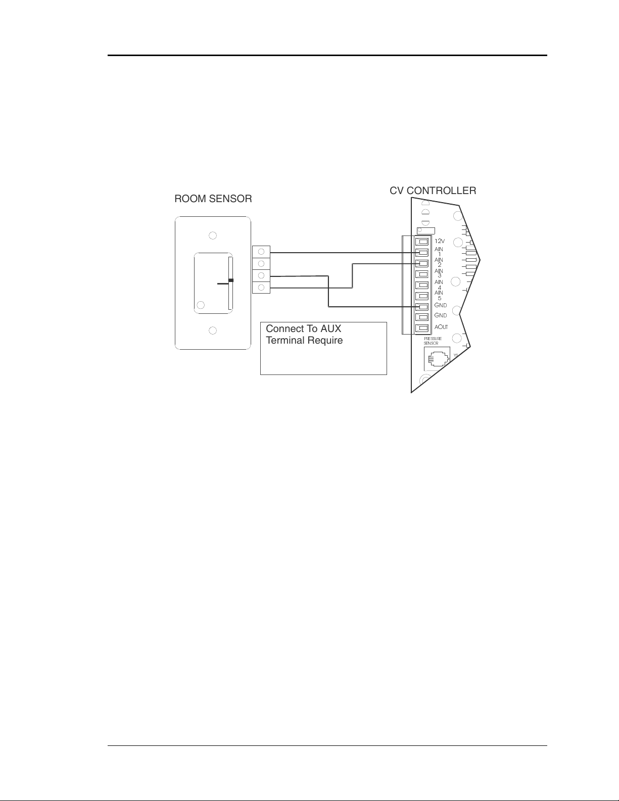
ROOM SENSOR
CV CONTROLLER
PRESSURE
SENSOR
12
IN
1
2
3
4
IN
5
GND
GND
OUT
YS
OVR
W
A
R
M
E
R
C
O
O
L
E
R
TMP
GND
AUX
Connect To AUX
Terminal Required Only
When Sensor Is Specified
With Slide Adjust Option
Figure 2-9: Room Sensor Wiring
Connect the terminal labeled GND on the room sensor to the terminal labeled GND on
the CV Controller terminal block TB3. Connect the terminal labeled TMP on the room
sensor to the terminal labeled AIN1 on the CV Controller terminal block. If the room
sensor has a setpoint adjust slider, connect the sensor terminal labeled AUX to the CV
Controller AIN2 terminal block.
Installation and Wiring 2-13
Page 26
Section 2 Auto-Zone CV & CV-EX
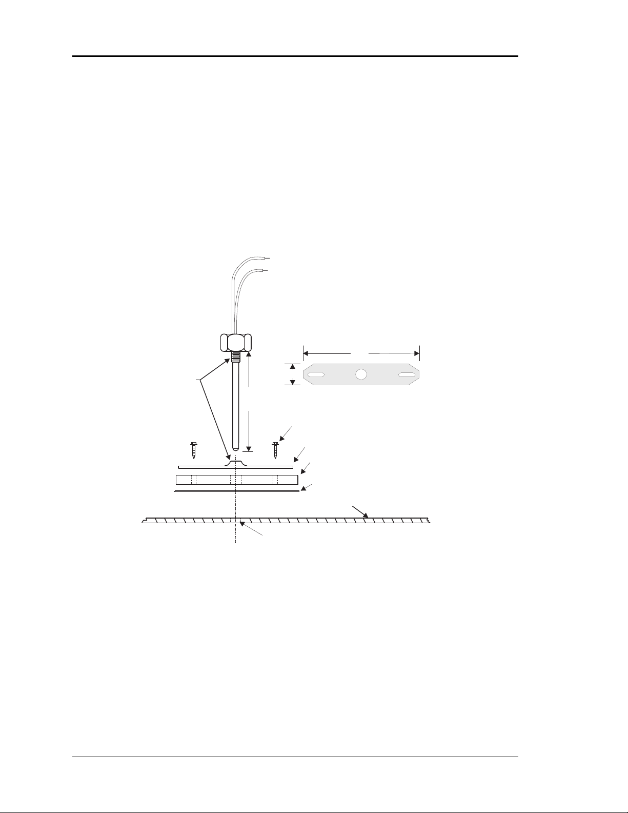
Supply Air Temperature Sensor
The Supply Air Temperature Sensor should be located as close to the rooftop unit
discharge as possible for the best response. Locate the sensor in the center of the widest
part of the duct. Use the supplied template and a 5/16" drill to make a hole for the sensor.
Install the gasket over the probe and mount securely to the duct using the supplied sheet
metal screws. Be sure the gasket is compressed to provide an air-tight seal. For best
accuracy, apply insulation on the outside of the duct, over the sensor. This will help
prevent thermal gradients from affecting the sensor.
Leads Are Non-polarized.
Butt Splice Leads To24Gauge
Wire Minimum. Connect Leads
To "AnalogIn"And "Ground"
At Controller.
4.0"
Thread
Together
5-1/2" (OE230)
11-1/2" (OE231)
3/4"
Mounting Plate
1/4" HexHead Sheet MetalScrews
Mounting Plate
Gasket
AdhesiveBacked Drill Guide
MountingTemplate
Duct Work
Drill 5/16"Hole In Ductwork For Probe
Figure 2-10: Supply Air Temperature Sensor Installation
2-14 Installation and Wiring
Page 27
Auto-Zone CV & CV-EX Section 2
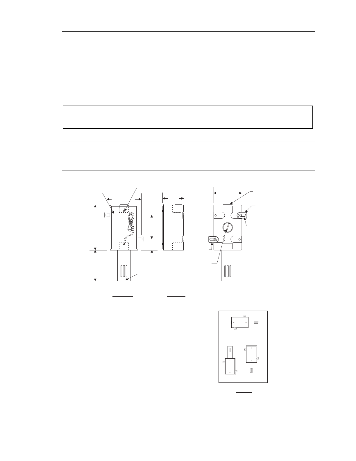
Outside Air Temperature Sensor
The Outside Air Temperature Sensor must be located where it will not be affected by
direct sun or heat-producing equipment. Mounting under the eave of a roof is often a
good choice.
Caution: Complaints of inaccurate outside sensor readings are very common and
can almost always be shown to be the result of poor sensor location.
Note: All sensors utilize the same type thermistor sensor element. For troubleshooting
sensor problems, refer to temperature sensor resetting instructions in Section 3
of this manual.
Gasketed Cover
CAUTION!
See Note3
3.00”
Cover
Mounting
Screw - Typ.
2.30”
2.70”
Closure Plug
CAUTION!
See Note 2
0.21" Dia. x 0.73
Lg. Slot - Typ.
Incorrect
Postion
Mounting Tab
& Screws - Typ.
Correct
4.50”
3.00”
Front View Side View
Notes:
1.)The Outside Air Sensor Must Be
Mounted In A Vertical Position As
Shown (Sensor Tube Pointing
Water Must Not Be
Down).
Allowed To Stand In Sensor
Tube. Rainwater Will Damage
Sensor.
Sensor Must Be Located
Where It Will Not Be Affected By
Direct Sunlight Or Heat Producing
Equipment. If Possible Mount Under
Roof Eave Or Similar Protected
Location. If Sensor Is Not Located
As Specified, Erroneous Outside Air
Tem perature Readings Will Result.
2.25”
1.13”
Sensor Tube
CAUTION!
See Note 1
2.)Unused Conduit Opening(s) Must
Have Closure Plugs Installed And Must
Be Coated with Sealing Compound To
Provide Raintight Seal. Water Can
Damage Sensor!
3.)Gasket Must Be Installed Under Cover
Plate To Provide Raintight Seal.
Rainwater Can Damage Sensor!
4.)All Wiring To Be In Accordance With
Local And National Electrical Codes
And Specifications.
Mounting Tab
& Screw - Typ.
Closure Plug
CAUTION!
See Note 2
Back View
See Note #1
Incorrect
Sensor Mounting
Figure 2-11: Outside Air Temperature Sensor
Installation and Wiring 2-15
Page 28
Section 2 Auto-Zone CV & CV-EX
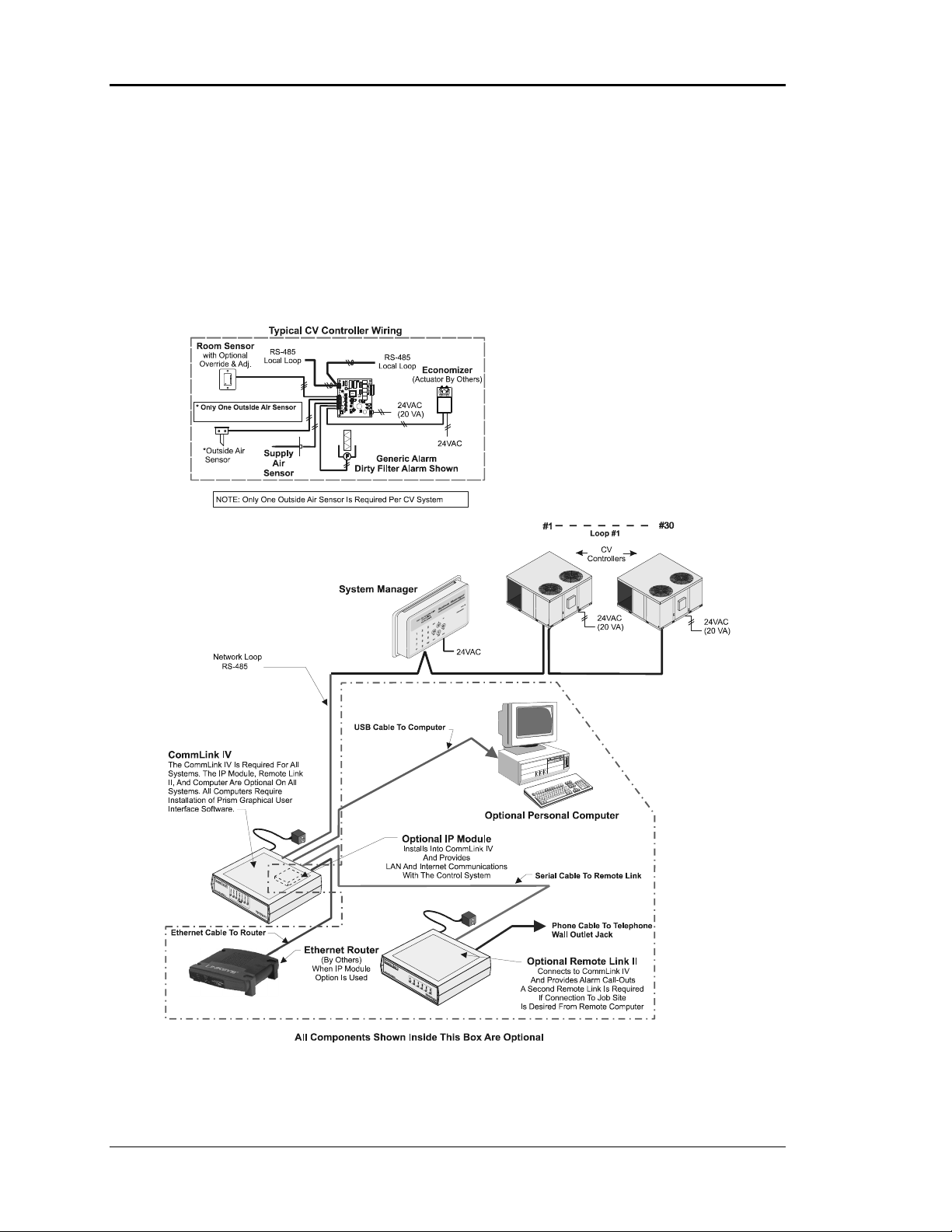
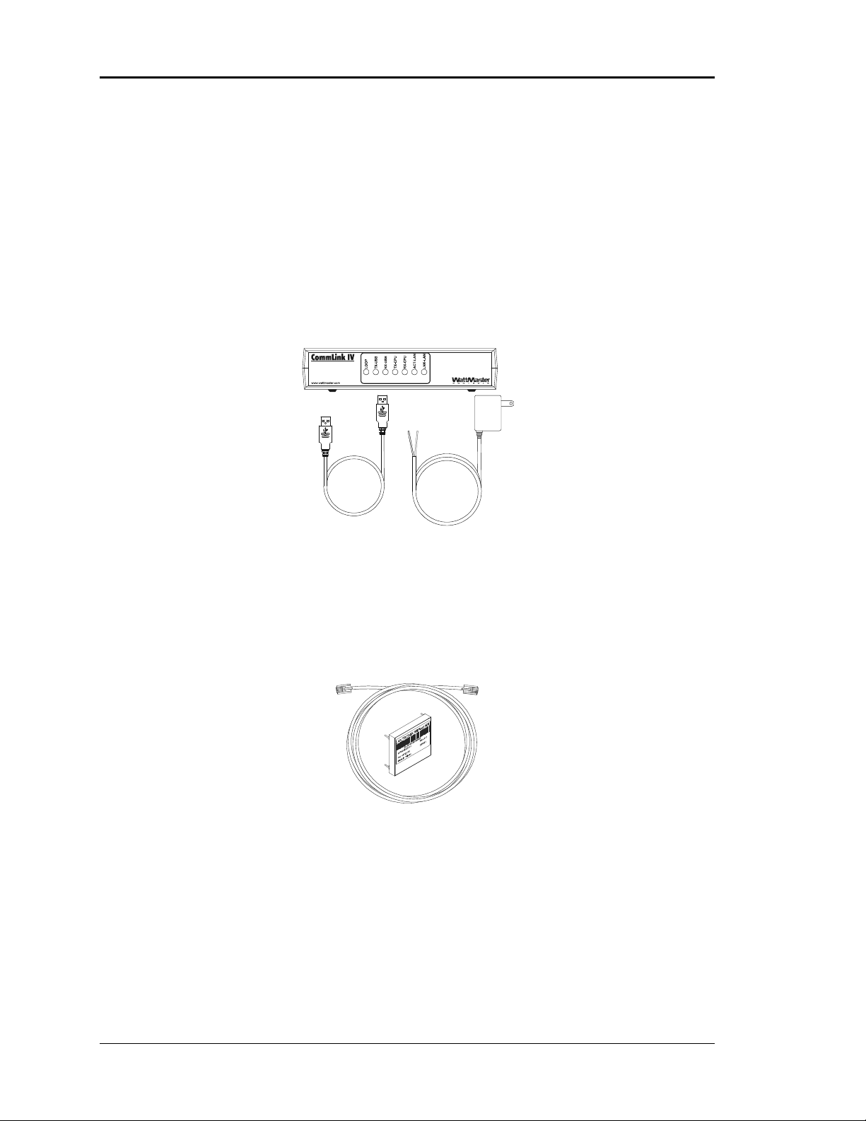
CommLink IV Interface
The CommLink IV Interface is used to transfer communications between controllers on
your control system loops. It can also be used as an interface for connection of a computer
to your system. The CommLink IV provides communication with any controller on the
control system through a computer that is running Prism software, or it can be used to
communicate with most controllers by using only the System Manager. For remote
communications, an IP Module Kit can be installed for LAN and Internet connections, or
a Remote Link II can be connected for dial-up connections.
STATUS
Optional IP Module Kit
The IP Module Kit, when installed and configured in the CommLink IV, provides
TCP/IP Internet and/or intranet connection for Ethernet networked computer systems
allowing them to communicate with your control system.
The OE415-02 IP Module Kit consists of the IP Module and a 10-foot-long CAT5
Ethernet crossover cable. Using standard TCP/IP Protocol, with WattMaster’s Prism
software, you are able to monitor and configure your controllers without a modem or a
direct connection from a PC. Utilizing existing routers, proxies, or firewalls allows a PC
running Prism to connect to a controller in a remote accessible location or building.
Several IP connection profiles can be created to facilitate monitoring several CommLink
IVs with IP Module Kits installed on individual sites. See the IP-Module Technical Guide
—WM-IPM-TGD for complete product details and installation instructions.
2-16 Installation and Wiring
Page 29
Auto-Zone CV & CV-EX Section 2
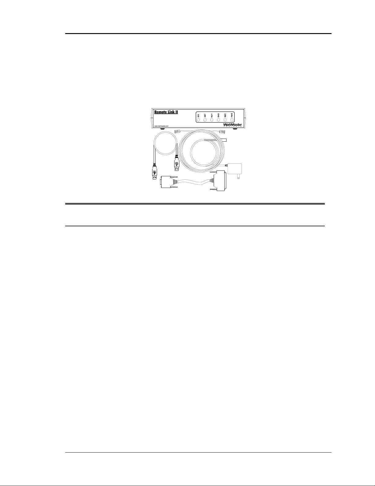
Optional Remote Link II
The Remote Link II is a 14,400 baud modem that can be used with a CommLink IV or a
computer. It is used to provide remote dial-up communications with the CommLink IV.
When it is used as a computer modem (at the remote computer location), it connects to
the remote computer.
Note: WattMaster will not support any other internal or external modems by other
manufacturers.
The OE419-06 Remote Link II connects to the CommLink IV communications interface
at the control system location via a DB9 serial cable. A telephone line connects the
Remote Link to the local phone service. Using another Remote Link modem connected to
a computer and phone service at a remote location, you can monitor and control the
system using the Prism computer front-end software. Connection is made by dialing the
telephone number of the job site where the Remote Link is located. See the Remote Link
II Technical Guide—WM-RLII-TGD for complete product details and installation
instructions.
Installation and Wiring 2-17
Page 30
Section 2 Auto-Zone CV & CV-EX
C
g
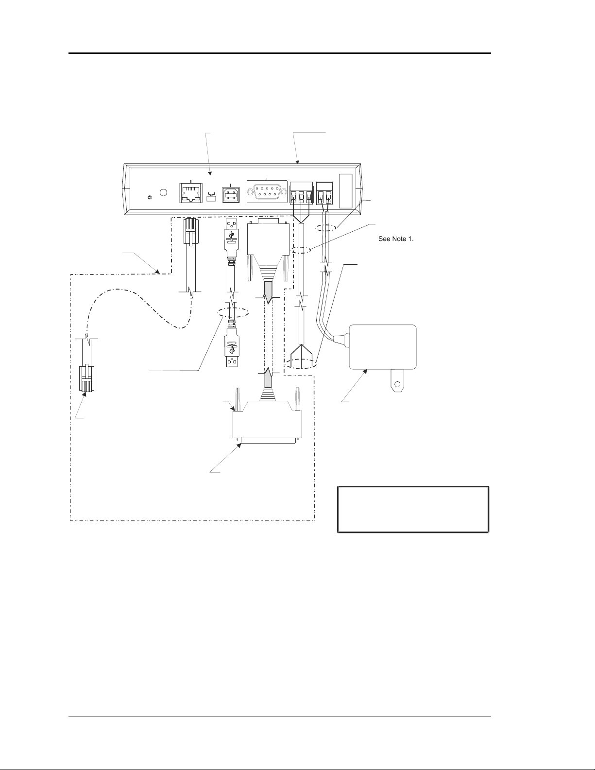
CommLink IV Wiring
USB Switch
Should Be Set
To N o r m al
MODEM
RS-232
Female
TGR
485 LOOP
9Pin
Optional Items Not
Required For
DIAG
10/100
ETHERNET
ACT LNK
USB
Normal
Config
COMPUTER
USB
CommLink Only
Installations
Optional - Prefabricated Ft. Long CAT5
Ethernet Cable (Included With Optional OE41502 IP Module Kit).
Ethernet Router On Your LAN.
Ethernet Cable Is Required, You Will Need To
Obtain (From Others) And Install An Ethernet
Cable Of The Required Length For Your
Installation.
Notes:
1) Use 18-Gauge Minimum, 2-Conductor Twisted Pair With Shield Cable Belden #82760 Or Equivalent
(Not Included) To Connect The CommLink IV To The MiniLink On Network Loop Or Controller Or System Manager On Local Loop.
2) For Direct Connection Via USB, Your Computer Must Have An Unused USB Port Available. Drivers
For Your USB Port Are Provided On A CD Supplied With The CommLink IV And Will Need To Be
Installed On Your Computer In Order For It To Function Correctly. Please Refer to the CommLink IV
Installation Technical Guide Form: WM-CLIV-TGD
3) The CommLink IV Cannot Communicate With The Control System Through Its Ethernet Port And
USB Port At The Same Time.
4) All Wirin
.
USB Cable (Included). Connect
This Cable To Your Computer USB
Port For Directly Connecting To
CommLink IV. Also Used For
Advanced Configuration of
CommLink IV.
Molded Modem Cable.
Part #HZ000098
Supplied With RemoteLink II
10
Connect To A 10/100 Base-T
Must Conform To Applicable Federal, State & Local Electrical Wiring Codes.
If A Longer
When An Optional Remote
Link Is Used, Connect This
Cable To CommLink IV And
Remote Link As Shown. Cable
Is Included With Remote Link.
Which Is Supplied With The CommLink IV.
25 Pin
Male
ommLink IV
Communications Interface
Serial #
GND
24V
POWER
WARNI NG!
24 VAC Power
18-Gauge, 2-Conductor
With Shield (Not Included)
Connect To The Controller Or System
Manager On Local Loop Or MiniLink
On Network Loop. See Note 1.
120 to 24 VAC Power Pack
(Included) Connect To 120/1/60 Duplex
Receptacle (By Others)
If Desired A 24 VAC Transformer
Included)
Rated At 12 VA Minimum May Be
Used Instead Of The Supplied Power Pack.
Use 18 Gauge Minimum 2 Conductor Wire
Between The Transformer & CommLink IV
Terminals.
If You Are Using The IP Module
With Your CommLink, Do Not Have Your
Ethernet Connection And USB Connection
Connected At The Same Time. This Could
Cause Unreliable Communications.
Figure 2-12: CommLink IV Interface Wiring
(Not
2-18 Installation and Wiring
Page 31

Auto-Zone CV & CV-EX Section 2
q
CommLink IV DIP Switch Setting
CommLink IV Communication Settings
The SW1 DIP Switch Located On The Circuit Board Inside
The CommLink IV Housing Must Be Set Correctly For
Your Specific Application In Order To Function Properly.
The CommLink IV Is Factory Set For Multiple Loop
Applications.
To Check And/Or Set The SW1 Dip Switch, First Remove
The (2) Enclosure Screws That Hold The Top And Bottom
Of The CommLink IV Enclosure Together. Remove The
Top Half Of The Enclosure To Access The Circuit Board
And Dip Switches.
SW1
The DIP Switch Setting Should Be Set To “Multiple”
For The Auto-Zone System
Replace The CommLink IV Cover And Secure The
Enclosure Halves Back Together With The (2) Enclosure
Screws That Were Previously Removed.
CV-EX .
WattMaster Controls Inc.
COMMLINK IV
YS102074
REV6
MADE IN USA
ALTERA
EPM3032
DIP Switch 1 & 2 Off =
Multiple Loop Communications
Re
uired Setting For Auto-Zone CV-EX System
Figure 2-13: CommLink IV DIP Switch Setting
Installation and Wiring 2-19
Page 32
Section 2 Auto-Zone CV & CV-EX
p
USB
MODEM
RS-232
TGR
485 LOOP POWER
T
DIAG
Comm Loop
10/100
ETHERNET
ACT LNK
Local
Config
USB
COMPUTER
Normal
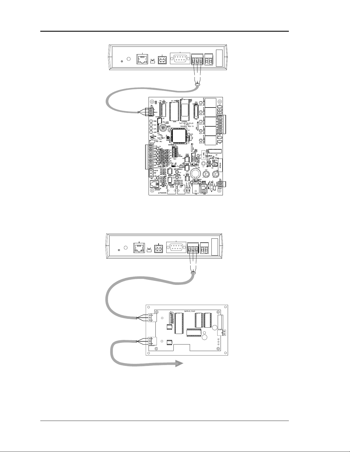
Figure 2-14: CommLink IV Wiring for CV System
Serial #
GND
24V
R
SHIELD
DIAG
Comm Loop
10/100
ETHERNET
ACT LNK
Network
Local
Comm Loo
Config
USB
USB
MODEM
RS-232
COMPUTER
Normal
MiniLink Communications Interface
ADD
1
2
NETWORK
T
4
8
SH
16
32
R
OFF >
LOOP
T
SH
R
TGR
485 LOOP
T
Local Communications Loo p
To CV Controllers
And System Manager
Serial #
GND
24V
POWER
R
SHIELD
24VAC
GND
Figure 2-15: CommLink IV to MiniLink Wiring for CV-EX System
2-20 Installation and Wiring
Page 33
Auto-Zone CV & CV-EX Section 2
Installing the CommLink IV
When you are using the CommLink IV with the Auto-Zone CV or CV-EX System and
are not going to use a Computer, Remote Link II, or IP Module, you only need to perform
three steps to install your CommLink IV.
Step #1:
Multiple if using the CV-EX system. See Figure 2-13 for details on setting the DIP
Switch on the CommLink IV.
Step #2:
with shield) from the CommLink IV to a CV Controller (CV system) or MiniLink (CVEX system).
For the CV system, the communication wiring should connect from the T, G, & R
terminals on the CommLink IV to the T, SHLD, & R terminals on the CV Controller. See
Figure 2-14. Be sure that you wire the CommLink “T” terminal to the CV Controller
“T” terminal, The CommLink “G” Terminal to the CV Controller “SHLD” terminal, and
the CommLink “R” terminal to the CV Controller “R” terminal as shown.
For the CV-EX system, the communication wiring should connect from the T, G, & R
terminals on the CommLink IV to the network T, SH, & R terminals on the MiniLink.
See Figure 2-15. Be sure that you wire the CommLink “T” terminal to the MiniLink “T”
terminal, The CommLink “G” Terminal to the MiniLink “SH” terminal, and the
CommLink “R” terminal to the MiniLink “R” terminal as shown.
Step #3:
terminals on the CommLink IV. Plug the power pack into a standard 120 VAC duplex
outlet.
If you intend to use a Computer, Remote Link II, or IP Module in addition to the steps
just performed, you will need to perform additional installation procedures. Please refer
to the CommLink IV Technical Guide—WM-CLIV-TGD which is supplied with the
CommLink IV. It will instruct you regarding installation and troubleshooting of the
CommLink when an optional personal computer and/or other communication devices are
used. This manual is also available from any of the WattMaster websites for downloading
as are the USB drivers and Prism Software. These are required for installation when using
the optional personal computer or other communication devices.
Check and make sure your CommLink’s communication switch is set to
Install communications wiring (18-gauge minimum, 2-conductor twisted pair
Wire the supplied 120/24 VAC power pack to the 24 VAC and GND
Installation and Wiring 2-21
Page 34
Section 2 Auto-Zone CV & CV-EX
System Manager
The microprocessor-based System Manager is a device which allows the CV Controller
or any add-on device connected to the system to be programmed and monitored from a
central location. The System Manager is connected via the RS-485 communication
network.
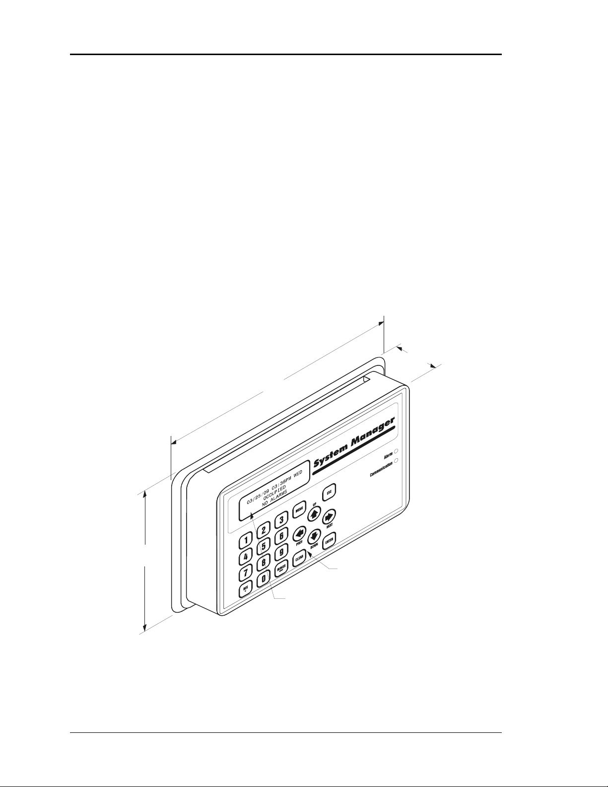
The System Manager is mounted in an attractive, white, plastic housing, suitable for wall
mounting. A four-line-by-twenty-character, backlighted, LCD display and membrane
keypad provide a user-friendly interface. All system variables, setpoints, and values can
be viewed and modified from the System Manager. Menu-driven programming makes the
System Manager easy to set up your system and operate it without the need for
specialized training.
6.25
1.90
9.00
Membrane
Keypad
Four Line by 20 Character
Backlighted Display
Figure 2-16: System Manager Dimensional Data
2-22 Installation and Wiring
Page 35
Auto-Zone CV & CV-EX Section 2
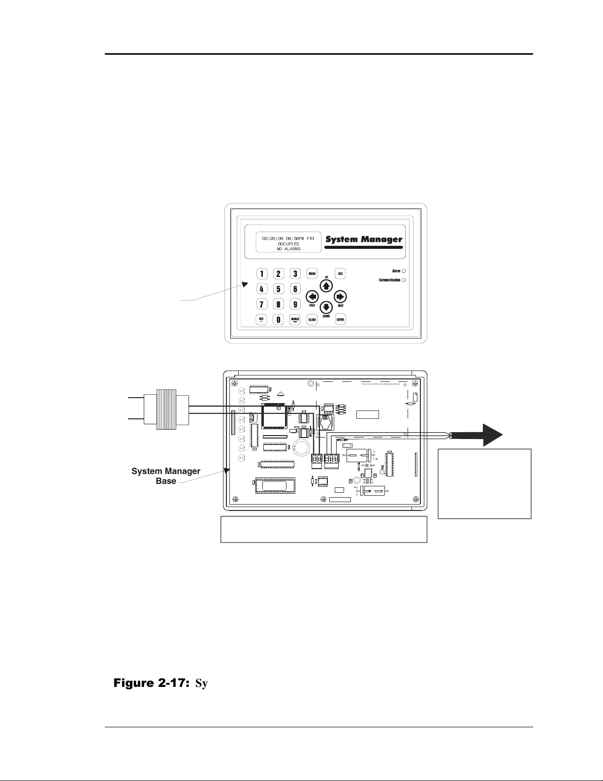
System Manager Wiring
The System Manager can be connected anywhere on the CV or CV-EX system local
communications loop. Do Not Connect the System Manager to the CV-EX System
Network Loop! The system will not function if the System Manager is connected to the
network loop. The System Manager must also be connected to 24 VAC in order to
operate. See Figure 2-17 for System Manager wiring.
03/20/09 06:38PM FRI
OCCUPIED
NO ALARMS
System Manager
Top
Required VA For Transformer
System Manager = 25VA Max.
Line Voltage
See Note 1
System Manager
Base
LD1
GND
24VAC
LD2
LD3
LD4
LD5
LD6
RN1
LD7
LD8
The Ideal Recommended Location For The System Manager Is As The First
Device On The Local Loop. The System Manager May Be Connected To The
Local Loop At Any Point On The Local Loop.
YS101806 REV. 1
74HC259
U2
R1
R2
U3
PCB80C552-5-16WP
DfD9722V7Y
442860=2/5
PHILIPS
PHILIPS
X1
C2C1
RN2
74HC573
U7
CX13
74HC573
CX7
U8
CX9
V62C518256L-70P
U9
SS0017
vx.xx 1234
U13
UNIVERSAL SMART DISP. UNIT
DSPY1
EWDOG
CX4
X2
CX8
U3
R3
CX5
24C128
U5
D3
R7
CX6
C3
8583
U6
24VAC
SC1
RAM
TB1
CX12
EPROM
R10
RS-485
COMM
CX3
GND
U12
75176
D1
R5
82B715
R6
D2
PJ1
R12
D4
SHLD
T
VAR1
R
C4
TB2
L1
C11
MADE IN
THE USA
SERIAL #
CX1
SYSTEM MANAGER
U1
Notes:
1.) 24 VAC Must Be Connected So
That All Ground Wires Remain
Common.
2.) All Wiring To Be In Accordance
With Local And National Electrical
Codes And Specifications.
3.) All Communication Wiring To Be
2-Conductor Twisted Pair With
Shield. Use Belden #82760 Or
Equivalent.
470uF50v
D6
DSPY1
SERIAL # :
C7
1000uF10v
C9
RV1
R4
See Note 3
U10
74HC923
R8
C5
MC34064A
U11
9936
C8
C6
R9
R11
1000uF10v
For CV Systems, Connect To Any
CV Controller On The Local Loop
Or To The CommLink. For The
CV-EX System, Connect To Any
Controller On The Local Loop Or
To The Local Loop Terminal On
The MiniLink.
Do Not Connect To The
Network Loop On CV-EX
Systems!
P1
CX10
470uF50v
Figure 2-17: System Manager Wiring
Installation and Wiring 2-23
Page 36

Section 2 Auto-Zone CV & CV-EX
p
MiniLink Interface
The MiniLink Interface is only required and used with the CV-EX system. It is not
required for the CV system. It functions as the loop master for each CV-EX system local
loop. With the CV-EX system, each local loop of CV controllers (maximum of 30) is
connected to a MiniLink. Two MiniLinks are supplied with the standard CV-EX system.
This allows up to 60 CV controllers (30 maximum per local loop) to be tied together to
form an integrated system. A CV-EX expansion kit is available which provides another
MiniLink to allow an additional 30 CV controllers to be connected to the system. A
maximum of two expansion kits can be used on the CV-EX system to provide integration
of up to 120 CV controllers. See Figure 2-18 for an overview of the MiniLink.
Network Loop
Communications
Driver Chip
Network Loop
Communications
LED
( Each Board Must Be Addressed Uniquely )
Address Switch
Switch Shown Set For Address 1
( 1,2,3,4)
ADD
Network Loop
Connector
Local Loop
Communications
LED
Local Loop
Connector
NETWORK
T
SH
R
4.50"
T
SH
R
1
2
4
8
16
32
OFF >
LOOP
Local Loop
Communications
Driver Chi
Figure 2-18: MiniLink Interface Overview
24 VAC
Power
24VAC
GND
7.50”
2-24 Installation and Wiring
Page 37

Auto-Zone CV & CV-EX Section 2
MiniLink Interface Wiring
All MiniLinks on the CV-EX system must be wired to each other with a Network
communications loop, daisy-chaining the Network loop terminals together. One end of
the CV-EX system Network loop must be connected to the CommLink IV interface. Each
MiniLink on the CV-EX system is then wired from its Local loop terminals to the CV
Controllers on that Local loop. The MiniLink also requires 24 VAC power to operate.
Each MiniLink must be addressed from 1 to 4 with a unique address. The addresses are
set with the address switch at each MiniLink board. See Figure 2-18 for the address
switch location. See Figure 2-19 for wiring information.
Connect To Next
MiniLink And/Or
CommLink On
Network Loop
Network Loop
RS-485
19200 Baud
(See Note 3).
All Communication Loop
Wiring Is Straight Through
T
T
SH
R
Local Loop
RS-485
9600 Baud
(See Note 3).
T
SH
SH
R
R
T
SH
R
MiniLink Communications Interface
ADD
1
2
NETWORK
T
4
SH
8
16
32
R
T
SH
R
OFF >
LOOP
24VAC
GND
24VAC
GND
Required VA For Transformer
MiniLink = 10VA Max.
See Note 1.
Line Voltage
Connect To CV
Controller or
System Manager
On Local Loop
Notes:
1.)24 VAC Must Be Connected So
That All Ground Wires Remain
Common.
2.)All Wiring To Be In Accordance
With Local And National Electrical
Codes And Specifications.
Figure 2-19: MiniLink Interface Wiring
3.) All Communication Wiring To Be
2 Conductor Twisted Pair With
Shield. Use Belden #82760 Or
Equivalent.
Installation and Wiring 2-25
Page 38

Section 2 Auto-Zone CV & CV-EX
CV & CV-EX Worksheet
Project: ___________________________ Location ___________________________
Stages of Cool: ___ Stages of Heat: ___ Gas Electric Economizer Yes No
Loop: 1 2 3 4 Remote Link Installed Yes No Phone No. ___________
Unit
Unit Description or Location Sensor Type
Address
1
2
3
4
5
6
7
8
9
10
11
12
13
14
15
16
17
18
19
20
21
22
23
24
25
26
27
28
29
30
[S=Sensor] [SO=Sensor w/ Override] [SA=Sensor w/ Setpoint adjust] [SOA=Sensor w/ Override & Setpoint Adj.
S SO SA SOA
S SO SA SOA
S SO SA SOA
S SO SA SOA
S SO SA SOA
S SO SA SOA
S SO SA SOA
S SO SA SOA
S SO SA SOA
S SO SA SOA
S SO SA SOA
S SO SA SOA
S SO SA SOA
S SO SA SOA
S SO SA SOA
S SO SA SOA
S SO SA SOA
S SO SA SOA
S SO SA SOA
S SO SA SOA
S SO SA SOA
S SO SA SOA
S SO SA SOA
S SO SA SOA
S SO SA SOA
S SO SA SOA
S SO SA SOA
S SO SA SOA
S SO SA SOA
S SO SA SOA
2-26 Installation and Wiring
Page 39

Auto-Zone CV & CV-EX Section 2
Index
< 30 Controllers .................................. 24
> 30 Controllers .................................. 24
120 CV controllers.............................. 24
14,400 Baud Modem........................... 17
24VAC-to-24VAC.............................. 10
90% RH................................................. 8
Above 140° F ........................................ 8
Addresses
CV Worksheet................................... 1
CV-EX Worksheet ............................ 1
List .................................................. 26
Address Switch Setting
CV Controller.................................. 11
Addressing
Controllers......................................... 1
CV Controller.................................. 11
MiniLinks........................................ 24
AIN1.................................................... 13
AIN2.................................................... 13
AUX.................................................... 13
Belden No. 82760 ................................. 4
Below 20° F .......................................... 8
Cable
Belden 82760 .................................... 4
DB9................................................. 17
Serial ............................................... 17
Telephone Line ............................... 17
Two Wire Shielded ........................... 4
Codes, Standard
Wiring ............................................... 1
CommLink IV
Connecting to MiniLink.................. 20
Dip Switch Setting .......................... 19
Installing.......................................... 21
Jumper Setting ................................ 19
Overview......................................... 16
Technical Guide .............................. 21
Wiring ............................................. 18
Communication Loop
Wiring Diagram, CV EX System...... 6
Communication Loop Wiring
CV System ........................................ 5
Communications Loops
CV System ........................................ 4
CV System Wiring Diagram............. 5
CV-EX System.................................. 4
Local Loop ........................................ 4
Network Loop ................................... 4
Overview........................................... 4
Wiring Overview .............................. 5
Conduit.................................................. 7
Configuration
Daisy Chain....................................... 4
Star .................................................... 7
Controllers
< 30 ................................................. 24
> 30 ................................................. 24
Addressing ........................................ 1
Damage ........................................... 10
List .................................................. 26
CV Address Worksheet......................... 1
CV Controller
Address Switch Setting................... 11
Addressing ...................................... 11
Backplate Components ..................... 8
Electrical Connections .................... 10
Installing............................................ 8
Mounting........................................... 8
Wiring ............................................... 9
Wiring Diagram ................................ 9
CV System
Communications Loops .................... 4
Diagram............................................. 2
Overview........................................... 2
Sensors ............................................ 12
Wiring Diagram ................................ 5
CV Worksheet..................................... 26
CV-EX Address Worksheet.................. 1
Installation and Wiring 2-27
Page 40

Section 2 Auto-Zone CV & CV-EX
CV-EX System
Communication Loop Wiring........... 6
Communications Loops .................... 4
Diagram............................................. 3
Expansion Kit ................................. 24
Overview........................................... 3
Worksheet ....................................... 26
Daisy Chain..................................... 4, 25
Configuration .................................... 4
Daisy-Chain Configuration
CV-EX System Wiring Diagram ...... 6
Diagram............................................. 5
Damage
Controller ........................................ 10
Damp Environments ............................. 8
DB9 Serial Cable ................................ 17
Diagram
CV System ........................................ 2
CV-EX System.................................. 3
Dial-up Communications.................... 17
Dial-up Connections ........................... 16
Dimensions
System Manager.............................. 22
DIP Switch............................................ 4
Electrical
Short.................................................. 4
Electrical Connections
CV Controller.................................. 10
Enclosure
Weathertight...................................... 8
Environmental Limitations
Installation......................................... 8
Environments
Damp................................................. 8
Wet.................................................... 8
Expansion Kit ..................................... 24
Extreme High Temperatures ................. 8
Extreme Low Temperatures.................. 8
Firewall ............................................... 16
Fluorescent Lights................................. 7
Furnace Ignition System Wires............. 7
GND-to-GND ..................................... 10
Humidity
90% RH............................................. 8
Installation
CommLink IV................................. 21
CV Controller.................................... 8
CV System ........................................ 1
CV-EX System.................................. 1
Environmental Limitations ............... 8
Outside Air Sensor.......................... 15
Room Sensors ................................. 12
Supply Air Temperature Sensor...... 14
System Manager.............................. 22
Tips ................................................... 1
Intranet Connection............................. 16
IP Module
Overview......................................... 16
IP-Module Technical Guide................ 16
Jumper Setting
CommLink IV................................. 18
LAN and Internet Connections ........... 16
LCD Display
System Manager.............................. 22
Local Codes........................................... 7
Local Loop ............................................ 4
Marble Walls....................................... 12
Metal Shavings.................................... 10
MiniLink ............................................... 4
Address Location ............................ 24
Overview......................................... 24
Wiring ............................................. 25
Modem
Internal ............................................ 17
Other Manufacturers’...................... 17
Remote Link II................................ 17
Mounting
Room Sensors ................................. 12
Mounting Backplate.............................. 8
Multiple Setting .................................. 21
Network Loop ....................................... 4
OE415-02 IP Module Kit.................... 16
OE419-06 Remote Link II .................. 17
Outside Air Sensor
Inaccurate Readings ........................ 15
Installing.......................................... 15
Outside Air Temperature Sensor......... 15
2-28 Installation and Wiring
Page 41

Auto-Zone CV & CV-EX Section 2
Overview
CommLink IV................................. 16
Communications Loops .................... 4
CV System ........................................ 2
CV-EX System.................................. 3
IP Module........................................ 16
MiniLink ......................................... 24
Remote Link II................................ 17
System Manager.............................. 22
Systems ............................................. 2
Plastic Bezel........................................ 13
Polarity............................................ 1, 10
Prism ....................................... 16, 17, 21
Radio Transmitting Equipment............. 7
Remote Link II.................................... 16
Described ........................................ 17
Overview......................................... 17
Requirements
Electrical, CV Controller ................ 10
Rooftop Unit Discharge ...................... 14
Room Sensors ..................................... 12
Installing.......................................... 12
Mounting......................................... 12
Wiring ............................................. 13
Router.................................................. 16
RS-485 ............................................ 4, 22
Sensors
CV System ...................................... 12
Outside Air Temperature ................ 15
Room............................................... 12
Supply Air Temperature.................. 14
Short
Electrical ........................................... 4
Splice..................................................... 4
Star Configuration
Wiring ............................................... 7
Steel Walls .......................................... 12
Supply Air Temperature Sensor
Installing.......................................... 14
Location .......................................... 14
System Manager
Dimensions ..................................... 22
Installling ........................................ 22
Overview......................................... 22
Wiring ............................................. 23
Systems
Overview........................................... 2
TB3 ..................................................... 13
TCP/IP Internet ................................... 16
Telephone Line ................................... 17
Temperatures
Above 140° F .................................... 8
Below 20° F ...................................... 8
Extreme High .................................... 8
Extreme Low..................................... 8
Humid ............................................... 8
Terminals
AIN1................................................ 13
AIN2................................................ 13
TB3 ................................................. 13
TMP ................................................ 13
TMP .................................................... 13
Transformers ......................................... 7
TV Transmitting Equipment................. 7
Two Wire Shielded ............................... 4
USB Drivers........................................ 21
Variable Frequency Drives ................... 7
Voiding, Warranty ................................ 1
Warranty, Voiding ................................ 1
Weathertight Enclosure......................... 8
Wet Environments ................................ 8
Wiring ................................................... 1
24VAC-to-24VAC.......................... 10
Color ................................................. 4
CommLink IV................................. 18
Communication Loops...................... 5
Conduit.............................................. 7
Continuous ........................................ 4
CV Communication Loop................. 5
CV Controller.................................... 9
CV Controller, Diagram.................... 9
CV-EX System.................................. 6
Diagram, CV System ........................ 5
GND-to-GND ................................. 10
Incorrect ............................................ 4
Local Codes....................................... 7
Mapping ............................................ 1
MiniLink ......................................... 25
Path ................................................... 7
Polarity........................................ 1, 10
Installation and Wiring 2-29
Page 42

Section 2 Auto-Zone CV & CV-EX
Room Sensor................................... 13
Shortest Path ..................................... 7
Splice................................................. 4
Star Configuration............................. 7
System Manager.............................. 23
System Manager
LCD Display ................................... 22
2-30 Installation and Wiring
Page 43

Section 3
Table of Contents
LCD/Keypad Operations................................................... 1
Keypad Functions ............................................................................................................1
System Manager LED Indicators .....................................................................................2
Screen Menus ..................................................................2
View Alarms Screen ........................................................5
Full System Access .........................................................6
Set Time & Date ..............................................................6
New Passcodes................................................................ 8
Rebuild Alarm Map........................................................... 9
Read/Reset Units ........................................................... 10
CV Controller Force Modes ...........................................11
CV Controller Read/Reset Operations........................... 12
CV Controller Status...................................................... 13
CV Controller Setpoints................................................. 16
CV Controller Scheduling and Holidays ........................ 22
Week Schedules .............................................................................................................22
Holidays .........................................................................................................................23
Economizer Module (Wetbulb) Read/Reset Operations 24
System Manager Keypad Operations Summary............ 26
Index .............................................................................. 27
Programming
Page 44

Section 3 Auto-Zone CV & CV-EX
Programming
Page 45

Auto-Zone CV & CV-EX Section 3
LCD/Keypad Operations
Keypad Functions
The System Manager keypad is labeled either numerically or as to actual function for that
key. Below is a summary of the labeled keys and their functions.
03/20/09 06:38PM FRI
OCCUPIED
NO ALARMS
MENU This key is used to gain access to the first menu, and you will be
notified on the LCD if any subsequent use of the key will be required
for further access.
ESC The ESCape key allows you to abort what you are doing or exit back
to previous menus. Also, anytime you want to leave the system
unattended, you should press the ESC key until the Main Screen
appears.
CLEAR If you make a mistake while entering setpoint data, you can clear the
bad data from the display by pressing the Clear key.
ENTER Use the Enter key to close out a data entry. The Enter key can also be
used to advance to the next field or screen.
DEC If entering a setpoint that requires a decimal point, press this key
where the decimal is located while entering the value.
MINUS If you need to enter a negative value, you must press the Minus key
before entering the digits for that value.
UP/DOWN
Arrows
LEFT/RIGHT
Arrows
Use these keys to step forward or backward through Status Screens or
Setpoint Data Fields.
If the screen prompts you to use these keys, it is used normally to
toggle modes of operation. In some cases, they may be used for other
functions and you will be prompted as to what these might be.
Programming 3-1
Page 46

Section 3 Auto-Zone CV & CV-EX
System Manager LED Indicators
There are two LED indicators located on the right-hand side of the System Manager.
The top LED indicates an Alarm condition if the Manager detects an alarm condition
while polling the system.
The bottom LED is active during actual communications or packet transfers. This LED
will normally "flicker" and not remain on constantly.
Screen Menus
Main Screen
vX.XX
Friday Operations
03/20/09 09:46 AM
Outdoor Air 78.0°F
The Auto-Zone System Manager is your direct link to the status and setpoints of any
Auto-Zone component on your communications loop. With the System Manager, you can
view any temperature or output condition and change any setpoint to fine-tune the
operations of the total system. All keypad operations are simple and straight-forward,
utilizing non-cryptic plain English messages. The System Manager automatically detects
the type of unit that has been selected and displays the appropriate status and setpoint
screens. The attractive plastic case of the System Manager allows for placement in any
area of your building.
The remainder of this section will lead you through the system menus and keypad
operations.
All user functions are accessed by pressing the Menu button. Once the button is pressed,
the Main User Menu is displayed.
3-2 Programming
Page 47

Auto-Zone CV & CV-EX Section 3
Main User Menu
1) View/Change Zone
2) View Alarms
MENU) Full Access
ESC) Main Screen
1) View/Change
Zone
2) View Alarms
MENU) Full
Access
ESC) Main
Screen
For quick access to an individual zone,
select this menu item. Any Constant
Volume unit can be selected. You can
view the room temperature and change
the current cooling and heating
setpoints. You must be at least a Level
1 user to change the setpoints.
If the System Manager has been
configured for Alarm Polling, you can
select this item to get a list of unit
addresses that are currently in alarm. If
an alarm exists, the Alarm LED will
be active on the right side of the panel.
If you are a Level 2 user, the full
system Read/Reset capabilities are
available to you. These capabilites are
accessed via this Menu button.
When you have finished viewing the
system, you can exit this menu and
return to the Main Screen by pressing
the ESC button.
View/Change Zone
View/Change
[ Enter Unit ID# ]
Selected Unit: 101
Programming 3-3
If you have selected the View/Change Zone menu item, you
will be allowed to view any selected zone temperature and its
current cooling and heating setpoints. If you are at least a
Level 1 user, you can also change the cooling and heating
setpoints from this screen. The first screen that appears
prompts you for the Unit ID you wish to view. For the CV
system, the Unit ID is actually the address of the CV
controller you assigned to each board with the Address
Switch—a number between 1 and 30. For the CV-EX system,
it would also be the same CV controller address you assigned,
but it would be preceded by the network loop address, which
is the address number (between 1 and 4) you set for the
MiniLink whose loop the particular CV controller resides on.
For example, the CV controller address is 28 and it is on the
loop with the MiniLink addressed 2. The ID number you
would enter would be 228.
Page 48
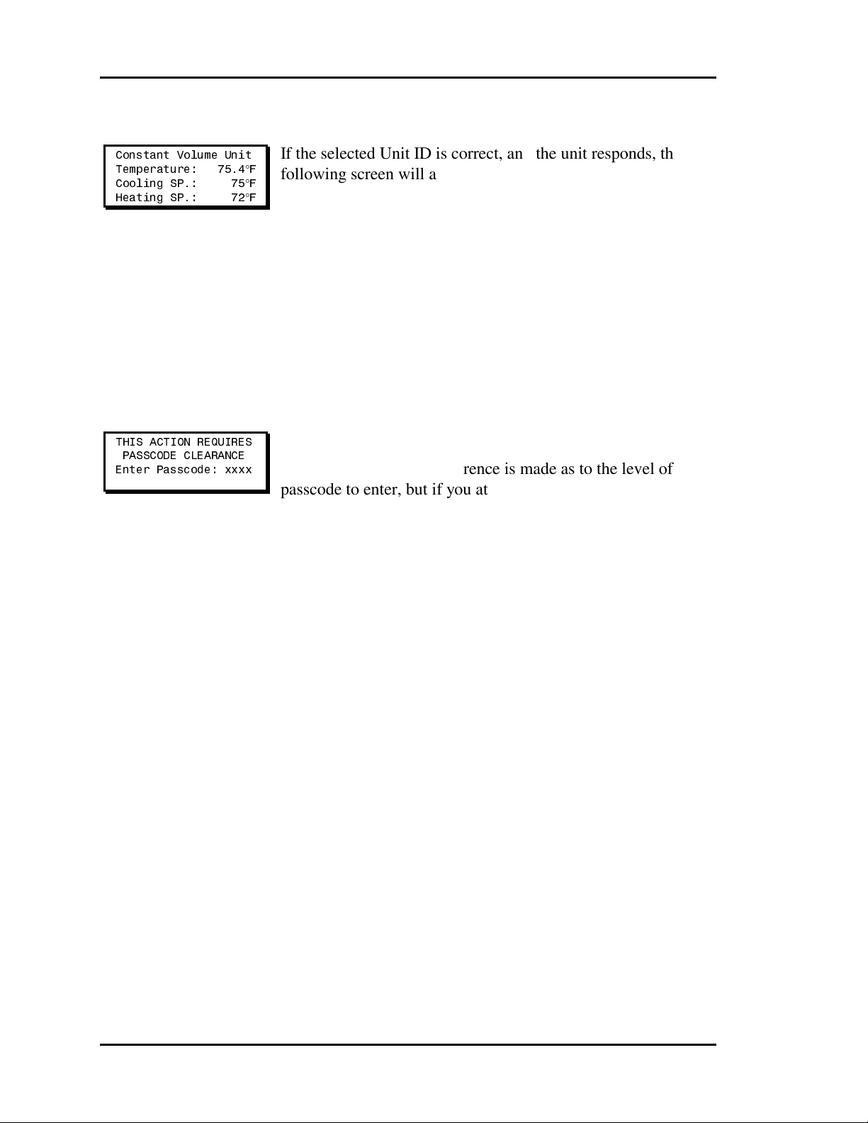
Section 3 Auto-Zone CV & CV-EX
Constant Volume Status
Constant Volume Unit
Temperature: 75.4°F
Cooling SP.: 75°F
Heating SP.: 72°F
If the selected Unit ID is correct, and the unit responds, the
following screen will appear. If you are a Level 1 user, you can
select either the Cooling or the Heating setpoint with the
Up/Down Arrow keys. To change the setpoint, use the
Left/Right Arrow keys. The setpoints are fully adjustable
between their normal limits of 50 to 90 degrees. When you are
finished viewing this screen, simply press the ESC button to
exit. The Heating Setpoint is never allowed to get any closer
than one degree of the Cooling setpoint. If you are lowering the
Cooling setpoint or raising the Heating setpoint, both values
will be kept apart automatically by the correct amount.
Entering Passcodes
THIS ACTION REQUIRES
PASSCODE CLEARANCE
Enter Passcode: xxxx
Anytime you are prompted to enter a passcode, the following
screen will appear. No reference is made as to the level of
passcode to enter, but if you attempt to access a Level 2
function with a Level 1 passcode, the system will prompt you
to enter the correct passcode again.
3-4 Programming
Page 49

Auto-Zone CV & CV-EX Section 3
View Alarms Screen
Alarm Address Locations
SYSTEM ALARM STATUS
Alarm @ Unit ID 118
Alarm Clearing
SYSTEM ALARM STATUS
Clear Alarms? YES
To Change Response
Use Left/Right Arrow
The System Manager can be programmed to poll all Auto-Zone
units on your system for alarm information. This allows the
centrally located System Manager to display an Alarm Indicator
whenever an alarm condition exists anywhere on your system.
The actual alarms are not displayed on this screen; only the
Unit ID where the alarm is located is displayed. The example
shows that a unit at location 118 has experienced an alarm
condition. This alarm may or may not be current, as the System
Manager latches the alarm condition. This makes it possible to
determine if any intermittent alarm conditions have occured. If
you have Level 2 access, you can enter the full system access
mode, select that unit for display, and determine the exact
alarm condition for that unit. The alarm conditions are always
displayed on the Status Screens.
If all the alarm conditions have been corrected at the individual
units, you can clear these alarms from the System Manager on
the following screen. Use the Left/Right arrow keys to select
the YES/NO response desired. If you clear the alarms, but
some still exist, the System Manager will show an alarm
indication when the affected unit is polled again.
Programming 3-5
Page 50
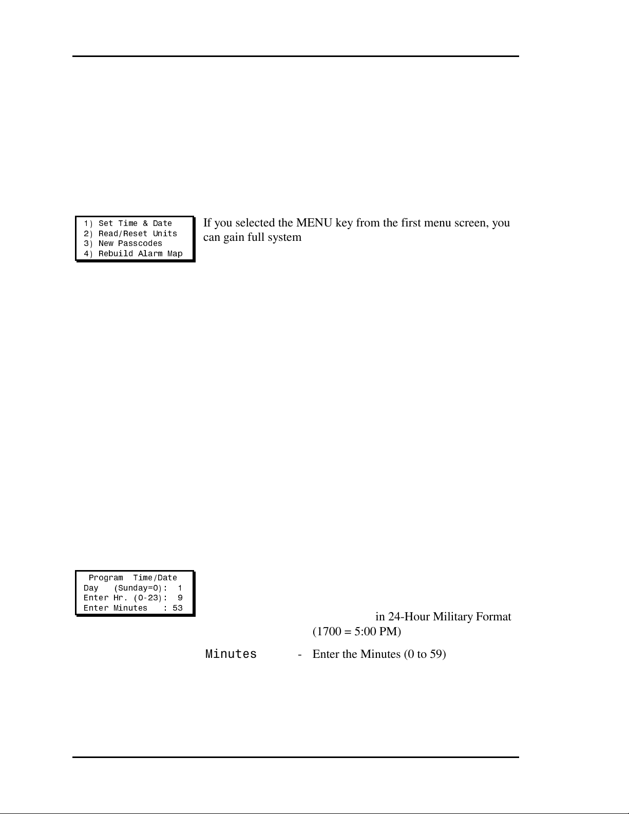
Section 3 Auto-Zone CV & CV-EX
Full System Access
Full Access Menu
1) Set Time & Date
2) Read/Reset Units
3) New Passcodes
4) Rebuild Alarm Map
If you selected the MENU key from the first menu screen, you
can gain full system access. However, you must be a Level 2
user. If you haven't already been asked to enter the passcode,
you will be asked before the Full Access Menu is displayed.
This prevents a Level 1 user from being overwhelmed with the
full amount of data and setpoints available to the Level 2 user.
Set Time & Date
The System Manager has its own built-in Real Time Clock. It broadcasts this time once a
day at midnight to synchronize all of the other units on your Auto-Zone system. Although
the times are displayed on the Main Screen in a standard 12-hour format, they are
programmed using the 24-hour Military format. Once the time has been entered, it is also
broadcast immediately to all other units on the system. That means that you only need to
program the System Manager time to set the Real Time Clocks for all units on your
communications loop.
Programming Time
Program Time/Date
Day (Sunday=0): 1
Enter Hr. (0-23): 9
Enter Minutes : 53
Day
Hours (Hr)
Minutes
- Enter the Day of the Week (0 to 6) with
Sunday = 0
- Enter Hours in 24-Hour Military Format
(1700 = 5:00 PM)
Enter the Minutes (0 to 59)
-
3-6 Programming
Page 51

Auto-Zone CV & CV-EX Section 3
Programming Date
Program Time/Date
Month (1-12): 3
Day (1-31): 20
Year (00-99): 09
Month
Day
Year
Daylight
Savings Adjustments
Daylight Savings
Adjustments Enabled
Use Left/Right Arrow
If your area of the country requires Daylight Savings changes,
you can enable the System Manager to automatically reset its
own clock during the Daylight Savings changeover. However,
if you enable this operation, be aware it will changeover the
first Sunday in April and then switch back the last Sunday in
October. These used to be the standard dates every year that
were constant from year to year.
The U.S. government has seen fit recently to arbitrarily
determine the switch over dates each year so it is
recommended that you disable this function and manually
change the schedules from year to year.
- Enter the Month (1 to 12)
Enter the Day of the Month
(1 to 31)
-
Enter the current Year with 2 digits
(00 to 99)
Use the Left or Right arrow keys to toggle the second line of
the display between Adjustments Enabled and Adjustments
Disabled.
Programming 3-7
Page 52

Section 3 Auto-Zone CV & CV-EX
New Passcodes
Programming Passcodes
Enter New Passcode
Level 1.....: XXXX
Level 2.....: XXXX
[Must Be 4 Digits]
Caution: If you change the Level 2 passcode and cannot remember what it is, you
will be locked out of your system!
The System Manager has two levels of user access.
Level 1 users are limited to viewing or changing Zone
Temperatures and their Heating and Cooling Setpoints and to
viewing Unit ID numbers for those in alarm conditions.
Level 2 users have complete system access. Any status or
setpoint field can be read or reset from the Auto-Zone system.
These two levels of passcodes are programmable by any Level
2 user. The default Level 1 passcode is 1111, and the default
Level 2 passcode is 2222.
The actual digits in your passcodes are never displayed. An "X"
is used as a place holder for each digit entered. Passcodes must
always be four digits in length, so the useable range of numbers
is 1000 to 9999.
3-8 Programming
Page 53

Auto-Zone CV & CV-EX Section 3
Rebuild Alarm Map
Rebuilding Screens
Clearing Old Map
....................
................
Building New Map
Loop: 1
Unit: 1
FOUND
Alarm Unit Map Built
Press Any Key To
Continue
If you would like the LED Alarm Indicator to function on the
front of your System Manager, you must enable Alarm Polling
by building an Alarm Map. This map keeps track of which
units exist on your communications loop so that the System
Manager will poll only those units. That means you will need
to rebuild this map anytime units are added or removed from
your system. It also means you can disable alarm polling. To do
this, disconnect the RS-485 communications plug from the
back of your CommLink IV. Then select the Rebuild Alarm
Map menu. The System Manager will not find any units to poll
for alarms since none are connected. This is useful during
building startup, when you don't want nuisance alarms
bothering you.
The screen will display each address it is testing if a unit is
FOUND at that address. If you have a CV system, you don't
have to wait for the System Manager to check for all 30 loops;
rather, you can press the ESC key as soon as the first loop has
been checked since the CV system only has one loop. All units
found up to that point will be saved in memory. The CV system
volume configuration only contains one loop, but the System
Manager will always attempt to determine if more than one
loop really exists. The CV-EX system will have 2 to 4 loops.
Be sure to allow time for the System Manager to find all the
local loops.
The System Manager does not rebuild this map automatically
on powerup! You must do this manually. This rebuild should
only be performed one time, when all units are up and running.
It is not a regular requirement. As mentioned above, only when
the number of units connected changes should the alarm map
be rebuilt.
Programming 3-9
Page 54

Section 3 Auto-Zone CV & CV-EX
Read/Reset Units
Read/Reset Address Entry
Read/Reset
[ Enter Unit ID# ]
Selected Unit: 101
You must know the Unit ID of the controller you wish to view.
This number is created by combining the network loop address
with the CV Controller board address on CV-EX systems. On
CV systems, the Unit ID is simply the CV controller board
address. The CV Controllers should always be addressed
starting with number 1 and continuing up to 30. The CV-EX
MiniLinks (network loop address) should be numbered starting
with 1 and continuing up to 4 (assuming you have 4 loops).
Don’t skip numbers.
Once you have finished the Read/Reset function, you can exit
this mode by pressing the ESC key. This will return you to the
Full Access Menu.
3-10 Programming
Page 55
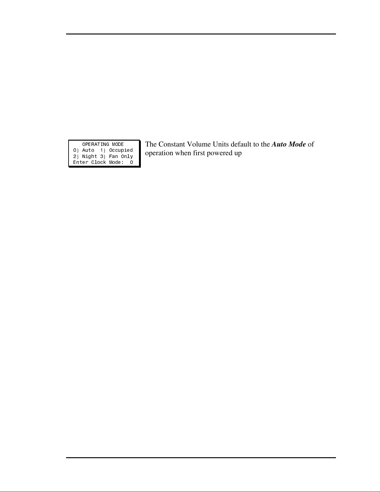
Auto-Zone CV & CV-EX Section 3
CV Controller Force
Modes
OPERATING MODE
0) Auto 1) Occupied
2) Night 3) Fan Only
Enter Clock Mode: 0
The Constant Volume Units default to the Auto Mode of
operation when first powered up. Any force modes entered will
be retained in non-volatile memory. The unit will resume the
force mode of operation anytime the power is cycled.
0) Auto
1) Occupied
2) Night
3) Fan Only
- Use internal schedules for Day/Night
Mode
- Forced to Continuous Day or Occupied
Mode
- Forced to Continuous Night or
Unoccupied Mode.
- This mode disables any heating or cooling
and operates the Fan only. You can use
this mode anytime you want to manually
purge your building.
Programming 3-11
Page 56

Section 3 Auto-Zone CV & CV-EX
CV Controller
Read/Reset Operations
If the Unit ID you entered found a Constant Volume AHU, the following menus will
appear. Any references in this section to CVAHU are referring to the Constant Volume
Air Handling Unit or its controller.
CV Controller Menu #1
1) CVAHU Status
2) CVAHU Setpoints
MENU) Next Menu
ESC) To Exit
1) CVAHU Status
2) CVAHU Setpoints
MENU) Next Menu
CV Controller Menu #2
1) Schedules
2) Force Modes
MENU) Previous Menu
1) Schedules
2) Force Modes
MENU) Previous
Menu
View the current temperatures
and operating modes for this
Constant Volume AHU.
View or change any of the
available setpoints for this
Constant Volume AHU.
Access the next Menu Page for
the Constant Volume AHU.
View or change any of the Week
Schedules or Holidays for this
Constant Volume AHU.
Select this menu to override the
currently scheduled operating
mode.
Return to the previous menu
shown above.
3-12 Programming
Page 57

Auto-Zone CV & CV-EX Section 3
CV Controller Status
Line 1 displays the currently selected CVAHU and its current operating software version
on all Status Screens shown below.
Status Screen #1
CVAHU # 18 vl.xx
Occupied Mode
Neutral Mode
Line 2 -
Line 3 -
Line 4 - (Reserved for Future Use)
Status Screen #2
CVAHU # 18 vl.xx
Temperature: 78.6ºF
CSP 75.0 HSP 72.0º
Slide Adjust.: 0.0°
Line 2 - Displays the current Zone Temperature.
Line 3 - Displays the currently active Cooling
Line 4 - Displays the current effect the optional
Unoccupied Mode
Occupied Mode
Holiday Active
Push-button Override
Forced Occupied
Forced Unoccupied
Forced Fan Only Mode
Neutral Mode
Cooling Mode
Heating Mode
This Line is Blank
Setpoint (CSP) and Heating Setpoint
(HSP).
Sensor Slide Adjust has on the Heating and
Cooling Setpoints.
Programming 3-13
Page 58

Section 3 Auto-Zone CV & CV-EX
Status Screen #3
CVAHU # 18 vl.xx
Supply Air.: 65.0°
Outdoor Air.: 70.2°
Wetbulb Temp: 0.0°
Line 2 - Displays the current Supply Air Temperature.
Line 3 - Displays the current Outdoor Air Temperature.
Line 4 - Displays the current Wetbulb Temperature if
Status Screen #4
CVAHU # 18 vl.xx
Economizer...: 10%
Heating Locked Out
Fan On
Line 2 - Shows the current Economizer Damper position if
Line 3 -
Line 4 -
Status Screen #5
available.
the CVAHU has been configured to control the
Economizer.
(This line is blank if the CVAHU does not control
the Economizer.)
No Lockouts Active
Cooling Locked Out
Heating Locked Out
Fan Off
Fan On
Heating Stage #1 OFF
Heating Stage #2 OFF
Cooling Stage #1 OFF
Cooling Stage #2 OFF
This screen shows how the relays were configured, either for
Heating or Cooling. The first line shows the status of Relay #2,
the second line shows the status of Relay #3, etc.
The message will show ON/OFF status for that relay.
3-14 Programming
Page 59

Auto-Zone CV & CV-EX Section 3
Status Screen #6
CVAHU # 18 vl.xx
Zone Cooling ALARM
Line 2 -
Line 3 -
Zone Sensor O.K.
Bad Zone Sensor!
Zone Cooling ALARM
Zone Heating ALARM
The line will show Zone Sensor OK if none of the
above alarm conditions exist.
Binary Input ALARM
This line will remain blank if the contact has not
closed. This input is normally used for Dirty Filter
Alarms.
If no alarm conditions exist, then line 3 will display
the words No Alarms!
Note: If no alarm conditions exist, then line 3 will display the words No Alarms!
Line 4 -
Mech Cooling ALARM
Mech Heating ALARM
This line remains blank if no alarm condition
exists.
These alarms are generated when the Supply
Temperature does not change more than five
degrees after a stage of heating or cooling has been
activated for 30 minutes.
Programming 3-15
Page 60

Section 3 Auto-Zone CV & CV-EX
CV Controller Setpoints
Line 1 displays CVAHU Setpoints message for identification only.
Setpoint Screen #1
CVAHU Setpoints
Occupied Setpoints
Cooling Setpt: 75°F
Heating Setpt: 72°F
The Occupied Heating and Cooling Setpoints are entered on
this screen. The Heating Setpoint should always be at least one
degree below the Cooling Setpoint, or the CVAHU will not
accept the new values.
Cooling Setpoint 50°F 75°F 90°F
Heating Setpoint 50°F 72°F 90°F
Setpoint Screen #2
CVAHU Setpoints
Unoccupied Setpoints
Cool Setup...: 10°F
Heat Setback.: -10°F
The Unoccupied Heating and Cooling Setup values are
entered on this screen. The Occupied Cooling Setpoint will be
increased by the Cooling Setup during Unoccupied Mode, and
the Heating Setpoint will be decreased by the Heating Setback.
Cooling Setup 0°F 10°F 30°F
Heating Setback 0°F -10°F -30°F
Minimum
Minimum
Default
Default
Maximum
Maximum
3-16 Programming
Page 61

Auto-Zone CV & CV-EX Section 3
Setpoint Screen #3
CVAHU Setpoints
Slide Effect.: 3°F
SP Deadband..: 1°F
If the Zone Temperature Sensor has the optional Sensor Slide
Adjustment, the maximum effect it can have on the Heating
and Cooling Setpoints is programmed here.
The SP Deadband is divided in half across the current heating
or cooling setpoint and is used in staging the heating or cooling
on or off.
Slide Effect 0°F 3°F 5°F
SP Deadband 0°F 1°F 10°F
Setpoint Screen #4
CVAHU Setpoints
Cooling Stages: 2
Heating Stages: 2
The CVAHU can support a total of four stages of heating and
cooling, configured to best match your system. As long as the
total number of heating and cooling stages does not exceed
four, you can specify any quantity between zero and four for
each mode.
EXAMPLE:
The heating stages are always allocated first, starting with
Relay #2 (Fan is Relay #1), and assigned sequentially up to a
maximum of four heating and/or cooling stages.
Minimum
Default
3 Heating Stages (Relays #2 to #4)
1 Cooling Stage (Relay #5)
or
0 Heating Stages (No Relays)
4 Cooling Stages (Relays #2 to #5)
Maximum
Programming 3-17
Page 62

Section 3 Auto-Zone CV & CV-EX
Setpoint Screen #5
CVAHU Setpoints
Minimum On/Off Times
Cool Staging: 4 Min
Cooling Off : 5 Min
The cooling stages must have been off for a minimum amount
of time before they can be activated or re-activated. As each
additional stage of cooling is added, a minimum Staging Delay
period must be satisfied between each additional stage
required.
Cool Staging 1 Min 2 Min 30 Min
Cooling Off 1 Min 5 Min 30 Min
Setpoint Screen #6
CVAHU Setpoints
Minimum On/Off Times
Heat Staging: 4 Min
Heating Off : 5 Min
The heating stages must have been off for a minimum amount
of time before they can be activated or re-activated. As each
additional stage of heating is added, a minimum Staging Delay
period must be satisfied between each additional stage
required.
Heat Staging 1 Min 2 Min 30 Min
Heating Off 1 Min 5 Min 30 Min
Minimum
Minimum
Default
Maximum
Default Maximum
Setpoint Screen #7
CVAHU Setpoints
Changeover Delay
Between Heat/Cool
Modes......: 15 Min.
3-18 Programming
To prevent rapid cycling back and forth between the heating
and cooling modes, the CVAHU has a programmable
Changeover Delay Timer. This timer prevents a change in
mode from bringing on any heating or cooling (based on last
mode) until this delay is satisfied.
Normally, you do not want to change modes more than four or
five times per hour.
Changeover
Minimum
Default
Maximum
1 Min 10 Min 30 Min
Delay
Page 63

Auto-Zone CV & CV-EX Section 3
Setpoint Screen #8
CVAHU Setpoints
Fan Mode.: Constant
Economizer: Enabled
Use Left/Right Arrow
Line 2 - The CVAHU can operate the fan in one of two
Line 3 - The CVAHU has the ability to control the
Setpoint Screen #9
modes:
Continuous or Constant running during
occupied hours.
Cycle with heating or cooling during occupied
hours.
The fan always cycles with heating or cooling
during unoccupied hours. The Left/Right Arrow
keys will toggle the current setting to the opposite
mode.
Economizer operation. If you require this feature,
select Enabled; otherwise, select Disabled.
Constant Volume Unit
Uses Schedule #: 0
0 = Internal Clock
1-8 = External Clock
The CVAHU normally uses its own Real Time Clock and an
Internal Week Schedule to determine the Occupied/
Unoccupied mode of operation. The CVAHU does have the
ability to use a Global Broadcast from another scheduling
device on the communications loop if a different schedule is
required. If an external schedule is used, the range of schedule
numbers is one to eight.
Programming 3-19
Page 64
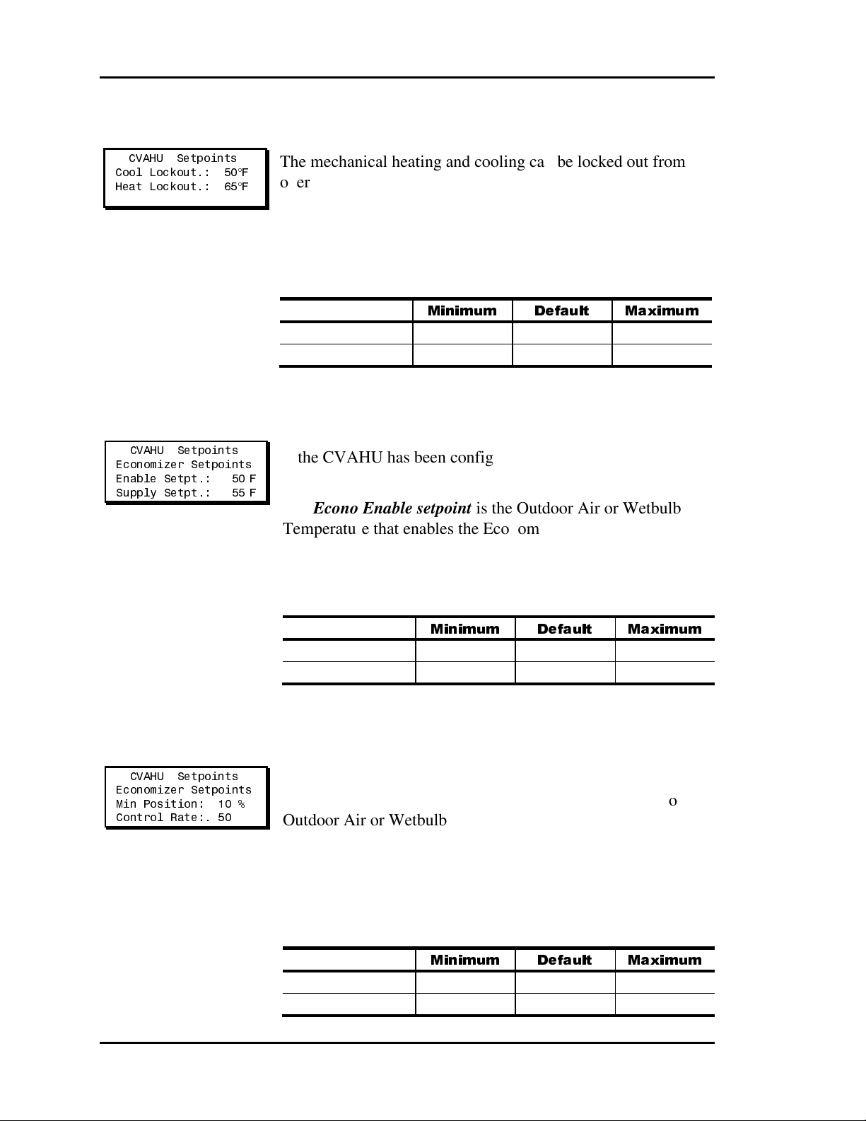
Section 3 Auto-Zone CV & CV-EX
Setpoint Screen #10
CVAHU Setpoints
Cool Lockout.: 50°F
Heat Lockout.: 65°F
The mechanical heating and cooling can be locked out from
operating based on the Outdoor Air Temperature. If the
Outdoor Air Temperature is above the Heating Lockout, no
heating stages are allowed to activate or remain on if they are
already ON. If the Outdoor Air drops below the Cooling
Lockout, no cooling stages are allowed to activate or remain on
if they are already ON.
Cool Lockout -40°F 50°F 90°F
Heat Lockout 30°F 65°F 99°F
Setpoint Screen #11
CVAHU Setpoints
Economizer Setpoints
Enable Setpt.: 50°F
Supply Setpt.: 55°F
If the CVAHU has been configured for Economizer Control,
this screen will appear.
The Econo Enable setpoint is the Outdoor Air or Wetbulb
Temperature that enables the Economizer to open past its
minimum position setpoint to control Supply Air Temperature.
The Supply Setpt is the Supply Air Temperature the
Economizer tries to maintain.
Enable Setpt -40°F 50°F 99°F
Supply Setpt 50°F 55°F 90°F
Minimum
Minimum
Default
Default
Maximum
Maximum
Setpoint Screen #12
CVAHU Setpoints
Economizer Setpoints
Min Position: 10 %
Control Rate:. 50
3-20 Programming
The Min Econo % is the position the economizer holds during
occupied mode when it is not enabled for operation due to
Outdoor Air or Wetbulb Temperature.
During economizer control, the economizer damper is allowed
to move open or closed, as required, at a rate controlled by this
value. Use this to speed up or slow down the operation of your
economizer. The larger the number, the slower the damper
moves.
Minimum
Default
Maximum
Min Position 0 % 10 % 100 %
Control Rate 1 50 90
Page 65

Auto-Zone CV & CV-EX Section 3
Setpoint Screen #13
CVAHU Setpoints
Economizer Setpoints
Min Voltage: 0.0 v
Max Voltage: 10.0 v
You can set the voltages required to open and close the damper.
Some actuators use a 2-10 VDC signal instead of 0-10 VDC.
If the system is not configured for Economizer Control, no
economizer setpoint screens will appear.
Min Voltage 0.0 VDC 0.0 VDC 10.0 VDC
Max Voltage 0.0 VDC 10.0 VDC 10.0 VDC
Setpoint Screen #14
CVAHU Setpoints
Fan Starting Delay
Multiplier...: 10
If there are several air handling units on a system and you don’t
want them to all start at the same time when going into the
occupied mode or after a power outage, you can input a Fan
Starting Delay Multiplier. The multiplier is multiplied times
the address number of the unit and this becomes the number of
seconds this unit waits before starting the fan. For example, if
the Multiplier is 5 and this unit is at address #18, then the time
delay will be 90 seconds.
Multiplier 0 0 30
Minimum
Minimum Default Maximum
Default
Maximum
Setpoint Screen #15
Sensor Rdg Offset
ZNT.: 73.6 0.0
SAT.: 76.5 0.0
OAT.: 70.2 0.0
Programming 3-21
The Thermister Type III Sensor readings can be calibrated.
Enter Positive values to increase the reading or Negative values
to decrease the reading. The Outdoor Air calibration offset only
applies to the CVAHU that has the sensor installed. It has no
effect on the Global Broadcast value of Outdoor Air.
Minimum Default Maximum
Zone Sensor ZNT -100.0°F 0.0°F +100.0°F
Supply Sensor SAT -100.0°F 0.0°F +100.0°F
Outdoor Sensor OAT -100.0°F 0.0°F +100.0°F
Page 66
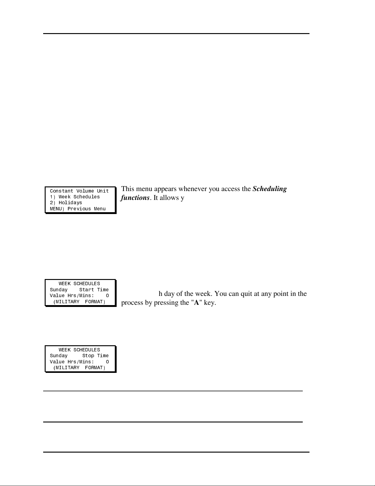
Section 3 Auto-Zone CV & CV-EX
CV Controller
Scheduling and Holidays
The Constant Volume AHU controllers contain their own built-in scheduling capability
for calculating Occupied/Unoccupied periods. All schedules are entered in 24-Hour
Military Format.
See the Constant Volume Menu Operations Screen for information on how to access
these programming functions.
Scheduling/Holiday Menu
Constant Volume Unit
1) Week Schedules
2) Holidays
MENU) Previous Menu
This menu appears whenever you access the Scheduling
functions. It allows you to choose between schedules or
holidays.
Week Schedules
Start Time
WEEK SCHEDULES
Sunday Start Time
Value Hrs/Mins: 0
(MILITARY FORMAT)
Stop Time
WEEK SCHEDULES
Sunday Stop Time
Value Hrs/Mins: 0
(MILITARY FORMAT)
The screens will step through the Start Time and then the Stop
Time for each day of the week. You can quit at any point in the
process by pressing the "A" key.
All times are in 24-hour format, so 5:00 PM would be entered
as 1700.
If both the Start and Stop Times are ZERO, the schedule is in a
Continuous OFF mode.
If both the Start and Stop Times are 2359, the schedule is in a
Continuous ON mode.
Note: The second line displays which day of the week is currently being
programmed. This automatically increments as you finish the Stop Time
and continues to the next Start Time screen.
3-22 Programming
Page 67
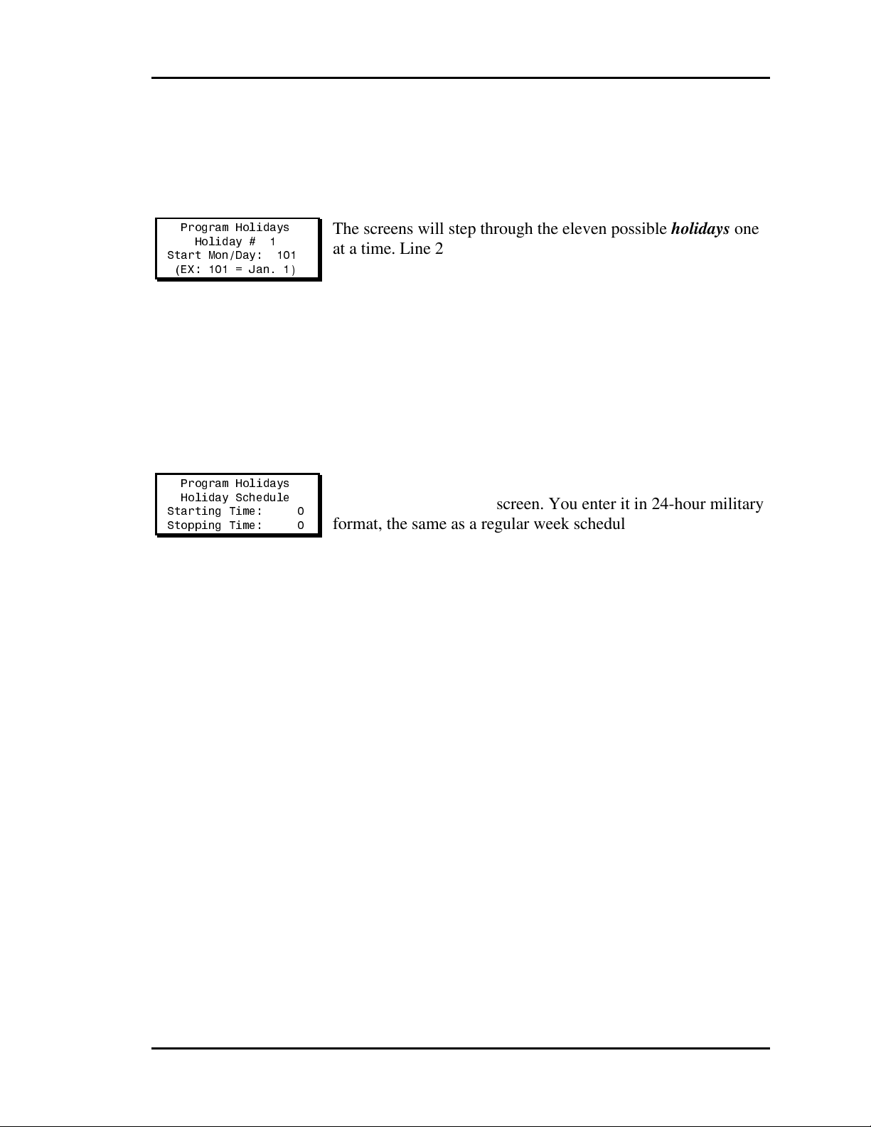
Auto-Zone CV & CV-EX Section 3
Holidays
Holiday Day Selection
Program Holidays
Holiday # 1
Start Mon/Day: 101
(EX: 101 = Jan. 1)
The screens will step through the eleven possible holidays one
at a time. Line 2 shows which holiday is currently being
programmed.
Remember to combine the month and day into a single fourdigit value.
EXAMPLE: 0704 = July 4th
1225 = December 25th
Holiday Start / Stop Times
Program Holidays
Holiday Schedule
Starting Time: 0
Stopping Time: 0
The eleven holidays all use the same Start and Stop time
which you enter on this screen. You enter it in 24-hour military
format, the same as a regular week schedule.
Programming 3-23
Page 68
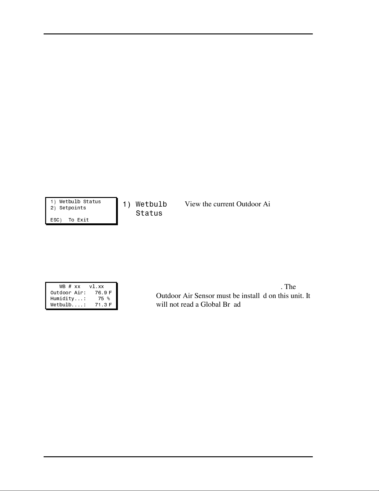
Section 3 Auto-Zone CV & CV-EX
Economizer Module
(Wetbulb) Read/Reset
Operations
If the Unit ID you entered was for the Economizer Module, the following menu will
appear. Any references in this section to wetbulb are referring to the Economizer Module.
Wetbulb Menu
1) Wetbulb Status
2) Setpoints
ESC) To Exit
1) Wetbulb
Status
2) Setpoints
View the current Outdoor Air
Temperature, Humidity, and calculated
Wetbulb Temperature.
View or change any of the available
setpoints for this Economizer Module.
Wetbulb Status
WB # xx vl.xx
Outdoor Air: 76.9°F
Humidity...: 75 %
Wetbulb....: 71.3°F
Line 2 - Current Outdoor Air Temperature reading. The
Outdoor Air Sensor must be installed on this unit. It
will not read a Global Broadcast of the Outdoor Air
Temperature from another controller.
Line 3 - Current Outdoor Relative Humidity.
Line 4 - Current calculation of the Wetbulb Temperature.
3-24 Programming
Page 69
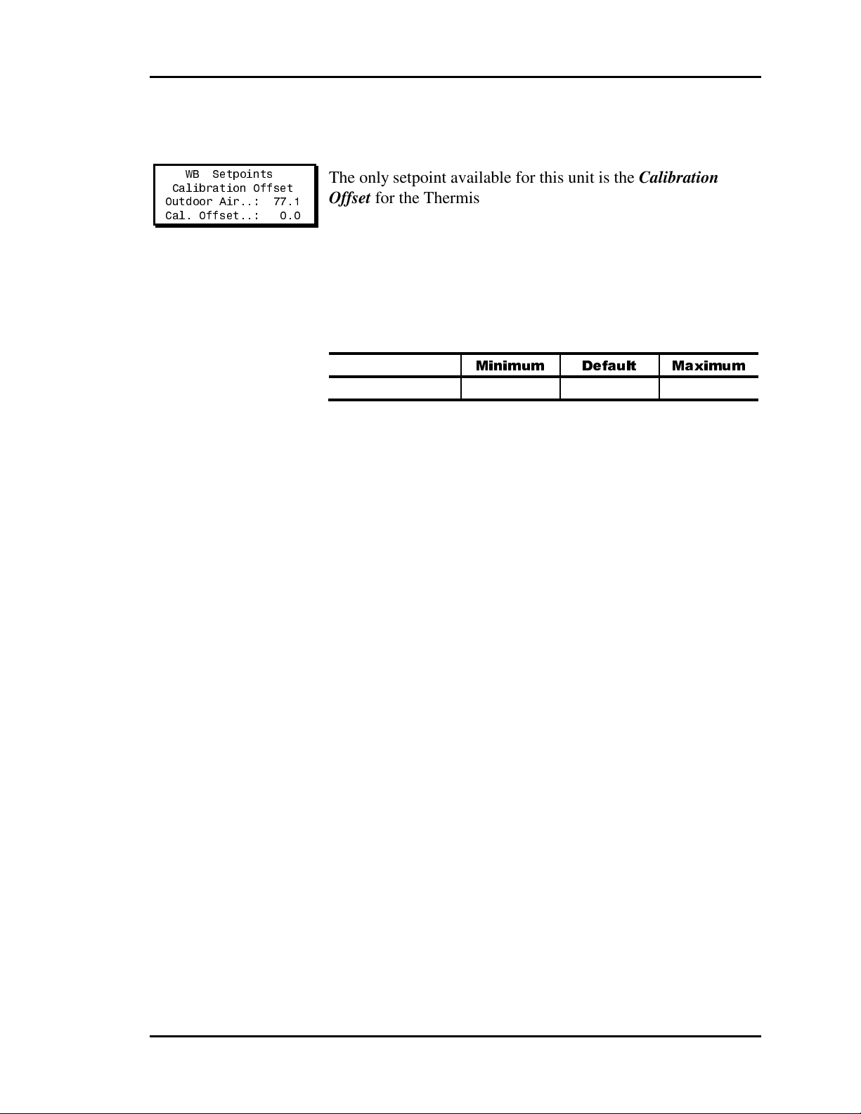
Auto-Zone CV & CV-EX Section 3
Wetbulb Setpoints
WB Setpoints
Calibration Offset
Outdoor Air..: 77.1
Cal. Offset..: 0.0
The only setpoint available for this unit is the Calibration
Offset for the Thermistor Outdoor Air Temperature Sensor. If
location or other factors are causing the Outdoor Air
Temperature reading to be incorrect, you can adjust the reading
up or down with this offset. Line 2 shows the current
temperature when you first enter this screen, but it is not
dynamically updated after the offset is changed. You will need
to exit this screen and then return to this screen to see the effect
of the entered offset.
Minimum
Default
Maximum
Cal. Offset -100.0°F 0.0°F 100.0°F
Programming 3-25
Page 70

Section 3 Auto-Zone CV & CV-EX
System Manager Keypad
Operations Summary
vX.XX
1 Friday Operations
03/20/09 09:46 AM
Outdoor Air 78.0°F
1) View/Change Zone
2) View Alarms
MENU) Full Access
ESC) Main Screen
SYSTEM ALARM STATUS
Clear Alarms? YES
To Change Response
Use Left/Right Arrow
SYSTEM ALARM STATUS
Alarm @ Unit ID 118
1) Set Time & Date
2) Read/Reset Units
3) New Passcodes
4) Rebuild Alarm Map
Program Time/Date
Day (Sunday=0): 1
Enter Hr. (0-23): 9
Enter Minutes : 53
Program Time/Date
Month (1-12): 9
Day (1-31): 18
Year (00-99): 09
Enter New Passcode
Level 1.....: XXXX
Clearing Old Map
....................
................
Level 2.....: XXXX
[Must Be 4 Digits]
View/Change
[ Enter Unit ID# ]
Selected Unit: 101
Constant Volume Unit
Temperature: 75.4°F
Cooling SP.: 75°F
Heating SP.: 72°F
Read/Reset
[ Enter Unit ID# ]
Selected Unit: 101
1) CVAHU Status
2) CVAHU Setpoints
MENU) Next Menu
ESC) To Exit
1) Wetbulb Status
2) Setpoints
ESC) To Exit
Daylight Savings
Adjustments Enabled
Use Left/Right Arrow
Building New Map
Loop: 1
Unit: 1
FOUND
Alarm Unit Map Built
Press Any Key To
Continue
1) Schedules
2) Force Modes
MENU) Previous Menu
3-26 Programming
Page 71

Auto-Zone CV & CV-EX Section 3
Index
12-Hour Format .................................... 6
2359
Start and Stop Times....................... 22
24-Hour Format .................................. 22
24-Hour Military Format ................ 6, 22
50 to 90 Degrees ................................... 4
Address Entry
Read/Reset ...................................... 10
Addresses
Entering............................................. 3
Addressing
MiniLinks........................................ 10
Adjustments Disabled ........................... 7
Adjustments Enabled ............................ 7
AHU.................................................... 12
Alarm
Mech Cooling Alarm ...................... 15
Zone Heating Alarm........................ 15
Alarm
Address Locations............................. 5
Clearing............................................. 5
Condition .......................................... 2
Indicator ............................................ 9
LED................................................... 2
Map ................................................... 9
Polling............................................... 9
Alarms
Bad Zone Sensor ............................. 15
Binary Input Alarm ......................... 15
Clearing............................................. 5
Dirty Filter Alarm ........................... 15
Mech Heating Alarm....................... 15
Zone Cooling Alarm ....................... 15
Auto Mode .......................................... 11
Bad Zone Sensor!................................ 15
Binary Input ALARM ......................... 15
Building New Map................................ 9
Calibration Offset................................ 25
Changeover Delay Timer.................... 18
Clearing Old Map ................................. 9
Communications
LED................................................... 2
Constant Volume AHU
Operating Modes, View .................. 12
Setpoints, View or Change ............. 12
Temperatures, View........................ 12
Continuous Day Mode ........................ 11
Continuous Night................................ 11
Continuous OFF Mode ....................... 22
Continuous ON Mode......................... 22
Continuous or Constant
Fan Mode ........................................ 19
Control Rate........................................ 20
Cool Lockout ...................................... 20
Cool Staging........................................ 18
Cooling Locked Out............................ 14
Cooling Mode
CV Controller.................................. 13
Cooling Off ......................................... 18
Cooling Setpoint
CV Controller.................................. 13
Cooling Setpoints.................................. 3
Cooling Stages Setpoints .................... 17
Current Outdoor Air Temperature ...... 24
Current Outdoor Relative Humidity ... 24
Current Year.......................................... 7
CV Controller
Address ............................................. 3
Force Modes.................................... 11
Holidays .......................................... 22
Read/Reset Operations.................... 12
Scheduling....................................... 22
Setpoints.......................................... 16
Software Version ............................ 13
Status............................................... 13
CVAHU .............................................. 12
Economizer Damper ....................... 14
Force Modes.................................... 12
Schedules ........................................ 12
Setpoints.......................................... 12
Status............................................... 12
Programming 3-27
Page 72

Section 3 Auto-Zone CV & CV-EX
Cycle with Heating or Cooling
Fan Mode ........................................ 19
Date
Programming..................................... 7
Day of the Month .................................. 7
Day/Night Mode ................................. 11
Daylight Savings Adjustments.............. 7
DEC....................................................... 1
Default Level 1 Passcode...................... 8
Default Level 2 Passcode...................... 8
Dirty Filter Alarm ............................... 15
Econo Enable Setpoint........................ 20
Economizer
Control Rate.................................... 20
Min Position.................................... 20
Economizer Control ............................ 20
Economizer Damper
CVAHU .......................................... 14
Economizer Module
Read/Reset Operations.................... 24
Economizer Operation
Setpoint ........................................... 19
Economizer Setpoint
Max Voltage.................................... 21
Min Voltage .................................... 21
ENTER.................................................. 1
Entering Passcodes................................ 4
External Clock .................................... 19
Fan Off ................................................ 14
Fan On................................................. 14
Fan Only Mode ................................... 11
Fan Starting Multiplier........................ 21
Force Modes
CV Controller.................................. 11
CVAHU .......................................... 12
Forced Fan Only Mode
CV Controller.................................. 13
Forced Occupied
CV Controller.................................. 13
Forced Unoccupied
CV Controller.................................. 13
Full Access............................................ 3
Full Access Menu ................................. 6
Full System Access
Menu ................................................. 6
Function
LCD/Keypad ..................................... 1
Global Broadcast................................. 19
Heat Lockout....................................... 20
Heat Staging........................................ 18
Heating Locked Out............................ 14
Heating Mode
CV Controller.................................. 13
Heating Off ......................................... 18
Heating Setpoint
CV Controller.................................. 13
Heating Setpoints.................................. 3
Heating Stages..................................... 17
Setpoints.......................................... 17
Holiday Active
CV Controller.................................. 13
Holiday Day Selection ........................ 23
Holiday Start and Stop Time............... 23
Holidays
CV Controller.................................. 23
Internal Clock...................................... 19
Internal Schedules............................... 11
Internal Week Schedule ...................... 19
Keypad Functions ................................. 1
Keypad Operations Summary ............. 26
LCD/Keypad Operations....................... 1
LED Alarm Indicator ............................ 9
LED Indicators...................................... 2
LEDs
Alarm Condition ............................... 2
Communications ............................... 2
Transfers ........................................... 2
LEFT/RIGHT........................................ 1
Level 1 User...................................... 3, 8
Level 2 User...................................... 3, 8
Main Screen ...................................... 2, 3
Main User Menu ............................... 2, 3
Max Voltage........................................ 21
Mech Cooling ALARM ...................... 15
Mech Heating ALARM ...................... 15
MENU................................................... 1
Menu Items
Full Access........................................ 3
Main Screen ...................................... 3
View Alarms ..................................... 3
3-28 Programming
Page 73

Auto-Zone CV & CV-EX Section 3
View/Change..................................... 3
View/Change Zone ........................... 3
Menus
Full System Access ........................... 6
Holiday Day Selection .................... 23
Scheduling/Holiday......................... 22
Week Schedules .............................. 22
Wetbulb........................................... 24
Min Econo % ...................................... 20
Min Position........................................ 20
Min Voltage ........................................ 21
MiniLinks
Addressing ...................................... 10
MINUS.................................................. 1
Month.................................................... 7
Neutral Mode
CV Controller.................................. 13
New Passcodes...................................... 8
No Alarms........................................... 15
No Lockouts Active ............................ 14
Occupied Cooling
Setpoints.......................................... 16
Occupied Heating
Setpoint ........................................... 16
Occupied Mode................................... 11
Operating Modes................................. 11
Outdoor Air Calibration Offset........... 21
Outdoor Air Sensor ............................. 24
Outdoor Air Temperature.................... 25
CV Controller.................................. 14
Outdoor Relative Humidity................. 24
Outdoor Sensor OAT .......................... 21
Passcodes
Entering............................................. 4
Entering New .................................... 8
Polling
for Units ............................................ 9
Powerup ................................................ 9
Programming
Passcodes .......................................... 8
Programming Date ................................ 7
Programming Time ............................... 6
Push-button Override
CV Controller.................................. 13
Read/Reset
Address Entry.................................. 10
Read/Reset Capabilities ........................ 3
Read/Reset Operations
CV Controller.................................. 12
Economizer Module........................ 24
Wetbulb........................................... 24
Read/Reset Units................................. 10
Real Time Clock ................................. 19
Real Time Clocks.................................. 6
Rebuild Alarm Map .............................. 9
RS-485 Communications Plug.............. 9
Schedules
CVAHU .......................................... 12
Start Time........................................ 22
Stop Time........................................ 22
Scheduling
CV Controller.................................. 22
Scheduling/Holiday Menu .................. 22
Screens
Alarm Address Locations.................. 5
Clear Alarms ..................................... 5
Constant Volume Status.................... 4
CV Controller Force Modes............ 11
Entering Passcodes............................ 4
Full System Access ........................... 6
Holiday Day Selection .................... 23
Main .................................................. 2
New Passcodes.................................. 8
Read/Reset Units............................. 10
Rebuild Alarm Map .......................... 9
Scheduling/Holiday......................... 22
Set Time & Date ............................... 6
View Alarms ..................................... 5
View/Change Zone ........................... 3
Week Schedules .............................. 22
Wetbulb........................................... 24
Sensor Slide Adjust
CV Controller.................................. 13
Sensor Slide Adjustment..................... 17
Set Time & Date ................................... 6
Programming 3-29
Page 74

Section 3 Auto-Zone CV & CV-EX
Setpoints................................................ 2
Cooling.............................................. 3
CV Controller.................................. 16
Heating.............................................. 3
Wetbulb..................................... 24, 25
Setpoints, Entering
Changeover Delay Timer................ 18
Cooling Lockout ............................. 20
Cooling Stages ................................ 17
Economizer Control ........................ 20
Economizer Operation .................... 19
Fan Mode ........................................ 18
Fan Starting Multiplier.................... 21
Heating Lockout.............................. 20
Heating Stages................................. 17
Min Econo % .................................. 20
Occupied Cooling ........................... 16
Occupied Heating............................ 16
Sensor Slide Adjustment................. 17
Slide Effect...................................... 17
SP Deadband................................... 17
Staging Delay Period....................... 18
Staging Delay Period, Heating........ 18
Unoccupied Cooling Setup ............. 16
Unoccupied Heating Setback.......... 16
Slide Effect Setpoint ........................... 17
Software Version
CV Controller.................................. 13
SP Deadband Setpoint......................... 17
Staging Delay Period
Cooling............................................ 18
Heating Stages................................. 18
Start and Stop Times
2359................................................. 22
Zero ................................................. 22
Start Time............................................ 22
Status..................................................... 2
Wetbulb........................................... 24
Stop Time............................................ 22
Summary
Keypad Operations.......................... 26
Supply Air Temperature
CV Controller.................................. 14
Supply Sensor SAT............................. 21
Supply Setpt........................................ 20
System Manager
Keypad .............................................. 1
Keypad Operations Summary ......... 26
Temperature
50 to 90 Degrees ............................... 4
Setpoints............................................ 4
Wetbulb........................................... 24
Thermister Type III Sensor ................. 21
Thermistor Outdoor Air Temperature
Sensor.............................................. 25
Time
12-Hour Format ................................ 6
24-Hour Military Format ............ 6, 22
Continuous OFF Mode ................... 22
Continuous ON Mode..................... 22
Daylight Savings............................... 7
Programming..................................... 6
Real Time Clocks.............................. 6
Transfers
LED................................................... 2
Unit
Polling............................................... 9
Unit ID .................................................. 3
Unoccupied Cooling Setup Setpoint... 16
Unoccupied Heating
Setback Setpoint.............................. 16
Unoccupied Mode
CV Controller.................................. 13
Unoccupied Mode............................... 11
UP/DOWN............................................ 1
View Alarms ......................................... 3
View Alarms Screen ............................. 5
View/Change......................................... 3
View/Change Zone ............................... 3
Week Schedules .................................. 22
Wetbulb
Read/Reset Operations.................... 24
Menu ............................................... 24
Setpoints.................................... 24, 25
Status............................................... 24
Wetbulb Temperature ......................... 24
CV Controller.................................. 14
Zero
Start and Stop Times....................... 22
Zone Cooling ALARM....................... 15
3-30 Programming
Page 75

Auto-Zone CV & CV-EX Section 3
Zone Heating ALARM ....................... 15
Zone Sensor O.K................................. 15
Zone Sensor ZNT................................ 21
Zone Temperature................................. 3
CV Controller.................................. 13
Programming 3-31
Page 76

Section 3 Auto-Zone CV & CV-EX
Notes
3-32 Programming
Page 77

Section 4
Table of Contents
Communications Overview.............................................. 1
How It Works...................................................................................................................1
CV System .......................................................................................................................2
CV-EX System.................................................................................................................3
CommLink IV..................................................................................................................4
CommLink IV DIP Switch Setting ..................................................................................5
MiniLink ..........................................................................................................................6
System Manager...............................................................................................................7
CV Controller Communications ......................................................................................8
CV Controller Address Switches ....................................................................................9
CV and CV-EX System Communications Checklist.....................................................10
CV Controller Overview ................................................. 11
How It Works.................................................................................................................11
CV Controller Inputs & Outputs....................................................................................12
CV Controller Wiring ....................................................................................................14
Startup & Commissioning.............................................. 15
Procedures......................................................................................................................15
CV & CV-EX Worksheet ..............................................................................................17
Troubleshooting............................................................. 18
General Communications...............................................................................................18
Blink Codes....................................................................................................................19
Communications Loops .................................................................................................20
CV Controller.................................................................................................................32
Room Sensor..................................................................................................................33
Driver Chip Replacement ..............................................................................................35
Index .............................................................................. 37
Start-Up & Troubleshooting
Page 78

Section 4
Table of Figures & Tables
Figure 4-1: CV System Communications Wiring .........................................................2
Figure 4-2: CV-EX System Communications Wiring...................................................3
Figure 4-3: CommLink IV Wiring.................................................................................4
Figure 4-4: CommLink IV DIP Switch Setting .............................................................5
Figure 4-5: MiniLink Wiring and Addressing...............................................................6
Figure 4-6: System Manager Component Location & Wiring ......................................7
Figure 4-7: CV Controller Component Locations.........................................................8
Figure 4-8: CV Controller Addressing..........................................................................9
Figure 4-9: Typical CV Controller Wiring Diagram...................................................14
Table 4-1: Diagnostic LED Blink Codes.....................................................................19
Table 4-2: Temperature Sensor Resistance .................................................................34
Figure 4-10: Driver Chip Locations............................................................................35
Figure 4-11: General Chip Replacement Procedures .................................................36
Start-Up & Troubleshooting
Page 79

Auto-Zone CV & CV-EX Section 4
Communications
Overview
Perhaps no other portion of the system seems as difficult to diagnose as the communications loop, yet it really can be quite simple if you understand how it works. In fact, much
of the troubleshooting can be done by simple observation. We will lead you through the
system functions and then provide you with detailed instructions for checking each piece
of equipment.
How It Works
Auto-Zone uses a token-passing loop architecture, which means in simple terms that an
“electronic message” called a token is passed from controller to controller in a roundrobin fashion. A controller must wait to receive the token before it can send or request
any data. Only one device on each loop is capable of sending the token, and this device is
considered the loop master. The loop master varies depending on the type of system and
the installed options. For the CV system, the loop master is the CommLink. The
CommLink must be connected to the system or the communications will not function. For
the CV-EX system, the Local Loop master for the CV controllers is the MiniLink, and the
Network Loop master is the CommLink.
Note: It is very important to know which device is the loop master on the loop you are
troubleshooting.
In order for the loop master to communicate with the various devices on that loop, each
must have a unique address. With the CV or CV-EX system, each CV controller on the
local loop must have its own address from 1 to 30. For the CV system, this is all that is
required. For the CV-EX system, in addition to each CV controller being addressed, the
MiniLink on each local loop must have its own unique address between 1 and 4. Please
see Figure 4-5 for address switch setting information.
Start-Up and Troubleshooting 4-1
Page 80

Section 4 Auto-Zone CV & CV-EX
CV System
The standard CV system has only one communications loop. If you are using the CV-EX
System (for systems with more than 30 CV Controllers), please see the next page - CV-
EX System. The CommLink IV is always the master on the CV system loop. You must
be sure the CommLink IV is connected and functioning if you are troubleshooting the
communications loop. The CommLink IV jumper switch must be set for single loop
operation when used with the CV system. See Figure 4-1 for communications wiring
connections and Figure 4-4 for jumper switch settings.
CV ControllerCV Controller
System Manager
The System Manager Can Be
Connected Anywhere
On The Loop
CV Controller
CV Controller
CommLink IV
The CommLin k IV Is R equired Fo r
All Systems. The IP Module,
Remote Link II, And Computer Are
Optional On All Systems. All
Computers Require Installation of
Prism Graphical User Interface
Software
Ethernet Cable To Router
All Components Shown Inside This Box Are Optional
End Of Loop
The Comm Loop
Routing Does Not
Have To Follow
The Board Address Sequence
USB Cable To Computer
Loop Start
Optional IP Module
Installs Into CommLink IV
And Provides LAN And Internet
Communicati ons
With The Control System
Ethernet Rout er
(By Others)
When IP Module
Option Is Used
Computer
(Optional)
Comm Loop
RS-485
9600 Baud
Serial Cable To Remote Link
Phone Cable To Telephone
Wall Outlet Jack
Optional Remote Link II
Connects to CommLink IV And
Provides Alarm Call-Outs. A
Second Remote Link Is Required If
Connection To Job Site Is Desired
From Remote Computer.
CV Controller
CV Controller
Figure 4-1: CV System Communications Wiring
4-2 Start-Up and Troubleshooting
Page 81
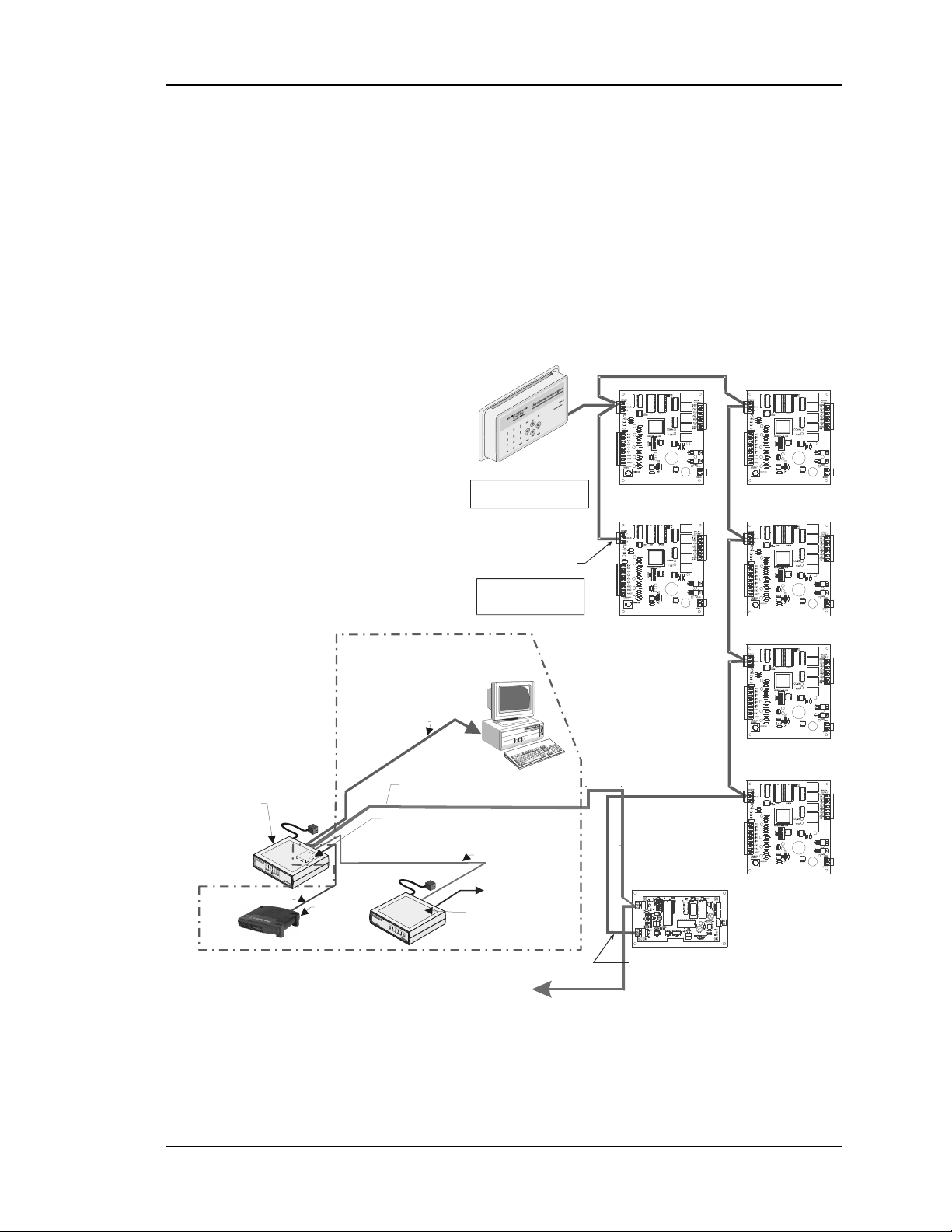
Auto-Zone CV & CV-EX Section 4
CV-EX System
See Figure 4-2. The CV-EX system has two types of communications loops. The loops
which the CV controllers are connected to are called the Local Loops. The MiniLink is
always the loop master on the CV-EX local loop. You must be sure the MiniLink is
connected, powered up, and functioning if you are troubleshooting a Local communications loop. The other type of loop on the CV-EX system is called the Network Loop. This
loop connects all the MiniLinks together and then ties into the CommLink IV which is
the Network Loop Master. The CommLink IV jumper switch must be set for multiple
loop operation when used with the CV-EX system. See Figure 4-4 for the correct jumper
switch setting.
CV ControllerCV Controller
System Manager
The System Manager Can Be
Connected Anywhere
On The Local Loop
CV Controller
CV Controller
CommLink IV
The CommLink I V Is Required For
All Systems. The IP Module,
Remote Link II , And Computer Are
Optional On All Systems. All
Computers Require Installation of
Prism Graphica l User Interface
Software
Ethernet Cable To Router
All Components Shown Inside This Box Are Optional
USB Cable To Computer
Ethernet Router
(By Others)
When IP Module
Option Is Used
Network Loop Start
Optional IP Module
Installs Into CommLink IV And
Provides LAN And Inter net
Communications
With The Control System
Remote Link Is Requi red If Connection To
Job Site Is Desired From Remote Computer.
End Of Local Loop
The Comm Loop
Routing Does Not
Have To Follow
The Board Address Sequence
Computer
(Optional)
Serial Cable To Remote Link
Phone Cable To Telephone
Wall Outlet Jack
Optional Remote Link II
Connects to CommLink IV And
Provides Alarm Call-Outs. A Second
Connect To
Network Loop
Connection On
Next MiniLink
Network Loop
RS-485
19200 Baud
Local Loop
RS-485
9600 Baud
MiniLink
Local Loop Start
CV Controller
CV Controller
Figure 4-2: CV-EX System Communications Wiring
Start-Up and Troubleshooting 4-3
Page 82

Section 4 Auto-Zone CV & CV-EX
C
g
CommLink IV
As previously described, the CommLink is the Local Loop Master for the CV system and
the Network Loop Master for the CV-EX system. For both systems to function, the
CommLink must be set to the correct operation mode by setting the correct jumper
position on the CommLink board. Also, the CommLink communications must be wired
correctly to the system and connected correctly to the computer (if used) and Remote
Link II. It must also be powered up in order for either system to communicate. See Figure
4-3 for information.
USB Switch
Should Be Set
To No rm al
ommLink IV
Communications Interface
10/100
ETHERNET
DIAG
ACT LNK
Optional Items Not
Required For
CommLink Only
Installations
Notes:
1) Use 18-Gauge Minimum, 2-Conductor Twisted Pair With Shield Cable Belden #82760 Or Equivalent
(Not Included) To Connect The CommLink IV To The MiniLink On Network Loop Or Controller Or System Mana
2) For Direct Connection Via USB, Your Computer Must Have An Unused USB Port Available. Drivers
For Your USB Port Are Provided On A CD Supplied With The CommLink IV And Will Need To Be
Installed On Your Computer In Order For It To Function Correctly. Please Refer to the CommLink IV
Installation Technical Guide Form: WM-CLIV-TGD
3) The CommLink IV Cannot Communicate With The Control System Through Its Ethernet Port And
USB Port At The Same Time.
4) All Wiring Must Conform To Applicable Federal, State & Local Electrical Wiring Codes.
.
USB Cable (Included). Connect
This Cable To Your Computer USB
Port For Directly Connecting To
CommLink IV. Also Used For
Advanced Configuration of
CommLink IV.
Molded Modem Cable.
Part #HZ000098
Supplied With RemoteLink II
Optional - Prefabricated Ft. Long CAT5
Ethernet Cable (Included With Optional OE41502 IP Module Kit).
Ethernet Router On Your LAN.
Ethernet Cable Is Required, You Will Need To
Obtain (From Others) And Install An Ethernet
Cable Of The Required Length For Your
Installation.
10
Connect To A 10/100 Base-T
If A Longer
COMPUTER
Normal
Config
USB
When An Optional Remote
Link Is Used, Connect This
Cable To CommLink IV And
Remote Link As Shown. Cable
Is Included With Remote Link.
Which Is Supplied With The CommLink IV.
USB
MODEM
RS-232
Female
25 Pin
Male
TGR
485 LOOP
9Pin
Serial #
GND
24V
POWER
24 VAC Power
18-Gauge, 2-Conductor
With Shield (Not Included)
Connect To The Controller Or System
Manager On Local Loop Or MiniLink
On Network Loop. See Note 1.
120 to 24 VAC Power Pack
(Included) Connect To 120/1/60 Duplex
Receptacle (By Others)
If Desired A 24 VAC Transformer
Included)
Rated At 12 VA Minimum May Be
Used Instead Of The Supplied Power Pack.
Use 18 Gauge Minimum 2 Conductor Wire
Between The Transformer & CommLink IV
Terminals.
WARNING!
With Your CommLink, Do Not Have Your
Ethernet Connection And USB Connection
Connected At The Same Time. This Could
Cause Unreliable Communications.
If You Are Using The IP Module
(Not
er On Local Loop.
Figure 4-3: CommLink IV Wiring
4-4 Start-Up and Troubleshooting
Page 83
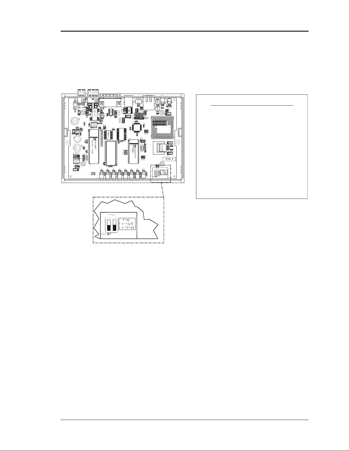
Auto-Zone CV & CV-EX Section 4
CommLink IV DIP Switch Setting
CommLink IV Communication Settings
The SW1 DIP Switch Located On The Circuit Board Inside
The CommLink IV Housing Must Be Set Correctly For
Your Specific Application In Order To Function Properly.
The CommLink IV Is Factory Set For Multiple Loop
Applications.
To Check And/Or Set The SW1 Dip Switch, First Remove
The (2) Enclosure Screws That Hold The Top And Bottom
Of The CommLink IV Enclosure Together. Remove The
Top Half Of The Enclosure To Access The Circuit Board
And Dip Switches.
The DIP Switch Setting Should Be Set To “Multiple”
SW1
For The Auto-Zone System
Replace The CommLink IV Cover And Secure The
Enclosure Halves Back Together With The (2) Enclosure
Screws That Were Previously Removed.
CV-EX .
WattMaster Controls Inc.
COMMLINK IV
YS102074
REV6
MADE IN USA
ALTERA
EPM3032
DIP Switch 1 & 2 Off =
Multiple Loop Communications
Required Setting For Auto-Zone CV-EX System
Figure 4-4: CommLink IV DIP Switch Setting
Start-Up and Troubleshooting 4-5
Page 84

Section 4 Auto-Zone CV & CV-EX
C
MiniLink
The MiniLink communications interface is only required when you are installing a CVEX system. It is not required for the CV system. Its address switch must be set correctly,
it must be correctly wired into the system, and it must be powered up in order for the CVEX system to operate correctly. The address switches must be set and the power cycled in
order for the address to be recognized by the system. See Figure 4-5 for MiniLink wiring
and addressing.
onnect To Next
MiniLink And/Or
CommLink On
Network Loop
Network Loop
RS-485
19200 Baud
(See Note 3).
All Communication Loop
Wiring Is Straight Through
T
T
SH
R
Local Loop
RS-485
9600 Baud
(See Note 3).
T
SH
SH
R
R
MiniLink Communications Interface
ADD
1
2
NETWORK
T
4
8
SH
16
32
R
T
SH
R
T
SH
R
OFF >
24VAC
LOOP
GND
24VAC
GND
Required VA For Transformer
MiniLink = 10VA Max.
See Note 1.
Line Voltage
Connect To CV
Controller or
System Manager
On Local Loop
Notes:
1.) 24 VAC Must Be Connected So
That All Ground Wires Remain
Common.
2.) All Wiring To Be In Accordance
With Local And National Electrical
Codes And Specifications.
3.) All Communication Wiring To Be
2 Conductor Twisted Pair With
Shield. Use Belden #82760 Or
Equivalent.
Caution!
The MiniLinks Must Have Address Switc hes Set Between 1
And 4 (Up To 4 MiniLinks Are Allowed Per CV-EX System).
The MiniLinks Should Be Addressed In C onsecutive Order
Starting With Address #1. Address #1 Must Be Present On
The Loop For The System To Function.
Note:
The Power To The MiniLink Must Be Removed And
Reconnected After C hanging The Address Switch.
Caution:
Disconnect All Communication Loop W iring
From The MiniLin k Before Removing Power
From The MiniLink. Reconnect Power And Then
Reconnect Communicat ion Loop Wiring.
Address Switch Shown Is
Set For Address 1
Must Be Unique To The Other MiniLinks
On The Network Loop. Loop #1 MiniLink
Loop #2 MiniLink Should Be Addressed
ADD
1
2
4
8
16
32
MiniLink
Address Switch
The Address For Each MiniLink
Should Be Addressed As #1
As #2 Etc.
These Switches Must Be
In The OFF Position
As Shown
Address Switch Shown Is
Set For Address 4
Figure 4-5: MiniLink Wiring and Addressing
4-6 Start-Up and Troubleshooting
Page 85

Auto-Zone CV & CV-EX Section 4
System Manager
The System Manager is the central operator interface for the CV or CV-EX system. It
must also be connected correctly to the communications loop in order to view the system
status and configure or change setpoints. It must be supplied with 24 VAC power in order
to operate. The System Manager does not require addressing. The System Manager is
always connected to the “Local” loop. For the CV system, this is the only loop on the
system. The System Manager can be connected anywhere on the CV communications
loop. In contrast, the CV-EX has two types of loops—the “Network” and “Local” loops.
The System Manager must be connected to the local loop on the CV-EX system. It will
not function correctly if connected to the network loop! See Figure 4-6 for wiring and
component location information for the System Manager.
03/20/09 06:38PM FRI
OCCUPIED
NO ALARMS
System Manager
Required VA For Transformer
System Manager = 25VA Max.
Line Voltage
See Note 1
System Manager
Base
Top
CX1
SYSTEM MANAGER
U1
LD1
YS101806 REV. 1
74HC259
GND
24VAC
LD2
LD3
LD4
LD5
LD6
RN1
LD7
LD8
The Ideal Recommended Locat ion For The System Manager Is As The First
Device On The Local Loop. The System Manager May Be Connected To The
Local Loop At Any Point On The Local Loop.
Notes:
1.) 24 VAC Must Be Connected So
That All Ground Wires Remain
Common.
2.) All Wiring To Be In Accordance
With Local And National Electrical
Codes And Specifications.
U2
R1
R2
PCB80C552-5-16WP
DfD9722V7Y
442860=2/5
X1
C2C1
74HC573
U7
CX7
CX9
V62C518256L-70P
U9
CX13
SS0017
vx.xx 1234
U13
UNIVERSAL SMART DISP. UNIT
DSPY1
EWDOG
U3
PHILIPS
PHILIPS
CX4
RN2
CX8
74HC573
U8
U3
R3
CX5
24C128
U5
D3
R7
CX6
C3
8583
X2
U6
SC1
RAM
TB1
EPROM
R10
D1
CX3
R5
82B715
R6
D2
PJ1
R12
24VAC
CX12
D4
SHLD
GND
T
R
C4
TB2
U12
C11
75176
RS-485
MADE IN
COMM
THE USA
SERIAL #
3.) All Communication Wiring To Be
2-Conductor Twisted Pair With
Shield. Use Be lden #82760 Or
Equivale nt.
DSPY1
SERIAL # :
RV1
R4
See Note 3
VAR1
470uF50v
470uF50v
U10
R8
D6
C5
MC34064A
U11
C7
9936
C8
L1
C6
R9
R11
1000uF10v
1000uF10v
C9
P1
CX10
74HC923
For CV Systems, Connect To Any
CV Controller On The Local Loop
Or To The CommLink. For The
CV-EX System, Connect To Any
Controller On The Local Loop Or
To The Local Loop Terminal On
The MiniLink.
Do Not Connect To The
Network Loop On CV-EX
Systems!
Figure 4-6: System Manager Component Location & Wiring
Start-Up and Troubleshooting 4-7
Page 86

Section 4 Auto-Zone CV & CV-EX
s
Typical
CV Controller Communications
One CV controller is required for each Constant Volume AHU unit to be connected to the
system. As with the communications devices on the system described previously, it must
be wired correctly, and it must be connected to 24 VAC power for the system to function.
Each controller must also be addressed correctly. Improper addressing is one of the most
common mistakes made when installing a CV or CV-EX system. If duplicate addresses
are assigned on the same loop, fluctuating readings will occur. First, one controller’s
setpoints and status will be passed and then the other. This can be a very frustrating error
to find. Another common mistake is flipping (reversing) of the T and R wires on the
communication loop between controllers or other communications devices. Always be
sure to double-check all communication wiring and addressing before initial
commissioning of the system. It is much easier to set the address switch on a controller
prior to installation than after it is installed in a ceiling or rooftop unit control panel. The
address switches must be set and the power cycled in order for the address to be recognized by the system. Please see Figure 4-7 and Figure 4-8 for CV Controller component
location and addressing information.
CPU
Chip
RS-485
Communications
Ter mi na l B loc k
Pin 1
Indicator
RAM
Chip
EPROM
Chip
PAL
Chip
RS-485
Communications
Driver Chip
Communications
LED
Power LED
Diagnostic Blink
Code LED 1
Diagnostic Blin k
Code LED 2
Relay Output
Ter min als
Address Switch
Real Time
Clock Chip
24 VAC
Power Input
Ter min al
Figure 4-7: CV Controller Component Locations
4-8 Start-Up and Troubleshooting
Page 87

Auto-Zone CV & CV-EX Section 4
CV Controller Address Switches
CV Controller Address Switch SettingCV Controller Address Switch Values
Switch Shown Is
Set For Address 5
ADDRESS ADD
Note:
1.) Ignore Any Markings On The Switch Body.
2.) Use The Address Charts Below Or Address Switch
3.) Power To Controller Must Be Turned Off And
SW1
Value Table Above To Determine Correct Switch Setting.
Back On In Order For Switch Settings To Take Effect.
Address Switch Values Are Not
Labeled On The CV Controller
Use The Table Below
Address Switch Values
1
2
4
8
16
32 (Always OFF- Not Used)
TOKEN (Always OFF)
NETWORK (Always ON)
Address Switch Setting Chart For CV Controllers
ADDRESS ADD
ADDRESS ADD ADDRESS ADD ADDRESS ADD ADDRESS ADD
SW1
Address Switch Shown Is
Set For Address 9
Address Switch Values Are
Added Together When The
Rocker Is Pushed Down In
The Direction Of The “ADDRESS
ADD” Arrow Marked On The CV
Controller Circuit Board
ADDRESS
ADD
Controller
Address Switch
ADDRESS
SW1
Address Switch Shown Is
Set For Address 30
ADD
1
SW1
ADDRESS ADD ADDRESS ADD ADDRESS ADD ADDRESS ADD ADDRESS ADD
6
SW1 SW1 SW1 SW1 SW1
ADDRESS ADD ADDRESS ADD ADDRESS ADD ADDRESS ADD ADDRESS ADD
11
SW1 SW1 SW1 SW1 SW1
ADDRESS ADD ADDRESS ADD ADDRESS ADD ADDRESS ADD ADDRESS ADD
16
SW1 SW1 SW1 SW1 SW1
ADDRESS ADD ADDRESS ADD ADDRESS ADD ADDRESS ADD ADDRESS ADD
21
SW1 SW1 SW1 SW1 SW1
ADDRESS ADD ADDRESS ADD ADDRESS ADD ADDRESS ADD ADDRESS ADD
26
2
SW1 SW1 SW1 SW1
7
12
17
22
27
3
8
13
18
23
28
4
9
14
19
24
29 30
5
10
15
20
25
SW1 SW1 SW1 SW1 SW1
Figure 4-8: CV Controller Addressing
Start-Up and Troubleshooting 4-9
Page 88

Section 4 Auto-Zone CV & CV-EX
CV and CV-EX System
Communications Checklist
CV & CV-EX Systems
CV Units on each loop are correctly addressed from 1 to 30
Power has been cycled after changing addresses
There are no duplicate addresses on the loop
CommLink is connected to the communications loop
All CV Controllers are connected to the communication loop
System Manager is connected to the communications loop
All communication wiring is landed correctly, T to T, R to R, and SHLD to SHLD
CommLink is set for single loop operation (on CV System)
CommLink is set for multiple loop operation (on CV-EX System)
CV Controllers are wired to 24 Volt AC power supply
CommLink is wired to 24 Volt AC power supply
All 24 VAC power wiring is landed correctly—24VAC to 24VAC and GND to GND
CommLink is powered up
CV Units are powered up
System Manager is powered up
Additional Checks for the CV-EX System
MiniLinks are correctly addressed from 1 to 4
MiniLink Power has been cycled after changing addresses
There are no duplicate addresses on the loop
All CV Controllers are connected to a Local communications loop
CommLink is connected to the Network communications loop only
System Manager is connected to one of the Local communications loops
Optional Equipment
Personal computer is correctly connected to the CommLink
Prism™ software installed on personal computer
Remote Link II is correctly connected to the CommLink
Remote Link II connected to a working phone line
IP Module is correctly installed in the CommLink
IP Module’s Ethernet cable is connected to router
4-10 Start-Up and Troubleshooting
Page 89

Auto-Zone CV & CV-EX Section 4
CV Controller Overview
How It Works
Initialization
On system power-up, the COMM LED remains extinguished for five seconds. After this
delay, the COMM LED will blink out the address of the controller (Address Switch
Setting). The COMM LED will then extinguish for another five seconds and then begin
to blink for a twenty second startup delay. At the conclusion of this twenty second period,
the COMM LED will begin blinking a diagnostic code every ten seconds. See the Blink
Code section of this manual. The duration of a power-up initialization sequence is
roughly one minute.
During this initialization period, the controller retrieves all operating setpoints from its
non-volatile EEPROM memory and initializes all outputs to an OFF condition.
Operating Summary
At all times, after the conclusion of the initialization sequence, the CV controller
performs a specific set of operating instructions in the following order: (1-7 repeat
continuously)
1. Reads Analog Inputs for Temperatures and Overrides.
2. Checks the RS-485 communications port for any new setpoints from the System
Manager and keeps the status updated for the System Manager.
3. If the push-button override is active, it checks the timer to see if the override
is finished.
4. Calculates the current occupied/unoccupied mode from its internal week
scheduling.
5. Calculates what state the output relays and analog output should be set to.
6. Updates the diagnostic COMM LED blinking.
7. Stores data in the internal trend log if ready for another log.
Start-Up and Troubleshooting 4-11
Page 90

Section 4 Auto-Zone CV & CV-EX
CV Controller Inputs & Outputs
24 VAC Power Connector
This connector provides power to the CV Controller.
24VAC - The “hot” side of the control transformer.
GND - The grounded side of the control transformer. If the secondary of the con-
trol transformer is not grounded, you must still observe polarity if the transformer powers any other device!
Warning: Connect only the GND terminal to the grounded side of a transformer.
Failure to properly observe polarity will result in
damage to the system.
Observe polarity at all points in the system.
Analog Input Descriptions
Input #1 - Space temperature is read on this input. If the room sensor with override is
installed, the input is also monitored for push-button override commands. The pushbutton is only active during unoccupied hours, so a push during occupied hours has no
effect.
Input #2 - This input is only used if a space temperature sensor that has the slide adjust
option is installed. The slide adjust can be used to offset the current heating and cooling
setpoints.
Input #3 - Supply air temperature is read on this input. The supply air reading is used to
detect equipment failure. Once a heating or cooling stage has activated, the supply air has
thirty minutes to change by 5°F or the controller assumes a mechanical failure has
occurred. The supply air also prevents cooling stages from activating if the temperature is
45°F or lower in the cooling mode and prevents heating stages from activating if the
temperature is 140°F or higher in the heating mode.
Input #4 - Outdoor air temperature is read on this input. If you have more than one CV
controller installed on the RS-485 communication loop, only one controller needs this
sensor. The unit that has this sensor will automatically broadcast the outdoor air temperature to all other controllers on the loop.
Input #5 - This input can be used to monitor an alarm contact closure. If the contact is
closed, the alarm is active.
4-12 Start-Up and Troubleshooting
Page 91

Auto-Zone CV & CV-EX Section 4
Note: All temperature sensors must be Thermistor Type III which provides 77°F @
10K Ohms Resistance.
Analog Output Description
Analog Output - This output is used to control the Outdoor Air Damper if you configure
the unit for Economizer control. The output voltage range is user-programmable to cover
all types of proportional actuators. 0 - 10 VDC, 2 - 10 VDC outputs are possible.
Relay Output Descriptions
Output #1 - Main Fan ON/OFF Control
Output #2 - Mechanical Heating / Cooling Stage #1
Output #3 - Mechanical Heating / Cooling Stage #2
Output #4 - Mechanical Heating / Cooling Stage #3
Output #5 - Mechanical Heating / Cooling Stage #4
Any combination of heating and cooling stages may be configured during setup as long as
the required number of outputs does not exceed four.
RS-485 Communications Connector
This connector provides the connection point for the Local Loop RS-485 communications
loop. The wiring consists of a twisted pair of wires with a shield.
T - RS485 (+) Communications terminal
SHLD - Common return wire, this point is internally tied to GND on the
CV Controller.
R - RS485 (-) Communications terminal
Start-Up and Troubleshooting 4-13
Page 92

Section 4 Auto-Zone CV & CV-EX
CV Controller Wiring
CV Controller
1
2
4
8
16
32
TOKEN
NETWORK
Line Voltage
RELAY
OUTPUTS
COM1-3
R1
R2
R3
R4
R5
COM4-5
GND
24VAC
4.) Only One Outside Air
Sensor Is Required Per
System. It May Be
Connected To Any CV
Controller On The System.
If The Wetbulb Module Is
Used, The OA Sensor Must
Be Connected To The
Wetbulb Module.
Constant Volume
Unit Connections
R (24VAC)
G (Fan-On/Off)
Wx or Yx (Htg or Clg Stage x)
Wx or Yx (Htg or Clg Stage x)
Wx or Yx (Htg or Clg Stage x)
Wx or Yx (Htg or Clg Stage x)
TB2
Note:
Up To 4 Stages Of Heating Or
Cooling Or Any Combination Of Each
Is Allow ed And Programma ble Via
The System Manager or Computer
Front End Software. If The Unit Has
Heat, Heating Stages Must Be
Connected To The First Outputs in
Consecutive Order And Cooling
Stages To The Remaining Outputs In
Consecutive Order.
Required VA For Transforme r
Each CV Controller = 20VA Min.
TB1
GND
24VAC
See Note 1 & 2
Line Voltage
Connect To
Next Controller
MiniLink On
Local Loop
Room Sensor
NORMAL
OVR
Mount In HVAC
Unit Supply
Tem p. Sens or
And/Or
W
A
R
M
E
R
C
O
O
L
E
R
Discharge
Air Temp.
Sensor
Air Duct
Switch Supplied
By Others
Auxiliary Alarm
Outside Air
(See Note 4)
All Comm Loop Wiring Is
Straight Thru
T
T
SH
SH
R
R
Local Loop
RS-485
9600 Baud
TMP
GND
AUX
Connection To
AUX Terminal is Reqd
Only When Sensor
Is Specified With
Slide Adjust Option
Input
Y 3
+ 2
COM 1
Economizer
Actuator
(Belimo Shown)
Consult Factory For
Other Manufacturers
Wiring Connections
T
T
SH
SH
R
R
T
SHLD
R
+VDC
AIN 1
AIN 2
AIN 3
AIN 4
AIN 5
GND
GND
AOUT
TB3
EXPANSION T'STAT
Caution:
When Wiring The CV Controller Be Sure To
Disconnect All Communication Loop Wiring
From The CV Controller Before Removing Power
From The CV Controller. Reconnect Power And
Then Reconnect Communication Loop Wiring.
24VAC
GND
See Note 1 & 2
Notes:
1.) 24 VAC Must Be Connected
So That All Ground Wires
Remain Common.
2.) All Wiring To Be In
Accordance With Local And
National Electrical Codes And
Specifications.
3.) All Communication Wiring To
Be 2 Conductor Twisted Pair
With Shield. Use Belden
#82760 Or Equivalent.
Figure 4-9: Typical CV Controller Wiring Diagram
4-14 Start-Up and Troubleshooting
Page 93

Auto-Zone CV & CV-EX Section 4
Startup & Commissioning
Commissioning the system correctly is one of the most important steps in getting a
system installed and functioning with the least amount of problems and in the shortest
length of time.
Procedures
The following is a list of items and reminders that are essential to the successful commissioning of your system. Some of these items have already been discussed in this manual
and are repeated to confirm correct procedures. Familiarize yourself with this installation
manual and the system wiring diagrams before installing!
1) Check to see if you have all of the correct components for your installation.
2) Establish the location for the CommLink Interface first. This is where your
communication cable will begin for the CV & CV-EX systems.
3) Lay out your communication wiring per the instructions in the previous
portion of this manual. For CV Systems, it is only one loop. For CV-EX Systems, there are two communication loops:
4) The Network Loop - This loop originates at the CommLink and interconnects
MiniLinks together.
5) The Local Loop – This loop originates at the MiniLink. All controllers and the
System Manager are connected to this loop.
6) Tip: Using the Auto-Zone color-coded and labeled Communication Cable
ensures a quality installation. It also makes your installation much easier and
makes it less likely that your system will have communications wiring errors!
7) Always refer to the CV and CV-EX Wiring Diagrams for specific wiring
details. Communication cable must always be shielded – no exceptions!
8) Mount controllers in appropriate locations according to their operating
specification.
9) Use the CV and CV-EX Worksheets included in the back of this section or the
ones included with the submittal package to document unit location, descriptions, addressing, and setup. Address controllers according to location and
addressing instructions located in this system manual.
Start-Up and Troubleshooting 4-15
Page 94

Section 4 Auto-Zone CV & CV-EX
Procedures (Continued)
10) With no power connected, wire controller according to wiring diagrams and
in accordance with local codes. Never apply power until you have completed
these procedures in accordance to all system instructions.
11) After completing all wiring connections, unplug the terminals for power and
communications. Always unplug the communications loop first and then the
power. When reconnecting the wiring, connect the power first and then the
communication loop.
12) Repeat Steps 8 through 11 until all devices have been wired and the power
and communication terminals have been unplugged.
13) Install the CommLink and power it up. At this point, you are ready to begin
commissioning of the system. It is preferred, though not necessary, to use a
PC with Prism™ software installed to assist in the commissioning process.
If you are not using a PC, the System Manager is required to be connected
and powered up in order to communicate with the system.
14) For the CV system, start with the first CV controller on the communication
loop. Plug in the Communication terminal and then plug in the Power
terminal. With the CV-EX multiple loop system, start with the MiniLink.
Plug in the Communication terminal and then plug in the Power terminal.
With the CV-EX system, confirm correct addressing of the MiniLink by
verifying its blink code. Then connect the first CV controller on that local
loop and proceed to the next step.
15) Check the CV Controllers for correct communications and addressing by
observing the LED indicator for the blink codes as outlined in the trouble
shooting section of the manual. The blink code will first verify the address
and then the operation. If the address is incorrect, reset the address switch,
and then reapply power to the controller.
16) After each controller is connected and completes its initialization sequence,
use the PC or System Manager to verify communication to that device. If you
cannot communicate, verify wiring, voltages, etc. in accordance with the
trouble-shooting section in the system manual. Do not proceed to the next
device until you are properly communicating with the current device.
17) Continue this process for each CV Controller on the loop and repeat the
process on each loop for the CV-EX system until all controllers are
connected and properly communicating.
Remember that each controller only contains one puff of smoke. Making sure that all
wiring terminations and voltages are correct prior to applying power to a controller will
ensure that you don’t use that one puff up.
4-16 Start-Up and Troubleshooting
Page 95

Auto-Zone CV & CV-EX Section 4
CV & CV-EX Worksheet
Project: ___________________________ Location ___________________________
Stages of Cool: ___ Stages of Heat: ___ Gas Electric Economizer Yes No
Loop: 1 2 3 4 Remote Link Installed Yes No Phone No. ___________
Unit
Unit Description or Location Sensor Type
Address
1
2
3
4
5
6
7
8
9
10
11
12
13
14
15
16
17
18
19
20
21
22
23
24
25
26
27
28
29
30
[S=Sensor] [SO=Sensor w/ Override] [SA=Sensor w/ Setpoint adjust] [SOA=Sensor w/ Override & Setpoint Adj.
S SO SA SOA
S SO SA SOA
S SO SA SOA
S SO SA SOA
S SO SA SOA
S SO SA SOA
S SO SA SOA
S SO SA SOA
S SO SA SOA
S SO SA SOA
S SO SA SOA
S SO SA SOA
S SO SA SOA
S SO SA SOA
S SO SA SOA
S SO SA SOA
S SO SA SOA
S SO SA SOA
S SO SA SOA
S SO SA SOA
S SO SA SOA
S SO SA SOA
S SO SA SOA
S SO SA SOA
S SO SA SOA
S SO SA SOA
S SO SA SOA
S SO SA SOA
S SO SA SOA
S SO SA SOA
Start-Up and Troubleshooting 4-17
Page 96

Section 4 Auto-Zone CV & CV-EX
Troubleshooting
The following is a guide to assist in troubleshooting the CV and CV-EX systems. It is
provided as a systematic approach to determining and resolving common system
problems.
General Communications
No CV Units are communicating
Is the CommLink connected and plugged in?
For the CV System, is the CommLink jumper set for single loop operation? See
Figure 4-4.
For the CV-EX System, is the CommLink jumper set for multiple loop operation?
See Figure 4-4.
Are Comm Loop voltages correct? See the Comm Loop troubleshooting section.
Is the Comm Loop open or shorted?
Are the CV Controller address switches set correctly? See Figure 4-8.
Are the CV Controllers powered? Check 24 VAC to the controllers. The PWR
LED should be lit.
Is the Communications Loop shorted? Check Comm Loop voltages.
Is the System Manager connected to the Communications Loop?
Some CV Units are communicating, but others are not
Are the CV Controller address switches set correctly? See the addressing chart
(Figure 4-8.)
Are the CV Controllers powered? Check 24 VAC to the controllers. The PWR
LED should be lit.
Is the COMM LED on the missing CV Controller “flickering”? See Figure 4-7
for location of the COMM LED.
Is the LED2 on the CV Controller blinking an error code? See the Blink Code
chart on the next page.
Are Comm Loop voltages correct at the missing unit? See the Comm Loop
troubleshooting section.
4-18 Start-Up and Troubleshooting
Page 97

Auto-Zone CV & CV-EX Section 4
Blink Codes
The CV Controller uses LED2 to indicate various diagnostic conditions during powerup
and operation. Starting with power up, the LED blink codes are as follows:
• Off for five seconds
• LED2 blinks the board address (Address 14 = 14 blinks)
• Five second pause
• Twenty second time delay – LED2 blinks twenty times
• Status code is repeatedly blinked every ten seconds to indicate controller
status:
Priority No. of Blinks Status
Lowest 1 Normal Operation
- 2 Override Active
- 3 Bad Zone Sensor
N/A 4 Not Used for this System
Highest 5 Communication Failure
Table 4-1: Diagnostic LED Blink Codes
Only the highest priority failure code will be shown. You must correct the highest priority
alarm before other problems will be indicated.
Start-Up and Troubleshooting 4-19
Page 98
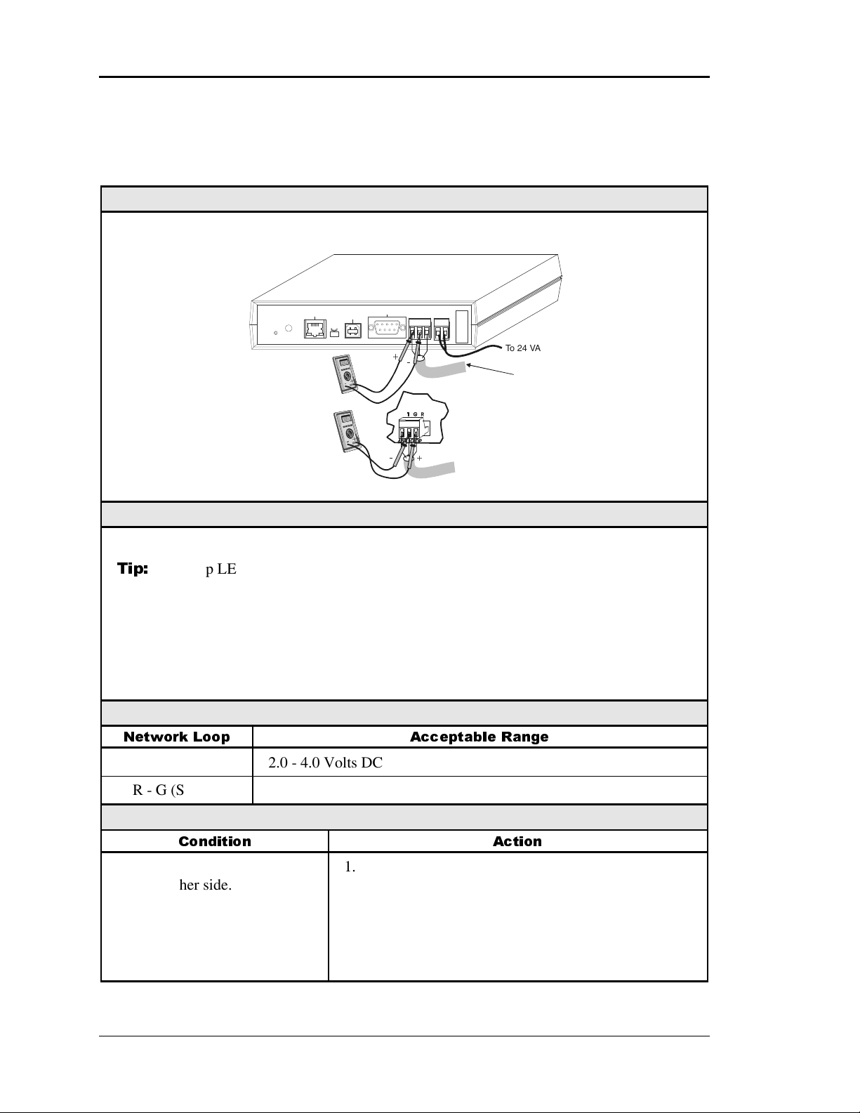
Section 4 Auto-Zone CV & CV-EX
Communications Loops
Checking CommLink Local Loop – CV
Diagram
CommLink IV
DIAG
T-To-G
+2.0 VDC
+4.0 VDC
Set Your Meter
To Read DC Volts
R-To-G
+2.0 VDC
+4.0 VDC
10/100
ETHERNET
ACT LNK
To
To
Config
USB
COMPUTER
USB
Normal
-
-
MODEM
RS-232
485 LOOP POWER
+
-
+
+
-
TGR
+
Serial #
24V
GND
To 2 4 VA C
Power Supply
To
Zone Manager
Network Loop
The CommLink IV Must Be
Powered Up For These Tests
Overview
This test checks for proper loop voltages at the CommLink IV.
Tip:
The Loop LED (located on the front panel) should “flicker” when the CommLink IV
is attempting to communicate. The Loop LED will flicker more noticeably for a few
seconds when first powered up. If the Loop LED does not flicker, the unit is defective.
Proper loop voltages are essential for reliable communications. It is normal to see fluctuations at this point on the CommLink IV. The average value should be close to the acceptable range described below. Values will vary upon initial powerup for about 10-15 sec-
onds as the unit attempts to communicate.
Measurements
Network Loop Acceptable Range
T - G (SHLD) 2.0 - 4.0 Volts DC
R - G (SHLD) 2.0 - 4.0 Volts DC
Action
Condition Action
If voltages are too high or too
low on either side.
1. Unplug the Comm loop from the CommLink IV and
Check for proper loop voltages. If a problem exists,
disconnect each CV Unit from the loop until the
problem is isolated.
2. Replace the CommLink IV. The driver chip is not
field-replaceable. See Page 4-22.
4-20 Start-Up and Troubleshooting
Page 99

Auto-Zone CV & CV-EX Section 4
Checking the CV Local Loop
Diagram
CommLink IV
T-To-G
+2.4 VDC
To
+3.3 VDC
R-To-G
+2.4 VDC
To
+3.3 VDC
10/100
ETHERNET
DIAG
ACT LNK
+
-
+
-
To Read DC Volts
+
-
-
MODEM
COMPUTER
RS-232
USB
Normal
Config
USB
Set Your Meter
+
Serial #
TGR
24V
GND
485 LOOP POWER
Communications
Loop
Disconnected
The CommLink IV Must Be
Powered Up For These Tests
Communications
Loop
Disconnected
To 24 VAC
Power Supply
The indicated values are typical of a normal system; actual readings may deviate slightly
due to the number of units connected and other system specific factors.
Note:
All of the connected CV Controllers should be powered up for this test.
Overview
This is a “quick check” to determine if any of the driver chips on the attached CV Controllers are damaged. Since all units will “float” both of their communications connections at
about 2.45 Volts, you can quickly check the entire communications loop by unplugging it at
the CommLink IV.
Note:
Tip:
Be sure that the loop you are testing does not have a short circuit from T to R.
The Loop LED (located on the front panel) should “flicker” when the CommLink IV
is attempting to communicate with the CV Controllers. There is a noticeable change in
the flicker when the loop is disconnected if you observe a normal functioning unit.
When the loop is reconnected, it may take up to 60 seconds before the CommLink IV
re-establishes communications with the CV Controllers.
Measurements
Network Loop Acceptable Range
T - G (SHLD) 2.4 - 3.3 Volts DC
R - G (SHLD) 2.4 - 3.3 Volts DC
Action
Condition Action
If voltages are too high or too
low on either side.
One or more of the CV Controllers has a damaged
Comm driver chip. Disconnect CV Controllers one at a
time to isolate the problem.
Start-Up and Troubleshooting 4-21
Page 100
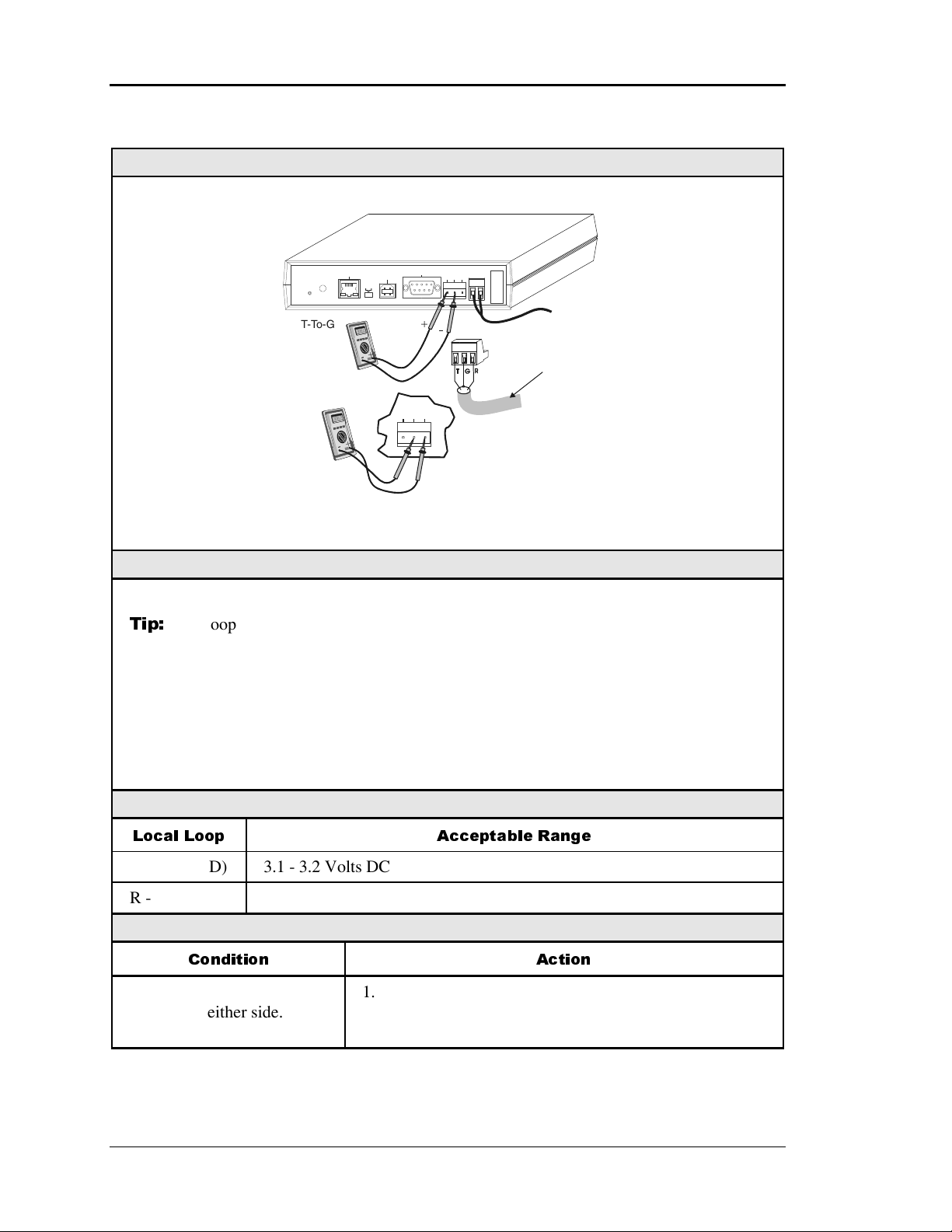
Section 4 Auto-Zone CV & CV-EX
Checking CommLink Driver – CV
Diagram
CommLink IV
+3.1 VDC
+3.2 VDC
R-To-G
+3.4 VDC
To
+3.6 VDC
DIAG
T-To-G
To
10/100
COMPUTER
ETHERNET
USB
Normal
Config
USB
ACT LNK
+
-
+
-
Set Your Meter
To Read DC Volts
MODEM
RS-232
485 LOOP
+
-
R
Serial #
TTGGR
GND
24V
485 LOOP
POWER
The CommLink IV Must Be
Powered Up For These Tests
To 24 VA C
Power Supply
Communications
Loop
Disconnected
Overview
This test checks for proper Communications Loop voltages coming from the CommLink IV.
Tip:
The Loop LED (located on the front panel) should “flicker” when the CommLink IV
is attempting to communicate. The Loop LED will flicker more noticeably for a
few seconds when first powered up. If the LED does not flicker, the unit is not
functioning.
Proper loop voltages are essential for reliable communications. It is normal to see fluctuations at this point on the CommLink IV. The average value should be close to the acceptable range described below. Values will vary upon initial powerup for about 10-15 sec-
onds as the unit attempts to communicate.
Measurements
Local Loop Acceptable Range
T - G (SHLD) 3.1 - 3.2 Volts DC
R - G (SHLD) 3.4 - 3.6 Volts DC
Action
Condition Action
If voltages are too high or
too low on either side.
1. The CommLink IV has a damaged comm driver chip.
Replace the CommLink IV. The driver chip is not
field-replaceable.
4-22 Start-Up and Troubleshooting
 Loading...