

Page 1

Design, Installation
Basic System
and Operations Manual
Revision 02C
Page 2

Page 3

Auto-Zone
Basic
Design, Installation & Operations Manual
Section 1..............................................................................System Overview
Section 2...................................................................Installation and Wiring
Section 3....................................................................................Programming
Section 4........................................................Start-Up and Troubleshooting
This document is subject to change without notice.
WattMaster Controls, Inc. assumes no responsibility
for errors, or omissions herein.
Auto-Zone Basic Installation & Operations Manual - Form WM-AZB-IO-02C
Auto-Zone is a registered trademark of WattMaster Controls, Inc.
Copyright 2009 WattMaster Controls, Inc.
All rights reserved.
Page 4

Page 5

Section 1
Table of Contents
Conventions .....................................................................1
General Information.........................................................3
Description of System Components.................................................................................3
Design Considerations.....................................................5
Zone Diversity .................................................................................................................5
Cooling - Partial Load Conditions ...................................................................................5
Heating - Partial Load Conditions ...................................................................................7
Override Conditions.........................................................................................................7
Building Pressurization....................................................................................................7
Design Guide....................................................................8
Step #1 - Zoning ..............................................................................................................8
Step #2 - Sizing the Central Unit ...................................................................................10
Step #3 - Duct Design Considerations...........................................................................10
Step #4 - Room Air Motion/Diffuser Selection.............................................................11
Step #5 - Bypass Damper Sizing ...................................................................................11
Step #6 - Sizing Zone Dampers .....................................................................................13
Round Dampers .............................................................................................................15
Rectangular Dampers.....................................................................................................15
Pressure Independent Zone Dampers ............................................................................16
Auxiliary Heat Control Options......................................17
Relay Expansion Board .................................................................................................18
Table of Figures & Tables
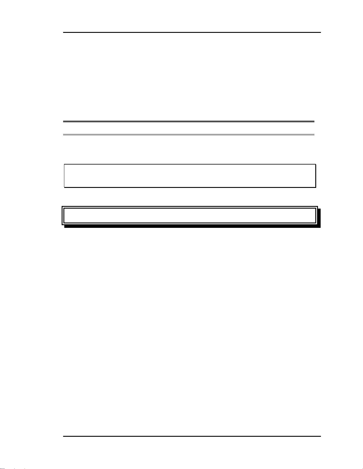
Figure 1-1: Auto-Zone Basic Control System...............................................................2
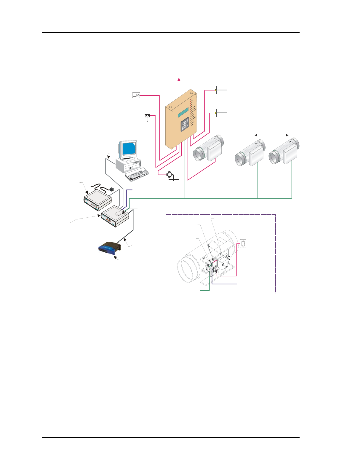
Figure 1-2: Control Zones Affected by the Outdoor Load ............................................9
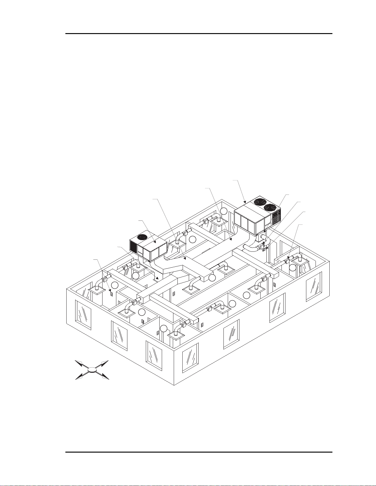
Figure 1-3: Locating the Static Pressure Sensor for Bypass Damper Control ............12
Figure 1-4: Round Damper Dimensions......................................................................14
Figure 1-5: Rectangular Damper & Kit Dimensions...................................................14
Table 1-1: Round Air Damper Selection .....................................................................15
Table 1-2: Rectangular Damper Selection...................................................................15
Table 1-3: Pressure Independent Flow Factors............................................................16
Design Guide
Page 6

Page 7
Auto-Zone Basic
Section 1
Conventions
This document uses the following definitions throughout as a guide to the user in
determining the nature of information presented:
Note: Additional information which may be helpful
Tip: Suggestion to make installation, set-up, and troubleshooting easier.
Caution: Items which may cause the equipment not to function correctly, but will
not otherwise damage components.
Warning: Errors which can result in damage to equipment and void warranties.
Design Guide 1-1
Page 8
Section 1
A
V
Auto-Zone Basic
To HVAC Unit
Control Panel
Supply
ir Temp
Sensor
Optional Remote Li nk II
Connects to CommLink IV
And Provides Alarm Call-Outs
A Second Remote Link Is Required
If Connection To Job Site
Is Desired From Remote Computer
Remote Link II
(Optional)
CommLink IV
The CommLink IV Is
Required For All Systems.
The IP Module, Remote
Link II, And Computer Are
Optional On All Systems.
All Computers Requ ire
Installation of Prism
Graphical User Interface
Software
USB Cable To Computer
Phone Cable To
Telephone
Wall Outlet Jack
CommLink IV
Single Loop
Economizer
(Actuator By Others)
Outside
Air Temp
Sensor
Computer
(Optional)
24VAC
Ethernet Cable To Router
Ethernet Router
(By Others)
When IP Module
Option Is Used
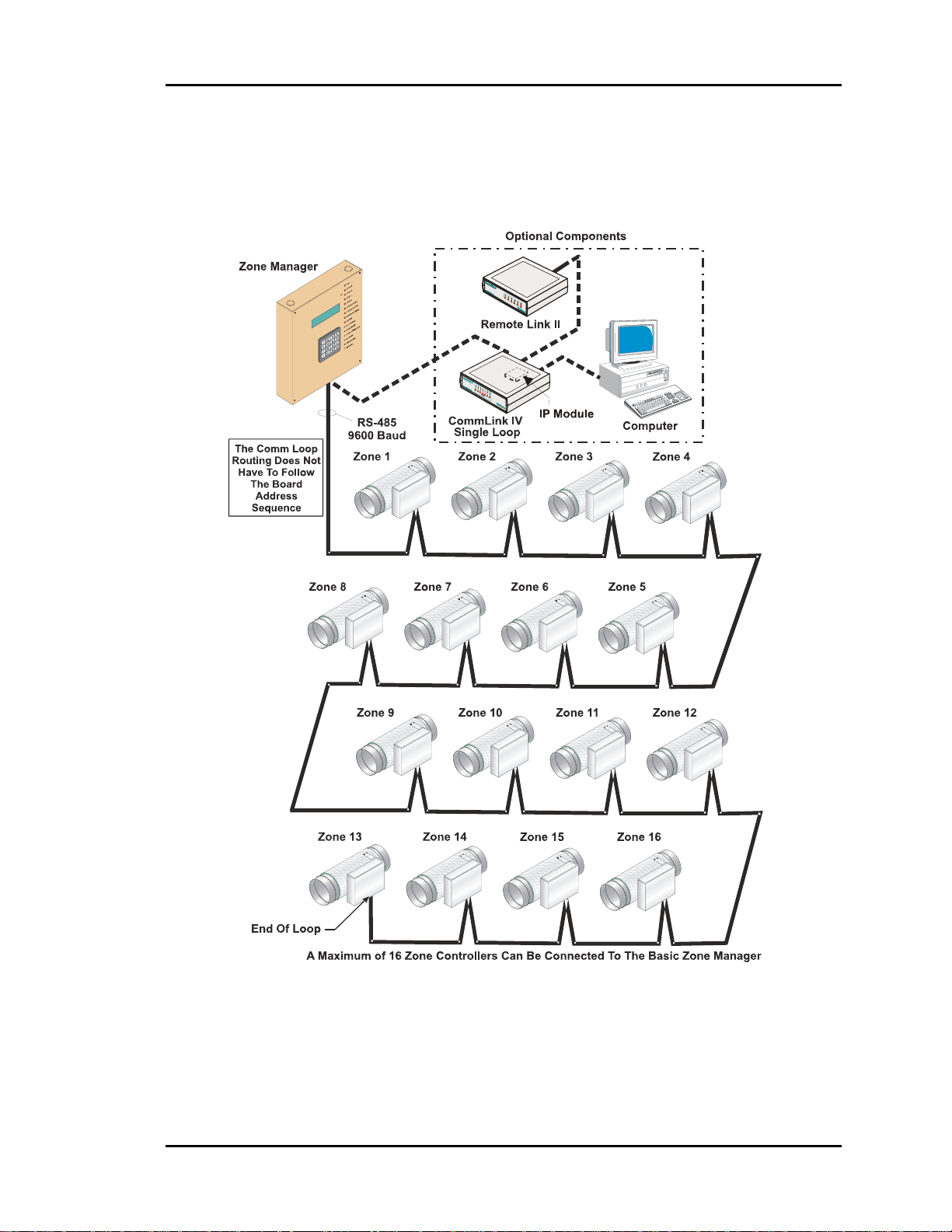
RS-485
9600 Baud
Optional IP Module
Installs Into CommLink IV
And Provides
LAN And Internet
Communications
With The Control System
Static
Pressure
Sensor
Zone Controller
elocity Sensor
(Optional)
Return
Air Temp
Sensor
Bypass Air
Damper
Typical Zone
Damper Actuator
Zone Air Dampers
Up to 16 Zone Air Dampers Allowed
#1
Room Sensor
with Optional
Override & Adj.
#16
RS-485
Comm Loop
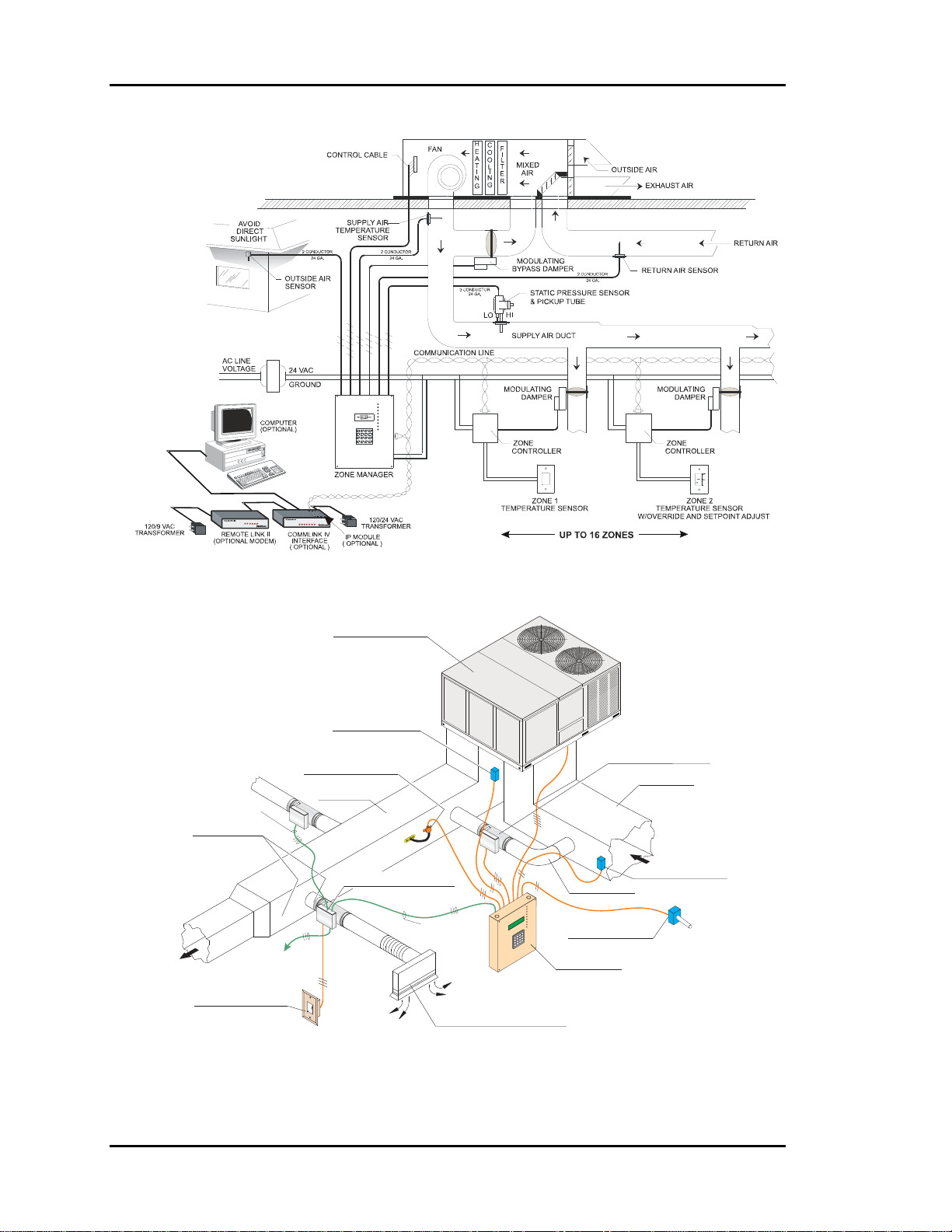
24 VAC
Figure 1-1: Auto-Zone Basic Control System
1-2 Design Guide
Page 9

Auto-Zone Basic
Section 1
General Information
The primary application of the Auto-Zone Basic Control System is to provide multiple
controlled comfort zones from a single zone, unitary heating and air-conditioning
package unit. It can also be applied to existing installations for improved comfort to
multiple zones currently controlled by a single thermostat.
Description of System Components
A typical Auto-Zone Basic Control System is comprised of the following four basic
components.
Zone Manager
The Zone Manager is a microprocessor-based controller which monitors up to 16 zones
in the system. The zone manager then controls the HVAC unit to satisfy the requirements
of each individual zone while maintaining efficient operation and comfort. The zone
manager is also responsible for controlling duct static pressure.
In the Auto-Zone Basic version, the Zone Manager has a display and a keypad. The 4line by 20-character display is backlighted, making it easier to read in low light
environments.
Bypass Damper
The bypass damper controls proper duct static pressure to insure proper airflow. The
damper is modulated by the Zone Manager based on a signal received from the static
pressure sensor connected to the main duct.
Zone Controller
The Zone Controller monitors space temperature and allocates proper airflow to the
assigned zone to achieve desired comfort and ventilation levels. If supply air temperature
will benefit the local zone temperature setpoint, the zone damper modulates to reduce or
increase airflow as needed. If supply air will not benefit the local zone, the controller will
direct the damper actuator to a minimum position and wait for a change in supply air
temperature.
Design Guide 1-3
Page 10

Section 1
Auto-Zone Basic
Zone Sensor
The patented zone sensor is a flush, wall-mounted design. A special plate on the face of
the sensor accurately senses space conditions. As a result of its unique design, the zone
sensor rejects the influence of internal wall temperature effects. The sensor comes in four
different configurations:
• Sensor only
• Sensor w/push-button override (override is fixed at 2 hours)
• Sensor w/setpoint adjustment
• Sensor w/override & setpoint adjustment
Any combination of these sensor configurations can be used with the system.
1-4 Design Guide
Page 11

Auto-Zone Basic
Section 1
Design Considerations
Consider the following items when designing a system using Auto-Zone.
Zone Diversity
The Auto-Zone Basic Control System is designed to improve tenant comfort by
dynamically re-balancing the air distribution when used with a typical constant volume
rooftop heating/cooling unit. If zones with extremely different load conditions are
serviced by a single rooftop unit, the result will be poor control and excessive wear due
to cycling of the equipment.
It is especially important to avoid mixing interior zones (which require cooling all year)
with exterior zones (which may require constant heat during winter months). If you must
mix zones under these conditions, consider using either VAV boxes with heat or separate
baseboard heat on exterior zones. Auto-Zone Basic Control Systems offer a variety of
methods to control additional zone heat to help you avoid problems.
Cooling - Partial Load Conditions
The engineer must be aware of several potential problems when applying the Auto-Zone
Basic Control System during cold weather operation.
Low Ambient Temperature Lockout
During very cold weather it is common for mechanical systems to have “low temp
lockouts” which protect equipment from damage if operated under these conditions.
Auto-Zone also provides user programmed lockouts for protection purposes, although
mechanical safeties should always be used as the final stage of protection.
If the rooftop unit services interior zones with thermal loads which require cooling when
outside temperatures are below the safe operating limits for your equipment, you should
seriously consider installing an economizer on your rooftop unit. The Auto-Zone control
system is designed to take advantage of an economizer if it is installed. The use of an
economizer will save money on utilities and provide comfort under conditions when it is
not possible to operate the mechanical cooling system.
Low Supply Air Temperatures
Under lightly loaded conditions much of the supply air may be bypassed back into the
return airside of the system. This bypassing will result in the lowering of the supply air
Design Guide 1-5
Page 12

Section 1
temperature, which may result in the supply air temperature reaching the low temp safety
limit. If the supply air low temp safety limit is exceeded, the control system will “cut-off”
the mechanical cooling to protect it from damage. Excessive cycling of the mechanical
system will result if this condition persists. Comfort may also suffer if the system cannot
run long enough to satisfy cooling demands.
A number of things can be done to reduce this problem. Some of these things depend
upon the type of installation.
• Avoid oversizing the unit. Do your load calculations carefully. Since Auto-Zone
directs the heating or cooling to the zones which require it, you may find that you can
use a smaller unit in many cases. Oversizing is the number one cause of excessive
low supply air temperature cycling.
• Increase your cooling minimum airflow or damper position settings to allow more air
during cooling operation. Be careful to avoid settings which are so high you cause
over cooling of the spaces. Find a compromise position.
• Bypass the air into the plenum instead of into the return air intake. Be careful if you
use this method since you may get “dumping” of cold air from your return air grilles.
This method works best with plenum returns. Do not use this method with ducted
returns unless you have carefully considered the consequences.
• Increase your static pressure setpoint to help reduce the amount of air being bypassed.
Be aware of increased noise levels and the cost of operation if you use excessive
static pressures.
Auto-Zone Basic
Warning: If the fan system has the capability of producing static pressures
which could damage ductwork, you must provide a manual reset high
pressure limit switch to cut-off the fan system in the event of high
duct static. Do not use your Auto-Zone Basic Control System as a
safety device!
• Use an Economizer. Although this is not a cure-all, it greatly improves operation
during cool weather when cooling loads are minimal. Using an Economizer also
improves ventilation and lowers operating costs, both of which are significant.
1-6 Design Guide
Page 13

Auto-Zone Basic
Section 1
Heating - Partial Load Conditions
Heating difficulties are less common than cooling difficulties. They are similar in nature,
however, and the cures are generally the same.
• Increase the Heating minimum setpoints on as many zones as possible.
• Increase the static pressure setting as high as is practical. Increasing static pressure
does not help if you are using pressure independent operation.
• Bypass to plenum instead of the return air intake if acceptable.
• Do not oversize your equipment.
• Use auxiliary heat in either your VAV boxes or baseboard.
Auto-Zone has a number of auxiliary heat control options which provide solutions to
most problems. Refer to the Auxiliary Heat Control Options topic near the end of this
section.
Override Conditions
After-hours overrides can produce aggravated partial load conditions in both the heating
and cooling modes. The problem is most commonly caused by a single zone being
overridden for after-hours use. This causes the rooftop equipment to operate for only one
zone. The Auto-Zone Basic Control System offers an improved solution to this common
problem by allowing a single override to trigger a group of zones via a “global” override.
This allows the system to operate with sufficient load to reduce cycling caused by light
load conditions.
Building Pressurization
If you are using an economizer, building pressurization must be addressed. Failure to
properly handle building pressurization may result in doors remaining open when the
economizer is operating. Pressurization problems can render economizer operation
useless. The following suggestions will help to avoid potential problems.
• Use powered exhaust when the system uses ducted returns. The return duct pressure
drop will cause most barometric relief dampers to function poorly or not at all. AutoZone has the ability to control a powered exhaust whenever the economizer is
operating.
• Use a separate building pressure control which operates a relief fan or dampers.
Design Guide 1-7
Page 14

Section 1
Auto-Zone Basic
Design Guide
There are six basic steps to designing an Auto-Zone Basic Control System:
1. Zoning
2. Sizing the Central Unit
3. Duct Design Considerations
4. Room Air Motion / Diffuser Selection
5. Bypass Damper Sizing
6. Sizing Zone Dampers
Step #1 - Zoning
Determine the number of zones. A single air handler unit can have no more than 16
zones. If the number of zones exceeds 16, then more than one Zone Manager will be
required. Consider using the Auto-Zone Plus system if more than one Zone Manager is
required.
The primary precaution to be taken in applying the Auto-Zone Basic Control System is to
select the zoning so that no zone will be at maximum (design) heating (or cooling) load
when any other zone requires the opposite temperature air to satisfy its load. For
example, depending on the wall, ceiling, floor material, and location within the building
(e.g. top or middle floor), a typical floor of a building usually has a minimum of 9
distinct temperature or control zones that are affected uniquely by the outdoor load.
These zones are depicted in Figure 1-2.
Depending on the size of the building and partition layout, some of these zones may
overlap or be insignificant from a zoning standpoint. For example, Zone 10 could be
multiple conference or computer rooms where additional zoning would be required, or it
could be as small as a corridor where no zoning is required. Similarly, zones 4 and 5
could have no external windows and no partitions between them and could be considered
a single zone. Zone 3 could be divided into multiple offices with full partitions between
them, thus requiring separate Zone Controllers because of different internal loads, but the
same external load.
Generally, the greater the number of individual Zone Controllers there are, the greater the
comfort. The designer will have to look at the specific building, balancing the costs of
multiple zones with the added comfort possible with multiple zones, to match the owner's
requirements.
1-8 Design Guide
Page 15
Auto-Zone Basic
Section 1
It is important to recognize that there are purely internal zones, such as Zone 10, which
may contain separate offices/conference/computer rooms. These internal zones could
easily have high cooling requirements while external zones (1, 2, 3, etc.) could be at or
near design heating load. This is a misapplication of the Auto-Zone Basic or Plus (or any
heating/cooling changeover) system. The interior zones with cooling-only loads should
be served with a separate air-conditioning unit (that could be zoned between multiple
rooms with a similar load profile). Supplemental heat could be added to the perimeter
zones and controlled with the auxiliary heat control board from the Zone Controller.
System performance will generally be compromised and frequent changeover from the
heating to the cooling mode will occur during the heating season if purely internal zones
are combined on the same air-conditioning unit serving perimeter zones.
Zoned HVAC Unit
Supply Air Duct
Supply Air Duct
9
Constant Volume HVAC Unit
Return Air Plenum
Bypass Damper
System Manager
Round Zone Damper
(Typical)
Room Sensor
(Typical)
W
S
Return Air Plenum
N
E
8
ER
G
ANA
M
rm
la
A
EM
n
tio
a
ic
n
s
mu
D
u
e
l
m
d
E
i
o
r
P
SYST
r
C
e
W
v
e
O
n
M
o
P
Z
8
-
D
3
o
:
t
E
3
I
u
S
0
P
A
M
7
U
9
R
C
/
A
1
C
L
0
/
O
A
1
0
.
O
C
N
I
N
c
S
s
L
E
O
R
T
N
O
u
C
n
R
e
E
T
M
S
A
M
T
T
A
W
3
2
6
1
r
e
t
n
E
5
r
9
a
e
l
4
C
s
8
u
n
i
M
7
0
.
c
e
D
*
1
7
6
W
A
R
W
A
R
M
N
O
E
R
M
R
A
L
C
O
V
O
R
O
L
E
R
M
N
O
E
R
M
R
A
L
C
O
V
O
R
O
L
E
R
10
W
A
R
M
N
O
E
R
M
R
A
L
C
O
V
O
R
O
L
E
R
2
3
5
W
A
R
M
N
O
E
R
M
R
A
L
C
O
V
O
R
O
L
E
R
4
W
A
R
M
N
O
E
R
M
R
A
L
C
O
V
O
R
O
L
E
R
W
A
R
M
N
O
E
R
M
R
A
L
C
O
V
O
R
O
L
E
R
Figure 1-2: Control Zones Affected by the Outdoor Load
Design Guide 1-9
Page 16

Section 1
Auto-Zone Basic
Step #2 - Sizing the Central Unit
Because the zones are controlled with variable air volume, it is unlikely that all zones
will be at design load at the same time. The zoning allows for the diversity of loads to be
taken into account and will often provide better comfort with a smaller HVAC unit.
In sizing the system, the individual zone loads should be calculated using any dependable
load estimating program. Because of diversity, the central unit should be selected for the
instantaneous peak load, not the sum of the peak loads, as would be done with a constant
volume single zone system. Consider the following when sizing the central unit.
• Size the peak cooling load based on the month and hour of the greatest total
building/system load.
• Heating should be sized for the lowest design temperature with an additional margin
for morning "pickup." This margin is generally recommended to be 20 to 25 percent
of base design.
Step #3 - Duct Design Considerations
The Auto-Zone Basic Control System uses a typical low pressure duct design. To reduce
noise problems, duct pressures should not exceed 1 inch W.C.
Primary trunk ducts should not be "undersized." This is especially true for "pressure
dependent" systems. Pressure dependent refers to the typical Auto-Zone Zone Controller
without the airflow sensor. With larger trunk ducts, it is easier to assure relatively constant
pressure to each zone. Runs should be as short as possible and the trunk duct system kept
as symmetrical as possible to facilitate system balancing. Wherever possible, run the trunk
ducts above corridors and locate the zone dampers above corridors to reduce the noise in
the space and facilitate service of the units. Trunk ducts should be sized for no more than
0.1 inch W.C. drop per 100 feet and a maximum duct velocity of 2000 FPM.
Note: For pressure independent terminal units with velocity sensors and
conventional "VAV" boxes properly selected for "quiet" operation, this 2000
FPM rule can be exceeded by up to 50 percent. The designer, however, should
be very experienced in VAV system design before considering modification
of this general rule.
Typical VAV systems with pressure independent terminals use the static regain method
for sizing ducts. The typical Auto-Zone Basic Control System is a low-pressure, pressure
dependent system that utilizes conventional unitary air-conditioning units. These systems
should use the equal-friction method of sizing the ducts and use the maximum loss of 0.1
inch per 100 feet as described above.
1-10 Design Guide
Page 17

Auto-Zone Basic
Section 1
Step #4 - Room Air Motion/Diffuser
Selection
Air motion is a consideration for occupant comfort. The selection of diffusers for an
Auto-Zone Basic Control System requires more care than a constant volume system due
to varying flow of air into the zones. Slot diffusers are recommended due to their superior
performance at low airflows. Because the zone airflow is variable volume, lower cost
round or rectangular diffusers that were satisfactory for constant volume may prove
unsatisfactory with an Auto-Zone Basic Control System. These diffusers may result in
"dumping" of the cold air at low flows in the cooling mode and insufficient room air
motion at low air flows in the heating mode. Although high air motion in the heating
mode can be undesirable, a slot diffuser with a high induction ratio generally helps to
reduce room air "stratification" when the heating comes from a ceiling diffuser. Linear
slot diffusers should be properly selected for the airflow and "throw" suited to the
specific installation or zone.
Additional factors to consider in diffuser selection are sound level and throw at design
flow. Generally, multiple diffusers will result in lower sound levels in the space, but this
must be balanced with the additional hardware and installation costs. It is commonly
recommended that slot diffusers be located near the perimeter or outside wall with the
airflow directed into the room. Consult your diffuser supplier or catalog for proper
diffuser sizing and location.
Series fan boxes may be used instead of zone dampers where higher induction rates are
desirable. If the heat loss on perimeter walls is high, such as large areas of glass, the use
of Series Fan Boxes may be indicated to maintain higher induction rates to offset
“downdrafts.” If the heat loss is greater than 275 BTUH/LINEAR FOOT, you should use
high quality slot diffusers next to the outer wall with the airflow directed inward to
counteract downdrafts during heating. Serious downdraft problems occur when heat
losses exceed 400 BTUH/LINEAR FOOT. In such case, both high induction diffusers
and series fan boxes are recommended.
Step #5 - Bypass Damper Sizing
Using a load calculation program, the bypass damper should be sized to give you the
maximum CFM of air to be bypassed, typically 60 to 70 percent of the HVAC units rated
capacity. Bypass Dampers can either be round or rectangular depending on building or
job requirements. Use the appropriate round or rectangular damper selection table to
determine the correct damper size for your application. To size the damper, select a
damper from the table based on calculated bypass CFM and a maximum velocity
between 1750-2250 FPM. When determining the bypass duct size, be sure to take into
account any transition fittings and associated pressure drops. (See Table 1-1: Round
Damper Selection or Table 1-2: Rectangular Damper Selection.)
Design Guide 1-11
Page 18
Section 1
Auto-Zone Basic
If space limitations or total airflow requires it, multiple bypass dampers can be controlled
in parallel. For proper control of the Bypass Damper, the static pressure sensor location is
very important. Refer to Figure 1-3: Locating the Static Pressure Sensor for Bypass
Damper Control below for proper mounting locations.
Preferred Location
If the trunk ducts are properly sized
for minimum pressure drop, the
Fan
location of the static pickup probe is
not particularly critical. It should
ideally be located at right angles to
the airflow in a straight section of the
supply duct approximately ⅔ the
distance of the total length of the
supply duct. Also, the probe should
SA Sensor
Bypass Damper
SPPickup
Supply Air Duct
RASensor
Return Air Duct
SP Sensor
be located not less than 3 duct
diameters downstream and 2 duct
diameters upstream of any elbow or
3D
Min.2DMin.
takeoff.
Less Than Ideal, But
Acceptable
Since the "ideal" location is often
Fan
difficult to find in an installation, a
location in the main trunk where
the tip is not in a "negative
pressure area" (e.g. just
downstream of the inside curve of
Supply Air Duct
SP Sensor
SA Sensor
SPPickup
Bypass Damper
RASensor
Return Air Duct
an elbow) or an area where the
tube opening is directly impacted
by the velocity of the supply air is
acceptable.
Least Desirable, But
Acceptable
If the supply duct comes directly
from the unit and immediately
splits in opposite directions, the
pressure pickup should be located
ahead of the split or as close to it
Supply Air Duct
TubingToBeEqual
LengthAnd Size
Fan
Bypass Damper
SA Sensor
RASensor
Return Air Duct
as possible, even if the bypass
damper(s) are located downstream
of the split.
SPPickups
SP Sensor
Figure 1-3: Locating the Static Pressure Sensor for Bypass Damper Control
1-12 Design Guide
Page 19

Auto-Zone Basic
Section 1
Step #6 – Sizing Zone Dampers
Use a load program to determine the peak load for each zone. These calculations will be
used in selecting the appropriate zone damper sizes.
A round damper or rectangular damper can be selected depending on the building or job
requirements. If the job requires pressure independent damper control, the damper
selected must be a round damper. Rectangular dampers are not available for pressure
independent control. Please see Table: 1-1 for round damper selection. Please see Table:
1-2 for rectangular damper selection.
Using the maximum acceptable velocity for a branch duct (typically 1000-1500 FPM for
minimal noise), find the smallest damper that will deliver the required CFM as
determined by the load program.
Go to either the Round Damper Selection table (Table: 1-1) or the Rectangular Damper
Selection table (Table: 1-2) depending on your requirements to select the dampers.
Locate the branch velocity used in the duct design program on the left hand column of
either damper sizing chart (Table: 1-1 or Table: 1-2). Move across the chart and find the
damper which will provide the acceptable CFM to meet each zone’s airflow
requirements.
Note: Compare the damper size selected against the duct size to determine if the
next size up or down will provide acceptable performance without requiring a
transition fitting.
Up to two additional dampers may be slaved together for larger zones. See zone wiring
diagram for details. This should be reserved for situations when it is not practical to use a
single large damper.
Design Guide 1-13
Page 20
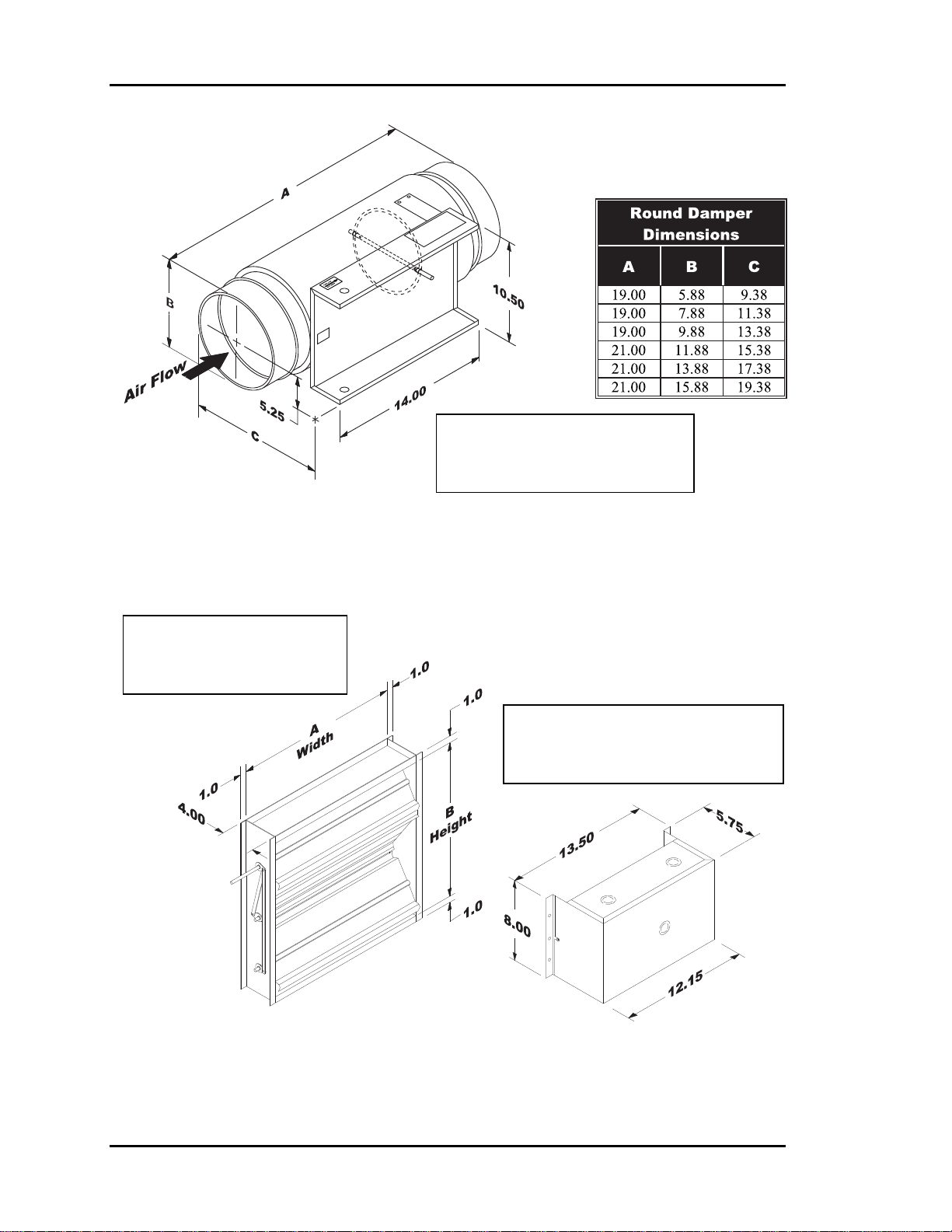
Section 1
Note: Dimensions Are
Identical For Round Zone,
Bypass & Slave Dampers
Auto-Zone Basic
Figure 1-4: Round Damper Dimensions
Note: See Table 1-2 for
Available “A” x “B”
Rectangular Damper Sizes
Note: Dimensions Are Identical
For Rectangular Zone, Bypass &
Slave Dampers
Figure 1-5: Rectangular Damper & Kit Dimensions
1-14 Design Guide
Page 21
Auto-Zone Basic
Section 1
Round Dampers
Round Air Damper Selection
Air Damper Round Duct Size
( Area Ft2 )
Velocity Through Round Air
Damper
(FPM)
750 - Zone
1000 - Zone
1250 - Zone
1500 - Zone
1750 - Bypass Only
2000 - Bypass Only
2250 - Bypass Only
Table 1-1: Round Air Damper Selection
6”
(0.188)
(0.338)
141 254 399 577 788 1031
188 338 532 769 1050 1375
235 423 665 961 1313 1718
282 507 798 1154 1575 2062
329 592 931 1346 1838 2405
376 676 1064 1538 2100 2749
423 761 1197 1730 2363 3094
8”
10”
(0.532)
12”
(0.769)
14”
(1.050)
Volume Through Round Air Damper
(CFM)
16”
(1.375)
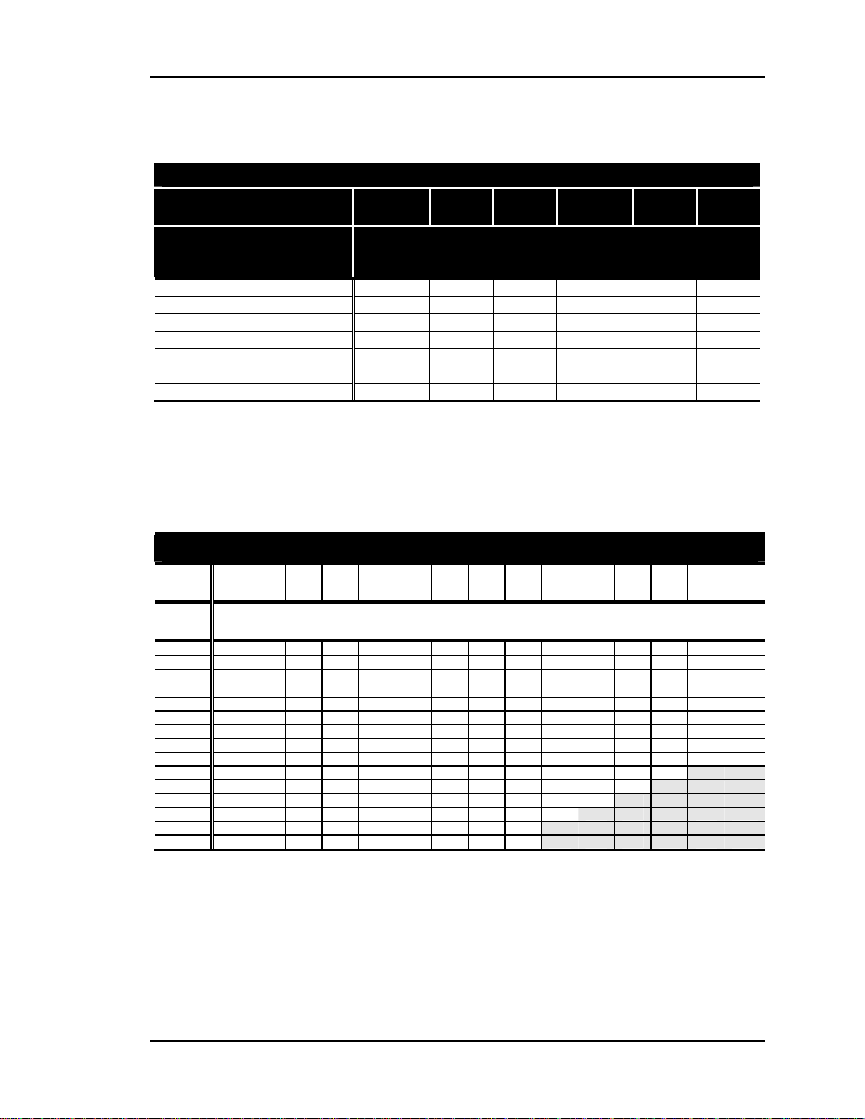
Rectangular Dampers
Rectangular Damper Selection
Damper
Height
(B)
Damper
Width
(A)
8”
10”
12”
14”
16”
18”
20”
22”
24”
26”
28”
30”
32”
34”
36”
Table 1-2: Rectangular Damper Selection
Notes: 1.) Zone Dampers Should Be Sized Based On The Required Zone CFM. The Table Above Is
8” 10” 12” 14” 16” 18” 20” 22” 24” 26” 28” 30” 32” 34” 36”
Airflow Through Rectangular Damper
CFM @ 1000 FPM Velocity
410 530 640 740 850 970 1080 1190 1300 1410 1520 1630 1740 1850 1970
510 590 690 800 910 1030 1150 1260 1380 1500 1610 1730 1840 2000 2080
560 650 730 850 970 1090 1210 1330 1460 1580 1700 1820 1940 2060 2190
660 770 880 1030 1180 1330 1480 1630 1760 1910 2060 2210 2360 2510 2640
750 890 1030 1200 1370 1540 1710 1880 2060 2230 2400 2570 2740 2910 3090
770 980 1180 1380 1580 1780 1980 2180 2350 2550 2750 2950 3150 3350 3540
850 1090 1330 1550 1770 1990 2210 2430 2650 2870 3090 3310 3530 3750 3990
930 1210 1480 1730 1980 2230 2480 2730 2950 3200 3450 3700 3950 4200 4440
950 1290 1630 1900 2170 2440 2710 2980 3250 3520 3790 4060 4330 4600 4880
990 1390 1780 2080 2380 2680 2980 3280 3550 3850 4150 4450 4750
1070 1500 1930 2250 2570 2890 3210 3530 3850 4170 4500 4820
1020 1550 2080 2430 2780 3130 3480 3830 4150 4500 4850
1090 1660 2230 2600 2970 3340 3710 4080 4450 4820
1150 1770 2380 2780 3180 3580 3980 4370 4750 NA NA NA NA NA NA
1060 1790 2520 2670 3090 3510 3930 4350 5040
NA NA NA NA NA
NA NA NA NA NA NA
NA NA NA
NA NA NA NA
Calculated Based On 1000 FPM Velocity Through The Rectangular Damper. Zone Damper
Recommended Velocity Is 1000 – 1500 FPM. Select 1000 FPM or Less for Quiet Operation. For Other
Velocities, Use The Following Multipliers To Obtain The Correct CFM: 500 FPM = 0.5, 750 FPM =
0.75, 1250 FPM = 1.25, 1500 FPM = 1.5, 2000 FPM = 2.0, 2250 FPM = 2.25.
2.) Bypass Dampers Should Be Selected for 60% to 70% of the HVAC Units Rated CFM Capacity.
Recommended Bypass Damper Velocity is 1750 – 2250 FPM.
NA NA
Design Guide 1-15
Page 22
Section 1
Auto-Zone Basic
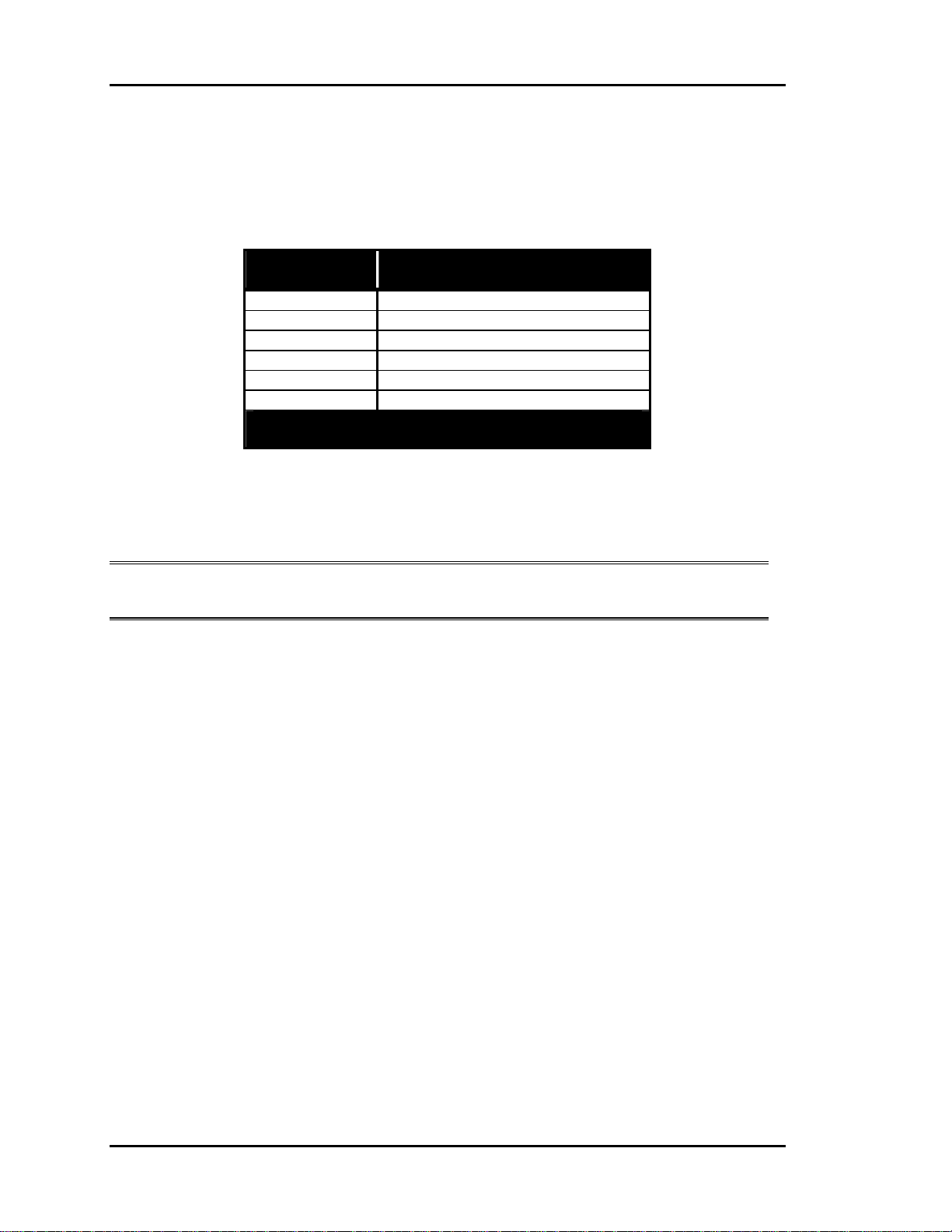
Pressure Independent Zone Dampers
Pressure Independent operation is only available for round zone dampers. Use the chart
below to set the calibration of the zone damper after installation.
Damper
Size
6” 474
8” 950
10” 1417
12” 2120
14” 2908
16” 3700
Flow Probe “K” Factor =
CFM @ 1” Velocity Pressure
Table 1-3: Pressure Independent Flow Factors
Flow Probe
“K” Factor
Note: K Factors are programmed for each zone so that the correct CFM will be
calculated for the different size air valves.
1-16 Design Guide
Page 23

Auto-Zone Basic
Section 1
Auxiliary Heat Control
Options
The Auto-Zone Basic Control System offers you a variety of methods to deal with zone
heating requirements. When deciding how to handle zone heating requirements, you
should consider the following:
• Does the rooftop unit have heat?
• Are you using fan-powered boxes?
• Is auxiliary heat used such as baseboard or radiant ceiling panels?
If the zone has some type of heat, you must consider how the heat is to be used. Typical
questions that should be asked:
Q: Should the zone heat be used as a first stage where it will become active before a
heating demand is created at the rooftop unit?
A: This mode is useful if you expect to have both heating and cooling demands at the
same time. The zone will use its own heat and allow the rooftop unit to continue to
provide cooling for other zones. This mode is also useful if the rooftop unit does not
have any heating capabilities.
Q: Is the zone heat only to be used as a second stage where it will be activated only if
the rooftop unit cannot maintain the space temperature such as during very cold
weather?
A: In this mode of operation the rooftop will examine the heating and cooling demands
and try to satisfy all of the zones by switching between heating and cooling as
required. The zone heat will only be activated if the zone temperature falls below a
selected limit.
Q: Should the zone heat be locked out if the rooftop unit is supplying warm air?
A: In many instances, it is desirable to use the rooftop heating whenever possible and
only use zone heat when the rooftop unit is in cooling or vent mode. This often
provides the most cost-effective operation since zone heat is typically electric. This
mode of operation will lockout zone heat if the rooftop is delivering heated air.
Design Guide 1-17
Page 24

Section 1
Auto-Zone Basic
Relay Expansion Board
The following describes the operation of each of the relays on the optional relay
expansion board. You can choose the appropriate relays for any given application.
Relay #1 - Parallel Fan
If the Zone is in cooling mode or vent mode, the parallel fan can activate any time the
zone temperature drops 0.5°F below the heating setpoint. It de-activates when the
temperature rises above the heating setpoint. The space temperature must be below the
AUX HEAT setpoint in the occupied mode before the Parallel Fan relay can be
energized.
Relay #2 - Box Heat
If the zone is in cooling mode or vent mode, the box heat can activate any time the zone
temperature drops 1.5°F below the heating setpoint. It de-activates when the temperature
rises to within 1.0°F of the heating setpoint. Box heat is not allowed to activate in the
heating mode when there is hot air being supplied by the air handling unit. This output
was intended to allow zone re-heat while the Zone Manager is satisfying cooling
demands in other zones. The space temperature must be below the AUX HEAT setpoint
in the occupied mode before the Box Heat relay can be energized.
Relay #3 - Aux Heat
In the occupied mode, the aux heat can activate any time the zone temperature is 0.5°F
below the aux heat setpoint. It de-activates when the temperature rises 0.5°F above the
aux heat setpoint. In the unoccupied mode, the aux heat uses the unoccupied heating
setpoint with the same deadband values mentioned above. This prevents the zone from
maintaining the same aux heat setpoint at night that it does during the daytime.
This output was intended to allow zone heating to augment the normal heating mode and
also to allow a zone an attempt to satisfy its own heating needs before creating a heating
demand at the Zone Manager.
Relay #4 - Series Fan
The series fan runs any time the main fan is running. This includes occupied and
unoccupied modes. The fan can only start running when the zone damper is closed, so it
determines that the damper is closed before starting the fan.
1-18 Design Guide
Page 25

Auto-Zone Basic
Index
Section 1
1 inch W.C. ......................................... 10
After-Hours
Overrides........................................... 7
Air
Bypassing.......................................... 6
Air Motion .......................................... 11
Auto-Zone Plus System ........................ 8
AUX HEAT
Setpoint ........................................... 18
Auxiliary Heat
Control Board ................................... 9
Control Options............................... 17
Recommendation .............................. 7
Barometric
Relief Dampers ................................. 7
Baseboard
Heat................................................. 17
Basic System
Design Guide .................................... 8
Diagram............................................. 2
Boards
Relay Expansion ............................. 18
Box Heat ............................................. 18
Building Pressurization......................... 7
Building Zones
Diagram............................................. 9
Bypass
Air ..................................................... 6
Plenum .............................................. 7
Return Air Intake .............................. 7
Bypass Damper
Overview........................................... 3
Sizing .......................................... 8, 11
Bypass Duct Size ................................ 11
Ceiling Diffuser .................................. 11
Central Unit
Sizing .......................................... 8, 10
CFM
Correct ............................................ 16
Maximum........................................ 11
Comfort............................................... 11
Cooling
Partial Load Conditions .................... 5
Cooling Load
Maximum.......................................... 8
Dampers
Slaved.............................................. 13
Design
Duct............................................. 8, 10
Room Air Motion.............................. 8
Zoning............................................... 8
Design Guide ........................................ 8
Diagrams
Basic System..................................... 2
Diffusers
Ceiling............................................. 11
High Induction ............................ 11
Selection...................................... 8, 11
Slot .................................................. 11
Dimensions
Rectangular Damper ....................... 14
Round Damper ................................ 14
Duct Design ........................................ 10
Considerations .................................. 8
Duct Static
High................................................... 6
Duct Static Pressure .............................. 3
Ducted Returns ..................................... 6
Ducts
Undersizing..................................... 10
Ductwork
Damaging.......................................... 6
Economizer
Benefits Of........................................ 6
Recommendation .............................. 5
Equipment
Oversizing......................................... 7
Exhaust
Powered............................................. 7
Exterior Zones....................................... 5
Global Override .................................... 7
Design Guide 1-19
Page 26

Section 1
Auto-Zone Basic
Heat
Auxiliary ........................................... 7
Baseboard........................................ 17
Supplemental..................................... 9
Heating
Auxiliary ......................................... 17
Difficulties ........................................ 7
Partial Load Conditions .................... 7
Radiant Ceiling Panels.................... 17
Heating Load
Maximum.......................................... 8
Heating Minimum Setpoints................. 7
High Induction Diffusers .................... 11
High Pressure Switch
Manual Reset .................................... 6
Induction Ratio
High................................................. 11
Interior Zones........................................ 5
K Factors............................................. 16
Linear Slot Diffusers........................... 11
Load .................................................... 10
Diversity.......................................... 10
Load Calculation
Program........................................... 11
Load Estimating
Program........................................... 10
Lockout
Low Temp......................................... 5
Low Ambient Termperature Lockout ... 5
Low Supply Air Temperatures.............. 5
Low Temp Lockout............................... 5
Manual Reset
High Pressure Switch........................ 6
Maximum
CFM ................................................ 11
Cooling Load .................................... 8
Duct Velocity.................................. 10
Heating Load..................................... 8
Mechanical Safeties .............................. 5
Mutliple Zones...................................... 8
Negative Pressure Area....................... 12
Noise Levels ......................................... 6
Noise Problems ................................... 10
Operation
Quiet................................................ 10
Override
After-Hours....................................... 7
Conditions......................................... 7
Global................................................ 7
Oversizing
Equipment......................................... 7
Unit ................................................... 6
Overview
Auto-Zone System ............................ 3
Bypass Damper ................................. 3
Zone Controller................................. 3
Zone Manager ................................... 3
Zone Sensor ...................................... 4
Parallel Fan ......................................... 18
Partial Load Conditions ........................ 5
Aggravated........................................ 7
Heating.............................................. 7
Plenum Returns..................................... 6
Powered Exhaust................................... 7
Pressure Dependent............................. 10
Pressure Independent
Flow Factors ................................... 16
Zone Dampers................................. 16
Pressurization
Building ............................................ 7
Problems
Noise ............................................... 10
Program
Load Calculation............................. 11
Load Estimating.............................. 10
Quiet Operation................................... 10
Radiant Ceiling Panels........................ 17
Rectangular Damper
Dimensions ..................................... 14
Selection.......................................... 15
Relay Expansion Board ...................... 18
Relief Dampers
Barometric......................................... 7
Returns
Ducted............................................... 6
Plenum .............................................. 6
Room Air Motion................................ 11
Design ............................................... 8
Round Air Damper
Dimensions ..................................... 14
1-20 Design Guide
Page 27

Auto-Zone Basic
Section 1
Selection.......................................... 15
Safeties.................................................. 5
Selection
Diffuser ....................................... 8, 11
Rectangular Damper ....................... 15
Room Air Motion............................ 11
Round Air Damper.......................... 15
Series Fan............................................ 18
Boxes............................................... 11
Setpoints
AUX HEAT .................................... 18
Heating Minimum............................. 7
Static Pressure................................... 6
Sizing
Bypass Damper ........................... 8, 11
Central Unit................................. 8, 10
Zone Dampers............................. 8, 13
Slaved
Dampers .......................................... 13
Slot Diffusers ...................................... 11
Linear .............................................. 11
Static Pickup Probe............................. 12
Static Pressure
Setpoint ............................................. 6
Setting ............................................... 7
Static Pressure Sensor........................... 3
Location .......................................... 12
Stratification........................................ 11
Supplemental
Heat................................................... 9
System
Design Guide .................................... 8
Overview........................................... 3
Performance ...................................... 9
Temperatures
Low Supply Air................................. 5
Temperature Lockout
Low Ambient .................................... 5
Undersizing
Ducts ............................................... 10
Units
Oversizing......................................... 6
Velocity
Maximum Acceptable..................... 13
Zone
Comfort............................................. 8
Design ............................................... 5
Diversity............................................ 5
Zone Controller
Overview........................................... 3
Zone Dampers
Pressure Independent ...................... 16
Sizing .......................................... 8, 13
Zone Heating
Auxiliary ......................................... 17
Zone Manager
Overview........................................... 3
Units Per ........................................... 8
Zone Sensor
Overview........................................... 4
Zones
Divided.............................................. 8
Exterior ............................................. 5
External............................................. 9
Interior .............................................. 5
Internal .............................................. 9
Multiple............................................. 8
Number Of ........................................ 8
Overlapping ...................................... 8
Perimeter........................................... 9
Zoning
Design ............................................... 8
Design Guide 1-21
Page 28

Section 1
Auto-Zone Basic
1-22 Design Guide
Page 29

Section 2
Table of Contents
Tips Before Beginning Installation..................................1
Zone Manager ..................................................................3
Communications Loop .....................................................8
Communications Loop Wiring Overview........................................................................9
Bypass Dampers ............................................................10
Zone Dampers................................................................13
Zone Controllers ............................................................14
Room Sensors ................................................................................................................21
Supply Air Temperature Sensor ....................................................................................23
Return Air Temperature Sensor.....................................................................................24
Outside Air Temperature Sensor ...................................................................................25
Duct Static Pressure Sensor ...........................................................................................26
Auxiliary Relay Board for Zone Controllers...................28
Zone Controller Auxiliary Relay Board Operation .......................................................29
CommLink IV Interface..................................................30
Basic System Worksheet................................................................................................33
Installation and Wiring
Page 30

Section 2
Table of Figures
Figure 2-1: System Overview........................................................................................2
Figure 2-2: Typical System Component Locations.......................................................2
Figure 2-3: Zone Manager Dimensions ........................................................................3
Figure 2-4: Zone Manager Component Locations.........................................................4
Figure 2-5: Zone Manager Wiring.................................................................................5
Figure 2-6: Zone Manager Address Switch Setting ......................................................7
Figure 2-7: Communication Loop Wiring, Daisy-Chain Configuration .......................9
Figure 2-8: Round and Rectangular Bypass Dampers.................................................10
Figure 2-9: Bypass Damper Wiring.............................................................................12
Figure 2-10: Round and Rectangular Zone Dampers .................................................13
Figure 2-11: Zone Controller Components.................................................................15
Figure 2-12: Zone Controller Wiring..........................................................................17
Figure 2-13: Zone Controller Address Switch Settings..............................................19
Figure 2-14: Slaved Zone Controller Wiring..............................................................20
Figure 2-15: Room Sensor Installation .......................................................................21
Figure 2-16: Room Sensor Wiring..............................................................................22
Figure 2-17: Supply or Return Air Sensor Dimensions and Installation ....................23
Figure 2-18: Outside Air Temperature Sensor Dimensions and Installation..............25
Figure 2-19: Duct Static Pressure Sensor Dimensions and Installation .....................26
Figure 2-20: Static Pressure Sensor Wiring................................................................27
Figure 2-21: Auxiliary Relay Board Layout...............................................................28
Figure 2-22: CommLink IV Interface Communication Wiring..................................30
Figure 2-23: CommLink IV Interface Connections....................................................31
Figure 2-24: CommLink IVJumper Switch Settings ..................................................32
Installation and Wiring
Page 31

Auto-Zone Basic
Section 2
Tips Before Beginning
Installation
Take a few moments to review the following before beginning installation of the
Auto-Zone Basic Control System.
• Familiarize yourself with all system components and review all documentation.
Pay special attention to “Cautions” and “Warnings” since these may keep you
from experiencing unnecessary problems.
Before installing zone dampers, be sure to tag each damper with its appropriate location.
It is also best to set the zone controller address switches before mounting in drop ceilings.
Use the Basic System Worksheet found in the back of this section or in the Basic Submittal Package to list all zone locations and Zone Manager configurations. This will assist
you greatly when setting up the system.
• Be sure to install all wiring according to local, state, and national codes.
• Pay close attention to communication wiring since the most common mistakes are
made in this area. Polarity is the most important rule. Make notes on your wiring diagrams as to which color wire you will be using on each terminal.
• When in doubt - ask! Contact your local Auto-Zone distributor if you have any ques-
tions. The only dumb questions are the ones you don’t ask.
• Remember - each electronic device contains only one puff of smoke. If you release it,
you have voided the warranty! So please be careful and pay attention.
Installation and Wiring
2-1
Page 32
Section 2
Auto-Zone Basic
Figure 2-1: System Overview
Typical HVAC Unit
(Packaged or Split System)
Supply Temp Sensor
(Ahead of Bypass Takeoff)
Static Pressure Pickup
(2/3 Of The Way Down Main Duct)
LOCAL COMM LOOP
TWISTED PAIR
WITH SHIELD TO
ZONE CONTROLLER
Above Corridor
( Preferred Location )
Supply Duct
Zone Damper and Control
LOCAL COMM LOOP
TWISTED PAIR WITH
SHIELD TO OTHER
ZONE CONTROLLERS
Zone Sensor
(4-1/2' to 5'; Shoulder Height)
W
A
R
M
N
O
E
R
M
R
A
L
C
O
O
V
R
O
L
E
R
( Over Corridor for Easy Service )
LOCAL COMM LOOP
TWISTED PAIR
WITH SHIELD TO
ZONE CONTROLLER
+
N
FA
1
L
O
O
C
2
L
O
O
C
®
1
T
A
E
H
2
T
A
N
E
E
H
P
O
S
S
E
A
P
S
Y
O
B
L
C
S
N
S
A
IO
P
T
Y
A
B
C
I
+
N
U
M
M
O
C
M
R
A
L
S
A
E
N
O
Z
L
L
E
A
N
=
O
R
Z
A
A
H
E
L
C
A
/C
E
T
I
=
N
B
U
C
A
V
H
=
S
A
C
M
R
A
L
3
R
A
E
T
=
B
N
D
E
2
/
P
E
6
T
S
1
=
L
C
A
#
5
M
I
C
9
E
D
4
=
D
*
8
#
7
0
*
+
+
Diffuser at Perimeter Wall
(Direct Airflow Inward Towards Center of Area)
Bypass Damper
( Locate Where Easily Accessible )
Return Temp Sensor
Duct to Return
(Preferred)
Outdoor Air Sensor
(Mount Away From Direct Sunlight))
(Avoid Mixed Air Area)
Zone Manager
Return Duct
Figure 2-2: Typical System Component Locations
2-2
Installation and Wiring
Page 33

Auto-Zone Basic
Section 2
Zone Manager
The Zone Manager may be installed in any convenient, protected location. Observe the
recommended environmental limitations for the Zone Manager (see Technical Data section of product data sheet) when choosing a location. The unit should be mounted with
the display at eye level for easy viewing.
When installing the Zone Manager with display and keypad, you must remove the cover.
Use care not to damage the display while handling and protect the display from physical
damage while removed.
The ribbon cable should be unplugged from the display board which is mounted inside
the front cover. The ribbon cable is keyed to prevent a reverse connection.
Warning: Always remove power before connecting or disconnecting the ribbon
cable which joins the display and keypad to the Zone Manager. Failure to observe this precaution may result in damage to the display or
Zone Manager.
The Zone Manager may be mounted without removing the controller from the enclosure
or mounting plate. The unit is mounted by four (4) screws in the corners. Select the correct screws or other fasteners for the type of mounting material being utilized.
Please see Figure 2-3, Figure 2-4, Figure 2-5, and Figure 2-6 for Zone Manager dimen-
sions, components, wiring, and addressing information.
3.00
Display
11.50
9.25
FRI
Mode
03:48PM
+
08-08-01
Cool
OCCUPIED
ALARMS
NO
1
4
7
*
A
3
B
2
6
C
5
9
D
8
#
0
+
N
FA
1
L
O
O
C
2
L
O
O
C
1
T
EA
H
2
T
EA
H
PEN
O
S
AS
SE
YP
B
LO
C
N
SS
A
TIO
YP
A
B
IC
N
U
M
M
O
C
RM
LA
S
A
NE
ZO
LL
E
A
N
=
ZO
A
AR
H
C
EA
=
B
UNIT/CLE
C
A
V
H
=
S
C
M
R
ALA
TER
=
D
/EN
STEP
=
L
A
#
IM
EC
D
=
*
+
Keypad
+
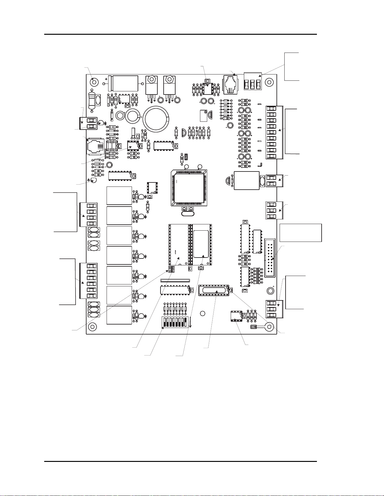
Figure 2-3: Zone Manager Dimensions
Installation and Wiring
2-3
Page 34
Section 2
Auto-Zone Basic
Mounting Holes
Typ. Of 4
24 VAC
Power Input
Power LED
Not Used
Real Time
Clock Chip
Comm
LED
Bypass
Damper
Connections
FDBK
GND
Open
Close
HVAC Unit
Connections
(R) Common
Fan
Cool 1
Cool 2
Heat 1
Heat 2
RAM Size
Select
Jumper
24VAC
GND
I2CEXP PORT
D13
D14
D15
R39
R40
BYPASSPDAMPER
TB7
R10
C1
D1
V1
U2
C6
R7
D7
POWER
TB2
REC
FDBK
GND
OPEN
CLOSE
V3
V4
V5
V6
R
FAN
COOL1
COOL2
HEAT1
HEAT2
V7
V8
V9
L1
R18
D9
D11
R26
CX3
U3
R32
R34
C17
U6
K2
K4K3
K5
K7K6
K8
RAM
Chip
Address Switch
(Set To 0 Without
CommLink. Set to 17
With CommLink)
Static Pressure
Real Time
Clock Chip
R2
R1
VR1
R9
C9
D12
Y1
R25
C12
SC1
CX4
R29
R33
R35
CX6
U7
OPEN
CX7
D17
R41
R42
CLOSE
D18
R43
FAN
R44
D19
COOL1
R46
D20
COOL2
D21
R52
HEAT1
D22
R56
HEAT2
D31
R57
VR2
C2
C3
5.11V
ADJUST
Q1
R20
D10
R22
R21
CX5
J01
U5
EWDOG
R36
C18
U8
C21 C20
32K
8K
JO2
U13
D23
D24
D26
D25
D27
SW1
NET
B
32
16
X2
RAM
U10
CX10
RN2
1
CX13
D29
D30
D28
MADE IN U.S.A.
ADD
284
1
PAL
EPROM
Chip
Chip
Sensor - Optional
Modular Connection
Input
CX1
R5
R4
R3
U1
D2
D3
C4 C5
D4
D5
D6
D8
R15
VR3
R13
R23
R24
R61
C19
5.11V
ADJ
YS101722
Rev. 2
EPROM
U11
CX11
1992
SENSOR JACK
PRESSURE
PJ1
R11
R12
C7
R14
R16
R17
C11
R19
C13
R27
R28
R30
R31
C15
R37
R38
Q2
D16
CX9
U9
R45
R47
R48
U12
U14
CX14
CX12
CX15
U15
RS-485
COMM DRIVER
+5V
PU1
C8
PU2
PU3
C14
PU4
PU5
ECONOMIZER
R58
R59
SIG
C16
PU6
EXH/RELIEF
RN1
R49
R55
R60
TB1
GND
ANALOG
INPUTS
+12V
SAT
RAT
OAT
AUX1
AUX2
AUX3
GND
GND
V2
ANALOG
OUTPUTS
GND
C22
T
SH
R
RS-485
Communications
Driver Chip
TB3
EXHAUST
CONTACTS
N.O.
TB4
TB5
Note:
EXP
Keypad & Display
BUSS
Not Shown
P1
COMM
TB8
Static Pressure
Sensor Inputs
+5V
SIG
GND
Analog Inputs
SAT
RAT
OAT
AUX1
AUX2
AUX3
GND
Binary Output
Relief/Exhaust
Fans
Analog Output
0-10 VDC
Economizer
Display &
Keypad
Ribbon Cable
Connector
RS-485
Communications
Loop Connection
T
SH
R
Typical
Pin 1
Indicator
Figure 2-4: Zone Manager Component Locations
2-4
Installation and Wiring
Page 35

Auto-Zone Basic
Section 2
Bypass
Air Damper
Actuator
Bypass & Slave
Interface Card
BYPASSAND
SLAVEINTERFACE
YS101824
OPEN
CLOSE
FROM ZONE
LD2
LD1
W1
HVAC Unit
W2
24VAC Only
Line
Voltage
TO ACTUATOR
PJ1
TB2
CONTROLLER
PJ2
TB1
R
G
Y1
Y2
GND
OPEN
CLOSE
FDBK
GND
OPEN
CLOSE
24VAC
GND
See Note 1 &2
Splice As
Required
10
Basic Zone Manager
+
NE5090
BYPASS
OPEN
BYPASS
CLOSE
G
FAN
Y1
COOL 1
Y2
COOL 2
W1
HEAT 1
W2
HEAT 2
+
LCD DISPLAY
KEYPAD
1 2 3BA
4 5 6
0*#D
D
D
D
D
D
D
D
24
22
20
18
19
23
21
SW
1
16
B
4
2
NET
32
8
Communications To Zone
Notes:
1.)24 VAC Must Be Connected So
That All Ground Wires Remain
Common.
2.)All Wiring To Be In Accordance With
Local And National Electrical Codes
and Specifications.
3.)All Communication Wiring To Be 18
Ga. Minimum, 2 Conductor Twisted
Pair With Shield. Belden #82760 Or
Equivalent.
24VAC
GND
+
POWER
TB2
+
REC
FDBK
GND
OPEN
CLOSE
FAN
COOL1
COOL2
HEAT1
HEAT2
V3
V4
V5
V6
LO HI
+
5.11V
ADJUST
&
D
17
MADE IN U.S.A.
C 1992
RockerDown
>
ADD
OFF
1
RS-485
Controllers
Static
Pressure
Sensor
C987
Pick-up
SEN
SO
R
JA
C
K
PJ1
75176
RS-485
COMM DRIVER
Static
PRESSURE
+5V
+
Red
Blk
SIG
RIBBON
CABLE
Grn
TB12
GND
ANALOG
INPUTS
+12V
+
SAT
RAT
OAT
AUX1
+
AUX2
AUX3
GND
GND
+
EXHAUST
CONTACTS
N.O.
ANALOG
OUTPUTS
A1
A2
G
EXP
BUSS
R5
R6
C
2
COMM
T
SH
R
Local Loop
TB2
P1
C
1
+
To Relief / Exhaust Fans
RS-485
Communications
To CommLink
When Used
Suppy Air Temp.
Sensor
Return Air Temp.
Sensor
Outdoor Air Temp.
Auxiliary Inputs
( Dry Contacts )
Aux3
Aux2
Forced
Filter
Occupied
Alarm
Mode
Economizer Actuator
Use Extreme Care When Wiring
Economizer Actuators
Never Connect Or Disconnect
Wiring With Power Applied!
Never Apply Power If The
Gnd ( 1 Com ) Terminal On The
Actuator Is Not Connected.
Belimo Actuator Wiring Shown.
Consult Factory For Other
Models Of Economizer Actuators.
Some Actuators Require Isolation
Transformers In Order To Prevent
Damage To The Controller Board.
Sensor
(See Note 4)
Aux1
Economizer
Disable
5U
BELIMO
4Y2
AF24-SR
3Y1
133 IN-LB
2+
1 COM
WARNING!
Figure 2-5: Zone Manager Wiring
Warning: Use extreme care not to damage any of the electronic components
while mounting the enclosure. Mark the holes and then remove the
Zone Manager before drilling. Do not allow metal shavings
to fall onto the circuit boards.
Installation and Wiring
2-5
Page 36

Section 2
The Zone Manager requires the following electrical connections:
18-Gauge minimum unless otherwise noted.
-24VAC Supply Voltage........................................................................... 2 Conductors
-Communications Loop ...................................... 2 Conductor twisted pair with shield
(Belden #82760 or equivalent)
-Supply Air Temperature Sensor........................................ (24 ga. Min.) 2 Conductors
-Return Air Temperature Sensor ........................................(24 ga. Min.) 2 Conductors
-Outside Air Temperature Sensor.......................................(24 ga. Min.) 2 Conductors
-Supply Static Pressure Sensor ...........................................(24 ga. Min.) 3 Conductors
-Bypass Damper........................................................................................ 4 Conductors
-HVAC Unit Control Wiring.....................................................................R - Common
G - Fan
Y1 - Cool 1
Y2 - Cool 2
W1 - Heat 1
W2 - Heat 2
Tip: After making all electrical connections, you should unplug all terminal blocks
on the Zone Manager until you are ready to begin the checkout procedure. This
may help to prevent damage if wiring errors occur elsewhere in the system during installation or start-up.
Auto-Zone Basic
2-6
Installation and Wiring
Page 37

Auto-Zone Basic
BYPASSPDAMPER
FDBK
GND
OPEN
CLOSE
V3
K4K3
V4
V5
V6
K5
TB7
R
FAN
COOL1
COOL2
HEAT1
K7K6
HEAT2
V7
V8
K8
V9
CLOSE
D18
R43
R44
D19
COOL1
R46
D20
COOL2
D21
R52
HEAT1
D22
R56
HEAT2
R57
D31
Section 2
RAM
EPROM
FAN
U10
32K
8K
JO2
RN2
U13
D23
D24
D26
D25
D29
D28
D27
SW1
NET
32
B
16
U11
CX10
CX11
1
CX13
D30
MADEIN U.S.A.
1992
ADD
284
1
U14
U9
R45
R47
R48
U12
CX14
U15
RS-485
COMMDRIVER
CX9
RN1
R49
P1
R55
C22
CX12
CX15
COMM
T
R58
R59
R60
SH
R
TB8
RS-485
Communications
To CommLink
When Used
Local Loop
RS-485
9600 Baud
RS-485
Communications To Zone
Controllers
All Comm Loop Wiring Is
Straight Thru
T
T
SH
R
T
SH
SH
R
R
T
SH
R
These Switches Must Be
In The OFF Position
As Shown
RockerDown
>
Notes:
1.)AllCommunication Wiring To Be
2 Conductor Twisted Pair With
Shield. Use Belden #82760 Or
Equivalent.
2.)It Is Recommended That All
Controllers Address Switches Are
Set Before Installation.
3.)Power To The Zone Manager Must Be
Cycled Before Address Switch
Changes Will Take Affect.
3232BBNET
16
4
8
Address Switch Must Be Set
To Address 0 on Zone Manager Board
As Shown
Basic System Without CommLink
NET
16
4
8
Address Switch Must Be Set
To Address 17 on Zone Manager
Board When CommLink Is Used
ADD
OFF
1
2
These Switches Must Be
In The OFF Position
As Shown
RockerDown
>
ADD
OFF
1
2
Basic System With CommLink
Figure 2-6: Zone Manager Address Switch Setting
NET
NET
B
B
Zone Manager
Address Switch
ADD
2
4
8
16
32
Zone Manager
Address Switch
ADD
2
4
8
16
32
1
1
Caution: Your Auto-Zone Basic Control System will not work properly unless
you set the Address switch correctly. Remember, you must power
down the Zone Manager after changing the address switch in order for
the change to take effect.
Installation and Wiring
2-7
Page 38

Section 2
Auto-Zone Basic
Communications Loop
The communications network is a two-wire shielded RS-485 loop. The loop is best con-
nected in a daisy chain configuration, meaning the loop is connected from one controller
to another. It is not necessary to sequentially address the zone controllers in relation to
their location on the loop. Cable must be Belden No. 82760 or equivalent.
Tip: Incorrect wiring of the communications loop is the most common mistake made
during installation. Before beginning installation, write down the wire color
used on each terminal connection and consistently maintain that color code. It is
recommended that a continuous wire run be made between devices. Any time a
splice is made in the cable, you increase your chance of problems.
Caution: Make sure when you are inserting wires into the terminal blocks that
strands of wire do not stick out and touch the next terminal. This could
cause a short or erratic operation.
Note: The loop does not have to follow the controller address sequence.
Caution: If comm loop is not installed in conduit, be careful to position the cable
away from high noise devices like fluorescent lights, transformers,
VFDs, etc. Conduit is not required for comm loop wiring unless required by local codes.
2-8
Installation and Wiring
Page 39
Auto-Zone Basic
Section 2
Communications Loop Wiring Overview
The daisy chain is the best method for running a communications loop since there is only
one starting point and one ending point. See Figure 2-7.
Figure 2-7: Communication Loop Wiring, Daisy-Chain Configuration
Even though the daisy chain configuration is preferred, the star configuration can also be
used. If required, a combination of the two can also be used. Remember, the best comm
loop wiring is the one which utilizes the minimum number of ends while using the shortest wiring path. See Figure 2-6 and Figure 2-13 for controller addressing information.
Installation and Wiring
2-9
Page 40

Section 2
Auto-Zone Basic
Bypass Dampers
The Bypass Damper can be either round or rectangular. The Round Bypass Damper is
supplied with the Damper Actuator and Bypass Wiring Interface Board factory mounted
in a sheet metal enclosure attached to a Round Air Damper assembly. This Round Bypass
Damper Package is field connected to the appropriate size round duct. Rectangular Bypass Dampers mount directly in the rectangular ductwork using flanged connections field
formed in the rectangular ductwork. A Rectangular Bypass Damper Kit is required to
complete the Rectangular Bypass Damper package. The Rectangular Bypass Damper Kit
is supplied with the Damper Actuator and Bypass Wiring Interface Board factory
mounted in a sheet metal enclosure. This assembly is then field mounted over the Rectangular Damper shaft and secured to the ductwork with sheet metal screws.
Figure 2-8: Round and Rectangular Bypass Dampers
Up to two additional Rectangular Bypass or Round Bypass Dampers can be slaved together when it is not practical to use a single large damper. See Figure 2-9. The bypass
damper(s) should be installed as close as possible to the rooftop unit.
Round and Rectangular Bypass Dampers should be securely hung using either wire cradles or metal strapping. While the dampers may be hung in any position, avoid sharp
kinks in flexible duct to prevent airflow restrictions. The Round Bypass Dampers are in-
sulated for use in non-conditioned spaces to avoid sweating and to improve energy effi-
ciency.
See Figure 2-2 for a typical bypass damper mounting location. See Figure 2-9 for typical
Bypass Wiring Interface Board wiring instructions.
2-10
Installation and Wiring
Page 41
Auto-Zone Basic
Section 2
Warning: If sheet metal screws are used to mount the dampers, be certain that
they do not interfere with the movement of the damper blade.
Warning: Never depress the actuator clutch with power applied. Unplug the ac-
tuator cable before depressing the clutch and attempting to rotate the
damper blade. Do not force the damper blade as this can damage the
gears in the damper actuator.
Installation and Wiring
2-11
Page 42

Section 2
Auto-Zone Basic
BYPASS ACTUATOR #1
(MASTER)
10
MODULAR CABLE
BYPASS ACTUATOR #3 (SLAVE)
(WHEN USED)
1 10 0
NOT USED FOR
THIS APPLICATION
CLOSE
OPEN
TB1
GND
FDBK
CLOSE
OPEN
GND
BYPASS &
SLAVE INTERFACE CARD
PJ2
FROM ZONE
CONTROLLER
TB2
PJ1
TO ACTUATOR
LD2
OPEN
SLAVEINTERFACE
YS101824
LD1
CLOSE
BYPASSAND
BYPASS ACTUATOR #2 (SLAVE)
ZONE MANAGER BOARD
NE5090
REC
K1
OPEN
FDBK
GND
K2
CLOSE
OPEN
CLOSE
V3
V4
NETWORK
T
SH
R
BYPASS &
SLAVE INTERFACE CARD
TO ACTUATOR
BYPASSAND
SLAVEINTERFACE
YS101824
PJ1
GND
OPEN
TB2
CLOSE
OPEN
CLOSE
FROM ZONE
CONTROLLER
PJ2
LD2
LD1
FDBK
TB1
CLOSE
GND
OPEN
MODULAR
CABLE
NOT USED FOR
THIS APPLICATION
BYPASS &
SLAVE INTERFACE CARD
TO ACTUATOR
BYPASSAND
SLAVEINTERFACE
YS101824
PJ1
GND
OPEN
TB2
CLOSE
OPEN
CLOSE
FROM ZONE
CONTROLLER
PJ2
LD2
LD1
FDBK
GND
TB1
OPEN
CLOSE
MODULAR
CABLE
NOT USED FOR
THIS APPLICATION
Figure 2-9: Bypass Damper Wiring
Warning: If the fan system has the capability of producing static pressures
which could damage ductwork, you must provide a manual reset
high pressure limit switch to cut-off the fan system in the event of
high duct static. Do not use your Auto-Zone Basic Con-
trol System as a safety device!
2-12
Installation and Wiring
Page 43
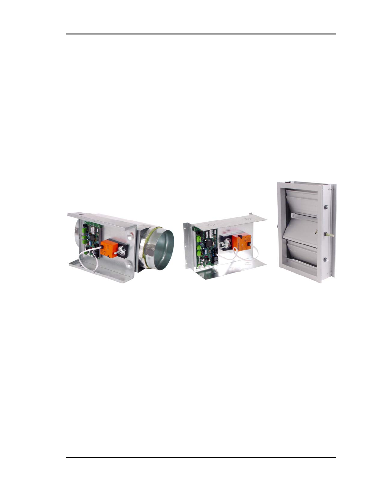
Auto-Zone Basic
Section 2
Zone Dampers
The Zone Damper can also be either round or rectangular. The Round Zone Damper is
supplied with the damper actuator and Zone Controller factory mounted in a sheet metal
enclosure attached to a Round Air Damper assembly. This Round Zone Damper Package
is field-connected to the appropriate size round duct. Rectangular Zone Dampers
mounted directly in the rectangular ductwork using flanged connections field formed in
the rectangular ductwork. A Rectangular Zone Damper Kit is required to complete the
Rectangular Zone Damper package. The Rectangular Zone Damper Kit is supplied with
the Damper Actuator and Zone Controller factory-mounted in a sheet metal enclosure.
This assembly is then field-mounted over the Rectangular Damper shaft and secured to
the ductwork with sheet metal screws.
Figure 2-10: Round and Rectangular Zone Dampers
Up to two additional Rectangular Zone or Round Zone Dampers can be slaved together
when it is not practical to use a single damper. See Figure 2-14. Generally this is not re-
quired.
Round and Rectangular Zone dampers should be securely hung using either wire cradles
or metal strapping. While the dampers may be hung in any position, avoid sharp kinks in
flexible duct to prevent airflow restrictions. The Round Zone Dampers are insulated for
use in non-conditioned spaces to avoid sweating and to improve energy efficiency.
See Figure 2-2 for typical Round Zone Damper mounting locations. See Figure 2-12 for
Zone Controller wiring instructions.
Installation and Wiring
2-13
Page 44

Section 2
Auto-Zone Basic
Zone Controllers
The Zone Controllers are mounted in snap-track which is typically located in the control
enclosure on each zone damper. Orient the board in the snap-track so that the actuator,
flow sensor (optional), and auxiliary relay board (optional) cables will reach their respective connectors on the Zone Controller. Carefully press the board into the snap-track to
avoid damaging any of the electronic components on the circuit board. To remove a
board from the snap-track, carefully pull one edge of the snap-track away from the board
with your fingers and remove the board.
Caution: Do not use any tools to pry the board loose. This will damage the
board and/or snap-track.
Warning: When mounting the snap-track, be sure the heads of the screws do not
protrude far enough to touch the bottom of the Zone Controller circuit
board.
Consider serviceability of the location when mounting the Zone Controllers. They should
be easily accessible to facilitate servicing.
Tip: Use small stickers on the ceiling grid or tiles to help future service personnel
locate system components. If you use small stickers from an office supply store,
you can get different colors to code the location of various components.
2-14
Installation and Wiring
Page 45

Auto-Zone Basic
Section 2
Figure 2-11: Zone Controller Components
Installation and Wiring
2-15
Page 46

Section 2
The Zone Controller requires the following electrical connections:
24VAC Supply Voltage............................................................................ 2 Conductors
Communications Loop........................................ 2 Conductor twisted pair with shield
(Belden #82760 or equivalent)
Room Temperature Sensor ...................................... 2 Conductors for standard sensors
3 Conductors for sensors with setpoint adjustment
Fan Terminal units / Auxiliary Heat...............2-4 Conductors see wiring diagrams for
(Optional) Aux. Relay board
Tip: After making all electrical connections, it is suggested that all terminal blocks
on the Zone Controller be unplugged until you are ready to begin the checkout
procedure. This may help prevent damage if wiring errors occur elsewhere in the
system during installation or start-up. This is particularly important with the
Zone Controllers since an error on one unit may prevent any of the others from
working until the problem is found and corrected.
Auto-Zone Basic
Warning: Polarity is very important when connecting power to the controllers!
The grounded side of the control transformer must be connected to
the terminal labeled GND on the Zone Controller. If a single transformer is used to power more than one Zone Controller, you must
connect GND-to-GND and 24VAC-to-24VAC on each zone controller. Failure to observe polarity will result in damage to one or more
components in your system.
2-16
Installation and Wiring
Page 47

Auto-Zone Basic
Section 2
Figure 2-12: Zone Controller Wiring
Installation and Wiring
2-17
Page 48

Section 2
Set the Zone Controller Address Switch using the addressing instructions in
Figure 2-13.
Caution: Incorrect addressing is the number one cause of communication prob-
lems. Check the addressing carefully. Remember, the Zone Controller
only reads the switch during a power-up. If the address switch is
changed, the unit must be turned OFF and then ON before the new
setting will be recognized.
Note: Ignore any markings or numbers on the switch. Use this chart!
Auto-Zone Basic
2-18
Installation and Wiring
Page 49

Auto-Zone Basic
Section 2
Figure 2-13: Zone Controller Address Switch Settings
Installation and Wiring
2-19
Page 50
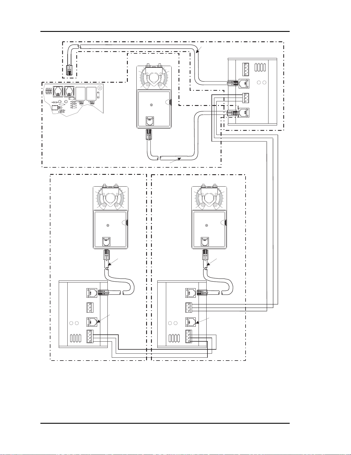
Section 2
Auto-Zone Basic
EXPANSION
ACTUATOR
PJ2PJ1
ZONE CONTROLLER BOARD
SLAVED- ZONE ACTUATOR #2
(WHEN USED)
ZONE ACTUATOR #1
(MASTER)
10
MODULAR CABLE
SLAVED-ZONE ACTUATOR #1
1 10 0
MODULAR CABLE
BYPASS &
SLAVE INTERFACE CARD
CLOSE
OPEN
TB1
GND
FDBK
CLOSE
OPEN
GND
PJ2
FROM ZONE
CONTROLLER
TB2
PJ1
TO ACTUATOR
LD2
OPEN
YS101824
LD1
CLOSE
BYPASSAND
SLAVEINTERFACE
MODULAR
CABLE
BYPASS &
SLAVE INTERFACE CARD
TO ACTUATOR
BYPASSAND
SLAVEINTERFACE
YS101824
PJ1
GND
OPEN
TB2
CLOSE
OPEN
CLOSE
FROM ZONE
CONTROLLER
PJ2
LD2
LD1
FDBK
GND
TB1
OPEN
CLOSE
NOT USED FOR
THIS APPLICATION
BYPASS &
SLAVE INTERFACE CARD
BYPASSAND
SLAVEINTERFACE
CLOSE
LD1
Figure 2-14: Slaved Zone Controller Wiring
YS101824
OPEN
LD2
TO ACTUATOR
PJ1
TB2
FROM ZONE
CONTROLLER
PJ2
TB1
GND
OPEN
CLOSE
FDBK
GND
OPEN
CLOSE
MODULAR
CABLE
NOT USED FOR
THIS APPLICATION
2-20
Installation and Wiring
Page 51

Auto-Zone Basic
Section 2
Room Sensors
The Room Sensor uses a patented flush-mount design to isolate the temperature sensing
element from the housing which mounts flush with the wall surface.
Room Sensors should be located on an inside wall away from direct sunlight or heatproducing equipment such as computers, copiers, etc. Such devices can adversely affect
the accuracy of the sensor. Although the sensor eliminates most of the effects of thermal
coupling to the walls, try to avoid walls which retain large amounts of thermal energy
(such as marble or steel). Walls containing either cold or warm air currents should also be
avoided whenever possible. Avoid locating the sensor in dead air areas of a room. This
will result in slow response to temperature changes in the space.
Figure 2-15: Room Sensor Installation
Mount the sensor approximately 50-60 inches from the floor for best results. The Room
Sensor is designed to mount vertically in a standard 2- by 4-inch electrical box. The sensor may be mounted directly into the drywall where electrical codes do not require low
voltage wiring to be enclosed in conduit. A template is supplied with the sensor to facilitate cutting a hole of the correct size.
Tip: Be careful when cutting the hole to make sure the sensor or the plastic bezel of
the sensor will completely cover the opening.
Tip: If sensors must be installed on walls which are solid and cannot be penetrated,
surface-mounted boxes and raceway can be purchased from your local electrical
distributor.
Installation and Wiring
2-21
Page 52
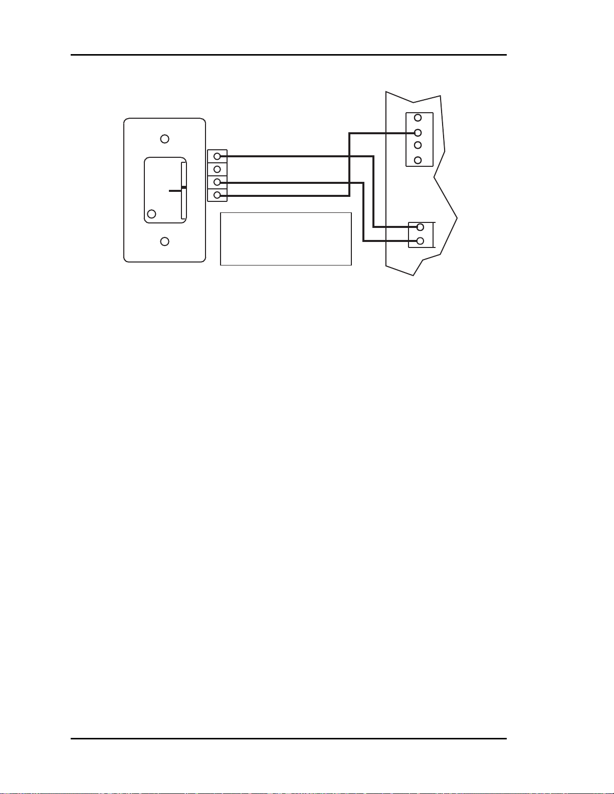
Section 2
Auto-Zone Basic
Zone Controller
Room Sensor
W
A
R
M
E
R
C
O
O
OVR
L
E
R
TMP
GND
AUX
Connection To AUX
Terminal Required Only
When Sensor Is Specified
AUX
+VS
AUX1
AUX2
GND
TEMP
GND
TB1TB1
++
TB2
With Slide Adjust Option
Figure 2-16: Room Sensor Wiring
Connect the terminal labeled GND on the zone sensor to the terminal labeled GND on the
Zone Controller terminal block for the TEMP SENSOR. Connect the terminal labeled
TMP on the zone sensor to the terminal labeled TEMP on the Zone Controller terminal
block for the TEMP SENSOR. If the zone sensor has a setpoint adjust slider, connect the
sensor terminal labeled AUX to the Zone Controller AUX terminal block labeled AUX1.
2-22
Installation and Wiring
Page 53
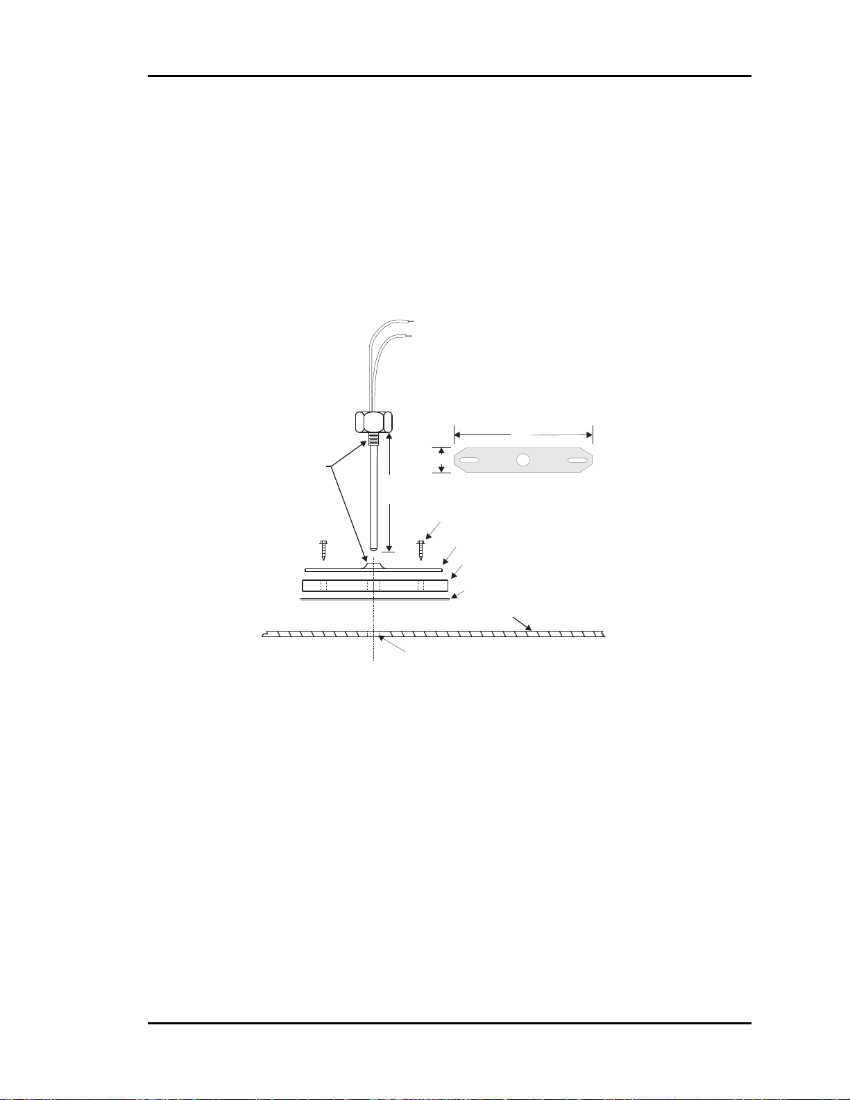
Auto-Zone Basic
Section 2
Supply Air Temperature Sensor
The supply air temperature sensor should be located as close to the rooftop unit dis-
charge as possible for best response. It should also be mounted upstream of the bypass
damper for best results. Locate the sensor in the center of the widest part of the duct. Use
the supplied template and a 5/16" drill to make a hole for the sensor. Install the gasket
over the probe and mount securely to the duct using the supplied sheet metal screws. Be
sure the gasket is compressed to provide an airtight seal. For best accuracy, apply insulation on the outside of the duct, over the sensor. This will help prevent thermal gradients
from affecting the sensor.
Leads Are Non-polarized.
Butt Splice Leads To24Gauge
Wire Minimum. Connect Leads
To "AnalogIn"And "Ground"
At Controller.
4.0"
Thread
Together
5-1/2" (OE230)
11-1/2" (OE231)
3/4"
MountingPlate
1/4" HexHead Sheet MetalScrews
Mounting Plate
Gasket
Adhesive Backed Drill Guide
MountingTemplate
Duct Work
Drill 5/16"Hole In Ductwork For Probe
Figure 2-17: Supply or Return Air Sensor Dimensions and Installation
Installation and Wiring
2-23
Page 54

Section 2
Auto-Zone Basic
Return Air Temperature Sensor
The return air temperature sensor should be located upstream of where the Bypass con-
nects to the return air duct so that the supply air does not affect the reading of the return
air sensor. Avoid locations which will be exposed to extreme outside temperatures. Locate the sensor in the center of the widest part of the duct. Use the supplied template and
a 5/16" drill to make a hole for the sensor. Install the gasket over the probe and mount
securely to the duct using the supplied sheet metal screws. Be sure the gasket is compressed to provide an airtight seal. For best accuracy, apply insulation on the outside of
the duct over the sensor. This will help prevent thermal gradients from affecting the sensor.
Caution: Do not mount the return air sensor in the mixed air section. This will
cause an error in the reading.
2-24
Installation and Wiring
Page 55
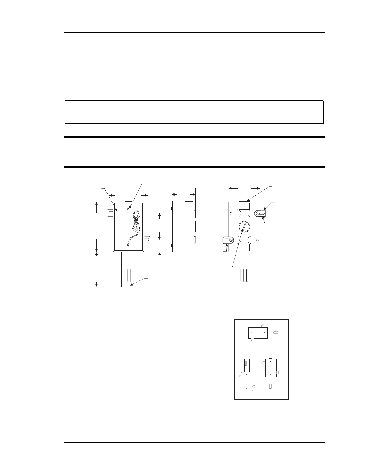
Auto-Zone Basic
Section 2
Outside Air Temperature Sensor
The outside air sensor must be located where it will not be affected by direct sun or heat
producing equipment. Mounting under the eve of a roof is often a good choice.
Caution: Complaints of inaccurate outside sensor readings are very common and
can almost always be shown to be the result of poor sensor location.
Note: All sensors utilize the same type thermistor sensor element. For troubleshooting
sensors, refer to temperature sensor resetting instructions in section 3 of this
manual.
Gasketed Cover
CAUTION!
See Note3
3.00”
Cover
Mounting
Screw - Typ.
2.30”
2.70”
Closure Plug
CAUTION!
See Note 2
0.21" Dia. x 0.73
Lg. Slot - Typ.
4.50”
3.00”
Front View Side View
Notes:
1.)The Outside Air Sensor Must Be
Mounted In A Vertical Position As
Shown (Sensor Tube Pointing
Water Must Not Be
Down).
Allowed To Stand In Sensor
Tube. Rainwater Will Damage
Sensor.
Sensor Must Be Located
Where It Will Not Be Affected By
Direct Sunlight Or Heat Producing
Equipment. If Possible Mount Under
Roof Eave Or Similar Protected
Location. If Sensor Is Not Located
As Specified, Erroneous Outside Air
Temperature Readings Will Result.
2.25”
1.13”
Sensor Tube
CAUTION!
See Note 1
2.)Unused Conduit Opening(s) Must
Have Closure Plugs Installed And Must
Be Coated with Sealing Compound To
Provide Raintight Seal. Water Can
Damage Sensor!
3.)Gasket Must Be Installed Under Cover
Plate To Provide Raintight Seal.
Rainwater Can Damage Sensor!
4.)All Wiring To Be In Accordance With
Local And National Electrical Codes
And Specifications.
Mounting Tab
& Screw - Typ.
Closure Plug
CAUTION!
See Note 2
Back View
Incorrect
See Note #1
Incorrect
Sensor Mounting
Correct
Postion
Mounting Tab
& Screws - Typ.
Figure 2-18: Outside Air Temperature Sensor Dimensions and Installation
Installation and Wiring
2-25
Page 56

Section 2
.
Auto-Zone Basic
Duct Static Pressure Sensor
The duct static pressure sensor is designed to be mounted at the controller or on the
ductwork near the pickup tube and may be connected via its modular plug. If the sensor is mounted on the ductwork, the modular plug must be cut off and 3-conductor
wire spliced onto the sensor leads. If the trunk ducts are properly sized for minimum
pressure drop, the location of the static pickup probe is not particularly critical. It
should ideally be located at right angles to the airflow in a straight section of the supply duct approximately ⅔ the distance of the total length of the supply duct. Also, the
probe should be located not less than 3 duct diameters downstream and 2 duct diame-
ters upstream of any elbow or takeoff. See Figure 1-3 in section 1 of this manual for
general mounting location information.
1.00"
0.55"
1.95"
0.35"
0.15"
0.60"
0.200" (3/16" Tubing Conn.)
0.125" (1/8" Tubing Conn.)
(-)LO
OE271
S.P. Sensor
2.94"
OUT
GND
0.15" DIA.
UP
IN
1.29"
12.0" APPROX
OUT (Black)
GND (Green)
2.20"
2.50"
IN (Red)
Figure 2-19: Duct Static Pressure Sensor Dimensions and Installation
Caution: Mount the static pressure sensor on a vertical surface with the tube tips
pointing downward. Avoid any kinks or sharp bends in the tubing which
runs from the pickup tube to the sensor.
Warning: The plastic housing on the sensor is electrically conductive. Avoid
contact with any electrical components. It is acceptable to mount the
sensor on grounded sheet metal such as ductwork, electrical panels,
etc.
Warning: Use extreme care when mounting the sensor to avoid damage to the
plastic housing. Do not over-tighten the mounting screws! Do not use
mounting screws which are too large for the holes!
2-26
Installation and Wiring
Page 57

Auto-Zone Basic
Tip: Having at least 10-20 feet of tubing between the pick-up tube and the pressure
sensor will improve control performance by acting as a “filter” to remove pressure fluctuations caused by turbulence in the duct.
Section 2
Figure 2-20: Static Pressure Sensor Wiring
Note: Refer to Figure 1-3 in section 1 of this manual for instructions concerning
proper location of the static pressure sensor.
Installation and Wiring
2-27
Page 58
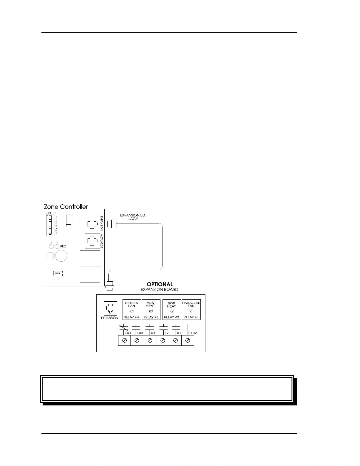
Section 2
Auto-Zone Basic
Auxiliary Relay Board for
Zone Controllers
An optional auxiliary relay board is available for the Zone Controllers. This board pro-
vides additional outputs for the following applications:
• Parallel Fan
• Box Heat
• Auxiliary Heat (typically perimeter type)
• Series Fan
The board comes shipped with a modular cable which plugs directly into the Zone Controller connector marked “Expansion.” After connecting the board, the system will need to be
powered OFF and then ON for the system to recognize the presence of the relay board.
Figure 2-21: Auxiliary Relay Board Layout
Warning: Relay contacts are rated for 24VAC pilot duty only! Do not apply
voltages higher than 24VAC.
2-28
Installation and Wiring
Page 59

Auto-Zone Basic
Section 2
Zone Controller Auxiliary Relay Board
Operation
Relay #1 - Parallel Fan
If the zone is in cooling mode or vent mode, the parallel fan relay will activate any time
the zone temperature drops 0.5°F below the heating setpoint. It de-activates when the
temperature rises 0.5°F above the heating setpoint. The space temperature must be below
the AUX HEAT setpoint in the occupied mode before the Parallel Fan relay can be energized.
Relay #2 - Box Heat
If the zone is in cooling mode or vent mode, the box heat relay will activate any time the
zone temperature drops 1.5°F below the heating setpoint. It de-activates when the temperature rises to within 1.0°F of the heating setpoint. Box heat is not allowed to activate
in the heating mode when there is hot air being supplied by the air handler. This output
was intended to allow zone re-heat while the Zone Manager is satisfying cooling demands in other zones. The space temperature must be below the AUX HEAT setpoint in
the occupied mode before the Box Heat relay can be energized.
Relay #3 - Aux Heat
In the occupied mode, the aux heat relay will activate any time the zone temperature is
0.5°F below the aux heat setpoint. It de-activates when the temperature rises 0.5°F above
the aux heat setpoint. In the unoccupied mode, the aux heat uses the unoccupied heating
setpoint with the same deadband values mentioned above. This prevents the zone from
maintaining the same aux heat setpoint at night that it does during the daytime.
This output was intended to allow zone heating, to augment the normal heating mode,
and also to allow a zone to attempt to satisfy its own heating needs before creating a heating demand at the Zone Manager.
Relay #4 - Series Fan
The series fan relay is energized any time the main fan is running. This includes occu-
pied and unoccupied modes. In the unoccupied mode, the fan can only start when the
zone damper is closed. The controller checks to be sure the damper is closed before starting the fan.
Installation and Wiring
2-29
Page 60

Section 2
Auto-Zone Basic
CommLink IV Interface
The optional CommLink IV is used to transfer communications between controllers on
your control system loops. It can also be used as an interface for connection of a computer to your system. The CommLink IV provides communication with any controller on
the control system through a computer that is running Prism software or it can be used to
communicate with most controllers by using only the Zone Manager. For remote communications, an IP Module Kit can be installed for LAN and Internet connections or a
Remote Link II can be connected for dial-up connections.
Figure 2-22: CommLink IV Interface Communication Wiring
Locate the CommLink near the computer or modem. The cable connections between the
CommLink and the computer or modem should be kept to less than 25 feet.
The CommLink comes complete with computer and modem cables and a plug-in power
supply. There is an optional IP Module that installs into the CommLink and provides
TCP/IP Internet connection and an optional Remote Link II for dial-up connection or
alarm call-outs. The Zone Manager address switch must be set to 17 when the
CommLink is installed on the Auto-Zone Basic Control System. Also the jumper switch
located on the CommLink circuit board must be set for single loop operation. See Figure
2-23 and Figure 2-24 for details.
2-30
Installation and Wiring
Page 61

Auto-Zone Basic
Section 2
Figure 2-23: CommLink IV Interface Connections
Installation and Wiring
2-31
Page 62
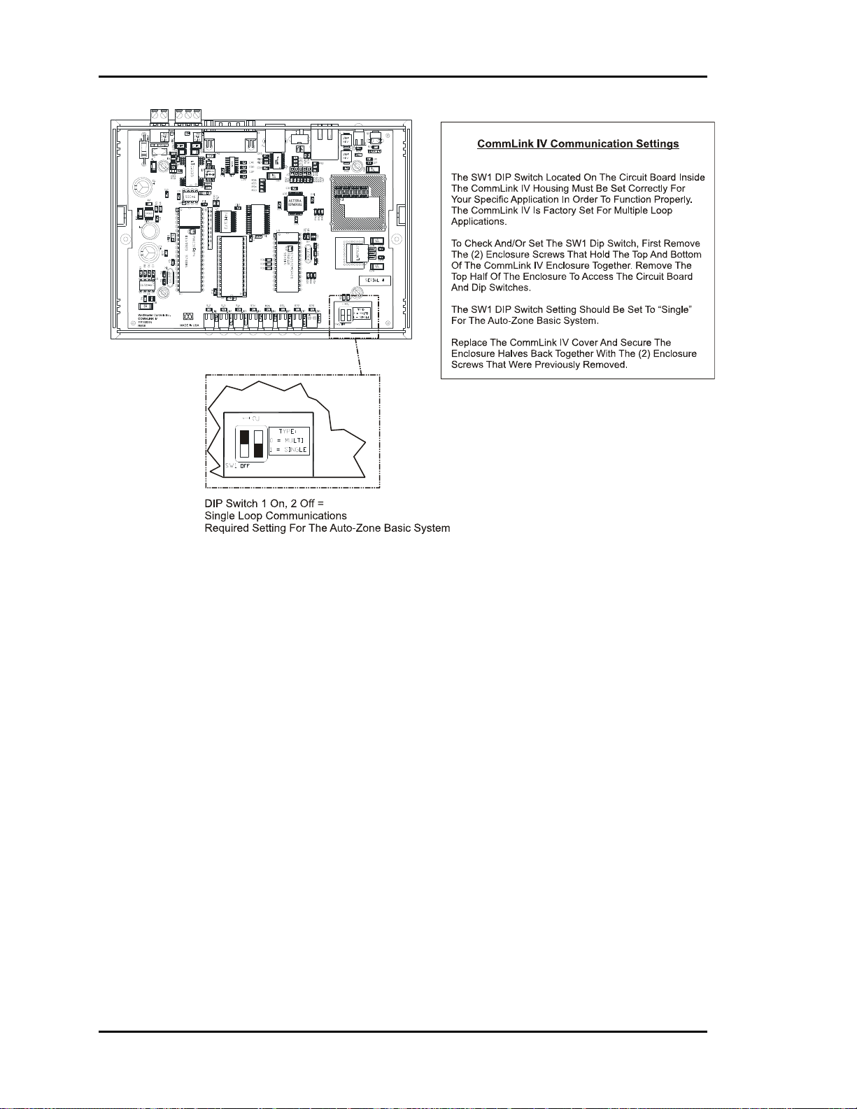
Section 2
Auto-Zone Basic
Figure 2-24: CommLink IV Jumper Switch Settings
2-32
Installation and Wiring
Page 63

Auto-Zone Basic
Section 2
Basic System Worksheet
Project: _______________________ Location ______________________________________________
CommLink Installed: Yes No Remote Link Installed: Yes No Phone:
_________________
Stages of Cooling ____ Stages of Heating ____ Gas Electric Economizer Yes No
Zoning: Pressure Dependent Pressure Independent
Zone
Address
1
2
3
4
5
6
7
8
9
10
11
Air
Zone Description or Location
S SO SA SOA
S SO SA SOA
S SO SA SOA
S SO SA SOA
S SO SA SOA
S SO SA SOA
S SO SA SOA
S SO SA SOA
S SO SA SOA
S SO SA SOA
S SO SA SOA
Damper
Size
Room
Sensor Type
Relay
Exp. Board
AH BH SF PF
AH BH SF PF
AH BH SF PF
AH BH SF PF
AH BH SF PF
AH BH SF PF
AH BH SF PF
AH BH SF PF
AH BH SF PF
AH BH SF PF
AH BH SF PF
12
13
14
15
16
[S=Sensor] [SO=Sensor w/ Override] [SA=Sensor w/ Setpoint adjust] [SOA=Sensor w/ Override & Setpoint adjust]
[AH=Auxiliary Heat] [BH=Box Reheat] [SF=Series Fan Terminal] [PF=Parallel Fan Terminal]
Installation and Wiring
S SO SA SOA
S SO SA SOA
S SO SA SOA
S SO SA SOA
S SO SA SOA
AH BH SF PF
AH BH SF PF
AH BH SF PF
AH BH SF PF
AH BH SF PF
2-33
Page 64

Section 2
Index
Auto-Zone Basic
24VAC-to-24VAC.............................. 16
Actuator Cable .................................... 11
Actuator Clutch................................... 11
Address Sequence ................................. 8
Addressing
Checking ......................................... 18
Incorrect .......................................... 18
Zone Controller................................. 1
Zone Manager ................................... 7
Airflow Restrictions
Preventing ................................. 10, 13
AUX
Terminal.......................................... 22
Aux Heat ............................................. 28
AUX HEAT ........................................ 28
AUX1
Terminal.......................................... 22
Auxiliary Heat..................................... 27
Auxiliary Relay Board ........................ 27
Layout Diagram .............................. 27
Belden No. 82760 ................................. 8
Box Heat ....................................... 27, 28
Bypass Damper
Overview......................................... 10
Wiring ............................................. 12
Bypass Dampers
Insulated.......................................... 10
Rectangular ..................................... 10
Round.............................................. 10
Bypass Wiring Interface Board........... 10
Cable
Actuator .......................................... 11
Belden No. 82760 ............................. 8
Splice ................................................ 8
Cables
Auxiliary Relay Board .................... 14
Flow Sensor .................................... 14
Codes
Wiring ............................................... 1
Color Code............................................ 8
CommLink IV
Connections Diagram...................... 30
Jumper Switch Settings................... 31
Overview......................................... 28
Wiring ............................................. 29
Communication Problems
Addressing Incorrectly.................... 18
Communications Loop.......................... 8
Wiring Overview .............................. 9
Component Locations ........................... 2
Components
Damage To...................................... 16
Zone Manager ................................... 4
Conduit.................................................. 8
Configuration
Daisy Chain....................................... 8
Cooling Mode ..................................... 28
Daisy Chain
Configuration .................................... 8
Damper Actuator
Gears, Damaging............................. 11
Overview......................................... 10
Damper Blade ..................................... 11
Forcing ............................................ 11
Dampers
Tagging ............................................. 1
Dial-Up Connections .......................... 29
Dimensions
Zone Manager ................................... 3
Duct Static Pressure Sensor ................ 25
Mounting......................................... 25
Ductwork
Static Pressures ............................... 12
Electrical Connections
Zone Manager ................................... 6
Energy Efficiency
Improving.................................. 10, 13
Environmental Limitations
Zone Manager ................................... 3
Fluorescent Lights................................. 8
2-34
Installation and Wiring
Page 65

Auto-Zone Basic
Section 2
GND-to-GND ..................................... 16
Heating
Setpoint ........................................... 28
High Pressure Limit Switch
Manual Reset .................................. 12
Incorrect
Wiring ............................................... 8
Installation
Room Sensor................................... 21
SAT or RAT Sensor........................ 23
Zone Manager ................................... 3
Installing
Zone Manager ................................... 3
IP Module Kit ..................................... 29
Kinks................................................... 10
Avoiding ................................... 13, 25
LAN and Internet connections............ 29
Manual Reset
High Pressure Limit Switch............ 12
Metal Shavings ..................................... 5
Metal Strapping............................. 10, 13
Mounting
Duct Static Pressure Sensor ............ 25
Outside Air Sensor.......................... 24
Room Sensor................................... 21
Snap-Track...................................... 14
Supply Air Temperature Sensor ..... 23
Zone Controllers ............................. 14
Zone Manager ................................... 3
Occupied Mode................................... 28
Operation
Auxiliary Relay Board .................... 28
Outside Air Sensor
Installing ......................................... 24
Location .......................................... 24
Mounting......................................... 24
Outside Sensor Readings
Inaccurate........................................ 24
Parallel Fan ................................... 27, 28
Plastic Bezel........................................ 21
Polarity............................................ 1, 16
Prism ................................................... 29
Rectangular Zone Damper
Overview......................................... 13
Remote Link II.................................... 29
Return Air Temperature Sensor
Installing ......................................... 23
Location .......................................... 23
Mounting......................................... 23
Ribbon Cable ........................................ 3
Room Sensor
Installation ...................................... 21
Mounting......................................... 21
Wiring ............................................. 22
Room Sensors
Best Location .................................. 21
Location .......................................... 21
Overview......................................... 21
Round Air Damper.............................. 10
Round Zone Damper
Overview......................................... 13
RS-485 Loop......................................... 8
Safety Device...................................... 12
Sensor
Accuracy ......................................... 21
Series Fan...................................... 27, 28
Setpoints
AUX HEAT .................................... 28
Heating............................................ 28
Sheet Metal Screws............................. 11
Slaved............................................ 10, 13
Slaved Zone Controller Wiring........... 20
Snap-Track
Mounting......................................... 14
Splicing
Cable ................................................. 8
Star Configuration................................. 9
Static Pressure Sensor
Wiring ............................................. 26
Supply Air
Temperature Sensor ........................ 23
Supply Air Temperature Sensor
Location .......................................... 23
Mounting......................................... 23
Sweating
Avoiding ......................................... 13
Improving........................................ 10
System Component
Locations........................................... 2
System Overview
Diagram............................................. 2
Installation and Wiring
2-35
Page 66

Section 2
Auto-Zone Basic
Tagging
Dampers ............................................ 1
TEMP
Terminal.......................................... 22
TEMP SENSOR.................................. 22
Temperature Sensor
Return Air ....................................... 23
Supply Air....................................... 23
Thermistor Sensor............................... 24
Transformers......................................... 8
Unoccupied Mode............................... 28
Vent Mode .......................................... 28
VFDs ..................................................... 8
Wire
Color Code........................................ 8
Wire Color ............................................ 8
Wire Cradles ................................. 10, 13
Wiring ................................................... 1
Bypass Damper ............................... 12
Codes................................................. 1
CommLink IV................................. 29
Communications Loop...................... 9
Incorrect ............................................ 8
Room Sensor................................... 22
Star Configuration............................. 9
Static Pressure Sensor..................... 26
Zone Controller......................... 17, 20
Zone Manager ................................... 5
Worksheet
Basic System................................... 32
Zone Controller
Address Switch Settings ................. 19
Address Switches.............................. 1
Component Diagram....................... 15
Damage Prevention......................... 16
Electrical Connections .................... 16
Setting Address ............................... 19
Slaved Wiring ................................. 20
Wiring ............................................. 17
Zone Controllers
Mounting......................................... 14
Overview......................................... 14
Zone Damper ...................................... 13
Overview......................................... 13
Zone Manager
Addressing Switch ............................ 7
Board................................................. 4
Dimensions ....................................... 3
Electrical Connections ...................... 6
Environmental Limitations ............... 3
Installation ........................................ 3
Mounting........................................... 3
Ribbon Cable .................................... 3
Wiring ............................................... 5
2-36
Installation and Wiring
Page 67

Section 3
Table of Contents
LCD/Keypad Operations...................................................1
Main Screen Access.........................................................................................................1
Data Entry Functions .......................................................................................................2
Zone Summary Screen .....................................................2
Individual Zone Status Screens.......................................3
Zone Manager Status Screens ........................................5
Alarm Status Screens......................................................7
Entering Passcodes .........................................................9
Main Menu Operation.......................................................9
Zone Controller Setpoints..............................................10
Zone Manager Setpoints................................................14
Week Schedules.............................................................................................................14
Holidays.........................................................................................................................15
Setting Time & Date......................................................................................................16
Control Setpoints ...........................................................................................................16
Zone Manager Configuration .........................................20
System Overrides...........................................................24
Zone Manager Operations Summary .............................26
Programming
Page 68

Page 69

Auto-Zone Basic
Section 3
LCD/Keypad Operations
Main Screen
Vent Mode
03/19/02 03:05pm Tue
Occupied
1 Alarm(s) 3
The Auto-Zone Zone Manager is your direct link into the status and setpoints of any
Zone Controller on your communications loop. With the Zone Manager, you can view
any temperature or output condition and change any setpoint to fine tune the operations
of the total system. All keypad operations are simple and straightforward and use noncryptic plain English messages.
The remainder of this section will lead you through the system menus and keypad
operation.
Current Polling Address
Main Screen Access
Keypad Layout
A - Summary
B - Status
C - Status
D - Alarms
# - Menu
Programming 3-1
Select the Zone Controller Summary Screen
Select Individual Zone Status Screens
Select the Zone Manager Status Screens
Select the Alarm Status Screens
Select the Main Menu Screen
Page 70

Section 3
Data Entry Functions
Auto-Zone Basic
A - Abort
Used to exit from screens or from data entry.
Use this key to return to the Main Menu from
any screen in the system.
B - Backup
Use this key to step backwards to previous
screens or setpoints.
C - Clear
If a data entry mistake is made, press this key
to clear the data entry field and start over.
D - Negative
* - Decimal
If entering a setpoint that is negative in value,
press this key for the minus sign.
Use this key as the decimal point when
entering decimal values.
# - Enter
Use this key to close a data entry field and
advance to the next item or screen.
Zone Summary Scr een
To see a summary of all attached Zone Controllers, press the "A" key while the Main
Screen is active. The following screen will appear. Zones are shown in groups of three.
Step to each additional screen by pressing the "#" key. If there are not three units
available for any given screen, the remaining lines on that screen will be blank.
Zone TEMP CLSP HTSP
1 74.2 77.0 74.0
2 73.1 75.0 72.0
3 76.4 75.0 72.0
Zone TEMP CLSP HTSP
4 74.2 77.0 74.0
5 73.1 75.0 72.0
6 76.4 75.0 72.0
etc.
Zone TEMP CLSP HTSP
16 74.2 77.0 74.0
Note: The temperature displayed includes the slide effect offset.
3-2 Programming
Page 71

Auto-Zone Basic
Section 3
Individual Zone Status
Screens
To see the complete status of any attached Zone Controller, press the "B" key while the
Main Screen is active. The following screens will appear. Step to each additional screen
by pressing the "#" key. Press the "A" key to exit before all status screens have been
viewed. If a zone doesn't respond, the screen will display " *** Missing *** ". If the
zone is currently in the Calibration mode, the screen will display "Calibrating." No
status or setpoints are available during calibration.
Note: The top line of every status screen shows the selected zone address.
Status Screen #1
Zone Number 1
Occupied Mode
Voting Unit
Line 2 -
Line 3 -
Status Screen #2
Zone Number 1
Temperature: 75.4
CSP 75.0 HSP 72.0
Slide Adjust.: 0.0
Line 2 - Current Zone Temperature
Line 3 - Current Cooling Setpoint (CSP) & Heating Setpoint
Line 4 - Optional Sensor Slide Adjust effect on Setpoints
Unoccupied Mode
Occupied Mode
Push-button Override
Force Mode Active!
Voting Unit
Non-Voting Unit
(HSP)
Programming 3-3
Page 72

Section 3
Status Screen #3
Auto-Zone Basic
Zone Number 1
Damper Pos 20
Minimum Setpt 20
Maximum Setpt 100
Status Screen #4
Zone Number 1
Auxiliary Heat Off
Series Fan On
Line 2 - Current Zone Damper Position
Line 3 - Currently active Minimum Damper/Airflow
Setpoint. Each mode has its own minimum setpoint.
These modes are vent, cooling and heating.
Line 4 - Currently active Maximum Damper/Airflow
Setpoint. This value is user adjustable and is used in
all modes of operation, unlike the Minimum
Damper/Airflow Setpoint.
Line 2 -
Auxiliary Heat Off
Box Heating On
Aux Heating On
Box & Aux Heat On
Line 3 -
Series Fan On
or
Blank Line if Fan is Off
Line 4 -
Parallel Fan On
or
Blank Line if Fan is Off
3-4 Programming
Page 73

Auto-Zone Basic
Section 3
Zone Manager Status
Screens
To see the Zone Manager status, press the "C" key while the Main Screen is active. The
following screens will appear. Step to each additional screen by pressing the "#" key.
Press the "A" key to exit before all status screens have been viewed.
Status Screen #1
HVAC Status
Supply Air 78.6
Static Press 0.49
Bypass Damper 24%
Line 2 - Current Supply Air Temperature
Line 3 -
Line 4 -
Status Screen #2
HVAC Status
Return Air 75.3
Outdoor Air 70.2
Economizer 20%
Line 2 - Current Return Air Temperature
Line 3 - Current Outdoor Air Temperature
Line 4 - Current Economizer Damper Position if the system is
If the system is configured for VAV operation, this
line shows the current Static Pressure in the duct. It
is displayed in Inches of Water Column.
If the system is configured for VAV operation, this
line shows the current Bypass Damper position
currently required to maintain the displayed amount
of Static Pressure.
configured for Economizer control.
Programming 3-5
Page 74

Section 3
Status Screen #3
Auto-Zone Basic
HVAC Status
Active Cool Stage: 0
Active Heat Stage: 0
Wetbulb Temp: xxx.x
Status Screen #4
HVAC Status
Mavericks 0
Cool Total 0.0
Heat Total 0.0
Line 2 -
Line 3 -
Line 2 - The currently Active Cooling Stages are displayed on
this line. You can see the first two stages from the
LED display on the front panel. This screen allows
you to view systems with more than two stages of
cooling and see how many are active.
Line 3 - The currently Active Heating Stages are displayed on
this line. The same LED information is available for
heating as described above.
Line 4 -
If the optional Economizer Module has been installed
on your system, this line will show the currently
calculated Wetbulb Temperature.
The Zone Manager knows if any units have had a
four-degree demand for at least one hour. It totals
them up and displays this value as the total number of
Maverick Zones.
As the Zone Manager polls its Zone Controllers, it
totals up the heating and cooling demand so it can
make an HVAC decision.
The Cooling Total is displayed on this line.
Line 4 - The Heating Total, from the zone polling, is
displayed on this line.
3-6 Programming
Page 75

Auto-Zone Basic
Section 3
Alarm Status Screens
If the last line on the Main Screen displayed one or more active alarms, you can press the
"D" key while on the Main Screen to display a list of detected alarms. Each screen
displays one alarm at a time. If no alarms are present when you press the "D" key, the
message "No Alarms" will be displayed on the alarm screen.
Status Screen #1
Alarm Status
No Alarms
Line 3 -
Possible Alarm Messages that can be displayed, one
at a time, on this line.
Zone Manager Messages
Bad Supply Air Sensor
Static Sensor Alarm
Damper Feedback Fail
Damper Opening Alarm
Damper Closing Alarm
Auxiliary Alarm
COOLING FAILURE!
HEATING FAILURE!
OAT Broadcast Lost
Zone Controller Messages
Missing Zone 1
Zone Damper Fail 1
Bad Zone Sensor 1
Maverick Zone 1
All Zone Controller messages are followed by the
address of the unit that is causing the alarm.
If any alarms are present, the Alarm LED on the
Front Panel will be active, alerting you at a distance
that an alarm is present.
Programming 3-7
Page 76

Section 3
Alarm Definitions
Auto-Zone Basic
Cooling Failure! or Heating Failure!
Bad Supply Air Sensor or Bad Zone
Sensor
Bypass Feedback Fail
Damper Opening Alarm
Damper Closing Alarm
Static Sensor Alarm
- Once the heating or cooling is activated, the
Supply Air Temperature has 30 minutes to
change by at least 5°F, or the Zone Manager
assumes a mechanical failure has occurred and
generates an alarm.
- The Zone Manager or Zone Controller was
unable to detect the appropriate sensor
installed.
- During calibration the controller does not
receive a signal from the Bypass Damper
Actuator Feedback Pot.
-
The Bypass Damper Actuator does not travel
the full open position on a call to open.
-
The Bypass Damper Actuator does not travel
to its full closed position on a call close.
-
The current static pressure reading has been
above 3.0 inches or below 0.01 inches for more
than 30 seconds.
Missing Zone
Zone Damper Fail
Auxiliary Alarm
Maverick Zone
- The Zone Manager has been out of contact
with a specific zone for 5 consecutive pollings.
-
The zone damper either failed the startup
calibration or it has stopped responding to
commands.
- A contact closure is detected on the AUX2
input
-
The identified zone has exceeded a 4°F heating
or cooling demand for at least 1 hour.
3-8 Programming
Page 77

Auto-Zone Basic
Section 3
Entering Passcodes
Any time you are prompted to enter a passcode, the following screen will appear. The
actual passcode digits are never displayed. Instead, an "X" is placed on the screen for every
digit entered, as a place holder, to allow you to know which digit you are entering. The
default passcode is "1111" and is programmable to any other four-digit value.
Passcode Request
THIS ACTION REQUIRES
PASSCODE CLEARANCE
Enter Passcode: xxxx
Main Menu Operation
To gain access to the system setpoints and configurations, press "#" while on the Main
Screen to select the Main Menu. There are four selections available on the Main Menu.
Selection of the second item, Manager Setpoints, opens a second menu screen, shown
later in this section. To return to the Main Screen from any other screen, press the "A"
key until the Main Screen appears.
Main Menu
1) Read/Reset Zones
2) Manager Setpoints
3) Configure System
4) System Overrides
For detailed information on each of the Main Menu selections, refer to the appropriate
paragraph heading as noted below.
1) Read/Reset Zones
2) Manager Setpoints
3) Configure System
4) System Overrides
Zone Controller Setpoints
Zone Manager Setpoints
Zone Manager Configuration
System Overrides
Programming 3-9
Page 78

Section 3
Auto-Zone Basic
Zone Controller Setpoints
You will be prompted to enter the address of the Zone Controller that you want to read or
reset. If you enter a non-existent zone address, the screen will display "*** Missing ***"
and no setpoint screens will be displayed.
Zone Selection Screen
SELECT ZONE
ENTER ADDRESS: 1
Note: The top line always displays the currently selected Zone Controller and the
controller type.
PD ZONE ADDRESS means a Pressure Dependent Box is selected.
PI ZONE ADDRESS means a Pressure Independent Box is selected.
Setpoint Screen #1
PD ZONE ADDRESS 1
OCCUPIED SETPOINTS
Cooling Setpt: 75 F
Heating Setpt: 72 F
Enter the Occupied Heating and Cooling Setpoints on this
screen. The Heating Setpoint should always be two degrees
below the Cooling Setpoint or the Zone Controller will not
accept the new values. The Zone Manager can't prevent the
entry of invalid setpoints. If invalid setpoints are entered, the
previous settings will be retained by the system and displayed
the next time the Zone Setpoints are accessed.
Cooling Setpoint
Heating Setpoint
Minimum Default Maximum
50°F 75°F 90°F
50°F 72°F 90°F
3-10 Programming
Page 79
Auto-Zone Basic
Section 3
Setpoint Screen #2
PD ZONE ADDRESS 1
UNOCCUPIED SETPOINTS
Cool SetUp...: 10 F
Heat Setback.: -10 F
Enter the Unoccupied Heating and Cooling Setback values on
this screen. The Occupied Cooling Setpoint will be increased
by the Cooling Setback during Unoccupied Mode and the
Heating Setpoint will be decreased by the Heating Setback.
Cool Setback
Heat Setback
Setpoint Screen #3
PD ZONE ADDRESS 1
AuxHeat Setpt: 72 F
Slide Effect.: 3 F
If your Zone Controller has the optional Relay Expansion Board
attached, one of the relays is reserved for an Auxiliary Heating
Relay. Enter that setpoint on the AuxHeat Setpt line. If the
relay board is not installed, this line will not be displayed.
If your Zone Temperature sensor has the optional Setpoint
Adjustment Slide, enter the maximum effect it can have on the
setpoints on the Slide Effect line.
AuxHeat Setpt
Slide Effect
Minimum Default Maximum
0°F 10°F 30°F
0°F -10°F -30°F
Minimum Default Maximum
50°F 72°F 90°F
0°F 3°F 5°F
Note: If slide effect is set to 0°, the push-button override will not function.
Setpoint Screen #4
PD ZONE ADDRESS 1
Max Damper....: 100%
Cool Mode Min.: 5%
Heat Mode Min.: 20%
Programming 3-11
On Pressure Dependent Zones, these setpoints are for damper
position. On Pressure Independent Zones they are for Airflow
(CFM) values, and the text will change to reflect that.
PD Zone Max Damper
PI Zone Max Airflow
PD Zone Cool Mode Min
PI Zone Cool Mode Min
PD Zone Heat Mode Min
PI Zone Heat Mode Min
Minimum Default Maximum
0%
0 CFM
0%
0 CFM
0%
0 CFM
100%
800 CFM
5%
200 CFM
20%
300 CFM
100%
30000 CFM
100%
30000 CFM
100%
30000 CFM
Page 80

Section 3
Setpoint Screen #5A
Auto-Zone Basic
PD ZONE ADDRESS 1
Vent Mode Min.: 50%
Nite Mode Min.: 100%
On Pressure Dependent Zones, the setpoints displayed are for
damper position.
PD Zone Vent Mode Min 0% 50% 100%
PD Zone Nite Mode Min 0% 100% 100%
Setpoint Screen #5B
PD ZONE ADDRESS 1
Vent Mode xxxxx CFM
Nite Mode xxxxx CFM
CFM @1”WG xxxxx CFM
For Pressure Independent Zones the text changes to display
airflow (CFM) values. On the third line - "CFM@1" WG",
enter the appropriate "K" Flow Factor from Table 1-2 of this
manual.
PI Zone Vent Mode Min 0 CFM 500 CFM 30000 CFM
PI Zone Nite Mode Min 0 CFM 0 CFM 30000 CFM
PI Zone CFM @1" WG 0 CFM 2100 CFM 30000 CFM
Minimum Default Maximum
Minimum Default Maximum
Setpoint Screen #6
PD ZONE ADDRESS 1
Overrides..: Global
Damper Mode: Direct
PRESS (*) TO TOGGLE
The Zone Controller will respond to another zone’s pushbutton override if it is configured for global overrides. If single
overrides are selected, the zone will only enter override if its
own push-button is pressed.
The normal damper operation is direct acting, which means it
opens in a clockwise direction. If your system opens in a
counter-clockwise direction, select reverse acting mode.
3-12 Programming
Page 81
Auto-Zone Basic
Section 3
Setpoint Screen #7
PD ZONE ADDRESS 1
Voting Mode: Voting
PRESS (*) TO TOGGLE
Normally, you want a zone to be included in the polling by the
Zone Manager. This allows the demand in that zone to have a
vote in determining the HVAC mode of operation. If you have
a problem zone or an area that you don't want to include in the
voting, select the NonVote mode of operation.
Setpoint Screen #8
PD ZONE ADDRESS 1
Sensor Calibration
Rdg Offset
Zone: 75.4 0.0
Note: The Thermistor Type III Sensors have a 0.4 degree accuracy.
Tip: This calibration offset is also useful as a troubleshooting tool. If you need to
simulate a heating or cooling mode, you can raise or lower the current zone
temperature far enough to put the zone into the desired mode.
If you have a tenant that doesn't agree with the current zone
temperature reading, you can adjust or calibrate the zone
temperature reading.
Enter a positive number if the current reading is too low.
Enter a negative number if the current reading is too high.
Caution: The normal calibration offset should be a fairly small value. If you need
several degrees of offset, there might be a sensor problem or a location
problem.
Programming 3-13
Page 82

Section 3
Auto-Zone Basic
Zone Manager Setpoints
The Zone Manager Setpoints are kept separate from the Zone Manager Configuration
setpoints since these are the most commonly changed values. Enter the number shown
below for the desired selection. When you are finished, press the "A" key to return to the
Main Menu.
Zone Manager Setpoint Menu
1) Control Setpoints
2) Schedules
3) Holidays
4) Time & Date
Week Schedules
Schedule Start Time
WEEK SCHEDULES
Sunday Start Time
Enter Hrs/Mins: 0
(MILITARY FORMAT)
Schedule Stop Time
WEEK SCHEDULES
Sunday Stop Time
Enter Hrs/Mins: 0
(MILITARY FORMAT)
The screens will step through the Start Time and then the Stop
Time for each day of the week. You can quit at any point in
the process by pressing the "A" key.
All times are in 24-hour format, so 5:00 PM would be entered
as 1700.
If both the Start and Stop Times are ZERO, the schedule is in
a continuous OFF mode.
If both the Start and Stop Times are 2359, the schedule is in a
continuous ON mode.
Note: The second line displays which day of the week is currently being programmed.
This automatically increments as you finish the Stop Time and continue to the
next Start Time screen.
3-14 Programming
Page 83

Auto-Zone Basic
Section 3
Holidays
Holiday Day Selection
Program Holidays
Holiday # 1
Start Mon/Day: 101
(EX: 101 = Jan. 1)
The screens will step through the eleven possible holidays one
at a time. Line 2 shows which holiday is currently being
programmed.
Remember to combine the month and day into a single fourdigit value.
EXAMPLE: 704 = July 4th
Holiday Start/Stop Times
Holiday Schedule
Starting Time: 0
Stopping Time: 0
The eleven holidays all use the same Start and Stop
time which is entered on this screen. It is entered in 24-
hour military format, the same as a regular week
schedule.
1225 = December 25th
Programming 3-15
Page 84

Section 3
Auto-Zone Basic
Setting Time & Date
The Zone Manager has its own built-in real time clock. Although the times are displayed
on the Main Screen in a standard 12-hour format, they are programmed using the 24-hour
military format. If the Zone Manager was configured to use its own Internal Schedules,
the Occupied/Unoccupied modes are calculated on the basis of the current real time clock
reading.
Programming Time
Program Time/Date
Day (Sunday=0): 2
Enter Hr.(0-23): 14
Enter Min : 53
Day
Hours (Hr)
- Enter the Day of the Week (0 to 6) with
Sunday = 0
- Enter Hours in 24-Hour Military Format
(1700 = 5:00 PM)
Minutes
- Enter the Minutes (0 to 59)
Programming Date
Program Time/Date
Month (1-12): 3
Day (1-31): 19
Year (00-99): 02
Month
Day
Year
- Enter the Month (1 to 12)
- Enter the Day of the Month (1 to 31)
- Enter the current Year with two digits (00
to 99)
Daylight Savings Adjustments
Daylight Savings
Adjustments Enabled
Press (*) To Toggle
If your area of the country requires Daylight Savings changes,
the Zone Manager can automatically make the adjustment for
you. This used to be the first Sunday in April and the second
Sunday in October. However, the U.S. government has now
decided to arbitrarily change these dates from time to time. So
we recommend that you disable these automatic adjustments
by pressing the "*" key to select Adjustments Disabled and
make the adjustments yourself each year.
3-16 Programming
Page 85

Auto-Zone Basic
Section 3
Control Setpoints
Setpoint Screen #1
Manager Setpoints
Static Press: 0.5”
If you have configured for variable HVAC type, this screen
will be displayed to allow you to enter the controlling Static
Pressure Setpoint.
Static Press
Setpoint Screen #2
Manager Setpoints
Cool Lockout: 50
Heat1 Lockout: 65
Heat2 Lockout: 45
Enter the Mechanical Cooling and Heating Lockouts on this
page. There are two heating lockouts. Heat1 Lockout is for
Stage #1 only, and Heat2 Lockout is for Stages #2 and up.
This allows energy conservation during Spring and Fall
conditions when a single stage of heating could handle the
load.
Cool Lockout
Heat1 Lockout
Heat2 Lockout
Minimum Default Maximum
0.1" 0.5" 2.0"
Minimum Default Maximum
-30°F -30°F 80°F
30°F 65°F 99°F
30°F 45°F 99°F
Programming 3-17
Page 86

Section 3
Setpoint Screen #3
Auto-Zone Basic
Cool Staging: 4 Min
Min Cool Off: 4 Min
Heat Staging: 4 Min
Min Heat Off: 4 Min
The heating and cooling stages must have been off for a
minimum amount of time before they can be activated or reactivated. As each additional stage of heating or cooling is
added, a minimum Staging Delay period must be satisfied
between each additional stage required.
Cool Staging 1 Min 4 Min 30 Min
Min Cool Off 1 Min 4 Min 30 Min
Heat Staging 1 Min 4 Min 30 Min
Min Heat Off 1 Min 4 Min 30 Min
Setpoint Screen #4
Manager Setpoints
Heat/Cool Changeover
Interval....: 15 Min
If the Zone Manager needs to change HVAC modes
between heating and cooling, a Changeover Delay time
must be satisfied first. This prevents "chasing" due to
alternate hot and cold air always being supplied to the
zones after short intervals.
Interval 1 Min 10 Min 30 Min
Minimum Default Maximum
Minimum Default Maximum
Setpoint Screen #5
Economizer Setpoints
Closed Volts: 0.0
Opened Volts: 10.0
3-18 Programming
If the Zone Manager has been configured for Economizer
Control, this screen will appear. You can set the voltages
required to open and closed the damper. Some actuators use a
2-10 VDC signal instead of 0-10 VDC.
If the system is not configured for Economizer Control, no
economizer setpoint screens will appear.
Closed Volts 0.0 VDC 0.0 VDC 10.0 VDC
Opened Volts 0.0 VDC 10.0 VDC 10.0 VDC
Minimum Default Maximum
Page 87

Auto-Zone Basic
Section 3
Setpoint Screen #6
Economizer Setpoints
Econo Enable: 50
Supply Setpt: 50
Min Econo % : 20%
The Econo Enable setpoint is the outdoor air or wetbulb
temperature that enables the Economizer to open past its
minimum position setpoint to control supply air temperature.
The Supply Setpt is the supply air temperature the Economizer
tries to maintain.
The Min Econo % is the position the economizer holds during
occupied mode when it is not enabled for operation due to
outdoor air or wetbulb temperature.
Econo Enable
Supply Setpt
Min Econo % 0% 20% 100%
Setpoint Screen #7
Economizer Setpoints
Economizer Interval
Seconds.....: 50.0
During Economizer control, the Economizer damper is
allowed to move open or closed, as required at a rate
controlled by this value. Use this setpoint to speed up or slow
down the operation of your economizer. The larger the
number, the slower the damper will move.
Minimum Default Maximum
-30°F 50°F 99°F
45°F 50°F 80°F
Interval .1 50 90.0
Setpoint Screen #8
Sensor Rdg Offset
SAT.: 82.9 0.0
RAT.: 77.2 0.0
OAT.: 70.2 0.0
As described in the Zone Controller section, the Thermistor
Type III sensor readings can be calibrated. The Outdoor Air
Calibration Offset only applies to the Zone Manager that has
the sensor installed. It has no effect on the global broadcast
value of outdoor air.
Supply Sensor SAT
Return Sensor RAT
Outdoor Sensor OAT
Minimum Default Maximum
Minimum Default Maximum
-100.0°F 0.0°F +100.0°F
-100.0°F 0.0°F +100.0°F
-100.0°F 0.0°F +100.0°F
Programming 3-19
Page 88

Section 3
Auto-Zone Basic
Zone Manager
Configuration
Normally, the configuration setpoints need to be entered only one time. For this reason,
they occupy their own menu location and need not be addressed during normal setpoint
read and reset operations. To access the configuration setpoints, press the "3" key while
on the Main Menu screen.
Note: On initial power up, the system must be configured before it can be successfully
operated.
Configuration Screen #1
Last Zone Addr: 1
First Zone Addr: 1
Cooling Stages: 1
Heating Stages: 1
Caution: The zones should be consecutively addressed with no skipped address
locations. If an address is skipped, the Zone Manager will presume there
is a missing zone, and an alarm will occur.
The Zone Manager needs to know the address range of the
attached Zone Controllers to be polled. Enter the addresses of
the first and last zones here.
The quantity of cooling and heating stages is also entered on
this screen.
Last Zone Addr 1 1 16
First Zone Addr 1 1 16
Cooling Stages 0 1 6
Heating Stages 0 1 6
Minimum Default Maximum
3-20 Programming
Page 89

Auto-Zone Basic
Section 3
Configuration Screen #2
Heat Type.: Electric
Fan Mode.: Constant
PRESS (*) TO TOGGLE
The Zone Manager can control electric or gas heating. Each
type of heat has its own protection limits built into the Zone
Manager software.
The Zone Manager can also operate the fan in one of two
modes:
Constant (Continuous) running during occupied hours.
Cycle with heating or cooling during occupied hours.
The fan always cycles with heating or cooling during
unoccupied hours.
Configuration Screen #3
Economizer: Enabled
PRESS (*) TO TOGGLE
The Zone Manager has the ability to control the Economizer
operation. To initiate Economizer operation, select Enabled.
To toggle between the two Economizer modes, press the "*"
key.
Configuration Screen #4
HVAC Type: Variable
PRESS (*) TO TOGGLE
The Zone Manager normally reads the duct static pressure
and controls it via the bypass damper. If your system doesn't
require static pressure control, select the Constant mode of
operation. To toggle between the two modes, press the "*"
key.
Programming 3-21
Page 90

Section 3
Configuration Screen #5
Auto-Zone Basic
Bypass Act: Direct
PRESS (*) TO TOGGLE
The Zone Manager Bypass Damper normally opens in a
clockwise direction. If your bypass damper opens in a counterclockwise direction, select reverse acting instead of direct
acting operation. To toggle between the two modes, press the
"*" key.
Configuration Screen #6
Zone Manager
Uses Schedule #: 0
0 = Internal Clock
1-8 = External Clock
The Zone Manager normally uses its own real-time clock and
an internal week schedule to determine the Occupied/
Unoccupied mode of operation. The Zone Manager does have
the ability to use a global broadcast from another scheduling
device on the communications loop if a more powerful schedule
is required. If an external schedule is used, the range of
schedule numbers is 1 to 8.
Configuration Screen #7
Press (*) To Force
Recalibration Of The
Static Press. Sensor
<#> To Skip This...
The Zone Manager only calibrates the static pressure sensor
one time. That occurs on the initial powerup, so it is vital that
the sensor be attached before the system is ever powered up. If
you weren't able to do this or accidentally activated the system
before the sensor was available, you can force it to restart and
calibrate the static pressure sensor by pressing the "*" key. If
you don't need to re-calibrate, simply press the "#" key to skip
over this item.
3-22 Programming
Page 91

Auto-Zone Basic
Section 3
Configuration Screen #8
Enter New Passcode
CODE: xxxx
[Must Be 4 Digits]
Press <A> To Skip!
As mentioned earlier, the default passcode is "1111". This
code must be entered before any configuration or setpoint
changes can occur. If you would like to change this default
passcode, enter four digits on this screen. The value entered
must be between 1000 and 9999 to be a valid code. Values
from 0000 to 0999 will be rejected and the last valid code will
be retained.
Caution: If you forget your passcode, you WILL BE locked out of your system!
Tip: The BackDoor Passcode that will always get you into the system is "9288." This
passcode should not be given to the casual users of your system.
Programming 3-23
Page 92

Section 3
Auto-Zone Basic
System Overrides
The Zone Manager provides some user-selectable override modes. This allows you to
troubleshoot the system or set up temporary conditions for those situations when normal
operation of the system is not required.
Override Screen #1
0) AUTO (Time Clock)
1) FORCE Occupied
2) FORCE Unoccupied
3) FAN ONLY [Mode 0]
The Zone Manager defaults to the Auto mode of operation when
first powered up. Any force modes entered will be retained in
non-volatile memory. The unit will resume the force mode of
operation any time the power is cycled.
-
0) Auto
1) Occupied
2) Night
3) Fan Only
Use internal schedules for Day/Night
Mode
-
Forced to Continuous Day or Occupied
Mode
-
Forced to Continuous Night or Unoccupied
Mode. If the Forced Occupied Binary Input
Contact is closed, this mode will override it
to OFF. Use the Auto mode programmed
for continuous Unoccupied operation if you
want to use the Forced Occupied Binary
Input Contact.
This is the mode that is active whenever
you see the Purge Cycle message being
displayed. It disables any heating or cooling
and forces all the boxes to move their
dampers to the full 100 percent open
position. You can use this mode any time
you want to manually purge your building.
3-24 Programming
Page 93

Auto-Zone Basic
Section 3
Override Screen #2
ZONE FORCE MODES
Force to MINIMUM 0
Force to MAXIMUM 0
[0= Normal 1=Force]
The Zone Controller Dampers can all be forced at the same
time to their Minimum or Maximum Damper/Airflow
Setpoints. On Pressure Independent systems, this feature is
useful during air balance operations.
Enter a "1" next to the desired force mode to make it active.
Enter "0" to disable the force mode.
Programming 3-25
Page 94
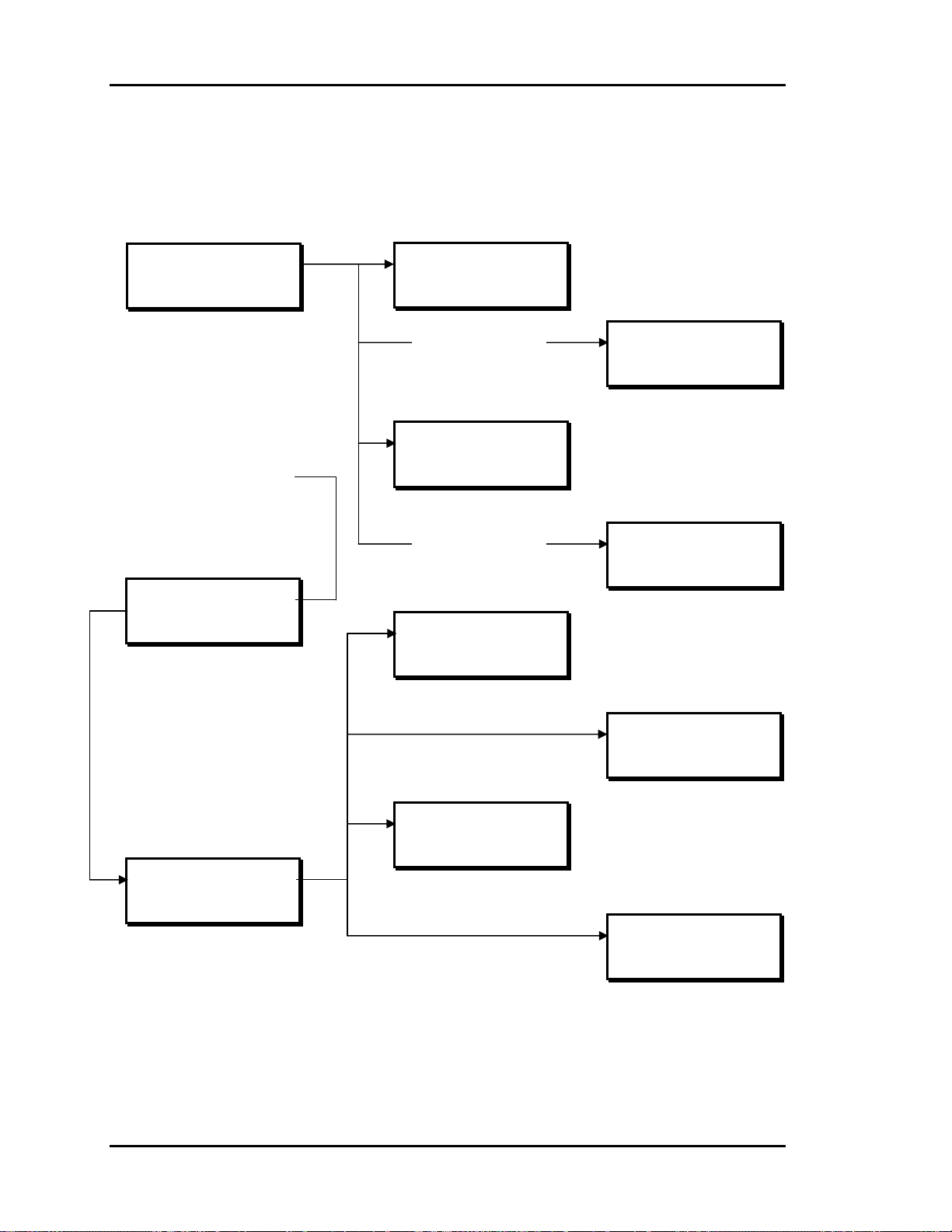
Section 3
Auto-Zone Basic
Zone Manager Operations Summary
1) Read/Reset Zones
2) Manager Setpoints
3) Configure System
4) System Overrides
Main Screen
Vent Mode
06/05/96 08:05am Wed
Occupied
1 Alarm(s) 3
Main Menu Screen
Press “#” Key
Zone Summary Screens
Press “A” Key
Zone TEMP CLSP HTSP
1 74.2 77.0 74.0
2 73.1 75.0 72.0
3 76.4 75.0 72.0
Zone Status Screens
Press “B” Key
Zone Manager Status Screen
Press “C” Key
HVAC Status
Supply Air 56.4
Static Press. 0.49"
Bypass Damper 24%
Alarm Status Screen
Press “D” Key
Control Setpoints Screen
Press “1” Key
Manager Setpoints
Static Press: 0.50”
Zone Number 1
Occupied Mode
Voting Unit
Alarm Status
No Alarms
Schedules Screen
Press “2” Key
WEEK SCHEDULES
Sunday Start Time
Enter Hrs/Mins: 0
(MILITARY FORMAT)
Time & Date Screen
Press “4” Key
Program Time/Date
Day (Sunday=0): 3
Enter Hr. (0-23): 9
Enter Min. : 25
Zone Manager Menu Screen
Press “2” Key
1) Control Setpoints
2) Schedules
3) Holidays
4) Time & Date
Holidays Screen
Press “3” Key
Program Holidays
Holiday # 1
Start Mon/Day: 0
(EX: 101 = Jan. 1)
3-26 Programming
Page 95

Auto-Zone Basic
Index
Section 3
"K" Flow Factor.................................. 12
# - Enter Button..................................... 2
# - Menu Button.................................... 1
# Key................................................. 2, 9
* - Decimal Button................................ 2
1111....................................................... 9
24-Hour Format .................................. 14
A - Abort Button................................... 2
A - Summary Button............................. 1
A Key.................................................... 2
Active Cooling Stages .......................... 6
Active Heating Stages........................... 6
Address Range.................................... 20
Airflow (CFM) Setpoint ..................... 11
Airflow (CFM) Values........................ 12
Alarm
Definitions ........................................8
Status Screens ................................... 7
Alarm LED............................................ 7
Auto Mode.......................................... 24
Aux Heating On.................................... 4
AuxHeat Setpt..................................... 11
Auxiliary Alarm................................ 7, 8
Auxiliary Heat Off................................ 4
Auxiliary Heating Relay..................... 11
B - Backup Button ................................ 2
B - Status Button................................... 1
B Key.................................................... 3
Back Door Passcode ........................... 23
Bad Supply Air Sensor .....................7, 8
Bad Zone Sensor............................... 7, 8
Box & Aux Heat On ............................. 4
Box Heating On .................................... 4
Buttons
# - Enter ............................................2
# - Menu............................................ 1
* - Decimal........................................ 2
A - Abort........................................... 2
A - Summary..................................... 1
B - Backup ........................................ 2
B - Status........................................... 1
C - Clear............................................ 2
C - Status........................................... 1
D - Alarms......................................... 1
D - Negative...................................... 2
Bypass Damper
Direct Acting................................... 22
Reverse Acting................................ 22
Bypass Damper Position....................... 5
Bypass Feedback Fail ........................... 8
C - Clear Button.................................... 2
C - Status Button................................... 1
C Key.................................................... 5
Calibrating ............................................ 3
Calibration Offset ...............................13
CFM @1”WG xxxxx CFM................. 12
Changeover Delay Time..................... 18
Closed Volts........................................ 18
Configuration
Internal Week Schedule.................. 22
Real-Time Clock............................. 22
Configure System.................................. 9
Control Setpoints .......................... 14, 17
Zone Manager................................. 14
Cool Lockout ...................................... 17
Cool Mode Min................................... 11
Cool SetUp.......................................... 11
Cool Staging .......................................18
Cooling.................................................. 4
Cooling Failure ..................................... 8
COOLING FAILURE........................... 7
Cooling Setback.................................. 11
Cooling Setpoint ................................. 10
Cooling Setpt ...................................... 10
Cooling Stages.................................... 20
Cooling Total........................................ 6
CSP ....................................................... 3
Current Cooling Setpoint...................... 3
Current Zone Temperature ................... 3
D - Alarms Button................................. 1
D – Negative Button ............................ 2
D Key.................................................... 7
Damper Closing Alarm..................... 7, 8
Damper Feedback Fail.......................... 7
Programming 3-27
Page 96

Section 3
Auto-Zone Basic
Damper Mode: Direct......................... 12
Damper Opening Alarm.................... 7, 8
Damper Position Setpoint............. 11, 12
Damper Positions................................ 12
Data Entry Functions ............................ 2
Daylight Savings................................. 16
Default passcode................................... 9
Direct Acting
Bypass Damper............................... 22
Damper Position.............................. 12
Duct Static Pressure............................ 21
Econo Enable Setpoint........................ 19
Economizer Damper Position............... 5
Economizer Interval............................ 19
Economizer Operation
Zone Manager................................. 21
Economizer Setpoints ......................... 18
Electric Heat .......................................21
Entering Passcodes ............................... 9
Fan Mode
Continuous...................................... 21
Cycle............................................... 21
FAN ONLY ........................................ 24
Fan Operation
Unoccupied Hours .......................... 21
First Zone Addr................................... 20
Force Mode Active ............................... 3
Force Modes .......................................24
FORCE Occupied ............................... 24
FORCE Unoccupied ........................... 24
Gas Heat.............................................. 21
Global Broadcast................................. 22
Global Overrides................................. 12
Heat
Electric............................................ 21
Gas .................................................. 21
Heat Mode Min................................... 11
Heat Staging........................................ 18
Heat/Cool Changeover........................ 18
Heat1 Lockout..................................... 17
Heat2 Lockout..................................... 17
Heating.................................................. 4
Heating Failure ..................................... 8
HEATING FAILURE!.......................... 7
Heating Lockout .................................17
Heating Setback.................................. 11
Heating Setpoint .............................3, 10
Heating Setpt....................................... 10
Heating Stages .................................... 20
Heating Total ........................................ 6
Holiday Start/Stop Times.................... 15
Holidays
Zone Manager........................... 14, 15
HSP....................................................... 3
Inches of Water..................................... 5
Internal Week Schedule...................... 22
Invalid Setpoints................................. 10
K Flow Factor..................................... 12
Keypad Layout...................................... 1
Keypad Operations ...............................1
Keys
# ....................................................... 9
# - Enter ............................................2
# - Menu............................................ 1
# - Next Screen .................................2
* - Decimal........................................ 2
A ....................................................... 2
A - Abort........................................... 2
A - Summary..................................... 1
B ....................................................... 3
B - Backup ........................................ 2
B - Status........................................... 1
C ....................................................... 5
C - Clear............................................ 2
C - Status........................................... 1
C - Zone Manager Status .................. 5
D - Alarm.......................................... 7
D - Alarms......................................... 1
D - Negative...................................... 2
Last Zone Addr................................... 20
LCD Operations.................................... 1
Location Problem................................ 13
Main Menu
Operation ..........................................9
Main Screen.......................................... 1
Manager Setpoints ................................ 9
Maverick Zone.................................. 7, 8
Maverick Zones..................................... 6
Max Damper ....................................... 11
Maximum Airflow
Setpoints.......................................... 25
3-28 Programming
Page 97

Auto-Zone Basic
Section 3
Maximum Damper
Setpoints.......................................... 25
Maximum Damper/Airflow Setpoint.... 4
Mechanical Cooling Lockout.............. 17
MILITARY FORMAT ....................... 14
Min Cool Off....................................... 18
Min Econo % ...................................... 19
Min Heat Off....................................... 18
Minimum Airflow
Setpoints.......................................... 25
Minimum Damper Setpoints............... 25
Minimum Damper/Airflow Setpoint..... 4
Missing............................................ 3, 10
Missing Zone .................................... 7, 8
Caution............................................ 20
New Passcode ..................................... 23
Night Mode......................................... 24
Nite Mode Min.................................... 12
Nite Mode xxxxx CFM....................... 12
No Alarms............................................. 7
NonVote Mode.................................... 13
Non-Voting Unit................................... 3
OAT Broadcast Lost............................. 7
Occupied Heating and
Cooling Setpoints............................ 10
Occupied Mode..................................... 3
Opened Volts ...................................... 18
Outdoor Air Calibration Offset........... 19
Outdoor Air Temperature ..................... 5
Outdoor Sensor ................................... 19
Overrides....................................... 12, 24
Overrides..: Global.............................. 12
Parallel Fan Off..................................... 4
Parallel Fan On ..................................... 4
Passcode
Back Door....................................... 23
Passcode Request.................................. 9
Passcodes .............................................. 9
PD ZONE ADDRESS......................... 10
PD Zone Cool Mode Min ................... 11
PD Zone Heat Mode Min.................... 11
PD Zone Max Damper........................ 11
PD Zone Nite Mode Min .................... 12
PD Zone Vent Mode Min ................... 12
PI ZONE ADDRESS.......................... 10
PI Zone CFM @1" WG ...................... 12
PI Zone Cool Mode Min..................... 11
PI Zone Heat Mode Min..................... 11
PI Zone Max Airflow.......................... 11
PI Zone Nite Mode Min...................... 12
PI Zone Vent Mode Min..................... 12
Polling Mode....................................... 13
Polling Range...................................... 20
Pressure Dependent Box..................... 10
Pressure Independent Box .................. 10
Programming
Day.................................................. 16
Hours............................................... 16
Minutes ........................................... 16
Month.............................................. 16
Year................................................. 16
Programming Date.............................. 16
Programming Time............................. 16
Push-button Override............................ 3
Push-Button Override
Won't Work..................................... 11
Read/Reset Zones .................................9
Real Time Clock................................. 16
Real-Time Clock
Configuration.................................. 22
Relay Expansion Board ......................11
Return Air Temperature........................ 5
Return Sensor...................................... 19
Reverse Acting
Bypass Damper............................... 22
Damper Position.............................. 12
Schedules
Zone Manager................................. 14
Screens
Zone Selection ................................ 10
Sensor Calibration............................... 13
Sensor Problem................................... 13
Sensor Slide Adjust............................... 3
Series Fan Off....................................... 4
Series Fan On........................................ 4
Setpoint
Airflow (CFM)................................ 11
Cooling............................................ 10
Heating............................................ 10
Setpoint Adjustment Slide.................. 11
Programming 3-29
Page 98

Section 3
Auto-Zone Basic
Setpoints
Adjustment Slide............................. 11
AuxHeat.......................................... 11
Cooling.............................................. 3
Damper Position........................ 11, 12
Heating.............................................. 3
Invalid............................................. 10
Maximum Airflow.......................... 25
Maximum Damper.......................... 25
Maximum Damper/Airflow.............. 4
Minimum Airflow........................... 25
Minimum Damper........................... 25
Minimum Damper/Airflow............... 4
Occupied Heating and Cooling....... 10
Static Pressure................................. 17
Zone Controller............................... 10
Zone Manager................................. 14
Setting Time & Date........................... 16
Single Overrides ................................. 12
Slide Effect.......................................... 11
Staging Delay Period .......................... 18
Start Time............................................ 14
Static Press.......................................... 17
Static Pressure....................................... 5
Static Pressure Sensor
Re-Calibrate.................................... 22
Static Pressure Setpoint ...................... 17
Static Sensor Alarm.......................... 7, 8
Status
Zone Manager................................... 5
Status Screens
Alarm ................................................ 7
Stop Time............................................ 14
Summary
Zone Controllers ............................... 2
Supply Air Temperature ....................... 5
Supply Sensor ..................................... 19
Supply Setpt........................................ 19
System
Locked Out...................................... 23
System Overrides............................ 9, 24
Thermistor Type III Sensors............... 13
Time & Date
Setting............................................. 16
Zone Manager................................. 14
Unoccupied Heating and Cooling
Setback............................................ 11
Unoccupied Hours
Fan Operation .................................21
Unoccupied Mode................................. 3
Vent....................................................... 4
Vent Mode Min................................... 12
Vent Mode xxxxx CFM...................... 12
Voting Mode....................................... 13
Voting Unit ........................................... 3
Week Schedules
Zone Manager................................. 14
Wetbulb Temperature ........................... 6
Zone CLSP............................................ 2
Zone Controller............................. 1, 3, 8
Setpoints...................................... 9, 10
Zone Controller Alarms........................ 7
Zone Controller Dampers
Forced ............................................. 25
Zone Controllers
Summary........................................... 2
Zone Damper Fail............................. 7, 8
Zone Damper Position .......................... 4
Zone HTSP............................................ 2
Zone Manager
Configuration.............................. 9, 20
Control Setpoints ............................ 14
Economizer Operation.................... 21
Holidays.................................... 14, 15
Operations......................................... 1
Operations Summary ...................... 26
Schedules ........................................ 14
Setpoints...................................... 9, 14
Status Screens ................................... 5
Time & Date ................................... 14
Week Schedules.............................. 14
Zone Manager Alarms .......................... 7
Zone Selection Screen ........................ 10
Zone Status Screens.............................. 3
Zone TEMP........................................... 2
Zones
Read/Reset ........................................ 9
ZoneTemperature Reading.................. 13
3-30 Programming
Page 99

Auto-Zone Basic
Notes
Section 3
Programming 3-31
Page 100

Section 3
Notes
Auto-Zone Basic
3-32 Programming
 Loading...