

Page 1

AutoCAD Raster Design 2010
User’s Guide
April 2009
Page 2

©
2009 Autodesk, Inc. All Rights Reserved. Except as otherwise permitted by Autodesk, Inc., this publication, or parts thereof, may not be
reproduced in any form, by any method, for any purpose.
Certain materials included in this publication are reprinted with the permission of the copyright holder.
Trademarks
The following are registered trademarks or trademarks of Autodesk, Inc., in the USA and other countries: 3DEC (design/logo), 3December,
3December.com, 3ds Max, ADI, Alias, Alias (swirl design/logo), AliasStudio, Alias|Wavefront (design/logo), ATC, AUGI, AutoCAD, AutoCAD
Learning Assistance, AutoCAD LT, AutoCAD Simulator, AutoCAD SQL Extension, AutoCAD SQL Interface, Autodesk, Autodesk Envision, Autodesk
Insight, Autodesk Intent, Autodesk Inventor, Autodesk Map, Autodesk MapGuide, Autodesk Streamline, AutoLISP, AutoSnap, AutoSketch,
AutoTrack, Backdraft, Built with ObjectARX (logo), Burn, Buzzsaw, CAiCE, Can You Imagine, Character Studio, Cinestream, Civil 3D, Cleaner,
Cleaner Central, ClearScale, Colour Warper, Combustion, Communication Specification, Constructware, Content Explorer, Create>what's>Next>
(design/logo), Dancing Baby (image), DesignCenter, Design Doctor, Designer's Toolkit, DesignKids, DesignProf, DesignServer, DesignStudio,
Design|Studio (design/logo), Design Web Format, Discreet, DWF, DWG, DWG (logo), DWG Extreme, DWG TrueConvert, DWG TrueView, DXF,
Ecotect, Exposure, Extending the Design Team, Face Robot, FBX, Filmbox, Fire, Flame, Flint, FMDesktop, Freewheel, Frost, GDX Driver, Gmax,
Green Building Studio, Heads-up Design, Heidi, HumanIK, IDEA Server, i-drop, ImageModeler, iMOUT, Incinerator, Inferno, Inventor, Inventor
LT, Kaydara, Kaydara (design/logo), Kynapse, Kynogon, LandXplorer, LocationLogic, Lustre, Matchmover, Maya, Mechanical Desktop, Moonbox,
MotionBuilder, Movimento, Mudbox, NavisWorks, ObjectARX, ObjectDBX, Open Reality, Opticore, Opticore Opus, PolarSnap, PortfolioWall,
Powered with Autodesk Technology, Productstream, ProjectPoint, ProMaterials, RasterDWG, Reactor, RealDWG, Real-time Roto, REALVIZ,
Recognize, Render Queue, Retimer,Reveal, Revit, Showcase, ShowMotion, SketchBook, Smoke, Softimage, Softimage|XSI (design/logo),
SteeringWheels, Stitcher, Stone, StudioTools, Topobase, Toxik, TrustedDWG, ViewCube, Visual, Visual Construction, Visual Drainage, Visual
Landscape, Visual Survey, Visual Toolbox, Visual LISP, Voice Reality, Volo, Vtour, Wire, Wiretap, WiretapCentral, XSI, and XSI (design/logo).
The following are registered trademarks or trademarks of Autodesk Canada Co. in the USA and/or Canada and other countries:
Backburner,Multi-Master Editing, River, and Sparks.
The following are registered trademarks or trademarks of MoldflowCorp. in the USA and/or other countries: Moldflow, MPA, MPA
(design/logo),Moldflow Plastics Advisers, MPI, MPI (design/logo), Moldflow Plastics Insight,MPX, MPX (design/logo), Moldflow Plastics Xpert.
All other brand names, product names or trademarks belong to their respective holders.
Disclaimer
THIS PUBLICATION AND THE INFORMATION CONTAINED HEREIN IS MADE AVAILABLE BY AUTODESK, INC. "AS IS." AUTODESK, INC. DISCLAIMS
ALL WARRANTIES, EITHER EXPRESS OR IMPLIED, INCLUDING BUT NOT LIMITED TO ANY IMPLIED WARRANTIES OF MERCHANTABILITY OR
FITNESS FOR A PARTICULAR PURPOSE REGARDING THESE MATERIALS.
Published by:
Autodesk, Inc.
111 Mclnnis Parkway
San Rafael, CA 94903, USA
Page 3

Contents
Chapter 1 Introduction to AutoCAD Raster Design 2010 . . . . . . . . . . . 1
What is New in AutoCAD Raster Design 2010 . . . . . . . . . . . . . . . 1
Accessing the Raster Design Home Page . . . . . . . . . . . . . . . . . . 4
About AutoCAD Raster Design dialog box . . . . . . . . . . . . . . . . . 5
Installation Requirements . . . . . . . . . . . . . . . . . . . . . . . . . 5
Supported Image Formats . . . . . . . . . . . . . . . . . . . . . . . . . 5
Image Portability . . . . . . . . . . . . . . . . . . . . . . . . . . . . . . 6
AutoCAD Raster Design History . . . . . . . . . . . . . . . . . . . . . . 7
Chapter 2 Inserting and Correlating Images . . . . . . . . . . . . . . . . . 9
Inserting Images . . . . . . . . . . . . . . . . . . . . . . . . . . . . . . 9
Inserting Local Images Using the Insert Image Dialog Box . . . . . 10
Inserting an Image from the Internet Using the Insert Image
Dialog Box . . . . . . . . . . . . . . . . . . . . . . . . . . . . . 12
Inserting an Image from an FTP Site Using the Insert Image
Dialog Box . . . . . . . . . . . . . . . . . . . . . . . . . . . . . 14
Inserting an Image Using the Command Line . . . . . . . . . . . 16
Adding Image Sources to Favorites . . . . . . . . . . . . . . . . . 18
Assigning a Color Map to an Image . . . . . . . . . . . . . . . . . 18
Creating New Images . . . . . . . . . . . . . . . . . . . . . . . . 20
Correlating Images . . . . . . . . . . . . . . . . . . . . . . . . . . . . 21
Correlating an Image During Insertion . . . . . . . . . . . . . . . 21
Using Quick Insert . . . . . . . . . . . . . . . . . . . . . . . . . 22
iii
Page 4

Specifying Correlation Settings . . . . . . . . . . . . . . . . . . . 23
Adjusting the Image Frame Before Insertion . . . . . . . . . . . . 27
Correlating an Image After Insertion . . . . . . . . . . . . . . . . 28
Matching Image Points . . . . . . . . . . . . . . . . . . . . . . . 28
Moving an Image . . . . . . . . . . . . . . . . . . . . . . . . . . 29
Scaling an Image . . . . . . . . . . . . . . . . . . . . . . . . . . 30
Rubbersheeting an Image . . . . . . . . . . . . . . . . . . . . . . 31
Chapter 3 Saving Images . . . . . . . . . . . . . . . . . . . . . . . . . . . 39
Saving an Image . . . . . . . . . . . . . . . . . . . . . . . . . . . . . . 39
Saving Images with AutoCAD Save . . . . . . . . . . . . . . . . . . . . 41
Embedding Images in a Drawing . . . . . . . . . . . . . . . . . . . . . 42
Saving an Image to Another File Name, Type, or Location . . . . . . . . 43
Saving an Image to an FTP Site . . . . . . . . . . . . . . . . . . . . . . 45
Capturing an Image . . . . . . . . . . . . . . . . . . . . . . . . . . . . 47
Exporting Images . . . . . . . . . . . . . . . . . . . . . . . . . . . . . 48
Exporting an Image . . . . . . . . . . . . . . . . . . . . . . . . . 49
Exporting an Image to an FTP Site . . . . . . . . . . . . . . . . . 51
Exporting a World File . . . . . . . . . . . . . . . . . . . . . . . 52
Correlation Output Types . . . . . . . . . . . . . . . . . . . . . . 54
Encoding and Data Organization Methods . . . . . . . . . . . . . 54
Chapter 4 Changing Image Properties . . . . . . . . . . . . . . . . . . . . 57
AutoCAD Properties . . . . . . . . . . . . . . . . . . . . . . . . . . . . 57
Image Display Properties . . . . . . . . . . . . . . . . . . . . . . . . . 58
Image Display Quality . . . . . . . . . . . . . . . . . . . . . . . . . . . 58
Image Frame Display . . . . . . . . . . . . . . . . . . . . . . . . . . . 59
Image Layer . . . . . . . . . . . . . . . . . . . . . . . . . . . . . . . . 60
Linetype of an Image Frame . . . . . . . . . . . . . . . . . . . . . . . . 61
Foreground Color of a Bitonal Image . . . . . . . . . . . . . . . . . . . 61
Transparency Color of an Image . . . . . . . . . . . . . . . . . . . . . 62
Unused Color for Transparent Color . . . . . . . . . . . . . . . . . . . 63
Chapter 5 Managing Images and Insertions . . . . . . . . . . . . . . . . . 65
Controlling the Image Manager Toolspace . . . . . . . . . . . . . . . . 65
Modifying the Item View Layout . . . . . . . . . . . . . . . . . . 65
Copying Information to the Clipboard . . . . . . . . . . . . . . . 66
Managing Image Display and Data . . . . . . . . . . . . . . . . . . . . 67
Zooming to an Image . . . . . . . . . . . . . . . . . . . . . . . . 67
Changing the Color Map of an Image . . . . . . . . . . . . . . . 68
Adding a Visual Elevation Key to a DEM Image . . . . . . . . . . 69
Creating Another Insertion of an Image . . . . . . . . . . . . . . 70
Displaying Point Data . . . . . . . . . . . . . . . . . . . . . . . . 71
Showing and Hiding Images . . . . . . . . . . . . . . . . . . . . 72
iv | Contents
Page 5

Changing the Display Order of Images . . . . . . . . . . . . . . . 73
Erasing an Image . . . . . . . . . . . . . . . . . . . . . . . . . . 74
Detaching an Image . . . . . . . . . . . . . . . . . . . . . . . . . 74
Unloading/Reloading an Image . . . . . . . . . . . . . . . . . . . 75
Changing the Active Path . . . . . . . . . . . . . . . . . . . . . . 75
Changing the Saved Path . . . . . . . . . . . . . . . . . . . . . . 76
Chapter 6 Modifying Images . . . . . . . . . . . . . . . . . . . . . . . . . 79
Selecting an Image . . . . . . . . . . . . . . . . . . . . . . . . . . . . 79
Controlling Image Frames . . . . . . . . . . . . . . . . . . . . . . . . . 81
Undoing Edits to an Image . . . . . . . . . . . . . . . . . . . . . . . . 81
Snapping to COGO Points . . . . . . . . . . . . . . . . . . . . . . . . 82
Cleaning Up Images . . . . . . . . . . . . . . . . . . . . . . . . . . . . 82
Deskewing an Image . . . . . . . . . . . . . . . . . . . . . . . . 83
Removing Speckles from an Image . . . . . . . . . . . . . . . . . 84
Adjusting the Image Bias . . . . . . . . . . . . . . . . . . . . . . 86
Reversing the Light and Dark Shades in an Image . . . . . . . . . 88
Mirroring an Image . . . . . . . . . . . . . . . . . . . . . . . . . 88
Touching Up an Image . . . . . . . . . . . . . . . . . . . . . . . 89
Image Processing . . . . . . . . . . . . . . . . . . . . . . . . . . . . . 91
Adjusting Images with the Histogram . . . . . . . . . . . . . . . 92
Adjusting the Brightness and Contrast of an Image . . . . . 92
Maximizing Details in an Image . . . . . . . . . . . . . . . 96
Converting a Color Image to Grayscale . . . . . . . . . . . 98
Converting a Grayscale or Color Image to Bitonal . . . . . 100
Making Tonal Adjustments to an Image . . . . . . . . . . 101
Convolving an Image . . . . . . . . . . . . . . . . . . . . . . . 105
Reducing Harshness and Noise in an Image . . . . . . . . 105
Median Filter . . . . . . . . . . . . . . . . . . . . . . . . . 106
Making Differences in Shading More Distinct . . . . . . . 107
Lowpass Filtering . . . . . . . . . . . . . . . . . . . . . . 108
Highpass Filters . . . . . . . . . . . . . . . . . . . . . . . 109
Edge Enhancements Filters . . . . . . . . . . . . . . . . . 110
Shift and Difference Edge Enhancements Filters . . . . . . 110
Laplace Edge Enhancements Filters . . . . . . . . . . . . . 110
Gradient Directional Edge Enhancements Filters . . . . . . 111
Matched Filter Edge Enhancements Filters . . . . . . . . . 111
Using Bitonal Filters . . . . . . . . . . . . . . . . . . . . . 112
Changing Image Density . . . . . . . . . . . . . . . . . . 115
Setting the Color Depth for an Image . . . . . . . . . . . . 116
Using the Palette Manager . . . . . . . . . . . . . . . . . . . . . . . . 118
Manipulating the Color Table . . . . . . . . . . . . . . . . . . . 118
Changing Selected Colors in the Image Palette . . . . . . . 118
Combining Selected Colors in the Image Palette . . . . . . 120
Designating a Transparent Color . . . . . . . . . . . . . . 121
Selecting a Color Directly from the Image . . . . . . . . . 122
Contents | v
Page 6

Removing Duplicate Entries from the Image Palette . . . . 123
Resetting the Image Palette . . . . . . . . . . . . . . . . . 124
Importing and Exporting Image Palettes . . . . . . . . . . . . . 125
Importing an Image Palette . . . . . . . . . . . . . . . . . 125
Exporting an Image Palette . . . . . . . . . . . . . . . . . 128
Displaying Image Palette Information . . . . . . . . . . . 129
Converting Grayscale Images to Paletted Images . . . . . . 130
Controlling Palette Views . . . . . . . . . . . . . . . . . . . . . 131
Controlling the Display of Unused Colors . . . . . . . . . 131
Controlling the Display of Transparent Colors . . . . . . . 132
Controlling the Display of Color Values . . . . . . . . . . 133
Sorting the Color Table . . . . . . . . . . . . . . . . . . . 134
Adding and Removing Columns from the List
Window . . . . . . . . . . . . . . . . . . . . . . . . . . 135
Masking Images . . . . . . . . . . . . . . . . . . . . . . . . . . . . . 136
Creating a New Mask . . . . . . . . . . . . . . . . . . . . . . . 137
Creating a New Mask Using the Command Line . . . . . . . . . 138
Changing an Existing Mask . . . . . . . . . . . . . . . . . . . . 138
Changing the Image Mask Properties . . . . . . . . . . . . 139
Changing an Existing Mask Using the Command
Line . . . . . . . . . . . . . . . . . . . . . . . . . . . . . 140
Enabling or Disabling a Mask . . . . . . . . . . . . . . . . 141
Clipping an Image . . . . . . . . . . . . . . . . . . . . . . . . . 142
Converting a Mask to Image Clips . . . . . . . . . . . . . . . . 143
Cropping Images . . . . . . . . . . . . . . . . . . . . . . . . . . . . . 144
Line Cropping . . . . . . . . . . . . . . . . . . . . . . . . . . . 145
Circular Cropping . . . . . . . . . . . . . . . . . . . . . . . . . 145
Rectangular Cropping . . . . . . . . . . . . . . . . . . . . . . . 146
Diagonal Cropping . . . . . . . . . . . . . . . . . . . . . . . . . 147
Polygonal Cropping . . . . . . . . . . . . . . . . . . . . . . . . 147
Aligned Rectangular Cropping . . . . . . . . . . . . . . . . . . . 148
Removing (Rubbing) Images . . . . . . . . . . . . . . . . . . . . . . . 149
Rubbing a Raster Line . . . . . . . . . . . . . . . . . . . . . . . 149
Rubbing a Raster Arc . . . . . . . . . . . . . . . . . . . . . . . . 150
Rubbing a Raster Circle . . . . . . . . . . . . . . . . . . . . . . 151
Rubbing Multiple Line Segments . . . . . . . . . . . . . . . . . 151
Rubbing Raster Data Within a Circular Region . . . . . . . . . . 152
Rubbing Raster Data Within a Diagonal Region . . . . . . . . . 153
Rubbing Raster Data Within a Polygonal Region . . . . . . . . . 154
Rubbing Raster Data Within a Rectangular Region . . . . . . . . 155
Remove Raster Using Existing Vector Geometry . . . . . . . . . 155
Removing Raster Entities Using REM Commands . . . . . . . . . 156
Removing a Line, Arc, or Circle Using Smart Pick . . . . . 157
Removing a REM Line Primitive . . . . . . . . . . . . . . . 158
Removing a REM Arc Primitive . . . . . . . . . . . . . . . 158
Removing a REM Circle Primitive . . . . . . . . . . . . . . 159
vi | Contents
Page 7

Merging Objects . . . . . . . . . . . . . . . . . . . . . . . . . . . . . 160
Merging Images . . . . . . . . . . . . . . . . . . . . . . . . . . 160
Merging Vectors into a Raster Image . . . . . . . . . . . . . . . 161
Selecting Pen Widths for Vector Merge . . . . . . . . . . . . . . 162
Chapter 7 Raster Entity Manipulation . . . . . . . . . . . . . . . . . . . 165
Characteristics of REM Objects . . . . . . . . . . . . . . . . . . . . . 166
How REM Objects Are Associated with an Image . . . . . . . . . 166
Deciding Which Image to Use REM Commands On . . . . . . . 166
AutoCAD Properties of REM Objects . . . . . . . . . . . . . . . 167
REM Objects and Non-REM Edits . . . . . . . . . . . . . . . . . 167
Defining REM Region Objects . . . . . . . . . . . . . . . . . . . . . . 168
Defining a REM Rectangular Region . . . . . . . . . . . . . . . . 169
Defining a REM Polygonal Region . . . . . . . . . . . . . . . . . 170
Defining a REM Diagonal Region . . . . . . . . . . . . . . . . . 171
Defining a REM Circular Region . . . . . . . . . . . . . . . . . . 172
Defining a Region From an Existing Vector Object . . . . . . . . 174
Removing Part of a Region Object . . . . . . . . . . . . . . . . . 175
Defining REM Enhanced Bitonal Regions . . . . . . . . . . . . . . . . 176
Defining REM Primitive Objects . . . . . . . . . . . . . . . . . . . . . 178
Defining a REM Line Primitive . . . . . . . . . . . . . . . . . . 180
Defining a REM Circle Primitive . . . . . . . . . . . . . . . . . . 181
Defining a REM Arc Primitive . . . . . . . . . . . . . . . . . . . 183
Defining a REM Primitive Using Smart Pick . . . . . . . . . . . . 184
Defining a REM Primitive From Existing Vectors . . . . . . . . . 185
Changing the Linetype of a Primitive Object . . . . . . . . . . . 186
Manipulating REM Objects . . . . . . . . . . . . . . . . . . . . . . . 187
Editing REM Objects . . . . . . . . . . . . . . . . . . . . . . . . 187
Resizing a REM Object . . . . . . . . . . . . . . . . . . . . . . . 189
Using REM Operations . . . . . . . . . . . . . . . . . . . . . . . 191
Trimming and Extending REM Lines . . . . . . . . . . . . 191
Filleting REM Lines . . . . . . . . . . . . . . . . . . . . . 192
Offsetting REM Objects . . . . . . . . . . . . . . . . . . . 193
Smoothing REM Linework . . . . . . . . . . . . . . . . . . 194
Defining REM Objects Partially Outside the Image . . . . . . . . 195
Using REM to Delete Raster Data . . . . . . . . . . . . . . . . . 195
Clearing REM Objects . . . . . . . . . . . . . . . . . . . . . . . 197
Merging REM Objects into an Image . . . . . . . . . . . . . . . 198
Converting REM Objects to a New Raster Image . . . . . . . . . 199
Using REM Transparency . . . . . . . . . . . . . . . . . . . . . 200
Using REM Copy To Clipboard Command . . . . . . . . . . . . 200
Separating Raster Linework Using Knife . . . . . . . . . . . . . . 201
Chapter 8 Converting Raster Entities to Vector . . . . . . . . . . . . . . 203
Configuring VTools . . . . . . . . . . . . . . . . . . . . . . . . . . . 204
Contents | vii
Page 8

ProdNameShort Options . . . . . . . . . . . . . . . . . . . . . . 204
Dynamic Input Settings . . . . . . . . . . . . . . . . . . . . . . 204
Using SmartCorrect . . . . . . . . . . . . . . . . . . . . . . . . . . . 205
Vectorizing Raster Geometry . . . . . . . . . . . . . . . . . . . . . . . 206
Vectorizing Raster Lines and Polylines . . . . . . . . . . . . . . 207
Vectorizing Raster Rectangles . . . . . . . . . . . . . . . . . . . 212
Vectorizing Raster Circles . . . . . . . . . . . . . . . . . . . . . 213
Vectorizing Raster Arcs . . . . . . . . . . . . . . . . . . . . . . . 215
Following Polylines . . . . . . . . . . . . . . . . . . . . . . . . . . . 217
Using the Polyline Follower . . . . . . . . . . . . . . . . . . . . 219
Using the Contour Follower . . . . . . . . . . . . . . . . . . . . 220
Using the 3D Polyline Follower . . . . . . . . . . . . . . . . . . 223
Vectorizing Raster Text . . . . . . . . . . . . . . . . . . . . . . . . . . 225
Creating Single-Line Vector Text . . . . . . . . . . . . . . . . . 226
Creating Multiline Vector Text . . . . . . . . . . . . . . . . . . 228
Using Text Recognition . . . . . . . . . . . . . . . . . . . . . . 230
Entering Settings for Text Recognition . . . . . . . . . . . 230
Recognizing and Converting Text . . . . . . . . . . . . . . 232
Using the Verify Text Window . . . . . . . . . . . . . . . . . . . 234
View Window Options . . . . . . . . . . . . . . . . . . . . . . . 235
Edit Pane Options . . . . . . . . . . . . . . . . . . . . . . . . . 235
Chapter 9 Raster Snapping . . . . . . . . . . . . . . . . . . . . . . . . . 237
Specifying Raster Snap Settings . . . . . . . . . . . . . . . . . . . . . 237
Snap Modes . . . . . . . . . . . . . . . . . . . . . . . . . . . . . . . 238
Chapter 10 Configuring Raster Design . . . . . . . . . . . . . . . . . . . . 241
Changing the Quick Bar Visibility . . . . . . . . . . . . . . . . . . . . 241
Changing the Image Frame Visibility . . . . . . . . . . . . . . . . . . 242
Setting the Default Internet Location for Images . . . . . . . . . . . . 242
Setting the Options . . . . . . . . . . . . . . . . . . . . . . . . . . . 244
Contour Vector Separation Options . . . . . . . . . . . . . . . . 244
Correlation Defaults . . . . . . . . . . . . . . . . . . . . . . . . 245
Correlation Search Paths . . . . . . . . . . . . . . . . . . . . . . 247
General Vector Separation Options . . . . . . . . . . . . . . . . 249
General VTool Settings . . . . . . . . . . . . . . . . . . . . . . . 250
Image Detach Method . . . . . . . . . . . . . . . . . . . . . . . 252
Image Defaults . . . . . . . . . . . . . . . . . . . . . . . . . . . 253
Image Mask Options . . . . . . . . . . . . . . . . . . . . . . . . 254
Image Thumbnails . . . . . . . . . . . . . . . . . . . . . . . . . 255
Inserting Images From GSX or ESP . . . . . . . . . . . . . . . . 256
Locking Method for Image Files . . . . . . . . . . . . . . . . . . 258
Message Display Method . . . . . . . . . . . . . . . . . . . . . 259
Mouse Settings . . . . . . . . . . . . . . . . . . . . . . . . . . . 260
New Image Defaults . . . . . . . . . . . . . . . . . . . . . . . . 261
viii | Contents
Page 9

QSave Preference . . . . . . . . . . . . . . . . . . . . . . . . . . 262
Raster Design Startup Options . . . . . . . . . . . . . . . . . . . 263
Raster Entity Detection Settings . . . . . . . . . . . . . . . . . . 264
REM Settings . . . . . . . . . . . . . . . . . . . . . . . . . . . . 265
Rub and Crop Line Width . . . . . . . . . . . . . . . . . . . . . 266
Remove Under Method . . . . . . . . . . . . . . . . . . . . . . 268
Vector Merge Settings . . . . . . . . . . . . . . . . . . . . . . . 268
VTools Follower Settings . . . . . . . . . . . . . . . . . . . . . . 270
Appendix A Troubleshooting and Reference Guide . . . . . . . . . . . . . 273
Troubleshooting . . . . . . . . . . . . . . . . . . . . . . . . . . . . . 273
Correcting Image Display Order using REGEN . . . . . . . . . . 273
Raster Snap Troubleshooting . . . . . . . . . . . . . . . . . . . 274
Plotting Raster Images . . . . . . . . . . . . . . . . . . . . . . . 274
Images that are Not Editable . . . . . . . . . . . . . . . . . . . . 274
Problems Inserting Images from the Internet . . . . . . . . . . . 275
Sharing Projects with Images from Different Locations . . . . . . 276
Command-Line Commands . . . . . . . . . . . . . . . . . . . . . . . 276
AutoCAD Commands for Images . . . . . . . . . . . . . . . . . . . . 285
Image Menu . . . . . . . . . . . . . . . . . . . . . . . . . . . . . . . 286
Toolbars . . . . . . . . . . . . . . . . . . . . . . . . . . . . . . . . . 288
Raster Design Toolbar . . . . . . . . . . . . . . . . . . . . . . . 288
Raster Entity Manipulation Toolbars . . . . . . . . . . . . . . . 294
The Quick Bar . . . . . . . . . . . . . . . . . . . . . . . . . . . 298
Appendix B Raster Design Dialog Boxes . . . . . . . . . . . . . . . . . . . 301
About AutoCAD Raster Design Box . . . . . . . . . . . . . . . . . . . 301
Assign Multispectral Band Dialog Box . . . . . . . . . . . . . . . . . . 301
Band Assignment Color Map Dialog Box . . . . . . . . . . . . . . . . 301
Bitonal Filters Dialog Box . . . . . . . . . . . . . . . . . . . . . . . . 302
Change Density Dialog Box . . . . . . . . . . . . . . . . . . . . . . . 303
Choose a New Directory Dialog Box . . . . . . . . . . . . . . . . . . . 303
Choose a Resource File Directory Dialog Box . . . . . . . . . . . . . . 304
Coordinate System Assignment Dialog Box . . . . . . . . . . . . . . . 305
Data Organization Dialog Box . . . . . . . . . . . . . . . . . . . . . . 307
Despeckle Dialog Box . . . . . . . . . . . . . . . . . . . . . . . . . . 307
Display Manager Raster Layer Capture Dialog Box . . . . . . . . . . . 307
Drafting Settings Dialog Box . . . . . . . . . . . . . . . . . . . . . . . 308
Raster Snap Tab (Drafting Settings Dialog Box) . . . . . . . . . . 309
Edit Status Dialog Box . . . . . . . . . . . . . . . . . . . . . . . . . . 310
Encoding Method Dialog Box . . . . . . . . . . . . . . . . . . . . . . 311
Export Dialog Box . . . . . . . . . . . . . . . . . . . . . . . . . . . . 311
Export Options Dialog Box . . . . . . . . . . . . . . . . . . . . . . . 313
Export Palette Dialog Box . . . . . . . . . . . . . . . . . . . . . . . . 314
GeoTIFF Coordinate System Properties Dialog Box . . . . . . . . . . . 315
Contents | ix
Page 10

Grid Parameters Dialog Box . . . . . . . . . . . . . . . . . . . . . . . 315
Histogram Dialog Box . . . . . . . . . . . . . . . . . . . . . . . . . . 316
Brightness/Contrast Tab (Histogram Dialog Box) . . . . . . . . . 316
Equalize Tab (Histogram Dialog Box) . . . . . . . . . . . . . . . 318
Threshold Tab (Histogram Dialog Box) . . . . . . . . . . . . . . 320
Color to Grayscale Tab (Histogram Dialog Box) . . . . . . . . . . 321
Tonal Adjustment Tab (Histogram Dialog Box) . . . . . . . . . . 322
Image Data Properties Dialog Box . . . . . . . . . . . . . . . . . . . . 324
Image Filters Dialog Box . . . . . . . . . . . . . . . . . . . . . . . . . 324
Image Insertion Dialog Box . . . . . . . . . . . . . . . . . . . . . . . 325
Assign Color Map Tab (Image Insertion Dialog Box) . . . . . . . 325
Source Tab (Image Insertion Dialog Box) . . . . . . . . . . . . . 326
Modify Tab (Image Insertion Dialog Box) . . . . . . . . . . . . . 327
Insertion Tab (Image Insertion Dialog Box) . . . . . . . . . . . . 328
Transform Tab (Image Insertion Dialog Box) . . . . . . . . . . . 329
Image Manager Toolspace . . . . . . . . . . . . . . . . . . . . . . . . 330
Image Insertions View (Image Manager Toolspace) . . . . . . . . 331
Image Data View (Image Manager Toolspace) . . . . . . . . . . . 332
Image Select Dialog Box . . . . . . . . . . . . . . . . . . . . . . . . . 335
Import Data Dialog Box . . . . . . . . . . . . . . . . . . . . . . . . . 336
Import Palette Dialog Box . . . . . . . . . . . . . . . . . . . . . . . . 337
Insert Image Dialog Box . . . . . . . . . . . . . . . . . . . . . . . . . 338
Median Filter Dialog Box . . . . . . . . . . . . . . . . . . . . . . . . 340
Mirror Dialog Box . . . . . . . . . . . . . . . . . . . . . . . . . . . . 341
Multi-frame Select Dialog Box . . . . . . . . . . . . . . . . . . . . . . 341
New Image Dialog Box . . . . . . . . . . . . . . . . . . . . . . . . . . 342
New Image Mask Dialog Box . . . . . . . . . . . . . . . . . . . . . . 343
New Palette Color Insertion Dialog Box . . . . . . . . . . . . . . . . . 344
Palette Assignment Color Map Dialog Box . . . . . . . . . . . . . . . 345
Palette Color Map Definition Dialog Box . . . . . . . . . . . . . . . . 345
Palette Information Dialog Box . . . . . . . . . . . . . . . . . . . . . 348
Palette Manager Dialog Box . . . . . . . . . . . . . . . . . . . . . . . 348
Raster Data Query Dialog Box . . . . . . . . . . . . . . . . . . . . . . 350
Raster Design Options Dialog Box . . . . . . . . . . . . . . . . . . . . 351
Image Defaults Tab (Raster Design Options Dialog Box) . . . . . 351
Feature Settings Tab (Raster Design Options Dialog Box) . . . . . 352
Image Mask Tab (Raster Design Options Dialog Box) . . . . . . . 353
New Image Tab (Raster Design Options Dialog Box) . . . . . . . 354
Paths Tab (Raster Design Options Dialog Box) . . . . . . . . . . 355
REM Tab (Raster Design Options Dialog Box) . . . . . . . . . . . 357
Raster Entity Detection Tab (Raster Design Options Dialog
Box) . . . . . . . . . . . . . . . . . . . . . . . . . . . . . . . 357
User Preferences Tab (Raster Design Options Dialog Box) . . . . 358
Vector Merge Tab (Raster Design Options Dialog Box) . . . . . . 359
VTools Follower Tab (Raster Design Options Dialog Box) . . . . . 360
VTools General Tab (Raster Design Options Dialog Box) . . . . . 362
x | Contents
Page 11

Raster Pen Settings Dialog Box . . . . . . . . . . . . . . . . . . . . . . 363
Recognition Character Sets Dialog Box . . . . . . . . . . . . . . . . . 364
Rubbersheet - Set Control Points Dialog Box . . . . . . . . . . . . . . 364
Save As Dialog Box . . . . . . . . . . . . . . . . . . . . . . . . . . . . 366
Select a Lock File Directory Dialog Box . . . . . . . . . . . . . . . . . 367
Select Coordinate System (Export) Dialog Box . . . . . . . . . . . . . 368
Select Coordinate System (Insert) Dialog Box . . . . . . . . . . . . . . 369
Select Global Coordinate System Dialog Box . . . . . . . . . . . . . . 369
Select Working Coordinate System Dialog Box . . . . . . . . . . . . . 369
Target Color Dialog Box . . . . . . . . . . . . . . . . . . . . . . . . . 370
Temporary File Location Dialog Box . . . . . . . . . . . . . . . . . . . 370
Text Recognition Setup Dialog Box . . . . . . . . . . . . . . . . . . . 371
Transparency Color Dialog Box . . . . . . . . . . . . . . . . . . . . . 373
Vector Separation Options Dialog Box . . . . . . . . . . . . . . . . . 373
General Tab (Vector Separation Options Dialog Box) . . . . . . . 373
Contour Tab (Vector Separation Options Dialog Box) . . . . . . 375
Verify Text/Table Dialog Box . . . . . . . . . . . . . . . . . . . . . . . 376
VText Edit Dialog Box . . . . . . . . . . . . . . . . . . . . . . . . . . 379
Glossary . . . . . . . . . . . . . . . . . . . . . . . . . . . . . 381
Index . . . . . . . . . . . . . . . . . . . . . . . . . . . . . . . 403
Contents | xi
Page 12

xii
Page 13

Introduction to AutoCAD Raster Design 2010
The AutoCAD Raster Design User's Guide includes conceptual, procedural, and reference
details about the tools and features found in AutoCAD Raster Design 2010.
This chapter provides information to help you get acquainted with Raster Design requirements,
capabilities, and history.
1
What is New in AutoCAD Raster Design 2010
AutoCAD Raster Design 2010 builds on the features introduced in Raster Design
2009.
New in Raster Design 2010
DescriptionFunction
Citrix support
AutoCAD Raster Design 2010 is now available for use on Citrix XenApp v4.5 and 5.0
for use with AutoCAD Map 3D 2010.
Additional Autodesk product support
Improved image format support
AutoCAD Raster Design 2010 can now be
used with AutoCAD P&ID 2010 and
Autodesk Topobase 2010.
Support for TIFF and BIL image formats
had been improved. In addition, AutoCAD
Raster Design 2010 now includes 64-bit
MrSID Codec support.
1
Page 14

New in Raster Design 2010
DescriptionFunction
Updated ribbon
New in Raster Design 2009
64-bit support
Discrete-themed data handling
Vista ribbon-style interface
The ribbon interface has been updated to
be even easier to use.
DescriptionFunction
AutoCAD Raster Design 2010 supports
both the 32-bit and 64-bit environments
of its hosting Autodesk products. This will
allow you to easily and confidently install
AutoCAD Raster Design 2010 on any supporting application, using any of its supported operating systems.
Discrete-themed data is a form of raster
data commonly used to represent such
things as land cover, zoning, and any other
classified data. Coupled with the continuous-themed data handling required for
working with elevations, this provides a
much more robust environment for accurately using raster grid data.
This interface presents command options
in a concise visual format, enabling you to
quickly select commands based on the
work you are doing. Moving between applications is now quick and intuitive. The
ribbon is both customizable and expandable, so it can be optimized for each user
and to meet each company's standards.
New in Raster Design 2008
DescriptionFunction
Read images in these formats:Support for additional image formats
■ QuickBird TIFF
■ Landsat FAST
2 | Chapter 1 Introduction to AutoCAD Raster Design 2010
Page 15

New in Raster Design 2008
DescriptionFunction
■ NITF (National Image Transmission
Format)
Vectorization improvements
Editing multi-resolution images
Image embedding
Improved insert options
Enhanced image capture
Improved Despeckle
Prompts during vectorization operations
can display conveniently near the cursor,
using AutoCAD Dynamic Input. Grips appear on previously vectorized segments to
facilitate editing.
Edit MrSID, ECW, and JPEG2000 images,
then save changes in JPEG2000 format.
Embed one or more bitonal images inside
the drawing for convenience of image
transfer and management.
The insert process has been improved with
better image preview handling, support
for multi-frame images, better indication
when default settings are being applied,
and enhanced control over coordinate
transforms.
When used with AutoCAD Map 3D, Raster
Design can capture FDO (Feature Data
Object) data, either in source format, or as
stylized by Display Manager.
Procedures are streamlined to make despeckle operations easier and more effective.
New in Raster Design 2007
ESRI Grid format support
What is New in AutoCAD Raster Design 2010 | 3
DescriptionFunction
Read images in this format.DTED format support
Read images in both ASCII and binary versions of this format.
Page 16

New in Raster Design 2007
DescriptionFunction
Coordinate system transformation
New in Raster Design 2006
REM Operations tools
Raster Data Query dialog box
Transform and edit complex image data
Write to more image formats
Automatic assignment of the Autodesk
Map coordinate system code when inserting a GeoTIFF or DEM file. Also, automatic
assignment of the correct EPSG code when
exporting to GeoTIFF format.
DescriptionFunction
Edit images at the pixel level.Touchup tools for bitonal images
Extend and trim raster lines to intersections, add corner fillets, and offset lines.
Display data about the pixel under the
cursor, such as color value, elevation, and
coordinates in the specified coordinate
system.
When using Autodesk Map 3D, transform
the coordinate system of 16-bit, multispectral or digital elevation models (DEM) to
match a drawing coordinate system.
Save images to JPG 2000 format, and write
DEM data to GeoTIFF or DEM format
Image Capture
Default file name formats
Save displayed images from satellite data,
digital elevation models, and other data
types that cannot be otherwise saved.
Names now reflect the image source and
sequence number.
Accessing the Raster Design Home Page
If you have an Internet connection, then you can access the Raster Design
home page for information about product updates.
4 | Chapter 1 Introduction to AutoCAD Raster Design 2010
Page 17

To access the Raster Design home page
■ On the Image menu, select Raster Design Home Page. or click
in the Raster Design toolbar.
About AutoCAD Raster Design dialog box
This dialog box provides you with the following information about Raster
Design:
■ Name of the licensed owner
■ Serial number
■ Source of the licence
Installation Requirements
For hardware and software system requirements, refer to System Requirements
for a Single User or System Requirements for Network Installations.
If your computer does not meet the minimum requirements, you should
upgrade your computer before installing Raster Design.
Supported Image Formats
Raster Design can support most single-image and multispectral file formats.
For multispectral files, Raster Design can read most common formats, but can
best interpret metadata for the formats listed in the following table.
Image Formats Supported by Raster Design
(page 382)
DEM (page 387)
390)
About AutoCAD Raster Design dialog box | 5
Read OnlyRead-Write
DTED (page 388)DOQ (page 388)CALS (page 383)bitmap (BMP)
ECW (page 388)GeoTIFF (page
ESRI Grid (page
389)
Page 18

Image Formats Supported by Raster Design
GIF (page 390)
391)
TIFF (page 399)
Image Portability
Whether you can open a Raster Design drawing in another Autodesk
application depends on the type of image included in the drawing:
AutoCAD image objects can be displayed in the standard version of other
Autodesk products such as AutoCAD 2008 and AutoCAD Map 3D. The format
of this image type can be
391)
PCX (page 394)JPEG 2000 (page
FLIC (page 389)JFIF - JPEG (page
390)
IG4 (page 391)TARGA (page 399)PNG (page 394)
(page 392)
PICT (page 394)
RLC (page 395)
RLC2 (page 395)
Generic multispectral
GIF (page 390)GeoSPOT (page
IKONOS (8- or 16bit)
NITF (page 393)Landsat FAST L7A
QuickBird TIFF
(page 394)
SID (MrSID)
(page 396)
■ 1-bit bitonal
■ 4- or 8-bit grayscale
■ 8-bit index color
■ 24-bit true color
Raster Design image objects can be displayed in other Autodesk products that
include the Raster Design Object Enabler. The format of this image type can
be
■ single-band floating-point digital elevation model (DEM)
6 | Chapter 1 Introduction to AutoCAD Raster Design 2010
Page 19

■ 16- or 32-bit single-band integer
■ 8- or 16-bit multiband multispectral
The Raster Design Object Enabler can be installed from the main Install page
of the application CD for AutoCAD Raster Design, or from the Autodesk Object
Enabler website (http://www.autodesk.com/aecobjenabler). The following
applications support the Raster Design Object Enabler:
■ AutoCAD
■ AutoCAD
■ AutoCAD
■ AutoCAD
■ AutoCAD
■ AutoCAD
■ AutoCAD
■ AutoCAD
®
2010
®
Architectural Desktop 2010
®
Civil 3D® 2010
®
Electrical 2010
®
Map 3D 2010
®
Mechanical 2010
®
MDE 2010
®
Topobase 2010
AutoCAD Raster Design History
AutoCAD Raster Design was formerly known as CAD Overlay.
Raster Design History
CAD Overlay 1.0 was introduced in 1988 for AutoCAD Release 2.6. CAD
Overlay was the first application to display raster in AutoCAD for “heads up
digitizing” of scanned drawings.
CAD Overlay ESP, introduced in 1989, allowed editing and plotting of scanned
images. This release was the first to be available in French, German and Italian
versions. A Japanese version followed in 1991.
CAD Overlay GS, introduced in 1991, supported grayscale imagery in AutoCAD.
CAD Overlay ESP 4.0 was introduced in 1992 for AutoCAD Release 12.
CAD Overlay GSX was introduced in 1993, and in 1994 the LFX (line following
extension) function broke new ground in raster to vector conversion.
AutoCAD Raster Design History | 7
Page 20

CAD Overlay S7.5 shipped in 1996, the first ObjectARX application that
supported AutoCAD Release 13c4. This release combined the functionality of
ESP, LFX, and GSX.
CAD Overlay S8 and Autodesk CAD Overlay Release 14 were introduced
worldwide in 1997.
CAD Overlay 14.01, introduced in 1998, was the first AEC Product to become
Object ARX compliant, and also introduced the first ActiveX interface in CAD
Overlay, which adds the ability to customize CAD Overlay through the
AutoCAD Visual Basic Editor.
CAD Overlay 2000, introduced in 1999 as part of the Design 2000 family,
focused on raster editing enhancements.
CAD Overlay 2000i, introduced in 2000, focused on vectorization
enhancements. Powerful “VTools” enhancements increased the speed and
accuracy of converting raster geometry to vector.
CAD Overlay 2002, introduced in 2001, was an AutoCAD 2002-enabled version
of CAD Overlay 2000i.
Raster Design 3, introduced in 2002, focused on improving the appearance
and standardizing the use of color images, and enabling the interactive
conversion of scanned text to AutoCAD text. Improved features also enabled
the correction of distortions in images with greater accuracy.
Raster Design 2004, introduced in 2003, was an AutoCAD 2004-enabled
version, including improved installation and licensing features, as well as True
Color support.
Raster Design 2005, introduced in 2004, was based on AutoCAD 2005 and
supports a larger range of image types, including digital elevation models
(DEM) and multispectral datatypes. Image analysis and display capabilities
were improved.
Raster Design 2006, introduced in 2005, was based on AutoCAD 2006 and
included new image capture functionality and new raster editing tools. New
write formats introduced in this release were GeoTIFF and JPEG 2000.
Raster Design 2007, introduced in 2006, was based on AutoCAD 2007 and
designed for greater interoperability with Autodesk Map 3D. This release
included support for new file formats ESRI GRID and DTED.
Raster Design 2008, introduced in 2007, was based on AutoCAD 2008.
Raster Design 2009, introduced in 2008, was based on AutoCAD 2009.
8 | Chapter 1 Introduction to AutoCAD Raster Design 2010
Page 21

Inserting and Correlating Images
Use the ProdNameShort insertion tools to insert images into AutoCAD drawings and assign
color maps; use correlation tools to precisely position, scale, and rotate images.
2
Inserting Images
You can use ProdNameShort to insert images for many different supported image
types (page 399) and formats into an AutoCAD drawing.
You can insert images from local folders, network locations, or from the Internet.
ProdNameShort provides three ways to insert an image:
■ Use the Insert Image (page 338) dialog box to select the image, assign a color
map, and specify a correlation method. In this dialog box, you can also
preview the image and information such as file type, color depth, density,
and size. Shortcuts are provided to various file locations, including
Buzzsaw.com and a History folder, which displays the locations you have
used most recently.
■ Use the Image Data (page 332) view of the Image Manager toolspace to create
another insertion of an image that is already in the drawing. For more
information, see Creating Another Insertion of an Image (page 70).
■ Bypass the Insert Image dialog box by setting the AutoCAD FILEDIA variable
to 0, which allows you to insert an image by typing an image file name on
the command line. This method is useful if you already have correlation
data stored with your images, or if you want to use an AutoLISP routine to
automatically insert images into your drawing.
9
Page 22

When you use ProdNameShort to open image files from the Internet, the
image file you specify is downloaded to your computer and inserted into your
drawing using the correlation method you select. Images downloaded from
an HTTP site are opened as read-only files. You can edit the image and save
it locally. Images opened from FTP sites can be saved back to their original
locations.
NOTE When you insert a bitonal image, ProdNameShort looks for the foreground
color in the correlation source selected. If it cannot find the color information,
then the foreground color defaults to the current color.
See also:
■ Correlating an Image During Insertion (page 21)
■ Inserting Images From GSX or ESP (page 256)
■ Assigning a Color Map to an Image (page 18)
Inserting Local Images Using the Insert Image Dialog Box
Use the Insert Image dialog box to insert images from a folder on your
computer or from a source on the local area network.
After selecting the image, you can view information about the image, and
specify a correlation method.
See also:
■ Selecting an Image (page 79)
■ Assigning a Color Map to an Image (page 18)
■ Correlating an Image During Insertion (page 21)
■ Image Insertion Dialog Box (page 325)
To insert images from local sources
1 Click Image menu ➤ Insert.
10 | Chapter 2 Inserting and Correlating Images
Page 23

2 In the Insert Image (page 338) dialog box, navigate to the folder where
the image is located using one of the following methods:
■ Choose the drive and folder using standard Windows navigation
procedures.
■ Click an icon on the Places List on the left side of the dialog box to
navigate directly to a location such as My Documents, the Desktop,
or the Favorites folder.
3 In the Files of Type box, choose the file format of the images you want
to insert.
NOTE If you want to insert more than one image type at a time, select All
Images.
4 From the list of images, choose the image(s) you want to insert. You can
use standard Windows selection methods to select more than one image
at a time, or Click the Favorites button to choose a shortcut to an image
in a familiar location.
5 To view information about an image, such as file type and creation date,
before you insert it, click Views ➤ Information.
6 To display a preview of the image, click Views ➤ Preview. Click Open.
This preview setting is especially useful if you are inserting a multi-frame
image, as it enables you to preview each frame of the image set.
NOTE When you insert more than one image at a time, the default correlation
information is used for the images. The images are inserted automatically
into the drawing and the Correlation Wizard is not displayed.
7 In the Insert Options section, choose a correlation method:
■ Quick Insert automatically inserts the image using correlation values
embedded in the image file, correlation data stored in a separate file,
or using default correlation values.
■ Insertion Wizard divides the insertion process into a series of steps
that can vary depending on image type: assigning a color map,
specifying a correlation source, setting various positioning values, and
transforming coordinate systems. This method is recommended for
new or intermediate users.
■ Insertion Dialog provides the same functions as the Insertion Wizard,
but without the step-by-step process. You can change settings on the
Inserting Local Images Using the Insert Image Dialog Box | 11
Page 24

tabs of the dialog box in any order, then apply them to the image.
This method is recommended for advanced users.
8 If you want to display only the frame (page 389) of the image you insert,
select the Show Frames Only check box.
9 If you are inserting multiple images that you want to view as a
multispectral set, select Treat as Multispectral.
10 To zoom to the extents of the image(s) you insert after correlation, select
Zoom to Image(s).
11 After configuring the insert options, select the image or images to insert.
12 If you are inserting a multi-frame image, under Multi-frame Options,
specify whether to insert only the first frame, all frames, or a selection of
frames. If you choose the latter, you will see the Multi-frame Select Dialog
Box (page 341) after you click Open.
13 Click Open to insert the image or images.
Quick Reference
Menu
Image ➤ Insert
Raster Design Toolbar
Command Line
iinsert
Dialog Box
Insert Image Dialog Box (page 338)
Inserting an Image from the Internet Using the Insert Image Dialog Box
Use the Insert Image dialog box to insert an image file from the Internet.
12 | Chapter 2 Inserting and Correlating Images
Page 25

Many Internet connections require you to enter a valid user name and
password before accessing the Internet. ProdNameShort prompts you to enter
this information.
Some of the ProdNameShort custom image formats may not be insertable
from an internet connection.
NOTE Images inserted from an HTTP site are opened as read-only images.
See also:
■ Assigning a Color Map to an Image (page 18)
■ Correlating an Image During Insertion (page 21)
■ Image Insertion Dialog Box (page 325)
To insert an image file from the Internet
1 Click Image menu ➤ Insert.
2 In the Insert Image (page 338) dialog box, do one of the following:
■ Click the Search the Web icon at the top of the dialog box to navigate
the Internet using AutoCAD's Browse the Web-Open dialog box.
■ Click the History icon in the Places List at the left of the dialog box
to navigate to Internet locations where you've recently downloaded
or stored images.
■ Click the Buzzsaw icon in the Places List at the left of the dialog box
to navigate to Buzzsaw.com where you can view current construction
projects in Internet Explorer.
3 If you selected Search the Web in step 2, enter the complete URL of the
file in the File Name text box, then click Open.
4 Click Open.
NOTE Include the Transfer Protocol (i.e., http:// or ftp://) and the extension (i.e.,
.jpg or .tif) of the file you want to open.
Inserting an Image from the Internet Using the Insert Image Dialog Box | 13
Page 26

Quick Reference
Menu
Image ➤ Insert
Raster Design Toolbar
Command Line
iinsert
Dialog Box
Insert Image Dialog Box (page 338)
Inserting an Image from an FTP Site Using the Insert Image Dialog Box
Use the Insert Image dialog box to insert an image file from an FTP site on
the Internet.
Unlike images from HTTP sites, images inserted from FTP sites can be saved
back to their original location.
See also:
■ Assigning a Color Map to an Image (page 18)
■ Correlating an Image During Insertion (page 21)
■ Image Insertion Dialog Box (page 325)
To insert an image file from an FTP site
1 Click Image menu ➤ Insert.
2 In the Insert Image (page 338) dialog box, click the FTP icon in the Places
List.
3 Click Tools menu ➤ Add/Modify FTP Locations.
The Add/Modify FTP Locations dialog box appears.
4 In the Name of FTP Site text box, type the name of the FTP server.
14 | Chapter 2 Inserting and Correlating Images
Page 27

5 In the Log On As section, choose either Anonymous or User.
If you select the User option, enter a username in the combo box.
6 Enter a password in the Password text box.
7 Click Add.
8 Click OK to return to the Insert Image dialog box.
9 Navigate to the FTP site using standard Windows navigation methods.
10 On the list of images, choose the image(s) that you want to insert. You
can use standard Windows selection methods to select more than one
image at a time. The selected image(s) are listed in the File Name box.
NOTE If more than one kind of file with the same name is present in the
folder, do not type in a filename with no extension.
11 In the Insert Options section, choose a correlation method:
■ Quick Insert automatically inserts the image using correlation values
embedded in the image file, correlation data stored in a separate file,
or using default correlation values.
■ Insertion Wizard divides the insertion process into a series of steps
that can vary depending on image type: assigning a color map,
specifying a correlation source, setting various positioning values, and
transforming coordinate systems. This method is recommended for
new or intermediate users.
■ Insertion Wizard divides the insertion process into a series of steps
that can vary depending on image type: specifying a correlation source,
setting various positioning values. This method is recommended for
new or intermediate users.
■ Insertion Dialog provides the same functions as the Insertion Wizard,
but without the step-by-step process. You can change settings on the
tabs of the dialog box in any order, then apply them to the image.
This method is recommended for advanced users.
12 If you want to display only the frame of the image you insert, select the
Show Frames Only check box.
13 To zoom to the extents of the image(s) you insert after correlation, select
the Zoom to Image(s) check box.
Inserting an Image from an FTP Site Using the Insert Image Dialog Box | 15
Page 28

14 To view information about an image before you insert it, choose Views
Information to view information such as file type and creation date.
15 To display a preview of the image, click Views ➤ Preview. Click Open.
NOTE When you insert more than one image at a time, the default correlation
information is used for the images. The images are inserted automatically
into the drawing and the Insertion Wizard is not displayed.
Quick Reference
Menu
Image ➤ Insert
Raster Design Toolbar
Command Line
iinsert
Dialog Box
Insert Image Dialog Box (page 338)
Inserting an Image Using the Command Line
You can bypass the Insert Image dialog box by using the command line.
Setting the AutoCAD FILEDIA variable to 0 allows you to insert an image by
typing an image file name on the command line. This method is useful if you
already have correlation data stored with your images, or if you want to use
an AutoLISP routine to automatically insert images into your drawing.
When ProdNameShort locates the image, it inserts it into your drawing using
correlation data stored with the image. If ProdNameShort cannot find a
correlation file, the image is inserted using the information you defined in
the Raster Design Options dialog box. For more information, see Image Defaults
Tab (ProductNameShort Options Dialog Box) (page 351). ProdNameShort
searches for a correlation source using the following order:
■ Resource file
16 | Chapter 2 Inserting and Correlating Images
Page 29

■ World file
■ Tab file
■ Image file
For more information about the AutoCAD FILEDIA variable, see the AutoCAD
online Help or printed User’s Guide.
See also:
■ Assigning a Color Map to an Image (page 18)
■ Correlating an Image During Insertion (page 21)
■ Image Insertion Dialog Box (page 325)
To insert an image when FILEDIA is <0>
1 Click Image menu ➤ Insert.
2 Do one of the following:
■ Type the name of the image you want to insert and its file extension.
Example: contour.rlc
If you do not specify a path to the image, ProdNameShort searches
for the image using the Project Files Search Path configured in the
AutoCAD Preferences dialog box. For more information, open the
main Help window for Autodesk Civil 3D or Land Desktop, then select
AutoCAD Help ➤ User’s Guide ➤ The User Interface ➤ Customize
the Drawing Environment ➤ Set Interface Options.
■ Type the path name of the image, the image name, and the file
extension. Example: c:\AutoCAD 2000\co\sample\contour.rlc
ProdNameShort searches for the image in the path that you specify.
If ProdNameShort cannot locate the image in this path, it searches
for the image using the AutoCAD Project Files Search Path.
NOTE When FILEDIA is set to 0, you can type a tilde (~) to display the Insert
Image dialog box if needed.
Inserting an Image Using the Command Line | 17
Page 30

Adding Image Sources to Favorites
You can create shortcuts to provide quick access to the files or folders that
contain your images.
When you select a folder, drawing, or other file and choose Add to Favorites,
a shortcut to that item is added to the Favorites folder in the Windows system.
The original file or folder doesn't move. The shortcuts you create using
AutoCAD DesignCenter can also be stored in Favorites.
A shortcut relies on a specific path, so it fails if the destination file or folder
is moved or renamed. In that case, you need to create a new shortcut.
To add image sources to Favorites
1 Click Image menu ➤ Insert.
The Insert Image (page 338) dialog box is displayed.
2 Do one of the following:
■ If the source is a file, folder, or Internet location, in the Insert Image
dialog box, select the item, then click Tools menu ➤ Add to Favorites.
■ If the source consists of DesignCenter palette contents, right-click the
palette background and choose Add to Favorites. The container of the
palette contents is added to the Favorites folder.
Quick Reference
Menu
Tools ➤ Add to Favorites
Dialog Box
Insert Image Dialog Box (page 338)
Assigning a Color Map to an Image
You typically assign a color map to an image at the time of insertion, but you
can change the color map at any time, using the Image Manager toolspace.
Color maps apply primarily to digital elevation models (DEM) and multispectral
images. ProdNameShort automatically assigns color maps to traditional
bitmaps, tagged image files (TIFF) and other displayed images at the time of
18 | Chapter 2 Inserting and Correlating Images
Page 31

insertion. When a DEM or multispectral image is inserted, ProdNameShort
displays the appropriate dialog for configuring a color map.
DEM files use a palette color map, which has multiple settings that are
configured in the Palette Color Map Definition Dialog Box (page 345). Palette
color maps can be saved for reuse with other files.
NOTE To remove all unused color maps from a drawing, type ipurgecm at the
command line.
Multispectral files use a band assignment color map, which simply assigns
data bands to color channels. This type of color map is not saved, as it is quite
easy to configure in the process of image insertion.
See also:
■ Assign Color Map Tab (Image Insertion Dialog Box) (page 325)
To assign a color map to an image
➤ On the Color Map Assignment dialog box, do one of the following:
■ For a palette color map, use the drop-down list to select a color map.
If you want to edit, copy, or create a new color map, click the
appropriate button to the right of the list, then use the Palette Color
Map Definition (page 345) dialog box to make changes. If you do not
want to insert the image into the display, clear the Insert Into Display
check box.
■ For a band assignment color map, use the three drop-down lists to
specify a data band for each color channel. If you want to turn off
one or more of the colors, clear the appropriate check boxes. If you
do not want to insert the image into the display, clear the Insert Into
Display check box.
Quick Reference
Menu
Click Image ➤ Insert. Then select Insertion Wizard or Insertion Dialog
Command Line
iinsert
Assigning a Color Map to an Image | 19
Page 32

Dialog Box
Assign Color Map Tab (Image Insertion Dialog Box) (page 325)
Creating New Images
You can create a new blank image for use with the image merge and vector
merge tools.
When you create a new image, you begin by defining an image frame in the
New Image (page 342) dialog box. After you have created a new image, you
must save it to create a link between the drawing and the image file.
To create a new image
1 Click Image menu ➤ New.
The New Image (page 342) dialog box is displayed.
NOTE If the Show New Image Dialog check box is cleared in the Raster
Design Options dialog box, on the New Image tab, then you can access the
command line interface. For more information, see New Image Tab
(ProductNameShort Options Dialog Box) (page 354).
2 Do one of the following to choose the AutoCAD properties of your image:
■ Type the X, Y, and Z coordinates of the lower left corner of the image,
and values for scale and rotation.
■ Click Pick to select two points on the AutoCAD screen that are used
to define these properties.
3 In the Color Type area, select the color type of your new image, either
Bitonal, Grayscale, Indexed Color, or True Color.
4 In the Image Properties area, review the values for width, height, and
density and modify them if required.
Specify width and height values using either image units (pixels) or surface
units (meters, feet, etc.). You can use the Dots Per drop-down list to
change surface units.
5 Click OK to close the dialog box and create the new image.
20 | Chapter 2 Inserting and Correlating Images
Page 33

Quick Reference
Menu
Image ➤ New
Raster Design Toolbar
Command Line
inew
Dialog Box
New Image Dialog Box (page 342)
Correlating Images
Use correlation procedures to precisely position, scale, and rotate an image
within an AutoCAD drawing.
You can correlate an image during or after insertion. For instance, when using
the Insertion Wizard, correlation data can be read from the image or from a
file associated with the image. After you have inserted the image, you may
want to rubbersheet the image to correct distortions that interfere with precise
alignment of the image. Once you've aligned the image precisely, you can
export correlation data for use in other drawings.
See also:
■ Exporting Images (page 48)
■ Correlation Output Types (page 54)
Correlating an Image During Insertion
You can choose from three methods to provide correlation data during
insertion.
■ Quick Insert automatically inserts the image using correlation values
embedded in the image file, correlation data stored in a separate file, or
using default correlation values.
Correlating Images | 21
Page 34

■ Insertion Wizard divides the insertion process into a series of steps that
can vary depending on image type: assigning a color map, specifying a
correlation source, setting various positioning values, and transforming
coordinate systems. This method is recommended for new or intermediate
users.
■ Insertion Wizard divides the insertion process into a series of steps that
can vary depending on image type: specifying a correlation source, setting
various positioning values. This method is recommended for new or
intermediate users.
■ Insertion Dialog provides the same functions as the Insertion Wizard, but
without the step-by-step process. You can change settings on the tabs of
the dialog box in any order, then apply them to the image. This method
is recommended for advanced users.
Using Quick Insert
You can use Quick Insert to perform automatic correlation during image
insertion.
The Quick Insert option uses the correlation data stored with the image or in
an associated file. ProdNameShort searches for a correlation data source using
the following order:
1 Resource file
2 World file
3 Tab file
4 Image file
The highest order source is used to correlate the image after you click Open
on the Insert Image dialog box. If ProdNameShort cannot find correlation
data stored with the image, the image is inserted using the settings defined
on the Image Defaults (page 351) tab of the Raster Design Options dialog box.
For example, geographical maps are often used not in true scale, but in 1:1
scale. With ProdNameShort you can set the default value of the insertion point
to 0,0, the scale to 1:1, and the rotation to 0, then use the Quick Insert method
to make insertion quicker and more efficient.
22 | Chapter 2 Inserting and Correlating Images
Page 35

To insert an image using Quick Insert
■ In the Insert Options section of the Insert Image (page 338) dialog box,
choose Quick Insert.
Quick Reference
Menu
Image ➤ Insert
Raster Design Toolbar
Command Line
iinsert
Dialog Box
Insert Image Dialog Box (page 338)
Specifying Correlation Settings
You can use either the Insertion Wizard or the Image Insertion (page 325) dialog
box to provide correlation settings at the time of image insertion.
The Insertion Wizard is recommended for new or intermediate ProdNameShort
users, as it walks you through the correlation settings in a logical sequence.
The Image Insertion dialog box presents the same settings on several tabs so
you can review and modify the settings in any order.
The tabs are as follows, though you may see only three or four of them,
depending on image type and application environment:
■ The Assign Color Map (page 325) tab is presented when inserting digital
elevation model (DEM) files or multispectral images, as you can choose
various color map options before insertion.
■ The Source (page 326) tab displays correlation data from the current
correlation source for the image.
■ The Modify (page 327) tab displays the correlation values in fields that you
can modify to correlate the image.
Specifying Correlation Settings | 23
Page 36

■ The Transform (page 329) tab is presented only if ProdNameShort is running
on a geographic application such as AutoCAD Map 3D. This tab is used to
transform the coordinate system of an image.
■ The Insertion (page 328) tab displays the revised correlation values, reflecting
any changes you made on the Modify and Transform tabs. Use this tab to
review the settings before insertion and to select a color for the image
frame or the foreground of a bitonal image.
To use the Insertion Wizard
1 In the Insert Options section of the Insert Image dialog box, choose
Insertion Wizard.
2 After you have chosen your insert option and image file name, click
Open.
3 If applicable, choose a color map for the image.
4 On the Pick Correlation Source panel, select a correlation source and
review the displayed correlation settings.
For correlation sources other than Image Default and Image File, the full
path for the listed source is displayed for you to verify that the proper
correlation file is being read. If you find that the desired correlation source
is not available, you should cancel the insertion process and set the
correlation path in the Raster Design Options (page 351) dialog box, or
copy the correlation file to a new folder.
5 Click Next. The Modify Correlation Values panel is displayed.
Modify correlation values
6 On the Modify (page 327) tab, in the Modify Correlation Values area, enter
any required changes to the location of the insertion point, rotation, or
scale.
The insertion point is the lower left corner of the image in the drawing.
The scale value represents the ratio of AutoCAD units to the scanned
image units. A scale factor greater than 1 enlarges the image; a value less
than 1 shrinks the image.
7 Optionally choose new units of measurement from the Image Units list.
For example, if your image was scanned at 300 dpi, choose Inch as the
density units. If density information was stored with the correlation
source you selected, you cannot change this value.
8 Click Next.
24 | Chapter 2 Inserting and Correlating Images
Page 37

If the Transform panel is displayed, complete step 9 to 14; otherwise go
to step 15.
Transform coordinate system
9 Compare the coordinate systems of the image and of the current drawing,
as displayed on the Transform (page 329) panel. If the two coordinate
systems do not match, you should perform a coordinate transformation
on the image to position it properly in the drawing.
10 To convert the image coordinate system, select the Transform to Drawing’ s
Coordinate System check box; otherwise, go to step 14. If you are
transforming the image, select the appropriate Transform Type:
■ True (pixel by pixel): produces the most accurate results.
■ 4-Point Rubbersheet: approximate transformation, most accurate near
the control points.
■ 3-Point Affine: replicates the transformation performed by FDO
Connect.
11 If known, enter the code for the image coordinate system, then go to
step 14.
12 Choose the coordinate system category used in your image from the list
at the top of the dialog box.
13 Choose the coordinate system used in your image from the Coordinate
Systems in Category list.
14 Click Next. The Insertion panel is displayed.
Change AutoCAD insertion values
15 Optionally, to change correlation values, do one of the following:
■ To specify numeric values, type coordinates in the X, Y, and Z boxes
to identify the insertion point in the drawing, and type any required
changes to the rotation and scale values.
■ to specify the insertion point (lower left corner), rotation, and scale
on the screen, click the Pick button. The Pick button is dimmed if a
coordinate transformation has been applied. For more information,
go to Adjusting the Image Frame Before Insertion (page 27).
The ProdNameShort Insertion Wizard is modeless, which means you
can leave the wizard open on your desktop and continue to grip-edit
the image frame during correlation. Any grip editing changes that
Specifying Correlation Settings | 25
Page 38

you make to the image frame are reflected immediately in the Insertion
Values dialog box.
16 Optionally, to change the color of the image frame, under Color, click
Select.
NOTE Inserting a bitonal image (page 382) changes the foreground color.
When you insert a bitonal image, ProdNameShort first looks for the foreground
color in the correlation source specified. If it cannot find the color information,
the foreground color defaults to current color.
17 Click Finish. The image is inserted into the drawing.
To use the Insertion dialog box
1 In the Insert Options section of the Insert Image dialog box, choose
Insertion dialog box.
2 After you have chosen your insert option and image file name, click
Open.
3 In the Image Insertion dialog box, review and modify correlation data
on the available tabs.
It is recommended that you review and modify data on the tabs from left
to right: Assign Color Map, Source, Modify, Transform, then Insertion.
Use the Source tab to see settings linked to the image, then modify the
settings as required on the Modify and Transform tabs, finally review the
results on the Insertion tab before inserting the image into the drawing.
For more information about the settings on each tab, click the Help
button on the tab or use the following links:
■ Assign Color Map tab (page 325)
■ Source tab (page 326)
■ Modify tab (page 327)
■ Transform tab (page 329)
■ Insertion tab (page 328)
4 On the Insertion tab, click Finish. The image is inserted into the drawing.
26 | Chapter 2 Inserting and Correlating Images
Page 39

Adjusting the Image Frame Before Insertion
You can manually or numerically adjust the frame size, scale, and rotation
before inserting an image into a drawing.
This procedure is useful if you do not know the exact coordinates for the
image, but you have a general idea of the image location, size, and rotation
angle.
As you draw the frame on screen, its size changes proportionally to retain the
aspect ratio of the image.
To adjust the frame for the image you want to insert
1 On the Insertion Tab (Image Insertion Dialog Box) (page 328), click Pick.
The dialog box closes so you can select points on the screen.
2 Specify an insertion point.
You can also enter coordinates on the command line, or, if correlation
data is already specified, you can press Enter to accept the existing
coordinates.
An outline of the frame is displayed, reflecting the aspect ratio of the
image you are inserting.
3 Enter the rotation angle or move the cursor to define the rotation angle.
The Insertion tab displays the new coordinates, scale, and rotation.
4 Specify the second corner point to define the size of the frame.
NOTE You can type UNDO to undo each point, and then specify the points
again.
5 If you are using the Insertion dialog box, click Apply; if you are using the
Insertion Wizard, click Finish.
The image is inserted onto the current AutoCAD layer, and its correlation
data is saved in the AutoCAD drawing. The next time you open the
drawing, the image is displayed.
NOTE You can select the frame and use grip(s) (page 390) or AutoCAD
commands to size, move, or rotate the image while the Insertion Wizard is
open.
Adjusting the Image Frame Before Insertion | 27
Page 40

Correlating an Image After Insertion
You can adjust the size and location of an image at any time after inserting
it into a drawing.
For instance, you may need to correct distortions caused by scanning errors.
There are several ways to ensure precise correlation of an inserted image:
■ Match points on an image to points in your drawing in order to scale or
rotate a raster image.
■ Displace an image, to move it in reference to existing raster or vector
entities without scaling or rotating it.
■ Scale a raster image without rotating it.
■ Rubbersheet an image to eliminate distortion and stretch or shrink a
portion of your image to align with selected control points.
Matching Image Points
You can match points between two images or between an image and a vector
drawing to change the image scale and position.
The image size and orientation change to align the selected match points.
To match image points
1 Click Image menu ➤ Correlate ➤ Match.
2 Select one or more images to scale and rotate by clicking the image frames,
then press Enter.
3 Specify the first source point on the selected image.
NOTE You can select a point on the image frame by using object snaps, or
you can select points on specific raster entities by using raster snaps.
4 Specify the destination point where you want the first source point to
move to.
5 Specify the second source point on the selected image.
6 Specify the destination point where you want the second source point
to move to.
28 | Chapter 2 Inserting and Correlating Images
Page 41

NOTE If you are using AutoCAD Land Desktop, you can substitute COGO
points by typing .p, .g, or .n when ProdNameShort prompts you to enter
destination points. For more information, see Snapping to COGO Points
(page 82).
Quick Reference
Menu
Image ➤ Correlate ➤ Match
Raster Design Toolbar
Command Line
imatch
Moving an Image
You can move an image without rotating or scaling it so that a base point on
the image matches with a destination point on an existing vector entity or
raster image.
To move an image
1 Click Image menu ➤ Correlate ➤ Displace.
2 Select an image to move by clicking its image frame.
3 Select the base point on the image you want to move.
NOTE You can select a point on the image frame by using object snaps, or
you can select points on specific raster entities by using raster snaps.
4 Select the destination point for the image. This can be any AutoCAD
point, a point on an existing vector, or a point on a raster image.
Moving an Image | 29
Page 42

Quick Reference
Menu
Image ➤ Correlate ➤ Displace
Raster Design Toolbar
Command Line
idisplace
Scaling an Image
You can match the scale of an image to the scale of a vector drawing or another
image.
To scale an image
1 Click Image menu ➤ Correlate ➤ Scale.
2 Select an image to scale by clicking its image frame.
3 Select a base point for the scale. This point acts as an anchor point for
the image as its dimensions are scaled.
NOTE You can select a point on the image frame by using object snaps, or
you can select points on specific raster entities by using raster snaps.
4 Define the source distance factor by typing a value or by selecting two
points to define the distance.
For example, if you want to match the scale of one image to another
image, select two points on the source image that you want to match
with points on the image that is correctly scaled.
5 Define the destination distance by typing a value or by picking two points
to define the distance.
For example, select two points on the correctly scaled image that you
want the source image to align with. If the source and destination distance
factors are the same value, then the image will not be scaled.
30 | Chapter 2 Inserting and Correlating Images
Page 43

NOTE If you want to match the image rotation, use the Deskew option. If
you want to move or scale the image as well as rotate the image, use the
Match option. For more information, see Snapping to COGO Points (page
82) and Correlating an Image After Insertion (page 28).
Quick Reference
Menu
Image ➤ Correlate ➤ Scale
Raster Design Toolbar
Command Line
iscale
Rubbersheeting an Image
You can transform an image to correct distortions in distance and shape.
Image distortions can sometimes prevent you from aligning an image in your
drawing. For example, correlation by scanning or matching may not work on
aerial photographs that include distortions caused by parallax, unevenness of
terrain, or lens distortion. In these cases, you can use rubbersheeting to
permanently correct most of the distortions in an image.
Rubbersheeting uses a set of matched control points, consisting of source
points in the image and destination points in the drawing. You can specify
these points by picking them directly in the drawing, or by establishing a grid
of destination points, to which you match source points. Once these control
points are established, the image is transformed so that the points align as
closely as possible.
NOTE If you are using AutoCAD Land Desktop, you can substitute COGO points
by typing .p, .g, or .n when ProdNameShort prompts you to enter destination
points. For more information, see Snapping to COGO Points (page 82).
Rubbersheeting an Image | 31
Page 44
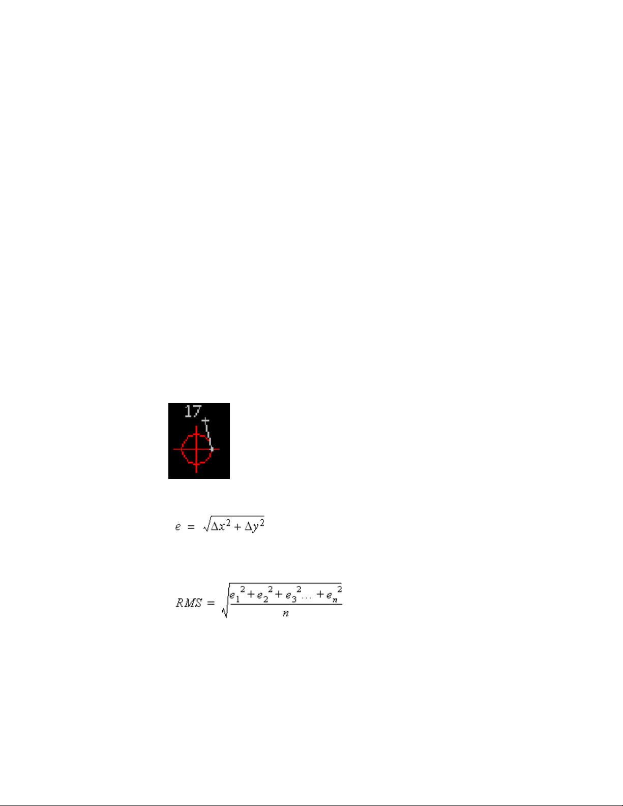
There are two transformation methods you can use to correct your image:
■ The Triangular method draws a series of triangles between the control
points, then applies the transformation to those areas. This process uses
the Delaunay triangulation method in which no point lies inside the circle
that includes the vertices of any triangle. Each triangular area is transformed
separately, so this method is much more accurate than the polynomial
method, but can result in the loss of some image data. The area to be
transformed, called the convex hull, is defined by the outermost destination
points. Image data outside the convex hull is discarded. You can see which
portion of the image will be transformed using the Preview. If you want
to preserve more of the image data, place control points near the extents
of the image.
■ The Polynomial method transforms the entire image to match, as nearly
as possible, the control points you specify. Unlike the triangular method,
however, the actual destination points are not always located at the
destination points you specified. The resulting positional error is expressed
as a numerical value in the Rubbersheet dialog box, and is displayed
graphically on the image after the control points have been entered. As
shown in the following figure, the error for each point is measured as a
distance from the intended destination point to the actual destination
point.
The error is calculated using the following distance formula:
The total RMS (Root Mean Square) error of the image is calculated using the
following formula:
32 | Chapter 2 Inserting and Correlating Images
Page 45

By adjusting the polynomial degree, you can increase the accuracy of the
matching points. However, reducing the error can create a higher degree of
warping in the image as it is transformed to match the control points.
Therefore, you should use the lowest possible polynomial degree that will still
give you an acceptable result. Higher polynomial degrees result in smaller
errors at the control points, but more warping at locations away from the
control points.
The following table lists the maximum polynomial degrees possible for ranges
of control points. For example, if you select 12 control points, the maximum
polynomial degree you can select is 3. When the minimum number of control
points is used for a particular polynomial degree, the reported errors at the
control points will be zero.
Number of Control Points
Maximum Polynomial Degrees
13-5
26-9
310-14
415-20
521-27
ProdNameShort does not limit the number of control points you can use.
The Preview tool allows you to see the extents of the transformed image before
you actually apply the changes. The convex hull of destination points is
displayed in red, while the convex hull of source points is shown in blue.
Using four points to rubbersheet (e.g., four corners of an image) usually results
in error at these points. In some applications, such as when rubbersheeted
images will be tiled, this error may be unacceptable. To eliminate this error,
you can change the polynomial equation so that a zero error condition results
from the use of four points rather than three points. This change is made in
the system registry. For complete instructions, go to the ProdNameShort
Support website (http://www.autodesk.com/rasterdesign-support) and search on
the term “4 point rubbersheet”.
Rubbersheeting an Image | 33
Page 46

NOTE Rubbersheeting is best suited for making minor transformations to an
image. For best results, start with a comprehensive and accurate network of survey
control points, then use match and scale before rubbersheeting to get the image
as close to the desired results as possible. It is also helpful to get a good spread of
the control points over the entire image. Where you don't have control points,
you can specify anchor points.
TIP If you prefer to use the command line to rubbersheet your images, type
-irsheet.
NOTE Use the match feature to get the image as close as possible to the desired
result before you begin rubbersheeting.
To rubbersheet an image
1 Click Image menu ➤ Correlate ➤ Rubbersheet.
2 Select the image to rubbersheet.
NOTE If there is only one image in the current drawing, that image is
automatically selected.
3 On the Rubbersheet dialog box, select a method: Triangular or Polynomial.
4 Choose one of the following rubbersheeting methods:
■ Manually add control points by picking directly from the image.
Follow steps 5 to 8.
■ Create a grid of destination points to which you can match source
points. Follow steps 9 to 15.
■ Import a list of saved control points by clicking the Import button
and choosing the .txt file from the Open dialog box.
NOTE When you click OK, Rubbersheet automatically saves the last control
points you enter to a file named LASTRS.txt in your Temp folder.
The Rubbersheet dialog box displays the exact coordinates of each source
point and destination point, and the amount of error (if any).
Pick control points
5 Click the Add Points button.
34 | Chapter 2 Inserting and Correlating Images
Page 47

The Rubbersheet dialog box disappears and ProdNameShort prompts you
to select the first source point. You must select at least three pairs of
source points and destination points.
6 Select the first source point for the first control point on the image.
NOTE You can select points on specific raster entities by using raster snaps.
7 Do one of the following:
■ Specify the destination point to which the source point should be
moved.
■ Type a to anchor the selected point where it is.
■ Type u to undo the point and select the point again.
NOTE If you are using AutoCAD Land Desktop, you can substitute COGO
points by typing .p, .g, or .n when ProdNameShort prompts you to enter
destination points. For more information, see Snapping to COGO Points
(page 82).
8 Select at least three more pairs of source and destination points, and then
press Enter to return to the Rubbersheet dialog box. Go to step 16.
9 Click the Grid Points button.
The Rubbersheet dialog box disappears and the Grid Parameters dialog
box appears.
10 In the Points section, choose how many rows and columns of points you
want to comprise the grid.
The total number of points in the grid is displayed at the bottom of the
Points section.
11 In the Grid section, enter the X and Y origins of the grid, or click the Pick
button to choose the grid origin directly from the drawing (pressing Enter
to return to the Grid Parameters dialog box).
12 In the Cell section, enter the X and Y sizes to determine the distance
between columns and rows (respectively), or click the Pick button to draw
a two-point rectangle representing the cell size directly in the drawing
(pressing Enter to return to the Grid Parameters dialog box).
13 Click the Preview button to see a representation of the grid in the drawing
(pressing Enter to return to the Grid Parameters dialog box).
Rubbersheeting an Image | 35
Page 48

14 Click the Add Points button to match source points to the grid of
destination points.
The Grid Parameters dialog box disappears and ProdNameShort
automatically pans to the first destination point.
NOTE You can select points on specific raster entities by using raster snaps.
15 Do one of the following:
■ Click to enter a corresponding source point for the current destination
point.
■ Type a to anchor the selected point where it is.
■ Type s to skip to the next destination point. ProdNameShort will
return to this point when the other destination points have been
matched to source points.
■ Type u to undo the point and select the point again.
ProdNameShort automatically pans to the next point until all of the
destination points have been matched to source points.
16 If you selected Polynomial as the transformation method, and you entered
six or more control points, you can adjust the polynomial Degree value.
This decreases error by increasing the degree to which an image can be
transformed in order to match control points.
NOTE It is a good idea to use the lowest possible polynomial degree that
will still give you an acceptable result. Higher polynomial degrees result in
smaller errors at the control points, but also result in more warping at places
where there are no control points.
17 If you want to view a specific point, select that point from the list of
control points, and then click the Zoom To button to view the point in
the drawing.
18 If you want to adjust a specific point, select that point from the list of
control points, and then click the Repick button to enter a new control
point.
NOTE Select the Auto Zoom check box if you want AutoCAD to zoom in to
the selected control point when you use Repick.
36 | Chapter 2 Inserting and Correlating Images
Page 49

19 If you want to remove a specific control point from the list, select that
point from the list of control points, and then click the Delete button.
20 Click the Preview button to see the extents of the transformed image
before you actually apply the changes. The convex hull of destination
points is displayed in red, while the convex hull of source points is shown
in blue. Press Enter to return to the Rubbersheet dialog box.
21 Click the Export button to save your control point set to a .txt file for
later use.
NOTE You can import the saved control points to rubbersheet other images,
such as superimposed images for the same drawing.
22 Click OK to perform the rubbersheet.
If you do not get the results you want, use the UNDO command and try
again. Use the match feature to get the image as close as possible to the
desired result. For more information, see Undoing Edits to an Image (page
81).
Quick Reference
Menu
Image ➤ Correlate ➤ Rubbersheet
Raster Design Toolbar
Command Line
irsheet
Dialog Box
Grid Parameters Dialog Box (page 315)
Rubbersheeting an Image | 37
Page 50

38
Page 51

Saving Images
3
Images are saved and managed separate from the drawings that contain them.
There are several ways to save images in Raster Design:
■ Click File ➤ Save/Save As. You are prompted to save each image that has changes, and
then you are prompted to save the drawing. You can click Save As to save the image with
a new name, location, or file format.
■ Click Image menu ➤ Save. This command saves an image without saving the drawing.
You can save more than one image at a time using this command.
■ Click Image menu ➤ Save As. This command saves an image to another file name, file
format, or location, without saving the drawing.
■ Click Image menu ➤ Capture. This command saves a displayed image or image set as a
standard AutoCAD image, for use with Raster Design or other programs.
■ Click Image menu ➤ Image Embed. This command saves a bitonal image within the host
drawing, making it easier to manage for transmission and storage.
■ Click Image ➤ Export ➤ Image.
This command saves an image to a different file format and allows you to save correlation
data separately in resource files and world files, for use with Raster Design or other
programs. For more information, see Correlation Output Types (page 54).
Export is the only way to save images displayed from digital elevation models (DEM) and
multispectral data.
Saving an Image
After you edit an image, you can save it without saving your drawing.
You can save more than one image at a time using this method. The image will
be saved using the current name and format.
39
Page 52

To save an image without saving your drawing
1 Click Image menu ➤ Save.
2 Select the image(s) you want to save.
NOTE You can also select the image first, and then right-click to display the
shortcut menu where you can select Image ➤ Write ➤ Save.
3 Press Enter to complete the selection set.
The image(s) you selected are saved.
If any of the images you select are unnamed, then the Save As dialog box
is displayed so you can give the image a name, location, and file type.
For more information, see Saving an Image to Another File Name, Type,
or Location (page 43).
If your image does not save correctly, verify the following
■ No copies of the image exist in other drawings.
■ The URL address you specified is correct.
■ The read-only attribute is not set on your disk.
NOTE Raster Design uses Single Image Optimization (page 396) to speed up the
editing commands.
Quick Reference
Menu
Image ➤ Save
Toolspace Shortcut Menu
Image Insertions view, image ➤ Write ➤ Save
Object Shortcut Menu
Image ➤ Write ➤ Save
Raster Design Toolbar
40 | Chapter 3 Saving Images
Page 53

Command Line
isave
Saving Images with AutoCAD Save
You can use the AutoCAD Save option to save the changes to your images.
The AutoCAD Save option is standard for most Autodesk products that use
Raster Design. When you save in this way, the correlation data for the images
is stored in the drawing. The next time you open the drawing, the images are
displayed.
NOTE You can use the AutoCAD UNDO command to undo each edit that you
make, back to the last time you saved your drawing. The information pertaining
to these edits is saved in a buffer file that can become quite large and reduce the
performance of your system. Saving your drawing and images clears this buffer.
To save an image using the AutoCAD Save command
1 Click File menu ➤ Save. Or exit AutoCAD.
You are prompted to save your drawing, and then you are prompted
separately for each image that has changed. The name of the image to
be saved is specified in the Save dialog box.
NOTE You are only prompted to save your image files if you have modified
image data. If you have changed only correlation information, then AutoCAD
saves the correlation information but does not prompt you to save your image
files.
2 Click one of the following:
■ Save save the specified image and be prompted for the next image.
This option saves the image using the same path, name, and format.
■ Save All saves all images with no further prompts.
■ Skip continues without saving the specified image and be prompted
for the next image.
■ Skip All continues without saving any more images.
■ Save As saves the specified image to another path, name, or file format.
■ Information displays information about the image before you save it.
Saving Images with AutoCAD Save | 41
Page 54

For certain file formats, such as TIFF, you are prompted for the
encoding and data organization methods you want to use. For more
information, see Encoding and Data Organization Methods (page 54).
Quick Reference
Menu
File ➤ Save
AutoCAD Toolbar
Dialog Box
Save As Dialog Box (page 366)
Embedding Images in a Drawing
You can save bitonal images within a drawing to simplify file management.
The regular Save operations save drawings and their associated images as
separate files, often in different directories. This structure can be difficult to
manage if you need to transfer drawings and images to other locations and
retain the file relationships. Image embedding (iembed command) provides
an alternative for bitonal images by saving them within the host drawing.
An embedded image can be removed from its host drawing and saved as an
separate file by using the Un-embed (iunembed) or Save As (isaveas) commands.
To save an image using the Image Embed command
1 In the drawing window, select the image or images you want to embed.
2 Click Image menu ➤ Image Embed.
3 Verify that the images are embedded in the drawing.
In Image Manager, “_EMBED” is added to the end of the image name for
each embedded image. If you need to open Image Manager, click Image
menu ➤ Manage.
42 | Chapter 3 Saving Images
Page 55

To un-embed an image
1 In Image Manager, select the image you want to un-embed.
2 Right-click and click Un-embed.
3 In the Save As dialog box, specify the name, location, and format for the
image.
Quick Reference
Menu
Image ➤ Image Embed
Command Line
iembed, iunembed
Image Manager
Right-click image ➤ Embed or Un-embed
Dialog Box
Save As
Saving an Image to Another File Name, Type, or Location
You can save an image to another file name, file type, or location, without
saving the drawing file.
For example, if you have edited an image and you do not want to modify the
original image file, then you can save the edited image to a different file name.
If you have access to an FTP site, you can save your images to the Internet.
For more information, see Saving an Image to an FTP Site (page 45).
The Save As option is also useful if you inserted a non-editable image file that
you want to edit. This situation may occur if you inserted an image from a
CD-ROM, for example, or if you inserted an image that has a file format that
Raster Design cannot write to.
NOTE Raster Design uses Single Image Optimization (page 396) to speed up the
editing commands.
Saving an Image to Another File Name, Type, or Location | 43
Page 56

To save an image to a different file name, file type, or location
1 Click Image menu ➤ Save As.
2 Select the image to save. You can save only one image at a time using
this command.
The Save As (page 366) dialog box is displayed.
NOTE You can also select the image first, and then right-click to display the
shortcut menu where you can select Image ➤ Write ➤ Save As.
3 You can enter a different file name in the File Name box.
4 There are two methods you can use to navigate to a new location to which
to save the image:
■ Choose the drive and folder using standard Windows navigation
procedures.
■ Choose a location from the Places List on the left side of the dialog
box to navigate directly to the My Documents folder (or the Personal
folder, depending on which operating system you are using), the
Desktop, or the Favorites folder.
5 You can save the image to a different file type by selecting a file type
from the Save File as Type list.
NOTE AutoCAD works best with certain image types. To optimize
performance, export or save your images as tiled, compressed TIFFs whenever
possible.
6 Click OK when you are ready to save the image.
For certain file formats, such as TIFF, you are prompted for the encoding
and data organization methods you want to use. For more information,
see Encoding and Data Organization Methods (page 54)
NOTE If you have saved using the save as command, multiple copies of the
image now exist, but all copies point to the new filename. For more
information, see Save As Dialog Box (page 366).
44 | Chapter 3 Saving Images
Page 57

Quick Reference
Menu
Image ➤ Save As
Toolspace Shortcut Menu
Image ➤ Write ➤ Save As
Object Shortcut Menu
Image ➤ Write ➤ Save As
REM Toolbar
Command Line
isaveas
Dialog Box
Save As Dialog Box (page 366)
Saving an Image to an FTP Site
If you have access to an FTP site, you can save your images to the Internet.
To save an image to an FTP site
1 Click Image menu ➤ Save As.
2 Select the image to save. You can only save one image at a time using
this command.
The Save As (page 366) dialog box is displayed.
3 Click the FTP icon in the Places List.
4 Click Tools menu ➤ Add/Modify FTP Locations.
The Post to FTP Locations dialog box is displayed.
5 In the Name of FTP Site text box, enter the name of the FTP server.
6 In the Log On As section, select either Anonymous or User.
If you select the User option, enter a username in the combo box.
Saving an Image to an FTP Site | 45
Page 58

7 Enter a password in the Password text box.
8 Click Add.
9 Click OK to return to the Save As dialog box.
10 Navigate the FTP site using standard Windows navigation methods.
11 You can enter a different file name in the File Name box.
12 You can save the image to a different file type by selecting a file type
from the Save File as Type list.
13 Click OK when you are ready to save the image.
For certain file formats, such as TIFF, you are prompted for the encoding
and data organization methods you want to use. For more information,
see Encoding and Data Organization Methods (page 54)
NOTE If you have saved using the save as command, multiple copies of the
image now exist, but all copies point to the new filename. For more
information, see Save As Dialog Box (page 366).
Quick Reference
Menu
Image ➤ Save As
Toolspace Shortcut Menu
Image Insertions view, Insertion object ➤ Write ➤ Save As
Object Shortcut Menu
Image ➤ Write ➤ Save As
Raster Design Toolbar
Command Line
isaveas
Dialog Box
Save As Dialog Box (page 366)
46 | Chapter 3 Saving Images
Page 59

Capturing an Image
You can capture an image if it cannot be saved in the usual way, or if you
want to preserve a specific display for later use.
An image capture is like a photograph of the displayed image on your screen.
It is particularly useful when you want to prepare images for a presentation
or a report. For example, you can capture several displays of satellite data with
different color maps. Then you can edit these static images with regular
Autodesk tools, and save them in a simpler format such as JPEG or TIFF.
The transparency setting in the source image is preserved in the capture. For
complex images from digital elevation models (DEM) or multispectral data,
the capture is simplified to a true color image with an Image Adjust color map.
The transparency setting in the source image is preserved in the capture.
When used with AutoCAD Map 3D, Raster Design can capture data from a
layer in Display Manager, which can include Feature Data Objects (FDO) and
other imported data. In this type of capture, you have several options for the
capture, such as capturing the stylized display or the source data, selecting
the capture area, resolution, and type of coordinate transformation, if
applicable.
To capture an image
1 Click Image menu ➤ Capture.
If you are using AutoCAD Map 3D and capturing a raster layer, the Display
Manager Raster Layer Capture Dialog Box (page 307) is displayed for you
to specify capture parameters such as the data type, area, resolution, and
type of coordinate transformation.
The current image is captured and inserted into the display, directly on
top of the source image. The capture is also added to the top of the Image
Manager tree.
2 If you want to save the capture with a different name, format, or location,
select the capture, right-click and click Image menu ➤ Write ➤ Save As.
Quick Reference
Menu
Image ➤ Capture
Capturing an Image | 47
Page 60

Command Line
icapture
Toolspace Shortcut Menu
Image Insertions view, Insertion object ➤ Capture
Object Shortcut Menu
Image ➤ Capture
Raster Design Toolbar
Command Line
icapture
Exporting Images
Use Export commands to save an image to a different file format or to save
correlation files for the image.
Exporting is the only way to save images displayed from digital elevation
models (DEM) and multispectral data. These images are saved in GeoTIFF
format.
Use the options in the Export Options (page 313) dialog box to handle image
correlation data and rotation values, if applicable.
NOTE If you want to save an image to another file format, name, or location,
without saving correlation information, then do not select a correlation output
type, or use the Save As option instead. For more information, see Save As Dialog
Box (page 366).
Correlation files store insertion point, scale (page 396), rotation angle (page 395),
and density (page 387) information for the image. GeoTIFF files can also include
coordinate system data. Depending on the file format you select, you can save
the correlation information to a resource file (page 395), a world file (page 400),
or to the image file. Normally, these files are saved to the same location as
the image file. However, you can control this path on the Paths tab (page 355)
of the Raster Design options dialog box. For more information, see Correlation
Search Paths (page 247).
48 | Chapter 3 Saving Images
Page 61

Correlation files store insertion point, scale (page 396), rotation angle (page 395),
and density (page 387) information for the image. Depending on the file format
you select, you can save the correlation information to a resource file (page
395), a world file (page 400), or to the image file. Normally, these files are saved
to the same location as the image file. However, you can control this path on
the Paths tab (page 355) of the Raster Design options dialog box. For more
information, see Correlation Search Paths (page 247).
If you want to export correlation as a world file without exporting the
associated image, you can use the iworldout command.
NOTE Raster Design uses Single Image Optimization (page 396) to speed up the
editing commands.
For certain file formats, such as TIFF, you are prompted for the encoding and
data organization methods you want to use. For more information, see
Encoding and Data Organization Methods (page 54).
Exporting an Image
You can export images in order to save them to new locations, file names, or
file types.
You can also save image correlation data as a separate file.
To export an image
1 Click Image menu ➤ Export ➤ Image.
2 Click the frame of the image you want to export.
The Export (page 311) dialog box is displayed.
3 In the Files Of Type box, select the desired format for the new image.
If you are exporting a DEM or multispectral image the type must be
GeoTIFF.
NOTE AutoCAD works best with certain image types. To optimize
performance, export or save your images in tiled compressed TIFF format
whenever possible.
4 Optionally, to navigate to a new location to which to export the image,
do one of the following:
■ Select the drive and folder using standard Windows navigation
procedures.
Exporting an Image | 49
Page 62

■ Select a location from the Places List on the left side of the dialog box
to navigate directly to the My Documents folder (or the Personal
folder, depending on which operating system you are using), the
Desktop, or the Favorites folder.
5 In either the File Name or Base Name box, enter a name for the image
file or select a file name from the list.
NOTE You cannot export an image to a file name that is locked. For example,
if one person loads image1.tif and locks the raster image file, then another
person can not export image2.tif to image1.tif because the first person has
a raster file lock for image1.tif. For more information about locking image
files, see Locking Method for Image Files (page 258).
6 Click Export.
7 In the Encoding Method (page 311) dialog box, specify whether to
compress the image, and if so, which encoding method to use. Click
Next.
8 In the Data Organization (page 307) dialog box, specify Tiled, Stripped,
or Monolithic. Click Next.
9 In the Export Options (page 313) dialog box, specify the relationship
between the exported image and the drawing. Specify how to handle
image rotation, if applicable, and correlation data.
10 Do one of the following:
■ If a Finish button is displayed at the bottom of the screen, click the
button to export the image.
■ If a Next button is displayed at the bottom of the screen, click the
button to open the Coordinate System Assignment (page 305) dialog
box, where you can select a GeoTIFF coordinate system for the
exported image.
Quick Reference
Menu
Image ➤ Export ➤ Image
50 | Chapter 3 Saving Images
Page 63

Toolspace Shortcut Menu
Image Insertions view, Insertion object ➤ Write ➤ Export
Raster Design Toolbar
Command Line
iexport
Dialog Box
Export Dialog Box (page 311)
Exporting an Image to an FTP Site
If you have access to an FTP site, you can export your images to the Internet.
To export an image to an FTP site
1 Click Image ➤ Export ➤ Image.
2 Select the image to export. You can export only one image at a time using
this command.
NOTE You can also select the image first, and then right-click to display the
shortcut menu where you can select Image ➤ Write ➤ Export.
3 In the Export Data (page 311) dialog box, click the FTP icon in the Places
List.
4 Click Tools menu ➤ Add/Modify FTP Locations.
The Post To FTP Locations dialog box is displayed.
5 In the Name Of FTP Site text box, enter the name of the FTP server.
6 In the Log On As section, select either Anonymous or User.
If you select the User option, enter a username in the combo box.
7 Enter a password in the Password text box.
8 Click Add.
9 Click OK to return to the Export dialog box.
Exporting an Image to an FTP Site | 51
Page 64

10 Navigate the FTP site using standard Windows navigation methods.
11 You can enter a different file name in the File Name box.
12 You can export the image to a different file type by selecting a file type
from the Save File as Type list.
13 Click OK when you are ready to export the image.
For certain file formats, such as TIFF, you are prompted for the encoding
and data organization methods you want to use. For more information,
see Encoding and Data Organization Methods (page 54).
NOTE If you have saved using the Save As option, multiple copies of the
image now exist, but all copies point to the new filename. For more
information, see Save As Dialog Box (page 366).
Quick Reference
Menu
Image ➤ Export ➤ Image
Toolspace Shortcut Menu
Image Insertions view, Insertion object ➤ Write ➤ Export
REM Toolbar
Command Line
iexport
Dialog Box
Export Dialog Box (page 311)
Exporting a World File
You can export the image correlation without exporting the entire image by
using the iworldout command to create a world file (page 400).
52 | Chapter 3 Saving Images
Page 65

The resulting world file shares the same file name as the associated image, but
the extension ends in a “w” (for example, the world file for lakshor.tif is
lakshor.tfw).
NOTE Raster Design exports world files based on World coordinates and imports
them based on the current UCS.
To export a World File
1 Click Image menu ➤ Export ➤ World File.
2 Type a path to which to save the file, or press Enter to accept the default
path.
NOTE By default this command saves the world file to the same location as the
image file. However, you can control this path on the Paths tab of the Raster Design
Options dialog box. For more information, see Correlation Search Paths (page
247).
Quick Reference
Menu
Image ➤ Export ➤ World File
Toolspace Shortcut Menu
Image Insertions view, Insertion object ➤ Write ➤ Export
Raster Design Toolbar
Command Line
iexport
Dialog Box
Export Dialog Box (page 311)
Exporting a World File | 53
Page 66

Correlation Output Types
Depending on what type of image you are exporting, you can choose from
among some of the following correlation output file types:
■ Bitonal Images. Use to creates resource files compatible with Raster Design
ESP version 7 (or higher).
■ Color or Grayscale Images. Use to creates resource files compatible with
Raster Design 7.5 (or higher). You can save the correlation data externally,
rather than in the drawing, so that you can use the same correlation data
in another drawing.
■ World File. Use if you need to transfer the image to another program that
can use a world file (page 400), such as a mapping program. You can use the
iworldout command to export a world file without exporting the associated
image.
■ Resource File. Use to share images with other Raster Design users, or for
inserting the image into another drawing. A resource file has a .RES
extension. You can create resource files for all image types.
■ Image File. Use with file types that can store correlation information within
the image file. Image File is also a correlation output type option when
you are saving an RLC image.
■ GeoTIFF. Use with TIFF files to store correlation information within the
image file.
NOTE Both Resource files and World files are saved to the path specified in the
Raster Design Options dialog box. If no correlation search path is designated,
Raster Design uses the folder where the image file is stored. For more information,
see Correlation Search Paths (page 247).
Encoding and Data Organization Methods
When you export certain file formats, such as TIFF, you are prompted for the
encoding and data organization methods you want to use. If you are uncertain
about which method to choose, then accept the default, which reflects how
the image was saved previously.
NOTE AutoCAD works best with certain image types. To optimize performance,
export or save your images in tiled compressed TIFF format whenever possible.
54 | Chapter 3 Saving Images
Page 67

To choose a method of data encoding (compression) and data organization
1 In the Encoding Method dialog box, choose an encoding method to
reduce the image file size. If file size is not an issue, then select the
Uncompressed option.
NOTE If you are unsure which method to choose, then accept the default,
which reflects how the image was saved previously.
2 Click Next to display the Data Organization dialog box. The data
organization method affects how your image data is stored, regardless of
the encoding method. Choose one of the following methods:
■ Monolithic stores all image data together (not recommended for large
images).
■ Stripped stores the image data in strips.
■ Tiled stores the image data in tiles.
3 Click Finish to complete the process, or click Back to return to the
Encoding Method page.
Encoding and Data Organization Methods | 55
Page 68

56
Page 69

Changing Image Properties
You can use the AutoCAD Properties window to specify image properties.
AutoCAD Properties
In the AutoCAD Properties window, you can specify image properties.
The properties are as follows:
■ Layer
■ Color
■ Linetype
■ Display options, including image transparency, visibility, brightness, contrast,
and fade values
■ Geometry settings, such as X, Y, and Z position, rotation, width, height, and
scale
4
When an image mask is selected, you can turn the mask on or off, turn image
frames on or off, and set properties of the images outside the mask.
You can also use the Properties window to obtain the following information
about the image:
■ Name
■ Path (saved path)
■ File type and size
■ Dates when the image was created and last modified
■ Color depth and type
57
Page 70

■ Pixel width and height
■ Edit status
If the image contains raster entity manipulation (REM) objects, you can use
the Properties window to see detailed specifications of these objects.
Image Display Properties
You can choose to hide or display images in your drawing to improve the
system redraw time.
You can also hide/show and unload/reload images from the Image Manager
Toolspace (page 330).
To change image display properties
1 Click the frame of the image(s) you want to change, then
right-click ➤ Properties.
TIP If you are zoomed in and cannot see the image frames, press Shift +
left-click to select the image(s).
2 Click the Show Image property, then select Yes or No from the list.
3 Click the Show Clipped property, then select Yes or No from the list.
4 Close the Properties dialog box.
For more information on the Properties window, see the AutoCAD
Command Reference in the AutoCAD Help or Users Guide.
Image Display Quality
You can display your images in high quality or draft quality.
High quality involves dithering the pixels so that the transitions between pixels
appear more gradual. Draft quality can speed up the performance of your
system, but may reduce the quality of some color and grayscale images on
screen.
To change the image display quality
1 Select an Image, then right-click ➤ Properties.
58 | Chapter 4 Changing Image Properties
Page 71

2 Click the Quality Setting property, then select a new setting from the list:
■ High dithers the pixels. Color and shade differences between pixels
are blended for a more realistic appearance.
■ Draft does not dither the pixels. This setting is recommended for
bitonal images, or whenever you want to see the pixel size.
NOTE The display quality setting affects only how the image is displayed
on screen. It does not alter in any way the contents of the image file.
3 Close the Properties dialog box.
Image Frame Display
You can choose to display the image frame (page 391) above the images, behind
the images, or you can turn off the frames.
When frames are behind the images, you can still select an image by selecting
the frame. However, when you turn frames off, you cannot select an image
frame.
To change how image frames are displayed
1 Click the frame of the image(s) you want to change, then
right-click ➤ Properties.
NOTE If you are zoomed in and cannot see the image frames, press Shift +
left-click to select the image(s).
2 Click the Frame Setting property, then select a setting from the list:
■ Frame above displays the frame above the image.
■ Frame below hides the frame behind the image, but you can still select
the image by selecting the frame.
■ Frames off turns off the frames. If frames are turned off, you must use
the Shift + left-click select method to select an image.
NOTE If you use the Toggle Frames option to turn the frames off and
then turn them on again, the frames reappear above the image. For more
information, see Changing the Image Frame Visibility (page 242).
Image Frame Display | 59
Page 72

3 Close the Properties dialog box.
Image Layer
When you insert an image, it is inserted onto the current AutoCAD layer.
However, you can move the image to another layer. The following layer
properties allow you to control image display, image editing, and image saving.
ties
FunctionLayer Proper-
On/Off
Thaw/Freeze
Unlocked/Locked
Color
Turns images on and off. Images that are off are still regenerated.
When a layer is off, you can save an image to the layer, but
you cannot edit an image on that layer.
Saves the image. You cannot display or edit an image on
a frozen layer. The system does not update a frozen layer.
Displays and saves an image on a locked layer. You cannot
edit a locked layer.
A bitonal image can use the color of the layer. For more
information, see Foreground Color of a Bitonal Image (page
61).
TIP If you have multiple images on top of each other, and you do not want to
rub, crop, or mask all of the images, you can lock a layer containing an image you
do not want modified.
To move an image to a different layer
1 Click the frame of the image(s) you want to move to a different layer,
then right-click ➤ Properties.
TIP If you are zoomed in and cannot see the image frames, press Shift +
left-click to select the image(s).
2 Click the Layer property, then select a new layer from the list.
3 Close the Properties dialog box.
60 | Chapter 4 Changing Image Properties
Page 73

For more information on the Properties window, see the AutoCAD Command
Reference in the AutoCAD Help or Users Guide.
Linetype of an Image Frame
You can select a different AutoCAD linetype for an image frame.
To change the linetype of an image frame
1 Click the frame of the image(s) whose linetype you want to change, then
right-click ➤ Properties.
2 Click the Linetype property, then select a new linetype from the list.
3 Close the Properties dialog box.
For more information on the Properties window, see the AutoCAD
Command Reference in the AutoCAD Help or Users Guide.
Foreground Color of a Bitonal Image
The foreground color is used for the raster entities in a bitonal image.
The foreground color is also known as the color map of a bitonal image. It
can be changed from the Image Manager toolspace, just like color maps for
other image types.
You can select a color for the image from the current palette or have the image
use the color of the AutoCAD layer it is on.
To change the foreground color of a bitonal image
1 Click the frame of the bitonal image(s) you want to change.
TIP If you are zoomed in and cannot see the image frames, press Shift +
left-click to select the image(s).
2 Right-click, then choose Properties from the short-cut menu.
3 Click the Color property, then select a new color from the drop-down
list.
4 Close the Properties dialog box.
For more information on the Properties window, see the AutoCAD
Command Reference in the AutoCAD Help or Users Guide.
Linetype of an Image Frame | 61
Page 74

Quick Reference
Toolspace Shortcut Menu
From color map object ➤ Edit Color Map
Object Shortcut Menu
Properties, Color
Command Line
properties
Transparency Color of an Image
You can make one color in each image transparent.
Making a color transparent is helpful if you want to see information that is
displayed behind the image. In a bitonal image, the transparency color is
always the background color of the image. For grayscale and color images,
you can choose the transparency color.
The transparency color is also used to replace data that is removed when you
edit an image using the rub or crop commands. If transparency is turned on
for the image, the rubbed areas (or the slack space in a cropped image) become
transparent. For more information, see Cropping Images (page 144) and
Removing (Rubbing) Images (page 149).
If you merge two images, the transparency color that is used to fill the space
between the two images depends upon the display order you specify in the
Image Manager Toolspace (page 330).To use the transparency color of the first
image in the list for the fill color, click Image menu ➤ Merge ➤ Images.
Sometimes you may want to designate an unused color as the transparency
color. For instance, when merging images, turning on transparency may make
some desirable pixels transparent. The rbackground command allows you to
designate an unused color in a grayscale image as the transparency color.
Pixels with a value of 255 (white) are changed to a value of 254 (near white),
then the transparency color is set to a value of 255. The resulting image will
have no pixels with a value of 255.
NOTE Changing the transparency color does not affect the color of the existing
rubs and crops.
62 | Chapter 4 Changing Image Properties
Page 75

To change the transparency color
1 Zoom in on the image so you can accurately select the color.
2 Select the image, then right-click ➤ Properties.
NOTE If you are zoomed so you cannot see the image frames, press Shift +
left-click to select the image.
3 Click the Transparency Color property, then click the button in the
property field.
The Transparency Color dialog box is displayed.
NOTE Selecting a color is necessary only for color and grayscale images. To
make a bitonal image transparent, skip to step 7.
4 Click Select.
The cursor changes shape and the dialog box temporarily disappears so
that you can choose a color from the image.
5 Pick the desired color on the image, and click OK.
6 Click the Transparency property, then select Yes from the list to make
the color you just selected transparent.
If you want to use the color for rubbing and cropping but you also want
the color displayed in the image, select No for Transparency.
NOTE Changing the transparency color does not affect the color of the
existing rubs and crops.
7 Close the Properties dialog box.
Unused Color for Transparent Color
The rbackground command allows you to designate an unused color as the
transparency color.
This is especially useful for merging images in which the designated
transparency color in one image may cause valuable pixels in the other image
to become transparent.
Unused Color for Transparent Color | 63
Page 76

To designate an unused color as the transparency color
1 On the command line, enter rbackground.
2 Select the image or images that you want to change, and then press Enter.
NOTE You can also select your image or images before you use the
rbackground command.
64 | Chapter 4 Changing Image Properties
Page 77

Managing Images and Insertions
Each instance of an image that you insert into a drawing is called an insertion. Each insertion
is based on an image data definition. Changing the attributes of an insertion does not affect
the image data definition.
The Raster Design Image Manager (page 330) provides two views of the image data in a drawing:
■ The Image Insertions (page 331) view focuses mainly on the screen display; the object tree
shows only image insertions and color maps.
■ The Image Data (page 332) view is more detailed, showing the data elements associated
with an image.
Each view provides different shortcut menus for object types, and an item view that shows
properties of the insertions and data in tabular form. In the Image Insertions view, a button
at the top of the toolspace toggles between the item view and the image preview.
5
Controlling the Image Manager Toolspace
You should understand several controls to make the Image Manager work best
for you.
For more information on the toolspace controls, see Image Manager (page 330).
Modifying the Item View Layout
For some image data, you can choose which columns to display and change
the order of columns in the table.
The Image Manager item view is editable for object types such as the drawing,
where the data display is a table of three or more columns. This format is more
65
Page 78

common in the Image Data view than in the Image Insertions view. Some
object types, such as the color map show a two-column item view (Properties
and Value) that is not editable.
To modify the layout of the Item View table
1 To display the Image Manager (page 330) toolspace, click Image ➤
Manage..
2 Choose either the Image Insertions or Image Data view, then click the
drawing name at the top of the tree.
3 In the tabular item view, click a column-head and drag it left or right in
the list to change the order of the columns.
4 Right-click a column head to see a menu where you can show or hide
columns in the table.
Displayed column headings are checked. If you want to remove a column
from the display, clear the check mark for the column name.
5 Click a column head to sort the information in the table by that column.
6 Click and drag the edge of the dialog box to resize it.
NOTE You can also change the width of the columns. Just click on the line
between column headings and drag it left or right. When you click Close,
your changes to the column widths are saved and used the next time you
open the dialog box.
Copying Information to the Clipboard
You can transfer reference information about raster insertions or images to
other applications.
Both views of the Image Manager toolspace display data about the images in
the drawing. Where this data is displayed in a table of three or more columns,
you can transfer the data to other applications by copying the contents of
one or more selected rows to the Clipboard, then pasting it into the other
application window.
To copy item view data to the Clipboard
1 To display the Image Manager (page 330) toolspace, click Image ➤
Manage.
66 | Chapter 5 Managing Images and Insertions
Page 79

2 Choose the row(s) you want to copy from the toolspace item view.
3 Right-click and click Copy to Clipboard.
4 Click Close.
Managing Image Display and Data
You can arrange the images within a drawing, removing or restoring them,
and changing their saved location.
Multiple insertions of an image can show different views of the data.
This is especially useful with multispectral and digital elevation model (DEM)
data. For example, you could have one DEM insertion with a color map that
shows elevation bands and another insertion that shows ground slopes.
The Image Insertions (page 331) view of the Image Manager toolspace is
especially useful for zooming to an image, changing image display order, and
editing color maps. You can change the attributes of an insertion, without
affecting the image source data.
The Image Data (page 332) view is useful for creating new image insertions and
managing the image data in your drawing.
See also:
■ Embedding Images in a Drawing (page 42)
Zooming to an Image
You can use the Image Manager toolspace to zoom to the extents of one or
more insertions.
If you can see the frame of an image, you can also zoom to it by right-clicking
the frame and selecting Image ➤ Zoom To. This is especially useful if you are
zoomed in close and want to zoom out to see the complete image.
To zoom to an image
1 To display the Image Manager (page 330) toolspace, click Image ➤
Manage..
2 Click the Image Insertions (page 331) view.
Managing Image Display and Data | 67
Page 80

3 Click the name of the insertion or insertions you want to see, then
right-click and click Zoom To.
Quick Reference
Toolspace Shortcut Menu
Image Insertions view: right-click image name ➤ Zoom To
Object Shortcut Menu
Right-click image frame ➤ Image ➤ Zoom To
Changing the Color Map of an Image
You can change the color map to modify the appearance and the type of data
displayed in the image.
The complexity of this procedure varies with color map type, as detailed in
the following table.
Color Map Editing ProcessColor Map Type
Bitonal
Image Adjust
Palette
Band Assignment
Use AutoCAD Select Color dialog to choose foreground
color
Use AutoCAD Image Adjust dialog to set image brightness,
contrast, and fade levels
Use Palette Assignment Color Map (page 345) dialog to
choose or edit a palette color map
Use Band Assignment Color Map (page 301) dialog to assign
image bands to color channels
NOTE To remove all unused color maps from a drawing, type ipurgecm at the
command line.
See also:
■ Adding a Visual Elevation Key to a DEM Image (page 69)
■ Creating Another Insertion of an Image (page 70)
68 | Chapter 5 Managing Images and Insertions
Page 81

■ Adjusting Images with the Histogram (page 92)
To change the color map of an image
1 To display the Image Manager (page 330) toolspace, click Image ➤
Manage..
2 Click the Image Insertions (page 331) view.
3 Click the image insertion for which you want to change the color map,
right-click and click Edit Color Map. Depending on image type, the
applicable dialog box opens.
NOTE If you edit an existing palette color map that is used by several images
in the drawing, the changes will affect all of the images. To affect only one
image, you can assign the color map that is closest to what you want, then
copy that color map and rename it.
4 Make changes as required.
Adding a Visual Elevation Key to a DEM Image
You can add a small image that displays how colors are mapped to elevation
ranges from lowest to highest on a digital elevation model.
Sample elevation key
To make the elevation key more useful, add elevation values to the color
bands.
See also:
■ Changing the Color Map of an Image (page 68)
Adding a Visual Elevation Key to a DEM Image | 69
Page 82

To add a visual elevation key
1 Click Image menu ➤ Insert. Navigate to Raster Design\Samples, and
insert the image elev_small.dem into your current drawing.
2 In the Image Manager toolspace, expand the object tree under the image
elev_small, right-click the color map, and click Edit Color Map.
3 In the Palette Assignment Color Map dialog, select the color map that is
used in your primary image.
4 Adjust the size and location of the elevation key in relation to the primary
DEM image.
Creating Another Insertion of an Image
You can insert another copy of an image when you want to use a different
type of color map or make other display changes.
When you create another insertion of an AutoCAD image object (bitonal,
grayscale, index color or true color), you use the same type of color map,
which you can edit later.
Some of the custom image types that Raster Design handles can use two or
three different types of color maps, and the only place where these options
are presented is on the Image Data (page 332) view of the Image Manager
toolspace, when you right-click the image data definition. If you right-click
an existing color map, you can create a new image insertion using the same
color map type.
When the image data definition is in single-band integer format, such as
IKONOS 16-bit, a new insertion can use either a grayscale or palette color
map.
When the image data definition is multispectral, a new insertion can use a
grayscale, palette color, or false color map.
To create another insertion of an image
1 To display the Image Manager (page 330) toolspace, click Image ➤
Manage..
2 Right-click the image data definition for which you want a new
insertion and click New Insertion.
70 | Chapter 5 Managing Images and Insertions
Page 83

If the image is of single-band integer or multiband multispectral format, you
see a submenu with two or three color band types to choose from. As shown
in the following table, some of these choices invoke another dialog box where
you configure the color map to your needs.
Dialog BoxColor Map TypeImage Data Type
The new insertion is added to the drawing.
Displaying Point Data
Interactively display the cursor location and data about the image pixel at
that location.
The Raster Data Query (page 350)dialog box always tracks the cursor location
and displays the color values of the image pixel at that location. Other data
values associated with the pixel are displayed, subject to image type.
For example, if the image is displayed from a digital elevation model (DEM)
with a color map that interprets elevation values, the elevation of the pixel
at the cursor location is displayed. If Raster Design is running on Autodesk
Map, the working coordinate system is also displayed.
Palette colorSingle-band integer
GrayscaleMultiband Multispectral
Palette color
False color
Palette Assignment Color
Map Dialog Box (page
345)
Assign Multispectral Band
Dialog Box (page 301)
New Palette Color Insertion Dialog Box (page 344)
Band Assignment Color
Map Dialog Box (page
301)
To query pixel data in an image
1 Click Image menu ➤ Raster Data Query. The Raster Data Query dialog
box is displayed.
2 Optionally, resize the dialog box or dock it in the left pane.
Displaying Point Data | 71
Page 84

Quick Reference
Image Menu
Image ➤ Raster Data Query
Raster Design Toolbar
Dialog Box
Raster Data Query Dialog Box (page 350)
Showing and Hiding Images
You can use the Image Insertions view of the Image Manager toolspace to
show or hide an image.
The Hide operation causes the least change to an displayed image, as compared
to unload (page 400), erase (page 389), or detach (page 387). A hidden image is
removed from the display, but the frame remains visible and the image data
remains in the toolspace tree.
Use Show to restore a hidden image to the display. If an image has been
unloaded, a show operation reloads it.
To show or hide an image
1 To display the Image Manager (page 330) toolspace, click Image ➤
Manage..
2 Click the Image Insertions (page 331) view.
3 Click the insertion whose display status you want to change, then do
one of the following:
■ If the image is hidden, right-click and click Show.
■ If the image is displayed, right-click and click Hide.
Quick Reference
Toolspace Shortcut Menu
Image Insertions view: right-click insertion ➤ Hide/Show
72 | Chapter 5 Managing Images and Insertions
Page 85

Object Shortcut Menu
Click image frame, right-click Image ➤ Hide/Show
Command Line
ihideimage, ishowimage
Dialog Box
Image Insertions View (Image Manager Toolspace) (page 331)
Changing the Display Order of Images
You can change the order in which images are stacked for display in the
drawing.
The Image Insertions (page 331) view of the Image Manager toolspace shows
the display order of inserted images. Insertions at the top of the tree are at the
top of the display order. New image insertions are placed at the top of the
tree, but you can manually move them.
Display order is especially important if you want to layer a transparent bitonal
image directly above another image.
NOTE When you perform an editing command on an image, the display order
changes so that the image you modified is displayed on top of the other images.
To correct this, type REGEN on the command line. You do not need to change
the image order using the method described here. For more information, see
Correcting Image Display Order using REGEN (page 273).
To change the order in which your images are displayed
1 To display the Image Manager (page 330) toolspace, click Image ➤
Manage..
2 Select the Image Insertions (page 331) view.
3 Click the insertion you want to move, then right-click and select the type
of move: Move Forward, Move Back, Bring to Front, Send to Back.
NOTE You can also click and drag the insertion object up or down in the tree.
The insertion at the top of the tree is at the top of the display order.
Changing the Display Order of Images | 73
Page 86

Erasing an Image
You can erase an image from the AutoCAD drawing when you no longer need
it.
When you erase (page 389) an image, you can also detach (page 387) it, subject
to the Image Detach Options set on the User Preferences Tab
(ProductNameShort Options Dialog Box) (page 358). If you want to simply
remove the image from the display, without having to reconstruct it later,
consider using the hide (page 390) or unload (page 400) operations.
To erase an image
1 To display the Image Manager (page 330) toolspace, click Image ➤
Manage..
2 Click the Image Insertions (page 331) view.
3 Click the insertion you want to erase, right-click and click Erase.
If no more insertions from this image data definition remain in your
drawing, you may be asked if you want to detach the image. Detaching
removes the image data definition from the drawing.
NOTE If you want to restore the images, click Edit ➤ Undo.
Detaching an Image
Use the Detach operation to completely remove from a drawing an image
data definition and all its insertions.
The detach (page 387) operation is the most complete image removal method.
If you want to simply remove the image from the display, without having to
insert it later, consider using the hide (page 390) or unload (page 400) operations.
To detach an image
1 To display the Image Manager (page 330) toolspace, click Image ➤
Manage..
2 Click the Image Data (page 332) view.
3 Click the image data definition you want to detach, then right-click
and click Detach.
74 | Chapter 5 Managing Images and Insertions
Page 87

Unloading/Reloading an Image
Unloading an image removes the image data from working memory without
erasing the image objects from the drawing.
To improve application performance, you can unload images you no longer
need. An unloaded image cannot be displayed or plotted. The unload (page
400) operation is just one of several image removal methods. For temporary
removal, consider the hide (page 390) operation. For more complete removal,
consider the erase (page 389) and detach (page 387) operations.
Reloading puts the image back into working memory and redisplays it.
To unload or reload an image
1 To display the Image Manager (page 330) toolspace, click Image ➤
Manage..
2 Select the Image Data (page 332) view.
3 Click the data definition for the image you want to change, then do one
of the following:
■ If the image is loaded, right-click and click Unload.
■ If the image is unloaded, right-click and click Reload.
Changing the Active Path
The active path is the current location of the inserted image file.
Compare the definitions for active path (page 381) and saved path (page 396).
The current active path is visible in the list view of Image Manager when you
select the image. This is also where any changes to the image are saved if you
click Image ➤ Save..
If you want to edit an image without changing the original version, you should
save a copy in a different location and file format. To do this, click Image
menu ➤ Save As. Doing this also directs the active path to the copy. For more
information,see Saving an Image to Another File Name, Type, or Location
(page 43).
To change the active path
1 To display the Image Manager (page 330) toolspace, click Image ➤
Manage..
Unloading/Reloading an Image | 75
Page 88

2 Click the Image Data (page 332) view.
3 Select the image data definition whose active path you want to
change, then right-click and click Browse Path.
4 In the Insert Image dialog box, navigate to the correct image data location,
then choose the image file and click Open.
The active path is updated to reflect the new location of the image.
Changing the Saved Path
The saved path is where Raster Design looks first for the image.
Usually, the active path (page 381) and saved path (page 396) are identical. If the
saved path file name is not found, Raster Design searches other paths until it
finds the image. The search order of paths is as follows:
1 Saved path
2 Current folder (usually the AutoCAD folder)
3 Folder where the current drawing is stored
4 The AutoCAD current project search paths are searched in the order listed
on the Files tab of the AutoCAD Options dialog box.
Raster Design searches for the file name and extension (if there is one). If the
file name is not found, Raster Design searches the same path for the file name
with every other valid extension.
If you want to decrease the time Raster Design spends searching for the image,
you can designate the active path as the saved path.
TIP If you are saving the image in the same directory as the drawing, you can use
the Clear Path option to save only the image name, without a full path. This can
be useful when you are preparing sets of drawings and images that will reside in
the same directory.
To designate the active path as the saved path
1 To display the Image Manager (page 330) toolspace, click Image ➤
Manage..
2 Select the Image Data (page 332) view.
76 | Chapter 5 Managing Images and Insertions
Page 89

3 Choose the image data definition whose saved path you want to
change, then right-click and click Save Path.
To clear the saved path
1 To display the Image Manager (page 330) toolspace, click Image ➤
Manage..
2 Select the Image Data (page 332) view.
3 Choose the image data definition whose saved path you want to
delete, then right-click and click Clear Path.
Changing the Saved Path | 77
Page 90

78
Page 91

Modifying Images
6
Raster Design provides several tools for modifying images.
■ Cleanup. Correct scanning errors or minor imperfections in bitonal images. You can
deskew, despeckle, touchup, adjust the bias, invert, or mirror an image.
■ Image Processing. Adjust the appearance of an image. For example, you can use the
convolve filter to reduce harshness or noise in an image.
■ Raster Entity Manipulation (REM). Edit raster entities in bitonal, color, and grayscale
images. For example, you can adjust the radius of a raster circle, remove dimension lines
on a mechanical drawing, or use REM to copy electrical symbols from one image to another.
■ Mask. Clip images inside the mask boundary and hide or unload images outside the mask
boundary. A mask does not permanently alter an image.
■ Crop. Delete data outside a selected area. The image frame size is adjusted automatically.
A crop permanently alters an image.
■ Remove. Rub raster data within an image or across multiple images. The only images
affected are those within, or partly within, the selected entity or area.
■ Merge. Merge images, merge vectors into raster data, and select raster pen widths.
■ Properties. Adjust the attributes of an image such as position or transparency color.
Selecting an Image
This topic explains how to select an image if you have more than one in a
drawing.
79
Page 92

If your drawing contains only one image, Raster Design automatically selects
it when you run a command that requires a selection set. Otherwise, you can
use one of two methods to select a specific image.
■ Click on the frame (if it is visible), or draw a crossing window around a
frame edge. When you do this, grip(s) (page 390) are displayed, and the
image is marked with a hatch pattern to indicate that it has been selected.
If you do not want to display the hatch pattern, click Tools
menu ➤ Options ➤ Display. Then select Highlight Raster Image Frame
Only.
■ Place your cursor over the image, then press Shift + left-click. This feature
is useful when you cannot see the image frame. When you do this, the
image grips are displayed but the image is not marked with a hatch pattern.
To use this feature, you must enable it in the ProductNameShort Options
Dialog Box (page 351). For more information, see Mouse Settings (page 260).
When you select an image by selecting the image frame, the image rises to
the top of the display order, obscuring any vectors intersecting it. However,
you can use the Shift left-click method to select an image without bringing it
to the top and highlighting it. This allows you to select the image and keep
the vectors on top so that you can manipulate the frame with the vectors still
visible. However, when the frame operation is complete, the image rises to
the top of the display order. Use the AutoCAD REGEN command to restore
the proper display order. For more information, see Correcting Image Display
Order using REGEN (page 273).
To select an image using Shift + left-click
1 Position your pointer so it is over the image(s) you want to select.
2 Press Shift and click the left button of your mouse.
If you clicked on more than one image, the Image Select Dialog Box (page
335) is displayed. This dialog box displays the names of all the images that
are inserted into your drawing. The image(s) that are already selected are
highlighted (not just the images that you selected using the Shift +
left-click method).
3 Click one of the following:
■ OK to select the image(s) that are highlighted.
■ An image to select it.
■ Select All to select all the images in your drawing.
80 | Chapter 6 Modifying Images
Page 93

■ Select None to clear the selection set.
Controlling Image Frames
An image frame encloses each image you insert.
If you select an image frame, grip(s) (page 390) appear and hatch marks are
drawn over the image to indicate that it is selected. You can select the frame
using standard AutoCAD methods. For more informational, see Selecting an
Image (page 79).
After you select an image frame, you have several choices:
■ Use an editing command from the Image menu.
■ Right-click to display the Raster Design shortcut menu.
■ Select a grip and then right-click to display the AutoCAD shortcut menu.
■ Manipulate the image using the AutoCAD commands. For more
information, see AutoCAD Commands for Images (page 285).
You can turn off the frames in your drawing or you can choose to place them
behind the images.
You can change the color of an image frame using AutoCAD Properties. If the
image is a bitonal image, the frame color and the bitonal objects are always
drawn in the same color. For more information, see AutoCAD Properties (page
57).
An image frame is usually rectangular. However, a frame may be irregularly
shaped if the image is clipped.
See also:
■ Image Frame Display (page 59)
Undoing Edits to an Image
You can use the AutoCAD UNDO command to undo the changes you made
to an image.
However, for each image, only your last ten edits can be undone. This limit
does not include display-only changes, such as changing the scale, rotation,
or position of an image. There is no limit for undoing display-only changes.
Controlling Image Frames | 81
Page 94

The limit of ten edits applies to operations that change the image data, such
as Rubbersheet, Remove, Crop, Histogram, using a vectorization tool with the
REM setting, and so on.
NOTE If you try to undo more than ten edits, then the eleventh undo undoes
every edit you made to the image since you last saved it.
Snapping to COGO Points
Coordinate geography points, or COGO points, can store information such
as a point node, point number, northing and easting values, and elevation.
COGO points are the foundation for any civil engineering or surveying project.
When you use Raster Design with a geographic application, you can substitute
COGO points anytime Raster Design asks you to enter a point. This is especially
useful for rubbersheeting or matching operations.
There are three ways to specify a COGO point in Raster Design:
■ Enter .p when prompted to enter a point, then enter a COGO point
number.
■ Enter .g to select a COGO point using the mouse.
■ Enter .n when prompted to enter a point, then enter northing and easting
values that correspond to a COGO point.
Cleaning Up Images
Use cleanup commands to correct errors that occur during the scanning
process.
Misaligned drawings, dust on the scanning bed, and mistakes with scanning
software can all be corrected using the following Cleanup commands:
■ Deskew. Rotate an image so that it matches the rotation angle of a vector
drawing or another image.
■ Despeckle. Remove speckles or stray pixels that can appear in an image
when you scan drawings or blueprints that are dirty or wrinkled.
■ Bias. Correct distortions in an image aspect ratio (page 381). If, for instance,
the image is distorted due to paper shrinkage or optical distortions in the
scanning process, the Bias tool can correct the aspect ratio by resizing the
image in one or two dimensions.
82 | Chapter 6 Modifying Images
Page 95

■ Invert. Reverse the light and dark shades of an image. You can invert
bitonal, color, and grayscale images. Inversion reverses the dark and light
areas of an image.
■ Mirror. Flip an image along either the horizontal or vertical axis to correct
problems that occur when scanning software reverses drawings, or when
the back of the drawing is scanned by mistake.
■ Touchup. Edit lines at the pixel level, using a square, circular, or diagonal
shaped brush tool that you can resize.
NOTE Raster Design uses Single Image Optimization (page 396) to speed up the
editing commands.
Deskewing an Image
You can rotate an image so that it matches the rotation angle of a vector
drawing or another image.
If you want to match the scale of the image with another image or vector you
can use the Scale command. If you want to move or scale the image as well
as rotate the image, you can use the Match command.
For more information, see Correlating an Image After Insertion (page 28).
To deskew an image
1 Click Image menu ➤ Cleanup ➤ Deskew.
2 Select the image you want to correct.
3 Select the base point you want to rotate the image around.
4 Define the source angle by entering a value or by picking two points on
the raster image that you want to rotate.
For example, select two points you want to match up with two other
points on an image that is already rotated correctly.
5 Define the destination angle by typing a value or by picking two points
to define the angle.
Deskewing an Image | 83
Page 96

Quick Reference
Menu
Image ➤ Cleanup ➤ Deskew
Raster Design Toolbar
Object Shortcut Menu
Right-click ➤ Image ➤ Rotate
Command Line
ideskew
Removing Speckles from an Image
You can remove speckles or stray pixels from your bitonal image.
Speckles can appear in an image when you scan drawings or blueprints that
are dirty or wrinkled, or when the scanner itself is dirty. The process consists
of three main actions:
1 Specify the area to be cleaned. Draw a rectangle around the region,
despeckle the entire image, or define a smaller region by means of a
polygon, clip region, or an existing vector entity.
2 Specify the maximum size of pixel to delete. Click an existing speckle for
this purpose, or define the size by drawing a small rectangle or entering
a numeric value in drawing units or number of pixels.
Raster Design then searches the image to identify speckles that are equal
to or smaller than the defined speckle size, highlighting those that meet
your criteria.
3 Inspect the identified speckles, then press Enter to delete them, or
respecify the speckle size, or deselect any speckles you want to keep.
NOTE Raster Design uses Single Image Optimization (page 396) to speed up the
editing commands.
To remove speckles from a bitonal image
1 Click Image menu ➤ Cleanup ➤ Despeckle.
84 | Chapter 6 Modifying Images
Page 97

2 Select the image or images you want to remove speckles from, and then
press Enter.
The following prompt appears:
Specify first corner point of window or [entire Image/Clip
region/Polygon/Existing] <entire Image>:
3 To define the region to despeckle, do one of the following:
■ Press Enter to despeckle the entire image(s).
■ In the drawing, define a rectangular sub-region.
■ Enter c to use an existing image clip.
■ Enter p, then enter several points to define a polygonal sub-region.
■ Enter e, then click an existing closed vector entity to define the region.
The following prompt appears:
4 Pick a speckle to set size or [Window/size in piXels/size in Units]
<Window>:
5 To define the maximum size of speckle to delete, do one of the following:
■ In the drawing, click a speckle.
■ Enter w and then draw a window that defines the maximum speckle
size.
■ Enter x and then enter a numeric speckle size in AutoCAD units.
■ Enter u and then enter a numeric speckle size in pixels.
TIP When determining the best size to use, note that a size too large can
remove parts of text, such as periods or dots.
The speckles to be deleted are highlighted, and the following prompt
appears:
Press enter to proceed, pick a speckle to deselect or specify deselection
option [Window/Polygon/Respecify size]:
6 Review the highlighted speckles to determine if you want them all deleted,
then do one of the following:
■ Press Enter to delete the speckles.
■ Click any speckles that you want to keep.
Removing Speckles from an Image | 85
Page 98

■ Enter w and then draw a window around any group or groups of
speckles that you want to keep.
■ Enter p and then draw a polygon around a group of speckles that you
want to keep.
■ Enter r and then repeat step 4 to respecify the speckle size and see a
different set of speckles highlighted for deletion.
Quick Reference
Menu
Image ➤ Cleanup ➤ Despeckle
Raster Design Toolbar
Command Line
idespeckle
Adjusting the Image Bias
You can use the Bias tool to correct distortions in the aspect ratio of an image.
Normally, this ratio is maintained when scaling an image in AutoCAD.
However, if the image is distorted due to paper shrinkage or optical distortions
in the scanning process, the Bias tool can correct the aspect ratio by resizing
the image in one or two dimensions, using either existing vector geometry or
a distance you specify.
When you use the Bias tool, Raster Design prompts you to enter calibration
(existing) distances and desired distances in the X and Y directions. The
application stretches or shrinks the entire image to correspond to the ratio of
the distances you specified. The X and Y directions are relative to the image
and not its position in the drawing. In each case, you can select two points
(or enter a distance) to specify the calibration distance, then select two
corresponding points (or enter a new distance) to specify the desired distance.
You can also use existing geometry to define the desired distance; for instance,
by selecting the endpoints of a line.
86 | Chapter 6 Modifying Images
Page 99

Raster Design maintains the current base point location for the image unless
you specify a new base point. You can enter a new base point with numeric
values or by clicking the point in the image.
NOTE The ibias command can only operate on a single image at a time.
To adjust image bias
1 Click Image menu ➤ Cleanup ➤ Bias.
2 If you have not already selected an image, select the image you want to
correct, and then press Enter.
NOTE You can select your image or images before you select the Bias
command.
3 Click a point in the drawing to use as a base point, or press Enter to use
the origin as the base point.
4 Enter a calibration distance for the X direction by selecting two points
to represent the distance, or enter the distance in AutoCAD units on the
command line. Then enter a desired distance for the X direction using
one of the two methods, or Press Enter to leave the X direction
unchanged.
5 Enter a calibration distance for the Y direction by selecting two points
to represent the distance, or enter the distance in AutoCAD units on the
command line. Then enter a desired distance for the Y direction using
one of the two methods, or press Enter to leave the Y direction unchanged.
Quick Reference
Menu
Image ➤ Cleanup ➤ Bias
Raster Design Toolbar
Command Line
ibias
Adjusting the Image Bias | 87
Page 100

Reversing the Light and Dark Shades in an Image
You can use the Invert filter to reverse the light and dark shades of any image.
You can invert bitonal, color, and grayscale images.
Raster Design uses Single Image Optimization (page 396) to speed up the editing
commands.
To reverse the light or dark shades in an image
1 Click Image menu ➤ Cleanup ➤ Invert.
2 Select the image or images you want to invert, and then press Enter.
NOTE You can select your image or images before you select the Invert
command.
3 Press Enter to start the inversion process.
If you are not satisfied with the results, then you can use the AutoCAD
UNDO command to restore the image to its original settings.
NOTE Because the Invert operation changes the colors in an image, you may
need to select a different transparency color after you invert the image. For more
information, see Transparency Color of an Image (page 62).
Quick Reference
Menu
Image ➤ Cleanup ➤ Invert
Raster Design Toolbar
Command Line
iinvert
Mirroring an Image
You can mirror or flip an image along either the horizontal or vertical axis.
88 | Chapter 6 Modifying Images
 Loading...