

Autotek 300. S, 400. S, 500. S, STEALTH 300.S, STEALTH 400.S Owner's Manual
...
2Channel
Musical High Performance
Flush-Mount Amplifier
MODEL: 300. S
400. S
500. S
Owner’s ManualOwner’s Manual

Dear Customer
Selecting fine audio equipment, such as the unit you have just purchased, is only the beginning of your
musical enjoyment. Now is the time to consider how to maximize the fun and excitement your equipment
has to offer.
AUTOTEK and the Electronic Industry Associations Consumer Electronic Group want you to get the most
out of your equipment by playing it at a safe level, a level that lets the sound come through loud and clear
without annoying blaring distortion; most importantly, without affecting your sensitive hearing.
Sound can be deceiving. Over time your hearing “comfort level” adapts to higher volumes of sound, what
may have sounded “normal” can actually be too loud and harmful to your hearing. Guard against this by
setting your equipment at a safe level BEFORE your hearing adapts.
To establish a “safe level”:
• Start your volume control at a low setting.
• Slowly increase the sound until you can hear it comfortably and clearly, and without distortion.
• Once you have established a comfortable “sound level”, make a note of this position and do not go
above this setting.
Taking a minute to do this will help you to prevent hearing damage in the future. After all, we want you
listening for a lifetime.

Introduction
Your Autotek STEALTH amplifier has been designed to give you very high performance, and valuable
features, at a reasonable price. Take the time to read over this brief set of instructions, and you will get full
enjoyment from your system.
Installation
The quality of the installation will affect system performance and reliability. You may wish to contact a
dealer or professional installer. The amplifier is generally mounted in the rear trunk area but can be
mounted in any convenient area such as beneath a seat. Please be sure to locate this unit where you have
reasonable air circulation and protection from any hazard with moisture. When considering the mounting
location you should minimize the length of the power supply and speaker leads. It is important to ensure
that the cooling fans or the heat sink are not against a panel or a surface preventing air circulation. Mark the
location fro the mounting screw holes by using the amplifier as a template. Drill #29 or 9/64” diameter
holes at the marked locations and firmly fasten the amplifier in place with the mounting screws supplied in
the accessory kit. (Refer to Fig. 1)
Caution
Before drilling or cutting any holes investigate the layout of your automobile thoroughly; take care when
working near the gas lines or hydraulic lines and electrical wiring.
Warning
This power amplifier has a protection feature to prevent any damage form misuse or faulty conditions—
excessive heat, short circuited speakers or overload. If the nit senses one of the above conditions, the
protection indicator will light and the system will shut down. To diagnose the problem turn all levels down,
all power off and check the installation fo r possible wring mistakes or shorts. In the event the amplifier
shuts down due to excessive heat under adverse conditions simply allow time for the unit to cool down at
which time the protection indicator will not light.
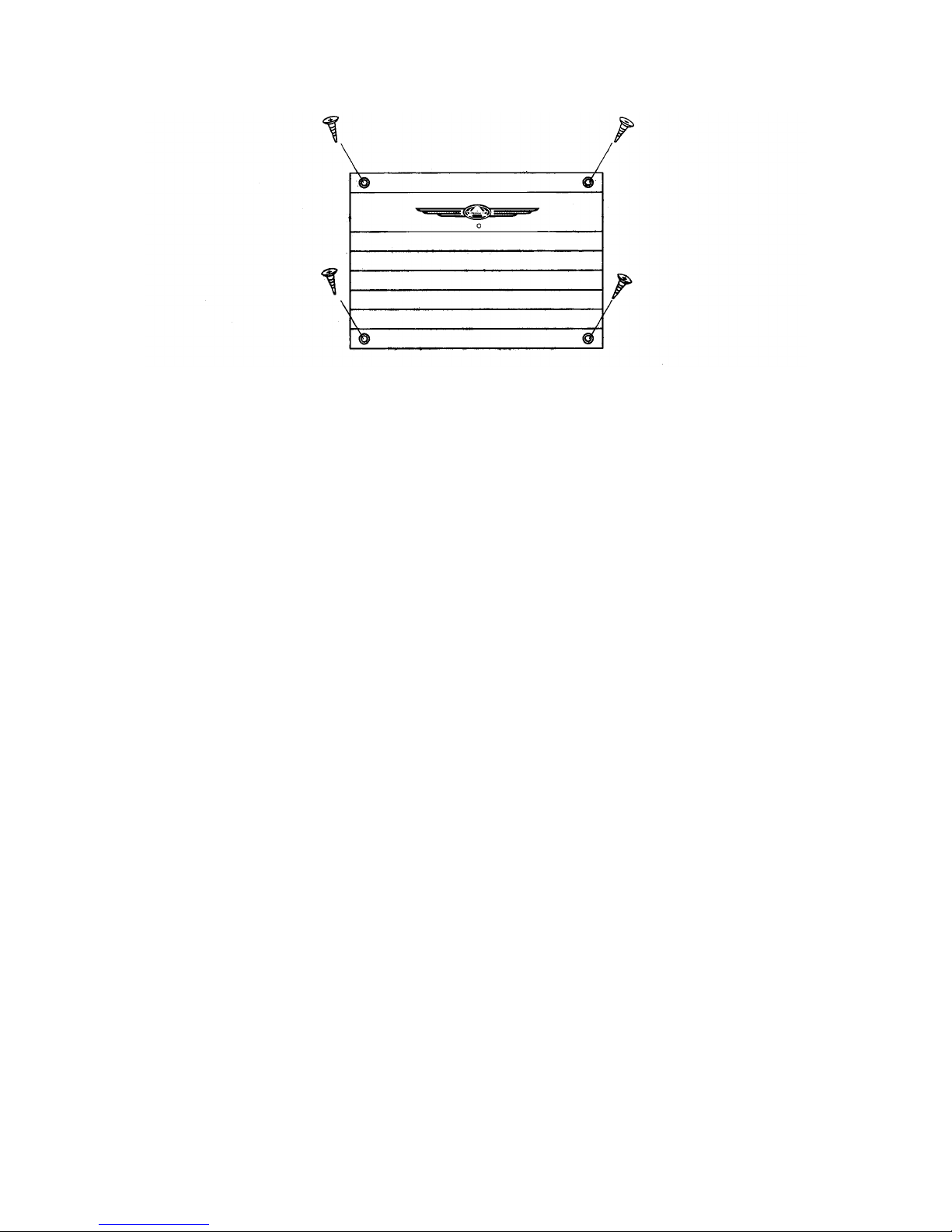
Fig. 1 Installation of amplifier
Power Supply Connections
The +12VDC and ground wires should be heavy gauge standard copper wire with heavy insulation. The
wire gauge should be 4AWG for the 300.S, 400.S, 500.S or larger. In addition it has a 12V remote control
wire and it should be 14AWG-18AWG. It is preferable to have longer speaker wires and shorter power
supply wires to minimize power losses.
+12V Power
This wire is usually connected directly to the positive battery terminal. Ensure that the + power supply wire
is fused via an assigned fuse in line with the + power supply wire. This connection must be completed by
using spade lug with insulating sleeve.
Ground
This connection must be completed by using spade lug with insulating sleeve. This wire is the electrical
ground and must be fastened securely to the vehicle chassis. The best method is to use a shelf threading
sheet metal screw since the threads cut into bare metal. Ensure that all paint coating or other insulation is
removed from around the hole are and using self tapping screw, securely affix the bare wire ends to the
vehicle chassis. Use as short a piece of cable as possible—use the same gauge as for the +12V.
Remote
Many radios or other music sources have an output terminal for connection of the remote turn -on of the
power amplifier. If a radio doesn’t have a remote turn -on feature, then you can use the antenna relay wire
which activates the antenna motor. But you must take notice if the power antenna retracts when the tape
player is operating. In this case, you can’t use the antenna relay wire to operate the remote turn-on.
 Loading...