

Page 1
NO / DKSE DEGB
INSTALLATIONSANVISNING
INSTALLATION INSTRUCTIONS
MONTAGEANLEITUNG
Comfort 2923
Page 2
2
SE DK NO
1
50 120 75
A
80
Ø58
B
215
66
132
3
C
BA
2
155
575
15
C
A
A
min 90
D
E
G
440
4
A
F
F
B
B
F
F
1710
min 1850
780
B
300
C
450
min 25
A
B
C
D
E
F
H
I
J
Ø 125
Ø 82
66
132
B
145
400
75
A
B
C
D
F
max 500
E
105
6
A
89
G
A
B
C
A
B
C
D
E
F
G
D
Page 3
3
SE DK NO
10
42 1
12
1411
B
E
+ -
C
D
A
1
4
2
5
3
6
A
B
G
13
A
B
B A
15
C
A
D
D
D
20
F
E
B
C
D
E
min 150
40
200
100
Page 4

4
SE DK NO
Sida Kapitel
4 1:0 Teknisk data
4 2:0 Montering av pannan
4 2:1 Montering av skorsten
5 2:2 Gasolinstallation
5 2:3 Montering av rumstermostat
5 2:4 Elinstallation
5 3:0 Montering av värmesystemet
6 3:1 Anslutning till värmesystemet
6 3:2 Fyllning av värmesystemet
6 4:0 Anslutning av varmvattenberedare
6 5:0 Installationskontroll
Läs noggrant igenom denna installationanvisning innan
pannan monteras.
Denna anvisning är godkänd för gasolpanna typ 2923
i husbil, husvagn och byggnad enligt CE nr 048 AO-
0006.
Vid efterkontroll av pannan skall nationella bestämmelser
följas.
1:0 Teknisk data.
Dimension: Höjd Bredd Djup
Pannans mått: 1710mm 132mm 220mm
Min. inbyggnadsmått: 1820mm 132mm 310mm
Med elpatron: 1820mm 132mm 420mm
Med elp. och vv-beredare:1820mm 132mm 450mm
Gas: Propan Butan
Effekt: 5,8 kW 6,7 kW
Gasförbrukning: Max 420 g/h Max 480 g/h
Gastryck: I3+ 28-30/37 mbar, I
Vikt gasolpanna: 18 kg
Vikt elpatron: 2,5 kg (0,5 kg till för motor)
Vikt varmvattenberedare 2959: 4,5 kg
Vätskevolym i panna: 2,6 liter
Vätskevolym i elpatron: 1,0 liter
30 mbar
3B/P
2:0 Montering av pannan.
Märk ut var pannan skall stå. Placeras pannan intill
en vägg eller motsvarande som består av brännbart
material, skall en 1 mm luftspalt lämnas.
Tag hål i golvet, ett för insugningsröret och ett för ventila-
tionstrumman, om sådan monteras (se g 1). Ventilation
strumman kan placeras antingen på höger eller vänster
sida, beroende på utrymme. Täck det upptagna hålet
för ventilationstrumman med ett nmaskigt nät. Montera
därefter skorstenen enligt kapitel 2:1.
Lägg en silikonsträng runt där pannan skall stå. Sätt
pannan på plats och skruva fast den i golv och vägg
(se g 2A).
Insugningsröret skall gå minst 25 mm under golvet (se
g 3), annars bör ett förlängningsrör monteras. Skruva
fast den svarta insugningstratten på in sugningsröret
under pannan.
Tag bort den fyrkantiga täckplåten på pannan där ventilations trumman skall sitta. Rulla ut plastslangen som ligger
bakom den nedre frontplåten. Skär av änden på slangen
så att den blir spetsig. Dra ut slangen genom ventilationstrumman och golvet. Skruva fast ventilations trumman
i golv och panna.
Om pannan monteras i t.ex. en garderob, bör en skiljevägg sättas dit, så att brännbart material ej kan komma
i kontakt med varma delar. Är varmvattenberedare och
elpatron monterade på pannan, gör då hål i skiljeväggen
enligt g 4 för att kunna komma åt varmvattenberedarens
luftskruv, avtappningskran samt återställnings knappen
för överhettnings skyddet på elpatronen.
2:0.1 Montering av panna inbyggd i
skåp.
Märk ut var pannan skall stå. Placeras pannan bredvid en
vägg eller motsvarande som består av brännbart material,
skall en 1 mm luftspalt lämnas. Framför pannan bör en
dörr eller servicelucka monteras så att manöverpanel och
expansionskärl är lätt åtkomligt. Avståndet framför pannan
till brännbart material bör vara minst 5 mm. Ventilation
från utrymmet där pannan är placerad, bör vara minst
10 cm2 vid tak och golv.
Tag hål i golvet, ett för insugningsröret och ett för ventilationstrumman, om sådan monteras (se g 1 i installationsanvisningen). Ventilation strumman kan placeras
antingen på höger eller vänster sida, beroende på
utrymme. Täck det upptagna hålet för ventilationstrum-
man med ett nmaskigt nät. Montera därefter skorstenen
enligt kapitel 2:1.
Lägg en silikonsträng runt där pannan skall stå. Sätt
pannan på plats och skruva fast den i golv och vägg (se
g 2A i installationsanvisningen).
Insugningsröret på 2923 skall gå minst 25 mm under
golvet (se g 3 i installationsanvisningen), annars bör
ett för längningsrör monteras. Skruva fast den svarta
insugningstratten på in sugningsröret under pannan (endast 2923).
Tag bort den fyrkantiga täckplåten på pannan där ventilations trumman skall sitta. Rulla ut plastslangen som ligger
bakom den nedre frontplåten. Skär av änden på slangen
så att den blir spetsig. Dra ut slangen genom ventilationstrumman och golvet. Skruva fast ventilations trumman
i golv och panna.
Om pannan monteras i t.ex. en garderob, bör en skiljevägg
sättas dit, så att brännbart material ej kan komma i kontakt
med varma delar. Är varmvattenberedare och elpatron
monterade på pannan, gör hål i skiljeväggen (2923 g
4 och 2928 g 3) för att kunna komma åt varmvattenbe-
redarens luftskruv, avtappningskran samt åter ställningsknappen för överhettnings skyddet på elpatronen.
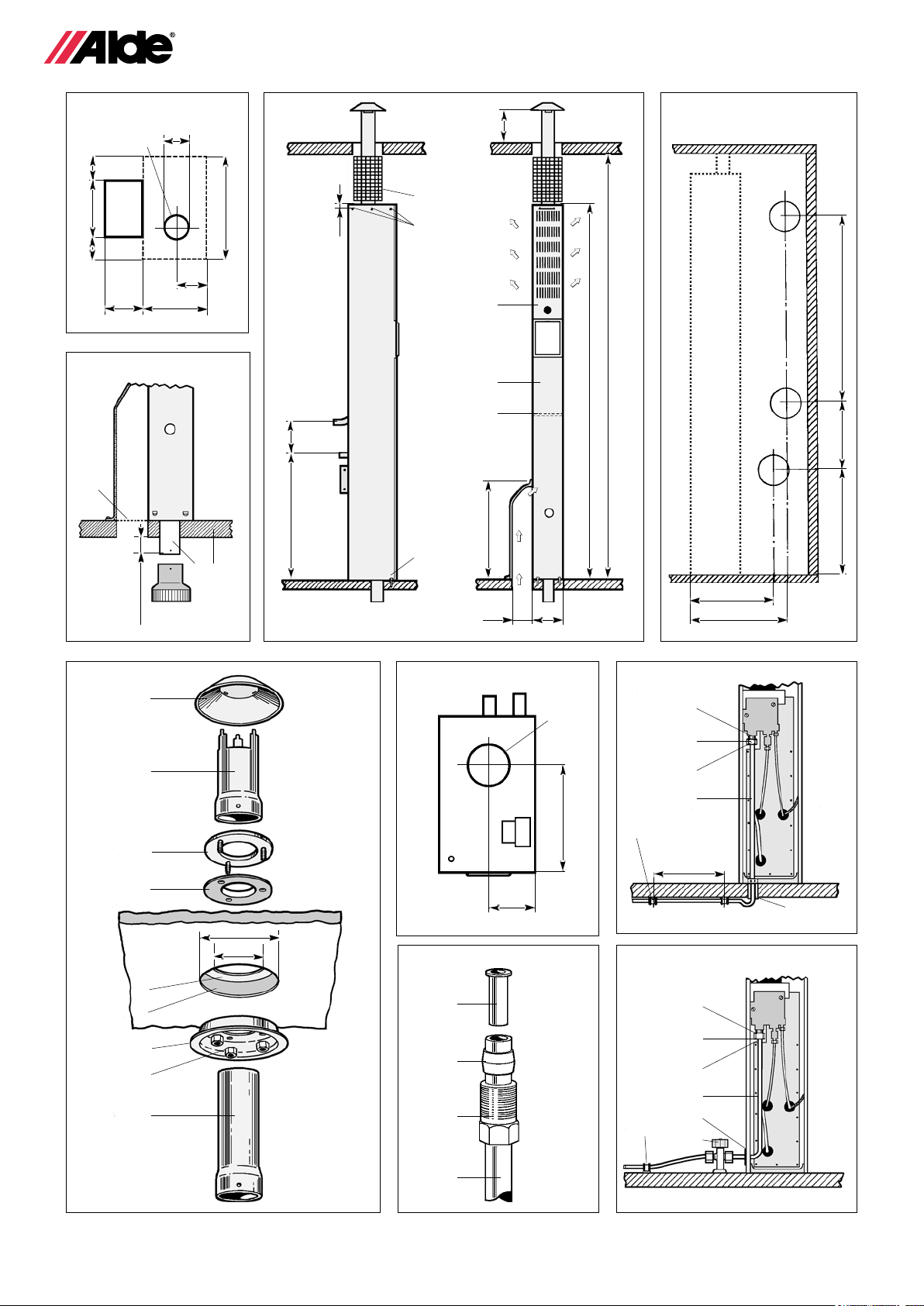
Fig 1
A. Hål för ventilationstrumma
B. Hål för insugningsrör
Fig 2
A. Hål för fastskruvning
B. Friskluft
C. Skydd för avgasröret
D. Övre frontplåt
E. Nedre frontplåt
F. Förvärmd friskluft
G. Bärhandtag
Page 5

5
SE DK NO
Fig 3
A. Insugningsrör
B. Golv
C. Finmaskigt nät
Fig 4
A. Hål för luftskruv på vv-beredare typ 2959.
B. Hål för avtappningskran på vv-beredare typ 2959.
C.Hål för återställningsknapp till överhettnings-
skyddet på elpatron.
2:1 Montering av skorsten.
Märk ut centrum där hålet skall göras (se g 6). Tag ett
Ø 125 mm hål i innertaket och isoleringen samt ett Ø 82
mm hål i ytterplåten. Montera därefter delarna B,C och
G och spänn fast muttrarna H (se g 5). För därefter in
avgasröret underifrån. Sätt pannan på plats (kap 2:0), och
skruva fast skorstensröret i pannans avgasrör. Observera
att då skorstensröret drages nedåt eller uppåt skall det
vridas runt samtidigt (smörj ev. med såpvatten). Sätt på
takhatten A och böj ikarna inåt. Minsta mått från tak till
skorstenshatt skall vara 90 mm.
Den fria delen av skorstensröret inne i vagnen skall
skyddas med nät eller plåt så att brännbart material ej
kan komma i direktkontakt (se g 2 C). Efterspänn ev.
muttrarna.
Fig 5
A. Hatt
B. Skorstensrör
C. Fästbricka
D. Packning
E. Ytterplåt
F. Isolering
G. Innertak
H. Distansbricka
I. Mutter
J. Förlängningsrör
Fig 6
A. Panna sedd uppifrån
B. Centrummarkering för skorsten
DANMARK
Danmarks Gasmateriel Prøvning ”Gasreglementets
afsnitt B-3 for F-gas anlæg i campingvogne” m.m. skall
tillæmpas. Vid installation i arbejdsskure og skurvogne
skall afsnitt B-2 tillæmpas.
NORGE
Statens branninspeksjon, Statens sprengstofnspeksjon
og Vegdirektoratets "Retningslinjer for gassinstallasjoner i
campingtilhengre" Januar 1981, følges vid installa sjon.
Om kopparröret dras under vagnen (fig 7):
I bottenplåten på pannan nns ett utstansat hål där kopparröret skall gå igenom. Borra hål genom golvet dra
upp kopparröret genom golvet och bottenplåten (glöm ej
nötningsskydda röret). Sätt dit stödhylsa, mutter och kona
(se g 9) och skruva fast i auto matikens gasanslut ning.
Täta genomgången i golvet med silikon eller liknande.
Om kopparröret dras inne i vagnen (g 8):
Ta bort täckbrickan på plåthöljets höger- eller vänstersida, beroende på vilket håll kopparröret kommer ifrån.
Skär hål för kopparröret i den medföljande gummibrickan
och sätt fast den där täckbrickan suttit. Trä igenom kopparröret och dra upp det i en mjuk böj till automatikens
gasanslutning. Sätt dit stödhylsa, mutter och kona (se
g 9) och skruva fast.
Fig 7-8-9.
A. Stödhylsa
B. Kona
C. Mutter
D. 8mm kopparrör
E. Nötningsskydd
F. Klammer
G. Avstängningskran
2:3 Montering av rumstermostat.
Rumstermostaten bör placeras på minst 1 meters höjd
över golvet, men ej för högt upp mot taket. Den bör ej
heller placeras på yttervägg, intill panna, spis, kylskåp
eller skorstensrör. Rumstermostaten startar och stannar
cirkulationspumpen efter värmebehov.
2:2 Gasolinstallation.
Pannan skall anslutas till en gasolaska med typgodkänd
reduceringsventil och ett tryck på 30 mbar (3 kPa). En
avstängningsventil för att kunna stänga av gasoltillförseln skall monteras före pannan. Gasolinstallationen
till pannan utföres med 8 mm rörledning av koppar eller
zinkbelagt stålrör. Om kopparrör används skall stödhylsor
monteras i kopplingar. Rörledningen skall klamras noggrant på 500 mm avstånd med klammer som ej nöter
på röret. Om rörledningen går igenom väggar, golv eller
dylikt skall den nötningsskyddas med skyddshylsa av
slang eller liknande. Rörledningen skall också vara skyddad mot överslag från elledningar.
SVERIGE
Sprängämnesinspektionens författningssamling, SÄIFS
1995:8 skall tillämpas vid installation.
2:4 Elinstallation.
12 VOLT
Den elektriska inkopplingen göres i toppen på pannan, där en sexpolig kopplingsplint är fastskruvad.
Använd medföljande kopplingsplint samt de fyra atstifts
kontakterna vid inkoppling. Från batteriet bör 1,5 mm2
kabel användas och från rumstermostaten 1 mm2.
Anslutningen skall ske till ett 12 volts bilbatteri eller speci-
ell batterieliminator. Inkopplingen skall ske enligt g 10.
230 VOLT (gäller endast elpatron)
Elpatronen skall alltid anslutas till ett 230 volts jordat
uttag. Fast installation av vägguttag till 230 volt, skall
utföras av behörig person enligt gällande föreskrifter.
12 volts styrkretsen från panna till elpatron är inkopplat
från fabrik. Kablar får ej läggas intill eller på elementbehållaren.
VARNING: 230 volt skall vara väl skiljt från 12 volt.
Page 6

6
SE DK NO
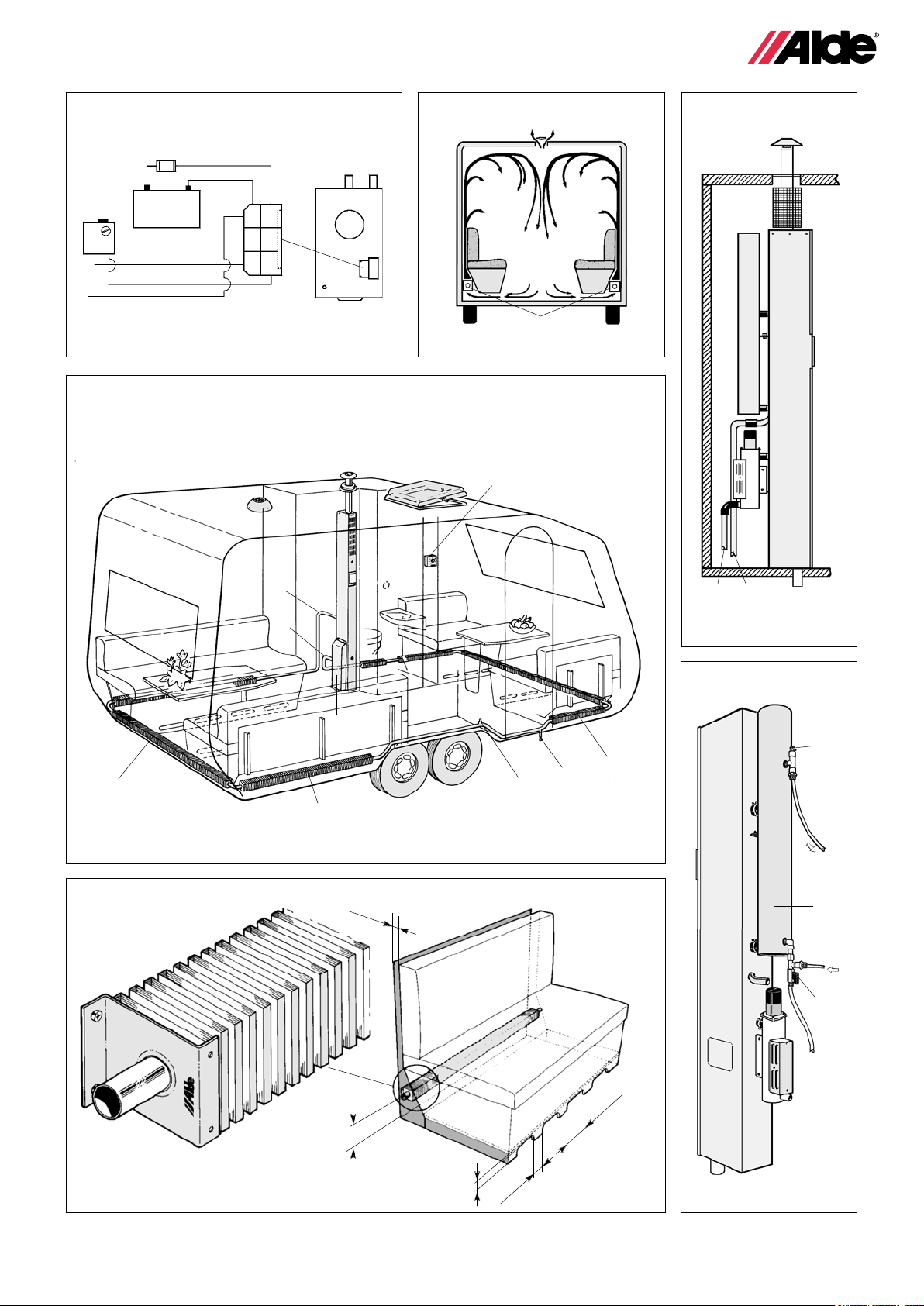
Fig 10.
A. Kopplingsplint
B. Säkring 1 amp
C. Rumstermostat
D. Batteri 12 volt
E. Panna sedd uppifrån
3:0 Montering av värmesystem.
För att erhålla bästa effekt av värmesystemet bör konvektorerna monteras utmed ytter väggarna och under
fönsterna (g 12). För att få korrekt luftcirkulation (g
11) och värme avgivning skall luft fritt kunna passera
mellan bäddbottnar - golv och ryggdynor - ytterväggar.
Det är alltså av yttersta vikt att luften får fritt tillträde till
konvektorerna, eftersom dessa skall leverera huvuddelen
av värmen som skall spridas i vagnen. Tages det ej hål
för luftspalter enligt g 13, kan ej konvektorerna avge
tillräckligt med värme, vilket medför kallras och kondens
vid fönster och ytterväggar.
Installationen utföres med Ø 22 mm rör och konvektorer.
OBS! Aluminium och koppar får ej blandas i värmesystemet, eftersom koppar "äter upp" aluminium. Det är även
mycket viktigt att man inte använder samma utrustning
för att t.ex. kapa och bearbeta koppar och aluminium.
Om t.ex. ett kopparspån kommer in i ett aluminiumrör
blir det med största sannolikhet hål i röret.
Hur många meter konvektorer behövs då i vagnen?
Varje meter konvektor har en värmeavgivning på ca 400
watt. Det viktigaste är att under varje fönster placera en
konvektor som är något längre än fönstret. Men som
ett riktmärke kan räknas, vagnens längd x 1,5 = antalet
meter konvektorer, men ju er meter konvektorer desto
bättre och jämnare värmeavgivning. Då kan man med
samma värmeav givning hålla lägre systemtemperatur i
pannan. Det sparar både gasol och ger en behagligare
värme. Rördragningen göres vågrätt, och luftskruvar placeras på lämpliga platser där luften ej själv kan försvinna,
t.ex. om röret dras upp på hjulhuset (g 12 E). I husbil
där rör har dragits upp i en sovalkov ovanför förarhytten,
är det mycket viktigt att luftskruvar placeras på högsta
punkterna. Alla böjar skall göras så mjuka som möjligt,
annars försvåras cirkulationen.
Se till att konvektorer och rör är ordentligt uppfästa med
konsoller. Som förbindning mellan konvektorer och rör
användes korta gummiförbindningar i specialgummi.
Gummiförbindningarna skall vara fastspända med trådklämmor. Som tätningsmedel mellan gummiförbindningarna bör Permatex Form-a-Gasket nr 3 användas. En
kran för avtappning av systemet monteras på ledningens
lägsta punkt (g 12 F).
Fig 11
A. Luftström
B. Konvektorer
Fig 12
A. Utgående vatten
B. Returvatten
C. Ventilationstrumma
D. Konvektor
E. Luftnippel
F. Avtappningskran
G. Rumstermostat
3:1 Anslutning till värmesystemet.
Gasolpannans anslutningar till värmesystemet är placerade på pannans baksida. Använd samma gummiförbindningar, klammer och tätningsmedel som till övriga
systemet.
Gasolpanna med varmvattenberedare typ 2959 och
elpatron monteras enligt g 14.
Fig 14
A. Utgående rör
B. Returrör
3:2 Fyllning av värmesystemet.
Värmesystemet skall fyllas med en vätskeblandning bestående av 60% vatten och 40% glykol. Använd glykol
av hög kvalité (med inhibitorer) avsedd för värmesystem.
Om värmeanläggningen utsätts för lägre temperatur än
-25°C skall glykolhalten höjas, dock ej över 50%.
Kärlen som vätskan hanteras i måste vara absolut rena
och rören i värmesystemet skall vara fria från föroreningar.
Detta för att förhindra bakterietillväxt i systemet.
Fyllning av systemet görs i expansionskärlet. Antingen
manuellt eller med hjälp av Aldes påfyllnadspump, som
både fyller på och luftar systemet. Vid manuell fyllning
hälls vätskan på sakta tills nivån är cirka 1 cm över MINstrecket på kärlet. Lufta systemet. Fyll på ytterligare om
nivån sjunkit vid luftning. Vid nyfyllt värmesystem, lufta
med jämna mellanrum de första dagarna värmen är
igång.
4:0 Anslutning av varmvatten beredare.
(Gäller endast om typ 2959 är monterad)
För att varmvattenberedaren skall fungera måste den
anslutas till färskvattensystemet. Från beredaren dras
sedan slangen med varmvatten vidare till t.ex. dusch,
termostat blandare eller diskbänk. På varmvattenberedaren används nipplar med 1/4"R gängor. Gängtape eller dyligt bör sättas i gängorna för att undvika
läckage.
Färskvattenanslutningarna är placerade på baksidan av
Page 7

7
beredaren. Inkommande vatten längst ner och utgående
längst upp. För att enkelt kunna tappa ut färskvattnet när
beredaren ej används, bör avtappningskran monteras
på inkommande anslutning och luftskruv på utgående
anslutning.
Fig 15.
A. Luftskruv
B. Varmt vatten
C. Varmvattenberedare
D. Kallt vatten
E. Avstängningskran
5:0 Installationskontroll.
Gasolsystemet:
• Provtryck alltid gasolanläggningen enligt gällande
bestämmelser efter installation eller service.
Om det skulle nnas läckage, lokalisera läckan med
läckspray eller såpvatten.
OBS! Öppen eld får ej användas vid läcksökning.
• Kontrollera att reduceringsventilen är på rätt tryck.
För att ytterligare öka säkerheten rekommenderas
montering av Alde gasolläckagetestare. Denna monteras närmast reduceringsventilen och med ett tryck på
en knapp kontrollerar man lätt om installationen är tät.
Värmesystemet:
• Värmesystemets täthet skall kontrolleras när hela
systemet är synligt dvs. innan inredningen monterats. Kontrollen kan ske på två sätt. Antingen prov
tryckning med 0.75 - 1,0 bar under 15 min, tryckminskning, max 0,05 bar, eller att fylla systemet med
vätska och kontrollera okulärt. Inget vätske läckage
accepteras.
• Kontrollera att alla slangklämmor är monterade och
rätt placerade.
Övrigt:
• Kontrollera att dräneringsslangen och avluftnings
slangen på expansionskärlet samt avtappningskranen på varmvattenberedaren (om sådan är monterad) ej är igentäppta.
• Kontrollera vid gummikopplingen på cirkulations
pumpen, att den snurrar åt rätt håll (motsols).
• Kontrollera att skorsten och skorstensrör sitter
på plats och är väl fastsatta, samt att insugningsslangen på Comfort 2928 är monterad på både
skorsten och panna.
• Kontrollera att luft fritt kan passera genom
ventilationstrumman.
SE DK NO
Page 8

8
GB
Page Chapter
10 1:0 Technical data
10 2:0 Fitting the boiler
10 2:1 Fitting the ue terminal
11 2:2 Installation of LPG
11 2:3 Fitting of room thermostat
11 2:4 Electrical installation
11 3:0 Fitting the heating system
12 3:1 Connection to the heating system
12 3:2 Filling the heating system
12 4:0 Connection to hot water heater
12 5:0 Installation inspection
Read through these installation instructions carefully
before tting the boiler.
The installation instructions are approved in accordance
with CE no. 048 AO-0006 for LPG boiler type
2923.
In connection with follow-up inspection of the boiler,
national regulations must be followed.
IMPORTANT WARNING!
No unit should be installed in any enclosed space unless
additional permanent ventilation of 100 cm2 is provided.
No alteration or adjustment should be made to any gas
burner or gas supply by unauthorised or unskilled persons. In the event of a failure or breakdown, turn off the
gas supply at the cylinder and contact the authorised
dealer or supplier.
The installation must be carried out in accordance with
the relevant British Standard of Practice. (Particulary
BS5482 Parts 1, 2 and 3).
The Gas Safety Regulations issued by the Dept. of the
Environment, the Building Standards (Scotland) (Consolidaton) Regulations issued by the Scottich Develop ment
Department.
In any communication it is essential to quote the model
and serial number shown on the data badge.
1:0 Technical data
Dimensions: Height Width Depth
Boiler dimensions: 1710mm 132mm 220mm
Min. space required: 1820mm 132mm 310mm
With immersion heater: 1820mm 132mm 420mm
With immersion heater
and water heater: 1820mm 132mm 450mm
Gas: Propane Butane
Power: 5,8 kW 6.7 kW
Gas consumption: Max 420 g/h Max 480 g/h
Gas pressure: I3+ 28-30/37 mbar, I
Weight of LPG boiler: 18 kg
Weight of immersion heater: 2.5 kg (plus 0.5 kg
for motor)
Weight of water heater 2959: 4,5 kg
Liquid volume in boiler: 2.6 litres
Liquid volume in immersion heater: 1.0 litre
30 mbar.
3B/P
2:0 Fitting the boiler
Mark out where the boiler is to stand. If the boiler is to be
positioned against a wall or bulkhead made of a inammable material, a 1 mm air gap must be allowed.
Make holes in the oor, one for the ventilation duct and
one for the inlet pipe (see g 1). The ventilation duct can
be placed either on the right-hand side or the left-hand
side, depending on space available. Cover the hole for
the ventilation duct with ne mesh netting. Fit the chimney
according to chapter 2:1.
Put a strip of realant round where the boiler is to stand.
Position the boiler and screw it in place on the oor and
wall at A g 2.
The inlet pipe should be at least 25 mm under the oor
(see g 3). If not, use a extension pipe. Screw the black
inlet funnel to the inlet pipe under the boiler. Remove
the square panel on the side boiler where the ventilation
duct is to be tted by pressing the panel out from inside
the boiler casing and cutting the insulation around the
aperture with a sharp knife. Uncoil the overow hose
and pass down through the duct and out through the
hole in the oor. Screw the duct to the oor and the side
of the boiler.
If the boiler is tted in a cupboard a partition should be
installed to prevent inammable materials from contacting
hot parts of the casing etc. When immersion or water
heaters are tted cut holes in the partition, as g. 4 for
access to the water heater air cock and the overheat
reset button for overheating protection on the immersion
heater.
2:0.1 Mounting a boiler in a cupboard
Mark out where the boiler is to stand. An air-space of
1 mm must be left if the boiler is to be placed next to a
wall or anything else that consists of ammable material.
A door or service hatch should be placed in front of the
boiler so that the control panel and the expansion tank
are easily accessible. The minimum distance in front of
the boiler to any ammable material should be 5 mm.
Ventilation areas for the space which the boiler is to occupy should be at least 10 cm2 at the oor and the roof.
Make holes in the oor, one for the input tube and one for
the ventilation drum, if one is to be mounted (see Figure
1 in the installation instructions). The ventilation drum
can be placed either to the left or to the right, depending
on the space available. Cover the hole prepared for the
ventilation drum with nemeshed netting. Then mount
the chimney as described in Chapter 2:1.
Place a bead of silicone around the position where the
boiler is to be placed. Put the boiler into position and x
it by screws to the oor and wall (see Figure 2A in the
installation instructions). The input tube on 2923 must
protrude at least 25 mm below the oor (see Figure 3
in the installation instructions); an extension tube must
be tted if it does not extend this far. Screw the black
input funnel onto the input tube under the boiler (only
valid for 2923).
Page 9

9
GB
Remove the square covering plate from the boiler where
the ventilation drum is to be attached. Roll out the plastic
hose that lies behind the lower front plate. Cut off the end
of the hose to make it pointed. Feed the hose out through
the ventilation drum and the oor. Attach the ventilation
drum to the oor and the boiler by screws.
If the boiler is to be mounted in a wardrobe, for example,
a dividing wall should be mounted so that ammable
material cannot come into contact with any warm parts.
If a water heater and electrical cartridge are mounted
on the boiler, make a hole in the dividing wall (2923
Figure 4 and 2928 Figure 3) in order to gain access to
the air-screw and drainage tap of the water heater and
to the reset button for the overheating protection on the
electrical cartridge.
Fig 1
A. Hole for ventilation duct
B. Hole for inlet pipe
Fig 2
A. Hole for attaching boiler
B. Fresh air
C. Protection for the exhaust pipe
D. Upper front plate
E. Lower front plate
F. Preheated fresh air
G. Carrying handle
Fig 3
A. Inlet pipe
B. Floor
C. Fine mesh netting
Fig 4
A. Hole for air screw on water heater type 2959.
B. Hole for drain cock on water heater type 2959.
C. Hole for reset button for overheating protection
on immersion heater.
2:1 Fitting the chimney.
Mark out the centre where the hole is to be made (see g
6). Cut a Ø 125 mm hole in the ceiling and the insulating
material and a Ø 82 mm hole in the roof. Then assemble
the parts B,C and G and fasten the nuts H (see g 5).
Then bring the chimney pipe in from underneath. Place
the boiler (chapter 2:0) and pull the chimney pipe down
and attach it to the stud on the boiler using a self-tapping screw.
NB! When the chimney pipe is pulled up or down it
should at the same time be twisted (grease it with suds
if necessary).
Put on the cap and bend the retaining lugs inwards. The
distance from the roof to the cap should be at least 90
mm (see g 2).
The exposed section of the chimney pipe inside must be
protected with mesh or metalsheet so that inammable
material cannot come into direct contact with the exhaust
pipe (see g 2 C).
Fig 5
A. Cap
B. Flue pipe
C. Plate
D. Gasket
E. Outer plate at the roof
F. Insulation
G. Ceiling
H. Spacer
I. Nut
J. Extension pipe
Fig 6
A. The boiler from above
B. Centre marking for the chimney
2:2 LPG installation
The boiler should be attached to an LPG cylinder with a
type-approved regulator with a pressure of 28 mbar with
butane or 37 mbar with propane. A service tap to cut off
the gas supply must be tted before the boiler. The boiler
should be connected with 8 mm copper pipe. The pipe
must be secured carefully at 500 mm intervals througout
its length. If the copper pipe passes through walls, oors
or similar it should be protected against wear by a grommet or insulation.
If the copper pipe is run under the caravan (g
7):
In the base plate of the boiler there is a ready-punched
hole for the copper pipe to pass through. Drill a hole
through the oor where the copper pipe is to enter. Pull
the copper pipe up through the oor and the base plate
(don’t forget to protect the pipe against wear). Use a
supporting sleeve, nut and olive (see g 9) and screw
the pipe to the gas connection of the gas valve. Seal the
hole in the oor with silicon or similar.
If the copper pipe is run inside the caravan (g
8):
Remove the disc on the right or left-hand side of the metal
case, depending on which side the copper pipe comes
from. Cut a hole in the rubber washer and attach it where
the disc was. Push the copper pipe through and pull it up
in a gentle curve to the gas valve. Use a nut and olive
(see g 9) and screw the pipe to the connection of the
gas valve on the burner.
Figs 7-8-9
B. Olive
C. Nut
D. 8 mm copper pipe
E. Rubber grommet
F. Pipe clip
G. Service tap
2:3 Fitting the room thermostat
The room thermostat should be placed at least 1 metre
above the oor, but not too close to the ceiling. It should
not be placed on an outer wall, beside the boiler, cooker,
fridge or ue. The room thermostat starts and stops the
circulation pump according to the heat requirement.
Page 10

10
GB
2:4 Electrical installation
12 volts
The electrical connection is made at the top of the boiler,
where a sixpole terminal block is tted. Use the accompanying terminal plug and the four spade connectors.
From the battery, a 1.5 mm2 cable should be used and
from the room thermostat a 1 mm2 cable. The connection
should be made to a 12-volt car battery or to a special
battery eliminator. The connection should be made in
accordance with g 10.
230 volts (immersion heater only)
The immersion heater must always be connected to
a 230-volt earthed socket. Permanent installation of a
230-volt wallsocket must be made. Keep cables clear of
immersion heater body.
WARNING: 230 volts must be well shielded from 12
volts.
Fig 10.
A. Terminal block
B. Cut-out 1 amp fuse
C. Room thermostat
D. Battery 12 volts
E. The boiler from above
3:0 Fitting the heating system
In order to obtain the best effect from the heating system,
the radiators should be tted along the outer walls and
under the windows. In order to obtain good air circulation
(g 11) and correct heat emission, fresh air should be able
to pass between bed bases, oor and back cushions and
outer walls (see g 12). It is therefore extremely important
that air gains free access to the radiators, as these are
to supply the majority of the heat to be distributed inside
the caravan. If no holes are made for air gaps as per g
13, the radiators will not be able to emit sufcient heat,
which will lead to a sharp fall in temp era ture at windows
and outer walls, leading to condensa tion.
Installation should be carried out using Ø 22 mm pipe
and any type of radiator. Radiators constructed of copper
piping are most efcient. Every metre of radiator has a
heat emission of about 400 watts. Pipes and radiators
must not be placed higher than the bottom of the boiler’s
expansion vessel. If there are upper alcoves in vehicles,
The boiler must be raised on a plinth se g 12.
How many metre’s of radiator are required in the caravan?
The most important thing is to have a radiator under
each window that is slightly longer than the window. A
useful guide is the length of the caravan legth x 1.5 =
the number of metres of radiators, but the greater the
length of radiator, the better and more even the heat
distribution. This allows a lower system temperature in
the boiler for the same heat emission. This saves gas
and provides a more pleasant heat. The pipes should
be run horizontally and air screws should be located at
suitable places where air cannot escape by itself, e.g.
if the pipe is run over the wheel housing (see g 12 E).
In vehicles, if there is a sleeping alcove above the driver’s
cab, it is very important to locate air screws at the highest point. All curves should be as gentle as possible,
otherwise circulation is obstructed.
Make sure that radiators and pipes are properly attached
with brackets. As a connection between radiators and
pipes, short rubber connections made of special rubber should be used. The rubber connections should be
secured with wire clips. A sealant between the rubber
connections, Permatex Form-a-Gasket no. 3 should be
used. A draining valve should be tted to the lowest point
of the pipe (see g 12 F).
NB. Aluminium and copper must not be mixed in the
heating system, because the copper corrodes the
aluminium. It is even very important not to use the
same equipment for cutting and handling copper and
aluminium. If a copper shaving, for example, gets into
an aluminium pipe, it will almost certainly give rise
to a hole in the pipe.
Fig 11
A. Air ow
B. Radiators
Fig 12
A. Circulation ow
B. Circulation return
C. Ventilation duct
D. Radiator
E. Air nipple
F. Drain cock
G. Room thermostat
3:1 Connection to the heating system
The LPG boiler’s connections to the heating system
are located on the rear of the boiler. Use the same rubber connections, clips and sealant as for the rest of the
system.
LPG boiler with water heater type 2959 and immersion
heater should be tted in accordance with g 14.
Figs 14
A. Flow radiator water
B. Return radiator water
3:2 Filling the heating system
The heating system must be lled with a liquid mixture
consisting of 60% water and 40% glycol. Use high quality
glycol that is designed for heating systems and contains
inhibitors. If the heating system is exposed to temperatures lower than -25 °C, the glycol percentage is to be
increased, but it should not exceed 50%.
Page 11

11
GB
Vessels used to handle the liquid must be absolutely
clean, and the pipes in the heating system must be
free from contamination. This is necessary to prevent
the growth of bacteria in the system. Filling is carried
out through the expansion tank, either manually or
with the aid of Alde’s lling pump. This pump both lls
and bleeds the system. If the system is lled manually,
slowly pour the liquid until the level is approximately
1 cm over the MIN-line in the tank. Bleed the system.
Rell if the level has fallen during bleeding. A newly lled
heating system should be bled at regular intervals during
the rst few days of operation.
4:0 Connection to hot water heater
(Applies only if a water heater is tted)
In order for the water heater to work, it must be connected
to the fresh water system. From the heater, the hot water
hose should run to the shower, thermostat mixer, sink,
etc. On the water heater, connections 1/4"R should be
used. P.T.F.E. tape or similar should be used a thread of
connections to avoid leakage.
The fresh water connections are located on the rear of
the heater. Incoming water at the bottom and outgoing
water at the top. So that the fresh water can be easily
drained off when the heater is not in use, a drain cock
should be tted to the incoming connection and an air
screw on the outgoing connection.
Fig 15
A. Air screw
B. Hot water
C. Water heater
D. Cold water
E. Drain cock
The heating system:
• The heating system should be tested for leaks when
the complete system is visible, that is, before any t-
tings are mounted. Two methods are possible: either
test pressurisation at 0.75 - 1.0 bar for 15 minutes,
followed by reduction of the pressure to a maximum
of 0.05 bar; or by lling the system with liquid and
checking by inspection. No leakage of liquid can be
accepted.
• Check that all hose clips are tted and correctly placed.
Other points:
• Check that the drainage tubes and the bleed tube on
the expansion tank are not blocked, and check that
the drainage tap on the water heater (if mounted) is
not blocked.
• Check that the circulation pump rotates in the correct
direction (anticlockwise) at the rubber connection.
• Check that the chimney and the chimney pipe are
correctly placed and securely attached, and check
that the input tube on the Comfort 2928 is mounted
on both chimney and boiler.
· Check that air can pass freely through the ventilation
drum.
5:0 Installation inspection
The LP gas system:
• After installation or service, always test the LP gas
installation under pressure following currently valid
regulations.
• If a leak is present, nd the leak using leak detection
spray or soapy water.
Note: open ames must not be used during leak
localisation.
• Check that the reduction valve is at the right pressure.
We recommend the mounting of an Alde LP gas leakage
tester in order to further increase safety. The tester is
mounted closest to the reducing valve and enables you
to test that the system does not leak by simply pushing
a button.
Page 12

12
DE
Seite Kapitel
13 1:0 Technische Daten
13 2:0 Installation des Kessels
13 2:1 Aufbau des Schornsteins
14 2:2 Flüssiggasinstallation
14 2:3 Anbringung des Raumthermostates
14 2:4 Installation der elektrischen Anlage
14 3:0 Installation der Heizanlage
15 3:1 Anschluß an das Heizsystem
15 3:2 Auffüllung des Heizsystems
15 4:0 Anschluß des Heißwasserbereiters
15 5:0 Installationsüberprüfung
Lesen Sie diese Anleitung vor Montage des Heizgeräts genau durch. Diese Anleitung ist für Heizung Typ
2923 zur Montage in Wohnwägen, Wohnmobilen und
Gebäuden nach CE Nr 048 AO-0006 zugelassen.
Bei Nachkontrolle des Heizgeräts ist den nationalen
Bestimmungen Folge zu leisten.
1:0 Technische Daten
Maße: Höhe Breite Tiefe
Kessel: 1710 mm 132 mm 220 mm
Mindesteinbaumaße: 1820 mm 132 mm 310 mm
Mit Elektropatrone: 1820 mm 132 mm 420 mm
Mit Elektropatrone und
Heißwasserbereiter: 1820 mm 132 mm 450 mm
Gas : Propan Butan
Leistung 5,8 kW 6,7 kW
Gasverbrauch: max. 420 g/h max. 480 g/h
Gasdruck: I3+ 28-30/37 mbar, I
Gewicht Flüssiggaskessel: 18 kg
Gewicht Elektropatrone: 2,5 kg (0,5 kg Motor)
Gewicht Heißwasserbereiter 2959: 4,5 kg
Flüssigkeitsvolumen im Kessel: 2,6 l
Flüssigkeitsvolumen im Elektropatr: 2,6 l
30 mbar
3B/P
2:0 Installation des Kessels
Installationsort des Kessels kennzeichnen. Wird der Kessel an einer brennbaren Wand oder ähnlichem Material
aufgestellt, so ist ein Luftspalt von 1 mm freizulassen.
Löcher in den Boden bohren, eins für das Ansaugrohr
und eins für den Frischluftkasten, falls vorgesehen
(siehe Abb. 1). Der Frischluftkasten kann je nach den
vorhande nen Bedingungen entweder rechts oder links
angebracht werden. Das Loch für den Frischluftkasten
mit einem feinmaschigen Netz abdecken. Anschließend
Schornstein gemäß Kapitel 2:1 montieren.
Um die Aufstellungsäche des Kessels einen Silikon
streifen legen. Kessel anbringen und an Boden und Wand
festschrauben (siehe Abb. 2A).
Das Ansaugrohr muß mindestens 25 mm unter den Boden reichen (siehe Abb. 3), andernfalls ist ein Ver länger ungsrohr anzubringen. Den schwarzen Ansaugtrichter
des Ansaugrohres unter dem Kessel festschrauben.
Das viereckige Abdeckblech vom Kessel an der Stelle
entfernen, an der sich der Frischluftkasten benden soll.
Den hinter dem unteren Verkleidungsblech bendlichen
Plastikschlauch ausrollen, dessen Ende spitz zuschneiden und durch Frischluftkasten sowie Boden verlegen.
Frischluftkasten an Boden und Kessel festschrauben.
Wird der Kessel z.B. in einem Schrank installiert, sollte
eine Trennwand eingebaut werden, damit brennbares
Material nicht mit heißen Teilen in Berührung kommen
kann. Sind Heißwasserbereiter und Elektro patrone am
Kessel montiert, so ist gemäß Abb. 4 ein Loch in die
Trennwand zu machen, damit Entlüftungs schraube, Ablaßhahn sowie Rückstelltaste des Überhitzungs schutzes
an der Elektropatrone zugänglich sind.
2 :0.1 Montage eines Kessels, der in
einem Schrank eingebaut ist.
Den Standort des Kessels markieren. Wird der Kessel in
Wandnähe oder in der Nähe von brennbarem Material
installiert, ist ein Luftspalt von 1 mm erforderlich. Vor
dem Kessel sollte eine Tür oder ein Inspektionsdeckel
auf eine solche Art und Weise montiert werden, dass sowohl Bedienungstafel als auch Expansions behälter leicht
zugänglich sind. Der Abstand vor dem Kessel zu brennbarem Material sollte mindestens
5 mm betragen. Die Ventilation im Raum, wo der Kessel
installiert ist, sollte mindestens 10 cm2 an Decke und
Boden sein.
Im Boden ein Loch für das Ansaugrohr und, wenn eine
solche montiert wird, ein Loch für die Ventilations trommel
(siehe Abb. 1 in der Installationsanleitung) bohren. Die
Ventilationstrommel kann, abhängig vom Raum, entweder auf der rechten oder linken Seite montiert werden.
Die Ausnehmung für die Ventilations trommel mit einem
feinmaschigen Netz abdecken. Danach den Schornstein
gem. Kapitel 2 :1 montieren.
Einen Silikonstrang um die Stelle legen, auf welcher der
Kessel stehen soll. Den Kessel an seinen Standort setzen
und ihn im Boden und der Wand (siehe Abb. 2A in der
Installationsanleitung) festschrauben.
Das Ansaugrohr des Kessels 2923 soll mindestens 25
mm unter dem Boden verlaufen (siehe Abb. 3 in der
Installationsanleitung). Anderenfalls ist ein Verlängerungsrohr zu montieren. Den schwarzen Ansaug trichter
auf dem Ansaugrohr unter dem Kessel (nur 2923)
festschrauben.
Das viereckige Abdeckblech auf dem Kessel, wo die
Ventilationstrommel sitzen soll, abnehmen. Den Kun ststoffschlauch, der hinter dem unteren Frontblech liegt,
ausrollen. Das Schlauchende spitz zuschneiden. Den
Schlauch durch die Ventilationstrommel und den Boden
ziehen. Die Ventilationstrommel im Boden und Kessel
festschrauben. Wird der Kessel z.B. in einem Schrank
montiert, ist eine Trennwand einzusetzen, so dass kein
brennbares Material mit warmen Teilen in Kontakt kommt.
Sind auf dem Kessel ein Warmwasser bereiter und eine
Elektropatrone montiert, sind in die Trennwand Löcher
zu bohren (2923, Abb. 4 und 2928, Abb. 3), so dass die
Entlüftungsschraube des Warm wasserbereiters, der
Abzapfhahn sowie der Rück stellknopf für den
Überhitzungsschutz auf der Elektro patrone zugänglich
sind.
Page 13

13
DE
Abb. 1
A. Loch für Frischluftkasten
B. Loch für Ansaugrohr
Abb. 2
A. Loch zur Befestigung des Kessels
B. Frischluftzufuhr
C. Schutznetz oder -blech für das Abluftrohr
D. Obere Blechverkleidung
E. Untere Blechverkleidung
F. Vorgewärmte Frischluft
G. Tragegriff
Abb. 3
A. Ansaugrohr
B. Fußboden
C. Feinmaschiges Netz
Abb. 4
A. Loch für Entlüftungsschraube am Heißwasser-
bereiter 2959
B. Loch für Ablaufhahn am Heißwasserbereiter 2959
C. Loch für Rücknahmetaste des Überhitzungs-
schutzes an der Elektropatrone
2:1 Installation des Schornsteins
Mittelpunkt des herzustellenden Lochs kennzeichnen
(siehe Abb. 6). An der Decke ein Loch mit einem Durchmesser von 125 mm durch die Isolierung bohren. Im
Aluminium des Dachs ein Loch mit einem Durch messer
von 82 mm herstellen. Anschließend die Bauteile B, C
und G anbringen und die Muttern H anziehen (siehe abb
5) und das Schornsteinrohr am Abluftrohr des Kessels
festschrauben 8siehe kapitel 2:0). Dabei ist zu beachten,
daß das Schornsteinrohr bei Bewegungen nach unter
oder oben gleichzeitig gedreht werden muß (eventuell
mit Seifen lauge schmieren). Der in Abbildung 22 zu sehende Silikonschlauch muß über das Abgasrohr und den
Abgasstutzen gezogen werden. Kamindeckel anbringen
und Laschen nach innen biegen. Der Mindestabstand
zwischen Dach und Schornsteinabdeckung muß 90 mm
betragen.
Der freiliegende Teil des Schornsteinrohres innen im
Wagen ist durch ein Netz oder Blech zu schützen, damit
brennbares Material nicht direkt mit ihm in Berührung
kommen kann (siehe Abb. 2 C). Muttern eventuell nochmals anziehen.
Abb. 5
A. Kamindeckel
B. Kaminrohr
C. Unterlegscheibe
D. Dichtung
E. Außenblech
F. Isolierung
G. Innendecke
H. Abstandhalter
I. Mutter
J. Verlängungsrohr
Abb. 6
A. Kesseldraufsicht
B. Mittenmarkierung für den Schornstein
2:2 Flüssiggasinstallation
Die Flüssiggasinstallation ist nach den technischen
Regeln Flüssiggas Arbeitsblatt G 607 auszuführen. Im
unteren Teil des Kessels bendet sich (Abb. 7e und Abb.
8e) ein vorgestanztes Loch, in dem die Gaszufuhrleitung
installiert werden kann. In der Brennerautomatik bendet sich ein 10 cm langes Rohr, an dem die Gaszufuhr
angeschlossen wird.
2:3 Anbringung des Raumthermostates
Das Raumthermostat ist in einer Höhe von mindestens 1
m über dem Fußboden, aber auch nicht zu dicht an der
Decke anzubringen. Es sollte auch nicht an einer Außenwand, neben dem Kessel, am Herd, Kühlschrank oder
Schornsteinrohr montiert werden. Der Raum thermostat
schaltet die Umwälzpumpe je nach Wärmebedarf.
2:4 Elektroinstallation
12 Volt
Der elektrische Anschluß wird oben auf dem Kessel hergestellt, wo ein sechspoliger Anschlußstecker
festgeschraubt ist. Für die Stromversorgung sind der
beiliegende Stecker sowie die fünf Flachkontakte zu
verwenden. Von der Batterie sollte ein 1,5mm2-Kabel
verwendet werden. Der Anschluß erfolgt an eine 12 VAutobatterie oder eine für den Wohnbereich vorgesehene
Batterie oder ein spezielles Batterie-Ersatzgerät gemäß
Abb. 10.
230 V (nur Elektropatrone)
Die Elektropatrone darf nur an einen geerdeten 230 VAnschluß angeschlossen werden. Die feste Installation
einer Steckdose ist gemäß den geltenden Vorschriften
von einem Fachmann vorzunehmen. Der 12 V-Schaltkreis vom Kessel zur Elektropatrone ist bereits ab Werk
vorhanden. Kabel nicht neben oder auf den Heizkörper
legen.
Achtung! 230 V von 12 V trennen!
Abb. 10
A. Anschlußstecker
B. Sicherung 1 Amp.
C. Raumthermostat
D. Batterie 12 V
E. Kesseldraufsicht
3:0 Installation der Heizanlage
Um die bestmögliche Leistung aus dem Heizsystem
herauszuholen, sollten die Heizkörper an den Außenwänden und unter den Fenstern angebracht werden
(siehe Abb. 12). Damit Luftzirkulation (Abb. 11) und
Wärmeabgabe richtig funktionieren, sollte die Luft frei
zwischen den Bettenböden und dem Fußboden sowie
zwischen Rückenlehnen und Außenwänden zirkulieren
können.
Page 14

14
DE
Es ist also äußerst wichtig, daß die Luft freien Zugang
zu den Heizkörpern hat, das diese den Hauptanteil der
Wärme liefern, die das Fahrzeug innere erwärmen soll.
Werden keine Luftspalte gemäß Abb. 13 gelassen, so
können die Heizkörper nicht ausreichend Wärme abgeben, so daß es zu Kältebrücken und Kondenswasserbildung an Fenstern und Außen wände kommt.
Die Installation erfolgt mit 22mm-Rohren und beliebigen
Heizkörpern. Am leistungsstärksten sind Kupferrohr-Heizkörper. Jeder Meter Heizkörper hat eine Wärme abgabe
von etwa 400 Watt. Rohrleitungen und Heizkörper dürfen
nicht höher als der untere Teil des Ausdehnungs gefäßes
liegen (z.B. Alkoven-Einbau), sonst muss der Kessel auf
einen Sockel gestellt werden.
Wieviele Meter Heizkörper braucht man also pro Fahrzeug?
Das Wichtigste dabei ist, daß unter jedem Fenster ein
Heizkörper angebracht wird, der etwas länger als das
Fenster ist. Als Richtwert kann hierbei Wohnbereich x 1,5
= Anzahl Heizkörpermeter gelten, mehr Meter Heizkörper
sorgen jedoch für eine bessere und gleichmäßigere Wärmeverteilung. Dadurch wird bei gleicher Wärme -abgabe
wiederum eine niedrigere Systemtemperatur im Kessel
möglich, was sowohl Gas spart und für eine angenehmere Wärme sorgt.
Die Rohrverlegung erfolgt waagerecht unter Anbringung
von Entlüftungsschrauben an geeigneten Stellen, an denen die Luft nicht entweichen kann, z.B. beim Verlauf des
Rohres über dem Radkasten (abb 12 E). Wurden Rohre
im Wohnmobil nach oben in den Alkoven-Einbau über
dem Fahrerhaus verlegt, ist es äußerst wichtig, dort am
höchsten Punkt eine Entlüftungsschraube anzu bringen.
Alle Biegungen sind so weich wie möglich auszuformen,
da andernfalls die Zirkulation verschlechtert wird.
Heizkörper und Rohre ordentlich mit Tragwinkeln befestigen. Als Verbindungsstück zwischen Heizkörper und
Rohr sind Spezialgummianschlüsse zu verwenden, die
mit Drahtklammern befestigt werden. Als Dichtungsmittel zwischen den Gummianschlüssen sollte Permatex
Form-a-Gasket Nr. 3 verwendet werden. Ein Systemablaufhahn ist am tiefsten Punkt der Leitung anzubringen
(abb 12 F).
Achtung! Im Heizsystem dürfen Aluminium und Kupfer
nicht zusammen verwendet werden, da Kupfer das
Aluminium „ausst“. Es ist ebenfalls sehr wichtig, dass
z.B. für das Schneiden und die Bearbeitung von Kupfer
und Aluminium nicht die gleiche Ausrüstung benutzt
wird. Gelangen z.B. Kupferspäne in ein Aluminiumrohr,
wird das Rohr mit größter Wahrscheinlichkeit allmählich
Löcher aufweisen.
Abb. 11
A. Luftstrom
B. Heizkörper
Abb. 12
A. Vorlaufwasser
B. Rücklaufwasser
C. Frischluftkasten
D. Heizkörper
E. Entlüftungsnippel
F. Entleerungshahn
G. Raumthermostat
3:1 Anschluß an das Heizsystem
Die Anschlüsse des Flüssiggaskessels an das Heiz-
system benden sich auf der Rückseite des Kessels.
Hier sind dieselben Gummianschlüsse, Klammern und
Dichtungsmittel wie im übrigen System zu verwenden.
Der Flüssiggaskessel mit Heißwasserbereiter Typ 2959
und Elektropatrone wird nach Abb. 14 montiert.
Abb. 14
A. Vorlauf Heizkörperwasser
B. Rücklauf Heizkörperwasser
3:2 Auffüllung des Heizsystems
Das Heizsystem ist mit einem Flüssigkeitsgemisch, bestehend aus 60 % Wasser und 40 % Glykol, zu füllen. Nur
Glykol von hoher Qualität (mit Inhibitoren) verwenden,
das für Heizsysteme vorgesehen ist. Wird die Heizanlage
niedrigeren Temperaturen als –25 °C ausgesetzt, muss
der Glykolgehalt erhöht werden, darf jedoch 50 % nicht
überschreiten.
Die Behälter, in denen die Flüssigkeiten gehandhabt werden, müssen absolut sauber und die Rohre im Heizsystem
frei von Verschmutzungen sein, um das Wachstum von
Bakterien zu verhindern.
Die Füllung des Systems erfolgt im Expansions behälter,
entweder manuell oder mit Hilfe der Alde-Auffüllpumpe, die
sowohl das System auffüllt als auch entlüftet. Bei manuellem Auffüllen wird die Flüssigkeit langsam zugegossen,
bis der Pegel ca. 1 cm über dem MIN.-Strich auf dem
Behälter steht. Das System ent lüften. Zusätzlich nachfüllen, wenn der Pegel beim Entlüften gesunken sein sollte.
Ein neugefülltes Heiz system muß in den ersten Tagen in
Betrieb in regel mäßigen Intervallen gelüftet werden.
4:0 Anschluß des Heißwasser
bereiters
(Falls vorhanden)
Die ordnungsgemäße Funktion des Heißwasse rbereiters
setzt einen Anschluß an die Trinkwasser versorgung
voraus. Aus dem Speicher wird sodann der Schlauch
mit dem Heißwasser weiter zur Dusche, Thermo statmischbatterie oder Spüle verlegt. Am Heißwasserbereiter
sind Nippel mit einem Gewinde von 1/4"R zu verwenden,
das mit Gewindeabdichtband oder ähnlichem Material
gegen Undichtigkeiten abzusichern ist.
Die Trinkwasseranschlüsse benden sich auf der Rückseite des Speichers, für das einlaufende Wasser ganz
unten und für das ausgehende Wasser ganz oben. Damit
man leicht Wasser abzapfen kann, wenn der Speicher
nicht in Betrieb ist, sollten der Entleerungshahn am
Eingangsanschluß und eine Entlüftungsschraube am
Ausgangsanschluß angebracht werden.
Abb. 15
A. Entlüftungsschraube
B. Warmwasser
C. Heißwasserbereiter
D. Kaltwasser
E. Entleerungshahn
Page 15

15
DE
5:0 Installationsüberprüfung
Das Flüssiggassystem:
• Die Flüssiggasanlage immer gem. den geltenden
Bestimmungen nach der Installation oder dem Service
probedrücken. Sollte Leckage auftreten, ist diese mit
Leckagespray oder Seifenwasser zu lokalisieren. ZUR
BEACHTUNG! Bei der Lokalisierung von Leckage kein
offenes Feuer verwenden.
• Überprüfen, dass das Reduzierventil den richtigen
Druck aufweist.
Um die Sicherheit zusätzlich zu erhöhen, wird die Montage eines Alde-Flüssiggasleckagetesters empfohlen.
Dieser wird in der Nähe des Reduzierventils montiert.
Mit einem Knopfdruck wird einfach kontrolliert, ob die
Installation dicht ist.
Das Heizsystem:
• Die Dichtigkeit des Heizsystems ist zu kontrollieren,
wenn das ganze System sichtbar ist, was bedeutet,
bevor die Einrichtung montiert wird. Die Kontrolle kann
auf zwei verschiedene Arten erfolgen: entweder durch
Druckprobe mit 0,75 – 1,0 bar in einem Zeitraum von
15 Minuten, Drucksenkung von max. 0,05 bar, oder
durch Auffüllung des Systems mit Flüssigkeit und
Okularbesichtigung. Keine Flüssigkeitsleckage ist
akzeptabel.
• Überprüfen, dass alle Schlauchklemmen an der richtigen Stelle montiert sind.
bewegt (entgegen dem Uhrzeigersinn).
• Überprüfen, dass Schornstein und Schornsteinrohr
korrekt plaziert und gut xiert sind, und dass der
Ansaugschlauch auf dem Comfort 2928 auf sowohl
dem Schornstein als auch dem Kessel montiert ist.
• Überprüfen, dass die Luft freien Durchlass durch die
Ventilationstrommel hat.
Abb. 22
Kaminrohr
Silikonschlauch
Abgasrohr auf
der Heizung
Sonstiges:
• Überprüfen, dass die Drainageschläuche und der
Entlüftungsschlauch auf dem Expansionsbehälter und
im Abzapfhahn auf dem Warmwasserbereiter (falls ein
solcher montiert ist) nicht verstopft sind.
• An der Gummikupplung auf der Umwälzpumpe
überprüfen, dass sich diese in die richtige Richtung
Page 16

Alde International Systems AB
Wrangels allé 90 • Box 11066 • 291 11 Färlöv • Kristianstad • Sweden
Tel +46 (0)44 712 70 • Fax +46 (0)44 718 48 • www.alde.se • email: info@alde.se
Rev 758 • 200 ex
 Loading...