

PSA / PSB Series
Compact, Digital Display Pressure Sensors
Features
● High brightness red LED (LED height : 9.5mm)
● Min. display interval-Negative pressure: 0.1kPa
-Standard pressure: 0.1kPa, 1kPa
-Compound pressure: 0.2kPa
● Convertible pressure unit
- Negative, Compound pressure : kPa, kgf/cm2, bar, psi, mmHg, mmH2O, inHg
- Standard pressure : kPa, kgf/cm2, bar, psi
● Various output modes : Hysteresis mode, Automatic sensitivity setting mode,
Independent 2 output mode, Window comparative output mode
● Chattering prevention for output
(selectable response time : 2.5ms, 5ms, 100ms, 500ms)
● One-touch connector type for easy wiring and maintenance
● Analog output: voltage (1-5VDC)
● Reverse power polarity and overcurrent protection circuit
● Zero-point adjustment function, peak value monitoring function,
bottom hold display
Please read “Safety Considerations”
in the instruction manual before using.
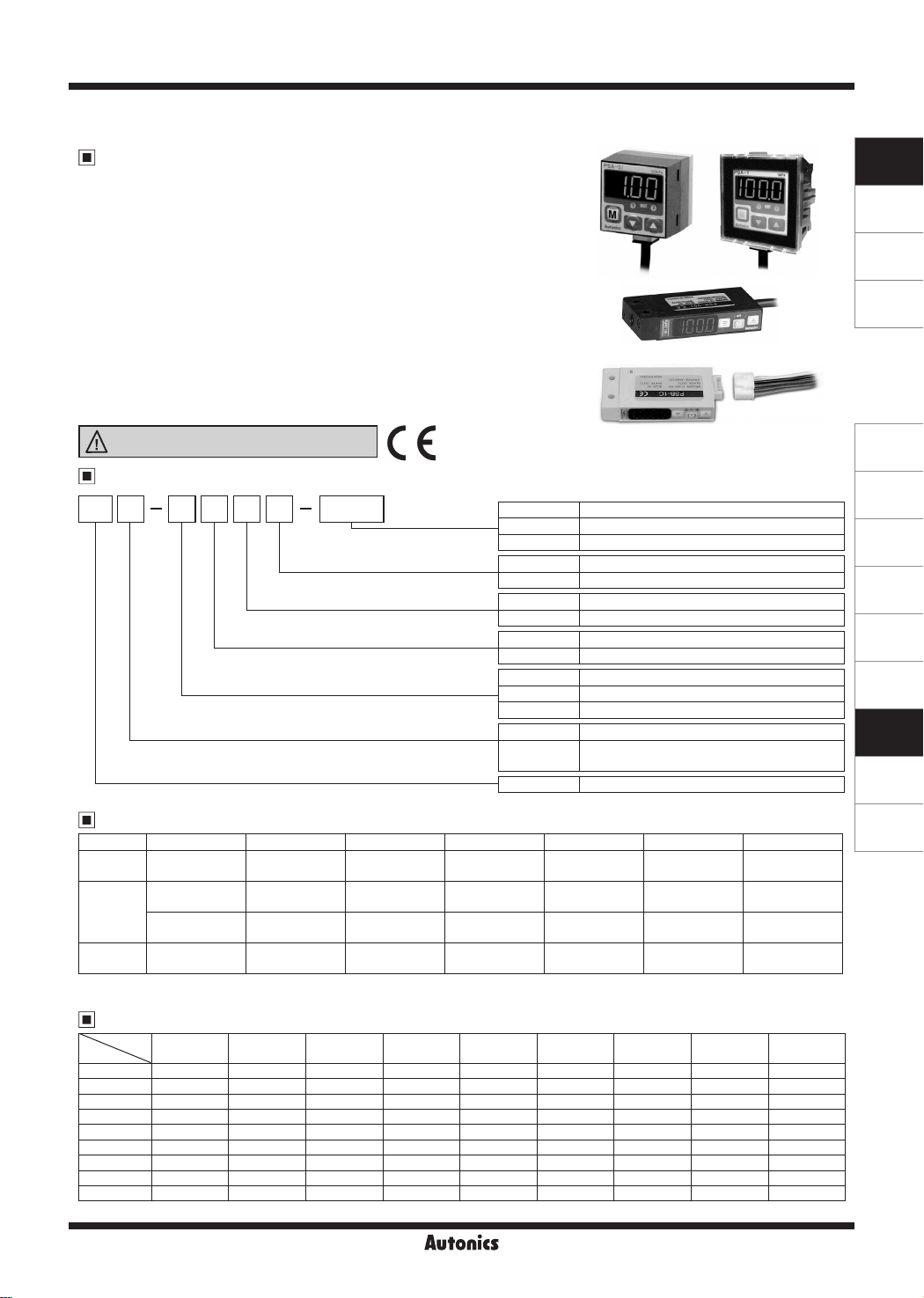
Ordering Information
PS 01 C PVA Rc1/8
L-~L-J___~
Output type
※
1
Cable
Pressure range
Pressure type
Appearance
Item
※
1: It is only applied to PSB Series.
Pressure port
Rc1/8 Standard (PSA Series)
NPT1/8 Option (PSA Series)
M5 Standard (PSB Series)
No mark NPN open collector output
P PNP open collector output
No mark Cable type
C Connector type
01 100kPa
1 1,000kPa
No mark Standard pressure
V Negative pressure
C Compound pressure
A Regular square (30×30mm)
B
PS Pressure Sensor
Rectangular (cable type: 10.4×54.2mm)
Pressure and Max. Pressure Display Range
Type kPa kgf/cm
Negative
pressure
Standard
pressure
Compound
pressure
※
( ) is Max. pressure display range.
※
For using a unit
0.0 to -101.3
(5.0 to -101.3)
0.0 to 100.0
(-5.0 to 110.0)
0 to 1000
(-50 to 1100)
-100.0 to 100.0
(-101.2 to 110.0)
, multiply display value by 100.
mmH₂O
2
0.000 to -1.033
(0.051 to -1.033)
0.000 to 1.020
(-0 051 to 1.122)
0.00 to 10.20
(-0 51 to 11.22)
-1.020 to 1.020
(-1 034 to 1.122)
bar psi mmHg inHg mmH2O
0.000 to -1.013
(0.05 to -1.013)
0.000 to 1.000
(-0.050 to 1.100)
0.00 to 10.00
(-0.50 to 11.00)
-1.000 to 1.000
(-1.012 to 1.100)
0.00 to -14.70
(0.74 to -14.70)
0.00 to 14.50
(-0.72 to 15.96)
0.0 to 145.0
(-7.2 to 159.6)
-14.50 to 14.50
(-14.70 to 15.96)
0 to -760
(38 to -760)
- - -
- - -
-750 to 750
(-760 to 824)
Pressure Conversion Chart
to
from
1Pa 1 0.001 0.000001 0.000010197 0.007501 0.101972 0.000145038 0.00001 0.0002953
----------
1kPa 1000 1 0.001 0.010197 7.500617 101.971626 0.145038 0.01 0.2953
1MPa 1000000 1000 1 10.197162 7500.61683 101971.626 145.038243 10 295.299875
1kgf/cm
1mmHg 133.322368 0.133322 0.000133 0.001359 1 13.595099 0.019337 0.001333 0.039370
1mmH
1psi 6894.733 6.89473 0.006895 0.070307 51.714752 703.016716 1 0.068947 2.036014
1bar 100000 100 0.100000 1.019716 750.062 10197.1626 14.503824 1 29.529988
1inHg 3386.388 3.386388 0.003386 0.034532 25.40022 345.315507 0.491156 0.033864 1
E.g .) For calcula ing 760mmHg as kPa : According to above chart, 1mmHg is 0.133322kPa, herefore 760mmHg will be 760×0.133322kPa=101 32472kPa.
Pa kPa MPa kgf/cm
2
98066.5 98.0665 0.098067 1 735.55924 10000.0005 14.223393 0.980665 28.959025
O 9.80665 0.009807
2
-
2
mmHg mmH2O psi bar inHg
0.000099 0.073556 1 0.00142 0.000098 0.002896
PSA Series
PSB Series
PSB Series
Connector type
(connector type: 10×52mm)
0.0 to -29.9
(1.5 to -29.9)
-29.5 to 29.5
(-29.8 to 32.6)
0.0 to -103.3
(5.2 to -103 3)
-102.0 to 102.0
(-103.4 to 112.2)
SENSORS
CONTROLLERS
MOTION DEVICES
SOFTWARE
(A)
Photoelectric
Sensors
(B)
Fiber Optic
Sensors
(C)
e-----
LiDAR
(D)
Door/Area
Sensors
(E)
Vision
Sensors
(F)
Proximity
Sensors
(G)
Pressure
Sensors
(H)
Rotary
Encoders
(I)
Connectors/
Connector Cables/
Sensor Distribution
Boxes/ Sockets
Autonics
G-35
PSA / PSB Series
Specifications
Pressure type
NPN open
collector output
※
1
Model
Rated pressure range 0.0 to -101.3kPa 0.0 to 100.0kPa 0.0 to 1,000kPa -100 0 to 100.0kPa
Display and set pressure range
Max. pressure range 2 times of rated pressure 1 5 times of rated pressure 2 times of rated pressure
Applied uid Air, Non-corrosive gas
Power supply 12-24VDCᜡ ±10% (ripple P-P : Max. 10%)
Current consumption Max. 50mA
Control output
Hysteresis
Repeat error ±0.2% F.S. ±1-digit ±0.2% F.S. ±2-digit
Response time Selectable 2.5ms, 5ms, 100ms, 500ms
Protection circuit Output short over current protection circuit
Analog output
Display digit 3½ -digit
Display method 7-segment LED
Min. display interval 1-digit (psi unit: 2-digit are fixed) 2-digit
Pressure unit
Display accuracy 0 to 50℃: Max. ±1% F.S., -10 to 0℃ : Max. ±2% F.S.
Environment
Vibra ion 1.5mm amplitude at frequency of 10 to 55Hz (for 1 min) in each X, Y, Z direction for 2 hours
Material
Protec ion structure IP40 (IEC standard)
Cable
Approval
Weight
※
1: '
※
2: In hysteresis output mode, detection dierence is variable.
※
3: The weight includes packaging. The weight in parenthesis in for unit only.
※
F.S.: Rated pressure.
※
There may be ±1-digit error in hysteresis by pressure unit calculation error.
※
The specication of pressure port is marked on the upper part of the case.
※
Environment resistance is rated at no freezing or condensa ion.
PNP open
collector output
※
2
Ambient temp. -10 to 50℃, storage: -20 to 60
Ambient humi. 35 to 85%RH, storage: 35 to 85%RH
Cable type Ø4mm, 5-wire, 2m (AWG24, Core diameter: 0.08mm, Number of cores: 40, Insulation out diameter: Ø1mm)
Connector type 5-wire, 3m (AWG24, Insulation out diameter: Ø1mm)
※
3
' is pressure port type. Please refer to the '
□
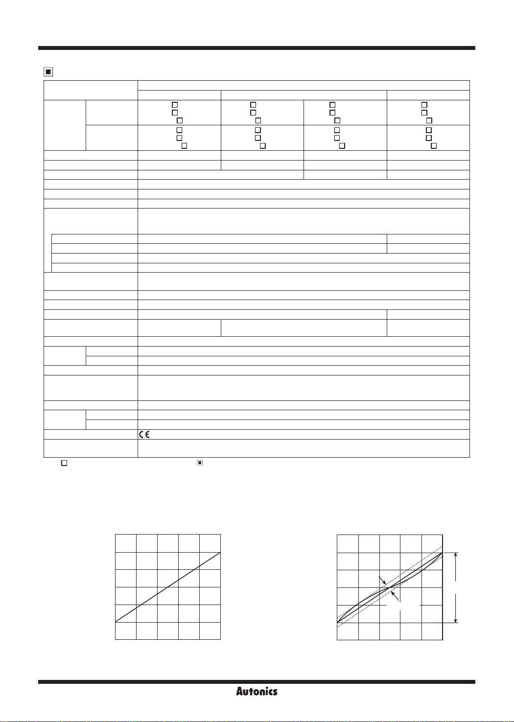
● Analog output voltage-Pressure characteristic ● Analog output voltage-Linear characteristic
PSA-01 PSA-01
Output
voltage
(V)
6
5
4
3
2
1
0
Gauge pressure
Negative pressure Standard pressure Compound pressure
PSA-V01-
PSB-V01PSB-V01C-
PSA-V01PPSB-V01PPSB-V01CP-
5.0 to -101.3kPa -5.0 to 110.0kPa -50 to 1,100kPa -101 2 to 110.0kPa
NPN or PNP open collector output
• Load voltage: Max. 30VDCᜡ • Load current: Max. 100mA
• Residual voltage - NPN: Max. 1VDCᜡ, PNP: Max. 2VDC
1-digit fixed (2-digit for psi unit) 2-digit fixed
• Output voltage: 1-5VDCᜡ ±2% F.S. • Zero-point: Within 1VDCᜡ ±2% F.S. • Span: Within 4VDCᜡ ±2% F.S.
• Linear: Within ±2% F.S. • Resolution: Approx. 1/200 • Output impedance: 1kΩ
kPa, kgf/cm
mmHg, mmH
• PSA
• PSB - Case, Pressure port, Cover: IX EF
• PSB-C - Case, Pressure port, Cover: IXEF
□
□
□ □ □
□ □ □ □
□ □ □ □
□ □
2
, bar, psi,
O, inHg
2
- Front, Rear case: Polycarbonate (insert glass), Pressure port: die-cast (Zn)
PSA-01-
□
PSB-01-
□
PSB-01CPSA-01P-
PSB-01PPSB-01CP-
kPa, kgf/cm
℃
2
, bar, psi
PSA-1-
□
PSB-1-
□
PSB-1CPSA-1P-
PSB-1PPSB-1CP-
□
PSA-C01PSB-C01PSB-C01C-
PSA-C01PPSB-C01PPSB-C01CP-
kPa, kgf/cm
mmHg, mmH
CE
• PSA: Approx. 200g (approx. 120g)
• PSB: Approx. 160g (approx. 70g) • PSB-C: Approx. 160g (approx. 70g)
Ordering Information'.
6
Output
voltage
(V)
5
V
,,v
/
/
V
/
40
20
60 80 100
Pressure (kPa)
4
3
2
1
0
20
±2% F.S.
60 80 100
40
Pressure (kPa)
□
□
□
□
2
, bar, psi,
O, inHg
2
Full
scale
G-36
Autonics

Compact, Digital Display Pressure Sensor
Dimensions
~
PSA Series
•
34
30
30
35.5
23
m
38.5
20
13
2-M3
20
18.4
9
13.4
8.5
m
II
Ø4, 2m
Sold separately (front cover (PSO-P01)) Sold separately (panel bracket (PSO-01)) Panel cut-out
•
Bracket A Bracket B
•
40
9.7
r--7
42
5.7
1
40
• •
40
28.2
30
40
n____n
25
20
14
6
20
4.2
30
PSB Series
•
Cable type
•
3-Ø3.2
20
14
6
Ø4.2
45
13
15
1.6
2-Ø3.4
4
Ø4, 2m
4.2
14
26
20
20
30
35
1.---------------.1
Connector type
•
A
423526
3
Ø4.2
6
3-Ø3.2
5
40
10.5
1111
20
25.8
1.6
22
4.5
※
A: Rc1/8 (standard),
A
NPT1/8 (option)
+0.5
36
0
□
( panel thickness:
□
0.8 to 3.5mm)
Connector cable 3m
(Accessory)
2-Ø3.2
(unit: mm)
SENSORS
CONTROLLERS
MOTION DEVICES
SOFTWARE
(A)
Photoelectric
Sensors
(B)
Fiber Optic
Sensors
(C)
LiDAR
(D)
Door/Area
Sensors
(E)
Vision
Sensors
(F)
Proximity
Sensors
(G)
Pressure
Sensors
(H)
Rotary
Encoders
(I)
Connectors/
Connector Cables/
Sensor Distribution
Boxes/ Sockets
25
12
2-M2
19
4
Sold separately (connector cable (PSO-C01))
•
10.3
Pressure port
M5
Tap dep h: 5
54.2
※
Ø4mm, 5-wire, 2m
( AWG24, core diameter: 0.08mm,
number of cores: 40, insulator
diameter: Ø1mm)
Autonics
12
25.5
2-M2
19
4
10
Pressure port
M5
Tap dep h: 5
52
G-37

PSA / PSB Series
Control Output Diagram (PSA/PSB)
● NPN open collector output type ● PNP open collector output type
1kΩ
Overcurrent
protection
Main circuit
Overcurrent
protection
※
There is no short-circuit protection in analog voltage output. Do not connect this output to power supply or capacitive load directly.
※
Please observe input impedance of connected equipment when use analog voltage output.
And be sure to check voltage drop caused by resistance of extended wire.
※Ifshort-circuitthecontroloutputterminalorsupplycurrentovertheratedspecication,controlsignalisabnormaldueto
thecurrentprotectioncircuit.
Unit Description
(PSA Series)
1
2
4
1. 3½digit LED display (red)
: Display sensing pressure, every setting value and display error.
2. 1 output indicator (red) : Output 1 is ON, LED will be ON.
3. 2 output indicator (PSA: red, PSB: green)
: Output 2 is ON,LED will be ON.
(Brown)+V
(Orange)Analog
voltage output
(Black)OUT1
(White)OUT2
(Blue)0V
56
Load
(PSB Series)
7
7 3
3
Load
1
+
12-24VDC
-
624
(Brown)+V
Overcurrent
protection
Overcurrent
protection
Main circuit
1kΩ
4. Mode key
: Parameter setting mode or preset setting mode,
save setting value.
5. Up key
: Set the setting value to lower step in preset setting
or pressure unit, output mode, response time,
analog output scale, key lock, peak hold value,
5
bottom hold value display in parameter setting.
6. Down key
: Set setting value to upper step in preset setting
or pressure unit, output mode, response time,
analog output scale, key lock, peak hold, bottom
hold display in parameter setting.
7. Range of rated pressure
: It is possible to change the pressure unit in PSA
Series. Please use dierent unit as label for your
application.
(Black)OUT1
(White)OUT2
(Orange)Analog
voltage output
(Blue)0V
Load
Load
+
-
12-24VDC
Setting (PSA/PSB)
Press key
00
over 3sec.
00
Press
over 3sec.
RUN mode
Press
over 1sec.
key
+ key
Parameter
setting
Preset value
setting
Peak hold
Zero-point
adjustment
Display
unit setting
ID►I l►I
Sensing level 1 setting
Peak hold Bottom hold
Zero-point adjustment
[
ST1, LO
Output operation
mode setting
]
I
Zero Point Adjustment (PSA/PSB)
1 2
1. In state of atmospheric pressure during RUN mode,
press key and key at the same time for over 1sec.
2. When the zero point adjustment is completed, it will
display )0 and return to RUN mode automatically.
※
Please execute zero point adjustment regularly.
G-38
I
►
►
I
Autonics
Response
time setting
Sensing level 2 setting
[
ST2, LO
I
Analog output scale
setting (1VDC)
I
►
I
]
※
If executing zero point adjustment when
external pressure has been applied,
be ashing. Please execute zero point again in
state of atmospheric pressure.
Analog output scale
setting (5VDC)
I
►
I
Key lock
setting
l►DI
will
ER1

Compact, Digital Display Pressure Sensor
Parameter Setting (PSA/PSB)
RUN mode
SENSORS
Press Key
over 3sec.
UNT
OUT
SPD
A-1
A-5
Display unit
setting
Output operation
mode setting
Response
time setting
Analog output
scale setting
(1VDC)
Analog output
scale setting
(5VDC)
UNT
and previously set unit will flash in turn every 0.5 sec.
or key to select the unit.
Press
(Press
key momentarily, the unit will be saved, hen move to the next mode.)
● Negative pressure, compound pressure:
9F MMHBAR PSI
2
(kPa)
(kgf/cm
(bar)
)
(psi)
(mmHg)
● Standard pressure:
~~
PA
~
~'---------------------------------------------------------------------------'
(kPa)
OUT
and previous output operation mode will f lash by turning on. (0.5sec)
Select the output operation mode with
(Press
9F BAR PSI
2
(bar)
)
(kgf/cm
key momentarily, the response time will be saved, then move to the next mode.)
(psi)
, Key.
(inHg)
※
For using mm
multiply display value
by 100.
H2OPA INH
(mmH
O)
2
unit,
H
₂O
F-1 F-6F-2 F-5F-3 F-4
SPD
and the previous response time will flash by turning on. (0.5sec)
Select the output operation mode with
(Press
key momentarily, the response time will be saved, then move to the next mode.)
~~«=Jd~
@5 %0 100 500
~~
~'-------------------------------------------------------------------------'
A-1
and the previous pressure will f lash by turning on. (0.5sec)
Set the pressure which will output 1VDC with
Allowable set ing range : Min. value of rated pressure ≤ [
(Press key momentarily, the selected pressure is set as 1VDC scales, then move to the next mode.)
A-5
and he previous pressure will flash by turning on. (0.5sec)
Set the pressure which will output 5VDC by
Allowable set ing range : [
(Press key momentarily, the selected pressure is set as 5VDC scales, then move to the next mode )
] +10% of rated pressure ≤ [
A-1
, Key.
~
-,
, Key.
, Key.
(unit : ms)
] ≤ 90% of rated pressure
A-1
]< Max. value of rated pressure
A-5
CONTROLLERS
MOTION DEVICES
SOFTWARE
(A)
Photoelectric
Sensors
(B)
Fiber Optic
Sensors
(C)
LiDAR
(D)
Door/Area
Sensors
(E)
Vision
Sensors
(F)
Proximity
Sensors
(G)
Pressure
Sensors
(H)
Rotary
Encoders
(I)
Connectors/
Connector Cables/
Sensor Distribution
Boxes/ Sockets
EY
and the previous key lock will flash by turning on (0 5sec)
Key Lock
EY
※
When advance to parameter setting mode and preset setting mode, it displays "Setting item" and "Previous setting value" by 0.5 sec.
turn. This display will stop by pressing
by 0.5sec. turn again.
※
※
key is pressed for 3sec. during set ing, it will return to RUN mode with memorizing on EEPROM. However, when there is any
When
key is untouched for 60sec., it turns to RUN mode with keeping the previous setting value not current setting value.
There is memory protec ion by EEPROM, but life cycle of EEPROM is 100,000 times.
f-'
Select key lock with
(Press
~~
※
•
(Enable to change
•
•
key momentarily, key lock is set, then move to the display unit setting mode )
LO
C
~ ~
~'---------------------------------------------------'
Key lock functions
LOC
: Disable to change preset value and parameter value
PaL
: Disable to change parameter setting/preset, zero point adjustment (Enable to check peak
hold and bottom hold, and to change
UNL
: Enable to change preset value and parameter value (Lock off)
or key (Display setting value), if any key is untouched for over 1 sec., it will display old value
, Key.
PaL UNL
f-'
EY
-:
mode only)
f-'
EY
mode)
Autonics
G-39

PSA / PSB Series
Preset Value Setting (PSA/PSB)
~
@
Hysteresis mode[ ] and independent 2 output mode[ , , ]
F-
I
F-3
F -
bl
F-5
@
....
RUN mode
※
ST1
setting range : Min. display pressure <
※
ST2
setting range : - Hysteresis mode: Min. display pressure ≤
- 2 independent output mode: Min. display pressure<
@
Automatic sensitivity setting mode[ ]
RUN mode
※
ST1
setting range : Min. display pressure
※
ST2
setting range :
@
Window comparison output mode[ ]
ST1
+ 1% of rated pressure
ST1
and previously set value
ST1
will flash in turn every 0.5 sec.
ST1
<
and previously set value
ST1
will flash in turn every 0 5 sec.
t
Press or Key
to select
value.
≤ Max. display pressure
After applying
into
ST1
Pressure port,
then press
Key.
≤ Max. display pressure
ST2
≤ Max. display pressure
<
F- 6
@
....
~ ~
set ing
ST1
ST2
ST1
<
ST2
will flash in turn every 0 5 sec.
ST2
≤ Max. display pressure
@
....
and previously set value
After applying
into
ST2
Pressure port,
than press
Key.
-
1% of rated pressure
@
....
and previously set value
ST2
will flash in turn every 0.5 sec.
t
Press or Key
~ ~
to select
ST2
value.
and previously set value
SET
will flash in turn every 0.5 sec.
Sensitivity will be automatically
Press
adjust the setting value between
SET
Adjustable range of set value:
Between
setting
.
SET
or key to fine-
ST1
ST1+ST2
=
ST1
RUN mode
RUN mode
and
.
ST2
2
and
.
ST2
RUN mode
and previously set value will
RUN mode
※
Low value setting range : Min. display pressure ≤
※
High value setting range : LO ≤ HI< Max. display pressure
LO
flash in turn every 0 5 sec.
Press or Key
to select LOsetting
value.
LO
≤ Max. display pressure
● If no key is touched for 60sec., it will return to RUN mode. [Automatic sensitivity setting mode[
and previously set value will
HI
flash in turn every 0 5 sec.
or Key
Press
to select HIsetting
value.
] is exception]
F 2
● When changing the display unit, preset value will be calculated according to the display unit.
● Whenever key touched one time, it is increased (decreased) as 1 digit (2 digits for psi unit and compound pressure) but it
will be continuously increasing (decreasing) by pressing , key constantly.
Peak Hold and Bottom Hold Check
1. Press key for over 3sec. in RUN mode.
PeH
2.
and memorized max. pressure (Negative pressure type is for max. negative pressure) will ash by turning on (0.5sec.)
then display peak hold value.
BoH
3.
and memorized min. pressure (Negative pressure type is for min. negative pressure) will ash by turning on (0.5sec.)
then display bottom hold value.
4. If pressing key one time shortly, memorized peak hold and bottom hold value will be removed then return to RUN mode.
※
When the peak hold and bottom hold value is over the max. display pressure value, it displays
displays
G-40
LLL
. Please remove peak hold and bottom hold value by using
Autonics
key.
HHH
On the opposite, it
,

Compact, Digital Display Pressure Sensor
Output Operation Mode (PSA/PSB)
1. Hysteresis mode [ ]
※
It can be set for pressure sensing level[
dierence[
※
ST1
: Min. display pressure
ST2
: Min. display pressure ≤
• OUT 1: When applying pressure is larger than
• OUT 2: When applying pressure is lower than
ST2
setting range
setting range
F-
I
] and sensing
ST1
].
≤ Max. display pressure
<
ST1
<
ST1
ST2
ST1
ST2
, it wil be ON.
, it will be ON.
OUT1
OUT2
Input
ST1
ST2
ON
OFF
ON
OFF
l
SENSORS
CONTROLLERS
Time
MOTION DEVICES
SOFTWARE
ST1
SET
and
]
value, it will
, it
ST2
ST1
and
OUT1
OUT2
ST2, ER3
Input
ST2
SET
ST1
ON
OFF
ON
OFF
will be displayed.
2. Automatic sensitivity setting mode [
※
This function is to set pressure sensing level to the proper
position automatically, it is set by received pressure from two
positions [
※
The sensing hysteresis xed to 1 digit (2 digits for psi unit and
ST1, ST2
compound type)
※
The pressure sensing level
calculation.
• OUT 1 : When applying pressure is larger than
be ON.
• OUT 2 : When applying pressure is between
will be ON.
Note
1) If it is not enough for dierence of sensing level between
SET
].
is shown in the following
[
]
SET
(
+
ST1
=
)
ST2
2
Please set again after applying enough pressure.
Note
2)
setting range: Min. display pressure ≤
ST1
setting range:
ST2
+1% of rated pressure ≤
ST1
ST1
≤ Max. display pressure -1% of rated pressure
≤ Max. display pressure
ST2
Note3) If ne adjustment for sensing level is required, adjust sensing level by , key.
(Adjustment range : Between
3. Independent 2 output mode [
※
and
ST1
range. One is for control, the other is for alarm or optional
control.
※
The sensing hysteresis xed to 1 digit (2 digits for psi unit and
can be set independently within display pressure
ST2
ST1
and
)
ST2
, , ]
Input
ST2
ST1
compound type)
※
settingrange
ST1
:Min.displaypressure≤
settingrange
ST2
:Min.displaypressure≤
●
Independent2outputmode[
•
OUT1:ItwillbeON,whenitisover
• OUT2:ItwillbeON,whenitisover
●
Independent2oppositemode[
•
OUT1:ItwillbeOFFwhenitisover
• OUT2:ItwillbeOFF,whenitisover
●
Independent2crossmode[
•
OUT1:ItwillbeOFFwhenitisunder
• OUT2:ItwillbeON,whenitisunder
≤Max.displaypressure
ST1
≤Max.displaypressure
ST2
]
F 3
F 5
F 4
]
.
ST1
.
ST2
]
.
ST1
.
ST2
.
ST1
.
ST2
ON
OUT1
OUT2
OUT1
OUT2
OUT1
OUT2
OFF
ON
OFF
ON
OFF
ON
OFF
ON
OFF
ON
OFF
F 3
F 4
F 5
Time
Time
(A)
Photoelectric
Sensors
(B)
Fiber Optic
Sensors
(C)
LiDAR
(D)
Door/Area
Sensors
(E)
Vision
Sensors
(F)
Proximity
Sensors
(G)
Pressure
Sensors
(H)
Rotary
Encoders
(I)
Connectors/
Connector Cables/
Sensor Distribution
Boxes/ Sockets
4. Window comparison output mode [ ]
※
It is able to set High limit value [HI], Low limit value [LO] of
F-6
pressure sensing level in this mode.
※
The sensing hysteresis xed to 1 digit (psi unit and compound
type 2 digits)
※
setting range
LO
: Min. display pressure ≤ LO< Max. display pressure
HIsetting range : LO≤ HI< Max. display pressure
• OUT 1 : It will be ON between high limit value[ HI] and low limit
value[LO]
• OUT 2 :It will be ON when it is over high limit value[ HI] and low
limit value[ LO].
Autonics
OUT1
OUT2
Input
HI
LO
ON
OFF
ON
OFF
Time
G-41

PSA / PSB Series
Functions (PSA/PSB)
~
@
Pressure unit change
PS -V01 (C) (P)/PS -C01 (C) (P) has 7 kinds of pressure
□ □
unit and PS
pressure unit.
Please select the proper unit for application.
• PS
□
kPa, kgf/cm², bar, psi, mmHg, inHg, mmH₂O
• PS
□
※
Whenusing
@
Output mode change
There are 6 kinds of control output modes in order to
provide the various detection. Select a mode for your proper
application.
• Hysteresis mode [
When variable hysteresis is required for pressure detection.
• Automatic sensitivity setting mode [
When it is required to set detecting sensitivity automatically
at proper position.
• Independent 2 output mode [
When it is required to detect pressure from two position
with one product.
• Window comparison output mode [
When is required to detect pressure in a certain range.
-01 (C) (P)/PS -1 (C) (P) has 4 kinds of
□ □
-V01 (C) (P), PS -C01 (C) (P) :
-01 (C) (P), PS -1 (C) (P) : kPa, kgf/cm², bar, psi
□
mmH₂O
□
multiplythedisplayvalueby100.
F- I
]
]
, , ]
]
@
Error display
Error display Description Troubleshooting
ER1
ER2
ER3
HHH
LLL
When external pressure is
input while adjusting zero
point
When overload is applied
on control output
When the setting value is
not matched with setting
condition
When applied pressure
exceeds High-limit of
display pressure range
When applied pressure
exceeds Low-limit of
display pressure range
Try again after
removing external
pressure
Remove overload
Check setting
conditions and set
proper setting values
Apply pressure within
display pressure range
Installation (PSA Series)
1. When installing pressure port, it is able to bring pressure
from 3 directions by changing the mounting direction of
the pressure port.
2. Basic spec of pressure port is Rc1/8 and option pressure
port is NPT1/8. Use general one-touch fitting.
Response time change
(chattering prevention)
It can prevent chattering of control output by changing
response time. It is able to set 4 kinds of response time (2.5,
5, 100, 500ms) and if the response is getting longer, the
sensing will be more stable by increasing the number of
digital filter.
Analog output scale setting
It is not fixed the analog output (1-5VDC) scale as the rated
pressure range but this is a function to change properly
for user's application. When the position[
output and the position [
pressure range of
A 1
] for 5VDC output are set, the
A 5
to
is to 1-5VDC analog output.
A 5
] for 1VDC
A 1
Key lock
This unit has 2 kinds of key lock function in order to prevent
wrong operation.
•
: All keys are locked, it is impossible to change any
L
o[
parameter setting/preset, zero point adjustment, peak
hold and bottom hold. (Enable to change
•
: It is impossible to change parameter setting/preset,
PR.l
zero point adjustment. (Enable to check peak hold and
bottom hold, and to change
•
: All keys are unlocked.
Unl
EY
mode).
EY
mode only).
Zero-point adjustment
This function is to set the display value of pressure at zero
when port is opened to atmospheric pressure.
Peak hold and bottom hold
This function is diagnosis malfunction of the system caused
by parasitic pressure or to check through memorizing the
max./min. pressure that occurred in the system.
3. Please use seal tape at port plug in order to prevent
pressure leak.
4. Please block another two pressure ports not used with
port plug.
Spring
washer
Port plug
Hexagon
wrench bolt
5. Please connect it by using spanner (13mm) at the metal
part in order not to overload on the body when connecting
one touch fitting.
13mm
spanner
~
Caution
The tightening torque of one touch tting should be max.
10N.m. If not, it may cause mechanical problem.
G-42
Autonics

Compact, Digital Display Pressure Sensor
--...
'
• '
·s.~
Spring
washer
\ &
"·,
Hexagon
wrench
bolt
6. PSA Series has 2 kinds
of brackets so it is able
to install it in two different
ways.
7. At first, please unscrew
hexagon wrench bolt and
assemble the bracket
on this unit by fixing the
hexagon wrench bolt.
Caution
~--.
-~J:,
~
·--
0
In this case, tightening torque of hexagon wrench
should be max. 3N.m. If not, it may cause mechanical
problem.
8. Bracket (PSO-01) and front protection cover (PSO-P01)
are sold separately. Please see the pictures for installation.
Panel bracket (PSO-01)
Body
(PSA)
Protection
cover
(s)
Bracket panel
Installation (PSB Series)
1. Pressure port is M5. Use general one touch fitting.
Body
O-Ring
Pressure port
Hexagon wrench bolt (M2×10)
One touch fitting
2. It is able to use it without the pressure port according to
environment. In this case O-Ring between pressure port
and its body should not be taken out in order to prevent
pressure leak.
Proper Usage
Caution
PSA, PSB Series is for sensing of non corrosive gas.
Do not use this product at corrosive gas or ammable
gas, etc.
• Please using this unit within the range of specification, if
applying pressure is larger than specification, it may not
be working properly due to damage.
• After supplying power, it takes 3 sec. to work.
• When using switching mode power supply, frame ground
(F.G.) terminal of power supply should be grounded.
Switching
mode
power supply
• It may cause malfunction by noise, when wiring with
power line or high voltage line.
• Do not insert any sharp or pointed object into pressure
port. It may cause mechanical problem due to sensor
damage.
• Do not use this unit with flammable gas, because this is
not an explosion proof structure.
• Be sure that this unit should not be contacted directly with
water, oil, thinner, etc.
• Wiring must be done with power off.
+
-
F.G.
SENSORS
CONTROLLERS
MOTION DEVICES
SOFTWARE
(A)
Photoelectric
Sensors
(B)
Fiber Optic
Sensors
(C)
LiDAR
(D)
Door/Area
Sensors
(E)
Vision
Sensors
(F)
Proximity
Sensors
(G)
Pressure
Sensors
(H)
Rotary
Encoders
(I)
Connectors/
Connector Cables/
Sensor Distribution
Boxes/ Sockets
※
Do not pull the cable with a tensile strength of 30N or over
3. Please connect it by using spanner (10mm) at pressure
port in order not to overload on the body when
connecting one touch fitting.
10mm
Spanner
Caution
The tightening torque of one touch tting and hexagon
wrench should be Max. 5N.m and 2N.m. It may cause
mechanical trouble. Please do not use spanner to
install as it may cause mechanical trouble.
Autonics
Accessory
● PSA/PSB
.
• Pressure unit label
±100kPa
±1 020㎏f/㎠-1.034㎏f㎠1.020㎏f/㎠10.20㎏f
±14.50㎰i -14.70㎰i 14 50㎰i 145 0㎰i
±1.000bar 1.013bar 1.000bar 10 00bar
±750㎜hg -760㎜hg ×10 ×10
±29 5inHg -299inHg ×100 ×100
±102.0㎜H
● Only for PSA Series
• Port plug • Bracket A • Bracket B
±101.3kPa
100kPa 1MPa
O -103.4㎜H2O ×1000 ×1000
2
DISPLAY UNIT LABEL
㎠
J
G-43
 Loading...