

PSAN Series
Compact, Digital Display Pressure Sensors
Features
● Pressure measurement of any gas, liquid or oil
(※except substances which may corrode stainless steel 316L)
● Auto shift function
: with change in the original pressure, the external input adjusts the
determined level to match the change in pressure
(only available in models with auto shift/hold function)
● High display resolutions - negative pressure: 0.1kPa
- standard pressure: 0.1kPa, 1kPa
- compound pressure: 0.1kPa
●
Hold function: hold current display value or control output
● Forced output control mode for device testing and
maintenance
● One-touch connector type for easy wiring and maintenance
● Analog output: voltage (1-5VDC), current (DC4-20mA)
● Zero-point adjustment function,
peak value monitoring function, chattering prevention function
Please read “Safety Considerations”
in the instruction manual before using.
(connector type) (cable type)
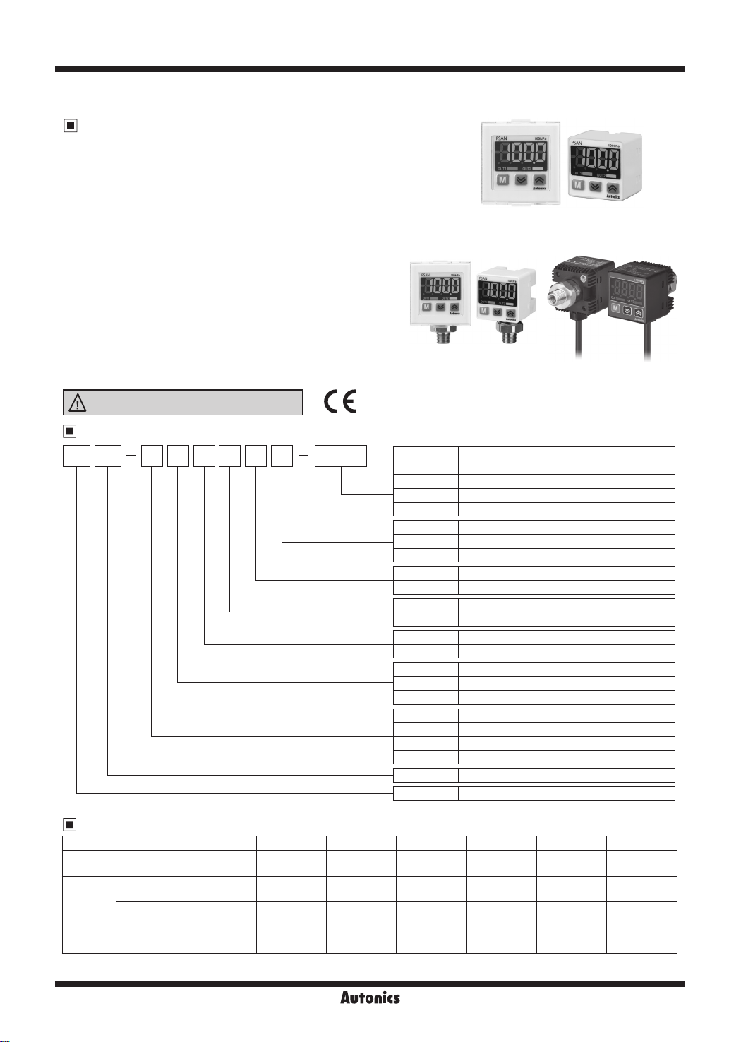
Ordering Information
PS AN V 01 C P V Rc1/8
Pressure
port
Option input/output
Control output
Cable
Pressure range
Pressure type
Applicable fluid
Appearance
Item
※
1: In case of using M5 port, use PSO-Z01 (M5 Gender) together.
R1/8 Standard (fluid type), Option (pneumatic type)
Rc1/8 Standard (pneumatic type)
※
NPT1/8 Option
1
7/16-20UNF Option (fluid type)
9/16-18UNF Option (fluid type)
V Voltage (1-5VDC) output
A Current (DC4-20mA) output
H Hold/Auto shift input
No mark NPN open collector output
P PNP open collector output
C Connector type
No mark Cable type
01 100kPa
1 1,000kPa
No mark Standard pressure
V Negative pressure
C Compound pressure
No mark Pneumatic type (gas)/rear port type
D Pneumatic type (gas)/bottom port type
L Fluid type (gas, liquid, oil)/bottom port type
B Fluid type (gas, liquid, oil)/rear port type
AN Regular square New type (30×30mm)
PS Pressure Sensor
Pressure and Max. Pressure Display Range
Type MPa kPa kgf/cm² bar psi mmHg inHg mmH₂O
Negative
pressure
Standard
pressure
Compound
pressure
※
( ) is max. pressure display range.
※
For using a unit
-
0 to 0.100
(-0.005 to 0.110)
0 to 1.000
(-0.050 to 1.100)
-
mmH
G-22
0.0 to -101.3
(5.0 to -101.3)
0.0 to 100.0
(-5.0 to 110.0)
0 to 1000
(-101.3 to 1100)
-101.3 to 100.0
(-101.3 to 110.0)
, multiply display value by 100.
₂O
0.000 to -1.033
(0.051 to -1.033)
0.000 to 1.020
(-0.051 to 1.122)
0.00 to 10.20
(-0.51 to 11.22)
-1.034 to 1.020
(-1.034 to 1.122)
0.000 to -1.013
(0.050 to -1.013)
0.000 to 1.000
(-0.050 to 1.100)
0.00 to 10.00
(-0.50 to 11.00)
-1.013 to 1.000
(-1.013 to 1.100)
0.00 to -14.70
(0.74 to -14.70)
0.00 to 14.50
(-0.72 to 15.96)
0.0 to 145.0
(-7.2 to 159.6)
-14.70 to 14.50
(-14.70 to 15.96)
0 to -760
(38.0 to -760.0)
- - -
- - -
-760 to 750
(-760.0 to 824.0)
Pneumatic type
Fluid type
0.0 to -29.9
(1.50 to -29.90)
-29.9 to 29.5
(-29.88 to 32.58)
PSAN-
0.0 to -103.3
(5.1 to -103.3)
-103.4 to 102.0
(-103.4 to 112.2)
B
Compact, Digital Display Pressure Sensor
-|Transparent setting guide|-
-|Transparent setting guide|-
Pressure Conversion Chart
to
from
1Pa 1 0.001 0.000001 0.000010197 0.007501 0.101972 0.000145038 0.00001 0.0002953
1kPa 1000 1 0.001 0.010197 7.500617 101.971626 0.145038 0.01 0.2953
1MPa 1000000 1000 1 10.197162 7500.61683 101971.626 145.038243 10 295.299875
1kgf/cm
1mmHg 133.322368 0.133322 0.000133 0.001359 1 13.595099 0.019337 0.001333 0.039370
1mmH
1psi 6894.733 6.89473 0.006895 0.070307 51.714752 703.0167161 1 0.068947 2.036014
1bar 100000 100 0.100000 1.019716 750.062 10197.1626 14.503824 1 29.529988
1inHg 3386.388 3.386388 0.003386 0.034532 25.40022 345.315507 0.491156 0.033864 1
Pa kPa MPa kgf/cm
2
98066.5 98.0665 0.098067 1 735.55924 10000.0005 14.223393 0.980665 28.959025
O 9.80665 0.009807 0.000099 0.073556 1 0.00142 0.000098 0.002896
2
E.g.) For calculating 760mmHg to kPa
: According to above chart, 1mmHg is 0.133322kPa, therefore 760mmHg will be 760×0.133322kPa=101.32472kPa.
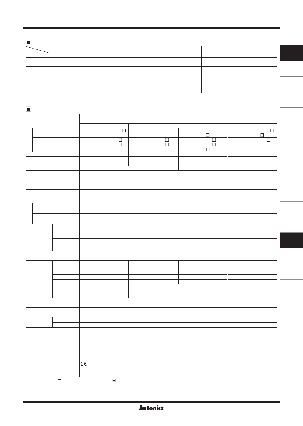
Specifications
Gauge pressure(In case of uid type, negative pressure, compound pressure, 1,000kPa/standard
Pressure type
Voltage
1
output
※
Current output
Hold/Auto
Model
shift input
Connector PSAN-(L/D)V01C(P)V-
Cable
Connector PSAN-(L)V01C(P)A-
Connector PSAN-(L)V01C(P)H-
Cable
Rated pressure range 0.0 to -101.3kPa 0.0 to 100.0kPa 0 to 1,000kPa -101.3 to 100.0kPa
Display pressure range 5.0 to -101.3kPa -5.0 to 110.0kPa -101.3 to 1,100kPa -101.3 to 110.0kPa
Min. display unit 0.1kPa 0.1kPa 1kPa 0.1kPa
Max. pressure range 2 times of rated pressure 1.5 times of rated pressure 2 times of rated pressure
Applied uid
Power supply 12V-24VDCᜡ ±10% (ripple P-P: Max. 10%)
Current consumption Max. 50mA (current output: max. 75mA)
Control output
※
Hysteresis
Repeat error ±0.2%F.S. ± Min. display interval
Response time
2
Protection circuit Output short over current protection circuit
Analog output
※
3
Voltage output
Current output
Display digit 4½-digit
Display method 7-segment LED Display
MPa
kPa 0.1 0.1 1 0.1
kgf/cm
Min. display
interval
bar 0.001 0.001 0.01 0.001
psi 0.01 0.01 0.1 0.02
mmHg 0.4
inHg 0.02 0.03
mmH₂O 0.1 0.1
Display accuracy 0 to 50℃: max. ±0.5% F.S., -10 to 0℃: max. ±1% F.S.
Insulation resistance Over 50MΩ (at 500VDC megger)
Dielectric strengtht 1000VAC 50/60Hz for 1 minute
Vibration 1.5mm amplitude at frequency of 10 to 55Hz (for 1 min) in each X, Y, Z direction for 2 hours
Environment
Ambient temp. -10 to 50℃, storage: -20 to 60
Ambient humi. 30 to 80%RH, storage: 30 to 80%RH
Protection structure Connector type: IP40 (IEC standard), Cable type: IP65 (IEC standard)
Material
Cable
Approval
※
4
Weight
※
1: For ' (L)', ' (P)', '
※
2: In hysteresis output mode, detection dierence is variable.
※
3: It is allowed to select one analog output type only.
※
4: The weight includes packaging. The weight in parenthesis in for unit only.
※
The unit is sealed structure. It is based on atmospheric pressure 101.3kPa.
5:
' of model name, please refer to '
pressure are sealed gauge pressure
Negative pressure Standard pressure Compound pressure
- -
- -
• Pneumatic type - Air, Non-corrosive gas
• Fluid type - Air, Non-corrosive gas and fluid that do not corrode Stainless steel 316L
NPN or PNP open collector output
• Load voltage: max. 30VDCᜡ • Load current: max. 100mA
• Residual voltage - NPN: max. 1VDCᜡ, PNP: max. 2VDC
Min. display interval
Selectable 2.5ms, 5ms, 100ms, 500ms, 1000ms
• Output voltage: 1-5VDCᜡ ±2% F.S. • Linear: Within ±1% F.S. • Output impedance: 1kΩ
• Zero point: Max. 1VDCᜡ ±2% F.S. • Span: Max. 4VDCᜡ ±2% F.S. •
• Resolution: Automatically changed to 1/1000 or 1/2000 by display unit
• Output current: DC4-20mA ±2% • Linear: Max. ±1% F.S. • Zero-point: Max. DC4mA ±2% F.S.
• Span: Max. DC16mA ±2% F.S. •
• Resolution: Automatically changed to 1/1000 or 1/2000 by display unit
-
2
0.001 0.001 0.01 0.001
• Pneumatic - Rear port type - Front, Rear case: Polycarbonate, Pressure port: Nickel Plated Brass
• Pneumatic - Bottom port type - Front case: Polycarbonate Rear case: Polybutylene Terephthalate + Glass
• Fluid type - Front case: Polycarbonate, Rear case: Polyamide 6, Pressure port: Stainless steel 316L
Ø4mm, 5-wire, 2m (connector type), 3m (cable type),
AWG24, Core diameter: 0.08mm, Number of cores: 40, Insulator out diameter: Ø1mm
• Pneumatic type - Rear port type: Approx. 165g (approx. 80g) • Pneumatic type - Bottom port type: Approx. 170g (approx. 85g)
• Fluid type - Connector type: Approx. 173g (approx. 88g) • Fluid type - Cable type: Approx. 167g (approx. 90g)
Ordering Information'.
2
mmHg mmH2O psi bar inHg
5
※
)
PSAN-(L/D)01C(P)V- PSAN-(L/D)1C(P)V- PSAN-(L/D)C01C(P)V-
PSAN-B1(P)V- PSAN-BC01(P)VPSAN-(L)01C(P)A- PSAN-(L)1C(P)A- PSAN-(L)C01C(P)APSAN-(L)01C(P)H- PSAN-(L)1C(P)H- PSAN-(L)C01C(P)H-
PSAN-B1(P)H- PSAN-BC01 (P)H-
Response time
: 70ms
0.001 0.001
Response time
: 50ms
-
0.8
-
℃
Fiber 15%, Pressure port: Nickel Plated Brass
※
F.S.: Rated pressure.
※
There may be ±1-digit error in hysteresis by pressure unit calculation error.
※
Environment resistance is rated at no freezing or condensation.
SENSORS
CONTROLLERS
MOTION DEVICES
SOFTWARE
(A)
Photoelectric
Sensors
(B)
Fiber Optic
Sensors
(C)
LiDAR
(D)
Door/Area
Sensors
(E)
Vision
Sensors
(F)
Proximity
Sensors
(G)
Pressure
Sensors
(H)
Rotary
Encoders
(I)
Connectors/
Connector Cables/
Sensor Distribution
Boxes/ Sockets
G-23
PSAN Series
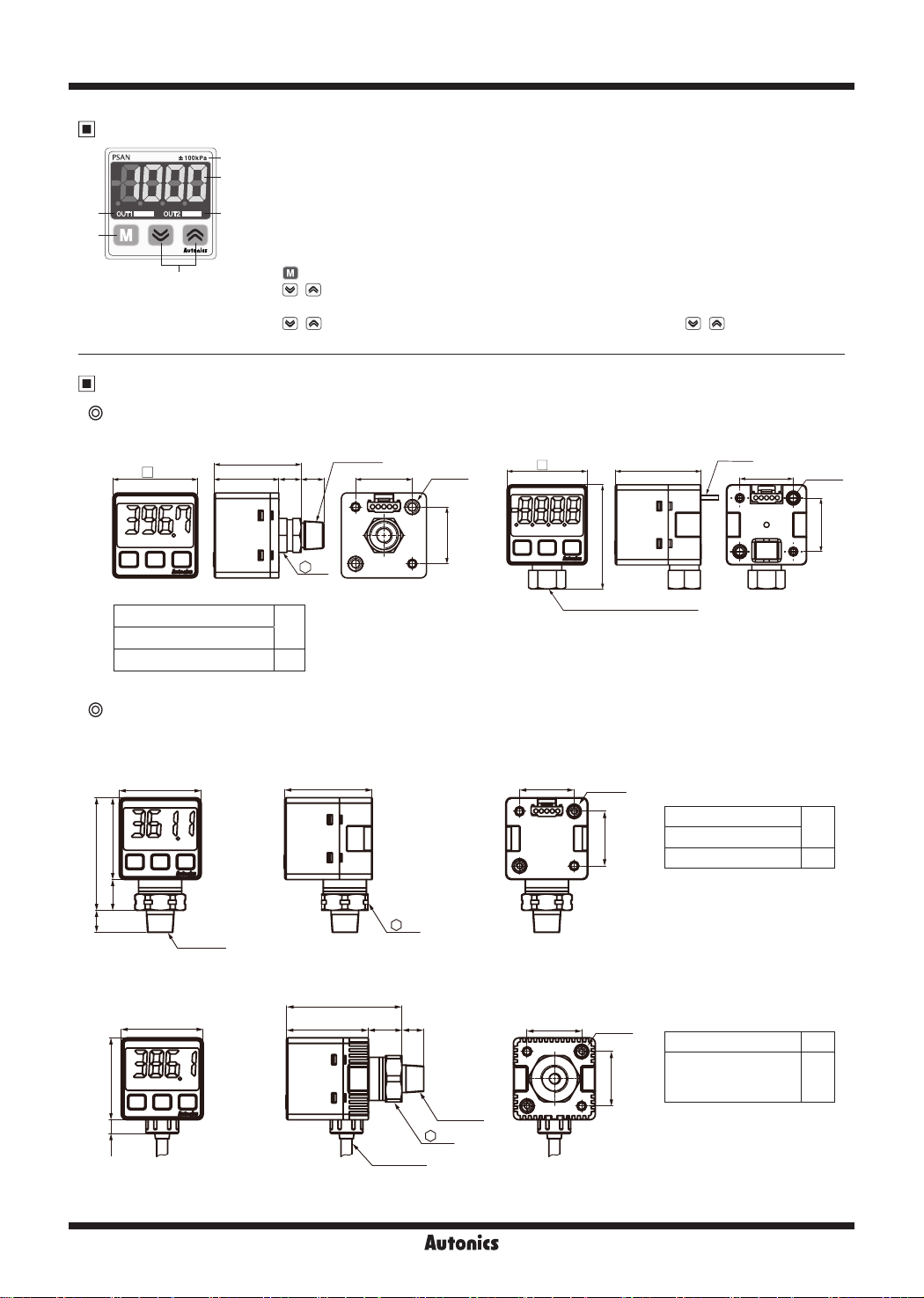
Unit Description
1. Range of rated pressure
1
2
3
5
4
6
Dimensions
Pneumatic type
1. Rear port type 2. Bottom port type
30
: It is possible to change the pressure unit in Pressure sensor.
Please attach component label which is t for specic indication unit.
2. 4-digit LED display (Red)
: Used to indicate measured pressure value, setting value and error message.
3. Output1 indicator (Red): Output1 is ON, LED will be ON.
4. Output2 indicator (Green): Output2 is ON, LED will be ON.
5.
key: Used to enter into Preset/Parameter setting mode and to save Setting mode.
,
6.
key: Used to set parameter and preset, peak value check mode, function setting or
output operation mode.
+
key : Used for zero point adjustment function by pressing + keys over 1 sec
simultaneously in RUN mode.
Inside
※
1
30.7
22.8 7.9 A
M5 Tap
20 2-M3
30
32
Cable
20
(unit: mm)
2-M3
※
A
Rc1/8 model (standard)
NPT1/8 model
R1/8 model
Fluid type
1. Connector type
30
30
41.3
11.3
A
2. Cable type
30
5.1
Inside
M5 Tap
30
20
12
※
1: Only for R1/8 and NPT1/8 models
39
Rc1/8(Standard), NPT1/8
20
0
8
32
12.3 B
Ø4, 3m
17
Inside
M5 Tap
17
※
1
※
42.3
30
20
2-M3
20
20
2
2-M3
20
※
A
R1/8 model (standard)
NPT1/8 model
7/16-20UNF model
※
1: Only for R1/8 model,
NPT1/8 model
※
B
R1/8 model (standard)
9/16-18UNF model
(metal gasket sealing
method)
※
2: Only for R1/8 model
8
11
8
15.4
G-24
Compact, Digital Display Pressure Sensor
-|Transparent setting guide|-
-|Transparent setting guide|-
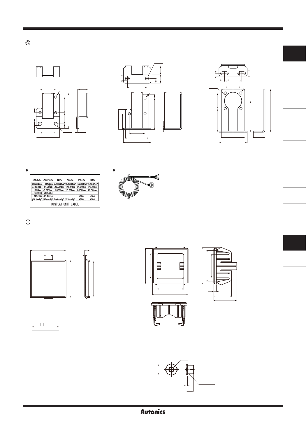
Accessory
● Bracket A ● Bracket C ● Bracket B
Ø4.2
1111
6
25
20
3-Ø3.2
14
6
Ø4.2
20
4.2
30
※
Bracket A/B:
Bracket C:
Pressure unit label Connector cable (PSO-C01)
Pneumatic type, fluid type (
Fluid type (
20
45
14
6
13
15
1.6
cable type)
4.2
14
26
20
20
30
35
connector type)
3-Ø3.2
5
40
1.6
※
Sold separately
● Front cover (PSO-P01)
40
9.7
42
5.7
1
40
● Panel bracket (PSO-B02/B03)
40
28.2
3.5
5.8
22
Ø22
20
30
Ø4mm, 5-wire, 2m
( AWG24, core diameter: 0.08mm,
number of cores: 40,
insulator diameter: Ø1mm)
423526
30
40
3
20
25.8
22
20
30
36
4.2
4-Ø3.2
40
(unit: mm)
55
15
SENSORS
CONTROLLERS
MOTION DEVICES
SOFTWARE
(A)
Photoelectric
Sensors
(B)
Fiber Optic
Sensors
(C)
LiDAR
(D)
Door/Area
Sensors
(E)
Vision
Sensors
(F)
Proximity
Sensors
(G)
Pressure
Sensors
(H)
Rotary
Encoders
(I)
Connectors/
Connector Cables/
Sensor Distribution
Boxes/ Sockets
● Panel cut-out
+0.5
36
0
(panel thickness 0.8 to 3.5mm)
※
PSO-B02 (white): Pneumatic type, Fluid type (connector type)
PSO-B03 (black): Fluid type (cable type)
● M5 gender (PSO-Z01)
M5
12
R1/8 or
1.6
NPT1/8
8.1
G-25

PSAN Series
Control Output Diagram
Voltage (1-5VDC) output type (PSAN-
Current (DC4-20mA) output type (PSAN-
V-
A-
● NPN open collector output type ● PNP open collector output type
(Brown) +V
(Black) OUT1
Over current
protection
circuit
Over current
protection
circuit
Main circuit
1kΩ
※
In case of analog voltage output type models short-circuit protection is not embodied. (
Do not connect of power source or capacitive load directly.
※
Be careful with input impedance of connecting devices when using analog voltage output type models.
※
Be careful with voltage drop due to cable resistance when extending sensor cable.
(White) OUT2
(Orange) Analog output
voltage/current
(Blue) 0V
Hold/Auto shift input (PSAN-
Load
Load
12-24VDC
H-
)
● NPN open collector output type ● PNP open collector output type
(Brown) +V
Load
Load
12-24VDC
Over current
protection
circuit
Over current
protection
circuit
Main circuit
(Black) OUT1
(White) OUT2
(Orange) Hold/
Auto shift input
(Blue) 0V
Over current
protection
circuit
Over current
protection
circuit
Main circuit
1kΩ
Over current
protection
circuit
Over current
protection
circuit
Main circuit
)
)
(Brown) +V
(Black) OUT1
(White) OUT2
(Orange) Analog output
voltage/current
(Blue)0V
: For voltage output type only.)
(Brown) +V
(Black) OUT1
(White) OUT2
(Orange) Hold/
Auto shift input
(Blue) 0V
12-24VDC
Load
Load
12-24VDC
Load
Load
If short-circuit the control output terminal or supply current over the rated specication, control signal is abnormal due to the current
※
protection circuit
Analog Output Characteristic
● Analog output voltage and current
- Pressure characteristic
Output
PSAN-01 PSAN-01
voltage
(V)
6
5
4
3
2
1
0
20 40 60 80 100
Pressure (kPa)
24
20
16
12
8
4
0
Output
current
(mA)
● Analog output voltage and current
- Linear characteristic
Output
6
voltage
(V)
5
4
3
2
1
0
20 40
±1% F.S.
60 80 100
Pressure (kPa)
Output
24
current
20
16
12
8
4
0
Setting
Press key
over 3sec
RUN mode
Press
over 3sec
Press
keys over 1sec
key
+
Parameter
setting
Preset value
setting
Forced output
control mode
setting
Peak hold
Zero-point
adjustment
Pressure
unit setting
Detection level 1 setting (out1) Detection level 2 setting (out2)
Output operation
mode setting
Output
type setting
Response
time setting
Analog output scale and
Hold/Auto Shift input setting
The forced output control mode is applied by pressing key after selecting forced output control mode
[
] in output operation mode [
fOUT
control mode' '
High peak
value check
Output operation mode'
Low peak
value check
] parameter. For more detailed information, refer to '● Forced output
OUtM
Auto shift input setting
(In case of Hold/Auto shift input type model)
Zero-point adjustment
(mA)
Full
scale
Key lock
setting
G-26

Compact, Digital Display Pressure Sensor
-|Transparent setting guide|-
-|Transparent setting guide|-
Zero Point Adjustment
1 2
SENSORS
CONTROLLERS
Press
over 1sec
※
1. In state of atmospheric pressure during RUN mode,
press key and key at the same time for over
1sec.
2. When the zero-point adjustment is complete, it will
)0
display
※
Please execute zero-point adjustment regularly.
and return to RUN mode automatically.
ERR1
will ash while you execute zero
point adjustment in the condition that external
pressure exists.
Please execute zero-point adjustment again in
state of atmospheric pressure without external
pressure.
Parameter Setting
1. It is able to set pressure unit, display resolution, output operation mode, output type, Response time, analog output
scale, Hold/Auto shift and key lock setting in parameter setting mode.
2. If the key lock is set (lock1 or lock2), unlock the key lock before setting parameters. (Refer to Key Lock setting below.)
RUN mode
Press
key over
3sec
Press key
over 3sec
UNIT
OUtM
Pressure unit
setting
Output operation
mode setting
UNIT
and previously set unit will flash in turn every 0.5 sec
or key to select the unit.
Press
(Press
key for 1 sec to save selected unit and move to next mode.)
● Negative pressure, compound pressure:
2
(kPa)
(kgf/cm
(bar)
)
(psi)
(mmHg)
● Standard pressure:
MPA KPA PSIKGF BAR
2
(kPa) (MPa)
OUtM
and previously set output operation mode will f lash in turn every 0.5 sec
Press
or key to select output operation mode.
(Press
key for 1 sec to save selected output operation mode and move to next mode.)
(kgf/cm
(bar)
)
(psi)
H2OKPA INHGKGF MMHGBAR PSI
(mmH
(inHg)
※
For using mm
multiply display value
by 100.
O)
2
unit,
H
₂O
MOTION DEVICES
SOFTWARE
(A)
Photoelectric
Sensors
(B)
Fiber Optic
Sensors
(C)
LiDAR
(D)
Door/Area
Sensors
(E)
Vision
Sensors
(F)
Proximity
Sensors
(G)
Pressure
Sensors
(H)
Rotary
Encoders
(I)
Connectors/
Connector Cables/
Sensor Distribution
Boxes/ Sockets
HYsM WIN HY-W AUTO fOUT
NoNC
NoNC
Output setting
and previously set output operation mode will f lash in turn every 0.5 sec
Press
or key to select output type.
(Press key for 1 sec to save selected output t ype and move to next mode.)
1O2O 1O2C 1C2O 1C2C
SPD
SPD
Response time
setting
and previously set output operation mode will f lash in turn every 0.5 sec
or key to select
Press
(Press key for 1 sec to save selected
@5 %0 100 500 1000
Response time
Response time
.
and move to next mode.)
(unit: ms)
G-27

PSAN Series
Voltage (1-5VDC) output type
(PSAN-
※
1
A-1V A-04 D-IN
※
2
A-5V A-20 ShOT
1V scale setting
5V scale setting
※
A-1V
1:
Press
Setting range: Min. rated pressure ≤ [
(Press key for 1 sec to save selected pressure value as a scale value for 1V and 4mA and move to next mode.)
※
A-5V
2:
Press
Setting range:[
(Press key for 1 sec to save selected pressure value as a scale value for 5V and 20mA and move to next mode.)
※
D-IN
3:
(Press key for 1 sec to save selected function and move to next mode.)
● Select external input function ● Select the control output for Auto shift function
V- )
※
※
(voltage output)/
or key to set analog output scale value for 1V and 4mA.
(voltage output)/
, Key to set analog output scale value for 5V and 20mA.
A-1V, A-04
and previously set control function will flash in turn every 0.5 sec Press
HOLD SHFT
LOCK
LOCK
Key Lock
will flash in turn with previous setting parameter. Press
(Press key for 1 sec to save selected lock setting. Then, it will return to pressure unit setting mode.)
Current (DC4-20mA) output type
(PSAN-
1
2
A-04
A-20
4mA scale setting
20mA scale setting
(current output)and previously set pressure value will flash in turn every 0.5 sec
A-1V, A-04
(current output) and previously set pressure value will flash in turn every 0.5 sec
]+10% of rated pressure ≤ [
A- )
※
] ≤ 90% of rated pressure
A-20
A-SV
,
OUT1 ALLOUT2
※
Refer to '
in ' Functions' for more details
Hold/Auto shift input setting'
Hold/Auto shift input type
(PSAN-
3
] ≤ Max. rated pressure
, key to select key lock setting.
Select external input function
Select the control output for
Auto shift function
, key to select external function.
H- )
OFFLOC1 LOC2
※
When pressing
there is no additional key operation within 60 sec while setting, current set value is not valid and previous set value will remain.
※
All settings are saved regardless of power failure. Make sure that this unit has a limited write life cycle (100,000 times).
key for 3 sec in the middle of parameter setting, current setting value will be saved and it will return to RUN mode. If
Preset Setting
Hysteresis mode [
RUN mode
Press or Key
to select
setting value.
※
ST1
setting range : Min. display pressure <
※
HYS1
setting range : Min. display pressure ≤
※
ST2
setting range : Min. display pressure
※
HYS2
setting range : Min. display pressure ≤
]
HYsMHYsM
and previously
ST1
set value will flash in
turn every 0.5 sec
ST1
HYS1
set value will flash in
turn every 0.5 sec
Press or key
HYS1
to select
setting value.
ST1
≤ Max. display pressure
HYS1
ST1
<
ST2
<
Max. display pressure
≤
HYS2
ST2
<
and previously
and previously
ST2
set value will flash in
turn every 0.5 sec
Press or key
ST2
to select
setting value.
and previously
HYS2
set value will flash in
turn every 0.5 sec
Press or key
HYS2
to select
setting value.
RUN mode
G-28

Compact, Digital Display Pressure Sensor
-|Transparent setting guide|-
-|Transparent setting guide|-
Window comparison output mode [
and previously
RUN mode
※
LO-1
setting range: Min. display pressure ≤
※
HI-1
setting range
※
LO-2
setting range: Min. display pressure ≤
※
HI-2
setting range
※
The minimum display interval for hysteresis is fixed to 1.
LO-1
set value will flash in
turn every 0.5 sec
Press
to select
setting value.
:
+ (3
LO-1
×min. display interval
:
+ (3
LO-2
×min. display interval
or Key
LO-1
Press or Key
to select
setting value.
LO-1
LO-2
]
WINWIN
and previously
HI-1
set value will flash in
turn every 0.5 sec
HI-1
≤
Max. display pressure
) ≤
≤
HI-1
≤
Max. display pressure
) ≤
Max. display pressure
≤
HI-2
Max. display pressure
Hysteresis-Window comparison output mode [
RUN mode
and previously
ST1
set value will flash in
turn every 0.5 sec
and previously
HYS1
set value will flash in
turn every 0.5 sec
LO-2
set value will flash in
turn every 0.5 sec
Press or Key
LO-2
to select
setting value.
- (3
×min. display interval
- (3
×min. display interval
]
HY-WHY-W
and previously
LOW
set value will flash in
turn every 0.5 sec
and previously
and previously
HI-2
set value will flash in
turn every 0.5 sec
Press or Key
HI-2
to select
setting value.
)
)
and previously
HIGH
set value will flash in
turn every 0.5 sec
RUN mode
RUN mode
SENSORS
CONTROLLERS
MOTION DEVICES
SOFTWARE
(A)
Photoelectric
Sensors
(B)
Fiber Optic
Sensors
(C)
LiDAR
(D)
Door/Area
Sensors
(E)
Vision
Sensors
Press
or Key
ST1
to select
setting value.
※
ST1
setting range : Min. display pressure
※
HYS1
setting range : Min. display pressure ≤
※
LOW
setting range : Min. display pressure ≤
※
HIGH
setting range : Low value + (3×min. display interval) ≤
※
In case
HYS1
ST1
and
have the same setting values, it will have the minimum display unit as a hysteresis.
Automatic sensitivity setting mode [
Press
Key
and previously
RUN mode
※
setting range : Min. display pressure
ST1
※
setting range :
ST2
※
If certain detection level difference is not ensured, or setting conditions are not met,
setting mode. Check all setting conditions and set proper setting values.
ST2
ST1
set value will flash in
turn every 0.5 sec
Press
or Key
ST1
to select
setting value.
+ 1% of rated pressure
ST1
Press or Key
to select
setting value.
ST1
<
HYS1
LOW
HYS1
≤ Max. display pressure
ST1
<
≤ Max. display pressure - (3×min. display interval)
HIGH
AUTOAUTO
]
Press
Key
and previously
ST2
set value will flash in
turn every 0.5 sec
Press or Key
ST2
to select
setting value.
≤ Max. display pressure - 1% of rated pressure
<
ST1
≤ Max. display pressure
<
ST2
Press or Key
to select
setting value.
≤ Max. display pressure
Press or Key
to select
setting value.
LOW
Press
Key
and previously
SET
set value will flash in
turn every 0.5 sec
Sensitivity will be automatically
Press
value between
SET
SET
message will flash three times and return to
ERR3
Press or Key
HIGH
to select
setting value.
RUN mode
or key to fine-adjust the setting
ST1
ST2
and
.
+
ST2
ST1
=
2
SET
.
(F)
Proximity
Sensors
(G)
Pressure
Sensors
(H)
Rotary
Encoders
(I)
Connectors/
Connector Cables/
Sensor Distribution
Boxes/ Sockets
G-29

PSAN Series
Forced output control mode [
If forced output control mode
is selected, pressure value is
displayed only.
(No output will be provided.)
Control output 1 ON Control output 1 OFF
Control output 2 ON Control output 2 OFF
※
When there is no additional key operation within 60 sec while
setting, it returns to Run mode (Except for force output mode).
Previously set values remain.
※
In case of changing output operation mode, no preset values
will be initialized. Instead, previous output operation settings will
become the preset values.
※
When using the forced output function, Hold/Auto shift function is
not available to use in Hold/Auto shift model.
※
When changing pressure display unit, resolution, and Hold Auto
shift input function, preset values will be initialized as shown on
the next table. (When changing pressure display unit, preset
value will be automatically switched to changed pressure unit.)
]
fOUTfOUT
Present pressure value and
fOUT
will flash in turn every 0.5 sec
● Factory default
Negative
Output
pressure
mode
0.0 to -101.3
ST1
:-50.0
HYS1
ST2
HYS2
LO-1
HI-1
LO-2
HI-2
ST1
HYS1
LOW
HIGH
ST1
ST2
SET
:0.0
:-50.0
:0.0
:0.0
:-50.0
:0.0
:-50.0
:-50.0
:0.0
:0.0
:-50.0
:0.0
:-50.0
:-25.0
HYS.M
WIN
HY-W
AUTO
Standard
pressure
0.0 to 100.0
ST1
:50.0
HYS1
:0.0
ST2
:50.0
HYS2
:0.0
LO-1
:0.0
HI-1
:50.0
LO-2
:0.0
HI-2
:50.0
ST1
:50.0
HYS1
:0.0
LOW
:0.0
HIGH
:50.0
ST1
:0.0
ST2
:50.0
SET
:25.0
Standard
pressure
0 to 1,000
ST1
:500
HYS1
:0
ST2
:500
HYS2
:0
LO-1
:0
HI-1
:500
LO-2
:0
HI-2
:500
ST1
:500
HYS1
:0
LOW
:500
HIGH
:0
ST1
:0
ST2
:500
SET
:250
(unit: kPa)
Compound
pressure
-101.3 to 100.0
ST1
:50.0
HYS1
:-50.0
ST2
:50.0
HYS2
:-50.0
LO-1
:-50.0
HI-1
:50.0
LO-2
:-50.0
HI-2
:50.0
ST1
:50.0
HYS1
:-50.0
LOW
:-50.0
HIGH
:50.0
ST1
:-50.0
ST2
:50.0
SET
:0.0
High Peak/Low Peak Function and Auto Shift Reference Pressure Check/Change
It will return to RUN
mode after previously
set Auto shift reference
pressure is removed.
Auto shift reference
pressure value will
flash every 0.5 sec
or key
Press
to select set value
Key
Press
for over 3 sec
RUN mode
※
1: Displayed only when
※
If there is no Auto shift input, "0" will be displayed. (Refer to '
D-IN
is set to
Retained maximum
pressure value will
flash every 0.5 sec
HHHH
"
" will flash if retained
maximum pressure value
is above the upper limit of
rated pressure.
(For negative pressure type,
LLLL
"
" will flash)
SHFT
(PSAN-
G-30
+
Press
keys over 1sec
Remove the
retained minimum
pressure value.
LLLL
"
minimum pressure value
exceeds low-limit of rated
pressure.
( For negative pressure type,
HHHH
"
H- models only)
High Peak / Low Peak Hold' in ' Functions' for more details.)
Press
+ keys over 1sec
Press
keys over 1sec
Remove the
retained minimum
pressure value.
Retained minimum
pressure value will
flash every 0.5 sec
" will flash if retained
" will flash)
+
※
1

Compact, Digital Display Pressure Sensor
-|Transparent setting guide|-
-|Transparent setting guide|-
Output Operation Mode
1. Hysteresis mode [
It is able to set certain value for pressure detection level
ST1, ST2
[
OUT1 N.O.
ST1/ HYS1
OUT1 N.C.
ST1/ HYS1
OUT2 N.O.
ST2/ HYS2
OUT2 N.C.
ST2/ HYS2
] and hysteresis [
h
ST2
HYS2
h
ST1
HYS1
ON
OFF
ON
OFF
ON
OFF
ON
OFF
] 2. Window comparison output mode [
HYsMHYsM
HYS1, HYS2
].
Time
Time
Time
Time
Time
①
It is able to set the range for high [
] limit of pressure detection level when it is required
LO-2
HI-1, HI-2
to detect pressure at a certain range.
②
Detection hysteresis is fixed to min. display range.
Pressure
OUT1 N.O.
LO-1/ HI-1
OUT1 N.C.
LO-1/ HI-1
OUT2 N.O.
LO-2/ HI-2
OUT2 N.C.
LO-2/ HI-2
HI-2
LO-2
HI-1
LO-1
ON
OFF
ON
OFF
ON
OFF
ON
OFF
※
1
※
1
※
1
※
1
※
: Min. display range
1
], low [
Time
Time
Time
Time
Time
WINWIN
LO-1
]
,
SENSORS
CONTROLLERS
MOTION DEVICES
SOFTWARE
(A)
Photoelectric
Sensors
(B)
Fiber Optic
Sensors
Time
Time
Time
Time
Time
HY-WHY-W
LOW
]
4. Automatic sensitivity setting mode [
①
This function is to set pressure detection level to the
proper position automatically. It is set by applied
,
OUtN
pressure from two positions [
②
Detection hysteresis is fixed to min. display range.
③
The pressure detection level[
following calculation.
Pressure
ST2
SET
ST1
SET
SET
ON
OFF
ON
OFF
ON
OFF
ON
OFF
fOUT
OUT1 N.O.
OUT1 N.C.
OUT2 N.O.
ST1/ ST2
OUT2 N.C.
ST1/ ST2
' is changed to '
※
1
SET
ST1+ST2
= (
※
1
※
1
', forced output control mode is
3. Hysteresis-window comparison output mode [
①
It is available to set hysteresis mode and window
comparison output mode when both hysteresis mode
ST1, ST2
[
HIGH
②
Detection hysteresis is fixed to min. display range.
OUT1 N.O.
ST1/ HYS1
OUT1 N.C.
ST1/ HYS1
OUT2 N.O.
LOW/ HIGH
OUT2 N.C.
LOW/ HIGH
5. Forced output control mode [
①
Used to display pressure with forcibly holding comparing output OFF regardless of setting value.
②
In parameter setting, if output operation mode setting '
] and window comparison output mode [
] are necessary.
Pressure
HIGH
LOW
ST1
HYS1
ON
OFF
ON
OFF
ON
OFF
ON
OFF
※
1
※
1
※
1
fOUTfOUT
: Min. display range
]
operated.
③
Output 1, 2 can be ON/OFF manually by pressing
Present pressure value
Display
will be displayed.
Displays PV and forced
output mode alternatively
, key while the forced output control mode is applied.
Present pressure value
will be displayed.
ST1, ST2
SET
SET
)/2
=
AUTOAUTO
].
] is shown in the
+ )
(
2
※
: Min. display range
1
Time
Time
Time
Time
Time
]
(C)
LiDAR
(D)
Door/Area
Sensors
(E)
Vision
Sensors
(F)
Proximity
Sensors
(G)
Pressure
Sensors
(H)
Rotary
Encoders
(I)
Connectors/
Connector Cables/
Sensor Distribution
Boxes/ Sockets
Output 1
Output 2
ON
OFF
ON
OFF
Time
Time
G-31

PSAN Series
Functions
Pressure unit change
PSAN-V01C (P) and PSAN-C01C (P) has 7 kinds of
pressure unit, PSAN-01C (P) and PSAN-1C (P) has
5 kinds of pressure unit. Please select the proper unit for
application.
• PSAN-V01C (P), PSAN-C01C (P)
: kPa, kgf/cm², bar, psi, mmHg, inHg, mmH2O
• PSAN-01C (P), PSAN-1C (P) : MPa, kPa, kgf/cm², bar, psi
※
When using mmH
Output mode change
There are 5 kinds of control output mode in order to realize
the various pressure detection.
• Hysteresis mode [
When needed to change hysteresis for detecting pressure.
• Window comparison output mode [
When needed to detect pressure in certain area.
• Hysteresis - Window comparison output mode [
When both hysteresis mode and window comparison
output mode are required.
• Automatic sensitivity setting mode [
When needed to set detection sensitivity automatically at
proper position.
• Forced output control mode [
When needed to display pressure with remaining
comparison output OFF regardless of setting value.
Control output change
Type of control output for Out1 and Out2 can be able to
set Normally Open or Normally Closed.
※
Note that Normally Open and Normally Closed provide
opposite output.
OUT1 output OUT2 output Parameter setting value
Normally Open Normally Open
Normally Open Normally Closed
Normally Closed Normally Open
Normally Closed Normally Closed
Response time change
(chattering prevention)
It can prevent chattering of control output by changing
Response time
(2.5ms, 5ms, 100ms, 500ms, 1000ms) and if the
time
is getting longer, the detection will be more stable by
increasing the number.
Analog output scale setting
• Analog voltage output scale setting
The scale function for analog output voltage (1-5VDC) is
not fixed to the rated pressure range. It can be changed for
User's application. Analog output voltage range will be fixed
to 1-5VDC within the pressure range from pressure point of
1VDC output [
A-SV
[
].
• Analog current output scale setting
The scale for analog output Current (DC4-20mA) is not
fixed to the rated pressure range. It can be changed for
User's application. Analog output voltage will be fixed to
DC4-20mA within the rated pressure range from pressure
point of 4mA output [
A-20
output [
G-32
O unit, multiply display value by 100.
2
]
HYsMHYsM
WINWIN
]
fOUTfOUT
1O2O
1O2C
1C2O
1C2C
. It is able to set 5 kinds of
A-1V
] to pressure point of 5VDC output
A-04
] to pressure point of 20mA
].
]
HY-WHY-W
]
AUTOAUTO
Response time
Response
Hold/Auto shift input setting
• Hold
A function to hold present pressure value and control
output at the time of hold signal input.
※
Present pressure value and Hold message will ash in
turn every 0.5 sec while Hold function is set. Make sure
that Hold function is not able to execute while forced
output mode is executed.
Control output timing chart
▶
When Hold signal is applied in Hysteresis mode, refer to
"
Control output diagram".
Pressure
E.g.)
]
OUT1 N.O.
ST1/ HYS1
OUT1 N.C.
ST1/ HYS1
OUT2 N.O.
ST2/ HYS2
OUT2 N.C.
ST2/ HYS2
HOLD
signal line
(Yellow)
OUT1 N.O.
ST1/ HYS1
OUT1 N.C.
ST1/ HYS1
OUT2 N.O.
ST2/ HYS2
OUT2 N.C.
ST2/ HYS2
※
[
] and present pressure value will ash in turn
HOLD
every 0.5 sec while Hold signal is applied.
• Auto shift
A function to use the measured pressure at the moment of
auto shift input as a reference pressure in order to correct
the set point values of control output when initial pressure
changes.
※
Reference pressure is xed to atmospheric pressure
(0.0kPa) when Auto shift function is not used.
※
ShIN
(Auto shift compensation value) will be reset to 0
when changing control output or preset values.
※
Auto shift function will not be executed if "
LLLL
"
•
•
" error occurs or if forced output mode is set.
: Reference pressure change through setting.
ShOT
: Changed reference will be applied to control output
OUT1
1 only.
•
: Changed reference will be applied to control output
OUT2
2 only.
•
: Changed reference will be applied to both control
ALL
output 1 and control output 2.
ST2
HYS2
ST1
HYS1
ON
OFF
ON
OFF
ON
OFF
ON
OFF
High
Low
ON
OFF
ON
OFF
ON
OFF
ON
OFF
h
h
Flashing
in turn every
0.5 sec
HHHH
Time
Time
Time
Time
Time
Time
Time
Time
Time
" or
When
there
is no
HOLD
input
signal
When
there is
HOLD
input
signal

Compact, Digital Display Pressure Sensor
-|Transparent setting guide|-
-|Transparent setting guide|-
When Auto shift is used
▶
When Auto shift input signal remains at low level more than
1ms, the measured pressure at this point will be saved as
a reference value to make correct judgment regardless of
pressure changes. Corrected preset pressure value will be
applied after 7.5ms.
Measured reference pressure value will be saved in [
Flashing twice when
input Auto shift signal
Auto shift
input
Switch
output
response
※
When Auto shift function is used, the possible set
Min. 1ms
Min. 7.5ms
(Switch output
when Auto shift signal is input)
Response time
Preset point value will be
corrected by Auto shift input.
pressure range will be wider than rated set pressure
range.
※
The possible set pressure range for Auto shift type
models.
Pressure
type
Vacuum
pressure
Vacuum
pressure
Compound
pressure
※
If the set point value corrected by auto shift input
Set pressure range
-101.3kPa to 5.0kPa -101.3kPa to 101.3kPa
-5.0kPa to 110.0kPa -110.0kPa to 110.0kPa
-50.0kPa to 1100kPa -1100kPa to 1100kPa
-101.3kPa to 110.0kPa -101.3kPa to 110.0kPa
Possible set pressure range
for Auto shift type models
exceeds set pressure range,an error message will flash
three times and corrected value is not saved.
-HH-
→[
] displayed when the set point value corrected by
Auto shift input is above the upper limit of set pressure
range.
-LL-
→ [
] displayed when the set point value corrected
by Auto shift input is below the lower limit of set pressure
range.
Example of Auto shift
▶
< When Auto shift is not used >
Increase of primary
Pressure
ST1
HYS1
OUT
OFF
Normal primary
h
ON
pressure
Drop of primary
pressure
pressure
ShIN
Time
Time
Time
Time
Time
< When Auto shift is used >
Increase of primary
Pressure
ST1
HYS1
Normal primary
pressure
Drop of primary
pressure
pressure
].
ON
OUT
OFF
Auto shift input
Reference pressure =
Atmospheric pressure
(0.0kPa)
Correction set value:
Correction set value:
※
ShIN
Reference pressure ≤
Atmospheric pressure
is the reference pressure set by Auto shift input.
(0.0kPa)
=
ST1
HYS1
Auto shift input
Reference pressure ≥
Atmospheric pressure
ST1+ ShIN
=
+
HYS1
ShIN
Key lock
The key lock function prevents key operations so that
conditions set in each mode.
•
: All keys are locked; therefore it is not available to
LOC1
change parameter settings, preset value, zero adjustment,
High/Low peak check, and
data initialization. (Lock
ShIN
setting change is available)
•
: Partially locked status; therefore it is not available
LOC2
to change parameter settings only (Lock setting change is
available). Other settings are still available.
•
: All of the setting is available, all keys are unlocked. to
OFF
set detection sensitivity automatically at proper position.
Zero-point adjustment
The key lock function prevents key operations so that
conditions set in each mode.
The zero-point adjustment function forcibly sets the
pressure value to "zero" when the pressure port is opened
to atmospheric pressure. When the zero adjustment is
applied, analog output [Voltage or Current] is changed by
this function.
(Press
+ keys over 1 sec in RUN mode.)
High peak / Low peak hold
This function is to diagnosis malfunction of the system
caused by parasitic pressure or to check through memorizing
the max./min. pressure occurred from the system.
Error
Description Troubleshooting
display
When external pressure is
input while adjusting zero
ERR1
point
When overload is applied
ERR2
on control output
When setting condition is
not met in Auto sensitivity
ERR3
setting mode
When applied pressure
exceeds Low-limit of
LLLL
display pressure range
When applied pressure
exceeds High-limit of
HHHH
display pressure range
-HH-
Auto shift correction error
-LL_
-HO_
Try again after removing
external pressure
Remove overload
Check setting conditions
and set proper setting
values
Apply pressure within
display pressure range
Set the corrected setting
value within setting
pressure range.
(0.0kPa)
Time
Time
SENSORS
CONTROLLERS
MOTION DEVICES
SOFTWARE
(A)
Photoelectric
Sensors
(B)
Fiber Optic
Sensors
(C)
LiDAR
(D)
Door/Area
Sensors
(E)
Vision
Sensors
(F)
Proximity
Sensors
(G)
Pressure
Sensors
(H)
Rotary
Encoders
(I)
Connectors/
Connector Cables/
Sensor Distribution
Boxes/ Sockets
G-33

PSAN Series
Installation Proper Usage
1. Pressure port is divided as standard and option
specication. Therefore, be sure that to use commercially
available one touch tting.
2. Please connect it by using spanner (pneumatic type
12mm, uid type 17mm) at the metal part in order not to
overload on the body when connecting one touch tting.
12mm
Spanner
<Pneumatic type>
<Fluid type>
17mm
Spanner
Caution
PSAN Series is for sensing of non corrosive gas.
Do not use this product at corrosive gas or ammable
gas, etc.
• Please using this unit within the range of specification, if
applying pressure is larger than specification, it may not
be working properly due to damage.
• After supplying power, it takes 3 sec to work.
• When using switching mode power supply, frame ground
(F.G.) terminal of power supply should be grounded.
Caution
The tightening torque of one touch tting should be
max.10N.m. If not, it may cause mechanical problem.
3. Two dierent brackets are provided for pneumatic type
and three dierent brackets are provided for uid type.
Select proper one with considering your application
environments.
4. At rst, please unscrew hexagon wrench bolt and
assemble the bracket on this unit by xing hexagon the
wrench bolt.
Connector type Connector type Cable type
Bracket B
Hexagon wrench blot
(M3×6)
Bracket A
Caution
Spring washer
Bracket C
In this case, tightening torque of hexagon wrench
should be max. 3N.m. If not, it may cause mechanical
problem.
5. Panel bracket (PSO-B02/B03) and front cover
(PSO- P01) are sold separately. Please see the pictures
for installation.
Switching
Mode
Power
Supply
+
-
F.G.
• It may cause malfunction by noise, when wiring with
power line or high voltage line.
• Do not insert any sharp or pointed object into pressure
port. It may cause mechanical problem due to sensor
damage.
• Do not use this unit with flammable gas, because this is
not an explosion proof structure.
• Be sure that this unit should not be contacted directly with
water, oil, thinner, etc.
• Wiring must be done with power off.
Panel bracket
(PSO-B02/B03)
Front cover
(PSO-P01)
Mounting panel
(panel thickness: 0.8 to 3.5mm)
※
Do not pull the cable with a tensile strength of 30N or
over.
G-34
Body (PSAN)
 Loading...