

Autonics PA10 Series Catalog Page
PA10 Series
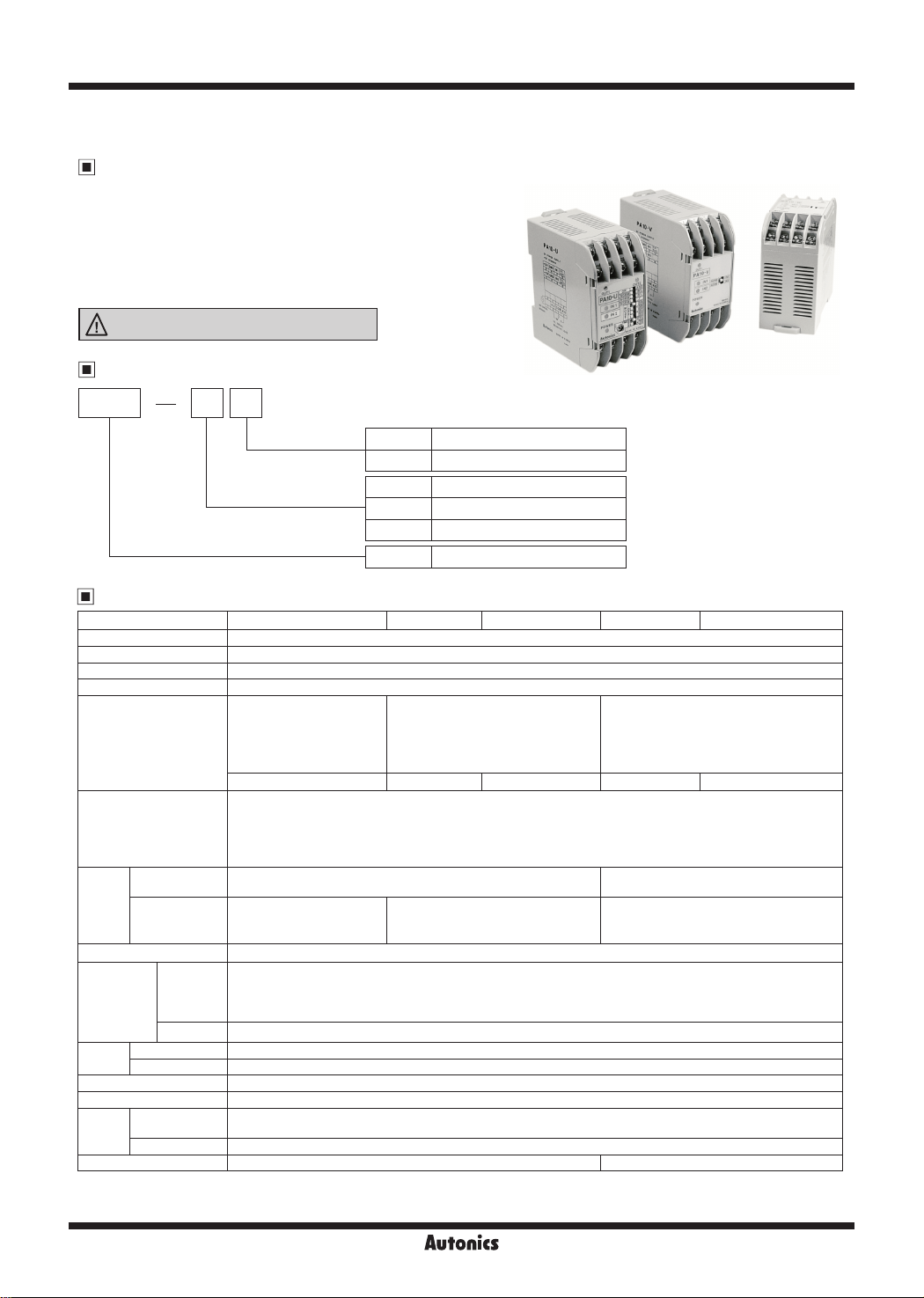
Multifunctional Sensor Controller
Features
● 13 kinds of various operation modes selected by DIP switches
● High speed input response
● Flip-op mode for level control
● Multifunctional unit with timer mode
● DIN rail, Mounting to panel
● Wide range of power supply (100-240VAC 50/60Hz)
Please read “Safety Considerations” in operation
manual before using.
Ordering Information
PA10 U
:-
11.u
~
I
~~~.
'·::-
,\
""
11
,
No mark NPN input
P PNP input
U High function controller
V General purpose controller
W 2-channel controller
PA10 Power amplier
Item
9
Function
Input
Specifications
Model PA10-U PA10-V PA10-VP PA10-W PA10-WP
Power supply 100-240VACᜠ 50/60Hz
Allowable operation voltage 90 to 110% of rated voltage
Power consumption Max. 10VA (condo ion:12VDCᜡ/200mA resistive load)
Power for external sensor 12VDCᜡ ±10% Approx. 200mA
Input (IN1) (IN2)
Input type
Contact output OUT: 250VACᜠ 3A, 30VDCᜡ 3A (resistive load)
Output
Solid-state
output
Response time Relay output: Max. 10ms, Transistor output: Max. 0.05ms
Time setting
function by
each mode
Only for
※
PA10-U
Relay
life cycle
Dielectric strength 2000VAC 50/60Hz for 1 minute
Insulation resistance Over 100MΩ (at 500VDC megger)
Environment
Unit weight Approx. 150g Approx. 160g
※
If the load is connected over 200mA at the sensor output, it may cause mechanical trouble.
※
Environment resistance is rated at no freezing or condensation.
Have
None • Normal Mode • Flip-Flop Mode • Encoder (mode 9 to 11)
Mechanical Min. 10,000,000 operations
Electrical Min. 100,000 operations (250VAC 3A resistive load)
Ambient
temperature
Ambient humidity 35 to 85%RH, storage: 35 to 85%RH
Selectable NORM/INV.
Selectable OR/AND
operation for IN1, IN2 input.
Selection function for IN2
derivative action.
NPN input type NPN input type PNP input type NPN input type PNP input type
● PA10-U (no-voltage input) Impedance at short-circuit: Max. 680Ω,
● PA10-V/PA10-W (no-voltage input) Impedance at short-circuit: Max. 300Ω,
● PA10-VP/PA10-WP (voltage input) Input impedance: 5.6kkΩ, "H" level voltage 5-30VDCᜡ, "L" level voltage: 0-2VDC
O.C. OUT1/O.C. OUT2
: NPN open collector output
Max. 30VDCᜡ 100mA
• ON Delay Mode
• One-Shot Delay Mode
• Flicker One-Shot Mode
• High-Speed Detection Mode
-10 to 55℃, storage: -25 to 60
Selectable NORM/INV.
Operation for IN1, IN2 AND.
Residual voltage at short-circuit: Max. 0 8V, Impedance at open: Min. 100kΩ
Residual voltage at short-circuit: Max. 2V, Impedance at open: Min. 100kΩ
O.C. OUT: NPN open collector output
Max. 30VDCᜡ 100mA
• OFF Delay Mode
• Flicker Mode
• Low-Speed Detection Mode
• ON/OFF Delay Mode
℃
Selectable NORM/INV.
Operation for IN1, IN2 AND.
OUT1, OUT2
: 250VACᜠ 3A, 30VDCᜡ 3A (resis ive load)
-
O-2
Autonics
Multifunctional Sensor Controller
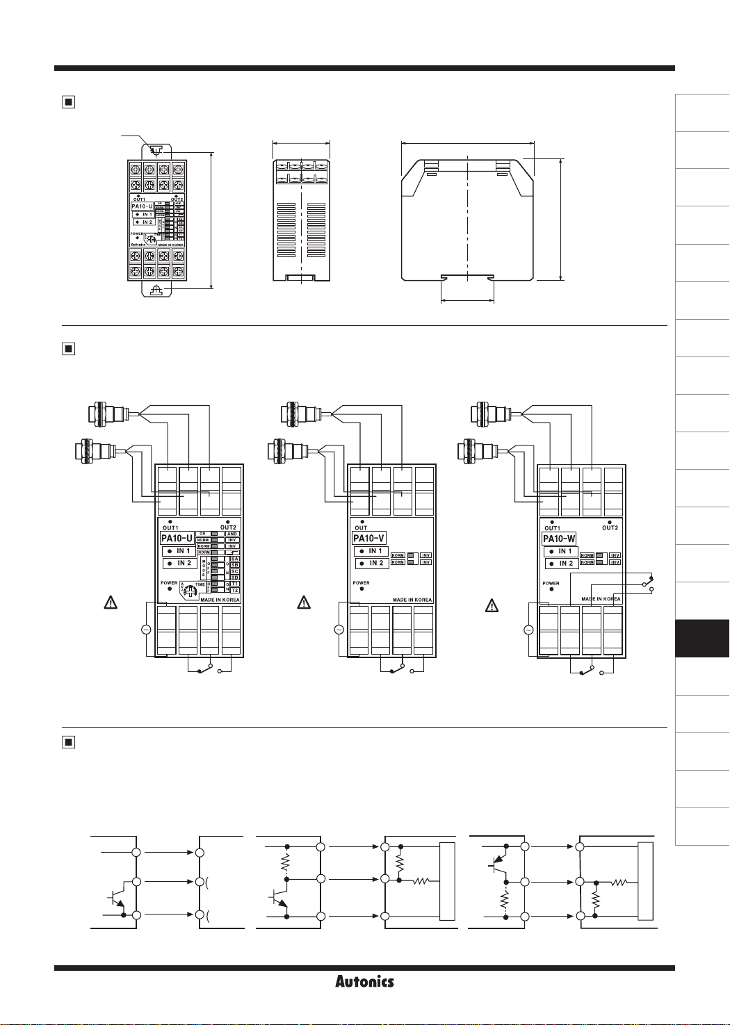
Dimensions
Ø5
Connections
● PA10-U
Brown Brown BrownBlue Blue BlueBlack Black Black
+12 GND IN1
9 10 11 12
Black
Blue
Brown
+12 GND IN2
13 14 15 16
SOURCE
100-240VAC
50/60Hz
5 6 7 8
NC COM NO
1 2 3 4
CONTACT OUT:
250VAC 3A, 30VDC 3A
RESISTIVE LOAD
Input Connections
● PA10-U
NPN open
collector
output
type sensor
+12V
IN1,IN2
0V
±0.5
94
● PA10-V/PA10-VP
O·C
OUT1
O·C
OUT2
● PA10-V / PA10-W
Sensor
controller
⑨, ⑬
⑪
⑮
⑩
⑭
NPN open collector type
& NPN universal output
type sensor
IN1
IN2
38
I
=I=
==
§II§
==
==
==
==
§1'§
==
==
I
SOURCE
100-240VAC
50/60Hz
82
35.5
● PA10-W/PA10-WP
+12 GND IN1
9 10 11 12
Black
Blue
Brown
+12 GND IN2
13 14 15 16
•
OUT
IPA10-VI
~[!Qfil!]EJlmNJ
~~g_Jm!YJ
POWER
•
5 6 7 8
NC COM NO
1 2 3 4
CONTACT OUT:
250VAC 3A, 30VDC 3A
RESISTIVE LOAD
O·C
OUT1
SOURCE
100-240VAC
50/60Hz
● PA10-VP / PA10-WP
Sensor
controller
+12V
1.8
9.4
kΩ
kΩ
IN1,IN2
0V 0V
PNP open collector type
& PNP universal output
type sensor
Main circuit
76
+12 GND IN1
9 10 11 12
Black
Blue
Brown
+12 GND IN2
13 14 15 16
• •
OUT1
IPA10-WI
~liiiiiiillEflIBill
~[HQRM]g_J[Iloo
5 6 7 8
NC2
NC1
1 2 3 4
CONTACT OUT1,OUT2:
250VAC 3A, 30VDC 3A
RESISTIVE LOAD
+12V
IN1,IN2
COM2
COM1
(unit: mm)
OUT2
NO2
NO1
OUT1
Sensor
controller
5.4
kΩ
5.6
kΩ
OUT2
(A)
Photoelectric
Sensors
(B)
Fiber
Optic
Sensors
(C)
Door/Area
Sensors
(D)
Proximity
Sensors
(E)
Pressure
Sensors
(F)
Rotary
Encoders
(G)
Connectors/
Connector Cables/
Sensor Distribution
Boxes/Sockets
(H)
Temperature
Controllers
(I)
SSRs / Power
Controllers
(J)
Counters
(K)
Timers
(L)
Panel
Meters
(M)
Tacho /
Speed / Pulse
Meters
(N)
Display
Units
(O)
Sensor
Controllers
(P)
Switching
Mode Power
Supplies
(Q)
Stepper Motors
& Drivers
& Controllers
(R)
Graphic/
Logic
Panels
(S)
Field
Network
Devices
(T)
Software
Main circuit
Autonics
O-3
PA10 Series
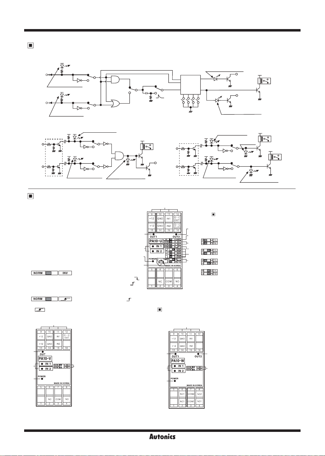
Function Diagram
●PA10-U
+5V
IN1
N1 input indicator
+5V
N2
N2 input indicator
NORM
NORM
INV
INV
AND
OR
NORM
(Derivative)
MODE
SW
Control
box
OUT1 output indicator
OUT1
OUT2 output indicator
O.C.
O.C.
OUT2
+12v
OUT
●PA10-V ●PA10-VP ● PA10-W ● PA10-WP
IN1
IN2
※
Add when it is PNP input
IN1 input indicator
+12v
NORM
+12v
IN2 input indicator
INV
NORM
INV
+12v
OUT output indicator
OUT
O.C.
OUT
IN1
N2
※
Add when it is PNP input
N1 input indicator
+12v
+12v
N2 input indicator
Unit Description
● PA10-U
1. Power indicator:
LED is turned on when AC power applied
2. Output1 indicator:
Indication of output 1 operation status
3. Output2 indicator:
Indication of output 2 operation status
4. Sensor input indicator
Indicates sensor input signal
(LED is turned on when sensor input is Low)
5. AND/OR selection switch:
Select "AND" or "OR" for IN1, IN2 Input
6. Selection switch of sensor input signal
I NORM
ID
● NORM: LED is turned on when input signal is low. ( )
● INV: LED is turned on when input signal is high. ( )
7. Derivative action selection of IN2 input signal
(OR/AND selection switch: AND)
1 NORM
ID
● NORM: IN2 input signal is operating as reverse turn function
● : IN2 Derivative action of IN2 input signal. (※Refer to O-8, Applicatio of derivative operation,)
(Reverse function of input signal)
II~
(When input signal is high ( ) it is effective signal.)
11
_s--1
_f"
_f"
2
4
1
10
t...
● PA10-V/PA10-VP
5
3
•
OUT
IPA10-VI
2
~~
-
~
0 •
POWER
1
•
Power
Power
※
When IN1, IN2 input signal is AND, OUT will work.
1. Power indicator:
LED is turned on when AC power applied
2. Output indicator:
Indicates output operation
3. Sensor input indicator:
● PA10-V: Indicates sensor input signal
(LED turns on when sensor input is Low)
● PA10-VP: Indicates sensor input signal
( LED turns on when sensor input is
4
High)
4. Selection switch of sensor input signal
● NORM: When sensor input signal is Low,
● INV: When sensor input signal is High, it
5. Terminal block
it is vaild signal.
is valid signal.
11
Power
Power
● PA10-W/PA10-WP
2
4
POWER
1
•
Power
NC1
NC1
Power
8~
※
IN1, IN2 operates
individually.
8. Selection switch for operation mode:
9. Selection switch of time range and max. input
3
5
6
7
8
9
10. Timer adjuster
11. Terminal block
6
COM2
71
COM1
2 3 4
Operation mode> in next page.
See <
frequency: It is the switch to select time range
(1 to 7 mode) or allowable input frequency (9 to 11
mode).
@lc::JlolwJ
IE]~
@IC::ClolwJ
1m::c~
Adjust time as same as the range of 9.
1. Power indicator:
LED is turned on when AC power applied
2. Output1 indicator:
Indication of output 1 operation status
3. Output2 indicator:
Indication of output 2 operation status
4. Sensor input indicator:
3
● PA10-W: lndicates sensor input signal
5
Low)
● PA10-WP: Indicates sensor input signal
5. Selection switch of sensor input signal
N02
N01
● NORM: When sensor input signal is
● INV: When sensor input signal is High,
6. Terminal block
+12v
OUT1 output
indicator
NORM
INV
NORM
INV
OUT2 output indicator
● Time range: Approx. 0 01 to 0.1sec
Max. input frequency: 100kHz
● Time range: Approx. 0.1 to 1sec
Max. input frequency: 10kHz
● Time range: Approx. 1 to 10sec
Max. input frequency: 1kHz
● Time range: Approx. 10 to 100sec
Max. input frequency: 100Hz
(LED is turned on when sensor input is
( LED is turned on when sensor input is
High)
Low, it is valid signal.
it is vaild signal.
OUT1
+12v
OUT2
O-4
Autonics
 Loading...