

DRW171160AA
Autonics
SENSOR CONTROLLER
PA10 SERIES
I N S T R U C T I O N M A N U A L
Thank you for choosing our Autonics product.
Please read the following safety considerations before use.
Safety Considerations
※
Please observe all safety considera ions for safe and proper product opera ion to avoid hazards.
Safety considerations are categorized as follows.
※
Warning Failure to follow these instruc ions may result in serious injury or death.
Caution Failure to follow these instructions may result in personal injury or product damage.
※
The symbols used on the product and instruction manual represent the following
symbol represents caution due to special circumstances in which hazards may occur.
Warning
1. Fail-safe device must be installed when using the unit with machinery that may cause serious injury or
substantial economic loss. (e.g. nuclear power control, medical equipment, ships, vehicles, railways, aircraft,
combustion apparatus, safety equipment, crime/disaster prevention devices, etc.)
Failure to follow this instruc ion may result in re, personal injury, or economic loss.
2. Install on a device panel or DIN rail to use.
Failure to follow this instruc ion may result in electric shock or re.
3. Do not connect, repair, or inspect the unit while connected to a power source.
Failure to follow this instruc ion may result in electric shock or re.
4. Check 'Connections' before wiring.
Failure to follow this instruc ion may result in re.
5. Do not disassemble or modify the unit.
Failure to follow this instruc ion may result in electric shock or re.
Caution
1. When connecting the power/sensor input and relay output, use AWG 24 (0.20mm
cable or over and tighten the terminal screw with a tightening torque of 0.98 to1.18N.m.
Use proper cables for the rated load current.
Failure to follow this instruc ion may result in re or malfunction due to contact failure.
2. Use the unit within the rated specications.
Failure to follow this instruc ion may result in re or product damage.
3. Use dry cloth to clean the unit, and do not use water or organic solvent.
Failure to follow this instruc ion may result in electric shock or re.
4. Do not use the unit in the place where ammable/explosive/corrosive gas, humidity, direct sunlight, radiant
heat, vibration, impact, or salinity may be present.
Failure to follow this instruc ion may result in re or explosion.
5. Keep metal chip, dust, and wire residue from owing into the unit.
Failure to follow this instruc ion may result in re or product damage.
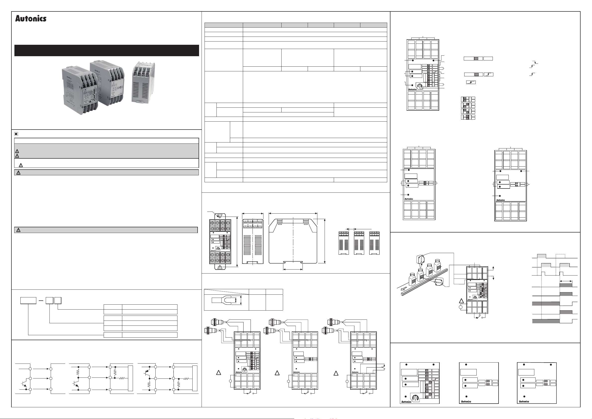
▣ Ordering Information
PA10
I
tem
▣ Input Connections
●
PA10-U
NPN open
collector
output
type sensor
※
The above specications are subject to change and some models may be discontinued without notice.
※
Be sure to follow cautions written in the instruction manual and the technical descriptions
(catalog, homepage).
I-
+12V
IN1, N2
0V
U
Function
Sensor
controller
(
(
Input
9
⑨, ⑬
⑪ IN1
⑮ IN2
⑩
⑭
●
PA10-V/PA10-W
NPN open
collector type &
NPN universal
output type sensor
No mark NPN input
P PNP input
U High function controller
V Controller
W 2 Channel controller
PA10 Multi-function power amplier
Sensor
+12V
IN1, IN2
controller
0V
●
1.8㏀
9.4㏀
Main circuit
2
) to AWG 15 (1.65mm2)
PA10-VP/PA10-WP
PNP open
collector type &
PNP universal
output type sensor
+12V
N1, IN2
0V
I I I
Sensor
controller
5 6㏀
5.4㏀
▣ Specications
Model PA10-U PA10-V PA10-VP PA10-W PA10-WP
Power supply 100-240VACᜠ 50/60Hz
Allowable voltage range
Power consumption
Power for external
sensor
Input(IN1, IN2)
Input method
Contact output OUT[250VACᜠ 3A(Resistive load)]
Out-
Solid-state
put
output
90 to 110% of rated voltage
Max. 10VA (condotion:12VDC/200mA resistive load)
12VDCᜡ ±10% approx. 200mA
Selectable NORM/INV.
Selectable OR/AND
operation for IN1, IN2
input. Selection function
for N2 derivative action.
NPN input type
●
PA10-U
[No-voltage input] Impedance at short-circuit: Max. 680Ω, Residual voltage at short circuit: Max. 0.8V, Impedance at open: Min. 100kΩ
●
PA10-V/PA10-W
[No-voltage input] Impedance at short-circuit: Max. 300Ω, Residual voltage at short circuit: Max. 2V, Impedance at open: Min. 100kΩ
●
PA10-VP/PA10-WP
[Voltage input]
Input impedance: 5.6kΩ, "H" level voltage: 5-30VDCᜡ, "L" level voltage: 0-2VDC
OᆞC OUT1, OᆞC OUT2
NPN open collector output Max. 30VDCᜡ Max. 100mA
Selectable NORM/INV.
Operation for IN1, IN2 AND.
NPN input type PNP input type NPN input type PNP input type
OᆞC OUT
I
Response time Relay output : Max. 10ms, Transistor output : Max. 0.05ms
●
Time setting
function by
each mode
※Only for
PA10-U
Relay
Mechanical Min.10,000,000 times
life
Electrical Min.100,000 times(250VAC 3A resis ive load)
cycle
ON-DELAY MODE
●
ONE-SHOT DELAY MODE
Have
●
FLICKER ONE-SHOT MODE
●
HIGH-SPEED DETECTION MODE
●
Non
NORMAL MODE
●
FLIP-FLOP MODE
Dielectric strength 2000VAC 50/60Hz for 1 minute
Insulation resistance Over 100MΩ(at 500VDC megger)
Ambient
Envi-
ron
ment
temperature
Ambient
humidity
-10 to 55℃ [Storage: -25 to 60℃]
35 to 85%RH [Storage: 35 to 85%RH]
Unit weight Approx. 150g Approx. 160g
※If the load is connected over 200mA at the sensor output, it may cause mechanical trouble.
※Environment resistance is rated at no freezing or condensation.
T
Selectable NORM/INV.
Selection func ion for
IN1, IN2 individual operation.
I
OUT1, OUT2 [250VACᜠ 3A(Resistive load)]
I
I
-
I
●
OFF-DELAY MODE
●
FLICKER MODE
●
LOW-SPEED DETECTION MODE
●
ON/OFF-DELAY MODE
●
ENCODER(MODE 9 to 11)
I
▣ Dimensions and Installation Interval
◎ Dimensions ◎ Installation interval
Ø5
OUT1
PA10-U
IN 1
IN 2
POWER
J
OR
NORM
NORM
NORM
M
O
O
F
D
F
E
O
TIME
F
F
MADE IN KOREA
OUT2
38
AND
INV
INV
SA
O
SB
SC
N
SD
94±0.5
T1
O
T2
N
I.
82
35 5
• I
(
Unit
: mm)
When installing multiple sensor
controllers, please keep space
between units at least 10mm for
heat radiation.
76
▣ Connections
※
Use teminals of size specied below.
a b
a
b
●
Main circuit
PA10-U
Brown
SOURCE
100-240VAC
50/60Hz
<Forked>
Brown
Black
Blue
!
~
Min.
3.5mm
Blue Blue
Black Black
+12V GND IN1
+12V
GND
IN2
15
14
13
OUT1
OR
PA10-U
NORM
NORM
IN 1
NORM
M
O
IN 2
O
F
D
F
E
POWER
A
O
T ME
D
F
F
MADE IN KOREA
7
6
5
NC
COM
3
2
1
CONTACT OUT:
250VAC 3A
RESISTIVE LOAD
OUT2
OᆞC
OUT1
OᆞC
OUT2
O
N
O
N
NO
1211109
16
AND
NV
INV
SA
SB
SC
SD
T1
T2
8
4
Max.
7.0mm
I I
●
PA10-V/PA10-VP
Blue
Brown
!
SOURCE
100-240VAC
50/60Hz
Brown
+12V GND IN1
+12V
GND
13
14
OUT
PA10-V
IN 1
IN 2
POWER
5
6
~
NC
1
2
CONTACT OUT:
250VAC 3A
RESISTIVE LOAD
OᆞC
IN2
15
NORM
NORM
MADE IN KOREA
7
COM
3
●
1211109
OUT
16
INV
INV
8
NO
4
PA10-W/PA10-WP
Brown
BlackBlack
Blue
Brown
!
SOURCE
100-240VAC
50/60Hz
~
+12V GND IN1
+12V
13
OUT1
PA10-W
POWER
5
1
CONTACT OUT1,OUT2:
250VAC 3A
RESISTIVE LOAD
I
I
Min. 10mm
Blue
IN2
GND
15
14
IN 1
NORM
NORM
IN 2
MADE IN KOREA
7
6
NC2
COM2
NC1
COM1
3
2
Black
OUT2
NO2
NO1
1211109
16
NV
NV
8
4
OUT2
OUT1
▣ Front Panel Indentication
●
PA10-U
!
9
+12V
+12V
13
2
OUT 1
PA10-U
4
1
POWER
_,
5
1
8888
●
PA10-V/PA10-VP
9
+12V
+12V
13
8888
2
OUT
-~-
PA10-V
c=J
IN 1
-
~
3
IN 2
~
POWER
1
-~-
Aulonko
5
1
8888
GND
GND
NC
IN 1
IN 2
..
10
14
6
2
GND
GND
A
D
J
11
10
IN 1
IN 2
14
15
OR
NORM
NORM
NORM
M
O
O
F
D
F
E
O
F
F
MADE IN KOREA
7
6
NC
COM
3
2
5
11
IN 1
IN 2
15
NORM
~=
NORM
MADE IN KOREA
7
COM
3
OUT 2
12
OᆞC
OUT
16
INV
INV
=
8
NO
4
12
OᆞC
OUT1
OᆞC
OUT2
3
16
5
AND
INV
6
INV
7
SA
O
SB
8
SC
N
SD
T1
O
9
N
T2
0
8
NO
4
1
Power indicator
LED turns on when
AC power applied.
2
Output indicator
Indication of output
signal.
Sensor input indicator
3
input signal.
J-
4
● PA10-VP: LED turns on
4
Selection switch of
sensor input signal
5
Terminal block
※When IN1, N2 input signal is AND, OUT will work.
Power indicator LED turns on when AC power applied
1
Output indicator 1 Indication of output 1 operation status
2
Output indicator 2 Indication of output 2 operation status
3
Sensor input indicator lndication of sensor input signal
4
AND/OR selection switch Select "AND" or "OR" for IN1, IN2 Input
5
Selection switch of sensor input signal
6
(Input signal reverse turn function)
NORM
I
●
NORM : When input signal is low, it is valid signal. ( )
●
INV : When input signal is high, it is valid signal. ( )
Derivative action selection of IN2 input signal (AND/OR selection switch: AND)
7
(When input signal is high( ), it is effective signal)
NORM
I
●
NORM : IN2 input signal is operating as reverse turn function
●
1__s-1
Selection switch for operation mode See "▣ Operation mode" in next page.
8
Selection switch of time range and max. input frequency It is the switch
9
to select time range(1 to 7 mode) or allowable input frequency(9 to 11 mode).
O
F
083]8
F
O
F
F
Da9B
O
F
F
□
~El
O
F
F
DESDB
Timer volume Adjust time within the range which is set with
0
Terminal block
!
(LED turns on when sensor input is Low)
INV
ID
11=::J
t..._
I
I
□
11
I I
:
Derivative action of IN2 input signal. ※See "▣ Derivation action applications"
T1
O
●
Time range: Approx. 0.01 to 0.1sec, Max. input frequency: 100kHz
N
T2
T1
O
●
Time range: Approx. 0.1 to 1sec, Max. input frequency: 10kHz
N
T2
T1
O
●
Time range: Approx. 0.1 to 10sec, Max. input frequency: 1kHz
N
T2
T1
O
●
Time range: Approx. 10 to 100sec, Max. input frequency: 100Hz
N
T2
●
PA10-W/PA10-WP
I
6
lndication of sensor
●
PA10-V: LED turns on
when sensor input is Low
when sensor input is High
●
NORM: When sensor
input signal is Low,
it is vaild signal.
●
INV: When sensor input
signal is High, it is vaild
signal.
9
+12V
+12V
13
8888
2
OUT1
PA10-W
c=J
~~}-
4
~
POWER
1
~-
Autonlu
5
1
8888
11
10
IN 1
GND
IN 2
GND
14
15
• •
IN 1
IN 2
NC2
NC1
6
2
OUT2
NORM
NORM
MADE IN KOREA
7
NO2
COM2
NO1
COM1
3
12
16
3
INV
5
INV
8
4
※IN1, IN2 operates individually.
1
2
3
4
5
6
▣ Derivative Action Applications
◎ Detect label of glass bottle
2
OᆞC
OUT1
OᆞC
OUT2
IN1
(Sensor for
detecting
the target)
IN2
(Sensor for
synchronization)
Derivative action
OUT (3-4)
OUT1
OᆞC OUT1
(10-12)
OUT2
OᆞC OUT2
(14-16)
ON
OFF
ON
OFF
ON
OFF
ON
OFF
ON
OFF
ON
OFF
ON
OFF
......---i-----,
ON
OFF
BEN300-DDT
N2
(Sensor for
synchroni-
zation)
IN1
(Sensor for detec ing
he target)
BEN300-DDT
SOURCE
100-240VAC
50/60Hz
Brown
Blue
Black
Brown
!
~
9
13
OUT1
PA10-U
POWER
5
1
Blue
10
14
IN 1
IN 2
J
6
2
Black
11
15
OR
NORM
NORM
NORM
M
O
O
F
D
F
E
O
IME
F
F
MADE IN KOREA
7
3
OUT2
12
16
AND
INV
INV
SA
O
SB
SC
N
SD
T1
O
N
8
4
Output((OUT)
●
Operation
When IN1 is ON and IN2 is ON, OUT will not work.
But when there is no label on bottle, OUT will work when IN2 is ON. OUT will be returned after setting time.
Note)Condition of detec ing label on glass bottle is to install with IN1 operating first.
▣ Factory Default for S/W
●
PA10-U
MODE1 ON-DELAY
• •
OUT1
PA10-U
POWER
IN 1
IN 2
A
D
J
OR
NORM
NORM
NORM
NORM
M
O
O
F
D
F
E
O
TIME
F
F
MADE IN KOREA
OUT2
AND
INV
INV
O
N
O
N
SA
SB
SC
SD
T1
T2
●
PA10-V NORM
●
PA10-VP NORM
•
OUT
PA10-
V
IN 1
~CJ
~CJ
IN 2
POWER
•
Autonics
INV
NORM
IBlD
NORM
INV
ru
□
MADE IN KOREA
●
PA10-W NORM
●
PA10-WP NORM
•
PA10-
W
IN 1
~CJ
~CJ
IN 2
POWER
•
Autonica
.
9
Power indicator
LED turns on when AC
power applied
Output 1 indicator
Indication of output 1
operation status.
Output 2 indicator
Indication of output 2
operation status.
Sensor input indicator
lndication of sensor
input signal.
●
PA10-W: LED turns on
when sensor input is Low.
●
PA10-WP: LED turns on
when sensor input is High.
Selection switch of
sensor input signal
●
NORM: When sensor
input signal is Low,
it is vaild signal.
●
INV: When sensor input
signal is High, it is vaild
signal.
Terminal block
Label No label
p
•
OUT2OUT1
INV
NORM
157
□
NORM
INV
ru
□
MADE IN KOREA
T
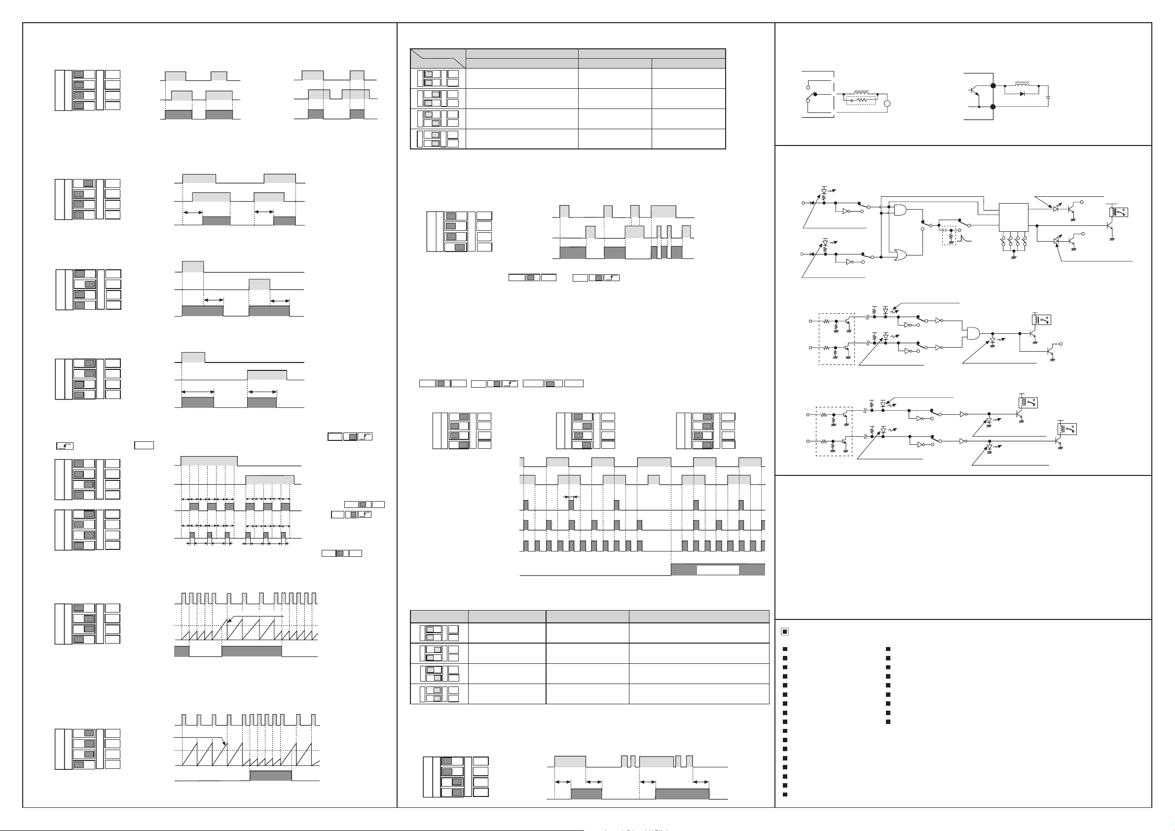
▣ Operation Mode
●
MODE 0 NORMAL MODE
: OUT will work according to input signal regardless Timer.
M
O
o::J
O
o::Ju
F
D
o::J
rn
F
E
o::J
●
MODE 1 ON-DELAY MODE
: OUT will be ON after setting time when one of IN1 and IN2 is ON. When IN1 and IN2 are OFF,
OUT will be OFF. (This is when input logic is OR)
M
O
O
F
~ua
D
o::J
F
rn
E
o::J
●
MODE 2 OFF-DELAY MODE
: OUT will be ON at he same time when IN1 or IN2 is ON then OUT will be OFF after setting time when
IN1 or IN2 is OFF. (This is when input logic is OR)
M
O
O
o::Ju
Cg]
F
D
o::J
rn
F
E
~□
●
MODE 3 ONE-SHOT DELAY MODE
: OUT will be ON at the same time when IN1 or IN2 is ON then OUT will be OFF after setting time.
(This is when input logic is OR)
M
c::g
c::gu
O
O
F
D
rn
o::J
F
E
~□
●MODE 4,5 FLICKER MODE / FLICKER ONE-SHOT MODE
: OUT will be ON after setting time for IN1 input then it is ickering and OUT will be ickering after setting
time from ON and IN2 input is same. Incase One-shot Mode, output time(Ts) will be selected by S/W.
( : Ts= Approx. 10ms, : Ts= Approx. 100ms)
M
O
O
o::J
o::Ju
c::g
F
D
rn
F
E
o::J
M
c::gu
O
O
o::J
c::g
F
D
rn
F
E
o::JD
●
MODE 6 LOW-SPEED DETECTION MODE
: OUT will be ON when input signal (IN1) is longer than setting time by comparing it to to the setting
time by one cycle.
M
c::g
O
O
o::Ju
c::g
F
D
rn
F
E
o::J
Note)Above is when input logic is OR and it will be the same by using IN2 input signal terminal instead
of IN1.
Note)When use MODE 6 as above, be sure that OUT will be work at he same time with power supply.
●
MODE 7 HIGH-SPEED DETECTION MODE
: OUT will be ON when input signal (IN1) is shorter than setting time by comparing it to to the setting
time by one cycle.
M
c::g
O
c::gu
O
c::g
F
D
rn
F
E
o::J
Note)Above is when input logic is OR and it will be the same by using IN2 input signal terminal instead
of IN1.
SA
SB
O
D
□
SC
D
N
SD
D
SA
SB
O
SC
D
N
SD
D
SA
O
SB
□
□
SC
D
N
SD
SA
D
□
O
SB
SC
D
N
SD
SA
O
SB
D
□
D
SC
N
SD
D
SA
□
O
SB
D
D
SC
N
SD
SA
D
O
SB
□
D
SC
N
SD
D
SA
D
□
O
SB
D
SC
N
SD
D
ON
IN1 IN1
OFF
ON
IN2 IN2
OFF
ON
OUT OUT
OFF
※Output will be ON when either
IN1
IN2
OUT
IN1
IN2
OUT
IN1
IN2
OUT
NORM
IN1
IN2
MODE 4
OUT
MODE 5
OUT
IN1
(IN2)
TIME
Setting
time
OUT
IN1
(IN2)
TIME
Setting
time
OUT
<OR function> <AND function>
-f7------17-
~
! ' j i
IN1 or IN2 is ON.
ON
_J
OFF
ON
OFF
ON
OFF
ON
OFF
ON
OFF
ON
OFF
ON
OFF
ON
OFF
ON
OFF
ON
OFF
ON
OFF
ON
OFF
ON
OFF
※T : Setting time, Ts : One-Shot output time
ON
OFF
ON
OFF
ON
OFF
ON
OFF
T
-17~----
_:_'--!
_]7
i i i i i
---4----'----'-----,-___,........,..___,........,,
: : : : : : : : l I I I
_
___,n,__.
T
~
___
T
T
T T T T T T T T T T
T T T T T T T T T T T
Ts Ts Ts Ts Ts Ts
Progressing time
~
Progressing time
~
ON
OFF
~
ON
~
OFF
ON
OFF
※Output will be ON when both
IN1 and IN2 are ON.
T
-
T
~
_
T
',,
,L
i ! ! 1 I
H H
T: Setting time
T: Setting time
T: Setting time
NORM
Note)ON/OFF rate of
Flicker output is 1:1.
Note) In case of Flicker Mode,
it is not different
between
NORM
and S/W.
Note) In case of One-Shot
Mode, it is not diffe-
rent between
OR
S/W se-
lections.
◎TIME S/W function(MODE 1 to MODE 7)
: Set the setting time by TIME S/W(T1, T2) and front TIME VOLUME(ADJ).
MODE 1 to MODE 7, MODE 12
I"---.
※Range of operating rpm is 1 pulse per 1 revolution.
※When the pulse is increasing per 1 revolution, range of opera ing rpm is decreasing.
●
◎ENCODER MODE(MODE 9 ~ MODE 11)
1) There should be 90°phase difference between IN1 and IN2 for input terminal.
2) Please connect A phase output of encoder to IN1 and B phase output of encoder to IN2, when use
3) There are output function of pulse(O.C OUT1) which has been multiplied(×1, ×2, ×4 times) against
4) Be sure to Input speed(cps) of connected equipment because pulse width of O.C OUT1 is short.
5) Selection S/W can be set at any position.
●
AND
OR
AND
◎TIME S/W function in Encoder mode
: TIME S/W is to convert output pulse width(Tw).
●
after setting time. (This is when input logic is OR)
MODE
TIME S/W
O
F
ocoo
F
IC[]
O
F
F
□
~DB
O
F
F
□
~DB
O
F
□
mo
F
o:::J
MODE 8 Flip-Flop MODE [OUT LATCH operation]
: When IN1 signal is input then the Flip-Flop output will be ON(SET). When the IN2 signal is input,
Flip-Flop Signal will be OFF(RESET).
M
O
O
F
D
rn
F
E
Note)IN2 will be the first of input signal.
Note)It is not different between and S/W.
Note)There is no Timer function in Flip-Flop Mode, therefore use this unit with Time S/W(T1, T2) as OFF.
NPN open collector or Totempole output type of encoder with controller.
In this case, turnded to CW direction detection signal(O.C OUT2, OUT) output of controller will be OFF.
input signal and direction detection output(O.C OUT2, OUT) function which detects direction of
encoder rotation in Encoder mode.
CJIQJD
MODE 9 ENCODER
(Input pulse×1time)
M
O
D
E
MODE 9
Input pulse
MODE 10
Input pulse
MODE 11
Input pulse
Direction
detection output
TIME S/W Max. input frequency Output pulse wid h(Tw)
O
F
F
□
~DB
O
F
F
□
~DB
O
F
F
DEEDB
O
F
orno
F
CD
MODE 12 ON/OFF-DELAY MODE
: OUT will be ON after setting time when IN1 (or IN2) is ON. When IN1 (or IN2) is OFF, OUT will be OFF
※If IN1 (or IN2) ON/OFF time is shorter than setting ime, OUT does not turn.
M
O
O
F
D
[FLJB
F
E
Setting time range Input frequency rpm
T1
"'
O
0.01 to 0.1sec 100 to 10Hz 6,000 to 600rpm
□
N
T2
□
T1
O
0.1 to 1sec 10 to 1Hz 600 to 60rpm
N
T2
T1
O
1 to 10sec 1 to 0.1Hz 60 to 6rpm
N
T2
T1
O
10 to 100sec 0.1 to 0.01Hz 6 to 0.6rpm
N
□
T2
□
ON
IN1
SA
O
o::Ju
~□
D::J D
CQD
O
F
F
T1
O
N
T2
T1
O
N
T2
T1
O
N
T2
T1
O
N
□
T2
□
c::g
c::g
SB
□
SC
N
SD
ANDOR
NORM
DC:::Cill~I
SA
O
SB
SC
N
SD
OᆞC
OUT1
OᆞC
OUT1
OᆞC
OUT1
OᆞC
OUT2
(OUT)
SA
SB
SC
SD
ON
OFF
ON
OFF
ON
OFF
ON
OFF
ON
OFF
ON
OFF
IN1
(A phase)
IN2
(B phase
X 1
X 2
X 4
100kHz Approx. 0.5㎲ Min. 2000kHz(2,000kcps)
10kHz Approx. 5㎲ Min. 200kHz(200kcps)
1kHz Approx. 50㎲ Min. 20kHz(20kcps)
100Hz
O
D
N
D
OFF
ON
IN2
OFF
ON
OUT
OFF
CJIQJD
IN1
(IN2)
OUT
ANDOR
NORM
c=JU:Oc=J
●
MODE 10 ENCODER
(Input pulse×2times)
※Note)Tw(pulse width) can be changed according to max. input frequency.
Approx. 500㎲ Min. 2kHz(2kcps)
ON
J
OFF
ON
OFF
MODE 6 to MODE 7
NORM
□
INV
M
O
O
F
D
F
E
Tw
!+---+j
rnl~
SA
O
SB
SC
N
SD
I
~
I
●
MODE 11 ENCODER
(Input pulse×4times)
M
O
D
E
rn
Input speed of connected equipment(cps)
nru
llil
TTT
1.-,
O
F
F
T
~
O
N
CCWCW
T: Set ing time
SA
SB
SC
SD
▣ Output
It is able to reduce noise generating if install surge obsorber between inductive loads(Motor, Solenoid, etc) as Picture 1.
When use DC Relay for load, please install a diode at relay coils as Picture 2. (Be sure to power polarity)
PA10 Series
NO
f
~I
NC
COM
Cl
(Picture 1) Relay output
-
s
·-------------·
~
d
※Surge obsorber (Load: 22Ω,
condenser: 0.1㎌, voltage: 630V)
~
※
SOURCE
PA10 Series
12
※
10
※Max. resisting pressure must be more than three
times of load voltage. Current capacity: 1A
(Picture 2) NPN open collector output
+
DC POWER
-
▣ Function Diagram
●
PA10-U
+5V
IN1
IN1 input indicator
IN2
IN2 input indicator
●
PA10-V/PA10-VP
IN1
7Tifll
' '
IN2
~
~--------·
※Add when it is PNP input
●
PA10-W/PA10-WP
IN1
IN2
※Add when it is PNP input
NORM
INV
NORM
INV
+12V
+12V
IN2 input indicator
----
+12V
+12V
IN2 input indicator
AND
(Derivative)
OR
IN1 input indicator
NORM
INV
NORM
INV
IN1 input indicator
NORM
INV
NORM
INV
NORM
Control
box
MODE S/W
OUT output indicator
OUT1 output indicator
OUT2 output indicator
OUT1 output indicator
~r
OUT2 output indicator
OᆞC
OUT1
OᆞC
OUT2
+12V
Lfr'-----
+12V
OUT
OᆞC
OUT
+12V
OUT1
+12V
OUT2
▣ Cautions during Use
1. Follow instructions in 'Cautions during Use'. Otherwise, it may cause unexpected accidents.
2. Use the product, 0.1 sec after supplying power.
3. When supplying or turning off the power, use a switch or etc. to avoid chattering.
4. Install a power switch or circuit breaker in the easily accessible place for supplying or disconnecting the power.
5. Keep away from high voltage lines or power lines to prevent inductive noise.
In case installing power line and input signal line closely, use line lter or varistor at power line and shielded wire at
input signal line.
Do not use near the equipment which generates strong magnetic force or high frequency noise.
6. This unit may be used in the following environments.
Indoors (in the environment condition rated in 'Specica ions')
①
Altitude max. 2,000m
②
Pollution degree 2
③
Installation category II
④
Major Products
Photoelectric Sensors Temperature Controllers
Fiber Optic Sensors Temperature/Humidity Transducers
Door Sensors SSRs/Power Controllers
Door Side Sensors Counters
Area Sensors Timers
Proximity Sensors Panel Meters
Pressure Sensors Tachometer/Pulse (Rate) Meters
Rotary Encoders Display Units
Connector/Sockets Sensor Controllers
Switching Mode Power Supplies
Control Switches/Lamps/Buzzers
I/O Terminal Blocks & Cables
Stepper Motors/Drivers/Motion Controllers
Graphic/Logic Panels
Field Network Devices
Laser Marking System (Fiber, Co₂, Nd: YAG)
Laser Welding/Cutting System
■
■
■
■
■
■
■
■
■
DRW171160AA
OUT
 Loading...