

Page 1
MT4Y/MT4W Series
Multi Panel Meter
DIN W72×H36mm, W96×H48mm, Digital Multi Panel Meter
Features
● Super version of panel meter
● Various output options (Default: Indicator)
RS485 Communication output, Low speed serial output,
Current (4-20mA), BCD output, NPN/PNP open collector
output, Relay output
● Max. measuring input specication
: 500VDC, 500VAC, 5ADC, 5ACA
● Max. display range: -1999 to 9999
● High/Low scale function
● AC frequency measurement function: 0.1 to 9999Hz
● Various functions: Monitoring function for max. and
min. display value function, display cycle delay function,
Zero function, High display correction function,
Current output scale function
● Wide range of power supply: 12-24VDC, 100-240VAC 50/60Hz
Please read “Caution for your safety” in operation
manual before using.
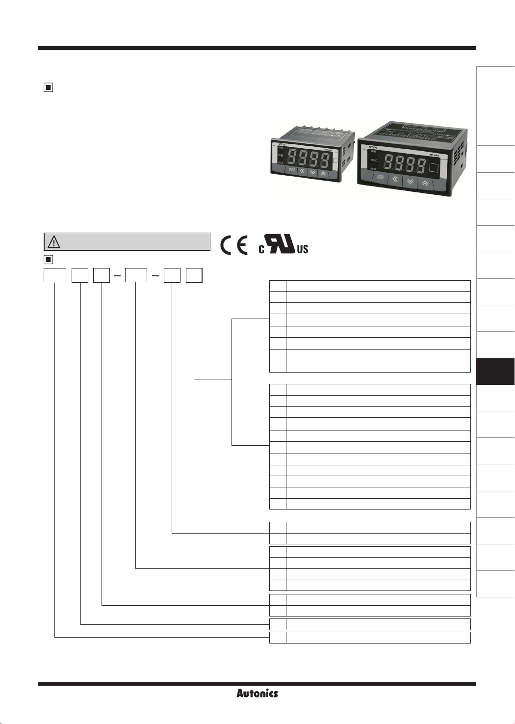
Ordering Information
MT DV4 4 NW
Y Type
Output
W Type
Power supply
Input
Size
Digit
Item
※
MT4Y-☐-43 (Relay output (Low out)+Transmission output (DC4-20mA) models.
※
※
※
lST
1: Only
2:
To measure the current over DC 5A, please select DV type because the shunt should be used.
In case of selecting frequency display, no output will be provided even if it is output support models. (Main output, Sub output and RS485 output)
(preset output mode) setting is available in MT4Y-☐-43 (Relay output (Low out)+Transmission output (DC4-20mA)) and
Only for MT4W.
N Indicator (Without output function)
0 Relay output
1 NPN open collector output
2 PNP open collector output
※
1
Relay output (Low out)+Transmission output (DC4-20mA)
3
※
1
4
Relay output (Low out)+RS485 communication output
5 BCD dynamic output
6 Low speed serial output
※
Output (0 to 6): Option
N Indication type (No output function)
0 Relay output+Transmission output (DC4-20mA)
1 Relay output
2 NPN open collector output+BCD dynamic output
3 PNP open collector output+BCD dynamic output
4 NPN open collector output+Transmission output (DC4-20mA)
5 PNP open collector output+Transmission output (DC4-20mA)
6 NPN open collector output+Low speed serial output
7 PNP open collector output+Low speed serial output
8 NPN open collector output+RS485 output
9 PNP open collector output+RS485 output
※
Output (0 to 9): Option
※
2
1
12-24VDC
4 100-240VAC 50/60Hz
DV DC voltage
DA DC current
AV AC voltage
AA AC current
Y DIN W72×H36mm
W DIN W96×H48mm
4 9999 (4digit)
MT Multi meter
L-35
(A)
Photoelectric
Sensors
(B)
Fiber
Optic
Sensors
(C)
Door/Area
Sensors
(D)
Proximity
Sensors
(E)
Pressure
Sensors
(F)
Rotary
Encoders
(G)
Connectors/
Sockets
(H)
Temperature
Controllers
(I)
SSRs / Power
Controllers
(J)
Counters
(K)
Timers
(L)
Panel
Meters
(M)
Tacho /
Speed / Pulse
Meters
(N)
Display
Units
(O)
Sensor
Controllers
(P)
Switching
Mode Power
Supplies
(Q)
Stepper Motors
& Drivers
& Controllers
(R)
Graphic/
Logic
Panels
(S)
Field
Network
Devices
(T)
Software
Page 2
MT4Y/MT4W Series
Specifications
Series
Measurement input
Power supply
Power consumption 5VA 5W
Display method 7Segment LED display (red) (Character height: 14.2mm)
Display accuracy
Max. allowable input 110% F.S for each measured input range
A/D conversion method Practical oversampling using successive approximation ADC
Sampling cycle DC type: 50ms, AC type: 16.6ms
Max. indication range -1999 to 9999 (4digit)
Preset output
Sub output
(Transmission output)
AC measuring function
Frequency measurement function
Hold function
Insulation resistance Min. 100MΩ (at 500VDC megger) between external terminal and case
Dielectric stength 2,000VAC for 1minute between external terminal and case
Noise stength ±2kV the square wave noise (pulse width: 1㎲) by the noise simulator
Vibration
Shock
Relay
life cycle
Environ
-ment
Insulation type
Approval
Unit weight Approx. 134g Approx. 211g
※
1: AC measuring function, and frequency measuring function are only for AC measuring input type.
※
2: MT4Y-
※
Environment resistance is rated at no freezing or condensation.
※
Mechanical 0.75mm amplitude at frequency of 10 to 55Hz (for 1 min.) in each X, Y
Malfunction 0.5mm amplitude at frequency of 10 to 55Hz (for 1 min.) in each X, Y
Mechanical 100m/s² (approx. 10G) in each X, Y, Z direction for 3 times
Malfunction 300m/s² (approx. 30G) in each X, Y, Z direction for 3 times
Malfunction Min. 20,000,000 operations
Mechanical Min. 100,000 operations (250VAC 3A Load current)
Ambient temperature -10 to 50℃, storage: -20 to 60
Ambient humidity 35 to 85%RH, storage: 35 to 85%RH
If only frequency input the AC type (display method of measuring input) which option is in MT4W, MT4W will operate the only indicator
type.
-4N model has no hold function.
※
2
MT4Y-DV-4
MT4Y-DA-4
DC voltage,
current
100-240VAC 50/60Hz
(Allowable voltage range: 90 to 110%)
• 23℃±5
• -10℃ to 50
• Relay output - Contact capacity: 250VAC 3A, 30VDC 3A / Contact composition: N.O (1a)
• NPN/PNP Open collector output - 12-24VDC ±2V 50mA Max. (Resistive load)
• RS485 communication output Synchronous method: Asynchronous method, Protocol: Modbus type
• Serial/BCD output - NPN Open collector output: 12-24VDC Max. 50mA (Resistive load)
• DC4-20mA output - Resolution: 12,000 division (Load resistance max. 600Ω)
1
Selectable RMS or AVG
※
1
Measurement range: 0.100 to 9999Hz (Variable by decimal point position)
Includes (External hold function)
Double insulation or reinforced insulation
(Mark:
MT4Y-AV-4
MT4Y-AA-4
AC voltage,
current,
Frequency
DC Type: F.S. ±0.1% rdg±2digit / AC Type: F.S. ±0.3% rdg±3digit
℃ -
DC/AC Type F.S +0.3% rdg +3digit max. only for 5A terminal.
DC/AC Type: F.S.±0.5% rdg±3digit
℃ -
, dielectric strength between the measuring input part and the power part: 1kV)
MT4W-DV-4
MT4W-DA-4
DC voltage,
current
Baud rate: 1200/2400/4800/9600, Communication method: 2-wire half duplex,
℃
MT4W-AV-4
MT4W-AA-4
AC voltage,
current,
Frequency
MT4W-DV-1
MT4W-DA-1
DC voltage,
current
12-24VDC
(Allowable voltage range: 90 to 110%)
, Z direction for 2 hours
, Z direction for 10 min.
MT4W-AV-1
MT4W-AA-1
AC voltage,
current,
Frequency
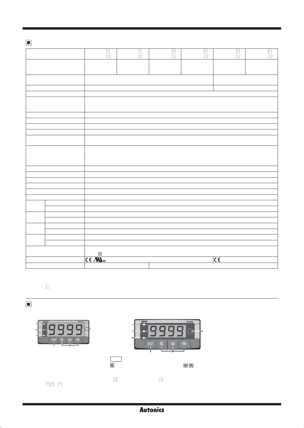
Unit Description
● MT4Y Series ● MT4W Series
1
2
3
5
4
1. HI: High output indication of preset
2. GO: GO output indication of preset
3. LO: Low output indication of preset
※
There is no 1, 2, 3 on a display panel of MT4Y-
※
In MT4Y- - 3, 4, OUT is used for Go output display and there is no 1, 3 in display panel.
6
4.
5.
6. Unit label part
L-36
1
2
3
MODE
key: Mode Key
: Moves digit, enters parameter mode, : changes SV
-4N, 45, 46 and MT4W- -4N.
4
5
6
Page 3
Multi Panel Meter
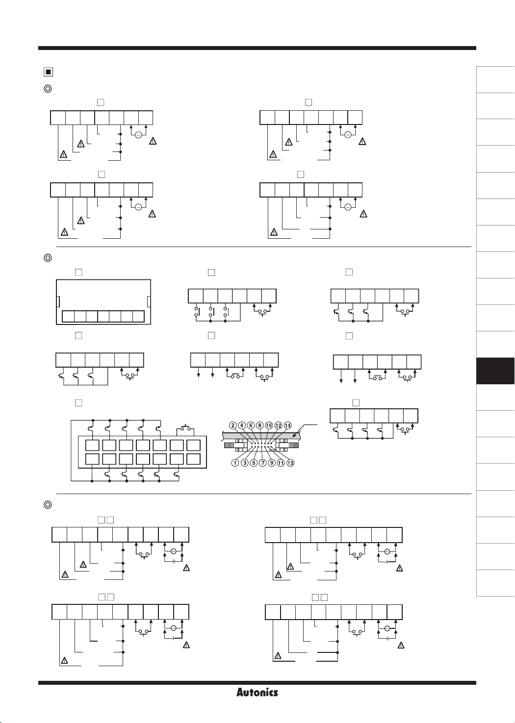
Connections
Measuring input connection of MT4Y Series
● MT4Y-DV-4
1 2 3 4 5 6 7
250mV
/50mV
5mA
/2mA
250mV
/50mV
5V/1V
5mA
/2mA
50mA/
4-20mA
SOURCE
100-240VAC
50/60Hz 5VA
SOURCE
100-240VAC
50/60Hz 5VA
Hold/Zero
Hold/Zero
Hold/Zero
●MT4Y- -40
(Triple relay output)
8 9 10 11 12 13
HI GO LO COM
●MT4Y- -43
(Relay output+Transmission output)
+ -
Hold/Zero
+ -
SOURCE
12-24VDC
100-240VAC
50/60Hz 5VA
+ -
SOURCE
12-24VDC
100-240VAC
50/60Hz 5VA
DC4-20mALoad
600Ω max.
OUT
※
Hirose connector pin header model of the unit: HIF3BA-14PA-2.54DS
※
Contact Hirose Electric to purchase socket and wires of Hirose connector.
[Socket: HIF3BA-14D-2.54R]
5V/1V
50V/10V
500V/100V
● MT4Y-DA-4
1 2 3 4 5 6 7
50mA/
4-20mA
500mA/200mA
5A/2A
Output terminal of connection of MT4Y Series
●MT4Y- -4N (Indicator)
1 2 3 4 5 6 7
●MT4Y-
-42
(Triple PNP O.C output)
8
9 10 11 12 13 8 9 10 11 12 13
HI GO LO COM
●MT4Y- -45
(BCD Dynamic output)
A C D0 D2 Dot
2 4 6 8 10 12 14
1 3 5 7 9 11 13
COM POLB D D1 D3
Measuring input connection of MT4W Series
● MT4W-DV-
1 2 3 4 5 6 7 8 9
50V/10V
500V/100V
● MT4W-DA-
1 2 3 4 5 6 7 8 9
500mA/200mA
5A/2A
● MT4Y-AV-4
1 2 3 4 5 6 7
2V/1V
20V/10V
110V/50V
500V/250V
SOURCE
100-240VAC
50/60Hz 5VA
● MT4Y-AA-4
1 2 3 4 5 6 7
100mA
/50mA
500mA
/250mA
1A
5A/2.5A
SOURCE
100-240VAC
50/60Hz 5VA
●MT4Y- -41
(Triple NPN O.C output)
8 9 10 11 12 13
Hold/Zero
HI GO LO COM
Hold/Zero
●MT4Y- -44
(Relay+RS485 communication output)
8 9 10
B (-) A (+)
Hold/Zero Hold/Zero
RS485
●MT4Y- -46
PCB
8 9 10 11 12 13
CLOCK DATA LATCH POL COM
※
POL: When a display value is "-", the signal
of "-" will be outputted.
11 12 13
OUT
(Low speed serial output)
Hold/Zero
● MT4W-AV-
1 2 3 4 5 6 7 8 9
110V/50V
500V/250V
2V/1V
20V/10V
Hold/Zero
+ -
SOURCE
12-24VDC
100-240VAC
50/60Hz 5VA
● MT4W-AA-
1 2 3 4 5 6 7 8 9
100mA
5A/2.5A
500mA
/250mA
1A
/50mA
Hold/Zero
+ -
SOURCE
12-24VDC
100-240VAC
50/60Hz 5VA
(A)
Photoelectric
Sensors
(B)
Fiber
Optic
Sensors
(C)
Door/Area
Sensors
(D)
Proximity
Sensors
(E)
Pressure
Sensors
(F)
Rotary
Encoders
(G)
Connectors/
Sockets
(H)
Temperature
Controllers
(I)
SSRs / Power
Controllers
(J)
Counters
(K)
Timers
(L)
Panel
Meters
(M)
Tacho /
Speed / Pulse
Meters
(N)
Display
Units
(O)
Sensor
Controllers
(P)
Switching
Mode Power
Supplies
(Q)
Stepper Motors
& Drivers
& Controllers
(R)
Graphic/
Logic
Panels
(S)
Field
Network
Devices
(T)
Software
L-37
Page 4
MT4Y/MT4W Series
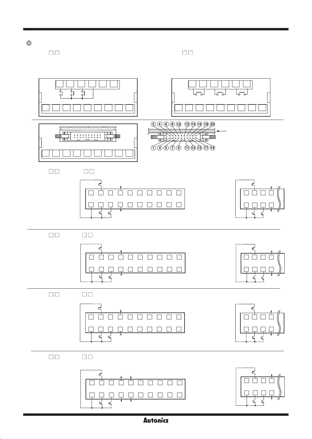
Output terminal connection of MT4W Series
● MT4W- - 0
+Transmission output)
(Triple relay output
MAIN OUT
CONTACT OUT
: 250VAC 3A 1a RESISTIVE LOAD
10 11 12 13 14 15 10 11 12 13 14 15
+
-
DC4-20mA
HIHIGOGOLOLOCOM
Load 600Ω Max.
● MT4W- - 1 (
MAIN OUT
CONTACT OUT
: 250VAC 3A 1a RESISTIVE LOAD
1 2 3 4 5 6 7 81 2 3 4 5 6 7 8 9
Triple relay output)
9
PCB
1 2 3 4 5 6 7 8 9
● MT4W- - 2 / MT4W- - 3
GO
MAIN OUT:
NPN OPEN COLLECTOR
12-24VDC Max. 50mA
2 4 6 8 10 12 14 16 18 20
1 3 5 7 9 11 13 15 17 19
COM1 HI LO
● MT4W- - 4/ MT4W- - 5 (
GO
MAIN OUT:
NPN OPEN COLLECTOR
12-24VDC Max. 50mA
2 4 6 8
COM1
● MT4W- - 6/ MT4W- - 7
GO
MAIN OUT:
NPN OPEN COLLECTOR
12-24VDC Max. 50mA
2 4 6 8 10 12 14 16 18 20
1 3 5 7 9 11 13 15 17 19
COM1 HI LO
● MT4W- - 8/ MT4W- - 9
GO
MAIN OUT:
NPN OPEN COLLECTOR
12-24VDC Max. 50mA
2 4 6 8 10 12 14 16 18 20
1 3 5 7 9 11 13 15 17 19
COM1 HI LO
※
Hirose connector pin header model of the unit: HIF3BA-20PA-2.54DS
※
Contact Hirose Electric to purchase socket and wires of Hirose connector.
[Socket: HIF3BA-20D-2.54R]
(Triple NPN/PNP open collector output+BCD output)
+24VDC
30mA Max.
0V
A C D0 D2
BCD OUT:
NPN OPEN COLLECTOR
12-24VDC Max. 50mA
COM2DOT
D3D1DB
MAIN OUT:
PNP OPEN COLLECTOR
12-24VDC Max. 50mA
POL
※
POL: When a display value is "-", the signal of "-" will be
outputted.
Triple NPN/PNP open collector output+Transmission output)
+24VDC
HI LO
30mA Max.
10 12 14 16 18 20
9 11 13 15 17 191 3 5 7
0V
(-)
(+)
Current:
DC4-20mA LOAD 600Ω Max.
MAIN OUT:
PNP OPEN COLLECTOR
12-24VDC Max. 50mA
(Triple NPN/PNP open collector output+Low speed serial output)
※
+24VDC
30mA Max.
0V
POL: When a display value is "-", the signal of "-" will be
outputted.
MAIN OUT:
PNP OPEN COLLECTOR
12-24VDC Max. 50mA
COM2 DATA
SERIAL OUT:
NPN OPEN COLLECTOR
12-24VDC Max. 50mA
(Triple NPN/PNP open collector output+RS485 output)
+24VDC
RS485
30mA
B (-)
Max.
0V
A (+)
RS485
MAIN OUT:
PNP OPEN COLLECTOR
12-24VDC Max. 50mA
GO
2 4 6 8
1 3 5 7
COM1 HI LO
GO
2 4 6 8
1 3 5 7
COM1 HI LO
GO
2 4 6 8
1 3 5 7
COM1 HI LO
GO
2 4 6 8
1 3 5 7
COM1 HI LO
+24VDC
30mA Max.
0V
+24VDC
30mA Max.
0V
+24VDC
30mA Max.
0V
+24VDC
30mA Max.
0V
L-38
Page 5
Multi Panel Meter
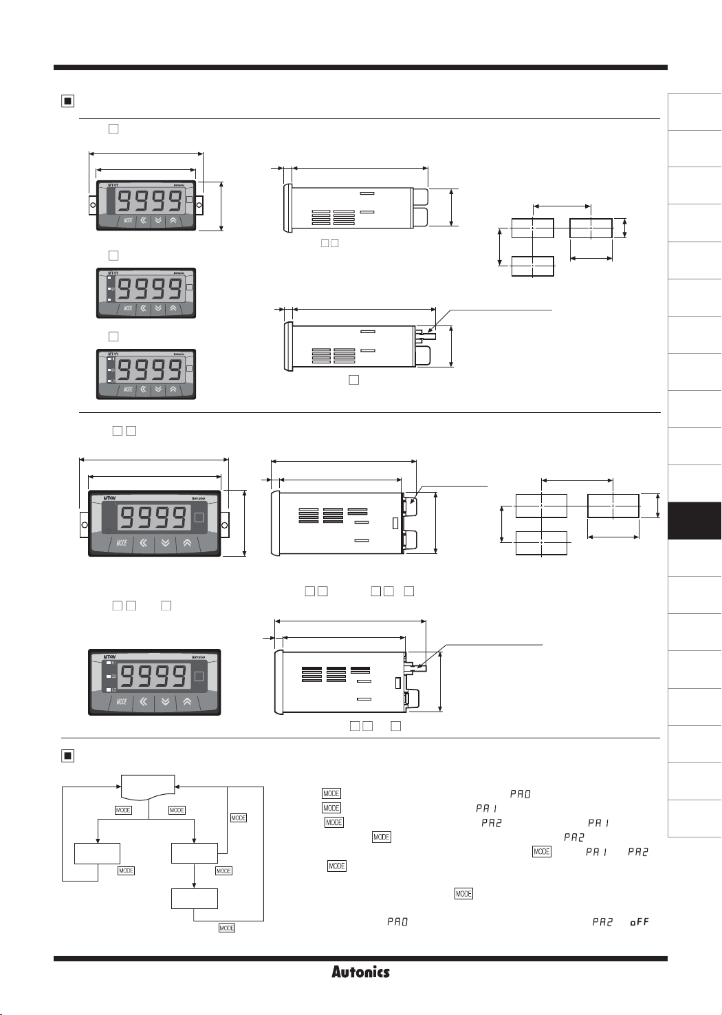
Dimensions
● MT4Y- -4N, 45, 46
85
72
● MT4Y- -43, 44
● MT4Y-
-40, 41, 42
● MT4W- - N (Indicator)
109
96
● MT4W-
- 0 to 9
Parameter Setting
RUN
Press Key
PA0
Press Key
Press Key
PA1
PA2
Press
for 2sec.
Press
for 3sec.
36
6 77
<MT4Y- -4N, 40 to 44, 46>
6
<MT4Y-
106
89.56
48
※
There is no Relay output terminal block in
indication type.
< MT4W- - N, MT4W- - 0, 1 >
110.4
6
89.5
< MT4W- - 2 to 9 >
Press
for 3sec.
Key
※
※
※
Press
Press
Press
key in RUN status, it will advance to [ ] (Parameter 0) group.
key for 2 sec. in RUN mode, [ ] is displayed.
When pressing key continually, it stops displaying at [ ].
※
It is advanced to current display parameter releasing
※
Key
Press
※
If any key is not touched for 60 sec. in each parameter, it returns to RUN mode.
※
After return to RUN mode, press
parameter. (Refer to the below descriptions for set parameter.)
※
Key
It cannot advance to[
● Panel cut-out
Min. 91
+ 0.7
0
68
77
-45>
30
Min. 40
10 Pin Hirose connector
(HIF3BD-10PA-2.54DS)
30
● Panel cut-out
Relay contact
output terminal
44.8
Min. 52
20 P in H iros e co nnec tor
(HIF3BA-20PA-2.54DS)
44.8
key for 4 sec. in RUN mode, [ ] is displayed after [ ].
key for 3 sec., it is returned to RUN at any position.
key within 2 sec., it returns to previous
] when preset output operation mode of [ ] is [ ] .
Min. 116
key at [ ] or [ ].
(unit: mm)
31.5
+ 0.8
92
0
+ 0.5
0
+ 0.6
0
45
(A)
Photoelectric
Sensors
(B)
Fiber
Optic
Sensors
(C)
Door/Area
Sensors
(D)
Proximity
Sensors
(E)
Pressure
Sensors
(F)
Rotary
Encoders
(G)
Connectors/
Sockets
(H)
Temperature
Controllers
(I)
SSRs / Power
Controllers
(J)
Counters
(K)
Timers
(L)
Panel
Meters
(M)
Tacho /
Speed / Pulse
Meters
(N)
Display
Units
(O)
Sensor
Controllers
(P)
Switching
Mode Power
Supplies
(Q)
Stepper Motors
& Drivers
& Controllers
(R)
Graphic/
Logic
Panels
(S)
Field
Network
Devices
(T)
Software
L-39
Page 6
MT4Y/MT4W Series
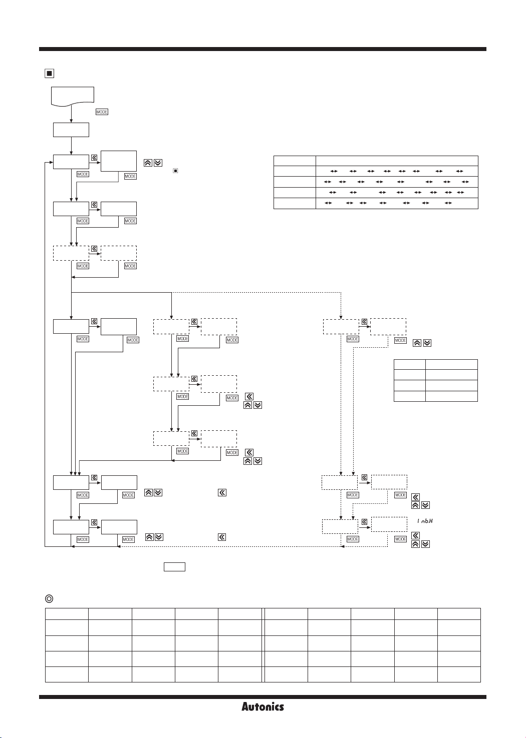
Parameter 1 Group
RUN
Press key for 3sec.
PA1
Display of factory
IN-R
DISP
IN-T
Wh en
STND
It shows Max. display
value of standard
specification.
Display value is fixed.
INbH
measuring input
STND
DISP
Max. display
!000
default for
AVG
is
value
INbL 00
※
After setting each mode, press
※
If any key is untouched for 60sec. after advance to Parameter, it will return to RUN.
Select measuring input specification by
.
Specification of
Refer to "
-
measuring input and range".
Select the display method of measuring input.
Set range:
STND, SCAL, FREQ
Refer to measuring input specification and range chart.
-
(
mode is only for AC measuring type.)
FREQ
Select measuring method for AC.
Set range:
(This parameter will be displayed only for AC measuring models. In
case of selecting frequency display, it will not be displayed.)
STND
DOT
H-SC
L-SC
It corrects a gradient of High-limit display value against max. input.
The setting range is 0.100 to 5.000 (%).
(
: Change setting value, : Shift the digit)
It corrects deviation of Low-limit display value against Min. input.
Setting range is -99 to 99. (Refer to zero point function)
(
: Set a deviation value, : Shift the digit)
MODE
(Average: AVG/Root mean square: RMS)
AVG, RMS
Wh en
is
DISP
Decimal point
Max. display
Min. display
SCAL
position
value
value
Select decimal point position.
Set range: 0,
※
point position, "
decimal point position.
Set display value against
max. measuring input.
(
: Change setting value)
Set display value against
min. measuring input.
( : Shift the digit
: Change setting value)
key for 2 sec. to return to RUN.
● Measuring input chart by model
Item Range of measuring input
MT4Y/W-DV
MT4Y/W-DA
MT4Y/W-AV
MT4Y/W-AA
※
(☆) Standard specification. (110P is 440VAC/110VAC P.T)
)0, )00, )000
When sele cti ng the decimal
H-SC
: Shift the digit
500V 100V 50V 10V 5V
5A 2A
500V
5
",
" have
L-SC
A
1V
)5A
)2A
110P
A
(☆)
)5
A
is
DISP
Decimal point
position
50MA
50V
)25
FREQ
A
250V
2.5
A
1
Wh en
(It is only displayed for AC measuring type.)
DOT
0.000
※
In case of selecting frequency display, no
output will be provided even if it is output
support models (Main output, Sub output
and RS485 output).
INbH
INbE
!000
10-0
0.25V
50ㅡMV
4-20MA
5MA
2MA
20V
10V
2V 1V
)1
A
50
mA
5
Set frequency measuring
range, it is decided as
the decimal point position.
(
Change the
decimal point position)
0
0.0
0.00
It corrects a gradient of
display value against max.
input.
Setting range:0.001 to 9.999
: Shift the digit
(
: Change setting
value)
Set
Setting range: 10-2 to 101
: Shift the digit
(
: Change setting
value)
A
1 to 9999Hz
0.1 to 999.9Hz
0.10 to 99.99Hz
0.100 to 9.999Hz
500V
500V
5A
Factory defaults
Parameter MT4Y/W-DV MT4Y/W-DA MT4Y/W-AV MT4Y/W-AA Parameter MT4Y/W-DV MT4Y/W-DA MT4Y/W-AV MT4Y/W-AA
ㅡIN-R 500V SA 500V SA INbH !000 !000 !000 !000
DISP STND STND STND STND INbL 00 00 00 00
IN-T
- -
STND 50)0 %000 50)0 %000 INbE
L-40
AVG AVG DOT )0 )000 )0 )000
- -
10-0 10-0
Page 7
Multi Panel Meter
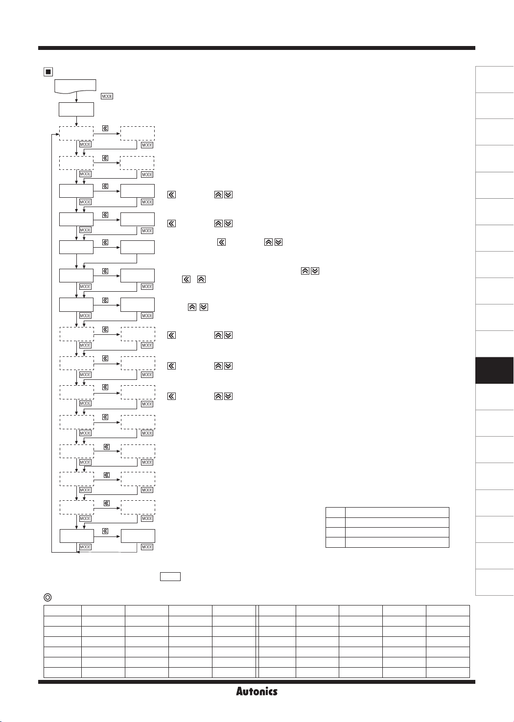
Parameter 2 Group
RUN
Press key for 5sec.
PA2
Move after 1sec.
OUtT
HYS
STaT
PEkT
D1sT
ZERO
EV1N HOLD
FS-H
FS-L
ADRS
BPS
OFF
HYS
0)0
00 5
)2 5
NO
50)0
00)0
01
9600
Select preset output mode. (only for available models)
Set range:
OFF, lST, hST, LhST, HhST, LlST, LdST
※
Only
setting is available in MT4Y-☐-43 and MT4Y-☐-44 models.
lST
Set preset hysteresis. Within 10% of F.S.
But, it is not displayed when
Set startup compensation time.
( :Shift the digit, : Change setting value)
Setting range: 0.0 to 99.9sec.
Set monitoring delay time.
(
:Shift the digit, : Change setting value)
Setting range: 00 to 30sec.
Set a display cycle. (
Setting range: 0.1 to 5.0sec.
Select zero function with operation at front. (Set with
When + Key key are pressed for 3 sec. to set
value is saved automatically at
Select input with 6, 7 (MT4W)[12, 13 (MT4Y)] terminal or zero function for external signal.
(Set with
: Holding display value,
HOLD
Set the high limit value, output point of current output 20mA.
:Shift the digit, : Change setting value)
(
(When changing measuring input and prescale mode, it is changed automatically
as maximum value of input range.)
Set the low limit value, output point of current output 4mA.
:Shift the digit, : Change setting value)
(
(When changing measuring input and prescale mode, it is changed automatically
as minimum value of input range.)
Set the address of RS485 communication output.
(
:Shift the digit, : Change setting value)
Setting range: 01 to
Select Baud rate of RS485 communication output.
Set range:
9600, 4800, 2400, 1200
:Shift the digit, : Change setting value)
, Key)
99
mode is
OVtT
ㅡ INbL
: Zero function using Hold/Zero terminal
ZERO
mode.
OFF
.
key)
, it will be zero function and the deviation
ㅡㅡㅡYES
(A)
Photoelectric
Sensors
(B)
Fiber
Optic
Sensors
(C)
Door/Area
Sensors
(D)
Proximity
Sensors
(E)
Pressure
Sensors
(F)
Rotary
Encoders
(G)
Connectors/
Sockets
(H)
Temperature
Controllers
(I)
SSRs / Power
Controllers
(J)
Counters
(K)
Timers
(L)
Panel
Meters
(M)
Tacho /
Speed / Pulse
Meters
(N)
Display
Units
PRTY
※1
NONE
※1
STP
RSmT 5
※1
LOC OFF
Set parity bit of RS485 communication.
Set range:
NONE, EVEN, ODD
Set stop bit of RS485 communication.
Set range: 1,
2
Set response wait time of RS485 communication.
Set range: 5 to 99
Set key lock function and select from 4 types.
Set range:
2
OFF, LOC1, LOC2, LOC3
Disable to lock keys
OFF
Lock Parameter 1
LOC1
Lock Parameter 1, 2
LOC2
Lock Parameter 0, 1 and 2
LOC3
※1: These parameters do not displayed in MT4W series.
※
The dotted mode is only displayed for output type.
※
After setting each mode, press
※
If any key is untouched for 60sec. after advance to PARAMETER, it will return to RUN mode.
MODE
key for 2 sec. to return to RUN mode.
Factory defaults
Parameter MT4Y/W-DV MT4Y/W-DA MT4Y/W-AV MT4Y/W-AA Parameter MT4Y/W-DV MT4Y/W-DA MT4Y/W-AV MT4Y/W-AA
OUtT OFF OFF OFF OFF EV1N HOLD HOLD HOLD HOLD
HYS 001 001 001 001 FS-H 50)0 %000 50)0 %000
STAT 0)0 0)0 0)0 0)0 FS-L 00)0 )000 00)0 )000
PEkT 00 5 00 5 00 5 00 5 ARDS 01 01 01 01
DIsT )2 5 )2 5 )2 5 )2 5 BPS 9600 9600 9600 9600
ZERO NO NO NO NO LOC OFF OFF OFF OFF
L-41
(O)
Sensor
Controllers
(P)
Switching
Mode Power
Supplies
(Q)
Stepper Motors
& Drivers
& Controllers
(R)
Graphic/
Logic
Panels
(S)
Field
Network
Devices
(T)
Software
Page 8
MT4Y/MT4W Series
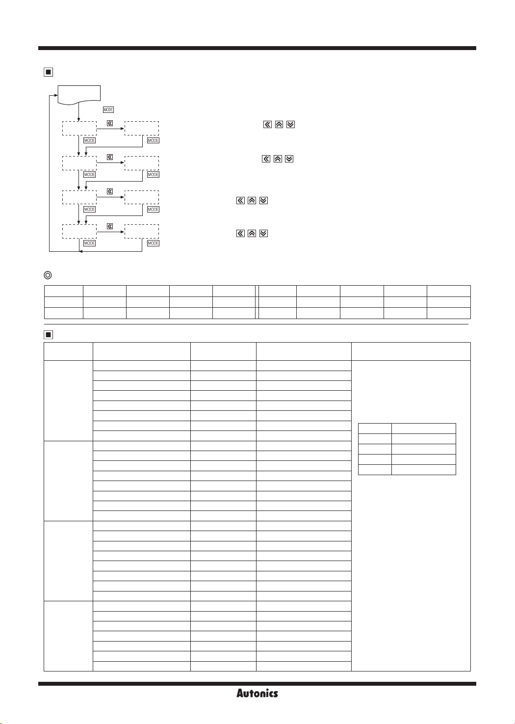
Parameter 0 Group
RUN
Press key
hSET
50)0
Set preset High-limit value. (Set with , , key)
※
It is displayed when set the preset only.
When set
OFF
i n
m od e if parameter 2 group, th e pa ra me ter is no t disp lay ed .
OUtT
lSET
00)0
hPEK
lPEK )0
※
If any key is untouched for 60sec. after advance to Parameter, it will return to RUN mode.
Set preset Low-limit value. (Set with
※
It is displayed when set the preset only.
When set
It shows High-limit monitoring value while it is in RUN mode.
)0
It will be reset by pressing
※
hPEK
It shows Low-limit monitoring value while it is in RUN mode.
It will be reset by pressing
※
lPEK
in
OFF
parameter is not displayed when
parameter is not displayed when
mode if parameter 2 group, the parameter is not displayed.
OUtT
, , key)
, , key.
, , key.
parameter is set as 00 sec.[
PEkT
parameter is set as 00 sec.[
PEkT
] at Parameter 2 group.
00 5
] at Parameter 2 group.
00 5
Factory defaults
Parameter MT4Y/W-DV MT4Y/W-DA MT4Y/W-AV MT4Y/W-AA Parameter MT4Y/W-DV MT4Y/W-DA MT4Y/W-AV MT4Y/W-AA
hSET 50)0 %000 50)0 %000 hPEK )0 )000 )0 )000
lSET 00)0 )000 00)0 )000 lPEK )0 )000 )0 )000
Measuring Input And Range
Type Measuring input and range Input impedance Display range [
500V
] 4.33MΩ 0.0 to 500.0
100V
] 4.33MΩ 0.0 to 100.0
50V
] 433.15kΩ 0.00 to 50.00
10V
] 433.15kΩ 0.00 to 10.00
0.25V
] 2.15kΩ 0.0 to 250.0
50MV
] 2.15kΩ 0.00 to 50.00
0.5A
] 0.1Ω 0.0 to 500.0
0.2A
] 0.1Ω 0.0 to 200.0
50MA
] 1.0Ω 0.00 to 50.00
4-20
] 1.0Ω 4.00 to 20.00
5MA
] 10.0Ω 0.000 to 5.000
2MA
]
500V
250V
110P
50V
] 1.08MΩ 0.00 to 50.00
20V
] 200kΩ 0.00 to 20.00
10V
] 200kΩ 0.00 to 10.00
2.5A
] 0.01Ω 0.000 to 2.500
0.5A
] 0.1Ω 0.0 to 500.0
0.25A
0.1A
] 0.5Ω 0.0 to 100.0
50MA
10.0Ω 0.000 to 2.000
] 4.98MΩ 0.0 to 500.0
] 4.98MΩ 0.0 to 250.0
] 1.08MΩ 0.0 to 440.0
] 0.1Ω 0.0 to 250.0
] 0.5Ω 0.00 to 50.00
DC voltage
DC current
AC voltage
AC current
0-500V [
0-100V [
0-50V [
0-10V [
0-5V [5V] 43.15kΩ 0.000 to 5.000
0-1V [1V] 43.15kΩ 0.000 to 1.000
0-250mV [
0-50mV [
0-5A [5A] 0.01Ω 0.000 to 5.000
0-2A [2A] 0.01Ω 0.000 to 2.000
0-500mA [
0-200mA [
0-50mA [
4-20mA [
0-5mA [
0-2mA [
0-500V [
0-250V [
0-110V [
0-50V [
0-20V [
0-10V [
0-2V [2V] 20kΩ 0.000 to 2.000
0-1V [1V] 20kΩ 0.000 to 1.000
0-5A [5A] 0.01Ω 0.000 to 5.000
0-2.5A [
0-1A [1A] 0.05Ω 0.000 to 1.000
0-500mA [
0-250mA [
0-100mA [
0-50mA [
] Prescale display range [
STND
DOT
0
)0
)00
)000
(The display range is changed
according to the decimal point
position.)
※
Please connect proper terminal its
max. input voltage is within 30 to
100% of input terminal.
When it is higher than input
voltage, it may cause a breakdown
of terminal and over display range
and the accuracy is decreased
when it is connected to the
terminal under 30%.
※
110P is standard specication
440V/110VAC P.T.
Display range
-1999 to 9999
-199.9 to 999.9
-19.99 to 99.99
-1.999 to 9.999
SCAL
]
L-42
Page 9
Functions
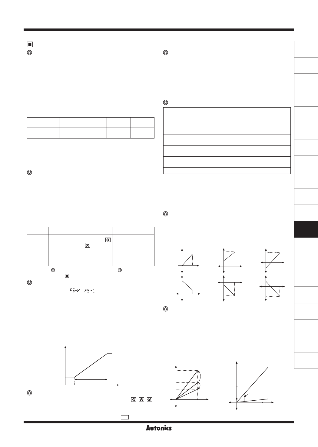
AC frequency measurement function
[PA 1 group:
It measures input signal frequency when it is AC input.
It uses fixed decimal point[PA1:
can be changed by setting and measured range of decimal
point position is as below chart. It is available to adjust the
upper gradient at [PA 1:
to measure frequency normally, input signal, over 10% F.S.
of the measured range, should be supplied. Please select
the proper point of
Measuring range
①
Decimal point
position
Measurement
range
※
Accuracy of frequency measurement:
Below 1kHz, F.S. ±0.1rdg ±2digit.
From 1kHz to 10kHz, F.S. ±0.3rdg ±2digit.
INbH
②
③
: 0.100 to 9.999 [Gradient adjustment of high value]
INbE:
10
Zero adjustment function
(Deviation correction function of low limit
display value)
It adjusts the display value of the optional configured input
value as zero by force, zero point error can be adjusted
with 3 ways as below. When zero point adjustment with
front key and Hold terminal is finished normally, zero point
of measurement terminal is displayed and the adjusted
value at saved in
Operation
Description
※
Input correction value
PA 1: Direct
input correction
value method at
INbL
Refer to "
function" and " Parameter 2" for function and error.
Current output (DC4-20mA) scale function
[PA2 group:
It sets current output for the display value at the output
current DC 4-20mA.
It sets display value for 4mA at
and the range between
※
When min. set interval between
set as under 10% F.S., it changed as over 10% F.S.
automatically.)
※
Preset display value is fixed to output as 4mA at under
FS-L
and 20mA at over
Output
Initialization function
It initializes as the factory default status. If press , ,
keys together for 2sec. in RUN mode,
setting value (NO) is displayed every 0.5 sec. and it will be
initialized as the factory default when press
DISP
]
DOT
], measured range
INbH
]and [PA 1:
0.000 0.00 0.0 0
0.100 to
9.999Hz
-2
, 10-1, 100, 101[Index adjustment of
INbL
mode.
0.10 to
99.99Hz
automatically.
Front panel key External input signal
Press both
, keys for
3 sec. at the
measuring
mode.
INbE
]. In order
0.1 to
999.9Hz
1 to
9999Hz
INbH
Short-circuit external
Hold terminal 11,12
[6, 7 (MT4W)] over
min. 50m.
※
It is enable to use
in option mode.
]
Error correction function", " Error display
]
/
20mA
4mA
FS-L FS-H
FS-H
FS-H
Min.
setting range
F.S. 10%
FS-L
and
.
and 20mA at
FS-L
should be 10%
and
FS-H
INlT
FS-H
FS-L
is
Display value
mode and the
MODE
key after
Multi Panel Meter
change
NO→ YES
Startup compensation time function
[PA 2 group:
This time function limits the operation of an output until the
measured input (overvoltage or inrush current) is stable
at moment of power on. All outputs are off during startup
compensation time setting after power is applied.
Setting range: 00.0 to 99.9 (unit: sec.)
Factory default: 00.0
Error display function
Display Description
Flashing when measuring input is exceeded the max.
HHHH
allowable input (110%)
Flashing when measuring input is exceeded the minx.
LLLL
allowable input (-10%)
Lights when display input is exceeded the max. display
D-HH
range (9999) or
Lights when display input is exceeded the min. display
D-LL
range (-1999) or
Flashes when measuring frequency is exceeded themax.
F-HH
measuring rvalue (9999)
OVER
Flashes when it exceeds zero adjustment range (±99)
※
Error display is released automatically when it is in the
measured and display range.
※
"
" is displayed when the measuring input is
LLLL
4-20mA.
※
After flashing "
range, it returns to RUN mode.
Display scale function[PA 1 group:
This function is to display setting (-1999 to 9999) of
particular High/Low-limit value in order to display High/Lowlimit value of measured input. If measured inputs are 'a' and
'b' and particular values are 'A' and 'B', it will display a=A,
b=B as below graphs.
B
Display
value
A
a b
Input value
Display
A
value
B
a
Input value
Gradient correction function
[PA 1 group:
This function is to correct a gradient of prescale value and
display value. (Fig.1)Display value Y can be used as α, β
times against X input value by correction function[
And also can be used as correction function of max. display
value (
H-SC
multiply current gradient.
E.g.)Input: DC200mV, Display: 3.000 for MT4W-DV
αY
Y
βY
Display value
0 X
(Fig. 1)
.
STAT
]
setting value
H-SC
setting value
L-SC
" 2 times when it exceeds the zero
OVER
H-SC/L-SC
B
Display
value
A
b
a
Input value
b
INbH
a
A
B
Input value
]
Display
value
b
Display
value
Display
value
B
a
A
Input value
A
a
B
Input value
INbH
). Adjustment range is 0.100 to 5.000 and
15.000
α time
βtime
Input
value
12.000
9.000
6.000
3.000
Display value
1.000
(Setting the gradient correction value)
0.2 0.4
Display
value for
measuring
input
0.8
0.6
1V
Input
value
]
b
b
].
L-43
(A)
Photoelectric
Sensors
(B)
Fiber
Optic
Sensors
(C)
Door/Area
Sensors
(D)
Proximity
Sensors
(E)
Pressure
Sensors
(F)
Rotary
Encoders
(G)
Connectors/
Sockets
(H)
Temperature
Controllers
(I)
SSRs / Power
Controllers
(J)
Counters
(K)
Timers
(L)
Panel
Meters
(M)
Tacho /
Speed / Pulse
Meters
(N)
Display
Units
(O)
Sensor
Controllers
(P)
Switching
Mode Power
Supplies
(Q)
Stepper Motors
& Drivers
& Controllers
(R)
Graphic/
Logic
Panels
(S)
Field
Network
Devices
(T)
Software
Page 10
MT4Y/MT4W Series
Select 0-1VDC for measuring input in Parameter1.
①
Standard specification in input: 0-1VDC and 1.000
②
therefore it has to be 15.000 (
in order to display 3.000 for DC200mV (input). But it is
disable due to setting range is 9.999
In this case, please check below chart.
③
Please set as
Setting
①
②
③
④
⑤
INbH× H-SC
H-SC L-SC INbH
Disable 0.000 1.000
7.500 0.000 2.000
5.000 0.000 3.000
3.750 0.000 4.000
3.000 0.000 5.000
Error correction function
[PA 1 group:
It corrects display value error of measured input.
INbL
: ±99 (Adjust deviation of low value)
INbH:
5.000 to 0.100 [Correct gradient (%) of high value]
Display value= (Measured value ×
E.g.)Low value correction
When there is an application where there is a residual
voltage of 1.2V, but a 0V display is desired, then it is
possible by adjusting the
12 (offset correcting value or equal to 1.2V without
decimal) that the desired display value of 0 can be
achieved.
E.g.)High value correction
When there is an application where the high actual
value of display is 501 and exceeds the 500V display
range, then it is possible by adjusting the
parameter setting to 0.998 (calculated by desired value
of 500/actual value of 501), that the desired value can
be achieved.
※
The offset correction range of
for D-0, D-1 digit regardless of decimal point.
INbH
Display cycle delay function
[PA 2 group:
In some applications the measured input may fluctuate
which in turn causes the display to fluctuate. By adjusting
the display cycle delay function time in the
parameter 2, the operator can adjust the display time within
a range of 0.1 sec to 5 sec. For example, if the operator
sets the display cycle time to 4.0 sec., the display value
displayed will be the average input value over 4 sec. and
also will show any changes if any every 4 sec.
D1sT
Monitoring peak display value function
[PA 0 group:
It monitors max./min. value of display value based on
the current displays value and then displays the data
hPEK, lPEK
at
to 30 sec.) at
malfunction caused by initial overcurrent or overvoltage,
when monitoring the peak value. Delay time is 0 to 30 sec.
and it starts to monitor the peak value after the set time.
When pressing any one of
of parameter 0, the monitored data is initialized.
※
hPEK, lPEK
monitoring delay time [
as 00 sec.[
hPEK/lPEK
of parameter 0. Set the delay time (0
PEkT
of parameter 2 in order to prevent
parameters is not displayed when
00 S
].
H-SC
) for 1VDC (input)
=15.000
Other
-
It will be the same
display value.
INbL
/
]
INbH
INbL
parameter setting to
) +
INbL
INbH
INbL
is within -99 to 99
]
D1sT
, PA 2 group:
keys at
PEkT
] of parameter 2 group is set
hPEK, lPEK
mode in
PEkT
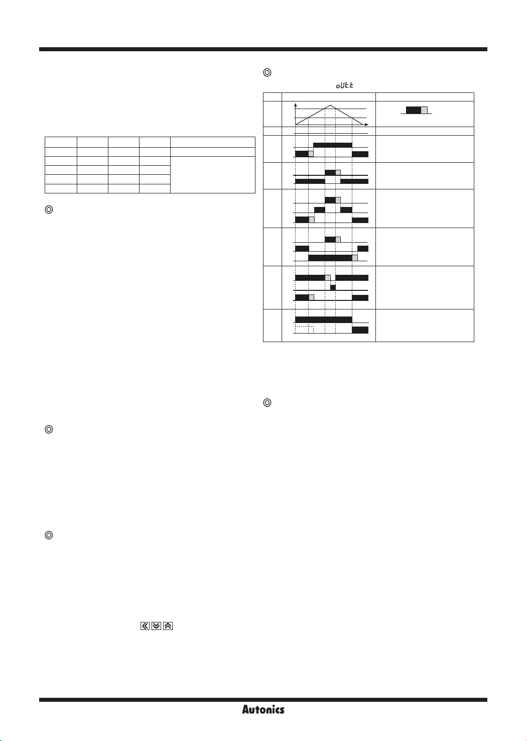
Preset output Mode
[PA 2 group: mo d e ]
Mode Output operation Operation
H: Hysteresis
OFF
GO
lST
LO
H
HI
hST
GO
HI
LhST
GO
LO
HI
HhST
GO
LO
HI
GO
LlST
LO
GO
LdST
LO
※
"H" means hysteresis and able to set 1 to 99 at "
H
H
H
H
H
H
H
No output
If it is equal or smaller than low
setting value, LO output will be ON.
If it is bigger than low setting value,
GO output will be ON.
If it is equal or bigger than high
setting value, HI output will be ON.
If it is equal or smaller than high
setting value, GO output will be ON.
If it is equal or smaller than low
setting value and equal or bigger
than high setting value, the output
will be ON. If it is bigger than Low
setting value and smaller than high
setting value, GO output will be ON.
If it is equal or bigger than low set
and equal or bigger than high set
value, output will be ON. If it is
smaller than low setting value and
high setting value, GO output will
H
be ON.
If it is equal or smaller than low
setting value, LO output will be ON.
If it is equal or smaller than high
setting value, HI output will be ON.
If it is bigger than low setting value
and High setting value, GO output
will be ON.
This operation is the same as
But it doesn't operate at initial low
set value, it will operate at next low
set value. If this is higher than low
set value, Go output will be ON.
in para-meter 2 among above comparison output chart.
※
Only
setting is available in MT4Y-☐-43 and MT4Y-☐-44
lST
models.
Sub output (Transmission function)
● RS485 communication output
It is able to set address (01 to 99)
It is able to transmit by selecting modulation speed
(Transmitted number of signal per 1sec.) of serial trans
-mission. (Selectable 1200, 2400, 4800, 9600bps)
● Low-speed serial output
It outputs current display value as Low-frequency (50Hz)
type.
● Current output (DC4-20mA)
It outputs DC4-20mA against High/Low-limit scale.
(Resolution: 12000 division)
● BCD output
It outputs display value as BCD Code..
※
Only one sub-output is selectable.
]
(More than one sub-output is not allowed.)
H
lST
" mode
HYS
L-44
Page 11
Multi Panel Meter
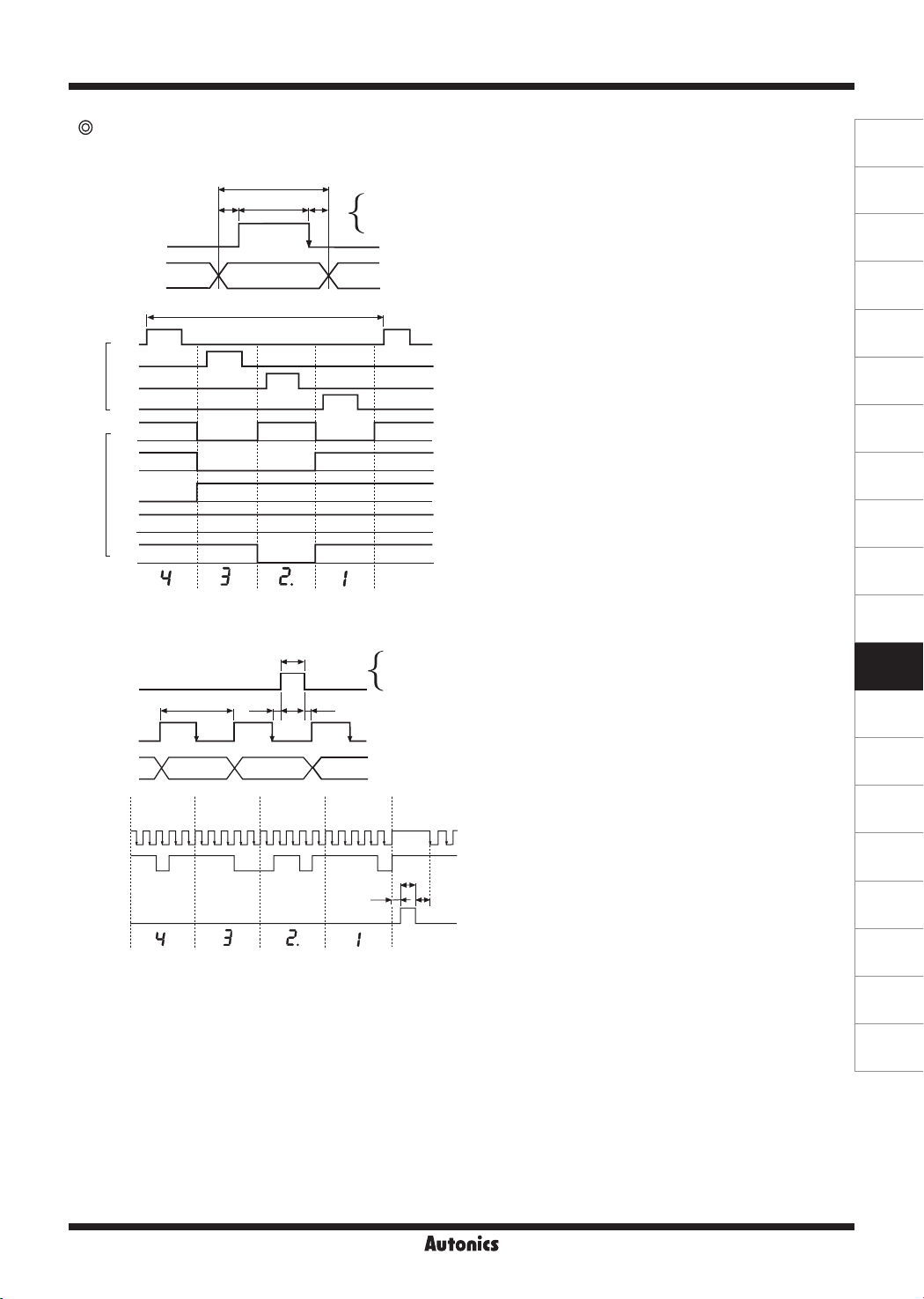
Time chart of BCD output and Serial output
● BCD output (Negative logic)
t
ta tw
tb
Digit signal
Input Data
Data
31.2ms
D3
D2
Digit
D1
D0
A
H L H L H
B
H L L H H
C
Data
L H H H H
D
H H H H H
Hdot
H L H H
Display
● Serial output (Negative logic)-Clock frequency:50Hz
t: 7.8ms
ta: 0.5ms
tw: 5ms
tb: 2.3ms
(A)
Photoelectric
Sensors
(B)
Fiber
Optic
Sensors
(C)
Door/Area
Sensors
(D)
Proximity
Sensors
(E)
Pressure
Sensors
(F)
Rotary
Encoders
(G)
Connectors/
Sockets
(H)
Temperature
Controllers
(I)
SSRs / Power
Controllers
(J)
Counters
(K)
Timers
Latch
Clock
Data
Input
ordering
Clock
Data
Latch
Display
tw
tb
Cn-1
tat
Cn C1
Dn-1 Dn D1
1 2 3 4 5
DP D C B A
H H L H H H H H L L L H H L H H H H H L
6 7 8 9 10
DP D C B A
11 12 13 14 15
DP D C B A
16 17 18 19 20
DP D C B A
t: 20ms
ta: 0.05ms
tw: 5ms
tb: 4.95ms
ta
*
(L)
Panel
Meters
(M)
Tacho /
Speed / Pulse
Meters
(N)
Display
Units
1
DP
tw
*
tb
*
(O)
Sensor
Controllers
(P)
Switching
Mode Power
Supplies
(Q)
Stepper Motors
& Drivers
& Controllers
(R)
Graphic/
Logic
Panels
(S)
Field
Network
Devices
(T)
Software
L-45
 Loading...