

Page 1
DRW160446AC
PULSE METER
MP5M SERIES
I N S T R U C T I O N M A N U A L
Please read the following safety considerations before use.
Safety Considerations
※
Please observe all safety considerations for safe and proper product operation to avoid hazards.
Safety considerations are categorized as follows.
※
Warning Failure to follow these instructions may result in serious injury or death.
Caution Failure to follow these instructions may result in personal injury or product damage.
※
The symbols used on the product and instruction manual represent the following
symbol represents caution due to special circumstances in which hazards may occur.
Warning
1. Fail-safe device must be installed when using the unit with machinery that may cause
serious injury or substantial economic loss. (e.g. nuclear power control, medical equipment,
ships, vehicles, railways, aircraft, combustion apparatus, safety equipment, crime/disaster
prevention devices, etc.)
Failure to follow this instruction may result in personal injury, fire, or economic loss.
2. The unit must be installed on a device panel before use.
Failure to follow this instruction may result in electric shock.
3. Do not connect, repair, or inspect the unit while connected to a power source.
Failure to follow this instruction may result in electric shock.
4. Do not disassemble or modify the unit. Please contact us if necessary.
Failure to follow this instruction may result in electric shock or fire.
5. Check the terminal numbers before connecting the power source and measurement input.
Failure to follow this instruction may result in fire.
Caution
1. Do not use the unit outdoors.
Failure to follow this instruction may result in electric shock or shortening the life cycle of the unit.
2. When connecting the power input or measuring input, make sure to tighten the terminal
screw bolt above 0.74N•m to 0.90N•m.
Contact failure may result in re.
3. Use the unit within the rated specications.
Failure to follow this instruction may result in electric shock or shortening the life cycle of the unit.
4. Do not use loads beyond the rated switching capacity of the relay contact.
Failure to follow this instruction may result in insulation failure, contact failure, contact bonding, relay
damage, or re.
5. Do not use water or oil-based detergent when cleaning the unit. Use dry cloth to clean the
unit.
Failure to follow these instructions may result in electric shock or re.
6. Do not use the unit where ammable or explosive gas, humidity, direct sunlight, radiant heat,
vibration, and impact may be present.
Failure to follow this instruction may result in re or explosion.
7. Keep dust and wire residue from owing into the unit.
Failure may result in re or product malfunction.
8. Check the polarity of the measurement input contact before wiring the unit.
Failure to follow this instruction may result in re or explosion.
Ordering Information
MP 5 M 4
Item
Product Description
5
※
The high-limit setting model(MP5M-
※
The above specications are subject to change and some models may be discontinued
without notice.
Thank you for choosing our Autonics product.
- N
Output
Power supply
Size
Digit
4
Main output (Comparative value output)
N Indicator
Relay single (high-limit) output+
1
NPN open collector output
Relay dual (
2
NPN open collector output
high
2 24VAC 50/60Hz, 24-48VDC
4 100-240VAC 50/60Hz
M DIN W72×H72mm
5 99999 (5-digit)
MP Pulse meter
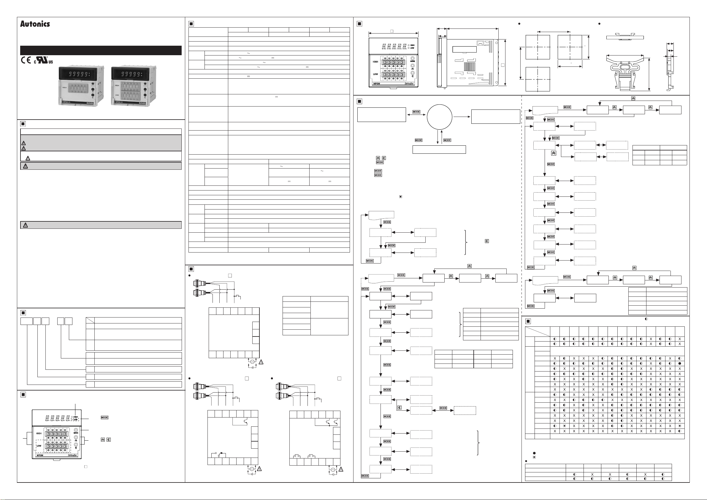
1: Display
Displays current value in RUN mode.
Alternately displays setting parameters and corresponding value in SETTING mode.
2: key
1
In RUN mode, press the key once to check max./
min. value.
In RUN mode, hold the key for over 2 sec to enter
2
parameter groups.
3: , key
3
4: Output status indicator
5: Thumbwheel switch for HIGH/LOW setting value
1) does not include the dotted line parts.
Select parameter groups, and select or setting
values in the corresponding parameters.
/low-limit) output+
Specications
Model
Display method 7-segment LED (zero blanking method)
Character size W4×H8mm
Display range -19999 to 99999
AC voltage 100-240VAC
Power
supply
AC/DC voltage 24VAC 50/60Hz, 24-48VDC
AC voltage Max. 9VA (100-240VAC 50/60Hz)
Power
consumption
AC/DC voltage Max. 6.5VA (24VAC 50/60Hz), Max. 5W (24-48VDC )
Permissible voltage range 90 to 110% of rated voltage
External power supply Max. 12VDC
Input frequency
Input method
Measurement range
Measurement accuracy
(23℃±5℃)
Display cycle OFF (for F2, F14 operation mode), 0.05, 0.5, 1, 2, 4, 8 sec (same as update output cycle)
Operation mode
Prescale function Direct input method (0.0001×10
Hysteresis
Relay single
Relay dual
Main
output
NPN open
collector
Memory retention Non-volatile memory (number of inputs: 100,000 operations)
Insulation resistance Over 100MΩ (at 500VDC megger)
Dielectric strength 2,000VAC 60Hz for 1 min
Noise immunity ±2kV the square wave noise (pulse width: 1㎲) by noise simulator
Mechanical 0.75mm amplitude at frequency of 10 to 55Hz in each X, Y, Z direction for 1 hour
Vibration
Malfunction 0.5mm amplitude at frequency of 10 to 55Hz in each X, Y, Z direction for 10 min
Mechanical 300m/s² (approx. 30G) in each X, Y, Z direction for 3 times
Shock
Malfunction 100m/s² (approx. 30G) in each X, Y, Z direction for 3 times
Mechanical
Relay
life cycle
Electrical
Ambient temp. -10 to 50℃, storage: -20 to 60
Environment
Ambient humi. 35 to 85%RH, storage: 35 to 85%RH
Approval
※
2
Weight
※
1: Setting range will vary depending on the decimal point.
※
2: The weight includes packaging. The weight in parenthesis is for unit only.
※
Environment resistance is rated at no freezing or condensation.
Connections
Indicator (MP5M- N)
INA
MP5M-2N MP5M-4N MP5M-21 MP5M-41 MP5M-22 MP5M-42
Indicator High-limit setting High/Low-limit setting
50/60Hz
±10% 80mA
Solid state input 1: Max. 50kHz (pulse width: min. 10㎲)
·
Solid state input 2: Max. 5kHz (pulse width: min. 100㎲)
·
※For F7, F8 operation mode, max. 1kHz (pulse width: min. 500㎲)
Contact input: Max. 45Hz (pulse width: min. 11ms)
·
[Voltage Input] High: 4.5-24VDC , Low: 0-1VDC, input impedance: 3.9kΩ
[No-voltage Input]
·Operation
·Operation
·Operation
·Operation
·Operation
·Operation
Frequency/Revolutions/Speed (F1), Passing speed (F2), Cycle (F3),
Passing time (F4), Time interval (F5), Time differential (F6), Absolute ratio (F7),
Density (F8), Length measurement 1 (F9), Interval (F10), Accumulation (F11),
Addition/Subtraction-individual input (F12), Addition/Subtraction-phase difference
input (F13), Length measurement 2 (F14)
-
-
-
-
ᜢ ᜧ
Approx. 243g (approx. 168g) Approx. 256g (approx. 181g) Approx. 265g (approx. 190g)
Black
Black
Brown
+12V
INB 0V
8110312
9211413614
mode F1, F2, F7, F8
mode F3, F4, F5, F6
mode F9, F10, F11, F14
mode F12, F13
mode F1, F2, F7, F8
mode F3, F4, F5, F6
Blue
HOLD/
※
1
RESET
Short-circuit impedance: Max. 80Ω, Residual voltage: Max. 1VDC,
Open-circuit impedance: Min. 100kΩ
: 0.0005Hz to 50kHz
: 0.01 to max. of each time range
: 0 to 99999
: -19999 to 99999
: F.S.±0.05%rdg±1-digit
: F.S.±0.01%rdg±1-digit
-9
to 9.9999×10⁹)
※
1
0 to 9999
250VAC 3A resistive load 1c
-
Max. 30VDC
Min. 5,000,000 operations
Min. 100,000 operations (250VAC 3A resistive load)
℃
100mA Max. 30VDC 100mA ×2
※
1: Operation mode F1 to F10
: Display value HOLD
Operation mode F11 to F14
: Display value RESET
※
2:
Model Source
MP5M-21
MP5M-22
MP5M-2N
15
16
MP5M-41
MP5M-42
MP5M-4N
250VAC 3A resistive load 1a
×2
24-48VDC
24VAC 50/60Hz
100-240VAC
50/60Hz
17
5
7
+-
※
2
High-limit setting (MP5M- 1)
SOURCE
Black
Black
Brown
Blue
HOLD/
※
INB 0V
INA
+12V
8110312
9211413614
CONTACT OUT:
250VAC 3A
RESISTIVE LOAD
RESET
5
1
High
SOURCE
15
16
17
7
+-
High/Low-limit setting (MP5M- 2)
Black
Black
Brown
INB 0V High Low
INA
+12V
8
10312
9211413614
H L
1
CONTACT OUT:
250VAC 3A
※
2
RESISTIVE LOAD
Blue
HOLD/
RESET
5
※
1
SOURCE
15
16
17
7
+-
※
2
Dimensions
72
14.3
11.8
75
67.5
Parameter Groups
Parameter 0 group
(Max./Min. monitoring value)
RUN
mode
2 sec
Terminal
input
11-12
3 sec
HOLD/RESET
※
Input
※
Operation mode F1 to F10
: Display value HOLD
Operation mode F11 to F14
: Display value RESET
Parameter 1/2/3 group
※
Press the
※
Press the
next parameter.
※
Hold the
※
Hold the
setting value.
※
If there is no key input for 60 sec while setting the parameters, the new settings are ignored, and the
unit will return to RUN mode with previous settings.
※
The dotted line parameters may not appear depending on output specications or other parameter
settings. Please refer to ' Operation mode by parameter group'.
※
1: Each parameter and corresponding setting value will ash alternately every 0.5 sec.
, keys to select or set the desired value.
key once after
key for
key for
changing the setting value, to save the setting value and move to the
1.5 sec at any parameters to return to the select parameter group mode.
3 sec to save the setting value and return to RUN mode after changing the
● Parameter 0 group
RUN mode
Flashes
※
1
hPEK
lPEK
alternately
99999
`9999
Max. monitoring
value
Min. monitoring
value
※
Resetting monitoring value
: Hold the key for over 2 sec.
(reset current value)
● Parameter 1 group
Flashes
alternately
2 sec
※
1
PARa1
Operation mode
ㄹF1
●Setting range: F1 to
NPnhF
NPnhF
STARD
fDEFY
Sensor type of
input A
Sensor type of
input B
Output mode
●Setting range
Parameter Output mode Parameter Output mode
STARD
OUT-H
OUT-L
※
Only appears in high/
Output hysteresis
●Setting range:
0001
the setting range varies depending on the decimal point setting
(
※
Only appears in high-limit setting models,
high/low-limit setting models.
L comparative output
※
Only appears in high/
STArT
Start compensation timer function & compensation time
●Setting range: )0 to
※
Only appears in high/
999(9
999(9
Auto-zero time for input A
Auto-zero time for input B
Memory retention
OFF
●Setting range:
PARa2
F14
●Setting range
Parameter Input sensor type
NPnhF
NPnmF
NPnlF
PNphF
PNpmF
PNplF
S (Standard)
H (High)
L (Low)
to
0000
limit
9(9
(sec)
9(9
low-limit
setting models.
,
ㄹㄹON
OFF
NPN solid state input 1
NPN solid state input 2
NPN contact input
PNP solid state input 1
PNP solid state input 2
PNP Contact input
OUT-B
OUT-I
OUT-F
low-limit
9999
low-limit
●
PARa3
B (Block)
I (One-shot)
F (Deection)
setting model.
setting models.
Setting range:
to
)1
999(9
(sec)
RUN mode
3 sec
MODE
IN-A
IN-B
OUT-T
HYS
GUARD
AUToA
AUToB
MEMO
Panel Cut-out Dimensions Bracket
Min. 91
0.7
0
68
0.7
68
Min. 91
0
● Parameter 2 group
Flashes
alternately
2 sec
※
1
PARa1 PARa2
00000
Decimal point location of display value
●Setting range:
tSEC
RUN mode
3 sec
DOT
tUNT
tMIN
Time unit and range
PScaH
^0000
PScaY
PScbH
^0000
PScbY
DISpT
COUnB
● Parameter 3 group
RUN mode
Flashes
alternately
LOC
3 sec
Operation Mode By Parameter Groups
Operation
mode
Parameter
0 group
1 group
)
2 group
3 group
※
1: Only appears in high/low-limit setting models.
※
2: Only appears in high-limit setting models, high/low-limit setting models.
※
3: The settings for
※
4: (
※
5: ( ) setting range:
Monitoring delay function by output mode
Output mode S mode H mode L mode B mode I mode F mode
Parameter
Comparative output limit
Start compensation timer
F1 F2 F3 F4 F5 F6 F7 F8 F9 F10 F11 F12 F13 F14
hPEK
lPEK
MODE
IN-A
※
1
IN-B
※
2
OUT-T
※
1
HYS
GVARD
AVToA
AVToB
MEMO
DOT
tUNT
PScaH
PScaY
PScbH
PScbY
DISpT
ㄹCOUnB
LOC
) F output mode[
IN-B
OUT-F
OFF, )05, )5, 1, 2, 4, 8
99999
2 sec
※
1
※
5
and
are applied.
IN-A
] cannot be set.
STARD OVT-; OVT-L OVT-B OVT-I OVT-F
Prescale mantissa (X) of input A
●Setting range:
Prescale exponent (y) of input A
10 01
●Setting range:
Prescale mantissa (X) of input B
●Setting range:
Prescale exponent (y) of input B
10 01
●Setting range:
Display cycle of measurement value
●Setting range:
)05
※
Setting range in operation mode F2, F14
:
OFF, )05, )5, 1, 2, 4, 8
Setting value of Input B
●Setting range: 1 to
PARa1 PARa2 PARa3
Lock
OFF
●Setting range:
Appears in all operation modes(F1 to F14).
Appears in all operation modes(F1 to F14).
46
00000, 000)0, 00)00, 0)000, )0000
99(99
99(99
●Setting range
(sec)
tSEC
99(99
999(9
99999
to
)0001
(9999
-9
(10
10 - 9
)0001
10 - 9
)05, )5, 1, 2, 4, 8
) to
to
(9999
-9
(10
) t
(sec)
99999
Parameter Function
OFF
LOc0
LOc1
LOc2
LOc3
(unit: mm)
8.3
7.3
4
40.7
PARa3
(min)
tMIN
999.99s
9999.9s
99999s
10 09
o 10 09
(sec)
Unlock
Locks all
Parameter 1, 2, 3 lock
Parameter 2, 3 lock
Parameter 3 lock
( : parameter display,
X: no parameter display)
99(99
999(9
99999
(109)
(109)
999.99m
9999.9m
99999m
※
3
※
4
Page 2
Input Specications
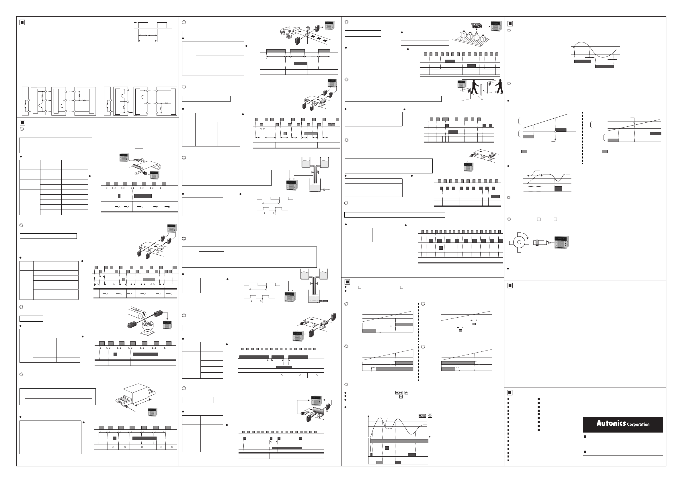
1. Input signal
Standard duty ratio of input signal is 1:1.
(1) Solid state input 1
Input frequency: max. 50kHz (ON/OFF pulse width: min. 10
(2) Solid state input 2
Input frequency: max. 5kHz (ON/OFF pulse width: min. 100
※
For F7, F8 operation mode, max. 1kHz (ON/OFF pulse width: min. 500㎲ of each)
(3) Contact input
Input frequency: max. 45Hz (when each ON/OFF pulse width is over 11ms)
①
Contact specications: 12VDC, stable switching of load current as small as 5mA
②
2. Input type [
MP5M allows selection between NPN input(solid state/contact) or PNP input(solid state/contact).
(1) NPN input type (2) PNP input type
Contact
①
Operation Modes [
F1 Mode: Frequency/Revolutions/Speed
Measures the frequency of input A and displays the calculated frequency, revolutions, and speed.
1) Frequency(Hz) = f × α (α= 1[sec])
2) Revolutions(rpm) = f × α (α= 60[sec])
3) Speed(m/min) = f × α (α= 60L[sec])
NPN voltage
②
output type sensor
Sensor circuit
IN-A, IN-B
NPN open collector
③
output type sensor
Sensor circuit
]
+12V
IN
0V
(COM)
MP5M
3.9kΩ
MODE
Contact
①
Sensor circuit
]
※
L: travel distance of conveyor belt of 1 cycle [m]
α: prescale value
For multiple objects, α =
N
ON
OFF
of each)
㎲
of each)
㎲
PNP voltage
②
output type sensor
Sensor circuit
ON OFF
※
T: Single cycle
PNP open collector
③
output type sensor
Sensor circuit
60L
T
of input signal
+12V
IN
0V
(COM)
Display value and display unit
Display
value
Frequency
Revolutions
Speed
Display unit
Hz 1
kHz 0.001
rps 1
rpm (default) 60
mm/sec 1,000L
cm/sec 100L
m/sec 1L
m/min 60L
km/hour 3.6L
F2 Mode: Passing Speed
Displays the passing speed between input A ON and input B ON.
Passing speed (V) = f × α (α = L[m])
※
f : reciprocal of time [sec] between input A (sensor) ON and
input B (sensor) ON.
L: distance between input A (sensor) and input B (sensor) [m]
α: prescale value
Display value and display unit
Display
Display
value
unit
mm/sec 1,000L
cm/sec 100L
m/sec
(default)
m/min 60L
Passing speed
km/hour 3.6L
α
(prescale value)
α
(prescale value)
1L
MP5M
Timing chart
Input A
t1 t2 t3 t4 t5 t6
Hold
Input
1
Display
t1
1
α
t2
Sensor B
α
Timing chart
Input A
Input B
Hold
input
t1tat2 t3 t4 t5 t6 t7
Display
※
ta: Return time(over 20ms)
1
1
α
t1
1
α
t2
t3
Encoder
1
t3
α
1
α
t5
MP5M
Sensor A
1
1
α
t6
t4
F3 Mode: Cycle
Displays the measured time from Input A ON to the next ON.
Cycle(T) = t
Display value and display unit (
Display
Display unit
value
SEC MIN
999.99s
(default)
Cycle
9999.9s 9999.9m
99999s 99999m
※
t: measurement time[sec]
[
tUNT
Timing chart
999.99m
Input A
Display
] of
parameter 2
Hold
input
)
Photoelectric
sensor
t1
t2
t3 t4 t5 t6
t1 t2
t3 t5 t6
F4 Mode: Passing Time
Measures the time from Input A ON to the next ON, and displays the passing time of the arbitrary
distance.
Passing time[sec]= t × α
L [m]
(α=
Distance advanced in 1 pulse cycle [m]
※
t : measured time[sec], L : arbitrary distance[m
α: prescale value
Display value and display unit (
Display
Display unit
value
SEC MIN
999.99s
(default)
9999.9s 9999.9m
Passing time
99999s 99999m
999.99m
[
] of
tUNT
Timing chart
Input A
Hold
input
Display
)
]
parameter 2
t1
)
t2
t3 t4 t5 t6
αt2α
t1
L : Distance[m]
α
t3
Pulse width
MP5M
3.9kΩ
MP5M
1
α
α
t6
1
α
t7
MP5M
MP5M
α
t5
t6
F5 Mode: Time Interval
Displays measured time of Input A ON
Time interval(T) = t ※t: measured time of input A ON [sec]
Display value and display unit (
Display
Display unit
value
SEC MIN
999.99s
(default)
9999.9s 9999.9m
Time interval
99999s 99999m
999.99m
[
] of
tUNT
parameter 2
Timing chart
Input A
Hold
input
Display
※
ta: return time (over 20ms)
)
Motor
t1
t2 t3
t1 t2
F6 Mode: Time Differential
Displays measured time from Input A ON to Input B ON.
Time differential(T) = t(ta to tb)
※
t(ta to tb): measured time from input A ON to input B ON [sec]
Display value and display unit (
Sensor circuit
Display
Display unit
value
SEC MIN
999.99s
(default)
Time
9999.9s 9999.9m
difference
99999s 99999m
999.99m
[
] of
tUNT
Timing chart
Input A
Input B
Hold
input
Display
※
ta: return time (over 20ms)
parameter 2
ta
t1 t3 t5 t6 t7
t1 t2 t3 t4 t6 t7
Sensor B
)
t4t2
F7 Mode: Absolute Ratio
Measures and displays relative speed, amount, speed, etc.
of input B against input A in percentage (%).
Absolute ratio = (Input B / Input A) × 100%
Absolute ratio =
Frequency of input A[Hz] × Aα
※
Aα: Prescale value of input A, Bα: Prescale value of input B
Display value and display unit
Display
value
Absolute
ratio
※
Hold: When the hold signal turns ON, the display value is maintained until the display cycle turns to
Frequency of input B[Hz] × Bα
Display unit
%
Display =
Frequency of input A[Hz] × Aα
hold OFF.
× 100[%]
Timing chart
Input A
Input B
Frequency of input B[Hz] × Bα
fA
fB
MP5M
× 100[%]
F8 Mode: Density
Measures and displays the density ratio (%) of input B against the total sum of input A and input B.
Input B
Density =
Input A + Input B
Frequency of Input B[Hz] × Bα
Density =
(Frequency of input A[Hz] × Aα) + (Frequency of input B[Hz] × Bα)
※
Aα: Prescale value of input A, Bα: Prescale value of input B
× 100[%]
× 100[%]
Display value and display unit
Display
value
Density %
α
※
Measure and display the number of input A pulses during input B ON.
Length measurement = P × α
※
Display unit
Hold: When the hold signal turns ON, the display value is maintained until the display cycle turns to
hold OFF.
F9 Mode: Length Measurement 1
P: Number of input A pulses, α: Prescale value
Timing chart
Input A
Input B
fA
MP5M
fB
Input A
Input B
Display value and display unit
Display
value
Display unit
Quantity
(default)
mm
Length
cm
measurement
m
Timing chart
Input A
1 5 2 33 12 6
Input B
Hold
input
Display
※
ta, tb: return time(over 20ms)
ta
MP5M
44 1 2
tb
6
α 2 α 4 α
F10 Mode: Interval
Measures and displays the number of input A pulses from Input B ON to the next ON.
Interval = P × α
※
P: Number of input A pulses, α: Prescale value
Display value and display unit
Display
value
Interval
α
Display unit
Quantity
(default)
mm
cm
m
Timing chart
Input A
Input B
Display
※
1 1 153 3 32 2 24 4
Hold
input
ta: return time(over 20ms)
ta
5×α 4×α
Stamp
tata
MP5M
Sensor A
Flow meter B Flow meter A
Liquid
Flow meter B Flow meter A
Liquid
Photoelectric
sensor
Photoelectric
sensor
MP5M
MP5M
F11 Mode: Accumulation
Measures and displays the counted value of input A pulses.
Accumulation = P × α
※
P: Number of input A pulses,
α: Prescale value
Operation
Counts the number of input A pulses.
①
Input B is an enable input signal.
②
During ON, the quantity and display
value of input A will be held, and
during OFF input A will be re-counted.
When RESET input is ON, the integrated
③
t3
counted value will be reset to "0".
Display value and display unit
Display value Display unit
Accumulation Quantity[EA]
Timing chart
Input A
Input B
RESET
Display10 01 12 23 34 4
※
5
5
6
F12 Mode: Addition/Subtraction-Individual Input
Displays the counted value from added input A pulses
and subtracted input B pulses. When there are two inputs
simultaneously, it will not count.
Addition/Subtraction = Input A × α - Input B × β
※
α: Prescale value of input A, β: Prescale value of input B
Display value and display unit
Display value Display unit
Addition/Subtraction
(individual input)
Quantity
F13 Mode: Addition/Subtraction-
Phase difference input
When input A is low, counting is added to the low of input B.
When input A is low, counting is subtracted from the high of input B.
Addition/Subtraction(phase difference)
= Detects position and speed using A and B phases of
encoder outputs as input.
Display value and display unit
Display value Display unit
Up/Down counting
(phase difference
input)
Quantity
F14 Mode: Length Measurement 2
Measures and displays the number of pulses from input A until the value of input B reaches the set value.
Length measurement 2 = P × α (until the setting value of Input B)
※
P: Number of input A pulses, α: Prescale value
Display value and display unit
Display value Display unit
Length
measurement 2
※
If input A and input B are ON during
initial power supply, it will not count
and only count the number of rising
edge.
※
Display value is renewed depending
on the display cycle [
※
1: When the display cycle[
value of input B reaches the setting value B[
Output Modes [
MP5M- 1: S output mode, MP5M- 2: S, B, H, L, I, F output mode
Requirement for setting comparative value: (B output mode) L<H, (F output mode) L<H,
(other output modes) individual output operation regardless of size or order of set comparative values.
※
1: hysteresis
S
(Standard) Output Mode [
Quantity[EA]
DISpT
B (Block) Output Mode [
Comparative
H
value
L
H
Output
L
H output : Comparative value H ≤ Display value
L output : Comparative value L ≥ Display value
※
1
H (High) Output Mode [
H
Comparative
value
L
H
Output
H output : Comparative value H ≤ Display value
L output : Comparative value L ≤ Display value
F(Deflection) Output Mode [
Transmits outputs when the saved setting value exceeds H deviation or L deviation.
Saving setting value: Press the +
Checking setting value: Press the key to check the setting value.
Setting deviation: Based on the setting value, set H deviation, L deviation by the thumbwheel switches.
Deviation setting range: 0.0001 to 99999 (setting range depends on the decimal point [
H deviation
Setting value
Power
Saving
setting value
L deviation
output
H deviation
output
L
(high-limit)
(low-limit)
L deviation
ON
OFF
ON
OFF
ON
OFF
ON
OFF
※
1
(the set deviation value is saved during Power OFF until it is re-set.)
E.g.) Decimal point[
Saving setting value( + key)
※
2
※
3
Operation and timing chart
Pulse of input A is added, and pulse of input B is subtracted.
Input A
Input B
RESET
Display
Display
] setting.
] setting is
DISpT
OUT-T
STARD
OVT-B
※
1
OVT-H
]
※
1
OVT-F
H
Input A
L
H
Input B
L
H
RESET
L
Display
0 01 2 2 2 23 1 13
※
α, β=1 display value
Timing chart
H
Input A
L
H
Input B
L
H
RESET
L
Display
Timing chart
H
L
1 2 41
H
L
H
L
1
2
0
※
1
, it will maintain the quantity of input A until the
OFF
COUnB
]
I (One-shot) Output Mode [
]
]
keys to save as setting value.
※
Comparative
value
Output
H output : Comparative value H ≤ Display value
L output : Comparative value L ≤ Display value
L (Low) Output Mode [
Comparative
value
Output
H output : Comparative value H ≥ Display value
L output : Comparative value L ≥ Display value
]
]: "0000.0", Setting range: 0.1 to 9999.9
DOT
MP5M
Photoelectric
sensor
0 01 1 12 2 23 0
(e.g.) setting value of Input B=4
3
1
2 10
0
].
No hysteresis for I output mode
H
L
H
L
Input A
3 32 2
3
0.3 sec(fixed)
Input A
(addition)
Input B
7
6
OVT-L
H
L
H
L
※
※
※
※
1
2: When selecting initial comparative
output limit function, it does not
transmit outputs.
3: The graph is assuming that there
is a saved setting value prior to the
setting value save point. The actual
output position may be different.
The deviation can be set to "0" but the
actual operation will be the same as "1".
MP5M
α=1 display value
33 12 6
Input B
(subtraction)
MP5M
1
24 4 30 5 4 5
7
OVT-I
]
0.3 sec(fixed)
]
※
1
] setting.)
DOT
Function
Hysteresis [
Near the comparative setting value, the output may turn ON/OFF frequently and unstably.
To prevent this, the hysteresis value is set based on the comparative setting value.
44 2
※
A: hysteresis value
※
The hysteresis value can be set to "0" but the actual operation value is "1".
Delay Monitoring [
After supplying power, the starting current of motors and other inputs are changeable. This function
allows stable control by limiting all outputs for a certain period of time, until the target measurement
unit stabilizes. It may also control L outputs until a specific output is reached.
Comparative output limit function [
: Limits L output before H output.
1)During S(Standard), B(Block) output mode 2)During F(Deflection) output mode
value
Comparative
Output
※
After supplying power, there is no initial L comparative
output
※
Each setting value of H, L is not related to their relative sizes. Hence, H value may be lower or equal to L
value.
Start compensation timer function[
L output
Auto-zero Time Setting [
When there is no input signal during auto-zero setting time, the display value is automatically set to
0(zero). Please set the auto-zero setting time so that it is longer than the interval of the slowest input
signal. If the setting time is too long and there is no input signal, the rate at which the display value
falls to 0(zero) decrease, and output response rate may slow down.
Prescale[
Displays values in required units or specific multiples by counting the number of input pulses, then
multiplying the number of pulses or the length of pulses by variables(X×10y).
Setting prescale value(α=15)
Set mantissa(X) as 1.5000, and exponent(Y) as 1 for prescale value(α)=15.
The same display value can be obtained with α value set as X=0.1500, and Y=2.
Cautions During Use
1. Please separate the unit wiring from high voltage lines or power lines to prevent inductive noise.
2. Install a power switch or circuit breaker to control the power supply.
3. In case of 24VAC, 24-48VDC model, power supply should be insulated and limited voltage/current
or Class 2 SELV power supply device.
4. The power switch or circuit breaker should be installed where it is easily accessible by the user.
5. Storing the unit
When storing the unit for an extended period, please avoid direct exposure to sunlight. Ambient
temperature should be between -20℃ to 60℃ and ambient humidity should be between 35% to
85%RH. Store in factory packaging for best results.
6. Input line
Please use a shield wire in environments where noise may occur or instances where long
measurement input lines are required.
7. Please maintain distance between the power supply line and measurement input line.
8. Do not use the unit in the following environments.
Environments with high vibration or shock.
①
Environments with exposure to direct sunlight.
②
Near machinery which produce strong magnetic force or electric noise.
③
9. This product may be used in the following environments
Indoors
①
Max. altitude: 2,000m
②
Pollution degree 2
③
Installation category II
④
※
Failure to follow these instructions may result in product damage.
Major Products
Photoelectric Sensors Temperature Controllers
Fiber Optic Sensors Temperature/Humidity Transducers
Door Sensors SSRs/Power Controllers
Door Side Sensors Counters
Area Sensors Timers
Proximity Sensors Panel Meters
Pressure Sensors Tachometer/Pulse (Rate) Meters
Rotary Encoders Display Units
Connectors/Sockets Sensor Controllers
Switching Mode Power Supplies
Control Switches/Lamps/Buzzers
I/O Terminal Blocks & Cables
Stepper Motors/Drivers/Motion Controllers
Graphic/Logic Panels
Field Network Devices
Laser Marking System (Fiber, Co₂, Nd: YAG)
Laser Welding/Cutting System
HYS
]
Comparative setting value H
Comparative setting value L
GUArD
H
L
H
L
Comparative output limit
function removal
( ).
Monitoring delay time
L
No output
PSc
.H, PSc .Y
A
Output H
Output L
A
]
]: Only for S(Standard), B(Block), F(Deflection) output mode.
fDEFY
Comparative output limit
function removal
H deviation
Setting value
value
L deviation
]
STArT
Set monitoring delay time so that there is
no output during the delay time.
AUToA, AUToB
Comparative
※
※
]
H
output
L
After supplying power, there is no comparative output of L
deviation
( ).
H and L deviation are not related to their relative sizes.
(H deviation setting value > L deviation setting value,
H deviation setting value < L deviation setting value)
]
Number of revolutions(rpm) = f×α
MP5M
※
f: The number of input pulses per second[Hz],
α: Prescale value
N: The number of pulses per revolution
= f×60×(1 / N)
= f×60×(1 / 4)
= f×60×0.25
= f×15
http://www.autonics.com
HEADQUARTERS:
18, Bansong-ro 513beon-gil, Haeundae-gu, Busan,
South Korea, 48002
TEL: 82-51-519-3232
E-mail: [email protected]
DRW160446AC
 Loading...