

Page 1
DRW170811AB
Autonics
2-Phase Unipolar Intelligent Stepper Motor Driver
MD2U-ID20
I N S T R U C T I O N M A N U A L
Please read the following safety considerations before use.
Safety Considerations
00
Please observe all safety considerations for safe and proper product operation to avoid
※
hazards.
symbol represents caution due to special circumstances in which hazards may occur.
※
Warning
Caution
Ii
Warning
A
1. Fail-safe device must be installed when using the unit with machinery that may
cause serious injury or substantial economic loss. (e.g. nuclear power control,
medical equipment, ships, vehicles, railways, aircraft, combustion apparatus, safety
equipment, crime/disaster prevention devices, etc.)
Failure to follow this instruction may result in fire, personal injury, or economic loss.
2. Do not connect, repair, or inspect the unit while connected to a power source.
Failure to follow this instruction may result in fire.
3. Install the unit after considering counter plan against power failure.
Failure to follow this instruction may result in personal injury, or economic loss.
4. Check 'Connections' before wiring.
Failure to follow this instruction may result in re.
5. Do not disassemble or modify the unit.
Failure to follow his instruc ion may result in fire.
6. Install the driver in the housing or ground it.
Failure to follow his instruc ion may result in personal injury, or fire.
7. Do not touch the unit during or after operation for a while.
Failure to follow this instruction may result in burn due to high temperature of the surface.
8. For rotating the motor manually when turning off the power, separate the motor and
the driver.
Power may be supplied to he driver.
9. Emergency stop directly when error occurs.
Failure to follow this instruction may result in re, or personal injury.
Caution
1. When connecting the power input, use AWG 18(0.75mm2) cable or over.
2. Install over-current prevention device (e.g. the current breaker, etc) to connect the
driver with power.
Failure to follow this instruction may result in fire.
3. Check the control input signal before supplying power to the driver
Failure to follow this instruction may result in personal injury or product damage by
unexpected signal.
4. Install a safety device to maintain the vertical position after turn off the power of this
driver.
Failure to follow this instruction may result in personal injury or product damage by releasing
holding torque of the motor.
5. Use the unit within the rated specications.
Failure to follow this instruction may result in fire or product damage.
6. Use dry cloth to clean the unit, and do not use water or organic solvent.
Failure to follow his instruc ion may result in fire.
7. Do not use the unit in the place where ammable/explosive/corrosive gas, humidity,
direct sunlight, radiant heat, vibration, impact, or salinity may be present.
Failure to follow this instruction may result in re or explosion.
8. The driver may overheat depending on the environment.
Install the unit in the well ventilated place and forced cooling with a cooling fan.
Failure to follow this instruction may result in product damage and degrada ion.
9. Keep metal chip, dust, and wire residue from owing into the unit.
Failure to follow this instruction may result in re or product damage.
10. Use the designated motor only.
Failure to follow this instruction may result in re or product damage.
※
The above specications are subject to change and some models may be discontinued
without notice.
※
Be sure to follow cautions written in the instruction manual and the technical
descriptions (catalog, homepage).
Thank you for choosing our Autonics product.
Failure to follow these instructions may result in serious injury or death.
Failure to follow these instructions may result in personal injury or product damage.
.
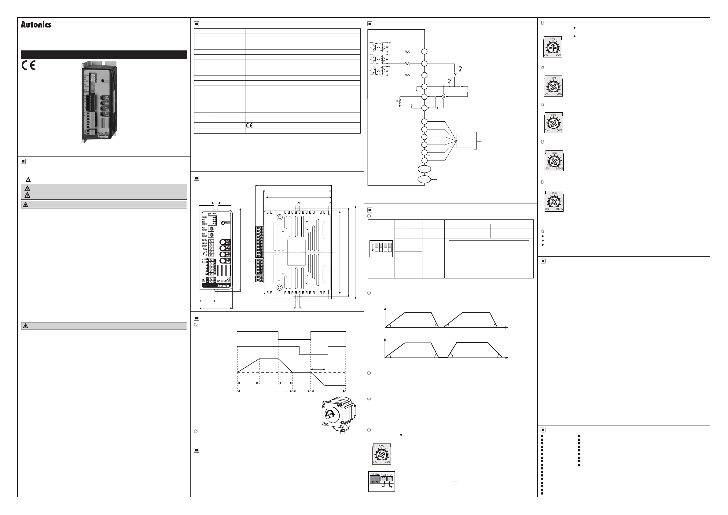
Specications I/O Circuit and Connections
Model MD2U-ID20
Power supply
Allowable voltage range 90 to 110% of rating voltage
Max. current consumption
RUN current
STOP current 20 to 70% of RUN current (set by STOP current volume)
RUN method Unipolar constant current drive type
Basic step angle 1.8˚/step
Max. drive speed 1500rpm
Input resistance 3.3kΩ (CW/CCW, RUN/STOP, HOLD OFF)
Insulation resistance
Dielectric streng h 1000VAC 50/60Hz for 1 minute (between all terminals and case)
Noise immunity
Vibration
Shock 300m/s² (approx. 30G) in each X, Y, Z direction for 3 times
Environ-
ment
Approval
Weight
※
1: Since torque characteristics are improved but the driver temperature rises with the 30VDC
power supply, he driver should be installed at the well ventilated environment.
Torque is variable by power supply.
※
2: Based on the ambient temperature 25℃, ambient humidity 55%RH.
※
3: RUN current varies depending on the input RUN frequency, and the max. instantaneous
RUN current varies also.
※
4
: The weight includes packaging. The weight in paren hesis is for unit only.
※
Environment resistance is rated at no freezing or condensation.
Dimensions
1~
1
※
3
※
Ambient temp. 0 to 50℃, storage: -10 to 60℃
Ambient humi. 35 to 85%RH, storage: 35 to 85%RH
4
※
4.5
24-35VDC
2
※
3A
0.5-2A/Phase
Over 200MΩ (at 500VDC megger, between all terminals and case)
±500V the square wave noise (pulse width:1㎲) by the noise simulator
1.5mm amplitude at frequency of 10 to 55Hz (for 1 min) in each
X, Y, Z direction for 2 hours
Approx. 303g (approx. 190g)
ᜡ
86
76.5
74
38
(unit: mm)
Inner power (24-35VDC)
V
3.3kΩ
3.3kΩ
3.3kΩ
RUN speed
※
Inner adjuster is correlated to external adjuster control and external voltage control.
1:
Make sure that inner adjuster must be set to maximum in order to set maximum Run
speed using external adjuster and external voltage.
5VDC(Inner)
1
2
3
4
5
6
1
2
3
4
5
6
DC+
Power
DC-
Functions
Function DIP Switch
No. Name Function
SYM/
1
NORMAL
2 MS2
100
20
39 5
4.5
94
100
ON 1 3 42
105
※
1: D=Don't care
※
Reboot the driver after changing function selection switch.
Selection of Symmetry/Asymmetry
※
The function to make the ACC/DEC time of run-speed as asymmetry or symmetry using
DIP switch No. 1.
Speed
(rpm)
3 MS3
H/L
4
SPEED
SYM/
NORMAL
Max. speed
High/Low
speed
Asymmetry (Normal) of accel/deceleration
Time Chart
High Speed mode
RUN/STOP
CW/CCW
Rota ion speed
and direction
(symmetry mode)
※
It accelerates up to RUN speed during ACC time
after RUN signal is ON and decelerates during DEC time
after it is OFF.
※
It is disable to change he direc ion during the signal is ON.
※
It takes 0.5sec for deceleration when DEC time is "0%".
Low speed mode
Max. RUN speed is 150rpm and ACC and DEC time are not available.
It is same with High speed to change RUN/STOP and direction.
Troubleshooting
00
1. When the motor does not rotate
Check the connec ion of controller and driver.
①
2. When motor rotates to the reverse direction
Check the DIR input of
①
DIR input is [ON] for CW, and [OFF] for CCW.
②
3. When operation of motor is unstable
Check whe her driver and motor are connected correctly.
①
Check whe her output current of the driver by current setting is proper for operation of
②
the motor.
ON
OFF
-r-=-
-
ON
OFF
,---_;
'
: : I
ACC time
-------------
he driver.
' '
. . I •
' '
,---~-
' : ' :
: ' :
______J_
DEC
:------.: : : : g
time
' ' '
~
' ' '
~I+---
ACC Time
(same as DEC time)
Motor
stop
' '
---:----_;
'
r-:,:
'
'
CCWCW
CW
I
-----
Speed
(rpm)
※
It is able to set the gradient (acceleration and deceleration time) as ACC/DEC time.
Selection of max. speed (MS2, MS3)
※
The function to select the max. speed of motors.
※
The max. speed of stepper motor is changed by MS2/MS3 and Hi/Low speed.
※
The features of run and vibration are able to change depending on MS2, MS3.
※
Lower the max. speed to run a motor smoothly.
Selection of H/L SPEED
※
H/L SPEED mode selection switch
: Accel/deceleration control is not available in Low speed mode since all sections are
included in Pull-in range.
※
Low speed mode: It is able to drive a motor up to 150rpm of max. drive speed.
※
High speed mode: It is able to drive a motor up to 1500rpm of max. drive speed.
Setting RUN current
RUN
CURRENT
A
V
ACC time and DEC time are repeated as a asymmetrical gure
Symmetry of accel/deceleration
A
V
ACC time and DEC time are repeated as a symmetrical gure
RUN current setting is for the current provided to the motor in running status.
•
When RUN current is increased, RUN torque of the motor is also increased.
※
When RUN current is set too high, the heat of the motor is increased.
※
Set RUN current properly for the load within the rated current range of the
※
motor.
※
RUN current setting range: 0.5 to 2.0A
※
RUN current setting method: Measure he voltage by connecting a
2 0A0.5A
DC voltage meter to both CT+ and CT- terminals while the motor is
running (max. 150rpm).
E.g.) Input voltage (3V) ×
3
Change RUN current only when the motor stops.
CT CT
※
RUN/STOP
CW/CCW
HOLD OFF
COM
※External adjuster control
Inner adjuster control
A-com
B-com
A
A
B
B
+
24-35VDC
-
Switch position
ON OFF
Symmetry Asymmetry
D
\/
D
\
0-5VDC
+
※External voltage control
2kΩ (1 to 3kΩ)
Motor
MS2 MS3 H/L SPEED
ON ON
ON OFF 1350
OFF ON 1000
OFF OFF 500
※
※
1
1
D
D
A
j
D
2
= 2A
(motor excitation current)
※
RUN/STOP signal input
→ [ON]: RUN, [OFF]: STOP
※
Direc ion signal input
→ [ON]: CW, [OFF]: CCW
※
HOLD OFF signal iuput
→ [ON]: HOLD OFF,
[OFF]: HOLD ON
Max. speed
(rpm)
1500
ON: High speed
OFF: Low speed 150
D
\
~
Time (sec)
A
Time (sec)
-
Setting STOP current
STOP
CURRENT
*.
O%
100%
70%
20%
Setting RUN speed
©
RUN SPEED
0% 100%
Setting START speed
©
START SPEED
100%
0%
Setting ACC time
©
ACC TIME
100%
0%
10)
Setting DEC time
DEC TIME
100%
0%
※
ACC Time and DEC Time are declined in proportion to the setting value of START speed.
※
The figures above indicate the factory default for each value.
10)
HOLD OFF function
This signal is for rotating axis of the motor with external force or manual positioning.
•
When hold off signal maintains over 1ms as [H], motor excitation is released.
•
When hold off signal maintains over 1ms as [L], motor excitation is in a normal status.
•
※
Use this func ion only when the motor stops.
※
Refer to I/O Circuit and Connec ions.
STOP current setting is for the current provided to the motor in stopped
•
status, preventing severe heat of the motor.
This func ion is for reducing the heat by variable resistance ratio setting
within 0 to 100% of RUN current setting range (actual setting range: 20 to 70%).
E.g.) In case of RUN current setting value is 2A and STOP current setting
value is 0% (actual setting range: 20%), STOP current is 2A×0.2=0.4A.
※
When STOP current is decreased, STOP torque of the motor is also decreased.
※
When STOP current is set low, the heat of the motor is also low.
※
Change STOP current only when the motor stops.
※
It sets max. RUN speed.
※
Max. RUN speed can be different depending on max. speed setting
(MS2, MS3) and driving mode set ing (Hi/Low speed).
※
Since missing step can occur due to max. input pulse frequency of motors,
consider motor type and its RUN current when setting max. RUN speed.
※
Set the value only when he motor stops.
※
It sets START speed.
※
Max. START speed value is same with RUN speed value.
※
Al hough START speed must be set within max. starting frequency, it is
recommended to set up START speed within 0 to 50% for stable driving.
※
Set the value
※
It sets the acceleration ime from START speed to max. RUN speed.
※
Operates in AT_1 operation mode when ACC time is under 33.3%, AT_2
operation mode when ACC time is under 66.6%, and AT_3 operation
mode when ACC time is over 66.6%.
※
AT_1 is 0.5 sec when RUN speed=100%, START speed=0%.
※
AT_2 is 1 sec when RUN speed=100%, START speed=0%.
※
AT_3 is 2 sec when RUN speed=100%, START speed=0%.
※
Set the value only when he motor stops.
※
It sets the deceleration time from max. RUN speed to STOP.
※Operatesin
operation mode when DEC time is under 66.6%, and DT_3 operation
mode when DEC time is over 66.6%.
※
DT_1 is 0 5 sec when RUN speed=100%, START speed=0%.
※
DT_2 is 1 sec when RUN speed=100%, START speed=0%.
※
DT_3 is 2 sec when RUN speed=100%, START speed=0%.
※
Set the value only when he motor stops.
only when he motor stops.
DT_1 opera ion mode when DEC time is under 33.3%, DT_2
Cautions during Use
1. Follow instructions in 'Cautions during Use'.
Otherwise, It may cause unexpected accidents.
2. 24-35VDC power supply should be insulated and limited voltage/current or Class 2, SELV power
supply device.
3. Re-supply power after min. 1 sec from disconnected power.
4. When the signal input voltage is exceeded the rated voltage, connect additional resistance at the
outside.
5. Set RUN current within the range of motor's rated current depending on the load.
When the rated motor current is over, the heat may be increased and motor may be damaged.
6. If motor stops, switching for STOP current executed by the current down function.
When hold off signal is [H] or current down function is off, the switching does not execute.
7. Use twisted pair (over 0.2mm2) for the signal cable which should be shorter than 2m.
8. The thickness of cable should be same or thicker than the motor cable's when extending the motor
cable.
9. Keep the distance between power cable and signal cable more than 10cm.
10. If the TEST switch is ON, the motor operates immediately and it may be dangerous.
11. Do not change any setting switchs (function, run/stop current, resolution switches) during the
operation or after supplying power.
Failure to follow this instruction may result in malfunction.
12. Motor vibration and noise can occur in specic frequency period
①
Change motor installation method or attach the damper.
②
Use the unit out of the dedicated frequence range when vibration and noise occurs due to
changing motor RUN speed.
13. For using motor, it is recommended to maintenance and inspection regularly.
①
Unwinding bolts and connection parts for the unit installation and load connection
②
Strange sound from ball bearing of the unit
③
Damage and stress of lead cable of the unit
④
Connection error with motor
⑤Inconsistency between the axis of motor output and the center, concentric (eccentric, declination)
of the load, etc.
14. This product does not prepare protection function for a motor.
15. This unit may be used in the following environments.
①
Indoors (in the environment condition rated in 'Specications')
②
Altitude max. 2,000m
③
Pollution degree 2
④
Installation category II
Major Products
00
Photoelectric Sensors Temperature Controllers
■
■ ■
Fiber Optic Sensors Temperature/Humidity Transducers
■ ■
Door Sensors SSRs/Power Controllers
■ ■
Door Side Sensors Counters
■ ■
Area Sensors Timers
■ ■
Proximity Sensors Panel Meters
■ ■
Pressure Sensors Tachometer/Pulse (Rate) Meters
■ ■
Rotary Encoders Display Units
■ ■
Connector/Sockets Sensor Controllers
■ ■
Switching Mode Power Supplies
Control Switches/Lamps/Buzzers
■
I/O Terminal Blocks & Cables
■
Stepper Motors/Drivers/Motion Controllers
■
Graphic/Logic Panels
■
Field Network Devices
■
Laser Marking System (Fiber, CO₂, Nd: YAG)
■
Laser Welding/Cutting System
■
DRW170 811AB
 Loading...