

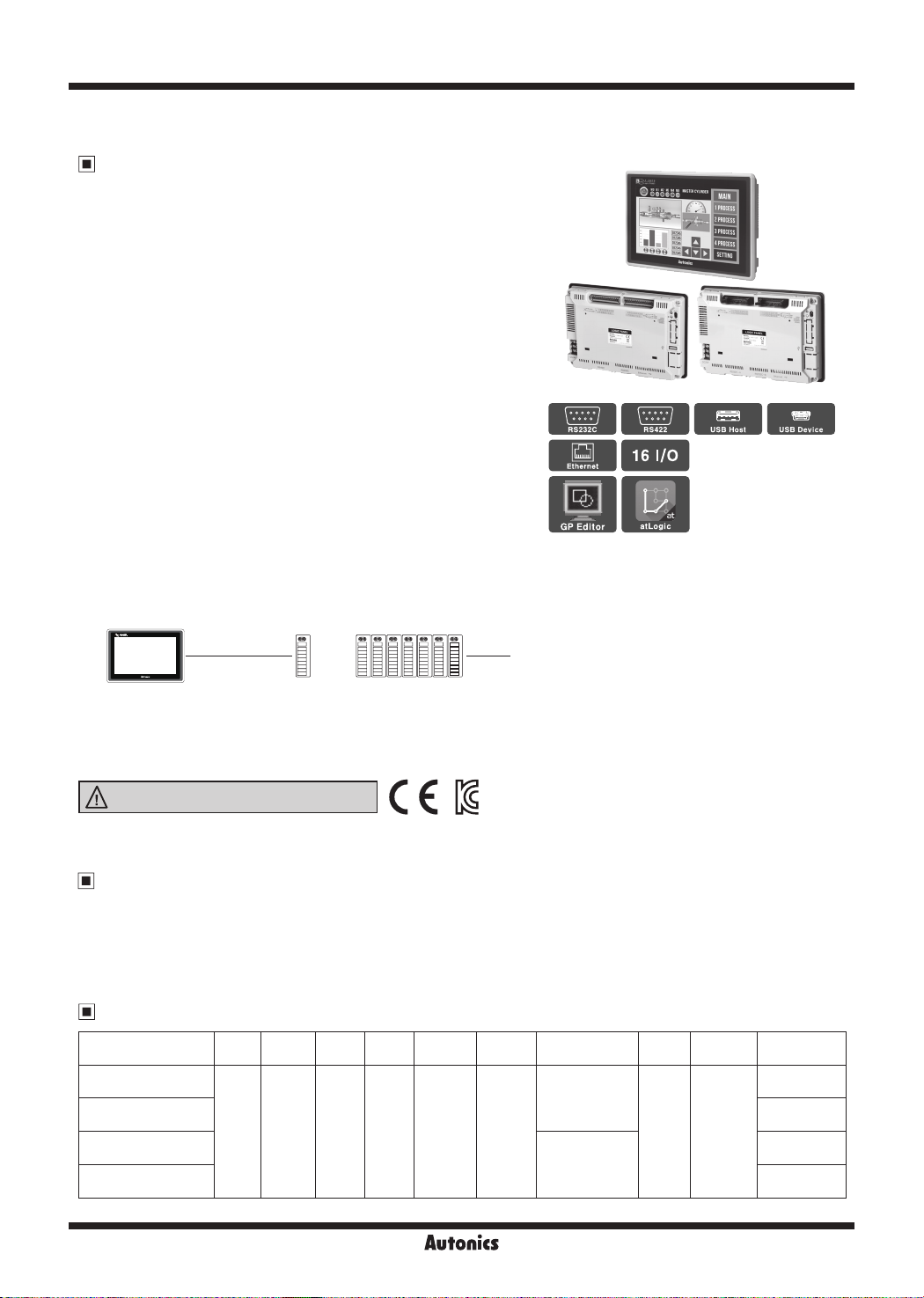
LP-S070 Series
Basic Type 7 inch Color LCD Logic Panel
Features
● Supports cost reducing, space saving, easy control
by PLC+HMI+I/O module integration
● Adopts 7 inch wide TFT LCD for realizing True Color
with 16,777,216 colors
● Analog touch method
: Free tag arrangement than matrix touch method
● Supports basic I/O of input 16-point, output 16-point
● Supports several device
(auxiliary device 10K Word, data device 10K Word, etc)
● Built-in large capacity memory
(program memory: 8,000 step, drawing memory: 16MB)
● Built-in position control function
: Provides simultaneous output for max. 100kHz pulse 2-point
● Easy software upgrade available on website
(1) LP rmware le (2) GP Editor (drawing program)
(3) atLogic (logic program) (4) Additional protocol
(5) Language and font, etc
● Data logger function
: Supports data gathering and backup of controller
● Supports variable image library
● Enables to monitor multi stations and multi channels at the same time
● Supports several interface
: Easy to connect various external devices with RS232C 2 ports and RS232C/RS422 multi communication ports
: Enables to extend additional external I/O (when connecting Autonics ARM Series, one communication cable
enables to extend 64-point per address, up to 31 address)
[Terminal block connector typoe] [Ribbon cable connector type]
.
§
RS232C RS422
~
Ethernet
§1
GP
Editor
-
.
§
16 1/0
~
atLogic
use
~
Host
use
'!!!I
Device
RS485
l
□
LP-S070 1 basic unit 7 expansion units
● Supports several fonts: Supports window true type and several bitmap font (selectable)
● Device monitoring function: Enables to monitor/control variable of connected control through communication
port
● Printer/Barcode reader connection: Enables to print out alarm history, to read barcode
Please read “Safety Considerations”
in the instruction manual before using.
Manual
00
● GP Editor user manual
It describes how to write screen data, and is about related usage of LP-S070 HMI function.
● atLogic user manual, atLogic programming manual, LP Series command manual
It contains install method and usage, commands, etc of atLogic.
● GP/LP user manual for communication: It describes connection for external devices such as PLC.
● LP-S070 user manual: It describes general information of the installation and usage of LP-S070 and system Contents.
Ordering Information
00
Model Item Series
LP-S070-T9D6-C5T
LP-S070-T9D6-C5R
LP-S070-T9D7-C5T
LP-S070-T9D7-C5R
f-------1
Logic
S series
panel
+
iDllii-
Monitor
Display
size
unit
TFT
7 inch
Color
LCD
Color
16,777,216
color
Max. 64-point (ARM 8 units × 8-point)
Power
supply
24VDCᜡ
Interface Module
RS232C, RS422,
USB HOST
USB DEVICE,
Ethernet
RS232C (2), USB
HOST
USB DEVICE,
Ethernet
All-inone
type
I/O
composition
IN:
16-point,
OUT:
16-point
I/O connector
Terminal block
connector
Ribbon cable
connector
Terminal block
connector
Ribbon cable
connector
V-58
Autonics
Basic Type 7 inch Color Logic Panel
SENSORS
CONTROLLERS
MOTION DEVICES
SOFTWARE
(J)
Temperature
Controllers
(K)
SSRs
(L)
Power
Controllers
(M)
Counters
(N)
Timers
(O)
Digital
Panel Meters
(P)
Indicators
(Q)
Converters
(R)
Digital
Display Units
(S)
Sensor
Controllers
(T)
Switching
Mode Power
Supplies
(U)
Recorders
(V)
HMIs
(W)
Panel PC
(X)
Field Network
Devices
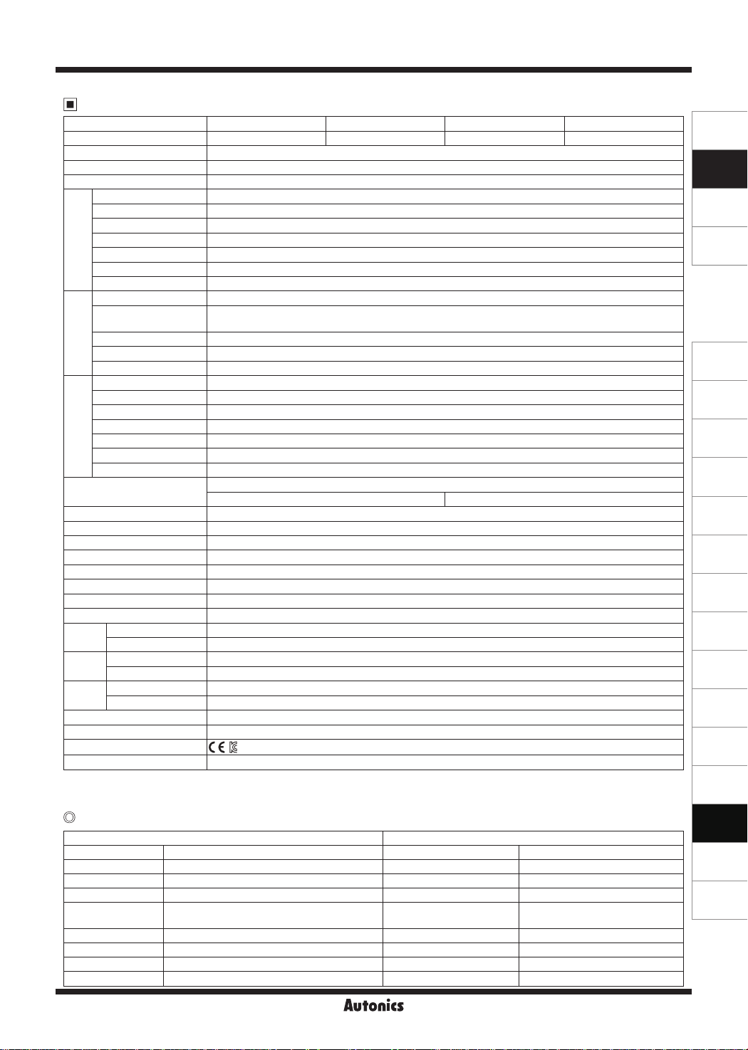
Specifications
Model LP-S070-T9D6-C5T LP-S070-T9D6-C5R LP-S070-T9D7-C5T LP-S070-T9D7-C5R
I/O connector type Terminal block connector Ribbon cable connector Terminal block connector Ribbon cable connector
I
I
Power supply 24VDCᜡ
Allowable voltage range 90 to 110% of power supply
Power consump ion Max. 7.2W
LCD type 7 inch TFT Color LCD
Resolution 800×480 dots
Display area 152.4×91.44mm
Color 16,777,216 color
LCD view angle Within each 60°/ 45°/ 60°/ 60° of top/bottom/left/right
performance
Backlight White LED
Graphic drawing
Brightness Adjustable by software
Language
Text
※1
English, Korean
• Vector font • 6×8, 8×8 ASCII character, high denition numbers
•
8×16 ASCII characters, 16×16 character by each country (1 to 8 imes bigger for wid h, 0 5 to 5 times bigger for height)
Graphic drawing memory 16MB
Number of user screen 500 pages
performance
Graphic drawing
Touch switch Analog touch
Command Basic command: 28, application command: 233
Program capacity 8K step
Processing time Average: approx. 2㎲/basic command, application command
I/O control type Batch processing
Control
Computer control mode Repeated-doubling method, interrupt processing
performance
Device range Refer to 'LP-S070 user manual'
Special function
Serial interface
※2
Positioning function
Asynchronous me hod: each port of RS232C, RS422
Each port of RS232C, RS422 Two ports of RS232C
USB interface Each of USB Host, USB Device (Version 1.1)
Ethernet interface IEEE802.3 (U), 10/100Base-T
Real-time controller RTC embedded
Battery life cycle Approx. 3 years at 25℃
Insulation resistance Over 100MΩ (at 500VDC megger)
Ground 3rd grounding (max. 100Ω)
Noise immunity ±0.5kV the squre wave noise (pulse width: 1㎲) by the noise simulator
Withstanding voltage 500VAC 50/60Hz for 1 min
Mechanical 0.75mm amplitude at frequency of 10 to 55Hz (for 1 min) in each X, Y, Z direction for 1 hour
Vibra
tion
Malfunction 0.5mm amplitude at frequency of 10 to 55Hz (for 1 min) in each X, Y, Z direction for 10 min
Mechanical 300m/s² (approx. 30G) in each X, Y, Z direction for 3 times
Shock
Malfunction 100m/s² (approx. 10G) in each X, Y, Z direction for 3 times
Ambient temperature 0 to 50℃, storage: -20 to 60℃
Environ
ment
Ambient humidity 35 to 85%RH, storage: 35 to 85%RH
Protec ion structure IP65 (front panel, IEC standard)
Accessory Fixing bracket: 4, battery (included)
Approval
※3
Weight
※
1: Supported language can be added. ※2: Please refer to 'LP-S070 user manual' for more special function.
※
3:The weight includes packaging. The weight in parenthesis is for unit only.
※
Environment resistance is rated at no freezing or condensation.
CE~
Approx. 699g (approx. 510g)
Input/Output Performance
Input performance Output performance
Input point 16-point Output point 16-point
Insulation method Photo coupler insulation Insulation method Photo coupler insulation
Voltage range 19.2 to 28.8VDCᜡ Voltage range 19.2 to 28.8VDCᜡ
Rated input voltage 24VDCᜡ Rated input voltage 24VDCᜡ
Input resistance
Input resistance Contact X0 to X5: 2.2㏀, Contact X6 to XF: 5.6㏀ Max. voltage falling when ON Max. 0.2VDCᜡ
Response time 1ms Response time 1ms
Common method 16-point/1COM Common method 16-point/1COM
Acceptable wire 0.3 to 0.7mm
Contact X0 to X5: approx. 10mA
Contact X6 to XF: approx. 4mA
2
Max. load current 0.1A/1point, 1.6A/1COM
Acceptable wire 0.3 to 0.7mm
I
I
I
I
I
2
Autonics
V-59

LP-S070 Series
Function
Figure display Line, rectangle, circle, text, bitmap
Numeral display Displays the designated device as numerical value. (decimal, hexadecimal, octal, binary, real number)
ASCII display Displays the designated device value as ASCII character.
Time display Displays current time or date.
Alarm history Registers alarm history.
Alarm list Displays generated (not backed up) alarm.
Comment display Displays the designated comment as device status or value.
Lamp Displays lamp as device status.
Part display Displays the designated parts as device status and value.
Tags
Line graph Displays several device values with a graph of broken line.
Trend graph Displays change of device value for time with a graph of broken line.
Bar graph Displays a device value with a bar graph.
Statistic graph Displays a ratio of several device values with pie graph.
Panel meter Displays a device value as panel meter.
Touch key Screen is switched, word/bit device values are set when it touched.
Numeral input Congures user input value in device.
ASCII input Congures user input ASCII code value in device.
System information function Monitors/Controls LP operation from PLC.
Recipe function Reads/Writes several PLC device collectively.
Security function Only acceptable user can observe/operate important data.
Barcode read func ion Connects barcode reader, read barcode.
Floating alarm function Warning message is oated when alarm is generated.
Time operation Specic bit device is ON/OFF for designated day and time.
Overlap window Available to form dynamically overlapping another base screen on the base one.
Dimensions
-------r-------
185
194
(unit: mm)
● Panel cut-out
Min. 240
+ 1.1
,._.____._.I·
EB
I • I /
186
0
+ 1.0
J
0
126
EB
Max. 4-R3
]
Min. 175
EB
Panel thickness
※
6.5 28.5
'
I
'
I
'
.
I
'
134
125
145.8
: max. 4mm
● Fixing bracket
15
M4 BOLT
V-60
Autonics

Basic Type 7 inch Color Logic Panel
SENSORS
CONTROLLERS
MOTION DEVICES
SOFTWARE
(J)
Temperature
Controllers
(K)
SSRs
(L)
Power
Controllers
(M)
Counters
(N)
Timers
(O)
Digital
Panel Meters
(P)
Indicators
(Q)
Converters
(R)
Digital
Display Units
(S)
Sensor
Controllers
(T)
Switching
Mode Power
Supplies
(U)
Recorders
(V)
HMIs
(W)
Panel PC
(X)
Field Network
Devices
Unit Description
Input
terminal
Output
terminal
Power
LED
Run/Stop
Switch
Program
status LED
USB
USB
Host
L
LCD Screen
Fixing bracket
_J
Power terminal
block
RS422
or
RS232C
-A
RS232C
or
RS232C
-B
Ethernet
Device
(2 slots is in upper side, 2 slot is in lower side)
Mounting slot
for bracket
● Ethernet port: For connecting LAN cable and hub, use direct cable, and for connecting PC directly, use cross cable.
● USB Device: When setting USB Device mode to HID mode in serial setting, it is for uploading/downloading GP Editor,
atLogic project. When setting to Storage mode, it is for transferring/coping data between PC and
LP-S070 with recognition as a storage device by PC.
For details, please refer to 'LP-S070 user manual'.
● USB Host: It is for transferring/coping data between USB storage device and LP-S070 and upgrading firmware.
● RS232C, RS422 port: For more information, refer to ' Serial Interface' of GP/LP Common Features.
Installation
1. Set LP-S070 in panel.
2. Set fixing brackets in 4 slots (2 slots is in upper side, 2 slots is in lower side).
Upper side
Mounting slot
for bracket
Lower side
3. Tighten fixing bracket with M4 screw driver and tightening torque is 0.3 to 0.5N.m.
M4 Screw driver
Autonics
V-61

LP-S070 Series
Input/Output Wiring
LP-S070-T9D6 (7)-C5R
● Input wiring (source type input module)
X0
X1
X2
X3
24VDC
X4
X5
X6
X7
COM1
COM3
LP-S070-T9D6 (7)-C5T
● Input wiring (source type input module)
24VDC
※
Check the pin number of the case before wiring.
X0
X1
X2
X3
X4
X5
X6
X7
X8
X9
XA
XB
XC
XD
XE
XF
COM1
COM2
X8
8
0
X9
9
1
XA
A
2
XB
B
3
XC
C
4
XD
D
5
XE
E
6
XF
F
7
COM2
+
+
COM4
+
+
0
1
2
3
4
5
6
7
8
9
A
B
C
D
E
F
+
+
● Output wiring (sink type output module)
Y0
L
Y1
L
Y2
L
Y3
L
Y4
L
Y5
L
Y6
L
Y7
L
24VDC
● Output wiring (sink type output module)
L
L
L
L
L
L
L
L
L
L
L
L
L
L
L
L
24VDC
Y0
Y1
Y2
Y3
Y4
Y5
Y6
Y7
Y8
Y9
YA
YB
YC
YD
YE
YF
Y8
L
8
0
Y9
L
9
1
YA
L
A
2
YB
L
B
3
YC
L
C
4
YD
L
D
5
YE
L
E
6
YF
L
F
7
+
+
-
-
0
1
2
3
4
5
6
7
8
9
A
B
C
D
E
F
+
-
Sold Separately
Connector socket
Please contact to the manufacturer of the socket and cable.
Socket HIF3BA-20D-2.54R Hirose Electric
Standard product Manufacturer
I/O terminal block and I/O cable
Suitable I/O terminal block INPUT/OUTPUT Suitable I/O cable
AFS-H20
(Interface terminal block)
ABS-H16PA (TN)-NN
(Relay terminal block)
AFE4-H20-16LF
(Sensor connector terminal block)
- -
※
It is only for ribbon cable connector (hirose connector) type.
※
" is cable length. (Basic specification 010: 1m, 020: 2m, the others are option)
"
□
※
For more information, refer to "I/O terminal block & cable catalog".
Communication cable (RS232C, RS422 port)
Serial connection cables which connect GP/LP with PLC or other external devices are sold separately.
Refer to "GP/LP Communication Cables".
V-62
INPUT
OUTPUT
OUTPUT
INPUT
OUTPUT
CH20-HP -4R
CH20-HP -C1T1R
CH20-HP -C1T5R
CH20-HP -C1T1R
CO20-HP -R (open type cable)
CO20-HP
□
□
□
□
□
-L (open type cable)
□
Autonics

Basic Type 7 inch Color Logic Panel
SENSORS
CONTROLLERS
MOTION DEVICES
SOFTWARE
(J)
Temperature
Controllers
(K)
SSRs
(L)
Power
Controllers
(M)
Counters
(N)
Timers
(O)
Digital
Panel Meters
(P)
Indicators
(Q)
Converters
(R)
Digital
Display Units
(S)
Sensor
Controllers
(T)
Switching
Mode Power
Supplies
(U)
Recorders
(V)
HMIs
(W)
Panel PC
(X)
Field Network
Devices
Serial Interface
● All devices are connectable with LP-S070 including PC, PLC, serial printer, barcode reader and dedicated connectors
can be connected with both RS232C and RS422 ports.
● Use the dedicated communication cable for the each connected device.
(Refer to the "GP/LP Communication Cables")
● For the method of wiring external devices like PLC, refer to "GP/LP communication manual".
Port NO. Pin
RS232C
5
•
•
4
• •
3
•
•
2
• •
1
•
D-Sub 9-pin
Male
RS422
5
0
0
4
0 0
3
0
0
2
0 0
1
0
D-Sub 9-pin
Female
Power Wiring
9
8
7
6
6
7
8
9
1 Not used
2 RXD
3 TXD
4 DTR
5 SG
6 DSR
7 Not used
8 Not used
9 Not used
1 TXD+
2 RXD+
3 Not used
4 Not used
5 SG
6 TXD7 RXD-
8 Not used
9 Not used
F.G.
-
+
● For power supply, use the wire of which cross section is at least 0.75mm² and
use the wire of which cross section is at least 1.25mm² for grounding.
● Use round terminal with at least 3mm of internal diameter and less than 6mm of
external diameter.
● Do not apply power before power line connection.
● Check power polarity.
● Tighten the terminal screw with 0.5 to 0.8N·m torque.
● Ground resistance should be less than 100Ω and ground it separately.
+
24VDC
-
Battery Replacement
Please contact out distributor to replace battery.
It may cause an explosion or a fire when improper battery is used.
Cautions during Use
1. Follow instructions in 'Cautions during Use'. Otherwise, it may cause unexpected accidents.
2. 24VDC power supply should be insulated and limited voltage/current or Class 2, SELV power supply device.
3. Install a power switch or circuit breaker in the easily accessible place for supplying or disconnecting the power.
4. Operate the product after supplying power to the product, input/output equipment, and load.
If operate product before supplying power, it may result in output error or malfunction.
5. Keep away from high voltage lines or power lines to prevent inductive noise.
Do not use near the equipment which generates strong magnetic force or high frequency noise.
6. Make a required space around the unit for radiation of heat, and do not block ventilation openings.
7. Do not push the touch panel with a hard and sharp object or push the panel with excessive force.
It may result in fire or malfunction.
8. When skin is smeared with liquid crystal from the broken LCD, rinse with running water for over 15 minutes.
If it gets into the eyes, rinse eyes with running water for over 15 minutes and contact a doctor.
9. This unit may be used in the following environments.
Indoors (in the environment condition rated in 'Specifications')
①
Altitude max. 2,000m
②
Pollution degree 2
③
Installation category II
④
Autonics
V-63
 Loading...