

DRW170936AB
Autonics
7 inch TFT Color LCD type Logic Panel
LP-S070
I N S T R U C T I O N M A N U A L
Please read the following safety considerations before use.
Safety Considerations
Please observe all safety considerations for safe and proper product operation to avoid
※
L_
hazards.
001
■
A -------71
symbol represents caution due to special circumstances in which hazards may occur.
※
Warning
Caution
1~
Warning
1. Fail-safe device must be installed when using the unit with machinery that may cause
serious injury or substantial economic loss. (e.g. nuclear power control, medical equipment,
ships, vehicles, railways, aircraft, combustion apparatus, safety
equipment, crime/disaster prevention devices, etc.)
Failure to follow this instruction may result in re, personal injury, or economic loss.
2. Use the unit within the rated specications.
Failure to follow this instruction may result in shortening the life cycle of the product or re.
3. Do not connect, repair, or inspect the unit while connected to a power source.
Failure to follow this instruction may result in re.
4. Check 'Power Wiring', 'Serial Interface', and 'Input/Output Wiring' before wiring.
Failure to follow this instruction may result in re.
5. In preparation for product damage, communication error, or malfunction, install external
emergency stop circuit, forward/reverse interlock circuit, limit switch, emergency stop
switch, or other protection circuit.
Failure to follow this instruction may result in re, personal injury, or economic loss.
6. Since Lithium battery is embedded in the product, do not disassemble or burn the unit.
Failure to follow this instruction may result in re.
7. Do not disassemble or modify the unit.
Failure to follow this instruction may result in re.
8. Please contact to us for battery replacement.
Caution
1. Do not use the unit in the place where ammable/explosive/corrosive gas, humidity,
direct sunlight, radiant heat, vibration, impact, or salinity may be present.
Failure to follow this instruction may result in re or explosion.
2. Use dry cloth to clean the unit, and do not use water or organic solvent.
Failure to follow this instruction may result in electric shock or re.
3. When connecting the power input, use AWG 23 cable or over and tighten the
terminal screw with a tightening torque of 0.5 to 0.8N.m.
Failure to follow this instruction may result in re or malfunction due to contact failure.
4. Keep metal chip, dust, and wire residue from owing into the unit.
Failure to follow this instruction may result in re or product damage.
5. Do not push over 2 point at the same time.
Failure to follow this instruction may result in malfunction.
Ordering Information
LP
S T 9 D 6 C 5 R
Item
The above specications are subject to change and some models may be discontinued without
※
notice.
Be sure to follow cautions written in the instruction manual, user manual and the technical
※
descriptions (catalog, homepage).
Thank you for choosing our Autonics product.
______
Failure to follow these instructions may result in serious injury or death.
Failure to follow these instructions may result in personal injury or product damage.
070
Series
Screen size
Color
Display unit
-
ll
Interface
Power supply
I/O connector
I/O composition
Module
L__
R Ribbon cable connector
T Terminal block connector
5 IN: 16 point, OUT: 16 point
C All-in-one type
~~~~~
RS232C, RS422,USB HOST
6
USB DEVICE, Ethernet
RS232C(2),USB HOST
7
USB DEVICE, Ethernet
D 24VDC
9 16,777,216 color
T TFT Color LCD
070 7 inch
S S series
LP Logic Panel
I
Specications
00
General specications
◎
Model LP-S070-T9D6-C5R(T) LP-S070-T9D7-C5R(T)
Power supply 24VDC
Allowable voltage
range
Power consumption Max. 7 2W
Serial interface
USB interface Each of USB Host, USB Device (version 1.1)
Ethernet interface EEE802.3(U), 10/100Base-T
Real-time controller RTC embedded
Battery life cycle 3 years at 25
Insulated resistance Over 100MΩ (at 500VDC megger)
Ground 3rd grounding (max. 100Ω)
Noise immunity ±0.5kV the squre wave noise (pulse width: 1㎲) by the noise simulator
Withstanding voltage 500VAC 50/60Hz for 1 minute
Mechanical
Vibration
Malfunction
Mechnical 300m/s² (approx. 30G) in each X,Y,Z direction for 3 times
Shock
Malfunction 100m/s² (approx. 10G) in each X,Y,Z direction for 3 times
Ambient
temperature
Environ
ment
Ambient
humidity
Protection structure P65 (front panel, IEC standard)
Accessory Fixing bracket: 4pcs, battery (included)
Approval
t=~==E~===========~L-------7
※1
Weight
※
1: The weight includes packaging. The weight in parenthesis is for unit only.
~~~±(
※
Environment resistance is rated at no freezing or condensation.
Performance specications
◎
Display performance
.
LCD type TFT Color LCD
Resolution 800×480 dot
Display area 152.4mm×91.44mm
Color 16,777,216 color
LCD view angle Within each 60°/45°/60°/60°of top/bottom/left/right
Backlight White LED
Brightness Adjustable by software
Graphic drawing performance
Language
Text
Graphic drawing memory
Number of user screen
Touch switch Analog touch
Interface type
Communnication
interface
Input Output
Input point 16 point Out point 16 point
Insulation method Photo coupler insulation Power supply 24VDC
Rated input voltage 24VDC Insulation method
Input resistance
I
Voltage range 19.2-28.8VDC
Input resistance
Response time 1ms
Common method 16 point/1 COM Common method 16 point/1 COM
Acceptable wire 0.3 to 0.7mm
Control performance
Command Basic command: 28, application command: 233
Program capacity 8K step
Processing time Average: approx. 2㎲/basic command, application command
I/O control type
Computer control mode
Device range Refer to 'LP-S070 user manual'
Special function Positioning function
※
※
● For power supply, use the wire of which cross section is at least 0.75mm² and use the
● Use round terminal with at least 3mm of internal diameter and less than 6mm of
●Do not apply power before power line connection.
●Check power polarity.
●Tighten the terminal screw with 0 5 to 0.8N
Loo
●Ground resistance should be less than 100Ω and ground it separately.
1
※
1: Supported language can be added.
2: Please refer to 'LP-S070 user manual' for more special function.
Power Wiring
wire of which cross section is at least 1.25mm² for grounding.
external diameter.
------11'_11;71111
90 to 110% of power supply
asynchronous method: each port of RS232C, RS422
Each port of RS232C, RS422 Two ports of RS232C
℃
0.75mm amplitude at frequency of 10 to 55Hz (for 1 min) in each X, Y, Z direction for 1 hour
0.5mm amplitude at frequency of 10 to 55Hz (for 1 min) in each X, Y, Z direction for 10 min
0 to 50℃, storage: -20 to 60
35 to 85% RH, storage: 35 to 85%RH
Approx. 699g (approx. 510g)
~
(
~===========
Korean, English
•Vector font •6×8, 8×8 ASC II character, high quality view of number
•8×16 ASCII character, 16×16 regional characters
(1 to 8times bigger for width, 0.5 to 5 times for height)
16MB
500 pages
LP-S070-T9D6-C5R(T): each port of RS232C, RS422, USB Host, USB Device, Ethernet
I
LP-S070-T9D7-C5R(T): two ports of RS232C, USB Host, USB Device, Ethernet
I
Contact X0 to X5: approx. 10mA
Contact X6 to XF: approx. 4mA
Contact X0 to X5: 2 2
Contact X6 to XF: 5.6
2
Batch processing
Repeated-doubling method, interrupt processing
㏀
㏀
2
※
m torque.
℃
Photocoupler insulation
Rated load voltage 24VDC
Allowable load voltage range
Max. load current
Max. voltage falling when ON
Acceptable wire 0 3 to 0.7mm
19.2-28 8VDC
0.1A/1 point,
1 6A/1COM
Max. 0.2VDC
2
+
24VDC
--+
Serial Interface
● All devices connectable into LP-S070 including PC, PLC, serial printer, barcode reader, and dedicated
connectors can be connected in to both RS232C and RS422 ports.
●Device must be set for the port in system setting for LP-S070. For details, please refer to 'LP-S070 user manual'.
●For connecting external device such as PLC, refer to 'GP, LP user manual for communication'.
Port Pin Port Pin
RS232C
RS232C-A
RS232C-B
5
•
4
•
3
•
2
•
1
•
D-Sub 9-pin Male
•
•
•
•
1 Non-Used RS422 1 TXD+
2 RXD 2 RXD+
3 TXD 3 Non-Used
9
4 DTR 4 Non-Used
5 SG 5 SG
8
6 DSR 6 TXD-
7
7 Non-Used 7 RXD-
6
8 Non-Used 8 Non-Used
9 Non-Used 9 Non-Used
0
1
2
3
4
5
D-Sub 9-pin Female
6
0
0
7
0
0
8
0
0
9
0
0
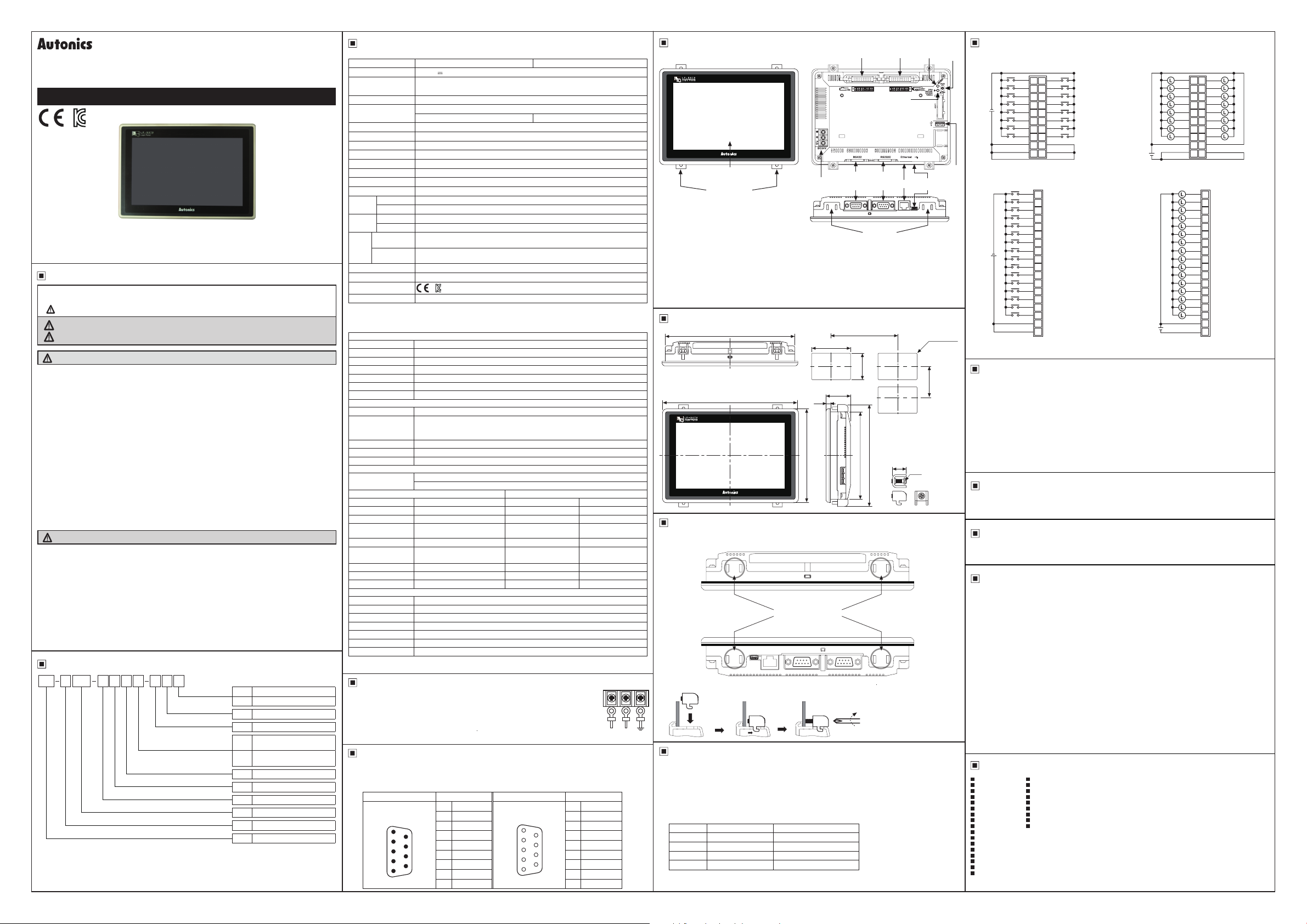
Unit Description Input/Output Wiring
LCD Screen
(2 slots is in upper side, 2 slot is in lower side)
●Ethernet port: For connecting LAN cable and hub, use direct cable, and for connecting PC directly, use cross
●USB Device: When setting USB Device mode to HID mode in serial setting, it is for uploading/downloading
●USB Host:
Fixing bracket
cable.
GP Editor, SmartStudio project. When setting to Storage mode, it is for transferring/coping data
between PC and LP-S070 with recognition as a storage device by PC.
For details, please refer to 'LP-S070 user manual'.
It is for transferring/coping data between USB storage device and LP-S070 and upgrading
firmware.
Power terminal
block
Input
terminal
RS422
or
RS232C-A
Program
status LED
RS232C
or
RS232C-B
Mounting slot
for bracket
terminal
Dimensions
I
C
I
185
194
I
L----
1
186
6.5
134
Min. 240
1.1
0
1.0
0
126
35
Panel thickness: max.
※
Fixing bracket
125
145 8
Output
Ethernet
15
M4
Power
LED
USB
Device
(unit: mm)
Max. 4-R3
Min. 175
Run/Stop
1. LP-S070-T9D6(7)-C5R
Switch
●Input wiring (source type)
X0
8
0
X1
9
1
X2
A
2
X3
B
3
X4
C
COM1
COM3
COM1
COM2
4
X5
D
5
X6
E
6
X7
F
7
+
+
+
+
X0
0
X1
1
X2
2
X3
3
X4
4
X5
5
X6
6
X7
7
X8
8
X9
9
XA
A
XB
B
XC
C
XD
D
XE
E
XF
F
+
+
24VDC
USB
2. LP-S070-T9D6(7)-C5T
Host
●Input wiring (source type)
24VDC
※Check the pin number of the case before wiring.
Manual
For the detail information and instructions, please refer to user manual and user manual for communication,
and be sure to follow cautions written in the technical descriptions (catalog, homepage).
● GP Editor user manual
It describes how to write screen data, and is about related usage of LP HMI function.
4mm
● SmartStudio user manual, SmartStudio programming manual, LP series command manual
It contains install method and usage, commands, etc of SmartStudio.
● GP, LP user manual for communication
It describes connection for external devices such as PLC.
● LP-S070 user manual
It describes general information on the installation and usage of LP-S070 and system contents.
Cable (sold separately)
00
Communication cables connectable into external devices such as PLC are sold separately.
Please refer to "GP, LP user manual for communication" for communication cable.
Installation
1. Set LP-S070 in panel.
2. Set xing brackets in 4 slots (2 slots is in upper side, 2 slots is in lower side).
Upper side
(~
Lower side
'
3. Tighten xing bracket with M4 screw driver and tightening torque is 0 3 to 0.5N
LJ~~-~==-j~
Software
00
● GP Editor
GP Editor is for editing shape, arrangement, default of tag data which is displayed on LP-S070
screen.
● SmartStudio
SmartStudio is for writing program and debugging to LP-S070.
For GP Editor, SmartStudio software, computer specification is as below.
※
Operating system: Windows XP/7/8/10 (SmartStudio does not support Window XP.)
Item Minimum specication Recommended specication
CPU Pentium4 or above Pentium Dual Core
Memory 512MB 1GB
Hard disk 1GB (available space) 5GB (available space)
Resolution 1024
I
● Firmware
Please refer to 'LP-S070 user manual', 'GP Editor user manual', and 'SmartStudio user manual'.
fu&ir•~~~
https://manualmachine.com/
~
~t~
768 1280×1024
×
I I
~
Mounting slot
for bracket
n
~~
~·==~-~~j\
~-·~--1-
9 ~
-
m.
M4 Screw driver
I
Battery Replacement
Please contact our service center to replace LP-S070 battery.
t may cause an explosion or a re when using improper battery.
Cautions during Use
00
1. Follow instructions in 'Cautions during Use'. Otherwise, it may cause unexpected accidents.
2. 24VDC power supply should be insulated and limited voltage/current or Class 2, SELV power supply
device.
3. Install a power switch or circuit breaker in the easily accessible place for supplying or disconnecting
the power.
4. Operate the product after supplying power to the product, input/output equipment, and load.
If operate product before supplying power, it may result in output error or malfunction.
5. Keep away from high voltage lines or power lines to prevent inductive noise.
Do not use near the equipment which generates strong magnetic force or high frequency noise.
6. Make a required space around the unit for radiation of heat, and do not block ventilation openings.
7. Do not push the touch panel with a hard and sharp object or push the panel with excessive force.
It may result in fire or malfunction.
When skin is smeared with liquid crystal from the broken LCD, rinse with running water for over 15
minutes.
If it gets into the eyes, rinse eyes with running water for over 15 minutes and contact a doctor.
8. This unit may be used in the following environments.
Indoors (in the environment condition rated in 'Specifications')
①
Altitude max. 2,000m
②
Pollution degree 2
③
------~
Installation category II
④
Major Products
00
Photoelectric Sensors Temperature Controllers
■ ■
Fiber Optic Sensors Temperature/Humidity Transducers
■ ■
Door Sensors SSRs/Power Controllers
■ ■
Door Side Sensors Counters
■ ■
Area Sensors Timers
■ ■
Proximity Sensors Panel Meters
■ ■
Pressure Sensors Tachometer/Pulse (Rate)Meters
■ ■
Rotary Encoders Display Units
■ ■
Connector/Sockets Sensor Controllers
Switching Mode Power Supplies
■
Control Switches/Lamps/Buzzers
■
I/O Terminal Blocks & Cables
■
Stepper Motors/Drivers/Motion Controllers
■
Graphic/Logic Panels
■
Field Network Devices
■
Laser Marking System (Fiber, Co₂, Nd:yag)
■
Laser Welding/Cutting System
■
■ ■
X8
X9
XA
XB
XC
XD
XE
XF
COM2
COM4
●Output wiring (sync type)
●Output wiring (sync type)
24VDC
24VDC
Y0
Y8
8
0
Y1
Y9
9
1
Y2
YA
A
2
Y3
YB
B
3
Y4
YC
C
4
Y5
YD
D
5
Y6
YE
E
6
Y7
YF
F
7
+
+
-
-
Y0
0
Y1
1
Y2
2
Y3
3
Y4
4
Y5
5
Y6
6
Y7
7
Y8
8
Y9
9
YA
A
YB
B
XC
C
XD
D
YE
E
YF
F
+
-
DRW170936AB
 Loading...