

Page 1
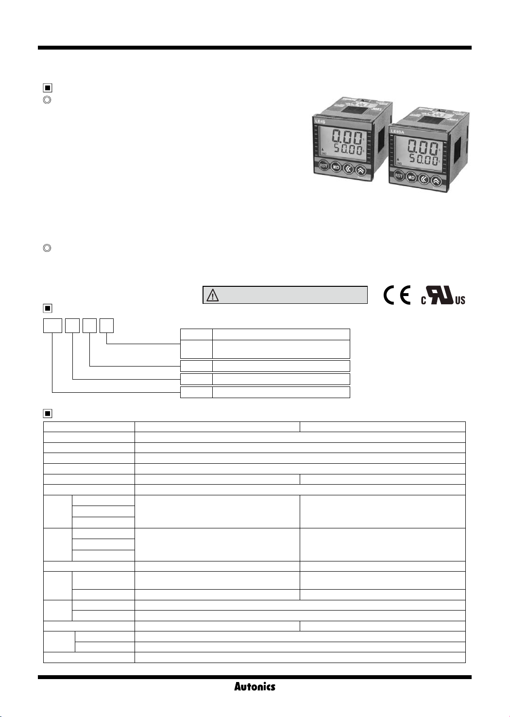
LE4S Series
DIN W48×H48mm Digital backlight LCD timer
Features
Upgraded Features
● Mounting space saving with compact design
: downsized by approx. 22% in depth compared to existing models
(length of panel on the back side is 56mm)
● Available to set each value and time range separately when
choosing Flicker(FK, FK I) or ON-OFF Delay(ON OFF D,
ON OFF D I) output mode
● Adds Flicker 1 mode(LE4SA)
● Settable One-shot output time(0.01 to 99.99sec.)
(existing model: xed 0.5 sec.)
● Congurable time range (added 9.999sec.): Settable by 0.001sec. unit
● Selectable min. input time: 1ms or 20ms (LE4S)
● Improved return time: 100ms
● Backlight ON/OFF function
Original Features
● Wide time range(0.01sec. to 9999hour)
● Lock setting function for saving setting data
● Soft touch setting
● High visibility display with backlight
Ordering information
LE 4 S
Output
Size
Digit
Item
No mark Time-limit contact 1c
A
S DIN W48×H48
4 9999(4digit)
LE LCD Timer
※
Sockets (PG-08, PS-08, PS-M08) are sold separately.
Specications
Model LE4S LE4SA
Function Multi time and Multi operation
Display method LCD display(Backlight)
Power supply 24-240VAC 50/60Hz, 24-240VDC universal
Allowable voltage range 90 to 110% of rated voltage
Power consumption 24-240VAC: Max. 4.5VA, 24-240VDC: Max. 2W 24-240VAC: Max. 4VA, 24-240VDC: Max. 1.6W
Return time Max. 100ms
START
Min.
INHIBIT
input
signal
RESET
START
INHIBIT
Input
RESET
Timing operation Signal ON Start Power ON Start
Contact type Time limit SPDT(1c)
Control
output
Contact capacity 250VAC 5A resistive load 250VAC 3A resistive load
Mechanical Min. 10,000,000 operations
Relay
life cycle
Electrical Min. 100,000 operations (at rated contact capacity)
Output mode 10 operation modes 8 operation modes
Environ
-ment
Accessory Bracket
※
Ambient temperature -10 to 55℃, storage: -25 to 65
Ambient humidity 35 to 85%RH
Environment resistance is rated at no freezing or condensation.
1ms, 20ms(selectable)
• No-voltage input
Impedance at short-circuit : Max. 1㏀,
Residual voltage : Max. 0.5V,
Impedance at open-circuit : Min. 100
Please read “Caution for your safety” in operation
manual before using.
Time-limit contact 2c,Time-limit contact
1c+Instantaneous contact 1c(selectable)
mm
-
-
㏀
Selectable Time limit DPDT(2c), Time limit SPDT(1c)+
Instantaneous SPDT(1c) (depends on operation mode)
℃
K-20
Page 2
LCD Timer(Touch Type)
Specications
Model LE4S LE4SA
Repeat error
Setting error
Voltage error
Max. ±0.01% ±0.05sec.(Power ON Start)
Max. ±0.005% ±0.03sec.(Signal ON Start)
Max. ±0.01% ±0.05sec.
Temperature error
Insulation resistance 100MΩ(at 500VDC megger)
Dielectric strength 2000VAC 50/60Hz for 1 minute
Noise strength ±2kV the square wave noise(pulse width: 1㎲) by the noise simulator
Vibration
Shock
Mechanical 0.75mm amplitude at frequency of 10 to 55Hz(for 1 min.) in each of X, Y, Z directions for 1hour
Malfunction 0.5mm amplitude at frequency of 10 to 55Hz(for 1 min.) in each of X, Y, Z directions for 10 minutes
Mechanical 300m/s² (approx. 30G) in each of X, Y, Z directions for 3 times
Malfunction 100m/s² (approx. 10G) in each of X, Y, Z directions for 3 times
Approval
Unit weight Approx. 98g
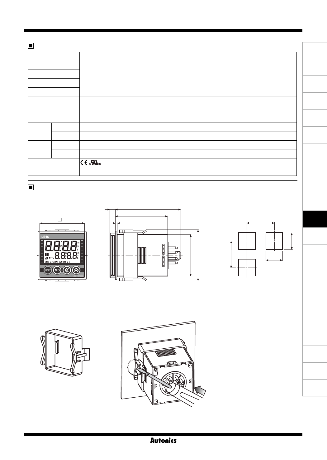
Dimensions
6 70
56
48
2
● Panel cut-out
Min. 65
(A)
Photo
electric
sensor
(B)
Fiber
optic
sensor
(C)
Door/Area
sensor
(D)
Proximity
sensor
(E)
Pressure
sensor
(F)
Rotary
encoder
(G)
Connector/
Socket
(H)
Temp.
controller
(I)
SSR/
Power
controller
(J)
Counter
(K)
Timer
● Bracket and mounting
44.8
(L)
Panel
meter
+0.6
0
45
(M)
Tacho/
56
Min. 65
※
Insert product into a panel, fasten
bracket by pushing with
+0.6
45
0
tools as
shown above.
Speed/ Pulse
meter
(N)
Display
unit
(O)
Sensor
controller
(P)
Switching
mode power
supply
(Q)
Stepper
motor&
Driver&Controller
(R)
Graphic/
Logic
panel
(S)
Field
network
device
(T)
Software
(U)
Other
K-21
Page 3
LE4S Series
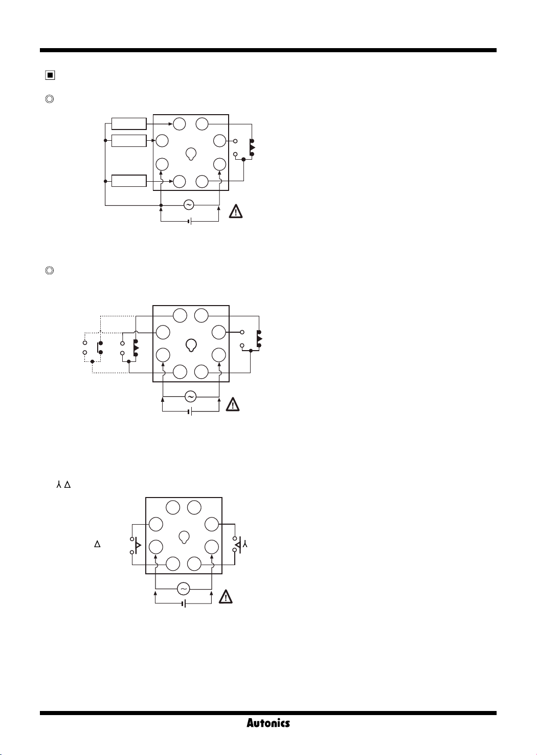
Connections
LE4S
3
2
4
1
-
+
SOURCE
6
7
8
CONTACT OUT:
250VAC 5A RESISTIVE LOAD
(Time limit contact 1c)
24-240VAC 50/60
24-240VDC
Hz
RESET
START
INHIBIT
LE4SA
● [ON.D] [ON.D.II] [FK] [FKI] [INT] [T] [T.I] mode
4 5
+
6
7
8
CONTACT OUT:
250VAC 3A RESISTIVE LOAD
(Time limit contact 1c)
24-240VAC 50/60
24-240VDC
Hz
3
2
(Instantaneous
contact 1c)
※
Time limit contact 1c + Instantaneous contact 1c or Time limit contact 2c (Selectable)
(Time limit
contact1c)
1
-
SOURCE
([T] [T.I] : Time limit 2c only.)
- ] mode
● [
(Time limit contact 1a)
K-22
455
3
Contact Contact
2
1
-
SOURCE
+
6
7
8
(Time limit contact 1a)
24-240VAC 50/60
24-240VDC
CONTACT OUT:
250VAC 3A RESISTIVE LOAD
Hz
Page 4
LCD Timer(Touch Type)
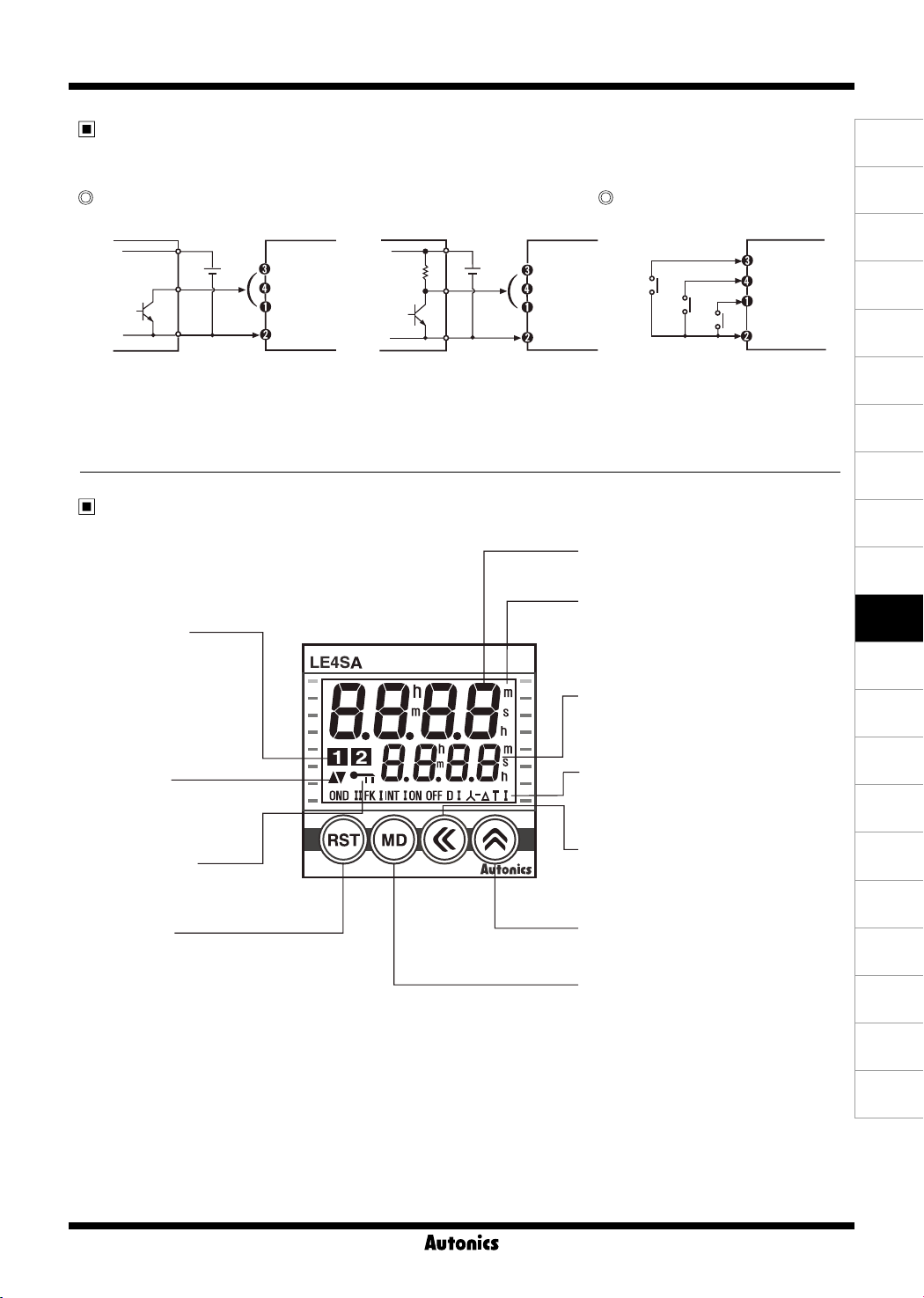
Input connections
LE4S is No-voltage input(Short-circuit and open) type.
Solid-state input Contact input
Sensor Sensor
12-24VDC 12-24VDC
+
-
Q1
● Q1 is ON : Operating
● Sensor : NPN open collector output
※
Be sure that it is not insulated between power and input terminal block.
LE4S LE4S LE4S
START
RESET
INHIBIT
Input 0V
RL
Q2
● Q2 is ON : Operating
● Sensor : NPN universal output
+
-
START
RESET
INHIBIT
S1
S2
Input 0V
● S1, S2, S3 are ON : Operating
● Please use reliable contact
enough to ow 5VDC 1mA.
Parts description
● Time progressing display
It displays the current time.
● Time unit
It displays the time unit.
● Output display
It displays the status
of output contact.
● UP/DOWN
It displays time progressing
UP(▲), DOWN(▼).
● Key lock display
It displays the status
of key lock.
● RESET key
Used for initializing time progressing
and output return.
(h:hour)(m:min.)(s:sec.)
※
When the time is progressing, it
is ashing at a rate of (0.5sec.)
● Time setting display
It displays the setting time.
● Operation mode
It displays the current operation mode.
(ex: OND=ON Delay)
● SHIFT key
Used for advancing to setting time change
mode and moving to each digit.
● UP key
Used for advancing to function setting
mode, setting time change checking.
● MODE key
Used for changing the set value.
S3
START
RESET
INHIBIT
Input 0V
(A)
Photo
electric
sensor
(B)
Fiber
optic
sensor
(C)
Door/Area
sensor
(D)
Proximity
sensor
(E)
Pressure
sensor
(F)
Rotary
encoder
(G)
Connector/
Socket
(H)
Temp.
controller
(I)
SSR/
Power
controller
(J)
Counter
(K)
Timer
(L)
Panel
meter
(M)
Tacho/
Speed/ Pulse
meter
(N)
Display
unit
(O)
Sensor
controller
(P)
Switching
mode power
supply
(Q)
Stepper
motor&
Driver&Controller
(R)
Graphic/
Logic
panel
(S)
Field
network
device
K-23
(T)
Software
(U)
Other
Page 5
LE4S Series
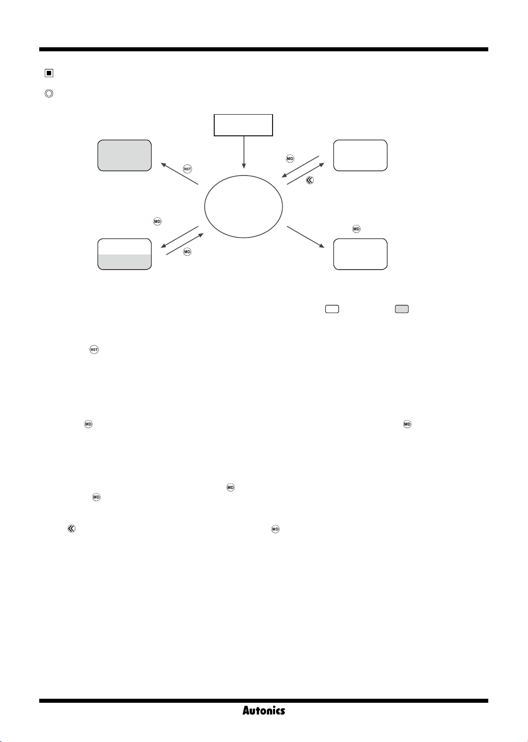
Function and time setting
Configuration
Power On
key
※
Setting time
change mode
key
Checking out-
put
contact status
LE4SA only.
Reset
key
for 3sec.
Function
setting mode
※
If changing function setting,
key
key
RUN mode
while pressing
key
for 3sec.
operation will stop.
: Enabled mode : Disabled mode
● Reset
Reset using key in Run mode
● Run mode
The operation status(When power is on for the rst time : factory default setting) is displayed.
It could enter into function setting mode, setting value change mode and output contact status mode.
● Function setting mode
If pressing key over 3 sec. in the Run mode, it will enter into function setting mode and if pressing key over 3 sec.
in function setting mode, it will return to Run mode.
※
Even if it enter into function setting mode in Run mode, time progressing and output control will continue.
※
If operation settings are changed in function setting mode, all outputs will be off and reset on returning to run mode.
● Output contact status mode(LE4SA only)
Output contact status are displayed while pressing key in Run mode.
※
If pressing
key over 3 sec., it will enter into function setting mode.
● Setting time change mode
Press key to enter into setting time change mode and press key to return to Run mode.
Even if signal is input when changing setting time, time progressing and output control will be continue.
If no key is pressed over 60 sec. in setting time change mode, it will return to Run mode.
※
If no key is pressed over 60 sec. in setting time change mode, it will return to Run mode and previous parameter
value is not stored.
K-24
Page 6
LCD Timer(Touch Type)
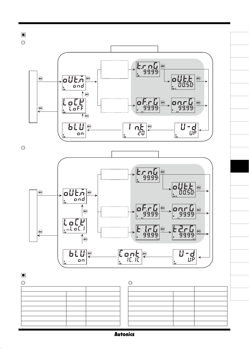
Function setting mode
LE4S
[
OND
[
ONd2
[
INt1
mode
key key
[
FLK
[
NFD
mode
key
key 3sec.
RUN mode
key 3sec.
1)Output operation
mode
7)Key lock
6)Backlight On/Off
key
key
LE4SA
[
OND
[
INT
1)Output operation
mode
key 3sec.
7)Key lock
RUN mode
key 3sec.
6)Backlight On/Off
key
key
key
key
[
FLK
mode
[
S-D
[
TWm1
Factory default
LE4S
Parameter Factory default
Output operation mode
Time range
Time Up/Down
Min. input signal
Backlight On/Off
Key lock
Setting time
OUtM OND
tRNG 9(99
U-D UP
InT 20
BLU ON
LOCK lOFF
-
5)00
Function setting mode
], [
],
ONd1
], [
],
INT
], [
]
OFD
], [
],
FLk1
], [
]
NFd1
5)Min. input signal
Function setting mode
], [
],
ONd2
mode
]
], [
]
FLk1
], [
],
TWN
mode
]
5)Min. input signal
LE4SA
Parameter Factory default
Output operation mode
Time range
Time Up/Down
Output contact
Backlight On/Off
Key lock
Setting time
2)Time range
Time range
tOFF
2)Time range
Time range
tOFF
Time range
T1
key
key
key
3)One-Shot output time
※
ONd2
mode
tON
key
key
3)One-Shot output time
※
ONd2
mode
key
key
Time range
key
4)Time Up/Down
key
Time range
tON
key
Time range
T2
key
4)Time Up/Down
OUtM OND
tRNG 9(99
U-D UP
CONT 1c1C
BLU ON
LOCK LOc1
-
5)00
(A)
Photo
electric
sensor
(B)
Fiber
optic
sensor
(C)
Door/Area
sensor
(D)
Proximity
sensor
(E)
Pressure
sensor
(F)
Rotary
encoder
(G)
Connector/
Socket
(H)
Temp.
controller
(I)
SSR/
Power
controller
(J)
Counter
(K)
Timer
(L)
Panel
meter
(M)
Tacho/
Speed/ Pulse
meter
(N)
Display
unit
(O)
Sensor
controller
(P)
Switching
mode power
supply
(Q)
Stepper
motor&
Driver&Controller
(R)
Graphic/
Logic
panel
(S)
Field
network
device
(T)
Software
(U)
Other
K-25
Page 7
LE4S Series
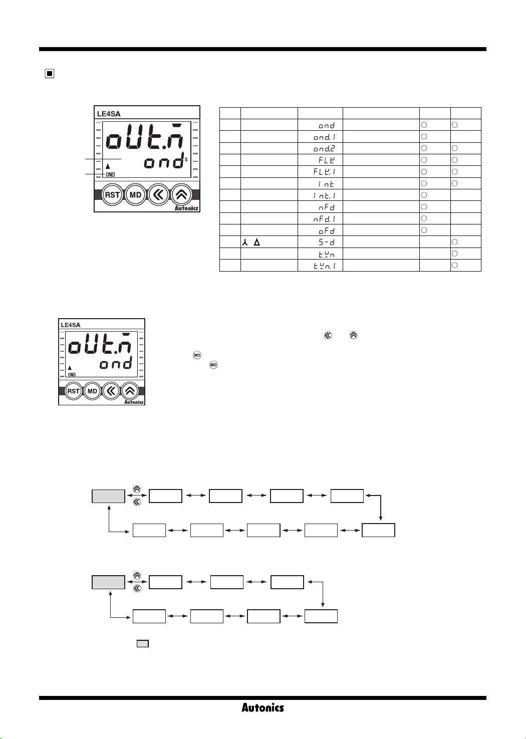
Output operation mode
● LE4S/LE4SA output operation mode
※
Display 2
※
Display 1
● Output operation mode
NO※Display 1
1 OND ON Delay
2 OND
3 OND
4 FK Flicker
5 FK
6 INT Interval
7 INT
8 ON OFF D ON-OFF Delay
9 ON OFF D
10 OFF D OFF Delay
11 - STAR-Delay
12 T Twin
13 T
Ⅰ
Ⅱ
Ⅰ
Ⅰ
Ⅰ
※
Display 2 Operation mode LE4S LE4SA
ON Delay 1
ON Delay 2
Flicker 1
Interval 1
Ⅰ
ON-OFF Delay 1
Twin 1
-
-
-
-
-
-
-
-
1) In function setting mode, it enter into output operation mode as shown in the [Fig. 1].
2) Select proper output operation mode using
and key.
(Refer to Output operation owchart)
3) Press
4) If pressing
key to set output operation mode and move to next mode.
key for 3 sec. in any function setting mode, it will return to Run mode.
[Fig.1]
※
Output operation owchart
< LE4S >
OND ONd1 ONd2 FLK FLk1
< LE4SA >
OND
※
The shaded parameter(
ONd2 FLK FLk1
TWn1
) is factory default.
INTINt1NFDNFd1OFD
INTS-DTWN
K-26
Page 8
LCD Timer(Touch Type)
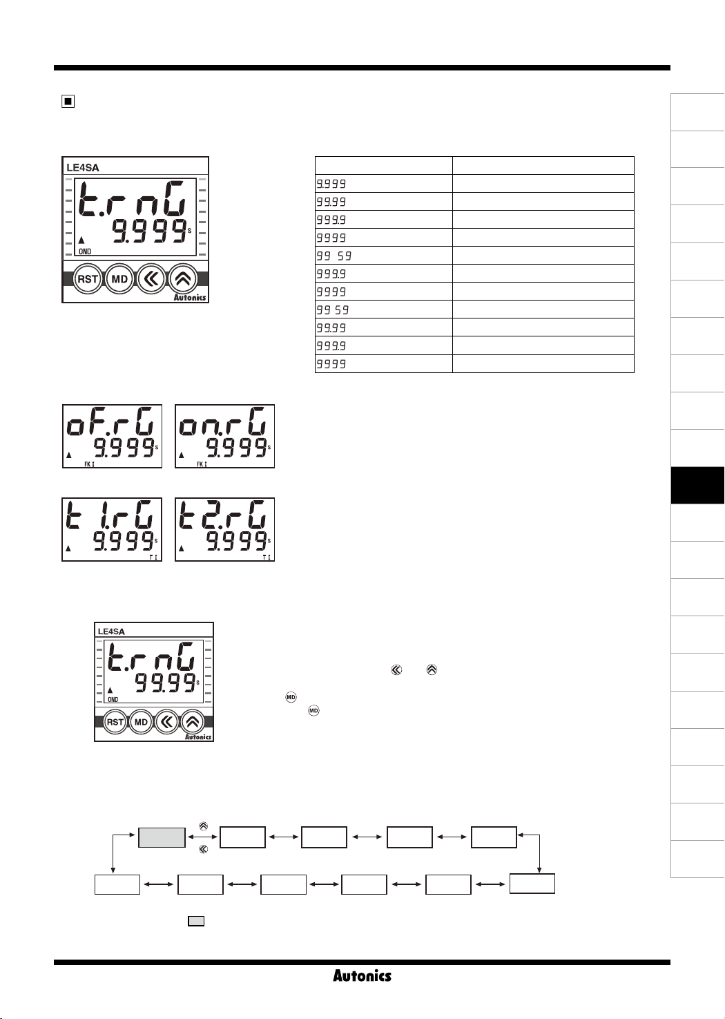
Time Range
● Time range specications
time range
tOFF
time range
T1
● Time range selection method
tON
time range
T2
time range
Parameter Time range specication
s (9.999s) 0.010sec. to 9.999sec.
s (99.99s) 0.01sec. to 99.99sec.
s (999.9s) 0.1sec. to 999.9sec.
s (9999s) 1sec. to 9999sec.
m s (99m59s) 0m01sec. to 99min. 59sec.
m (999.9m) 0.1min. to 999.9min.
m (9999m) 1min. to 9999min.
h m (99h59m) 0h01min. to 99hour 59min.
h (99.99h) 0.01hour to 99.99hour
h (999.9h) 0.1hour to 999.9hour
h (9999h) 1hour to 9999hour
※
Time range according to output operation mode
-Time range[
:
OND, ONd1, ONd2, INT, INt1, OFD
-
tOFF/tON
:
FLK, FLk1, NFD, NFd1
- T1/
:
time range[
T2
S-D, TWN, TWn1
]
tRNG
time range[
T!RG/T@RG
mode
OfRG/OnRG
mode
]
mode
]
(A)
Photo
electric
sensor
(B)
Fiber
optic
sensor
(C)
Door/Area
sensor
(D)
Proximity
sensor
(E)
Pressure
sensor
(F)
Rotary
encoder
(G)
Connector/
Socket
(H)
Temp.
controller
(I)
SSR/
Power
controller
(J)
Counter
(K)
Timer
(L)
Panel
meter
(M)
Tacho/
Speed/ Pulse
meter
(N)
Display
unit
[Fig.1]
※
Time range owchart
99.99s
9.999s 9999h 999.9h 99.99h 99h59m
※
The shaded parameter(
When
OND, ONd1, ONd2, INT, INt1, OFD
mode
1) In function setting mode, if it enter into time range mode, the characters will be
displayed as shown in the [Fig. 1].
2) Select the time range using
and key.
(Refer to time range owchart)
3) Press
4) If pressing
※
When
OfRG, OnRG
999.9s 9999s 99m59s 999.9m
key to complete the time range setting and the next mode.
key for 3 sec., it will return to Run mode.
FLK, FLk1, NFD, NFd1, S-D, TWN, TWn1
time range[
can be individually set.
9999m
) is factory default.
T!RG, T@RG
or
K-27
(O)
Sensor
controller
(P)
Switching
mode power
supply
(Q)
Stepper
motor&
Driver&Controller
(R)
Graphic/
Logic
panel
(S)
Field
network
device
(T)
Software
(U)
Other
Page 9
LE4S Series
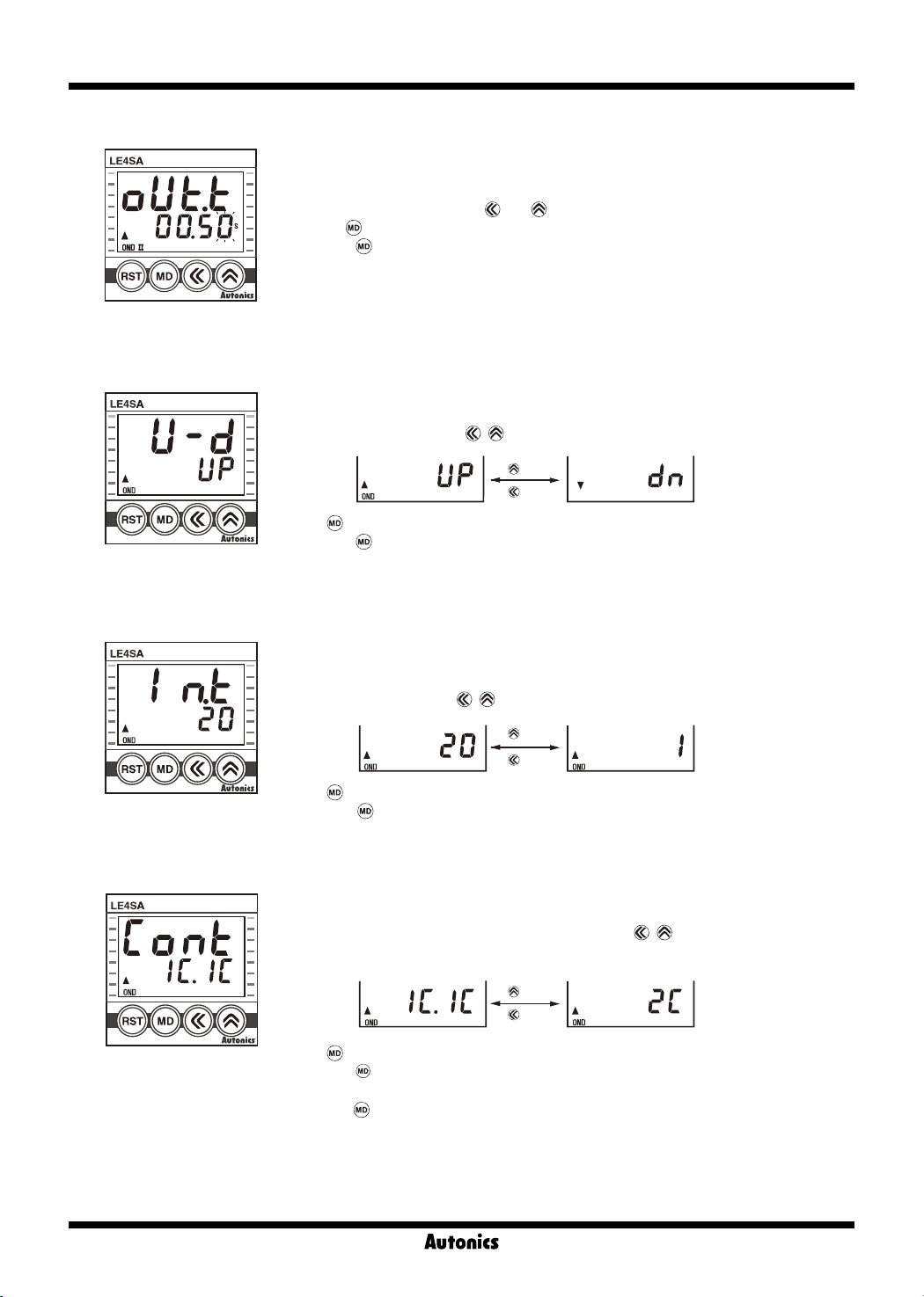
● One-shot output time setting
When output operation mode ON Delay 2[
1) In function setting mode, if it enter into One-shot output time setting mode as shown in
the [Fig. 2], the last digit will ash.
2) Set One-shot output time using
3) Pressing
4) If pressing
※
[Fig.2]
● Time progress UP/DOWN setting
Factory default
1) In function setting mode, if it advances to UP/DOWN setting mode, the characters will be
displayed as shown in the [Fig. 3].
2) Select UP(▲), DN(▼) using
],
ONd2
and key.(setting range: 0.01s to 99.99s)
key to complete one-shot output time setting and move to the next mode.
key for 3 sec. in any function setting mode, it will return to Run mode.
, key.
key
key
key to complete UP/DOWN setting and move to the next mode.
key for 3sec. in any function setting mode, it will return to Run mode.
[Fig.3]
※
Factory default
3) Press
4) If pressing
● The minimum input signal setting(LE4S only)
RESET, START and INHIBIT.
1) In function setting mode, if it enter into input signal setting mode, the characters will be
displayed as shown in the [Fig. 4].
2) Select 1ms or 20 ms using
[Fig.4]
※
Factory default
3) Press
4) If Pressing
key to complete input signal width and move to the next mode.
key over 3 sec. in any function setting mode, it will return to Run mode.
● Output contact setting(LE4SA only)
1) In function setting mode, if it enter into output contact setting mode, the characters will be
displayed as shown in the [Fig. 5].
2)Select time limit 1c+instant limit 1c or time limit 2c using
(Refer to LE4SA Connections on K-20 page for output contact connections)
, keys.
key
key
, keys.
key
key
K-28
[Fig.5]
※
Factory default
3) Press key to complete output contact setting and move to the next mode.
4) If pressing
※
Except for Star-Delta, Twin and Twin 1 modes(2C is set automatically)
※
If pressing
(If no key is pressed over 3 sec., it will enter into function setting mode.)
key for 3 sec. in any function setting, it will return to Run mode.
key in Run mode, output contact setting value will be displayed.
Page 10
LCD Timer(Touch Type)
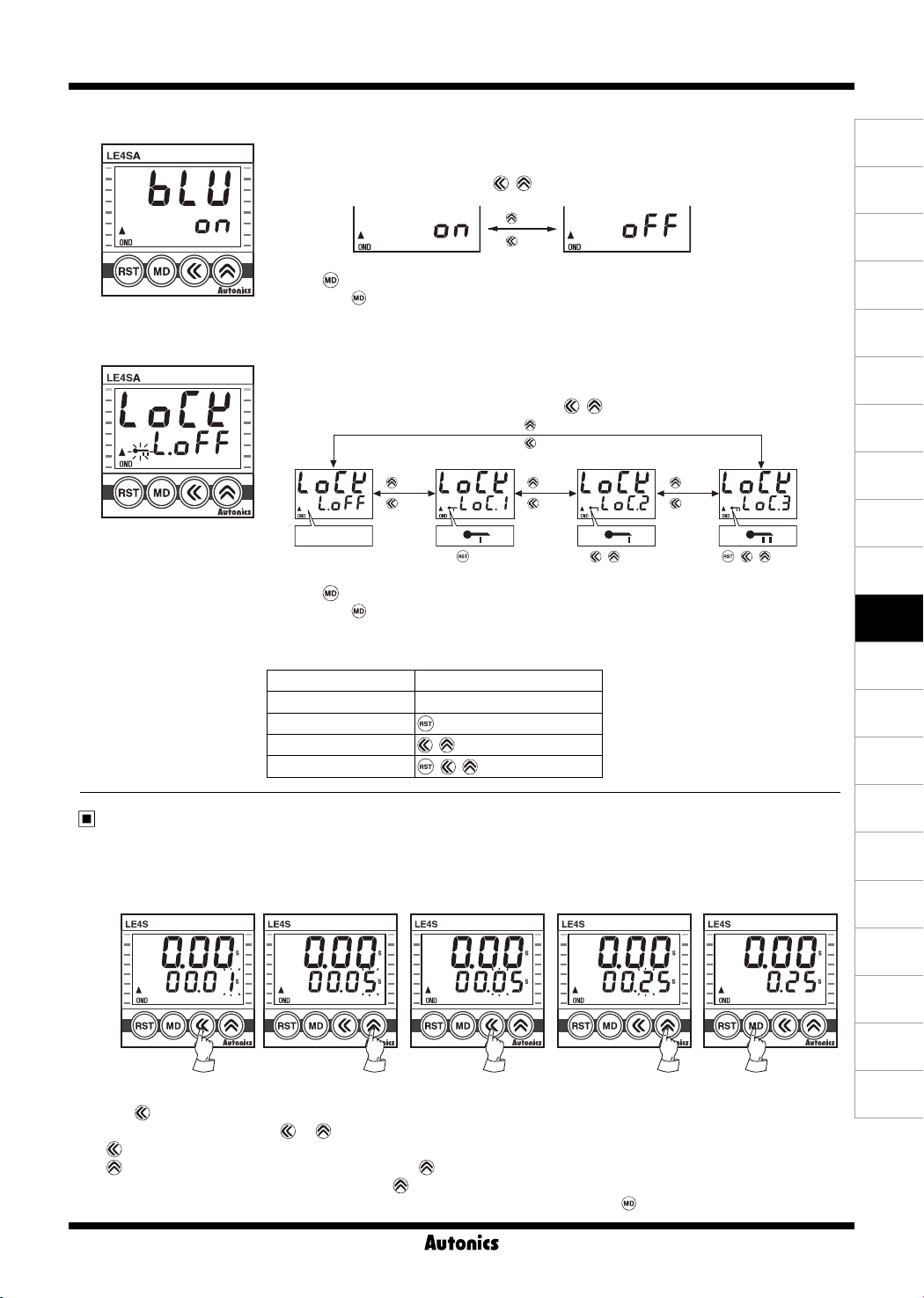
● Backlight ON/OFF setting
1) In function setting mode, if it enter into Backlight ON/OFF setting mode, the characters will
2) Select Backlight ON or
3) Press key to complete Backlight ON/OFF setting and move to the next mode.
[Fig.6]
※
Factory default
4) If pressing
● Key Lock setting
1) In function setting mode, if it enter into Key Lock setting mode, the characters will be
displayed as shown in the [Fig. 7].
2) Select
[Fig.7]
※
Factory default
3) Press
4) If pressing
※
※
Display Function
lOFF
LOc1
LOc2
LOc3
be displayed as shown in the [Fig. 6].
OFF
using
key for 3 sec. in any function setting mode, it will return to Run mode.
lOFF, LOc1, LOc2
Blank
Turns off
the Lock mode.
key
key
or
LOc3
key
cannot be used.
key to complete key lock setting and move to the next mode.
key for 3 sec. in any function setting mode, it will return to Run mode.
Factory default for LE4S is
and Factory default for LE4SA is
lOFF
Key Lock function
Turns off the key Lock mode.
key cannot be used.
, key cannot be used.
, , key cannot be used.
, key.
key
key
using , key.
key
key
key
key
cannot be used.
, key
key
key
cannot be used.
LOc1
, , key
.
(A)
Photo
electric
sensor
(B)
Fiber
optic
sensor
(C)
Door/Area
sensor
(D)
Proximity
sensor
(E)
Pressure
sensor
(F)
Rotary
encoder
(G)
Connector/
Socket
(H)
Temp.
controller
(I)
SSR/
Power
controller
(J)
Counter
(K)
Timer
(L)
Panel
meter
(M)
Tacho/
Speed/ Pulse
meter
(N)
Display
unit
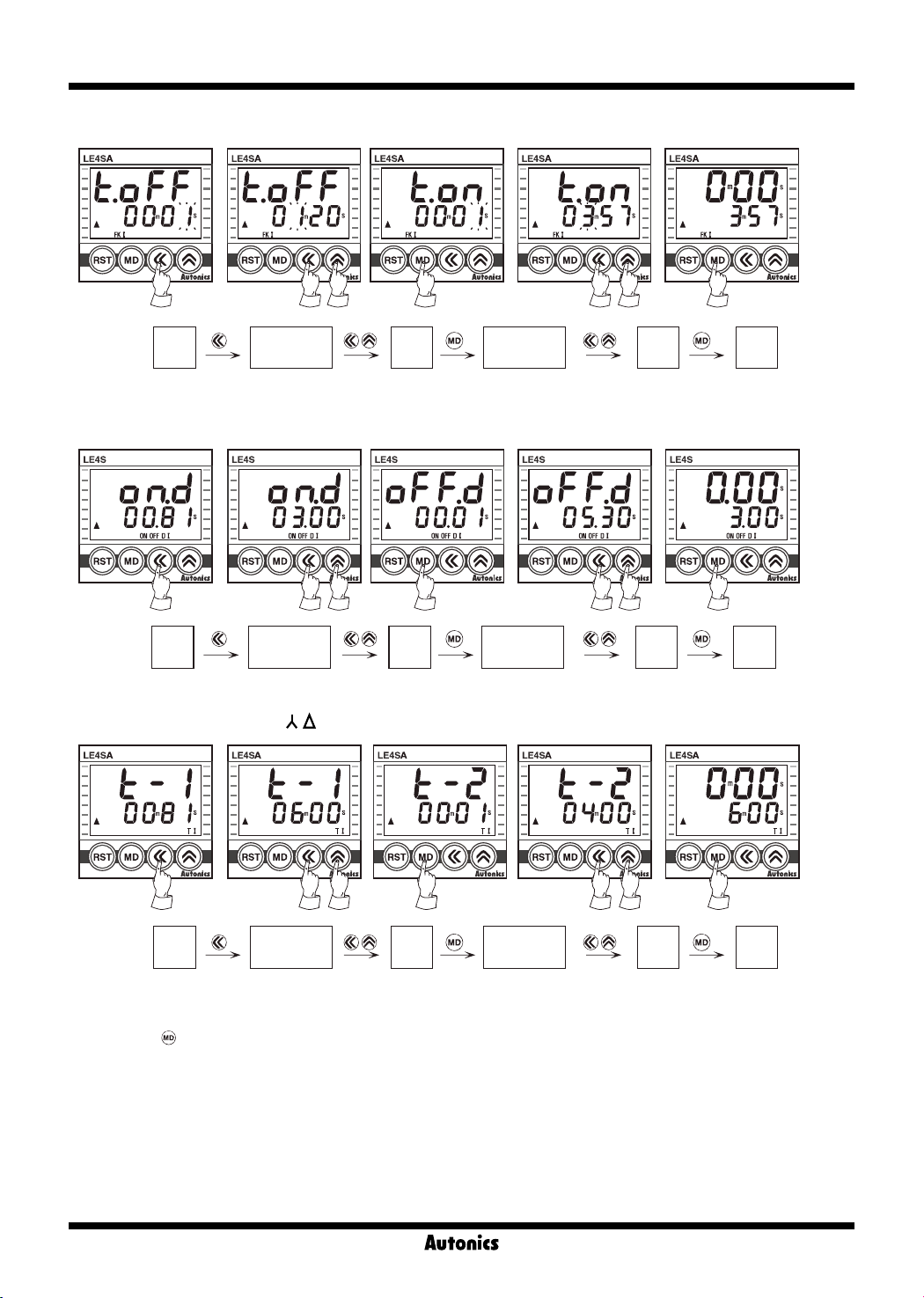
Setting time change
Please set operation time according to following instruction as the setting is different depending on the output operation
mode.
● Output operation mode : OND, ONDⅠ, ONDⅡ, INT, INTⅠ, OFF D
(LE4SA does not have no ONDⅠ, INTⅠ, OFF D.)
[Fig.1] [Fig.2] [Fig.3] [Fig.4] [Fig.5]
1) Press
2) Change setting time by using
-
number will increase faster by press
3) When the setting is completed, it will be stored and return to RUN mode by pressing
key in RUN mode, time set digits will ash.[Fig. 1]
or key.[Fig. 2,3,4]
key : Shift the setting digits.
key : Shift the ashing position value. As press key once, it will increase by 1digit,
key for over 2sec.
key.[Fig. 5]
K-29
(O)
Sensor
controller
(P)
Switching
mode power
supply
(Q)
Stepper
motor&
Driver&Controller
(R)
Graphic/
Logic
panel
(S)
Field
network
device
(T)
Software
(U)
Other
Page 11
LE4S Series
● Output operation mode : FK, FK I
Run
mode
Setting of
time
tOFF
Setting
the time
Setting of
tON
● Output operation mode : ON OFF D, ON OFF D I(LE4S only)
Run
mode
Setting of
OnD
● Output operation mode :
Setting
time
the time
- , T, TI (LE4SA only)
Setting of
OFfD
time
time
Setting
the time
Setting
the time
Run
mode
Run
mode
Run
mode
※
It is able to change the setting time during the time progressing, but be sure about the time progressing while changing
Setting of
time
T-1
Setting
the time
Setting of
time
T-2
Setting
the time
Run
mode
of the time.
※
If pressing
key while setting time is shorter than min. setting time, setting value will be ickering three times and it will
be returned to setting mode again, not to RUN mode.
※
If there is no additional key operations in 60 sec. after entering into setting mode, it will be return to RUN mode. (set
value is not stored.)
※
Min. setting time : 0.01 sec.
(In case of :
OND, ONd1, ONd2
modes, it is able to set "0" since no min. setting time is applied.)
K-30
Page 12
LCD Timer(Touch Type)
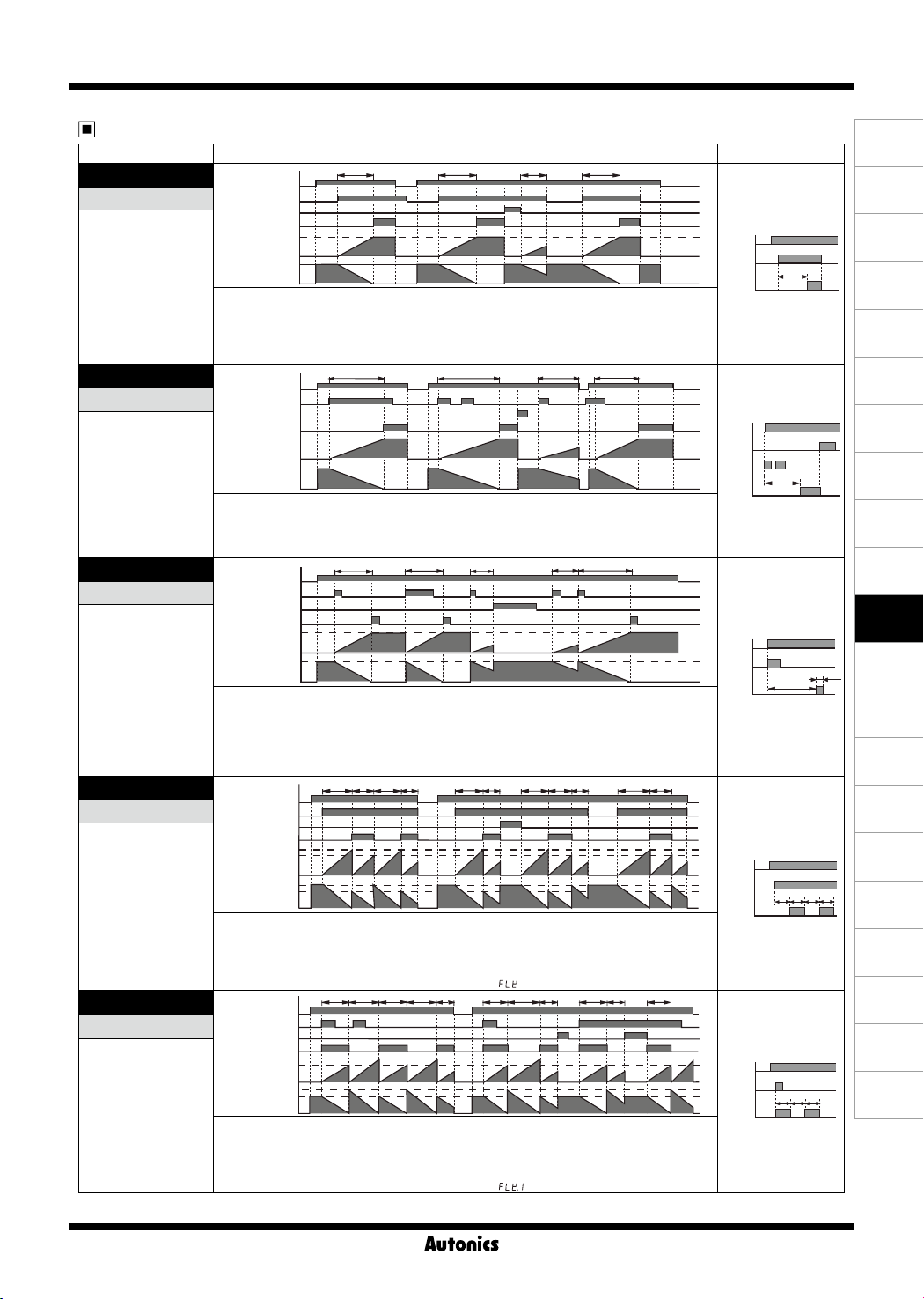
LE4S Output operation mode
Mode
]
[
OND
OND
ON Delay
T > Ta
[
]
ONd1
OND
Ⅰ
ON Delay 1
T > Ta
[
]
ONd2
OND
Ⅱ
ON Delay 2
(One-shot output)
T > Ta
[
]
FLK
FK
Flicker
(Toff operation
precedes)
Ton, Toff > Ta
[
]
FLk1
FK.
Ⅰ
Flicker 1
(Ton operation
precedes)
Ton, Toff > Ta
※
Initial status : UP mode-display value is "0", output is "OFF". DOWN mode-display value is "setting time", output is "OFF".
Time chart Operation
POWER
START
RESET
RELAY OUT
Set time
UP
0
Set time
DOWN
POWER
START
RESET
RELAY OUT
Set time
UP
Set time
DOWN
POWER
START
RESET
RELAY OUT
Set time
UP
Set time
DOWN
POWER
START
RESET
RELAY OUT
Toff
Ton
UP
Toff
Ton
DOWN
POWER
START
RESET
RELAY OUT
Toff
Ton
UP
Toff
Ton
DOWN
0
0
0
0
0
0
0
0
0
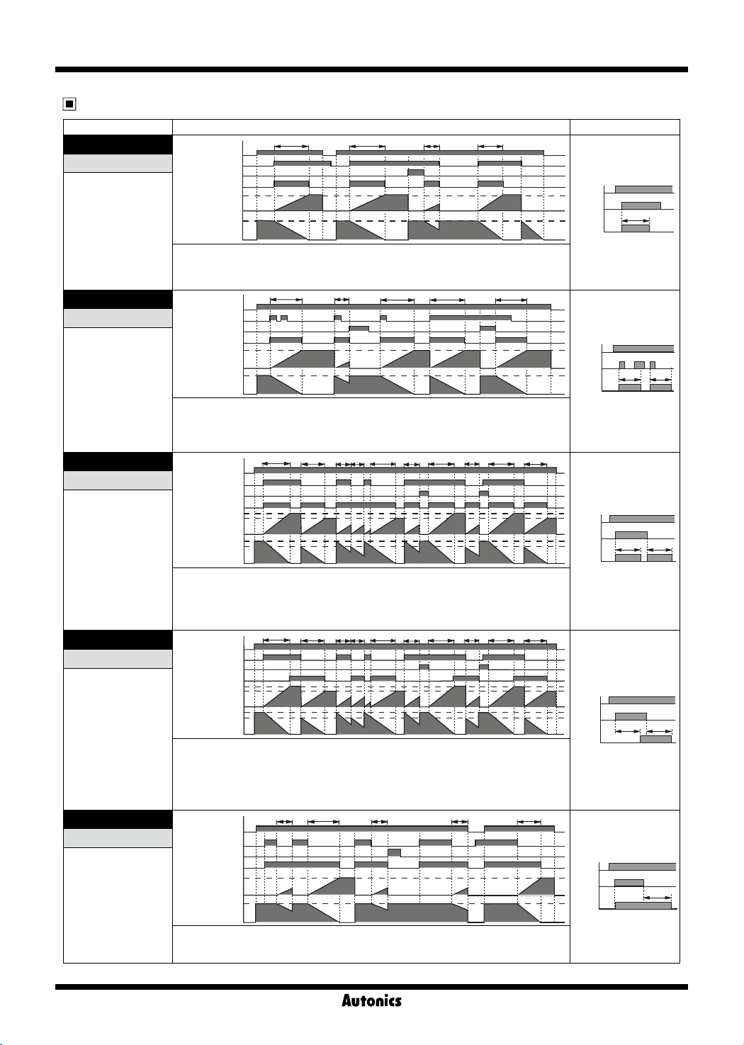
1. Timing operation starts when START signal is ON at status of power on.
2. Output will be ON when timing operation is progressed up to the setting time. Display value will be
HOLD. (① position)
3. When RESET signal is ON, display value and output will be reset.(② position)
4. If RESET signal is OFF while START signal is ON,“STEP 1”will be restarted.(③ position)
5. When START signal is OFF, display value and output will be reset.(④ position)
1. Timing operation starts when START signal is ON at status of power on.
2. Output will be ON when timing operation is progressed up to the setting time. Display value will be
HOLD.(① position)
3. Even though START signal is applied repeatedly, only the initial signal is recognized.(② position)
4. When RESET signal is ON, display value and output will be reset.(③ position)
1. Timing operation starts when START signal is ON at status of power on.
2. Time limit output will be ON and goes OFF during Tout setting time when timing operation is progressed
up to the setting time. Display value will be HOLD.(① position)
3. When RESET signal is ON, display value and output will be reset.
4. If START signal is applied while time is progressing, Timing operation will be reset and started again. (②
position)
5. Tout setting range: 0.01 sec to 99.99 sec.
1. If START signal is ON, output will be repeatedly OFF during Toff setting time and will be OFF during Ton
setting time when power is ON.
2. When RESET signal is ON, display value and output will be reset.
3. If RESET signal is OFF when START signal is ON, “STEP 1” will be restarted.
4. When START signal is OFF, display value and output will be reset.
5. It is able to set each Toff time and Ton time separately. In [
1. IF START signal is ON, output will be repeatedly ON during Ton setting time and will be OFF during Toff
setting time when power is ON.
2. Even though START signal is applied repeatedly, only the initial signal is recognized.(① position)
3. When START signal is ON, display value and output will be reset. If START signal is ON, it will be
restarted.
4. It is able to set each Toff time and Ton time separately. In [
T T
①
T T
①
T T
①
Toff Toff Toff Toff ToffTon Ton
Ta Ta Ta
Toff
Toff
①
② ③
②
Ta Ta Ta
③
] mode, timing operation starts with Toff.
ToffTon Ton Ton Ton
] mode, timing operation starts with Ton.
TTa
④
TTa
TTa Ta
②
Ton
Ton
T = Setting time, T > Ta
POWER
START
RELAY
T = set time
POWER
RESET
START
RELAY
OUT
T = set time
POWER
START
RELAY
OUT
Tout = output time
T = set time
POWER
START
RELAY
OUT
Ton, Toff = set time
Enables to set Ton and
Toff time differently.
POWER
START
RELAY
OUT
Ton, Toff = set time
Enables to set Ton and
Toff time differently.
T
OUT
T
T
Toff Ton Toff Ton
Ton Toff Ton
Tout
(A)
Photo
electric
sensor
(B)
Fiber
optic
sensor
(C)
Door/Area
sensor
(D)
Proximity
sensor
(E)
Pressure
sensor
(F)
Rotary
encoder
(G)
Connector/
Socket
(H)
Temp.
controller
(I)
SSR/
Power
controller
(J)
Counter
(K)
Timer
(L)
Panel
meter
(M)
Tacho/
Speed/ Pulse
meter
(N)
Display
unit
(O)
Sensor
controller
(P)
Switching
mode power
supply
(Q)
Stepper
motor&
Driver&Controller
(R)
Graphic/
Logic
panel
(S)
Field
network
device
(T)
Software
(U)
Other
K-31
Page 13
LE4S Series
LE4S Output operation mode
T = Setting time, T > Ta
Mode Time chart Operation
]
[
INT
INT
Interval
T > Ta
[
]
INt1
INT
Ⅰ
Interval 1
T > Ta
[
]
NFD
ON OFF D
ON-OFF Delay
T > Ta
[
]
NFd1
ON OFF D
ON-OFF Delay 1
T > Ta
[
OFD
OFF D
OFF Delay
T > Ta
※
Ⅰ
]
Initial status : UP mode-display value is "0", output is "OFF". DOWN mode-display value is "setting time", output is "OFF".
POWER
START
RESET
RELAY OUT
Set time
UP
0
Set time
DOWN
POWER
START
RESET
RELAY OUT
Set time
UP
Set time
DOWN
POWER
START
RESET
RELAY OUT
Toff
Ton
UP
Toff
Ton
DOWN
POWER
START
RESET
RELAY OUT
Toff
Ton
UP
Toff
Ton
DOWN
POWER
START
RESET
RELAY OUT
Set time
UP
Set time
DOWN
0
0
0
0
0
0
0
0
0
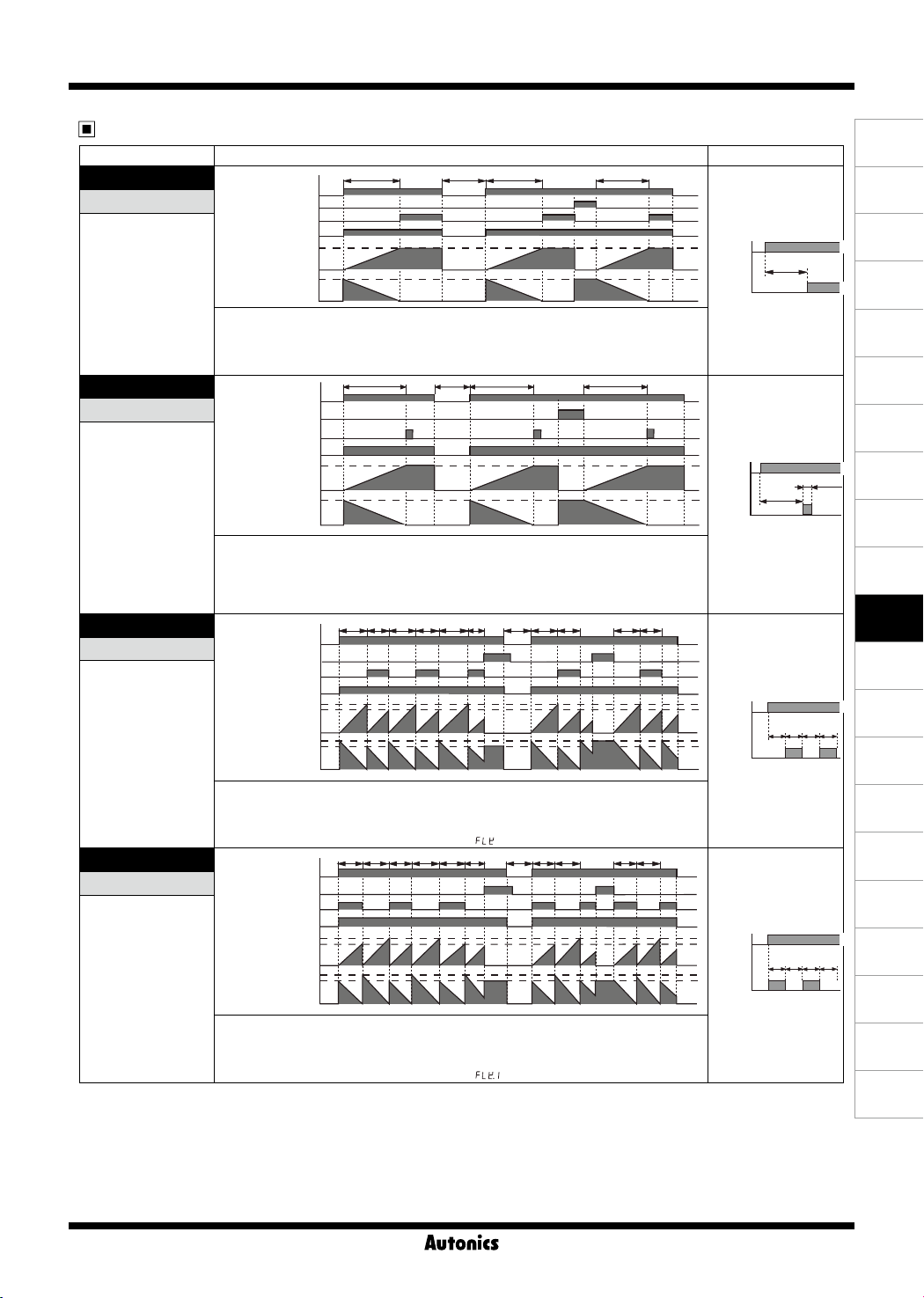
1. Output will be ON when START signal is ON at status of power on and Timing operation starts.
2. Output will be OFF when timing operation is progressed up to the setting time. Display value will be HOLD.
3. When RESET signal is ON, display value and output will be reset.(① position)
4. If RESET signal is OFF when START signal is ON,“STEP 1” will be restarted.
5. When START signal is OFF, display value and output will be reset.(② position)
1. Output will be ON when START signal is ON at status of power on and Timing operation starts.
2. Output will be OFF when timing operation is progressed up to the setting time. Display value will be HOLD.
3. Even though START signal is applied repeatedly, only the initial signal is recognized.(① position)
4. If START signal is ON after timing operation is progressed up to the setting time, Output will be ON and setting
time will be reset and then timing setting starts.
5. When RESET signal is ON, display value and output will be reset.(② position)
1. If START signal is ON when power is on, Output will be ON when timing operation is progressed up to the Ton
setting time(On-Delay). IF START signal is OFF, output will be ON when timing operation is progressed up to
the Toff setting time (OFF-Delay).
2. If START signal is applied repeatedly, output is ON and display value will be reset.(① position)
3. When RESET signal is ON, display value and output will be reset. When RESET signal is OFF while START
signal is ON, it will be operating as On-Delay.(② position)
4. It is able to set each Toff time and Ton time separately.
1. If START signal is ON when power is on, timing operation starts. Output will be ON when timing operation
is progressed up to the Ton setting time(On-Delay). IF START signal is OFF, output will be ON when timing
operation is progressed up to the Toff setting time (OFF-Delay).
2. Output will be ON when START signal is ON and goes OFF during setting time and display value will be reset.(① position)
3. Output will be OFF when START signal is OFF and goes ON during setting time and display value will be reset.(① position)
4. When RESET signal is ON, display value and output will be reset. When RESET signal is OFF while START
signal is ON, it will be operating as On-Delay.(② position)
5. It is able to set each Toff time and Ton time separately.
1. If START signal is ON when power is on, output will be ON.
2. When START signal is OFF, timing operation starts. Output will be OFF when timing operation is progressed up
to the setting time. Display value will be HOLD.
3. When RESET signal is ON, display value and output will be reset.
T T
T T T TTa
①
Toff
Toff
T TTa Ta Ta
②
①
ToffTon TonTon TaTaTa Ta
① ②
ToffTon TonTon TaTaTa Ta
① ②
TTa
POWER
START
RELAY
OUT
T = set time
②
POWER
START
RELAY
T = set time
Toff
POWER
START
RELAY
OUT
Ton, Toff = set time
Toff
POWER
START
RELAY
OUT
Ton, Toff = set time
POWER
START
RELAY
OUT
T = set time
T T
OUT
Ton Toff
Ton Toff
K-32
T
T
Page 14
LCD Timer(Touch Type)
LE4SA Output operation mode
T = Setting time, T > Ta, Rt = Reset time
Mode Time chart Operation
]
[
OND
OND
ON Delay
1. Timing operation starts when power is ON.
2. Time limit output will be ON when timing operation is progressed up to the setting time. Display value will be
3. If selecting time limit 1c + instantaneous 1c mode, instantaneous output will be ON when power is ON and goes
4. If pressing RESET key, display value and time limit output will be reset.
[
]
ONd2
OND
Ⅱ
ON Delay 2
(One-shot output)
[
]
FLK
FK
Flicker
(Toff operation
precedes)
Ton, Toff > Ta
[
]
FLk1
FK
Ⅰ
Flicker 1
(Ton operation
precedes)
※
Initial status : UP mode-display value is "0", output is "OFF". DOWN mode-display value is "setting time", output is "OFF".
※
Instantaneous contact(OUT2) will be returned when power is off.
※
RESET key is locked for default set and release the lock to use.
1. Timing operation starts when power is ON.
2. Time limit output will be ON during Tout setting time and goes OFF when timing operation is progressed up to
3. If selecting time limit 1c + instantaneous 1c mode, instantaneous output will be ON when power is ON and goes
4. If pressing RESET key, display value and time limit output will be reset.
5. Tout setting range: 0.01 sec to 99.99 sec.
1. Control output will be repeatedly OFF during Toff setting time and will be ON during Ton setting time when
2. If selecting time limit 1c + instantaneous 1c mode, instantaneous output will be ON when power is ON and goes
3. If pressing RESET key, display value and time limit output will be reset.
4. It is able to set each Toff time and Ton time separately. In [
1. Control output will be repeatedly ON during Ton setting time and will be OFF during Toff setting time when
2. If selecting time limit 1c + instantaneous 1c mode, instantaneous output will be ON when power is ON and goes
3. If pressing RESET key, display value and time limit output will be reset.
4. It is able to set each Ton time and Toff time separately. In [
POWER
※
RESET
Time limit contact
Instantaneous contact
HOLD.
OFF when power is OFF.
Instantaneous contact
the setting time. Display value will be HOLD.
OFF when power is OFF.
Instantaneous contact
power is ON.
OFF when power is OFF.
Instantaneous contact
power is ON.
OFF when power is OFF.
(⑧-⑥)
(①-③)
Set time
UP
Set time
DOWN
POWER
※
RESET
Time limit contact
(⑧-⑥)
(①-③)
Set time
UP
Set time
DOWN
POWER
※
RESET
Time limit contact
(⑧-⑥)
(①-③)
Toff
Ton
UP
Toff
Ton
DOWN
POWER
※RESET
Time limit contact
(⑧-⑥)
(①-③)
Toff
Ton
UP
Toff
Ton
DOWN
0
0
0
0
0
0
0
0
T T TRt
T T TRt
RtToff Toff Toff ToffToff Ton Ton Ton TonTa
] mode, timing operation starts with Toff.
RtToff Ton Toff ToffToffTon Ton Ton TonTa
] mode, timing operation starts with Ton.
POWER
Time limit
contact
output
T = set time
POWER
Time limit
contact
output
Tout = output time
T = set time
POWER
Time limit
contact
output
Ton, Toff = set time
Enables to set Ton and
Toff time differently.
POWER
Time limit
contact
output
Ton, Toff = set time
Enables to set Ton and
Toff time differently.
(A)
Photo
electric
sensor
(B)
Fiber
optic
sensor
(C)
Door/Area
sensor
T
T
Toff
Ton
Toff
Ton
Toff ToffTon
Tout
Ton
(D)
Proximity
sensor
(E)
Pressure
sensor
(F)
Rotary
encoder
(G)
Connector/
Socket
(H)
Temp.
controller
(I)
SSR/
Power
controller
(J)
Counter
(K)
Timer
(L)
Panel
meter
(M)
Tacho/
Speed/ Pulse
meter
(N)
Display
unit
(O)
Sensor
controller
(P)
Switching
mode power
supply
(Q)
Stepper
motor&
Driver&Controller
(R)
Graphic/
Logic
panel
(S)
Field
network
device
(T)
Software
(U)
Other
K-33
Page 15
LE4S Series
LE4SA Output operation mode
Rt : Reset time(Min. 500ms)
Mode Time chart Operation
[
]
INT
Interval
POWER
※
RESET
Time limit contact
Instantaneous contact
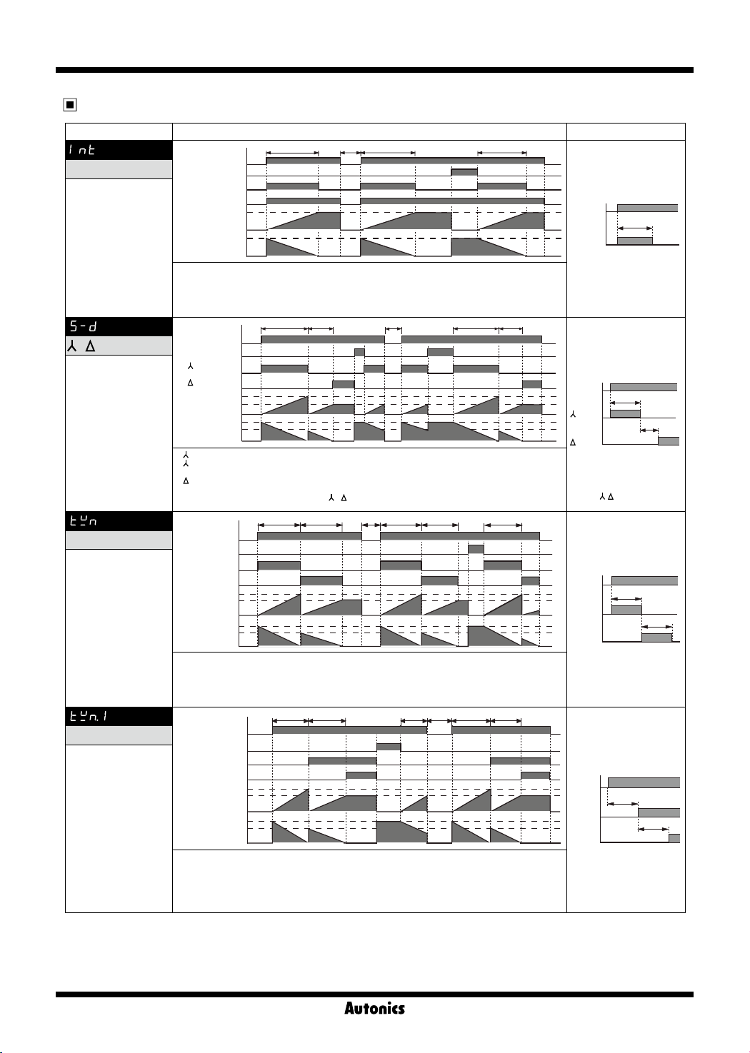
1. Time limit output will be ON when power is ON and Timing operation starts.
2. Time limit output will be OFF when timing operation is progressed up to the setting time. Display value will be
3. If selecting time limit 1c + instantaneous 1c mode, instantaneous output will be ON when power is ON and
4. If pressing RESET key, display value and time limit output will be reset.
(⑧-⑥)
(①-③)
Set time
UP
DOWN
HOLD.
goes OFF when power is OFF.
Set time
0
0
[ ]
-
Star-Delta
(Output will be set
automatically
as Time limit 2c)
POWER
※
RESET
contact(⑧-⑥)
contact(①-③)
T1
Set time
T2
Set time
0
T1
T2
0
UP
DOWN
1. contact will be ON when power is ON and Timing operation starts.
contact will be OFF when timing operation is progressed up to the T1 setting time.
2.
Timing operation will be reset and started again.
contact will be ON when timing operation is progressed up to the T2 switching time.
3.
Display value will be HOLD.
4. If pressing RESET key, display value and
5. It is able to set each T1 and T2 time separately.
[ ]
T
Twin
(Output will be set
automatically
as Time limit 2c)
POWER
※
RESET
T1 contact(⑧-⑥)
T2 contact(①-③)
T1
Set time
T2
UP
DOWN
1. T1 contact will be ON when power is ON and Timing operation starts.
2. T1 contact will be OFF and T2 contact will be ON when timing operation is progressed up to the T1 setting
time. Timing operation will be reset and started again. T2 contact will be OFF when timing operation is progressed up to the T2 setting time. Display value will be HOLD.
3. If pressing RESET key, display value and T1, T2 contacts will be reset.
4. It is able to set each T1 and T2 time separately.
Set time
0
T1
T2
0
[ ]
T
Ⅰ
Twin 1
(Output will be set
automatically
as Time limit 2c)
※
Initial status : UP mode-display value is "0", output is "OFF". DOWN mode-display value is "setting time", output is "OFF".
※
Instantaneous contact(OUT2) will be returned when power is off.
※
RESET key is locked for default set and release the lock to use.
POWER
※
RESET
T1 contact(⑧-⑥)
T2 contact(①-③)
1. Timing operation starts when power is ON.
2. T1 contact will be ON when timing operation is progressed up to the T1 setting time. Timing operation will be
reset and started again.
3. T2 contact will be ON when timing operation is progressed up to the T2 setting time. Display value will be
HOLD.
4. If pressing RESET key, display value and T1 and T2 contacts will be reset.
5. It is able to set each T1 and T2 time separately.
Set time
UP
Set time
DOWN
T1
T2
0
T1
T2
0
T T TRt
T1 T2 T1 T2Rt
- contacts will be reset.
T1 T1T2 T2Rt T1
T1 T1Ta T2T2 Rt
POWER
Time limit
contact
output
T = set time
POWER
contact
contact
※
T1 : set time
T2 : switching time
(
POWER
T1 contact
T2 contact
T1, T2 = set time
Enables to set T1 and T2
time same or differently
POWER
T1 contact
T2 contact
T1, T2 = set time
Enables to set T1 and T2
time same or differently
T
T1
T2
- switching time)
T1
T2
T1
T2
K-34
Page 16
LCD Timer(Touch Type)
Proper usage
Caution
It may give an electric shock if touch the input signal
terminal(Between START, RESET, INHIBIT and terminal
) when the power is supplied.
②
Power connection
● Connect AC power line between (
AC power type. Be careful of power connection for DC
power type. (
②← ⊖, ⑦ ← ⊕
)
● LE4S, LE4SA work stably within range of rated power.
(If using power line with another high voltage line or
energy line in the same conduit, it may cause inductive
voltage.
Therefore please use seperate conduit for power line)
Power start
● Caution for power rising time(100ms) after power on and
power falling time(100ms) after power off.
ON
Power
OFF
100
ms
The unstable time
against the input signal
● Power ON Start
LE4SA model is starting after 100ms of supplying the
power due to rising time of other devices (sensor, etc.)
(refer to the above gure.)
For ower ON Start, under 100ms setting may cause
unstable operation. (it operates normally over 100ms
setting)
For using under 100ms time operation, use LE4S, Signal
ON Start type.
● Supply the power at once by a switch or relay contact,
otherwise it may cause timing error.
Input/Output
● Power terminal and Input terminal have not been
insulated because there is no power transformer in this
Timer.
When using the sensor of SSR output type with input
①
terminal of timer, please check whether Double insulated
or not.
Please use double insulated relay when connecting
②
relay output with input terminal.
● Please use 8 Pin socket when connecting this Timer
with other equipment and do not touch the socket when
power on.
● Please use Power supply with over current protection
circuit.(250V 1A fuse)
● When using relay contact as input signal, please use a
contact that can function reliable at 5VDC, 1mA.
● In case of connecting START terminal (③) and power
terminal (②) of LE4S, do not use it to start at the same
time applying power.
● LE4S is transformer less type, therefore please check
following for connecting relay contact for input signal and
transistor.
) for LE4S, LE4SA
②-⑦
100
ms
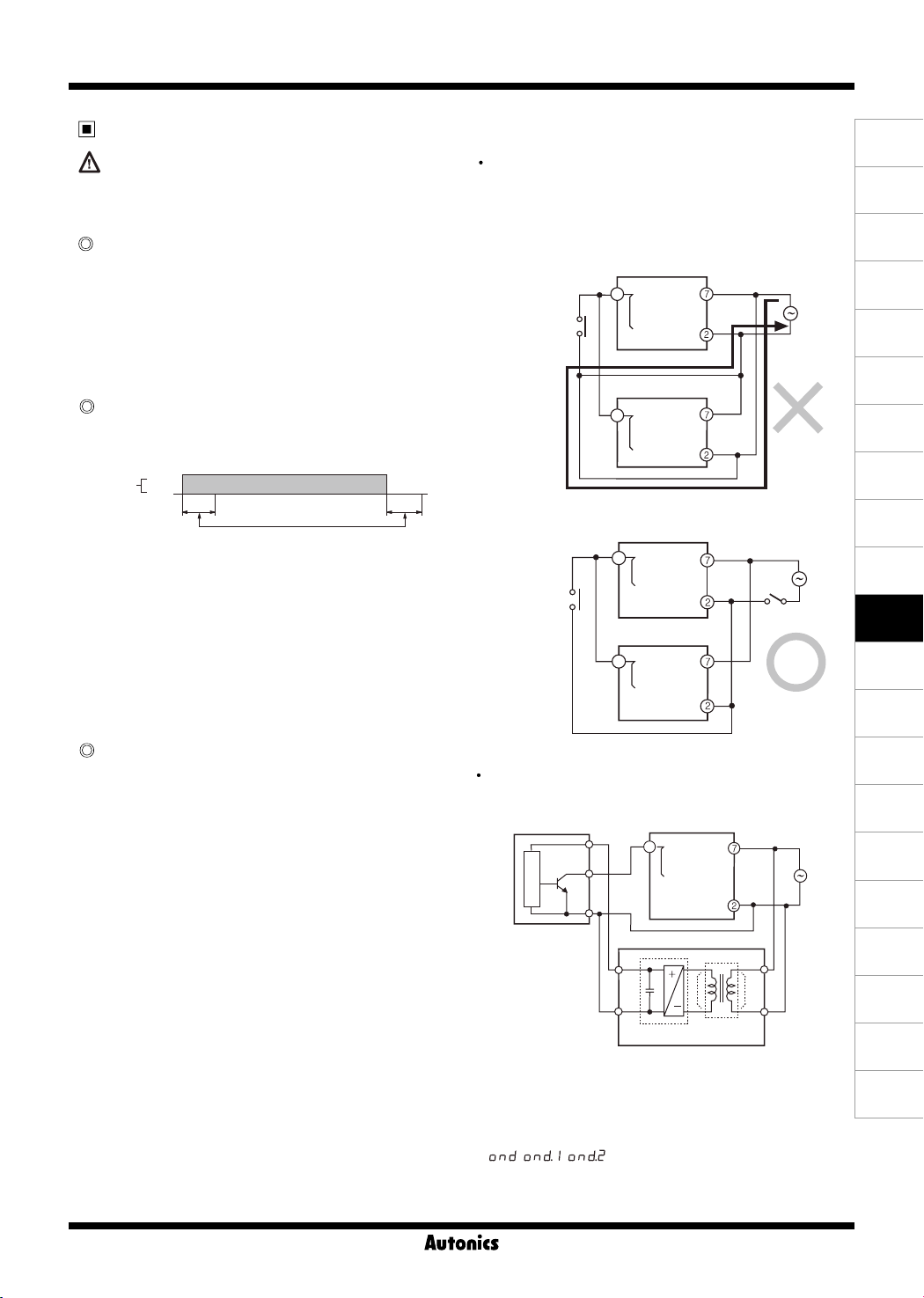
When connecting more than 2 timers with 1 relay contact
for input or transistor, please wire following <Fig. 2 >.
Please use relay contact or transistor to start.
(Time error can occurs under 100ms setting because of
rising time of Timer).
LE4S
START
③
RESET
Input contact
or transistor
Shortcircuit
current
INHIBIT
LE4S
START
RESET
INHIBIT
④
①
③
④
①
Power
LE4S
START
③
RESET
Input contact
or transistor
INHIBIT
④
①
Power
LE4S
START
③
RESET
④
INHIBIT
①
< Fig. 2 >
Please use transfomer with primary and secondary
isolated for input.
LE3SSensor
START
③
RESET
Main circuit
INHIBIT
Rectication
circuit
④
①
Transformer
with isolation
Power
< External sensor power supply >
● Be sure that the specications of this unit. Because
when supplying the power to LE4SA, this unit operates
instantly. (If supplying the power without the right
checking, it may cause malfunction.)
● , , operation modes are available to set
as "0".
(A)
Photo
electric
sensor
(B)
Fiber
optic
sensor
(C)
Door/Area
sensor
(D)
Proximity
sensor
(E)
Pressure
sensor
(F)
Rotary
encoder
(G)
Connector/
Socket
(H)
Temp.
controller
(I)
SSR/
Power
controller
(J)
Counter
(K)
Timer
(L)
Panel
meter
(M)
Tacho/
Speed/ Pulse
meter
(N)
Display
unit
(O)
Sensor
controller
(P)
Switching
mode power
supply
(Q)
Stepper
motor&
Driver&Controller
(R)
Graphic/
Logic
panel
(S)
Field
network
device
(T)
Software
(U)
Other
K-35
Page 17
LE4S Series
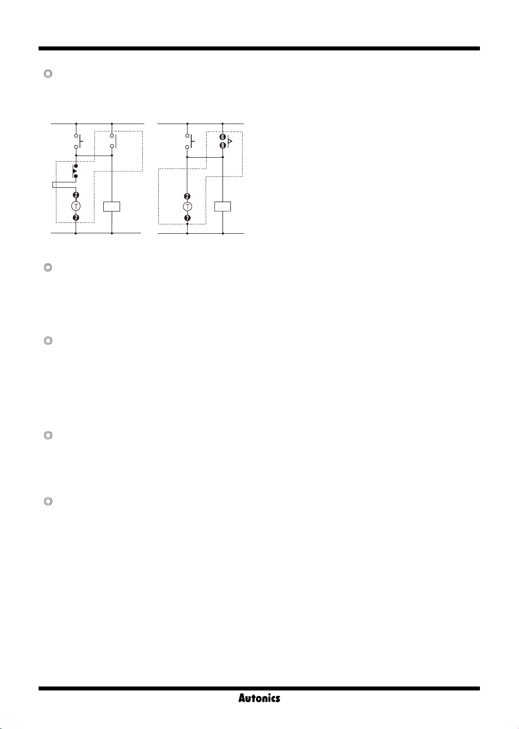
Interval mode
It is able to make Instantaneous ON and time limit OFF
(Holding device) with using interval mode.
T : Timer
START
Time
limit
<Previous>
Instan-
taneous
Load Load
START
LE4S
<Interval mode>
Time
limit
Change of output operation mode and
timer range
If changing output operation mode or time range,previous
reset value will be deleted.
But, UP/DOWN selection mode and lock mode are
exception.
Change of preset value
● If changing setting value while time progressing, new
preset value should be higher than previous preset
value.
Otherwise output may work while changing setting
value.
● If changing setting value while it is running, it will work as
changed setting value. Please use lock function in order
to avoid malfunction.
Noise
We test 2kV, pulse width 1㎲ against Impulse voltage
between power terminals and 1kV, pulse width 1㎲ at noise
simulator against external noise voltage. Please install MP
condensor (0.1 to 1㎌) or oil condensor between power
teminals when over impulse noise voltage occurs.
Environment
Please avoid the following places;
● Where this product may be damaged by strong impact or
vibration.
● Where there are corrosive gas or ammable gas and
water, oil, dust exist.
● Where magnetic and electrical noise occurs.
● Where there are high temperature and humidity beyond
rated specication.
● Where there are strong alkalis and acids.
● Where there are direct rays of sun.
K-36
 Loading...