

Multi Indicator
KN-2000W SERIES
M A N U A L
Thank you very much for selecting Autonics products.
For your safety, please read the following before using.
Caution for your safety
Please keep these instructions and review them before using this unit.
※
※
Please observe the cautions that follow;
Warning
Caution
※
The following is an explanation of the symbols used in the operation manual.
Caution: Injury or danger may occur under special conditions.
Warning
1. In case of using this unit with machinery(Ex: nuclear power control, medical
equipment, ship, vehicle, train, airplane, combustion apparatus, safety
device, crime/disaster prevention equipment, etc) which may cause damages
to human life or property, it is required to install fail-safe device.
It may cause a re, human injury or damage to property.
2. Install this unit on a panel.
It may cause electric shock.
3. Do not connect, repair, or inspect this unit when power is ON.
It may cause electric shock.
4. Do not disassemble the case. Please contact us if it is required.
It may cause electric shock or a re.
5. Wire properly after checking terminal numbers.
It may cause a re.
Caution
1. This unit shall not be used outdoors.
It might shorten the life cycle of the product or cause electric shock.
2. Please observe the rated specications.
It might shorten the life cycle of the product or cause a re.
3. In cleaning this unit, do not use water or organic solvent. And use dry cloth.
It may cause electric shock or a re.
4. Do not use this unit where there are ammable or explosive gas, humidity,
direct ray of the sun, radiant heat, vibration and impact etc.
It may cause a re or explosion.
5. Do not inow dust or wire dregs into the unit.
It may cause a re or malfunction.
6. Wire it properly after checking terminal numbers when connecting power
cable and measuring input.
It may cause a re or explosion.
Ordering information
KN-2 0 0 0 W
The above specifications are subject to change without notice.
Serious injury may result if instructions are not followed.
Product may be damaged, or injury may result if instructions are not followed.
Size
W DIN W96×H48 mm
Power supply
0 100-240 VAC 50 to 60 Hz
1 24 VDC
0 No option
Option output
1 Transmission output (4-20 mA)
4 RS485 communication output
Transmission output (4-20 mA)
5
+ RS485 communication output
Alarm output
0 No alarm output
2 2EA alarm output
4 4EA alarm output
Item
KN-2 Multi Indicator
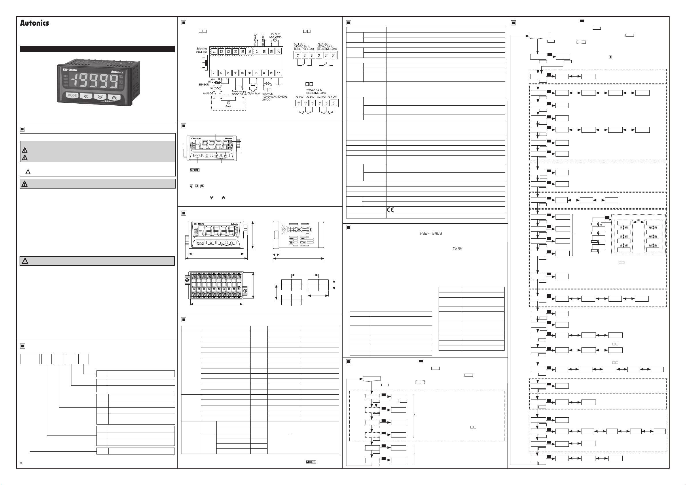
Connections
● KN-20 W
RTD/TC/mV/±1V
-1~+10V
0~20mA
transmitter
● KN-22 W
● KN-24 W
F.G.
Part descriptions
1
3
4 6
4.
key
: Used to enter parameter set mode, move to parameters, save SV and return to
RUN mode.
5.
, , key: Used to change parameter SV.
6.
D.IN3
: Press the
and keys for 3 sec. at the same time, it operates the set function
(alarm clear, display hold, zero-point adjustment) at [DI-K] at program mode.
1.
Display part(red)
●Run mode: Displays current measurement value.
2
●Parameter set mode: Displays parameter and SV.
2.
Unit indicator: Displays the set unit.
5
3.
Alarm output indicator
: Turns ON when the alarm is ON.
Dimensions
48
108
96
10
90
● Panel cut-out
Min. 116
44.8
Min. 52
91
Input type and range
Input type
K(CA)
J(IC)
E(CR)
T(CC)
R(PR)
B(PR)*
Thermo
-couple
S(PR)*
N(NN)*
C(W5)*
L(IC)*
U(CC)*
Platinel II*
Cu50Ω*
Cu100Ω*
RTD
JPt100Ω
DPt50Ω
DPt100Ω
Current
Analog
Voltage
※
Above input types which have the * mark are not displayed.
0.00 - 20.00 mA
4.00 - 20.00 mA
-50.00 - 50.00 mV
-200.0 - 200.0 mV
-1.0000 - 1.0000 V
-1.000 - 10.000 V
To display the above input types, supply the power with pressing the key.
Parameter
TC-K
TC-J
TC-E
TC-T
TC-R
TC-B
TC-S
TC-N
TC-C
TC-L
TC-U
TC-P
Cu50
Cu10
JPt1
DPt5
DPt1
aMA1
aMA2
aMV1
aMV2
A-V1
A-V2
Input range(℃) Input range(℉)
-200.0 to 1350.0 -328 to 2462
-200.0 to 800.0 -328.0 to 1472.0
-200.0 to 800.0 -328.0 to 1472.0
-200.0 to 400.0 -328.0 to 752.0
0.0 to 1750.0 32 to 3182
400.0 to 1800.0 752 to 3272
0.0 to 1750.0 32 to 3182
-200.0 to 1300.0 -328 to 2372
0 to 2300 32 to 4172
-200.0 to 900.0 -328.0 to 1652.0
-200.0 to 400.0 -328.0 to 752.0
0.0 to 1390.0 32 to 2534
-200.0 to 200.0 -328.0 to 392.0
-200.0 to 200.0 -328.0 to 392.0
-200.0 to 600.0 -328.0 to 1112.0
-200.0 to 600.0 -328.0 to 1112.0
-200.0 to 850.0 -328.0 to 1530.0
19999 to 19999
(display range is variable
depending on decimal point position)
92
(unit: mm)
+0.6
0
Specication
Series KN-2000W
Power
supply
Allowable voltage range 90 to 110% of rated voltage
Power
consumption
Display method 4½ digit: 7 Segment LED Display(red, green, yellow), character size: W10 ×H17mm
Input type
Digital input
Sub
output
Display accuracy
Setting method Set by front keys or RS485 communication
Alarm output hysteresis Set ON/OFF interval (1 to 999 digit)
Sampling cycle Analog input : 100 ms, Temperature sensor input : 250 ms
Dielectric voltage 200 0VAC 50/60 Hz for 1 min. (between input terminal and power terminal)
Vibration
Relay
life
cycle
Insulation resistance Min. 100 MΩ (at 500VDC megger)
Noise resistance Square shaped noise by noise simulator (pulse width 1 ㎲) ±2 kV
Memory retention Approx. 10 years (non-volatile semiconductor memory type)
Environ
-ment
Approval
Unit weight Approx. 200 g
※
■
AC voltage 100-240 VAC 50 to 60 Hz
DC voltage 24 VDC
AC voltage Max. 8 VA
DC voltage Max. 3 W
RTD JPt100Ω, DPt100Ω, DPt50Ω, Cu50Ω, Cu100Ω (5 types)
Thermocouple K, J, E, T, R, B, S, N, C (W5), L, U, PLII (12 types)
Analog
Alarm output
Transmission
output
Com. output RS485 (Modbus RTU)
2-point
4-point
Ambient temp. -10 to 50 ℃, storage: -20 to 60 ℃
Ambient humi. 35 to 85%RH, storage: 35 to 85%RH
Environment resistance is rated at no freezing or condensation.
Communication
●Voltage : ±1.0000 V, ±50.00 mV, ±200.0 mV, -1.000 V-10.000 V (4 types)
●Current : 4.00-20.00 mA, 0.00-20.00 mA (2 types)
●Contact input : Max. 2 kΩ in ON,Max. 90 kΩ in OFF
●Non-contact input : Residual voltage max. 1.0 V in ON,
Leakage current max. 0.03 mA in OFF
●Outow current : Approx. 0.2 mA
2-point : Relay contact capacity 250 VAC 3 A 1c,
4-point : Relay contact capacity 250 VAC 1 A 1a
ISOLATED DC 4-20 mA (PV transmission) load resistance max. 600 Ω
(accuracy: ±0.2%F.S., resolution: 8000)
±0.2% F.S. ±1digit (25±5 ℃)
±0.3% F.S. ±1digit (-10 to 20 ℃, 30 to 50 ℃)
In case of thermocouple and below -100 °C input, [±0.4% F.S.]±1digit
※TC-T, TC-U is min. ±2.0 ℃
0.75 mm amplitude at frequency of 5 to 55 Hz (for 1 min.) in each of X, Y, Z
directions for 2 hours
Mechanical: Min. 10,000,000,
Electrical: Min. 100,000 (250 VAC 3 A resistance load)
Mechanical: Min. 20,000,000,
Electrical: Min. 500,000 (250 VAC 1 A resistance load)
Communication set [Program mode: ADDR, BAUD]
You can set communication address [ AD DR] and communication speed [ B AU D] for
RS485 communication.
■
Communication write enable/disable [Program mode: COmW]
You can set to enable [ EnA] or disable [ DIsA] or writing parameter setting by RS485
communication.
■
Communication manual
Refer to communication manual for RS485 communication.
Visit our web site (www.autonics.com) to download communication manual and
software [Integrated device management program: DAQMaster].
+0.6
0
■
Software [Integrated device management
46
program: DAQMaster]
Integrated device management program,
DAQMaster, is able to set and monitor
parameters. It is available only for RS485
communication models.
Item Minimum requirements
System
Operating
system
Memory 256MB or more
Hard disk More than 1GB of free hard disk space
VGA 1024×768 or higher resolution display
Others RS-232 serial port(9-pin), USB port
Monitoring mode
Alarm 1
Alarm 2
Alarm 3
Alarm 4
High peak
Low peak
IBM PC compatible computer with Intel
Pentium Ⅲ or above
Microsoft Windows 98/NT/XP/Vista/7
RUN mode
MODE
Press
key.
※
1
S
AL1 09(9
value
value
value
value
value
value
MODE
S
AL2 09(9
MODE
S
AL3 00)1
MODE
S
AL4 00)1
MODE
S
hPEK ----
MODE
S
lPEK ----
MODE
※1: S :Press any key among the 1, 3, 4.
※2: 1 : Moves digits / 4, 3: Changes SV.
※3: Press the
※After entering setting group, press the
no additional key operation in 30 sec., it returns to RUN mode.
※ : This parameter may or may not appear, depending on the
other parameter set or model type.
※
2
Set each alarm value; [
※
MODE
3
• Set range
※
※
Displays high/low peak value.
※
※
■ Communication specifications
Item Specications
Com. method RS485 2-wire half duplex
Com.
speed(BPS)
Converter Converter built in RS232
Max.
connections
Com.
distance
Protocol MODBUS 1.1 RTU
Parity None
Stop Bit 1Bit
Data length 8Bit
MODE
The value ashes twice and is saved. It moves to next parameter.
: Temperature sensor input → within temperature range
Analog input →
When alarm operation [
is no alarm [
parameters are not displayed.
For 2EA alarm output model(KN-22 W),
not
High/Low peak value is available only to check and initialize
it. (Refer to ‘High/Low peak monitoring’ for initialization.)
Initial high/low peak is saved after 2 sec. from supplying the
power.
key after checking/changing SV in each parameter.
※Displayed only for alarm output models.
L-SC
AT)_
displayed.
9600, 4800, 2400, 1200
32 units
Max. 1200m (within 700m
recommended)
MODE
to
AL-1
AL-
to
H-SC
to
AL-1
] or sensor break alarm [
AL-
key for 3 sec. or there is
4] in program mode.
4] in program mode
], these
SBa_
AL3, AL4 are
Program mode
RUN mode
Press
for 3 sec.
Input type
Temperature
Front display
Low limit
input value
High limit
input value
Decimal
Low limit
scale value
High limit
scale value
4 mA output
scale value
20 mA output
scale value
Input and
transmission
extension
AL1 mode
AL2 mode
AL3 mode
AL4 mode
AL output
hysteresis
Input special
function
correction
Digital lter
Digital input
terminal
Digital input
Display color
display color
Sensor
address
IN-P aMA2
MODE MODE
UNIT ?C
unit
unit
point
output
Input
key
Alarm
break
alarm
output
Com.
Com.
speed
Com.
write
Lock
MODE
dUNT ?/O
MODE
L-RG 0$00
MODE
H-RG 2)00
MODE
dP )0
MODE
L-SC 00)0
MODE
H-SC 10)0
MODE
lOUT 00)0
MODE
hOUT 10)0
MODE
EX.I0 SP
MODE
AL-1
MODE
AL-2
MODE
AL-3
MODE
AL-4
MODE
A-HY 001
MODE
InSF
MODE
IN-B 0000
MODE
MAvF 04
MODE
DI-T HOLD
MODE
DI-K HOLD
MODE
CLOR RED GRN YELO R--G G--R
MODE
C-AL RRRR
MODE
BURN ON
MODE
ADDR 01
MODE
BAUD (6K
MODE
COmW EnA
MODE
LOCK OFF
MODE
※1: S :Press any key among the 1, 3, 4.
※2: 1 : Moves digits / 4, 3: Changes SV.
※3: Press the
※After entering setting group, press the
MODE
key
※1
S
S
S
S
S
S
S
S
S
S
S
S
S
S
S
S
S
S
S
S
Select digital input function by no. 6 and 7.
※
S
Select digital input function by front keys.
※
※
S
Select display part color for RUN mode and error. ※Refer to「Display color」.
S
S
S
S
S
S
※ : This parameter may or may not appear, depending on the
※2
Select input type. (Refer to Input type and range.)
※3
3
4
3
4
Select front display unit.
Set low limit of input range.
•Set range : within analog input type range
Set high limit of input range.
•Set range : within analog input type range
3
4
Select decimal point position of display scale value.
Set low limit scale value.
• Set range : -19999 to 19999
Set high limit scale value.
• Set range : -19999 to 19999
Set output scale value for 4 mA.
• Set range : Temperature sensor input → within temperature range,
Analog input → L-SC to H-SC
Set output scale value for 20 mA.
• Set range: Temperature sensor input → within temperature range,
Analog input → L-SC to H-SC
3 3
4 4
Select extension range of 4-20 mA input and transmission output.
AT!A
AT!A
AT@A
Set AL1 to
AL4 alar m
operation
and option
AT@A
※SV changing method of
※For 2EA alarm output model (KN-22 W),
※
No alarm [
※
Set alarm value [
Set alarm output hysteresis. • Set range : 001 to 999
※
When alarm operation [ AL-1 to AL-4] in program mode is no alarm
[ AT)_] or sensor sensor break alarm [ SBa_], this parameter is not
displayed.
3
LIN ROOT SQAR TUF
4
Select input special function.
Set input correction value.
• Set range : -999 to 999
Set the number of moving average digital lters.
• Set range : 01 to 16
3
4
For the model without alarm output (KN-20 W), AlRE is not displayed.
3
4
Press the 4, 3 keys for 3 sec. at the same time and it executes the selected function.
For the model without alarm output (KN-20 W),
3 3 3 3
4 4 4 4
Select display part color for alarm.
※Refer to「Display color」.
3
4
Set communication address.
• Set range : 01 to 99
3
4
Select communication speed (baud rate).
3
4
3
4
Select lock function.
MODE
The value ashes twice and is saved. It moves to next parameter.
no additional key operation in 30 sec., it returns to RUN mode.
other parameter set or model type.
key after checking/changing SV in each parameter.
MODE
key for 3 sec. or there is
※
Displayed only when selecting
?F
※
Displayed only when selecting analog input type.
3
OFF
4
3
)00
4
※Displayed only for transmission output model.
※Displayed only when selecting analog input type.
temperature sensor input type.
3
?C
4
3
)000
4
?F
10P 0P
※Displayed only for alarm output models.
S
AL-1
MODE
AL-2
MODE
AL-3
MODE
AL-4
MODE
Next para meter
], sensor break alarm [
AT)_
AL1
※
ZERO
ZERO
※Displayed only for alarm, transmission output models.
OFF
※Displayed only for RS485 communication output model.
1(2K
DIsA
LOC1
<Alarm operation> <Alarm option>
AT!A
MODE
AT@A
SBa_
AT)_
to
AL-2
to
AL4
Displayed only when selecting analog input type.
3
4
3
4
3
4
Select output status when sensor disconnection.
3
4
Select enable/disable to communication write.
(EnA:enable to write, DIsA:disable to write)
3
4
is same as
AL-4
] in monitoring mode.
AL-1
AL3, AL4 are not displayed.
] do not have alarm option.
SBa_
3
4
AlRE
AlRE
AlREis not displayed.
※Displayed only for alarm output models.
3 3
@4K $8K!2K
4 4
LOC2
0
AT!A
AT!B
AT!C
AT!D
’s.
Functions
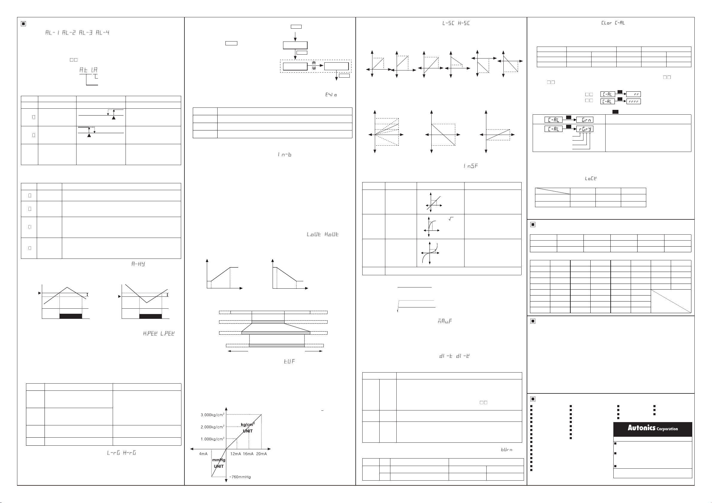
■ Alarm [ AL-1, AL-2, AL-3, AL-4]
This product has 2 or 4 alarms to operate individually when the value is too high or
low. Alarm function is set by the combination of alarm operation and alarm option.
To clear alarm, use digital input function (setting
power OFF and ON.
For the model (KN-20 W) without alarm output, these parameters are not
※
야DI-T, DI-K
as
AlRE
) or turn the
displayed.
AT !A
Alarm option
Alarm operation
Alarm operation
٧
٧
Mode Name Alarm operation Descriptions
ㅡ ㅡ
AT)_
High limit alarm
AT!
Low limit alarm
AT@
Sensor break alarm
SBa_
※
H : Alarm output hysteresis
Alarm option
٧
٧
OFF
High limt alarm
value: 800
ON
H
Low limt alarm
PV
value:200
ㅡ
℃
OFF
Option Name Descriptions
AT .A
Standard
alarm
If it is an alarm condition, alarm output is ON. Unless an alarm
condition, alarm output is OFF.
If it is an alarm condition, alarm output is ON. Before clearing
AT .B
Alarm latch
the alarm, an ON condition is latched. (Holding the alarm
output)
First alarm condition is ignored. From the second alarm
AT .C
Standby
sequence
condition, standard alarm operates.
When power is ON and it is an alarm condition, it is ignored.
From the second alarm condition, standard alarm operates.
If it is an alarm condition, it operates both alarm latch and
standby sequence.
When power is ON and it is an alarm condition, it is ignored.
From the second alarm condition, alarm latch operates.
AT .D
Alarm latch
and standby
sequence
■ Alarm output hysteresis [Program mode: ㅁA-HY]
Set the interval of ON/OFF alarm output.
The set hysteresis is applied to AL1 to AL4 and it is as below.
Ex)
※
High limit
alarm value
: 4, high limit alarm value: 800, low limit alarm value: 200
A-HY
Low limit
:4
A-HY
800
800
ON
796
OFF
alarm value
■ High/Low peak monitoring [Monitoring mode: H.PEK, L.PEK]
This function is to save high/low peak to check the invisible abnormal condition of
system at [h PEK ] or [l P E K] in monitoring mode.
When the high/low peak is out of the temperature range, it displays HHHH or LLLL.
To initialize high/low peak, press the 3, 4keys at the same time for 3 sec. at [h PE K]
or [l P EK ].
In this case, peak value is the present input value.
■ Error
Display Descriptions Troubleshooting
Flashes when measured sensor
input is lower than the temperature
LLLL
range.
Flashes when measured sensor
input is higher than the temperature
HHHH
range.
Flashes when the sensor is break
BURN
or not connected.
Flashes when there is error to SV Check set conditions and re-set it.
ERR
■ User input range [Program mode: L-RG, H-RG]
When selecting analog input, you can set the input range for your purpose. Set low
limit input value [ L-RG] and high limit input value [ H - RG] to limit the input range.
•Set conditions :
Low limit input value [ L-RG] +20%F.S. < High limit input value [ H-RG]
No alarm operation
ON
H
PV ≥ alarm temperature,
alarm is ON
PV
PV ≤ alarm temperature,
alarm is ON
℃
It will be ON when it detects
sensor disconnection.
Sensor break alarm does not
have alarm option.
200
200
ON
OFF
When input is moved within the
temperature range, it is cleared.
Check temperature sensor
connection.
204
A-HY
■ Parameter initialization
To initialize all parameter as factory
default, supply the power to the product
with pressing the
the same time and it enters initialization
parameter.
MODE
and 1 keys at
Press the
at the same time.
MODE
+
1keys
Supply the power.
CLR
MODE
NO
■ Input and transmission output extension [Program mode: ExIO]
This function is to extend analog input and 4 to 20mA transmission output to 5% or
10% range.
Mode Operation
0P
5P
10P
This parameter is displayed only for transmission output (4-20 mA) model. But it is
※
not displayed when selecting temperature sensor input.
■ Input correction [Program mode: IN-B]
This function is to correct the error occurring from a thermocouple, a RTD or analog
input out of allowable error range of this unit.
This is also available to correct error when a sensor cannot contact the subject
position by calculating the error temperature.
Variable temperature sensors have accuracy level. Because high accuracy type is
expansive, standard thermocouples are generally used.
In this case, temperature sensor may occur error. By executing this function, you can
get more accurate temperature.
When executing input correction function, you should measure the error from a sensor
accurately. If the measured error is not correct, error may be greater.
(If
InSF= TUF, IN-B
function. Refer to Two unit function.)
Ex)When measured temperature is 4 ℃ and actual temperature is 0 ℃. Set
-4, and and display value is 0 ℃.
■ Transmission output scale [Program mode : lOUT, hOUT]
For 4-20 mA current output, this function is to set the display value for 4 mA [ l O U T]
and the display value for 20 mA [h O U T].
The interval between lOUTand hOUTis 10% F.S. If it is below 10%, it is xed as 10%
of SV.
Output
20mA
4mA
:4
Relation among input range, user input range, display scale, and transmission scale
※
The below gure is the example for 4 to 20 mA.
Input range
input range
Display scale
(display value)
Transmission
output scale
■ Two Unit Function [Program mode: TUF]
When connecting a pressure sensor, compound pressure which is below atmospheric
pressure (0) is for vacuum as mmHg and which is atmospheric pressure or over it is
for positive pressure as kg/cm2.
Atmospheric pressure is 0 kg/cm2. When this unit does not display 0 kg/cm2 , you can
correct zero-point adjustment function.
When using two unit function,
L-SC
19999 range.
Outputs 4 to 20 mA within analog input range.
Outputs 3.2 to 20.8 mA for 5% out of the analog input range.
Outputs 2.4 to 21.6 mA for 10% out of the analog input range.
as atmospheric pressure input value not as input correction
Output
20mA
4mA
lOUT
User
hOUT
LLLL HHHH
parameter is displayed but you cannot set this. You can set
Display
Display
4mA 20mA
L-RG= 6 H-RG= 16
L-SC= 0 H-SC= 1000
lOUT= 100 hOUT= 900
4mA
transmission
L-SC
lOUT
transmission
is xed as -760.
hOUT
Display
20mA
Ex)When pressure range is 760.0 mmHg to
3.000 kg/cm2 , and pressure transmitter
outputs 4-20 mA, set the scale as H-SC:
3000, dP: )000
. This unit displays for
4 mA input as -76)0, and for 20 mA
input as #000.
Input
H-SC
YES
MODE
Completes
initialization.
IN-B
within 0 to
■
Display scale [Program mode: L-SC, H-SC]
For analog input, this function is to set (-19999 to 19999) for particular high/low limit
value in order to display high/low limit value of measurement input. If measurement
inputs are ‘a’ and ‘b’ and particular values are ‘A’ and ‘B’, it will display a=A, b=B as
below graphs.
Display
value
Display
value
Input
value
B
A
B
A
a b
a b
Display
value
Input
value
Display
value
b
Input
value
B
A
B
A
a b
Display
value
Input
value
a b
A
B
Display scale function is able to change display value for max./min. measured input by
setting high limit scale [
Ex) Set high/low scale value (input range is 0 to 10V)
※
• L-SC= )00
• H-SC= %00, 1)00, 1%00, `)00
Display
value
1%00
1)00
%00
0
`)00
] and low limit scale [
H-SC
• L-SC=1)00, H-SC= `)00
Display
value
1%00
1)00
Input
value
10V
`)00
] in program mode.
L-SC
• L-SC=-%00, H-SC= %00
Display
value
1%00
1)00
%00
Input
0
value
10V
-%00
0
※When changing input type, high/low scale is changed as factory default.
■ Input special function [Program mode: InSF]
When selecting analog input, this function is to display the calculated actual value by
square, root (√), or two unit function (TUF) as display value.
Parameter Functions Graph Applications
Outputs as input
value
Outputs the
rooted
as
LIN
ROOT
(√) input value
Outputs the
SQAR
squared input
value
TUF
Refer to ‘Two unit function’
※Display value and mA output value for
Display value={( ) ×(
(output value)
Input value -
H-RG
※Display value and mA output value for
Display value={( )×(
(output value)
Input value -
H-RG
L-RG
-
L-RG
-
L-RG
Display
Display
Display
L-RG
Y = AX + B
Input
Y = A( X ) + B
(X ≥ 0)
Y=0(X < 0)
Input
Y = A(X)2 + B
(X > 0)
Input
Y = -A(X)
(X < 0)
SQAR
2
H-SC-L-SC
ROOT
H-SC-L-SC
Standard characteristics.
Input for linearity.
Used for measuring ows by
pressure signal.
Used for outputting differential
pressure by ow signal.
2
+ B
:
)}+
L-SC
:
)}+
L-SC
■ Digital filter [Program mode: MAvF]
Moving average digital lter is able to stably display and output the noise from input
line and irregular signals as software.
• Filter set range : 01 to 16
(When setting as 01, digital lter function does not run.)
Display cycle is same when executing moving average digital lter.
※
■ Digital input [Program mode: DI-T, DI-K]
By digital input terminal [ DI-T] (no. 6, 7 terminals) or digital input key [ DI-K] (D.IN3
: 4+3 for 3 sec.), one of three functions executes as the below table.
Function Operaiton
When alarm is ON in RUN mode, it clears alarm forcibly. (It applies
only for alarm latch, alarm latch and standby sequence options.)
Alarm
AlRE
HOLD
ZERO
■ Alarm output for disconnecting input sensor [Program mode: BURN]
When disconnecting input sensor, you can set the status of transmission output.
Parameter
BURN
Alarm clear operates only when the value is out of the alarm value
clear
range. After clearing alarm, alarm operates its option normally.
※For the model without alarm output (KN-20 W), this parameter
is not displayed.
Display
Temporarily indicated value is stopped in order to check indicated
HOLD
value in unstable input.
Zero-
Set preset display value as 0.
point
This function is related with input correction [ IN- B]. When
adjust-
executing zero adjustment function in display value as 4, input
ment
correction value [IN- B] is set as -4 automatically.
SV Transmission output(4-20 mA) Alarm output
ON
20 mA+5% output High limit alarm ON Low limit alarm OFF
OFF
4 mA-5% output High limit alarm OFF Low limit alarm ON
Display
value
Input
value
■ Display color [Program mode: CLOR/ C-AL]
This function is to change display color for occurring error, operating alarm
automatically. User can check the status of this unit directly.
※
Color of monitoring mode, program mode is red.
RUN mode and error display color [Program mode:
٧
٧
Parameter Display color Parameter Display color
A
b
B
Input
value
SV RUN Error
RED
GRN
Alarm display color[Program mode:
٧
٧
Red Red
Green Green
This parameter is displayed only for the alarm output models (KN-22 W,
C-AL
YELO
R--G
G--R
]
]
CLOR
Yellow Yellow
Red Green
Green Red
KN24 W).
The number of set digit is same as the number of alarm output.
10V
Input
value
•
[2 alarm outputs (KN-22 W)]
[4 alarm outputs( KN-24 W)]
Set color for each alarm. It changes as R→ G → Y → R in turn.
•
Ex)
※
When alarm is cleared, or two alarms operate at the same time, the latest alarm’s color is
•
AL-4 color
AL-3 color
AL-2 color
AL-1 color
S
S
S
S
S
:Press any one among the 1, 3, 4 keys.
RUN mode color is green.
① AL-1 is ON, display is green → yellow.
② AL-2 is ON, display is yellow → red.
③ AL-3 is ON, display is red → green.
④ AL-4 is ON, display is green → red.
applied.
When error occurs [
•
HH H H, LLLL, BU RN, ERR, ERR1
] during alarm, the set color of
CLOR
is applied.
■ Lock [Program mode: LOCK]
It limits to check parameter set value and to change it.
OFF LOC1 LOC2
Program mode
Monitoring mode
●: Enable to check/set, ◐: Enable to check, disable to set, ○: Disable to check
※
In
, only
LO C2
● ◐ ○
● ● ◐
parameter displays in program mode.
LO CK
Factory default
■ Monitoring mode
Parameter Default Parameter Default Parameter Default
AL1 09(9 AL3 00)1 hPEK ---AL2 09(9 AL4 00)1 lPEK ----
■ Program mode
Parameter Default Parameter Default Parameter Default Parameter Default
IN-P aMA2 lOUT 00)0 InSF LIN ADDR 01
UNIT ?C hOUT 10)0 IN-B 0000 BAUD (6K
dUNT ?/O ExI0 5P MAuF 04 COMW EnA
L-RG 0$00 AL-1 AT!A DI-T HOLD LOCK OFF
H-RG 2)00 AL-2 AT!A DI-K HOLD
dP )0 AL-3 AT@A CLOR RED
L-SC 00)0 AL-4 AT@A C-AL RRRR
H-SC 10)0 A-HY 001 BURN ON
Caution for using
1. For connecting the power, use a crimp terminal(M3.5, min. 7.2 mm).
2. The connection of this unit should be separated from the power line and high voltage
line in order to prevent inductive noise.
3. Install a power switch or a circuit breaker to supply or cut off the power.
4. Switch or circuit breaker should be installed nearby users for convenient control.
5. Do not use this unit near the high frequency instruments (high frequency welding
machine & sewing machine, large capacity SCR controller).
6. When supplying input, if H H HH or LLLL is displayed, measured input may have
problem. Turn off the power and check the line.
7. Installation environment
It shall be used indoor.
①
Altitude max. 2,000 m
③
※
It may cause malfunction if above instructions are not followed.
Major products
Photoelectric sensors Temperature controllers
Fiber optic sensors
Door sensors SSR/Power controllers
Door side sensors Counters
Area sensors Timers
Proximity sensors Panel meters
Pressure sensors Tachometer/Pulse(Rate)meters
Rotary encoders Display units
Connectors/Sockets Sensor controllers
Switching mode power supplies
Control switches/Lamps/Buzzers
I/O Terminal Blocks & Cables
Stepper motors/drivers/motion controllers
Graphic/Logic panels
Field network devices
Laser marking system(Fiber, CO₂, Nd:YAG)
Laser welding/soldering system
Temperature/Humidity transducers
Pollution Degree 2
②
Installation category
④
Recorders Thyristor units
Indicators Pressure transmitters
Converters Temperature transmitters
Controllers
Satisable Partner For Factory Automation
HEAD QUARTERS:
116, Ungbigongdan-gil, Yangsan-si, Gyeongsangnam-do,
Korea
OVERSEAS SALES:
#402-404, Bucheon Techno Park, 655, Pyeongcheon-ro,
Wonmi-gu, Bucheon, Gyeonggi-do, Korea
TEL: 82-32-610-2730 / FAX: 82-32-329-0728
E-mail: sales@autonics.com
The proposal of a product improvement and
development: product@autonics.com
Ⅱ
http://www.autonics.com
AEP-E-0203
 Loading...