

DRW161281AC
Autonics
COUNTER / TIMER
FXY SERIES
I N S T R U C T I O N M A N U A L
-
123'-/
Thank you for choosing our Autonics product.
Please read the following safety considerations before use.
Safety Considerations
00
Please observe all safety considera ions for safe and proper product operation to avoid
※
hazards.
symbol represents cau ion due to special circumstances in which hazards may occur.
※
Failure to follow these instructions may result in serious injury or death.
Warning
Caution
Warning
1. Fail-safe device must be installed when using the unit with machinery that may cause
serious injury or substantial economic loss. (e.g. nuclear power control, medical equipment,
ships, vehicles, railways, aircraft, combustion apparatus, safety equipment, crime/disaster
prevention devices, etc.)
Failure to follow this instruction may result in re, personal injury, or economic loss.
2. Install on a device panel to use.
Failure to follow this instruction may result in electric shock or re.
3. Do not connect, repair, or inspect the unit while connected to a power source.
Failure to follow this instruction may result in electric shock or re.
4. Check ‘Connections’ before wiring.
Failure to follow this instruction may result in re.
5. Do not disassemble or modify the unit.
Failure to follow this instruction may result in electric shock or re.
Caution
1. When connecting the power/sensor input, use AWG 20(0.50mm2) cable or over, and tighten
the terminal screw with a tightening torque of 0.74 to 0.90N.m.
Failure to follow this instruction may result in re or malfunction due to contact failure.
2. Use the unit within the rated specications.
Failure to follow this instruction may result in re or product damage.
3. Use dry cloth to clean the unit, and do not use water or organic solvent.
Failure to follow this instruction may result in electric shock or re.
4. Do not use the unit in the place where ammable/explosive/corrosive gas, humidity,
direct sunlight, radiant heat, vibration, impact, or salinity may be present.
Failure to follow this instruction may result in re or explosion.
5. Keep metal chip, dust, and wire residue from owing into the unit.
Failure to follow this instruction may result in re or product damage.
Dimensions
00
-
Panel cut-out
Min. 40
1-----------------------1
Connections
00
FX Y-I4
•
□
※
(INHIBIT) PNP NPN
1 2 3 4 5 6 7
l
□□□□□□□
CP1
CP2
※
INHIBIT: In case of timer mode, this terminal is for time hold.
※
The above specications are subject to change and some models may be discontinued
without notice.
※
Be sure to follow cautions written in the instruction manual and the technical descriptions
(catalog, homepage).
Failure to follow these instructions may result in personal injury or product damage.
72 776
=
=
BlJOBSBb
36
I \
Min. 91
68
12VDC
0VDC RESET
50mA
(voltage input (PNP): connect with 12VDC, non-voltage input (NPN): connect with 0VDC)
t@1
SOURCE:
100-240VAC
50/60Hz 3.8VA
=
=
=
~
0
+0.5
+0.7
31.5
0
I
~
f231·/S6
FX6Y
I
=
RESET
(unit: mm)
30
=
rg
Bracket
4
=-;il:::::t__J
60
I I
~
12
FX Y-I2
•
□
※
(INH BIT)
PNP NPN
1 2 3 4 5 6 7
l
□□□□□□□
CP1
CP2
12VDC
0VDC RESET
50mA
9
[[]
SOURCE
6
: 24VAC 50/60Hz 2.8VA
•
24-48VDC 1 8W
•
Model
00
Model Display digit Size Output Power supply
FX4Y-I2
FX4Y-I4 100-240VAC 50/60Hz
FX6Y-I2
FX6Y-I4 100-240VAC 50/60Hz
I
Specications
00
Model Indicator FX4Y-I2 FX4Y-I4 FX6Y-I2 FX6Y-I4
Display digit 4-digit 6-digit
Character size (W×H) 8×14mm 4×8mm
Power supply
Permissible voltage range 90 to 110% of rated voltage
Power consumption
Max. counting speed of
CP1/CP2
Return time Max. 500ms
Min. signal width INHIBIT, RESET: approx. 20ms
Input method
Repeat/Set/Voltage/Temp.
error
Insulation resistance Over 100MΩ (at 500VDC megger)
External power supply Max. 12VDC
Memory retention Approx. 10 years (non-volatile memory)
Dielectric strength 2,000VAC 50/60Hz for 1 min (between all terminals and case)
Noise
immunity
Vibration
Shock
Environment
Protection structure IP40 (front part, IEC standard)
Approval
Weight
※
1: The weight includes packaging. The weight in paren hesis is for unit only.
※
Environment resistance is rated at no freezing or condensation.
Input Connection
00
Voltage input (PNP)
Solid state input (standard sensor: PNP output type sensor) Contact input
•
Sensor
(PNP output)
※
CP1, CP2 (INHIBIT), RESET input part
No-voltage input (NPN)
Solid state input (standard sensor: NPN output type sensor) Contact input
•
Sensor
(NPN output)
※
CP1, CP2 (INHIBIT), RESET input part
_________
14 5
Dot for Decimal Point / Hour. Min. Second
00
RESET
c:::::::::J
I
9999 (4-digit)
999999 (6-digit)
AC voltage ±2kV the square wave noise (pulse width 1㎲) by noise simulator
AC/DC voltage ±500V the square wave noise (pulse width 1㎲) by noise simulator
Mechanical
Malfunction
Mechanical 300m/s
Malfunction 100m/s
Ambient temp. -10 to 55℃, storage: -25 to 65
Ambient humi. 35 to 85%RH, storage: 35 to 85%RH
※
1
Counter/Timer
Brown
Black
※
Blue
D N W72×H36mm Indicator
ᜠ
50/60Hz,
24VAC
ᜡ
24-48VDC
Max. 2.8VA
(24VACᜠ 50/60Hz),
Max. 1.8W
(24-48VDCᜡ)
Selectable 1cps/30cps/2kcps/5kcps (D P switch)
Selectable voltage input (PNP) method or no-voltage input (NPN) method
[Voltage input (PNP) method]-input impedance: max. 10.8kΩ,
[No-voltage input (NPN) method]-short-circuit impedance: max. 470Ω,
Max. ±0.01% ±0.05 sec
ᜡ
±10% 50mA
0.75mm amplitude at frequency 10 to 55Hz (for 1 min) in each X, Y, Z
direction for 1 hour
0.5mm amplitude at frequency 10 to 55Hz (for 1 min) in each X, Y, Z
direction for 10 minutes
2
(approx. 30G) in each X, Y, Z direction for 3 times
2
(approx. 10G)in each X, Y, Z direction for 3 times
CE:
,'ill.
Approx. 175g (approx. 120g)
+12V
Inner
circuit
10.8kΩ
0V
Sensor
(PNP open collector output)
I
100-240VACᜠ
50/60Hz
Max. 3.8VA
(240VACᜠ 50/60Hz)
[H]: 5-30VDC
℃
Counter/Timer
Brown
Black
※
Blue
24VAC 50/60Hz, 24-48VDC
24VAC 50/60Hz, 24-48VDC
f------1
24VACᜠ 50/60Hz,
ᜡ
24-48VDC
Max. 2.8VA
(24VACᜠ 50/60Hz),
Max. 1.8W
(24-48VDCᜡ)
ᜡ
, [L]: 0-2VDC
short-circuit residual voltage: max. 1VDC,
open-circuit impedance: min. 100kΩ
•
+12V
Inner
circuit
10.8kΩ
0V
1£
※
•
Counter/Timer
Brown
Black
※
Blue
3 sec
Setting mode
Counter mode Timer mode
+12V
5.4kΩ
Inner
circuit
0V
RUN mode
Set decimal point
RESET
by front
Sensor
(NPN open collector output)
RESET
3 sec
DP
RESET
Hour, Min, Sec are not
divided with dot.
E.g.)
5959
Counter/Timer
Brown
Black
※
Blue
※
In run mode, hold the
and it enters setting mode [DP].
※
In setting mode, hold the
and it saves the setting and returns to RUN mode.
※
If there is no
setting mode, it returns to RUN mode.
CLR SET
: 59 min 59 sec
+12V
5.4kΩ
Inner
circuit
0V
RESET
key input for 60 sec when entering
c:::::::::J
RESET
Hour, Min, Sec are divided with dot.
E.g.)
,£
RESET
key for over 3 sec,
c:::::::::J
RESET
key for over 3 sec,
c:::::::::J
: 59 min 59 sec
)5(59
※
---------i
100-240VACᜠ
50/60Hz
Max. 3.8VA
(240VACᜠ 50/60Hz)
Counter/Timer
※
+12V
Inner
circuit
10 8kΩ
0V
Counting speed
: Set as 1 or 30cps
Counter/Timer
+12V
5.4kΩ
※
Inner
circuit
0V
Counting speed
: Set as 1 or 30cps
___,
DIP Switch Setting
00
2 3 4 5
1
OFF
~~~~~~[;]~[;][;]
ON
L__
ON
Up/Down mode
•
SW Function
OFF
ON
4
OFF
ON
Memory backup
SW Function
OFF
ON
8
OFF
[;J
ON
※
How to change settings
Power OFF → change settings → power ON → press
Input Operation Mode (Counter)
00
Input mode SW1 Voltage input (PNP) method No-voltage input (NPN) method
Up/
Down-A
(command
input)
Up/
Down-B
(individual
input)
Up/
Up
Down-C
mode
(phase
4
difference
OFF
input)
ON
~
Up
(adding
input)
Up/
Down-D
(command
input)
Up/
Down-E
(individual
input)
Up/
Down
Down-F
mode
(phase
4
difference
OFF
input)
[;J
ON
Down
(subtracting
input)
※
A: over min. signal width, B: over than 1/2 of min. signal width.
If the signal is smaller than these width, it may cause counting error (±1).
※
n: +Max. display value (FX4Y
6 7 8 9 10
___J
SW
2 3 4 5 6 7 8 9 0
Up mode
Down mode
Memory backup
No memory
backup
2 3
OFF
ON
2 3
OFF
ON
~
2 3
OFF
ON
2 3
OFF
[;];]
ON
2 3
OFF
ON
~
2 3
OFF
ON
~
2 3
OFF
ON
~
2 3
OFF
[;];]
ON
-I: 9999, FX6Y-I: 999999)
Time range (Timer)
Input operation mode (Counter)
Up/Down mode
Max. counting speed (Counter)
Available/Unavailable front
Memory backup
Counter/Timer mode
Input logic (NPN/PNP)
Factory default
Available/Unavailable
•
RESET
front
SW Function
OFF
7
OFF
Counter/Timer mode
•
SW Function
OFF
9
OFF
c=i
ON
ON
ON
ON
~
[;J
~
[;J
key
Unavailable front
RESET
key
c:::::::::J
Available front
RESET
key
c:::::::::J
Timer mode
Counter mode
c:::::::::J
H
CP1
L
PPP
PP
A
I I
1..........i.-1 ............
H
CP2
1:1~:I
L
I I I I I I I
Count
CP1
CP2
Count
CP1
CP2
Count
CP1
CP2
Count
CP1
CP2
Count
CP1
CP2
Count
CP1
CP2
Count
CP1
CP2
Count
CP1
CP2
Count
CP1
CP2
Count
H
L
H
L
H
L
H
L
H
L
H
L
H
L
H
L
H
L
H
L
0
H
L
H
L
0
H
L
H
L
0
H
L
H
L
0
H
L
H
L
0
3
2
2
1
0
~
1
p p p p p p
· : ·
ppo:
I I I I I I I I
3
2
2
1
0
~
QQQ
BBBB
1
0
PPP
: : :
: I :
I : I
1
0
~
:::::::::J,----
Q Q
: :
1
0
1-----
PPP
: : :
n
n-1
~
pp
23212
nn np
A A
1-::-:,~
No counting
L-.J
3
2
No counting
A A
a:
□
a:Q
2
PO
A
:2----±--i ~ :
n-2
n-2
n-3
1
L-J--}-
A
n-1
p p p p p p
' : '
pp
n-2
pp
n-2
n-2
n-3
nn
A A
--r---r-~ :
No counting
n-2
n-3
No counting
A A
n-2
tJ:
n-1 n-1
n-1
n-3
n
I I I I I I I
n-1
n-2
~
QQQ
BBBB
n
n-1
PPP
: : :
n
n-1
~
n
n-1
RESET
key
Max. counting speed
•
(counter)
SW Function
5 6
OFF
ON
~
5 6
OFF
ON
~
5 6
OFF
ON
~
5 6
OFF
[;][;]
ON
Input logic (CP1, CP2,
•
INHIBIT, RESET input)
SW Function
OFF
ON
10
OFF
[;J
ON
RESET
key or input signal (min. 20ms)
H
µµµ
CP1
PP
A
1
qq
I :
~
3
Pfl
n-2
n-2
QQ
n-2
PP
n-4
n-4
2
2
4
q
4
L
I
3
3
3
:
5
5
n-3
'
n-3n-3
n-3
n-5
n-5
I I
H
CP2
L
:
':
Count
1
0
~
H
CP1
L
µµp
H
CP2
L
: : :
Count
1
0
~
H
CP1
L
444
BB
BB
ttt+-1
H
CP2
L
□:
□•
Count
1
0
~
H
CP1
ODO
L
: I :
H
CP2
L
: : :
: I I
Count
1
~
0
H
CP1
L
H
CP2
L
□□
I I I I I
Count
I I
1
0
µf-----'·
H
CP1
µpµ
L
I I I
H
: I I I I I :
CP2
L
n
I I I I I I I
n-1
n-2
Count
~
0
H
CP1
uu
L
H
CP2
: : :
L
I I I I I I I I
n
n-1
Count
n-2
~
0
H
CP1
L
BBBB
H
CP2
L
n
n-1
Count
0
H
CP1
LILILI
L
I I I I I
I I I -,--r-- -,--r- I
H
CP2
I I I c::::::::J I I
L
n
n-1
n-2
Count
~
0
H
CP1
L
H
CP2
L
□□LJ□LJ□□
n
n-1
Count
0
1cps
30cps
2kcps
5kcps
PNP
(voltage input)
NPN
(no-voltage input)
※
CP: Clock Pulse
µµ
µµ
A
A
1....,....,.....
I~
t::;::::::::::.~.
3
212
2
PPP
ppµ:
232
1
1
µµ
I I I I I I
□,
2
2
DODO
U
n-2
--i-r- --i-r-
44
.□•□ □•
3
212
DO
A A
=t_____r+
No counting
L-.J:
3
No counting
A A
3
~
2
LILI
LILI
A A
=tt_b-tt
n-1
n-2
n-2
n-3
LI
00
uob:
n-1
n-1
n-2
n-3
n-1
n-2
n-3
Ou
LILI
A A
No count ng
n-3
No counting
I I
A
A
n-2
n-3
DO
~
n-2
n-4
n-4
2
□.
4
□
4
I
:
n-2
Detaching Case
00
※
Turn OFF the power before detaching the case.
Press the both levers and pull them from the front to
detach the case and the terminal.
Time Range (Timer)
00
SW 4-digit 6-digit
1 2 3
OFF
ON
OFF
ON
OFF
ON
OFF
ON
99.99sec 99999 9sec
1·1·1·1
1 2 3
999.9sec 999999sec
1.1■1■1
1 2 3
9999sec
1·1.1·1
1 2 3
99min 59sec
1.1.1
■
1
99min
59 99sec
999min
59 9sec
SW 4-digit 6-digit
1 2 3
OFF
ON
OFF
ON
OFF
ON
OFF
ON
999 9min 99999.9min
1·1·1.1
1 2 3
99hour
59min
1.1·1.1
1 2 3
999 9hour
1·1.1.1
1 2 3
9999hour 99999.9hour
1.1.1.1
Counting & Time Operation
Counting operation
Input mode: Up
RESET
ri
+ Max. display value
0
n
Vldv
Input mode: Up/Down-A, B, C Input mode: Up/Down-D, E, F
I
:
3
3
+ Max. display value
- Max. display value
RESET
0
~
Time operation
Up mode
RESET
3
+ Max. display value
INHIBIT
0
:
:
5
r-.i
Cautions during Use
~
1. Follow instructions in ‘Cautions during Use’. Otherwise, It may cause unexpected accidents.
2. 24-48VDC, 24VAC power supply should be insulated and limited voltage/current or Class 2,
SELV power supply device.
3. Use the product, 0.1 sec after supplying power.
5
4. When supplying or turning off he power, use a switch or etc. to avoid chattering.
5. Install a power switch or circuit breaker in the easily accessible place for supplying or
disconnecting the power.
6. In case of contact input, set count speed to low speed mode (1cps or 30cps) to operate.
If set to high speed mode (2kcps or 5kcps), counting error occurs due to chattering.
7. Keep away from high voltage lines or power lines to prevent induc ive noise.
n-3
n-3
n-3
n-5
n-5
In case installing power line and input signal line closely, use line lter or varistor at power
line and shielded wire at input signal line.
Do not use near he equipment which generates strong magne ic force or high frequency
noise.
8. This product may be used in he following environments.
Indoors (in
①
Altitude max. 2,000m
②
Pollu ion degree 2
③
Installation category II
④
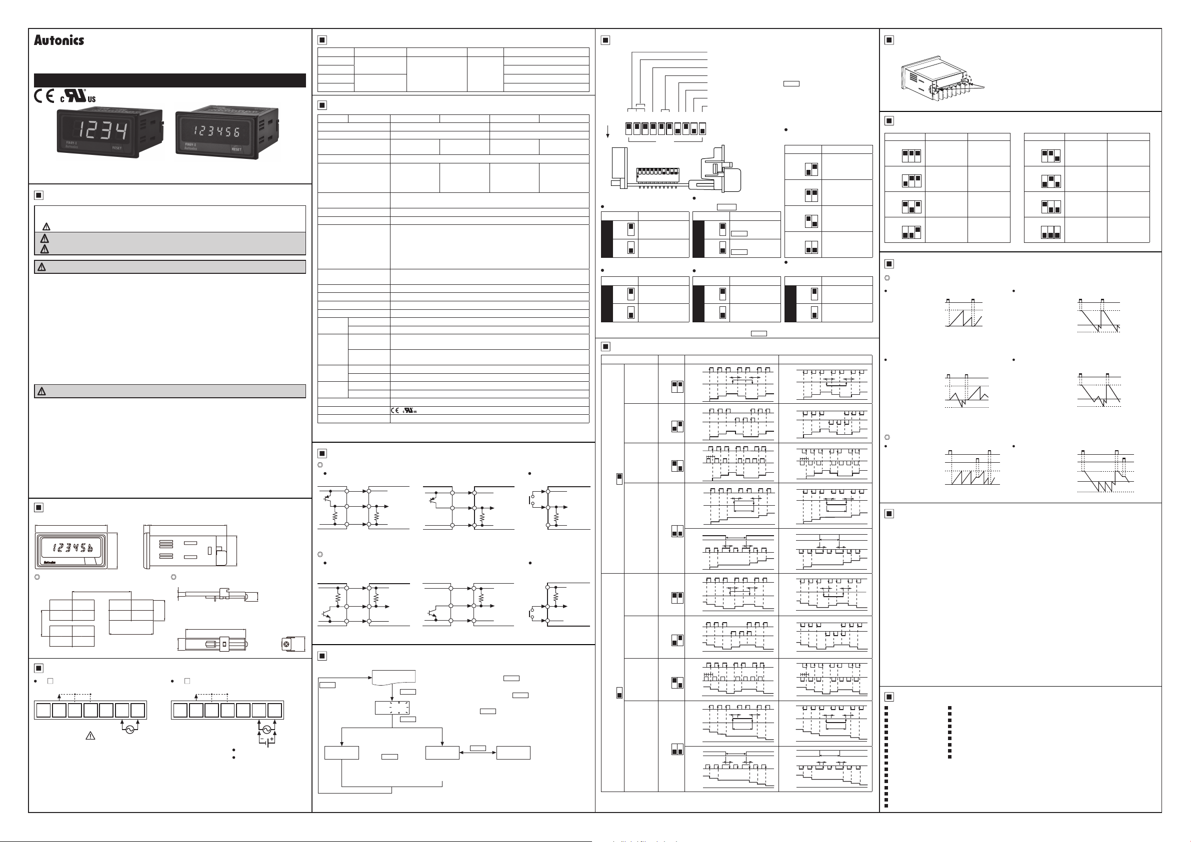
Major Products
00
Photoelectric Sensors Temperature Controllers
Fiber Optic Sensors Temperature/Humidity Transducers
Door Sensors SSR/Power Controllers
Door Side Sensors Counters
Area Sensors Timers
Proximity Sensors Panel Meters
Pressure Sensors Tachometer/Pulse (Rate) Meters
Rotary Encoders Display Units
Connector/Sockets Sensor Controllers
Switching Mode Power Supplies
Control Switches/Lamps/Buzzers
I/O Terminal Blocks & Cables
Stepper Motors/Drivers/Motion Controllers
Graphic/Logic Panels
Field Network Devices
Laser Marking System (Fiber, Co₂, Nd: YAG)
Laser Welding/Cutting System
he environment condi ion rated in ‘Specications’)
■
■
■
■
■
■
■
■
■
Input mode: Down
+ Max. display value
- Max. display value
+ Max. display value
- Max. display value
Down mode
+ Max. display value
- Max. display value
RESET
RESET
RESET
INH BIT
0
n
0
0
99hour
59min
59sec
9999hour
59min
_n
DRW161281AC
 Loading...