

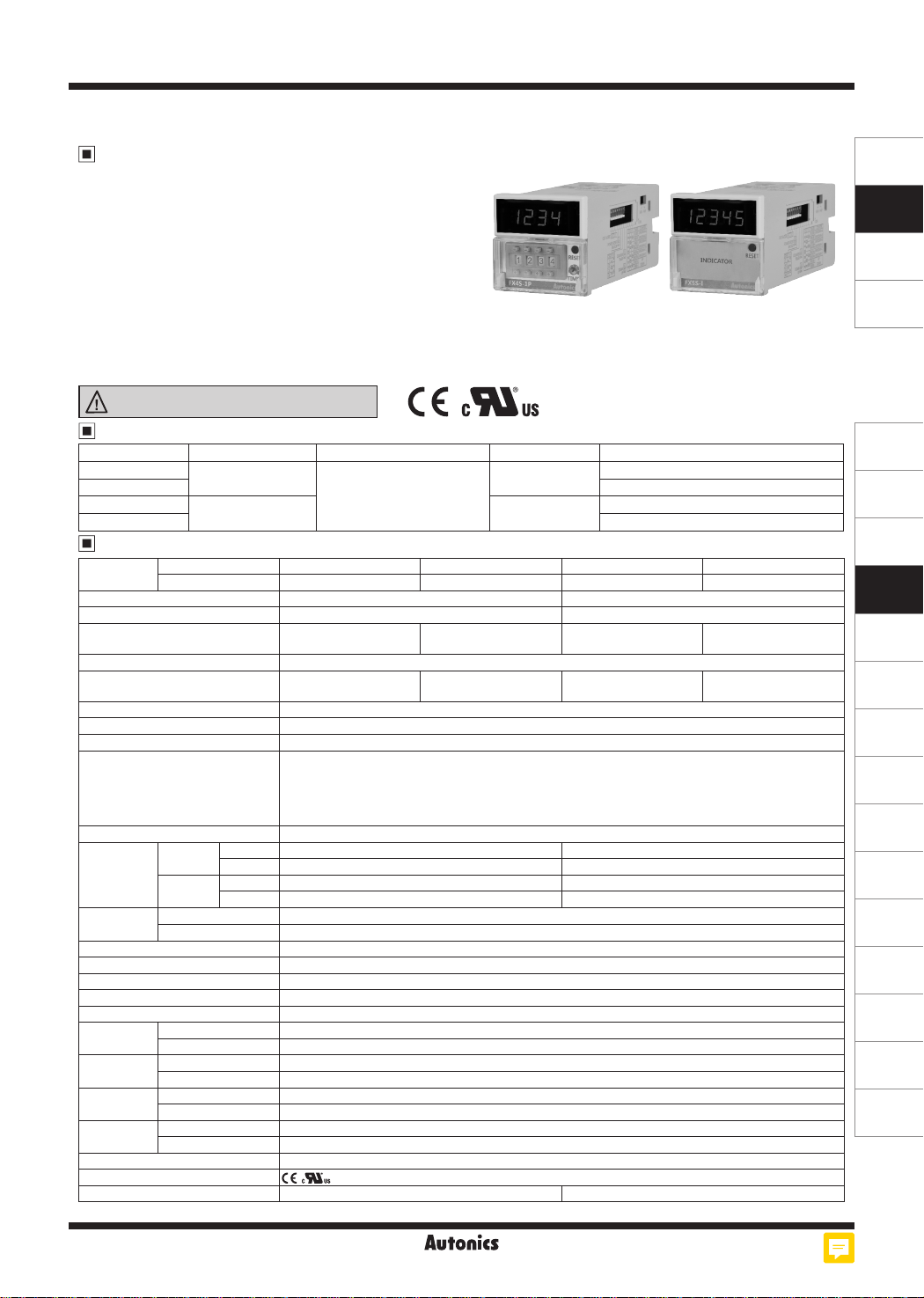
FXS Series
DIN W48×H48mm Compact Counter/Timer
Features
● Counting speed: 1cps / 30cps / 2kcps / 5kcps
● Selectable voltage input (PNP) or no-voltage input (NPN)
● Input mode: Up, Down, Up/Down
● Dot for Decimal Point / Hour. Min. Second by RESET key
● Wide range of input power supply
: 100-240VAC 50/60Hz, 24VAC 50/60Hz, 24-48VDC universal
● Selectable Counter/Timer by internal DIP switch
● [Counter]
20 input modes/18 output modes
● [Timer]
16 output modes
Various time setting range - 5-digit model: 0.01 sec to 9999.9 hour /
4-digit model: 0.01 sec to 9999 hour
● Output: Indicator, 1-stage setting
Please read “Safety Considerations”
in the instruction manual before using.
Models
Model Display digit Size Output Power supply
FX4S-1P2
FX4S-1P4 100-240VAC 50/60Hz
FX5S-I2
FX5S-I4 100-240VAC 50/60Hz
9999 (4-digit)
1-stage setting
DIN W48×H48mm
99999 (5-digit) Indicator
Specications
Model
1-stage setting FX4S-1P2 FX4S-1P4
Indicator
- -
Display digit 4-digit 5-digit
Character size (W×H) 3.8×7.6mm 4×8mm
24VAC
50/60Hz,
Power supply
ᜠ
24-48VDCᜡ
Permissible voltage range 90 to 110% of rated voltage
Power consump ion
AC: Max. 3.5VA
DC: Max. 2.3W
Max. counting speed of CP1/CP2 Selectable 1cps / 30cps / 2kcps / 5kcps (DIP switch)
Return time Max. 500ms
Min. signal width INHIBIT, RESET input: approx. 20ms
Selectable voltage input (PNP) method or no-voltage input (NPN) method
[Voltage input (PNP) method]-input impedance: max. 10.8kΩ, [H]: 5-30VDCᜡ, [L]: 0-2VDC
Input method
[No-voltage input (NPN) method]-short-circuit impedance: max. 470Ω,
open-circuit impedance: min. 100kΩ
One-shot output time 0.05 to 5 sec
Control
output
Contact
Solid
state
Relay
life cycle
Mechanical Min. 5,000,000 operations
Electrical Min. 100,000 operations (250VAC 3A resistive load)
Repeat/Set/Voltage/Temperature error
Type Instantaneous SPDT (1c)
Capacity 250VACᜠ 3A, 30VDCᜡ 3A resistive load
Type NPN open collector: 1
Capacity Max. 30VDCᜡ, 100mA
Max. ±0.01% ±0.05 sec
Insulation resistance Over 100MΩ (at 500VDC megger)
External power supply Max. 12VDCᜡ ±10% 50mA
Memory reten ion Approx. 10 years (non-volatile memory)
Dielectric streng h 2,000VAC 50/60Hz for 1 min (between all terminals and case)
Noise
immunity
Vibra ion
Shock
Environment
AC voltage ±2kV the square wave noise (pulse width 1㎲) by the noise simulator
AC/DC voltage ±500V the square wave noise (pulse width 1㎲) by the noise simulator
Mechanical 0.75mm amplitude at frequency 10 to 55Hz (for 1 min) in each X, Y, Z direction for 1 hour
Malfunction 0.5mm amplitude at frequency 10 to 55Hz (for 1 min) in each X, Y, Z direction for 10 min
Mechanical 300m/s
Malfunc ion 100m/s
Ambient temperature -10 to 55
2
(approx. 30G) in each X, Y, Z direction for 3 times
2
(approx. 10G) in each X, Y, Z direction for 3 times
, storage: -25 to 65
℃
Ambient humidity 35 to 85%RH, storage: 35 to 85%RH
Protection structure IP20 (front part, IEC standard)
Approval
※
1
Weight
※
1: The weight includes packaging. The weight in parenthesis is for unit only. ※Environment resistance is rated at no freezing or condensation.
(€
c'Alus
Approx. 171g (approx. 110g) Approx. 156g (approx. 95g)
I I
I I
100-240VACᜠ 50/60Hz
I I
Max. 4.6VA
I I
short-circuit residual voltage: max. 1VDC,
℃
Autonics
24VAC 50/60Hz, 24-48VDC
24VAC 50/60Hz, 24-48VDC
- FX5S-I2 FX5S-I4
24VACᜠ 50/60Hz,
24-48VDCᜡ
AC: Max. 3VA
DC: Max. 1 8W
100-240VACᜠ 50/60Hz
Max. 3.8VA
-
-
-
-
M-7
SENSORS
CONTROLLERS
MOTION DEVICES
SOFTWARE
(J)
Temperature
Controllers
(K)
SSRs
(L)
Power
Controllers
(M)
Counters
(N)
Timers
(O)
Digital
Panel Meters
(P)
Indicators
(Q)
Converters
(R)
Digital
Display Units
(S)
Sensor
Controllers
(T)
Switching
Mode Power
Supplies
(U)
Recorders
(V)
HMIs
(W)
Panel PC
(X)
Field Network
Devices
FXS Series
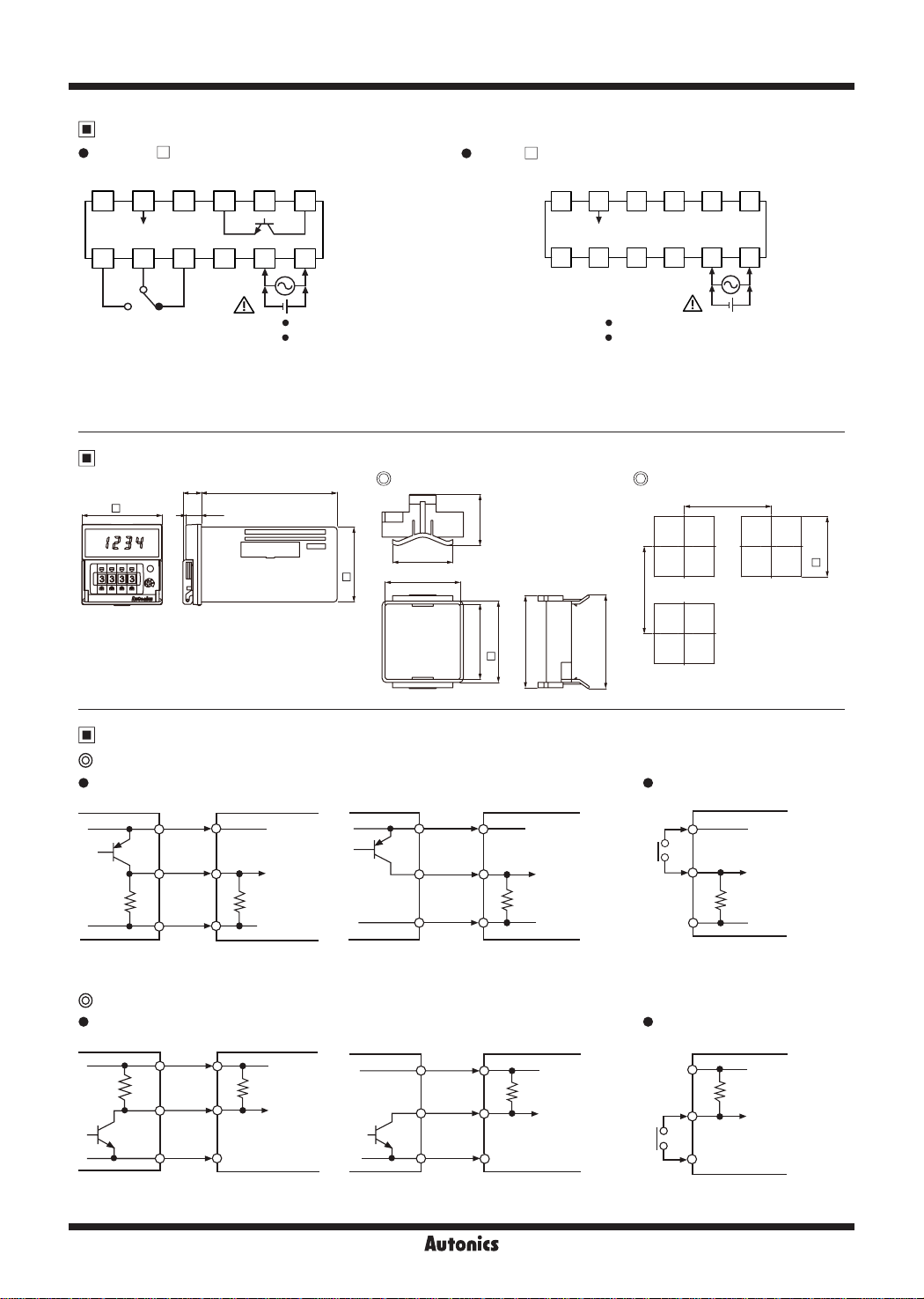
Connections
FX4S-1P
•
CP1
1728394 5 6
□
12VDC
50mA
(INHIBIT)
0VCP2 RESET
10
SOLID STATE OUT:
30VDC 100mA
11
12
FX5S-I
•
□
CP1
12VDC
50mA
(INHIBIT)
0VCP2 RESET
1728394 5 6
121110
※
1
- +
CONTACT:
250VAC 3A, 30VDC 3A
RESISTIVE LOAD
※
1: AC voltage: 100-240VAC 50/60Hz 4.6VA/3.8VA
AC/DC voltage: 24VAC 50/60Hz 3.5VA/3VA, 24-48VDC 2.3W/1.8W
※
INHIBIT: In case of timer mode, this terminal is for time hold.
(voltage input (PNP): connect with 12VDC, no-voltage input (NPN): connect with 0VDC)
SOURCE:
100-240VAC 50/60Hz 4.6VA
•
24VAC 50/60Hz 3.5VA
•
24-48VDC 2.3W
SOURCE:
Dimensions
(Q)
11.1 81.2
48
9.3
Bracket Panel cut-out
30.5
44.8
36
44.9
45
48.6
55
56
Input Connection
Voltage input (PNP)
Solid state input (standard sensor: PNP output type sensor)
•
Sensor SensorCounter/Timer Counter/Timer
Brown
+12V
Brown
+12V
- +
100-240VAC 50/60Hz 3.8VA
24VAC 50/60Hz 3VA
24-48VDC 1.8W
(Q)
Min. 65
Min. 65
Contact input
•
Counter/Timer
※
1
+12V
(unit: mm)
+0.6
0
45
※
Black
Blue
(PNP output)
※
CP1, CP2 (INHIBIT), RESET input part
@
No-voltage input (NPN)
Solid state input (standard sensor: NPN output type sensor)
•
Sensor
(NPN output)
※
CP1, CP2 (INHIBIT), RESET input part
Brown
Black
Blue
※
Inner
circuit
10.8kΩ
0V
Counter/Timer
+12V
5.4kΩ
Inner
circuit
0V
(PNP open collector output)
Sensor
(NPN open collector output)
M-74
※
Black
Blue
Brown
※
Black
Blue
Autonics
Inner
circuit
10.8kΩ
0V
Counter/Timer
+12V
kΩ
5.4
Inner
circuit
0V
※
※
Counting speed: Set as 1 or 30cps
Contact input
•
※
※
Counting speed: Set as 1 or 30cps
Inner
circuit
10.8kΩ
0V
Counter/Timer
+12V
5.4
kΩ
Inner
circuit
0V
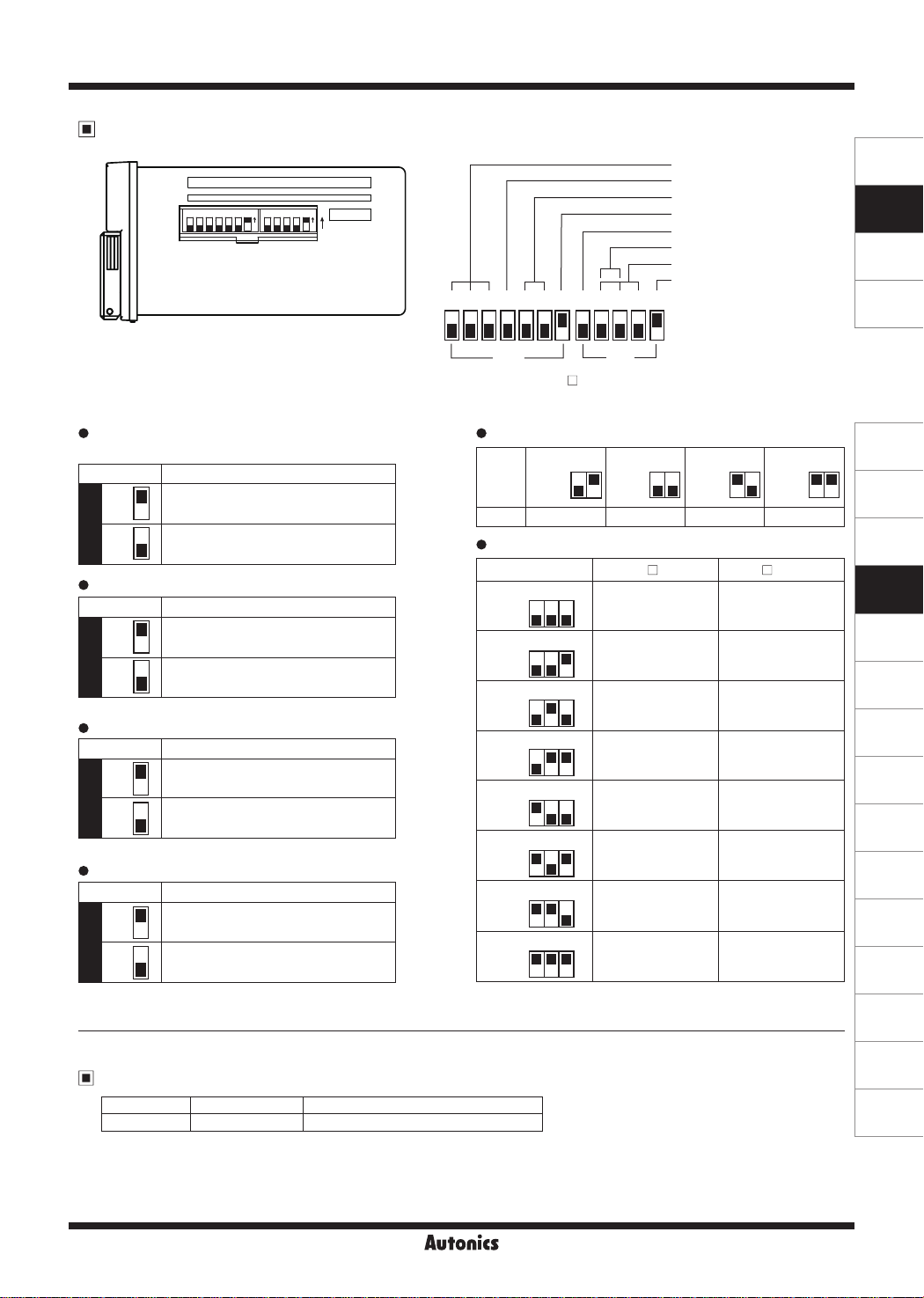
DIP Switch Setting
543214321 5 6 7
NO NO
m
lo
Up/Down Counter/Timer
Output operation mode
Memory backup
Max. counting speed
ON
※
1
7 6 5 4 3 2 1 5 4 3 2 1
ON
OFF
SW2
※
1: Indicator model (FXS5-
for output operation mode setting.
SW1
) does not have no. 5, 6, 7 of SW2.
□
Counter/Timer
Up/Down mode
Input operation mode (counter)
Time range (timer)
Input logic (NPN/PNP)
Factory default
SENSORS
CONTROLLERS
MOTION DEVICES
SOFTWARE
Input logic
• •
(CP1, CP2, INHIBIT, RESET input)
SW1 Function
ON
OFF
1
OFF
Up/Down mode
•
SW1 Function
OFF
5
OFF
Counter/Timer
•
SW2 Function
OFF
1
OFF
Memory backup
•
SW2 Function
OFF
4
OFF
NPN (No-voltage input)
ON
PNP (voltage input)
~I
ON
Down mode
ON
Up mode
~I
ON
Counter mode
ON
Timer mode
~I
ON
No memory backup
ON
Memory backup
~I
I
I
I
I
SW2
I I
Function
•
SW1 FX4S-1P
Max. counting speed
3 2
ON
OFF
~1 ~1 ~1 ~1
1cps 30cps 2kcps 5kcps
Time range (timer)
4 3 2
ON
OFF
1.1.1.1
4 3 2
ON
1.1.1
OFF
4 3 2
ON
OFF
1.1
4 3 2
ON
1.1
OFF
4 3 2
ON
OFF
1■1.1.1
4 3 2
ON
1■1.1
OFF
4 3 2
ON
1■1■1.1
OFF
4 3 2
ON
1■1■1■1
OFF
99.99 sec 9999.9 sec
999.9 sec 99999 sec
■
1
9999 sec
■
1.1
99 min
59 sec
■1■
1
999.9 min 9999.9 min
99 hour
59 min
■
1
999.9 hour
9999 hour 9999.9 hour
3 2
ON
OFF
□ □
ON
OFF
3 2
FX5S-I
9 min
59.99 sec
99 min
59.9 sec
9 hour
59 min
59 sec
999 hour
59 min
ON
OFF
3 2
(J)
Temperature
Controllers
(K)
SSRs
>-------
(L)
Power
Controllers
(M)
Counters
(N)
Timers
(O)
Digital
Panel Meters
(P)
Indicators
(Q)
Converters
(R)
Digital
Display Units
(S)
Sensor
Controllers
(T)
Switching
Mode Power
Supplies
(U)
Recorders
Error Display and Output Operation
Error Display Error description Troubleshooting
ERR0
Setting value is 0. Change the setting value anything but 0.
When error occurs, the output turns OFF.
※
Indicator model does not have error display function.
※
Autonics
M-75
(V)
HMIs
(W)
Panel PC
(X)
Field Network
Devices

FXS Series
Dot for Decimal Point / Hour. Min. Second
RESET
3sec
Counter mode Timer mode
----
※
Run mode: hold the
※
Setting mode: hold the
Changing the decimal point
•
4-digit:
5-digit:
※
It returns to RUN mode if no
Counting & Time Operation for Indicator (FX5S-I )
~
@
Counting operation
Input mode: Up
•
RESET
display value
If there is no
----
rl
----- -----
ci
+Max.
RUN mode
Set decimal point
RESET
by front
RESET
key for over 3 sec, and it enters setting mode [DP].
C=:J
RESET
key for over 3 sec, and it saves the setting and returns to RUN mode.
C=:J
RESET
C=:J
RESET
Fl
RESET
Fl
RESET
C=:J
RESET
3 sec
DP
Setting mode
RESET
CLR SET
Hour/Min/Sec are not
divided wi h dot.
5959
E.g.)
key input for 60 sec when entering setting mode, it returns to RUN mode.
----
RESET
Fl
RESET
Fl
key or digital switch is applied for 60 sec in decimal point setting status.
RESET
: 59min 59sec
----
RESET
Fl
RESET
Fl
•
display value
Hour/Min/Sec are
divided with dot.
)5(59
E.g.)
----
Input mode: Down
RESET
+Max.
: 59min 59sec
RESET
6
RESET RESET
c=i
I
□
~
---------------
• I
~
B
0
0
Input mode: Up/Down-A, B, C Input mode: Up/Down-D, E, F
•
RESET
+Max.
display value
display value
@
Time operation
Up mode Down mode
•
display value
··~···············~·······················
: : : :
0
-Max.
RESET
INHIBIT
□
+Max.
n
..
---·r/VlYLiv1
0
M-76
Autonics
-Max.
display value
•
RESET
+Max.
display value
-Max.
display value
•
RESET
INHIBIT
+Max.
display value
-Max.
display value
0
0

Up/Down Counter/Timer
Input Operation Mode (counter)
Input mode SW1 Voltage input (PNP) method No-voltage input (NPN) method
H
4 3
4 3
CP1
CP2
Count
CP1
CP2
Count
CP1
CP2
I
Count
CP1
CP2
Count
CP1
CP2
Count
CP1
CP2
Count
CP1
34
CP2
Count
CP1
CP2
Count
CP1
CP2
Count
CP1
CP2
Count
Up/Down-A
(command input)
Up/Down-B
(individual input)
Up
Up/Down-C
mode
(phase
5
dierence input)
ON
n
OFF
~
~----+--~-----===-==============------+-------====·=============----j
Up
(adding input)
Up/Down-D
(command input)
Up/Down-E
(individual input)
Down
Up/Down-F
mode
(phase
5
dierence input)
ON
OFF
~
f------+---+-----------i-------------,
Down
(subtracting
input)
※
: over min. signal wid h, B: over than 1/2 of min. input signal width. If the signal is smaller than these wid h, it may cause counting error (±1).
A
ON
OFF
ON
[l]
OFF
ON
OFF
ON
OFF
ON
OFF
~
ON
OFF
ON
OFF
ON
OFF
4 3
4 3
4 3
I
4 3
4 3
[l]
PPP
L
: : :
H
I : :
L
1 1
0
~
H
fl fl fl fl fl fl
L
H
: : :
L
1
0
~
H
qqqppqq
L
BB BB
Htti : : : : : : I I I I I I I
H
□'□'□:
L
, , , , , ,
1
~
0
H
PPP
L
I I I
H
: I :
L
I I I I I I :
I I I I+-------------
1
~t-'
0
H
L
H
L
99°
: :
1
r::::::::',---'
0
H
fl fl fl
L
: : :
H
: I I
L
I I I
I I I I I I
n
n-1
n-2 n-2
0
H
PPP PPP
L
H
: : :
L
n
n-1
n-2
~
0
H
L
BB BB
H
L
n
n-1
0
H
PPP
L
: :
H
: I I
L
I : I
n
n-1
~
0
H
L
H
q q
L
n
n-1
~
0
PP PP
A A
----i-----+-: ----i-----+-
c::::::::::::J
3 3
2 2
ppb:
3
2 2 2
2 2
2
+,._
-----'
1 1
:□'□
oo
A A
No counting
3
-4-+
0
999
fl
fl fl fl
I-..-+ :
n-1
n-2
□'□:
1
-..-+
3
~
I I
3
~
r::::::J
-----'·
No counting
A A
2
A A
----i-----+-
t::t:::::t:i
n-3 n-3
ppb:
n-1 n-1
n-2
n-3 n-3
n-3
oo
A A
:~
r::::::J
No counting
L-..J
n-3
No counting
A A
n-2
n-1
-..-+:
-4--,.-
n q q
n-3
n-2 n-2
n-2
+,._
on
: :
2
2
PP
I :
~
4
4
:
n-2
n-2
PP
I I
I :
n-4
n-4
:
n-3
:
3
3
I
5
5
n-5
n-5
H
CP1
CP2
Count
CP1
CP2
Count
Count
CP1
CP2
Count
CP1
CP2
Count
CP1
CP2
Count
CP1
CP2
Count
CP1
CP2
Count
CP1
CP2
Count
CP1
CP2
Count
oµµ
L
I:
H
I I I
L
I I I I I I
1 1
0
H
µµµ
L
H
: : :
L
: I I I I I
1 1 1
0
H
CP1
L
L..f
L..f L..f
BB BB
t-ttti1111
H
CP2
□:□
L
1 1
~
0
H
µµµLIUµµ
L
H
H
H
H
H
H
L
H
L
0
I : --tot-i+-
I I I :c_____,J- I I
L
: : :
1
L--W
0
L
L..fL..fLJOq[f
L
' :
1
b-;-'
0
µµµ
L
,,,~~'
:::~~:
I I I I I
L
n
n-1
n-2 n-2
0
µµµ µµµ
' ' '
: : :
I I I I I I I I
n
n-1 n-1 n-1
H
L..f L..f
L
BB BB
t-ttti1•,1
H
□:□:□:
L
n
n-1
~
0
H
µoµ
L
: :
H
I I I
L
n
n-1
n-2
~
0
H
L
H
44LJDL...f44
L
n
n-1
~
0
※
CP: Clock Pulse
µµ µµ
A A
:----i-----+--1~:
~~
3 3
2 2 2
µpµ
uµO:
3 3
2 2 2
µµ
L..fL..f
:u:
:u:u
3 3
2 2
2
No counting
I I
A A
-----'
A A
n-3
LI
n-3
L..f
n-2
n-3 n-3
~
L____j-
No counting
I I
A A
--1-t.-
n-2
u:u:
A A
--tt:::±
No counting
L-.J:
3
3
~
2
µµ µµ
n-1
n-2
h'
p'""': :
n-2n-2 n-2
µµ
L..fL..f
I I I I
:□:□
□:□:
n-1
n-2
00
A A
No counting
µµ
----i------+-
n-3
~
n-3
~
I I
SENSORS
I
:
II
2
:
:
5
4
[f
5
4
n-3
I
n-3
ii
n-2
:
n-4
n-5
n-4
n-5
CONTROLLERS
MOTION DEVICES
SOFTWARE
(J)
Temperature
Controllers
(K)
SSRs
(L)
Power
Controllers
(M)
Counters
(N)
Timers
(O)
Digital
Panel Meters
(P)
Indicators
(Q)
Converters
(R)
Digital
Display Units
(S)
Sensor
Controllers
(T)
Switching
Mode Power
Supplies
(U)
Recorders
(V)
HMIs
(W)
Panel PC
(X)
Field Network
Devices
Autonics
M-77

FXS Series
Output Operation Mode
5
ON
Output mode
(SW2)
F
7 6 5
ON
OFF
N
7 6 5
ON
OFF
C
7 6 5
ON
OFF
R
7 6 5
ON
OFF
K
7 6 5
ON
OFF
P
7 6 5
ON
OFF
Up, Up/Down-A, B, C Down, Up/Down-D, E, F
RESET
Setting
0
OUT
RESET
Setting
0
OUT
RESET
Setting
0
OUT
RESET
Setting
---~-
0
OUT
RESET
Setting
0
OUT
RESET
Setting
0
OUT
Up mode
OFF
---
-----
1 I I
I I I I
I I I I
• • •
-----
----
RESET
Setting
OUT
RESET
Setting
OUT
RESET
Setting
OUT
RESET
Setting
OUT
RESET
Setting
OUT
RESET
Setting
OUT
0
0
-~----
0
0
0
0
ON
OFF
q
5
Down mode
•••
Self-holding (hold) outputOne-shot output (0 05 to 5 sec)
n-
Operation
After count-up, counting display
value increases or decreases un il
reset signal input is applied and
self-holding output is maintained.
After count-up, counting display
value and self-holding output are
maintained until reset signal input is
applied.
When count-up, counting display
value is reset and it counts
simultaneously.
After count-up, counting display
value is reset after one-shot output
time and it counts simultaneously.
After count-up, counting display
value increases or decreases un il
reset signal input is applied.
After count-up, counting display
value is maintained while output
is ON. Counting value is internally
reset and it counts simultaneously.
Q
7 6 5
ON
OFF
S Up Down
Counter mode
7 6 5
ON
OFF
S
Timer mode
7 6 5
ON
OFF
※
Set one-shot output time by front TIME volume switch.
RESET
Setting
0
OUT
RESET
n n n
Setting
---0-0-~--
~
0
OUT
Up/Down-A, B, C Up/Down-D, E, F
RESET
Setting
0
OUT
RESET
Setting
0
OUT
~
h h
:/
M-78
RESET
Setting
0
OUT
RESET
Setting
0
OUT
RESET
Setting
0
OUT
RESET
Setting
-~-
0
OUT
Autonics
H
t:::J
After count-up, counting display
value increases or decreases
during one-shot output time.
Up, Up/Down-A, B, C input mode
:
Output maintains ON when counting
display value is larger or equal than
setting value.
Down, Up/Down-D, E, F input mode
:
Output maintains ON when counting
display value is smaller or equal
than setting value.
Output turns OFF→ON→OFF
repeatedly (icker).

Up/Down Counter/Timer
Proper Usage
~
Follow instructions in ‘Proper Usage’. Otherwise, it may cause unexpected accidents.
•
24-48VDC, 24VAC power supply should be insulated and limited voltage/current or Class 2, SELV power supply device.
•
Use the product, 0.1 sec after supplying power.
•
When supplying or turning o the power, use a switch or etc. to avoid chattering.
•
Install a power switch or circuit breaker in the easily accessible place for supplying or disconnecting the power.
•
In case of contact input, set count speed to low speed mode (1cps or 30cps) to operate.
•
If set to high speed mode (2kcps or 5kcps), counting error occurs due to chattering.
Keep away from high voltage lines or power lines to prevent inductive noise.
•
In case installing power line and input signal line closely, use line lter or varistor at power line and shielded wire at input
signal line.
Do not use near the equipment which generates strong magnetic force or high frequency noise.
This product may be used in the following environments.
•
Indoors (in the environment condition rated in ‘Specications’)
①
Altitude max. 2,000m
②
Pollution degree 2
③
Installation category II
④
SENSORS
CONTROLLERS
MOTION DEVICES
SOFTWARE
(J)
Temperature
Controllers
(K)
SSRs
(L)
Power
Controllers
(M)
Counters
(N)
Timers
(O)
Digital
Panel Meters
(P)
Indicators
(Q)
Converters
(R)
Digital
Display Units
(S)
Sensor
Controllers
(T)
Switching
Mode Power
Supplies
(U)
Recorders
(V)
HMIs
(W)
Panel PC
Autonics
M-79
(X)
Field Network
Devices
 Loading...