

ENP Series
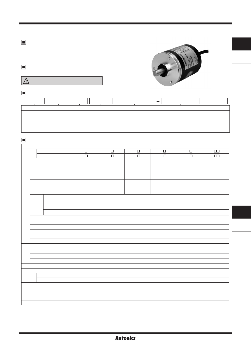
Shaft Type Ø60mm Single-turn Absolute Rotary Encoder
Features
00
● Allows to measure absolute variable angle with BCD code
● Strong against external impact
● Memorizing the absolute position when power is cut o
Applications
00
Precision numerical control machine for industrial plant
Please read “Safety Considerations”
in the instruction manual before using.
Ordering Information
00
ENP
I
Series Output code Output Power supply Revolution direction Pulses/revolution Control output
60mm
Ø
shaft type
( shaft diameter
: Ø10mm)
Specifications
00
Item Shaft Type Ø60mm Single-turn Absolute Rotary Encoder
Model
Resolution
Vibration 1.5mm amplitude at frequency of 10 to 55Hz (for 1 min) in each X, Y, Z direction for 2 hours
Shock Approx. max. 75G
Environment
Protection structure IP50 (IEC standard)
Cable
Accessory Mounting bracket, coupling
Weight
※
※
the resolution.
※
※
PNP open collector output
I
NPN open collector output
I
※
1
Output phase
Output of phase
dierences
Control
output
Response
time
(rise/fall)
Max. response frequency 20kHz
Electrical specication
Power supply • 5VDCᜡ ±5% (ripple P-P: max. 5%) • 12-24VDCᜡ ±5% (ripple P-P: max. 5%)
Current consumption Max. 100mA (disconnection of the load)
Insulation resistance Over 100MΩ (at 500VDC megger between all terminals and case)
Dielectric strength
Connection Axial cable type
Starting toque Max. 500gf.cm (0.05N·m)
Moment of inertia Max. 300g.cm
Shaft loading Radial: max. 10kgf, Thrust: max. 2 5kgf
Mechanical
Mechanical revolution
specication
Ambient temperature
I
Ambient humidity
I
※
3
1: Not indicated resolutions are customizable.
2: Make sure that max. response revolution should be lower than or equal to max. allowable revolution when selecting
Resolution
3: The weight includes packaging. The weight in parenthesis is for unit only.
Environment resistance is rated at no freezing or condensation.
1
1-1
BCD code
PNP open collector output
NPN open collector output
PNP open collector output
NPN open collector output
[Max. response revolution (rpm)=
1 1 R
I
0: Nega ive
logic
1: Positive
logic
ENP-111 -006-P ENP-111 -008-P ENP-111 -012-P ENP-111 -016-P ENP-111 -024-P ENP-11 -360-P
ENP-101 -006-N ENP-101 -008-N ENP-101 -012-N ENP-101 -016-N ENP-101 -024-N ENP-10 -360-N
6-division 8-division 12-division 16-division 24-division 360-division
TP (timing pulse)
: 2-bit
TS (signal pulse)
: 4-bit (BCD, EP)
TP1: 53° ±30'
TP2: 15° ±30'
P: 60° ±30'
TS: 56° ±30'
Output voltage: min. (power supply-1.5V)VDCᜡ, Load current: max. 32mA
Load current: max. 32mA, residual voltage: max. 1VDCᜡ
Ton=800ns, To=max. 800ns (cable length: 1m, I sink=32mA)
Ton=800ns, To=max. 800ns (cable length: 1m, I sink=32mA)
750VAC 50/60Hz for 1 minute (between all terminals and case)
※
2
3,600rpm
-10 to 70℃, storage: -25 to 85℃
35 to 85%RH, storage: 35 to 90%RH
Ø8mm, 12-wire, 1m, double shield cable
(AWG24, core diameter: 0.08mm, number of cores: 40, insulator diameter: Ø1mm)
Approx. 478g (approx. 400g)
11
0: 5VDC ±5%
1: 12-24VDC
±5%
I
F: Output value increase at
CW direction
R: Output value increase at
CCW direction
1-1
006: 6-divison 016:16-divison
008: 8-divison 024: 24-divison
012: 12-divison 360: 360-divison
□ □ □ □ □
□ □ □ □ □
TP (timing pulse)
: 2-bit
TS (signal pulse)
: 5-bit (BCD, EP
TP1: 39° ±30'
TP2: 15° ±30'
P: 45° ±30'
TS: 42° ±30'
2
(3×10⁻⁵kg·m2)
Max. response frequency
TP (timing pulse)
: 2-bit
TS (signal pulse)
)
: 6-bit (BCD, EP)
TP1: 3° ±30'
TP2: 15° ±30'
P: 30° ±30'
TS: 26° ±30'
TP (timing pulse)
: 2-bit
TS (signal pulse)
: 6-bit (BCD, EP)
TP1: 2° ±30'
TP2: 11 25° ±30'
P: 22.5° ±30'
TS: 19.5° ±30'
× 60 sec]
360
TP ( iming pulse)
: 2-bit
TS (signal pulse)
: 7-bit (BCD, EP)
TP1: 8° ±30'
TP2: 3° ±30'
P: 15° ±30'
TS: 11° ±30'
1-1
P
P: PNP open
collector output
N: NPN open
collector output
□□
DD
TS (signal pulse)
: 10-bit (BCD)
TS: 1° ±30'
SENSORS
CONTROLLERS
MOTION DEVICES
SOFTWARE
I
(A)
Photoelectric
Sensors
(B)
Fiber Optic
Sensors
(C)
LiDAR
(D)
Door/Area
Sensors
(E)
Vision
Sensors
(F)
Proximity
Sensors
(G)
Pressure
Sensors
(H)
Rotary
Encoders
(I)
Connectors/
Connector Cables/
Sensor Distribution
Boxes/ Sockets
Autonics
H-85
ENP Series
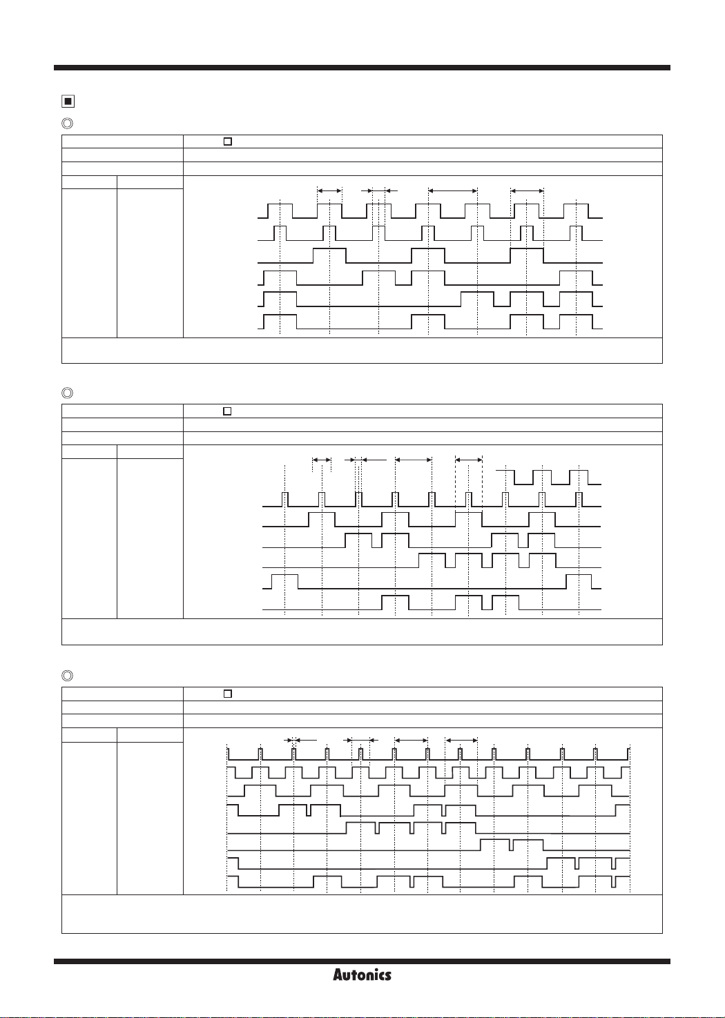
Output Waveform
6-division
Model ENP-111
Shaft revolution angle (°) 0° 60° 120° 180° 240° 300° 360°
Output value 6 1 2 3 4 5 6
Wire color Wire function
Black
Gray
Brown
Red
Orange
White
※
TP1=53°±30', TP2=15°±30' ※P>TS (56°)>TP1 ※P=60°±30'
※
Above waveform is based on the positive logic. (the output waveform of negative logic is opposite to above waveform.)
(Q)
8-division
TP1
TP2
0
)
BCD (2
1
)
BCD (2
2
)
BCD (2
EP (PARITY)
Model ENP-111
Shaft revolution angle (°) 0° 45° 90° 135° 180° 225° 270° 315° 360°
Output value 8 1 2 3 4 5 6 7 8
Wire color Wire function
Black
Gray
Brown
Red
Orange
Yellow
White
※
TP1=39°±30', TP2=15°±30' ※P>TS (42°)>TP1 ※P=45°±30'
※
Above waveform is based on the positive logic. (the output waveform of negative logic is opposite to above waveform.)
TP1
TP2
0
)
BCD (2
1
)
BCD (2
2
)
BCD (2
3
)
BCD (2
EP (PARITY)
-006-P
□
-008-P
□
TP1
H
L
H
L
H
L
H
L
H
L
H
L
TP1
H
L
H
L
H
L
H
L
H
L
H
L
H
L
TP2
TP2
P
:-4------------
P
TS
:.-----------.:
TS
::
7.______TTl____
' '
:
:
'
(Q)
12-division
Model ENP-111
Shaft revolution angle (°) 0° 30° 60° 90° 120° 150° 180° 210° 240° 270° 300° 330° 360°
-012-P
□
Output value 12 1 2 3 4 5 6 7 8 9 10 11 12
Wire color Wire function
Black
Gray
Brown
Red
Orange
Yellow
Green
White
※
TP1=3°±30', TP2=15°±30' ※P>TS (26°)>TP1 ※P=30°±30'
※
Above waveform is based on the positive logic. (the output waveform of negative logic is opposite to above waveform.)
※
The option model for TS (signal pulse) signal with 5-bit (BCD, EP) is available.
TP1
TP2
0
BCD (2
)
1
BCD (2
)
2
BCD (2
)
3
BCD (2
)
BCD (2
×10
EP (PARITY)
0
)
H
L
H
L
H
L
H
L
H
L
_____
H
L
H
L
,7._---+-----+---+--+-------'----+-----1-----'rnr-hn
H
L
H-86
TP1 TP2 P TS
_.._ _ _._
_______
Autonics
.,___rt7rn
'

Absolute Ø60mm Single-turn Shaft Type
Output Waveform
16-division
Model ENP-111
Shaft revolution angle (°)
Output value 16 1 2 3 4 5 6 7 8 9 10 11 12 13 14 15 16
Wire color Wire function
Black
Gray
Brown
Red
Orange
Yellow
Green
White
※
TP1=2°±30', TP2=11.25°±30' ※P>TS (19.5°)>TP1 ※P=22.5°±30'
※
Above waveform is based on the positive logic. (the output waveform of negative logic is opposite to above waveform.)
※
The option model for TS (signal pulse) signal with 5-bit (BCD, EP) is available.
TP1
TP2
0
BCD (2
)
1
BCD (2
)
2
BCD (2
)
3
BCD (2
)
BCD (2
×10
EP (PARITY)
0
)
24-division
Model ENP-111
Shaft revolution angle (°)
Output value
Wire color Wire function
Black
Gray
Brown
Red
Orange
Yellow
Green
Blue
White
※
TP1=8°±30', TP2=3°±30' ※P>TS (11°)>TP1 ※P=15°±30'
※
Above waveform is based on the positive logic. (the output waveform of negative logic is opposite to above waveform.)
TP1
TP2
0
BCD (2
)
1
BCD (2
)
2
BCD (2
)
3
BCD (2
)
0
BCD (2
×10
1
BCD (2
×10
EP (PARITY)
)
)
360-division
Model ENP-11
Shaft revolution angle (°)
Output value
Wire color Wire function
Black
Brown
Red
Orange
Yellow
Green
Blue
Violeet
Gray
White
※
TS=1°±30'
※
Above waveform is based on the positive logic. (the output waveform of negative logic is opposite to above waveform.)
BCD (2
BCD (2
BCD (2
BCD (2
BCD (2
BCD (2
BCD (2
BCD (2
BCD (2
BCD (2
0
)
1
)
2
)
3
)
0
×10)
1
×10)
2
×10)
3
×10)
0
×100)
1
×100)
-016-P
□
0° 22 . 5° 45 ° 67 5 ° 90 ° 112 . 5° 1 35° 157 5 ° 18 0° 202 . 5 ° 225° 247 . 5° 270 ° 292 .5 ° 315 ° 337 . 5 ° 360°
TP1 TP2PTS
H
L
H
L
H
L
H
L
H
L
H
L
H
L
H
L
-024-P
□
0° 15° 30° 45° 60° 75° 90° 105° 120° 135° 150° 165° 180° 195° 210° 225° 240° 255° 270° 285° 300° 315° 330° 345° 360°
24 1 2 3 4 5 6 7 8 9 10 11 12 13 14 15 16 17 18 19 20 21 22 23 24
P
H
L
H
L
H
L
H
L
H
L
H
L
H
L
H
L
H
L
-360-P
□□
0 ° 1 ° 2 ° 3 °
0 1 2 3 4 5 · · · · · · · · · · · · · · · · · · · ·198 199 200 201 200 · · · · · · · · · · · · · · · · · · · · 356 357 358 359 0
H
L
~
H
~
L
H
______i___J'"""
L
H
--~:
L
H
L
H
-----
L
H
---~--
L
H
------+----i---x
L
H
_____
L
H
--~--x
L
4° 5 ° · · · · · · · · · · · · · · · · ·· ··198° 199° 200° 201° 202 ° · · · · · · · · · · · · · · · · · · · · 356° 357° 358° 359° 360°
TS
~
__
......,....__
TP1 TP2
x
::::x
x
::::x
X::
x::
x --
x
'.'.'.'.x
x
::::x
::::x
x
::::x
::::x
~
TS
TS
·~
7.......M......x::::xL...r1.....f7..
7______;____;__
::
X 7 : : r X:::
::
x
J""":i.____
--x
---+--L__
: ,
__ ~ ___
~x::::x
x::::xm_
:x
x:::
~
:x
_____.;....._r-
x----x
x'.'.'.'.x-===1:::::::::==::;-x::::x
____
' '
~x::::x
~x::::x
TS
~
: : L
L
_
L
L
SENSORS
CONTROLLERS
MOTION DEVICES
SOFTWARE
(A)
Photoelectric
Sensors
(B)
Fiber Optic
Sensors
(C)
LiDAR
(D)
Door/Area
Sensors
(E)
Vision
Sensors
(F)
Proximity
Sensors
(G)
Pressure
Sensors
(H)
Rotary
Encoders
(I)
Connectors/
Connector Cables/
Sensor Distribution
Boxes/ Sockets
Autonics
H-87

ENP Series
Control Output Diagram
PNP open collector output NPN open collector output
Rotary encoder circuit Load connection Rotary encoder circuit Load connection
+V
Source current
: max. 32mA
Output
Main circuit
※
Output circuit of each output signal is same.
Connections
00
Resolu ion
Wire color
Power
------
wire
Output
wire
※
1: Insulator external diameter is Ø1.5mm.
※
2: TP1/TP2: Because low resolution model has long output signal period, this signal for enable is easy to determine signal recognition
※
3: EP: Parity signal. It outputs odd parity.
※
Unused wire must be insulated.
※
Encoder case and shield wire must be grounded.
※
N.C (not connected)
※
Output cable must not be short-circuited, because Driver IC is used in output circuit.
※
Do not apply tensile strength over 30N to he cable.
※
White
※
Black
Shield F.G.
Black TP1
Brown 2
Red 2
Orange 2
Yellow N.C 2
Green N.C N.C 2
Blue N.C N.C N.C N C 2
Purple N.C 2
Gray TP2
White EP (PARITY)
Shield F.G.
point about output.
6-division 8-division 12-division 16-division 24-division 360-division
1
+V
1
GND (0V)
0
1
2
Load
0V
※
2
2
2
2
※
2
※
3
+
-
0
1
2
3
0
2
1
2
2
2
3
2
0
×10 20×10 20×10 21×10
Main circuit
0
2
1
2
2
2
3
2
+V
Load
Output
Sink current
: max. 32mA
0V
0
2
1
2
2
2
3
2
1
×10 22×10
0
2
1
2
2
2
3
2
20×10
3
×10
20×100
21×100
+
-
Dimensions
00
3-M4 DP 10
Ø48
Bracket
7
5
30
20
24
15
2
H-88
2-R2.1
R27
3.5
5.5
3-120
-0.005
-0.02
Ø10
0
9
-0.1
0
lf
Coupling
0
0
+0.1
Ø22
Ø10
Do not load overweight on the shaft.
※
Do not put strong impact when insert a coupling into shaft.
※
Failure to follow this instruction may result in product damage.
※
Fix the unit or a coupling by a wrench under 0.15N.m of torque.
※
Whenyouinstallthisunit,ifeccentricityanddeectionanglearelarger,
it may shorten the life cycle of this unit.
※
For parallel misalignment, angular misalignment, end-play terms,
refer to the "Glossary" section of Technical Descrip ion.
※
For flexible coupling (ERB series) information, refer to the ERB series section.
Ø60
-0.021
Ø25
3.4
6
15
25
4-M4
77 22.520
4 3
3.4
Parallel misalignment: max. 0.25mm
Angular misalignment: max. 5°
End-play: max. 0.5mm
Autonics
(unit: mm)
Ø8, 1m
 Loading...