

Page 1
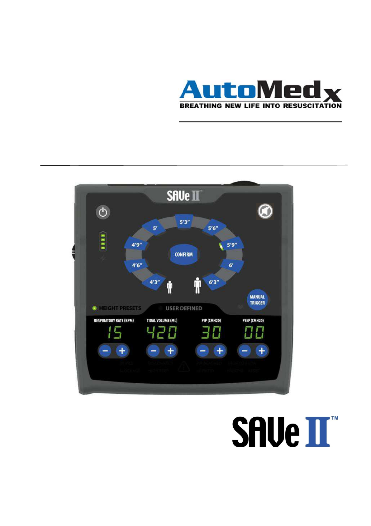
SAVe II Operation Manual
12478
Page 2

Page 3

Preamble
Trademark Information
SAVe II™ is a trademark belonging to AutoMedx, LLC. Copyright© 2018 All Rights Reserved.
The SAVe II™ logo and the names and marks associated with AutoMedx’s products are trademarks
and/or service marks of AutoMedx, LLC. and are registered and/or common law marks in the
United States and various other countries. No portion hereof may be reproduced or transmitted in
any form or by any means, for any purpose other than the recipient’s personal use, without the
express written permission of AutoMedx, LLC.
Contact Information
Manufactured For:
AutoMedx, LLC.
7700 Windrose Ave., Suite G300
Plano, TX 75024
Phone: (972) 586-7500
Fax: (972) 408-4177
Email: [email protected]
Website: www.AutoMedx.com
Authorized Representative in Europe:
(Regulatory Affairs Only)
Emergo Europe
Prinsessegracht 20
2514 AP The Hague, The Netherlands
Tel: (31) (0) 70 345-8570
Fax: (31) (0) 70 346-7299
Document Version
M40100 Rev 4.2 (12/18); Firmware Version R1.0.5
If more than 1 year has elapsed since the date above contact AutoMedx to determine if there have
been any updates to the product or to this manual.
SAVe II OPERATION MANUAL Page 3
Page 4

Notice to Operators
The detailed information and instructions contained within this Operation Manual are designed to
ensure the safe and effective setup, use, and field maintenance of the SAVe II™. The SAVe II must
be setup, operated, maintained and repaired in accordance with the instructions provided in this
manual, accompanying labels and inserts.
It is important that this manual is read and understood in its entirety before operating the
ventilator. Operating or servicing this device without a complete understanding of its
characteristics may cause harm to the patient or user and may permanently damage the device.
The SAVe II is designed for use by trained personnel under the direction of a physician and in
accordance with applicable laws and regulations. This manual describes how to operate and
respond to the ventilator, but does not include instructions on how to respond to the patient.
Please contact AutoMedx if the instructions in this manual conflict with your protocols. Federal
law (U.S.A) restricts this device to sale by or on the order of a licensed medical practitioner.
Outside the United States check local laws for any restrictions that may apply.
Service procedures, including annual calibration verification tests, routine and non-routine
maintenance operations are described separately in the SAVe II™ SERVICE MANUAL (P/N:
M40101). For service information contact: [email protected]
FDA Tracking Requirements
U.S. Federal Law (21 CFR 821) requires the tracking of ventilators. Under this law, owners of this
ventilator are required to register the device and to inform AutoMedx if the device is sold or given
to another organization or destroyed. This allows AutoMedx to notify you of safety updates, a
recall or software updates.
Please send the following information to [email protected]:
Contact name
Title
Organization name
Street address
City, State, Zip
Contact phone number
Email address
Model Number and Serial Number
Disposition of the device
SAVe II OPERATION MANUAL Page 4
Page 5

T
ABLE OF CONTENTS
Preamble ........................................................................................................................................3
Notice to Operators ................................................................................................................................ 4
FDA Tracking Requirements .................................................................................................................... 4
Safety Information .................................................................................................................................. 6
General Warning Statements .................................................................................................................. 7
Caution Statements ................................................................................................................................ 8
Use of Symbols ..................................................................................................................................... 10
INTRODUCTION ............................................................................................................................ 11
Device Overview ................................................................................................................................... 11
Indications for Use ................................................................................................................................ 12
Contra-Indications ................................................................................................................................ 12
Use Environment .................................................................................................................................. 12
Training Requirements .......................................................................................................................... 12
Features ............................................................................................................................................... 13
Risks & Benefits .................................................................................................................................... 13
DEVICE DESCRIPTION ................................................................................................................... 14
User Interface ....................................................................................................................................... 14
Description of Controls, Indicators and Displays ..................................................................................... 15
REFERENCE & NAME ............................................................................................................................. 15
DESCRIPTION ........................................................................................................................................ 15
1
Feature available in devices programmed with firmware release R1.0.4 or later ................................... 15
Device Labeling ..................................................................................................................................... 16
Alarm Dashboard .................................................................................................................................. 18
Device Disposables & Accessories .......................................................................................................... 19
PREPARE FOR USE ........................................................................................................................ 20
USING THE SAVE II ........................................................................................................................ 23
Setup for Use ........................................................................................................................................ 23
Manually Triggered Breaths .................................................................................................................. 33
Clearing Debris from Breathing Circuit ................................................................................................... 35
Alarm Overview .................................................................................................................................... 36
Alarm Quick Reference Guide ................................................................................................................ 37
R
ESPONDING TO ALARMS
.......................................................................................................................... 40
MAINTENANCE ............................................................................................................................. 45
R
EPLACE CONSUMABLES
S
TORAGE
S
CHEDULED MAINTENANCE
A
PPENDIX A– SPECIFICATIONS
A
PPENDIX B – REGULATORY INFO/CLASSIFICATION/ LIMITED WARRANTY
A
PPENDIX C – PRINCIPLES OF OPERATION
A
PPENDIX D - RE-ORDER INFORMATION
A
PPENDIX E – SOFTWARE RELEASE HISTORY
................................................................................................................................................ 48
............................................................................................................................ 47
......................................................................................................................... 48
1
............................................................................................................. 49
..................................................... 50
............................................................................................. 54
................................................................................................. 56
............................................................................................. 57
SAVe II OPERATION MANUAL Page 5
Page 6

avoided, could result in death or serious injury.
“CAUTION” statements alert the reader to potentially hazardous situations, which, if not avoided,
Safety Information
Operators MUST read and understand the following information about Warning and Caution
and statements BEFORE operating the SAVe II™. General warnings and cautions are listed
below. Specific warnings appear throughout the manual where pertinent.
WARNING
“WARNING” statements alert the reader to potentially hazardous situations, which, if not
CAUTION
could result in equipment damage. These situations could indirectly cause death or serious injury
if the equipment damage causes the ventilator to operate improperly.
SAVe II OPERATION MANUAL Page 6
Page 7

General Warning Statements
Restricted Use - The SAVe II is a restricted device that must be used according to its intended
use by properly trained and qualified personnel under the direction of a physician and in
accordance with applicable laws and regulations.
Patient Monitoring - Qualified personnel must constantly monitor patients. Such personnel
should be prepared to troubleshoot alarms, address equipment malfunctions and circumstances
where equipment becomes inoperative.
Alternative ventilation - An alternative means of ventilating the patient should be available at all
times.
Pre-Use Functional Check - The operator should perform a quick functional check to ensure proper
operation before connecting to a patient.
Ventilator Presets - Ventilator height presets may only be used on adult patients. Do not use
presets when ventilating children. Presets are intended to aid operators with the initial setup but
may not be appropriate for extended periods or in all situations. Operators should refer to
appropriate guidelines or their medical director to determine the suitability of these presets for a
given situation.
Sand/Dust/Debris Inside Manifold – Do not operate the SAVe II if sand, dust or other debris have
entered the ports.
Equipment Damage/Malfunction - Do not operate the SAVe II, any components, or accessories
that appear to be damaged, fail Checkout tests, or malfunction in any way. Discontinue use and
immediately contact an authorized service technician or AutoMedx. If equipment is damaged or
behaves in a way that is inconsistent with normal operation, stop use of the device immediately,
unplug, power off the device, and disconnect external oxygen.
Preventative Maintenance - Failure to follow Preventative Maintenance procedures described
in this manual could result in device malfunction. Refer to information on page 45.
Battery - If you suspect the internal battery is damaged, take the unit out of service immediately.
Accessories - Serious harm to the patient may result from the use of unauthorized parts or
accessories. Only use accessories approved by AutoMedx. Refer to information on page 19.
Use with Oxygen Concentrator - Oxygen concentrators are not intended as a primary source of
oxygen and a back- up oxygen source should always be available.
NOT MRI Compatible - Do not put the SAVe II, any components, or accessories inside an MRI
machine.
Use Outside Specified Normal Operating Conditions - The performance of the SAVe II may be
materially affected if it is used outside of the specified NORMAL OPERATING CONDITIONS. Refer to
information on page 12.
Contaminated Environment - Do not use the SAVe II in contaminated environments. The debris
filter is designed to stop particulates, not chemical or biological agents.
Cross Contamination - Do not reuse the Breathing Circuit as it may cause cross contamination
between patients. A
SAVe II OPERATION MANUAL Page 7
patient treated by mechanical ventilation is at risk of infection. Dirty or
Page 8

contaminated equipment is a potential
accessories regularly and systematically before and after each use and following any maintenance
procedure to reduce the risk of infection.
Audible Indicators - Do not allow the ventilator’s Alarm Speaker Port to become covered or
obstructed in any way by stickers, labels, clothing, sand, mud, debris or other equipment.
Noisy Environments - Alarms may be difficult to hear in noisy environments. Take extra
precautions to closely monitor the patient and ventilator in these environments.
Visual Alarm Indicators - Do not cover or obstruct visual alarm indicators in any way. Always
have the user interface in view.
Airway Obstructions - Vomitus and other debris may obstruct the patient end of the Patient
Breathing Circuit. Refer to instructions on clearing debris from the Patient Breathing Circuit on
page 35.
Unintentional Changes - In order to prevent accidental changes to the settings or inadvertently
shutting off the device, verify the user interface is protected from unintentional contact.
Secure Device - During evacuation or transport, it is strongly recommended that the SAVe II be
secured to the patient or litter. Failure to properly secure the SAVe II could damage the device
and could harm the patient by dislodging the Breathing Circuit or airway.
Fire Hazard - If using supplemental oxygen, avoid smoking or open flames. Leaks at oxygen
connections can cause dangerous O2 levels in the vicinity of the leak. To avoid the risk of
ignition, visually inspect oxygen connections before and after connecting supplemental O2 and
take measures to properly ventilate the area. Do not use oil, grease, or combustible lubricants
(only those approved for oxygen use) in contact with any part of the ventilator, regulator, or
cylinder.
source of infection. Clean the ventilator and its
Personal Injury and Electrical Shock - To avoid electric shock hazard, do not open the enclosure
casing and do not use batteries, AC adapters, cables, or external power supplies with visible signs
of damage. Only use power supplies approved by AutoMedx. Refer to information on page 22.
Caution Statements
Risk of Equipment Interference - Potential electromagnetic interference may occur at levels
greater than 20 V/m. Avoid use of the device in environments that may have high
electromagnetic levels. The AC Adapter (Battery Charger) and its associated cables are in
compliance with the requirements of IEC 60601-1-2.
Service Personnel Qualifications - All servicing and repair of the SAVe II must be performed
by a service technician qualified by AutoMedx. Contact AutoMedx at [email protected]
for a SAVE II SERVICE MANUAL (P/N: M40101) and qualification requirements.
Charging Battery/External Power - Only use the Battery Charger specified for use with the
SAVe II. The battery should be charged in accordance with the instructions on page 22.
Wet Environments - If using the SAVe II in a wet environment take precautions and protect
the device by covering it with a protective barrier.
Storage Environment - Storage of the SAVe II outside the specified storage environment may
SAVe II OPERATION MANUAL Page 8
Page 9

materially impact
device.
Battery Replacement & Disposal - The SAVe II battery should only be replaced by qualified
service personnel Batteries should be disposed of according to local environmental legislation.
Refer to SAVE II SERVICE MANUAL (P/N: M40101).
Transport of Lithium-Ion Batteries - Regulations govern the transportation of lithium ion
batteries and devices that have lithium ion batteries. Check the appropriate statutes to ensure
compliance before transporting the device and / or the batteries.
Uncertain Power Sources / Automobile Power Outlets - Before connecting the SAVe II AC
Power Supply to uncertain power input sources, verify the SAVe II internal battery is in good
condition and fully charged. Connecting to an improperly rated power source may damage the
AC Power Supply, preventing the SAVe II battery from charging.
Autoclave/Sterilization - Never place any part of the SAVe II or its accessories in an Autoclave.
Unless otherwise indicated, the SAVe II and its accessories are shipped clean, but not sterile.
Liquids – To avoid inadvertent damage, do not pour or spray liquids directly on the SAVe II. If
liquid cleaners are used, spray on a lint free cloth, then use the cloth to clean the SAVe II and
its accessories.
device performance and permanently damage and/or shorten the life of the
SAVe II OPERATION MANUAL Page 9
Page 10
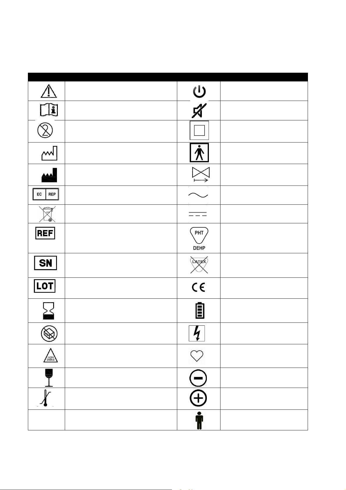
Symbol
Title & Usage
Symbol
Title & Usage
Use of Symbols
C
AUTION
C
ONSULT INSTRUCTION FOR USE
D
O NOT REUSE
D
ATE OF MANUFACTURE
M
ANUFACTURER
A
UTHORIZED REP (EUROPE
W
ASTE CONTAINER
C
ATALOGUE NUMBER
)
ON/O
FF POWER BUTTON
M
UTE
C
LASS II EQUIPMENT
T
YPE BF APPLIED PART
ONE-W
A
D
C
PHTHALATE
AY VALVE
LTERNATING CURRENT
IRECT CURRENT
ONTAINS OR PRESENCE OF
IP24
S
ERIAL NUMBER
B
ATCH CODE
USE-
BY DATE
L
ATEX FREE
CE M
ARKED PRODUCT
B
ATTERY LEVEL
DO N
OT USE IF PACKAGE IS DAMAGED
C
HARGE
NON-STERILE
C
OMPRESSION RATE
F
RAGILE, HANDLE WITH CARE
T
EMPERATURE LIMIT
E
NCLOSURE PROTECTION RATING
D
ECREASE PARAMETER
I
NCREASE PARAMETER
P
ATIENT HEIGHT
SAVe II OPERATION MANUAL Page 10
Page 11
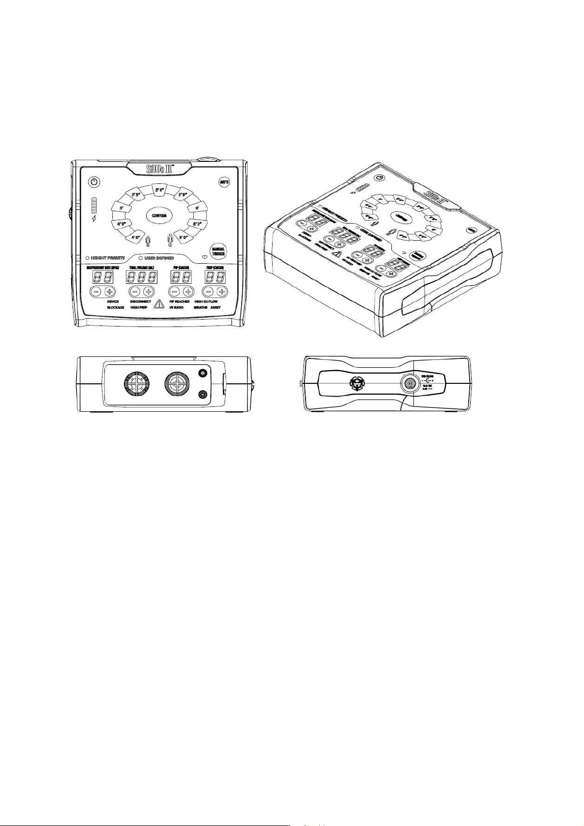
INTRODUCTION
FIGURE 1: MULTIPLE VIEWS OF SAVe II
Device Overview
The SAVe II is designed to be used in lieu of a Bag Valve Mask (BVM) in the pre-hospital
environment or during inter-and intra-hospital transport. It is meant to remove the guesswork
and reduce the operator error associated with BVMs and overly sophisticated transport
ventilators.
The SAVe II uses a battery-powered compressor to deliver air to a patient for up to 10 hours on a
single charge. To support use in austere environments, where compressed oxygen is unavailable
or ill advised, the device does not require compressed oxygen. However, FiO2 can be increased if
compressed oxygen or an oxygen concentrator is available.
Responders can quickly deploy the SAVe II by selecting the patient’s height. The unit dials in a
preliminary tidal volume and respiratory rate appropriate for adults of that size. After initial
setup, users with an appropriate level of training can fine-tune the settings. To mitigate the risk of
patient injury, airway pressure is monitored and users are alerted to potentially dangerous low
and high pressure situations. In a high pressure situation, the pump will stop if the pressure
reaches the peak inspiratory pressure (PIP) cutoff. The PIP setting is adjustable but defaults to 30
cmH2O. Visual alarm indicators located at the bottom of the user interface help the user quickly
troubleshoot issues.
SAVe II OPERATION MANUAL Page 11
Page 12

practitioner. Outside the U.S.A. check local laws for any restrictions that may apply.
performance of the SAVe II may be materially affected if it is used outside of the
ENVIRONMENTS. This may result in ventilator failure and/or har
m to the patient.
Indications for Use
The SAVe II series is intended to provide short-term ventilatory support to adults during CPR or
when Positive Pressure Ventilation (PPV) is required to manage Acute Respiratory Failure (ARF).
The SAVe II series is appropriate for adults that weigh at least 45 kg (approximately 99 lbs.). It is
intended to be used in the pre-hospital, field hospitals and transport environments.
Federal law (U.S.A) restricts this device to sale by or on the order of a licensed medical
Contra-Indications
ABSOLUTE CONTRA-INDICATIONS
The SAVe II should not be used in situations where Positive Pressure Ventilation (PPV) is contraindicated.
RELATIVE CONTRA-INDICATIONS
Do not use the device for extended periods without monitoring blood gases. As duration of use
increases, the need for close monitoring of CO2 and O2 levels also increases.
Do not set PEEP above zero (0) when performing CPR.
Spontaneously breathing patients may not synchronize with ventilator. Consider discontinuing
use if a spontaneously breathing patient has difficulty synchronizing with the device.
Use Environment
NORMAL OPERATING ENVIRONMENT
The SAVe II is intended for use in pre-hospital and in-hospital settings. Performance
specifications are based on use in environments with ambient temperatures of 0 to 50°C (32
to 122°F), relative humidity from 15 to 95%, and atmospheric pressures from 70 to 110 kPa.
EXTREME OPERATING ENVIRONMENT
Attempting to operate the ventilator outside the temperatures range of -10 to 50°C (14 to 122°F)
may result in ventilator failure and harm to the patient.
WARNING: The
specified NORMAL OPERATING CONDITIONS. If at the discretion of the medical director, the
device is used outside of the specified NORMAL OPERATING CONDITIONS, but within specified
EXTREME OPERATING CONDITIONS, the Operator must practice extra patient vigilance. Do NOT
at any time operate or store the Device in environments outside specified EXTREME OPERATING
Training Requirements
Operators must be familiar with the contents of this manual and trained to provide primary
response to a respiratory emergency.
SAVe II OPERATION MANUAL Page 12
Page 13

Features
Height based presets enable rapid setup
Presets dial in lung protective ARDSnet based parameters based on ideal body weight (6
ml/kg)
Small size and weight make it one of the most portable ventilators on the market
Ventilate a patient on the internal battery for 10 hours (runtime varies based on settings)
Adjustable tidal volume (TV), respiratory rate (RR), peak inspiratory pressure (PIP) and
positive end expiratory pressure (PEEP)
Alarm Dashboard simplifies troubleshooting
No compressed gas tank required
Deliver FiO
Displays breath to breath PEEP and PIP measurements
up to 100% using included oxygen reservoir and flow regulated oxygen source
2
Risks & Benefits
The SAVe II is designed to enable a medic or other first responder with limited training to
provide life-sustaining ventilation until the patient can be evacuated to a higher level of care.
The device is easy to use, lightweight, and intended to be used on the battlefield, in the prehospital environment or during transport. The operator simply selects the height of the patient
and the device dials in an ARDSnet Protocol recommended tidal volume of 6 ml/kg of ideal body
weight. These presets may not be appropriate for all patients or all conditions. The operator
must continue to monitor the patient and make adjustments as necessary.
The SAVe II has a number of benefits over a bag-valve-mask (BVM). First, it offers a breath-tobreath consistency not achievable with a BVM. This is especially important in high stress
situations where studies have demonstrated rescuers are prone to hyperventilating patients.
The SAVe II delivers a consistent tidal volume at a consistent rate. Second, the SAVe II, unlike a
BVM, frees up the responder to address other injuries, attend to other patients or further assist
in the evacuation. Third, the SAVe II will provide up to 10 hours of ventilation on a full charge
(time varies depending on settings). It is impractical to expect a medic to manually ventilate a
patient for that duration with a BVM. The SAVe II will detect a patient’s inspiratory effort and
automatically trigger a breath.
Unlike Pneumatic Resuscitators, the SAVe II does not require compressed air to operate,
however it will accept low-pressure supplemental oxygen if a higher FiO2 is needed. Devices
relying on high-pressure oxygen tanks in a combat zone pose a fire and explosion hazard, tend to
be large and only ventilate for a short period of time.
The medic administering care must monitor the patient to ensure adequate gas exchange is
occurring. The SAVe II is designed with multiple system checks to monitor proper operation of
the device and safety of the patient. If an alarm condition occurs, the SAVe II will emit both a
visual and audible alarm. In addition, depending on what triggered the alarm, the SAVe II will
limit functionality as necessary to avoid patient injury. For example, the device will trigger an
alarm and cutoff power to the pump when the delivery of additional air exceeds the peak
inspiratory pressure (PIP) limit. This safety feature is designed to prevent over inflation and
alerts the medic to fix the fault that triggered the alarm.
SAVe II OPERATION MANUAL Page 13
Page 14

DEVICE DESCRIPTION
User Interface
Device Labels
Alarm Dashboard
Device Disposables & Accessories
User Interface
Device controls, indicators and displays are located on the front panel of the device and are
organized based on task for rapid setup and troubleshooting.
The device is controlled using buttons. With the exception of Power On/Off, Mute and Manual
Trigger, control changes require confirmation to prevent inadvertent changes. Controls
requiring confirmation are associated with adjusting ventilator parameters and require
operators to select (press) the appropriate Height Preset or +/- parameter control button until
the desired setting is reached then press Confirm. The parameter display will blink with the
prospective setting for 10 seconds or until the confirm button is pressed. If not confirmed, the
device will revert back to the current device setting and the numerical parameter displays will
turn solid.
Green LED indicators communicate the current normal operating status of the device. Red
alarm codes and the audible alarm indicator signal an alarm condition. Solid indicators are
intended to only communicate information such as a current device settings or past alarm
conditions. Blinking indicators are intended to signal that operator intervention is needed due
to a control change requiring confirmation or an active alarm condition.
Green numerical parameter displays communicate device parameter settings and measured
pressures. Similar to blinking indicators, blinking parameter displays are intended to signal that
operator action is needed to confirm a setting. If the Confirm button (see above) is pressed
when all of the parameter displays are solid then measured pressures (PIP & PEEP) will be
displayed for 3 seconds.
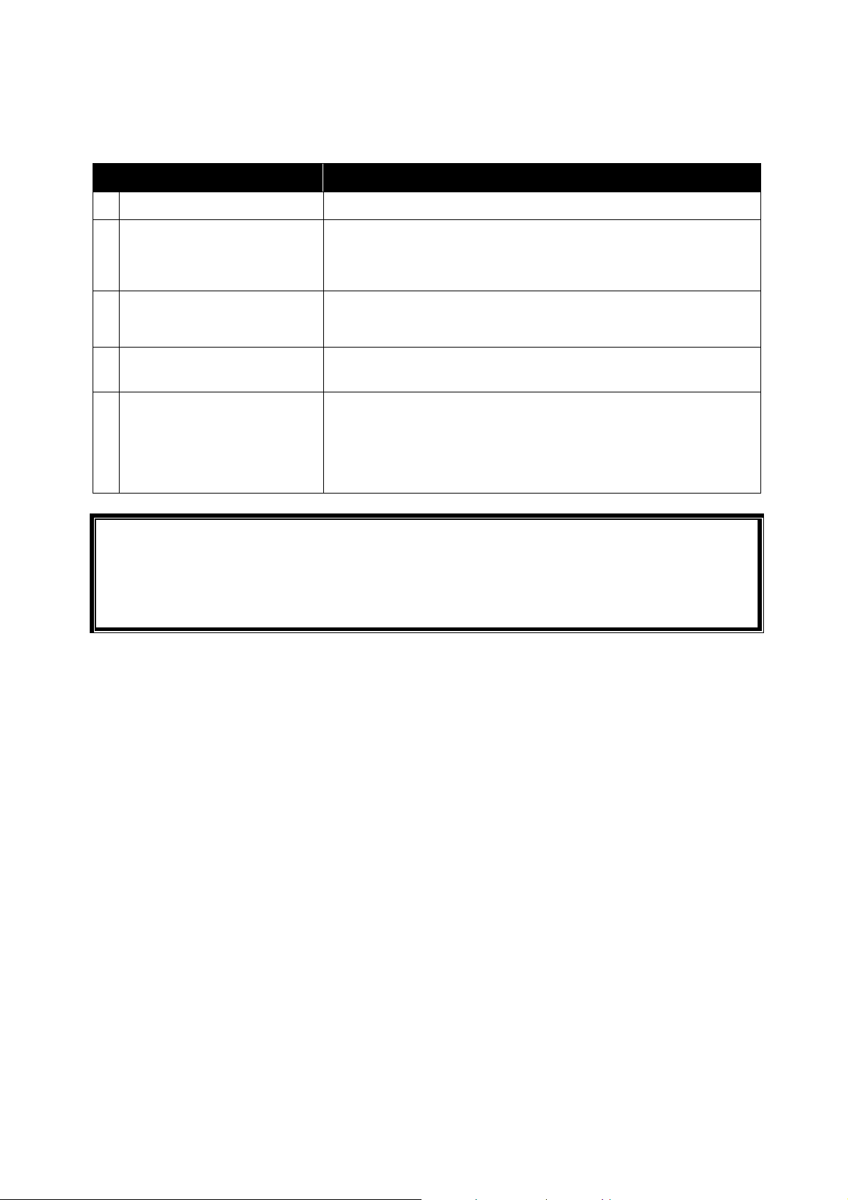
SECTION
UPPER UI PANEL
(Gray)
LOWER UI PANEL
(Black)
DESCRIPTION
Primary indicators, displays and controls generally used during
initial setup.
Secondary indicators, displays and controls generally used to
monitor and fine tune ventilator parameters.
ALARM PANEL
(Black – Bottom
Alerts operator to potential issues with operation of device.
of UI Panel)
SAVe II OPERATION MANUAL Page 14
Page 15

Control used to turn device On and Off. Press for 1 second
to turn on.
Control and indicator used to set default ventilator parameters based
3 Battery Life
Indicates remaining battery life.
4 Audible Alarm Indictor
Indicates an active alarm condition.
5 External Power
Indicates external power is connected.
6 Adult Height Presets
Indicates device set using preset patient hei
ght parameters.
7 User Defined
Indicates device set to user defined parameters.
Control and display used to set the RESPIRATORY RATE (RR) and
Control and display
used to set the TIDAL VOLUME (TV) and monitor
Control and display used to set the PEAK INSPIRATORY PRESSURE
Control and display used to set the POSITIVE END
-
EXPIRATORY
Indicator blinks at
a rate of 100/minute to aid users performing chest
13 Manual Trigger
Control used to
deliver a breath at the set tidal volume.
Control and indicator used to prevent unintended
changes. Blinking
Silences an active audible alarm for 120 seconds. New alarm will
1
Feature available in devices programmed with firmware release R1.0.4 or later
Description of Controls, Indicators and Displays
REFERENCE & NAME DESCRIPTION
1 Power On/Off
2 Adult Height Presets
8 Respiratory Rate
9 Tidal Volume
10 PIP
11 PEEP
Hold for 3 seconds to turn off. The high priority audible alarm
indicator will activate 1 second prior to shut down.
on patient height and monitor current setting.
monitor the set number of breaths delivered each minute.
the set volume in milliliters of gas delivered each breath.
(PIP) limit (Pressure Cutoff). Once the setting is confirmed the display
stays fixed, however, the device measures the peak pressure breath
to breath. To see the last measured Peak Inspiratory Pressure at the
PATIENT CONNECTION PORT press the confirm button1.
PRESSURE (PEEP) and display the set PEEP of each breath. By pressing
the confirm button during normal operation, the device will display
the measured PEEP maintained in the BREATHING CIRCUIT at the end
of exhalation1.
12 Compression Rate
14 Confirm
15 Mute
compressions when device is in MASK CPR mode (RR set to zero (0).
indicates the ventilator parameter settings must be confirmed to
become active. When all parameter settings are confirmed (solid)
and no changes are pending, pressing the Confirm button will cause
the most recent measured PIP and PEEP values to be displayed in the
PIP and PEEP parameter displays for 3 seconds (Refer to instructions
on page 29)1.
override. If alarm condition still presents after 120 seconds the
audible alarm will resume.
SAVe II OPERATION MANUAL Page 15
Page 16
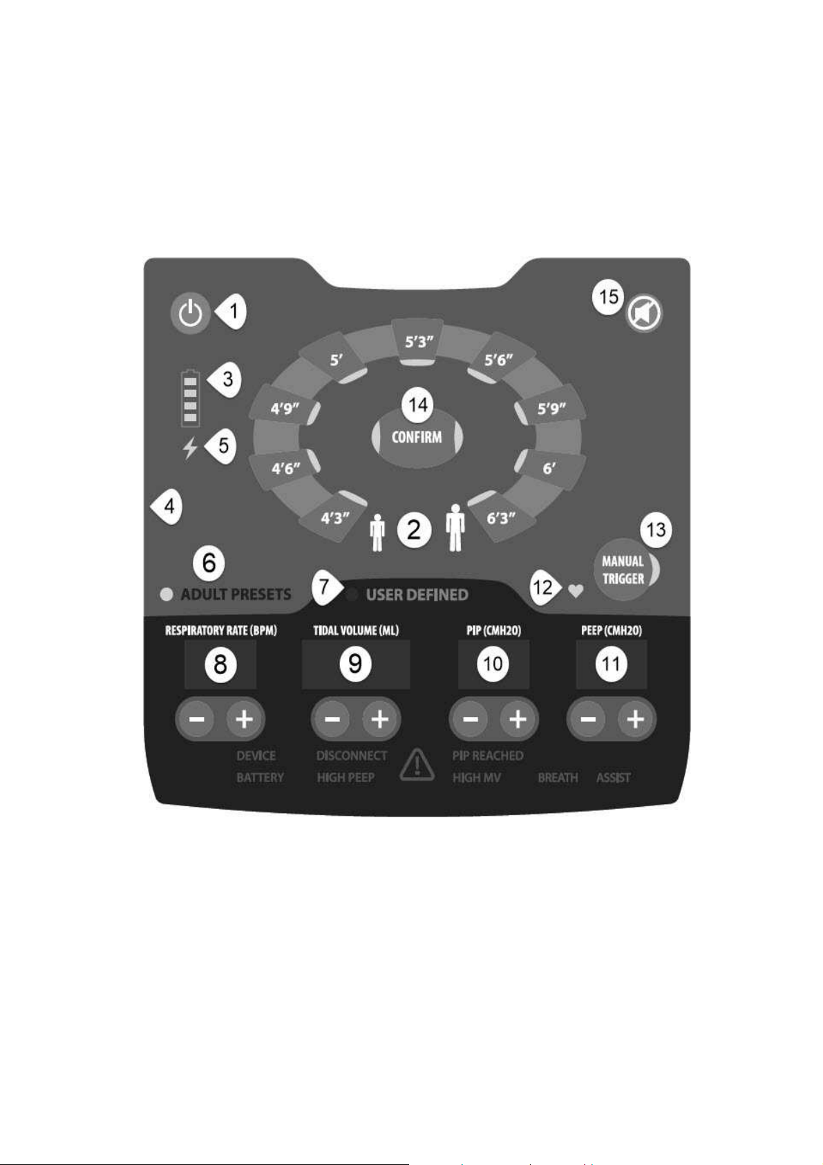
Device Labeling
F
RONT PANEL LABEL / USER INTERFACE
SAVe II OPERATION MANUAL Page 16
FIGURE 2: USER INTERFACE
Page 17
B
ACK PANEL LABELS
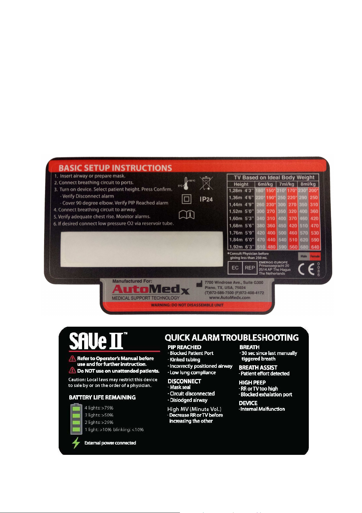
The SAVe II back panel has two labels. These labels are intended as a reference to users who have
read this manual. The back panel device labels include information concerning:
Basic setup instructions
Tidal volume reference table for advanced users
Device Serial Number
Quick alarm troubleshooting information
Battery capacity reference
SAVe II OPERATION MANUAL Page 17
Page 18
connected to an appropriate external power source.
actively exhaling during the exhalation phase.
ASSIST
patient triggered breath has been delivered.
Alarm Dashboard
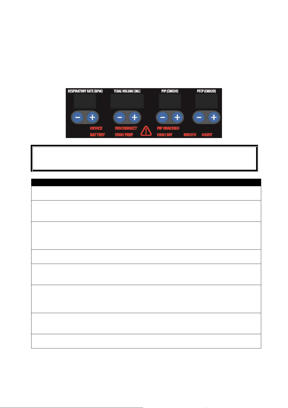
The Alarm Dashboard is located at the bottom of the user interface. Alarm codes will illuminate in
red to alert the operator of various conditions:
Warning: Never cover or obstruct the alarm panel. Operator must have a clear view of the panel
at all times when the device is connected to the patient, especially in noisy environments where
caregiver may not hear alarms.
ALARM CODE DESCRIPTION AND LIKELY CAUSE
DEVICE
The device is outside its temperature range or a software,
mechanical or electrical issue has been detected.
The minimum pressure threshold has not been reached during
DISCONNECT
an inhalation. Most likely caused by a disconnection of the
Breathing Circuit tubing or patient airway.
The set Peak Inspiratory Pressure Limit has been reached.
PIP REACHED
BATTERY
Possible causes include: blockage of Breathing Circuit or airway,
low lung compliance (stiff lungs), excessive tidal volume, and
tension pneumothorax.
Less than 10% of battery capacity remains. The unit must be
The measured PEEP is 5 cmH2O above set PEEP. Most likely
HIGH PEEP
causes are blockage of the exhalation port or the patient
The combination of TV/RR requires a flow rate that exceeds the
HIGH MV
(Minute Vol.)
BREATH
(CPR Mode)
BREATH
pumps ability to deliver at an I:E ratio of 1:2. The device will not
permit operator to select these TV/RR combinations. Refer to
information on page 30.
More than 30 seconds have passed since the last manually
triggered breath. Only active in MASK CPR MODE (RR set to
zero).
Indicates a patient inspiratory effort has been detected and a
RESPONSE
Page 43
Page 40
Page 41
Page 42
Page 43
Page 44
Page 44
Page 44
Refer to information on page 40 for instructions detailing how to respond to alarms.
SAVe II OPERATION MANUAL Page 18
Page 19
The Hazard indicator will illuminate for all errors and alarms;
ITEM
PART #
DESCRIPTION
Filter
other particl
es.
Attenuator or
Oxygen
Reservoir is not being used.
or Air Intake Cap is not in use.
M40090
Power Cable (Type A)
E11021
Connects the AC
Power Supply to
external
power.
Head Harness
1
E11001
Assists user in securing mask to patient.
Syringe
however, it may be the only indicator if the battery is
disconnected or there is a major malfunction.
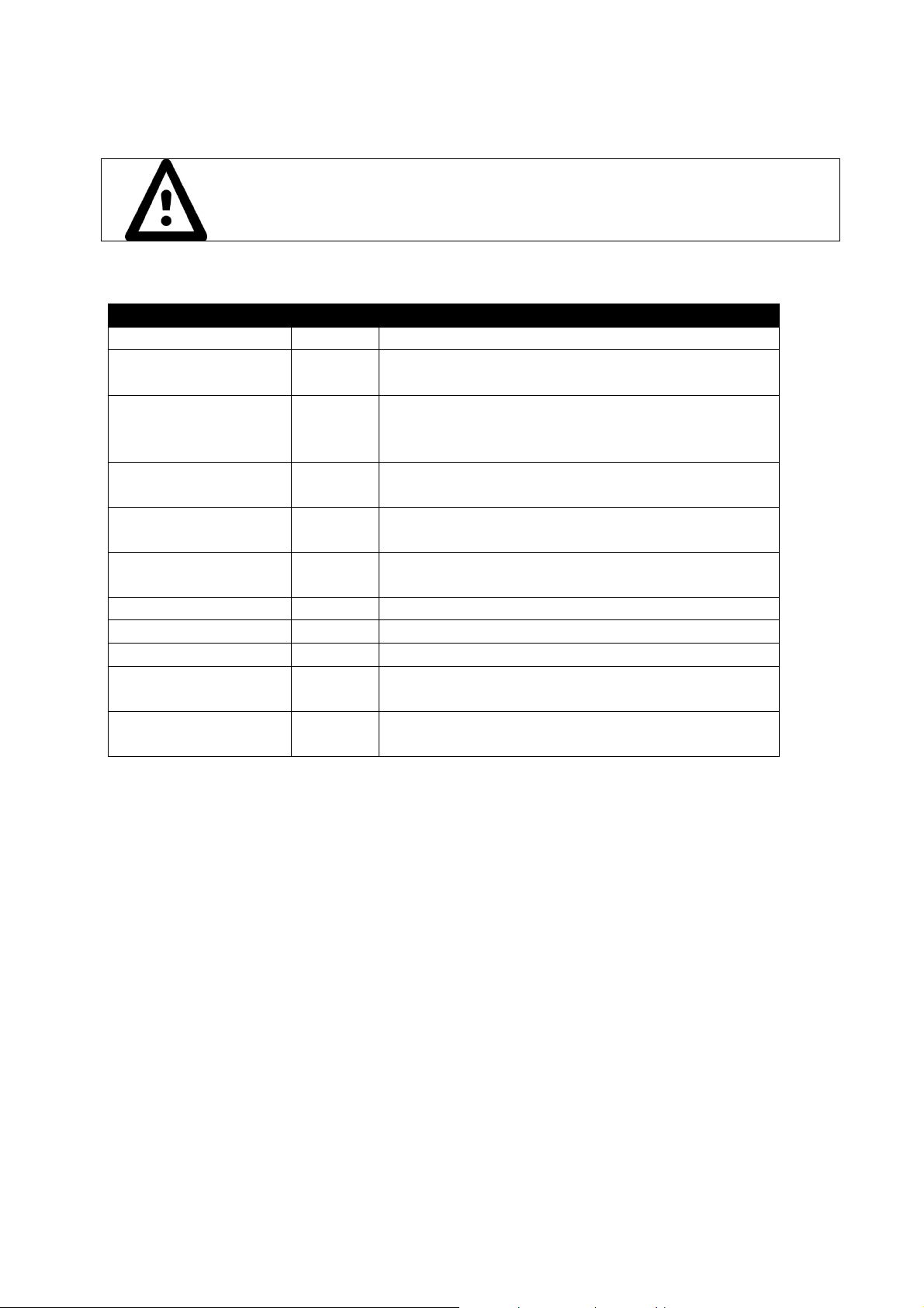
Device Disposables & Accessories
Breathing Circuit
Air Intake Debris
M40105 Channels air to and from the patient’s airway.
F20053
Protects internal components from dust, dirt and
Protects the Debris Filter from direct exposure to
Air Intake Cap
Oxygen Reservoir
Noise Attenuator
AC Power Supply
Hard Carrying Case
1
Mask
Mask Inflation
1
1
Items provided for convenience of user and may not be included in all kits. Please check with your distributor.
F20059
M40092
M41112
E52240 /
F20055
E11000
E10996
particles and water during storage or use when the
Allows delivery of up to 100% FiO2 using a flow
regulated oxygen source.
Mitigates device noise when the Oxygen Reservoir
Supplies device and battery with external power.
Protects the system during transport and storage.
Basic non-invasive interface between Breathing
Circuit and patient.
Used to re-inflate mask if necessary.
SAVe II OPERATION MANUAL Page 19
Page 20

1 EA Ventilator
M50012
1 EA Breathing
Circuit,
Rugg
edized,
Disposable,
Single
- Use M40105
1 EA Air Intake
Debris
Filter,
Disposable
F20053
1 EA AC Power
Supply
/ Battery Charger
E52240
1 EA Power
Cable
(Type
A) E11021
1 EA
Mask and Inflation Syringe (included in some kits)
M40106
1 EA
Head Harness (4
point) (included in some kits)
E11001
1 EA Attenuator
(Sound
Dampening
U
Shaped
Tube),
Reusable
M41112
1 EA Oxygen
Reservoir, Reusable
M40092
1 EA
Air Intake Cap
F20059
1 EA Operator’s
Manual
M40100
US, Kit. The specifics of your
PREPARE FOR USE
To prepare the SAVe II for rapid deployment, operator must:
1.
Unpack device
2.
Verify required contents are packaged in kit
3.
Verify debris filter is installed
4.
Verify battery has adequate charge
Step 1: Unpack Device
Inspect the transport container for evidence of damage during transit. If damaged, notify the
delivery service immediately. Carefully remove the ventilator and all accessories from the
transport container. Confirm you have received all items listed on the packing slip. Notify an
authorized sales representative or AutoMedx of any discrepancies. Examine the ventilator and
accessories for visible damage. If damaged, notify AutoMedx. Unless otherwise indicated, the
SAVe II and its accessories are provided clean, not sterile. It is best to keep all accessories
packaged until needed.
Step 2: Verify Contents
INCLUDED IN SAVE II KIT
QTY DESCRIPTION PART NUMBER
Note: An airway is required for use but may not be included with kit. Operators must identify an
airway appropriate for the situation and have it ready for use. The SAVe II should always be
packaged with an airway that is appropriate based on the training of the provider and needs of
the patient. Consult your medical director. Only use accessories approved by AutoMedx for use
with the SAVe II. To verify if an airway is approved for use with the SAVe II, contact
The above list describes the configuration of the Standard, 70100Hconfiguration may vary based on the country or region of use and the specific requirements of
your organization.
SAVe II OPERATION MANUAL Page 20
Page 21
Step 3: Verify Debris Filter Installation
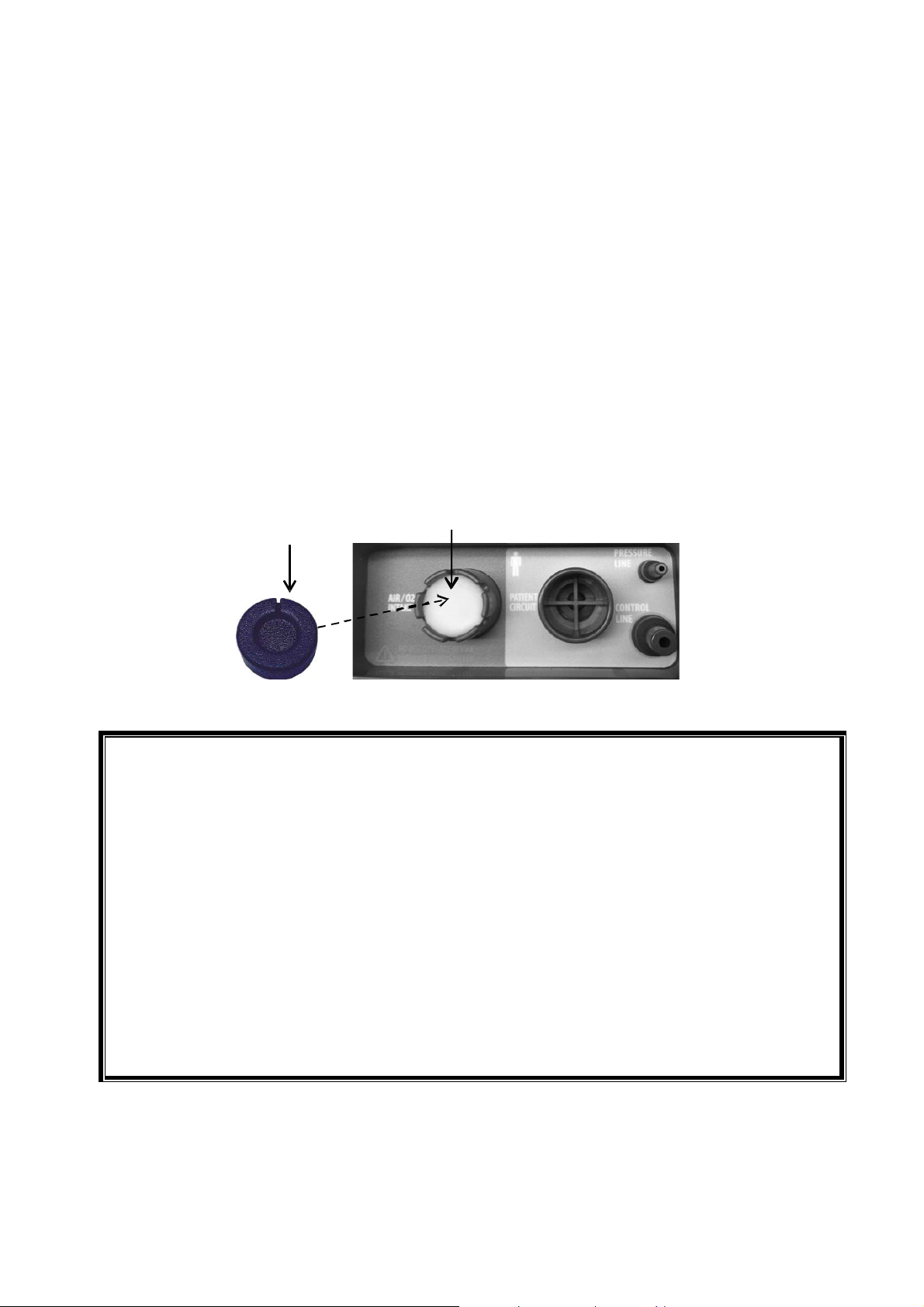
The DEBRIS FILTER (P/N: F20053) is intended to protect the internal components of the SAVe II
system from dust, dirt and other particles. Two debris filters must be placed inside the “Air/O2
Intake” port of the SAVe II at all times.
The AIR INTAKE CAP (P/N: F20059) protects the Debris Filter from direct exposure to particles
and water during storage and use when the Attenuator or O2 Reservoir is not being used. The
notched edges of the air intake port allow air to flow to the patient even when the Air Intake Cap
is in place. In particularly dusty or sandy environments the air intake cap should be used instead
of the Attenuator.
Inspect the Air Intake Debris Filter prior to each patient use and replace if there is any sign of
exposure to moisture, dust, sand or other debris. AutoMedx recommends replacing the debris
filter after each patient use due to the austere environments in which the SAVe II is often used.
The debris filter may require replacement less often if the device is not being used in particularly
dirty or dusty environments.
AIR INTAKE CAP AIR I NTAKE PORT & DE BRIS FIL TER
WARNING:
FIGURE 3: AIR INTAKE PORT, DEBRIS FILTER & PORT CAP
Failure to properly maintain the debris filter can decrease delivered tidal volumes to the
patient as well as lower the life expectancy of the unit due to increased workload on the
pump motor.
Immediately take device out of service if dust, sand or other debris have entered the
internal SAVe II system. The delivered tidal volume may decrease significantly without
alarming.
Never operate the unit without a filter in place. Two clean Debris Filters must be in place at
all times
Never use a wet or moist Debris Filter.
The Debris Filter is not designed to filter chemical or biological agents and will not protect
the patient from contaminated environments.
Only use filters designed for the SAVe II. Using other filters may impact device
performance.
The AIR INTAKE CAP should be used when the Attenuator or O2 reservoir is not being used.
SAVe II OPERATION MANUAL Page 21
Page 22
Illuminated LEDs
Usable Battery Capacity
4 LEDs
> 75%
3 LEDs
> 50%
2 LEDs
> 25
%
1 LED (Blinking)
< 10%
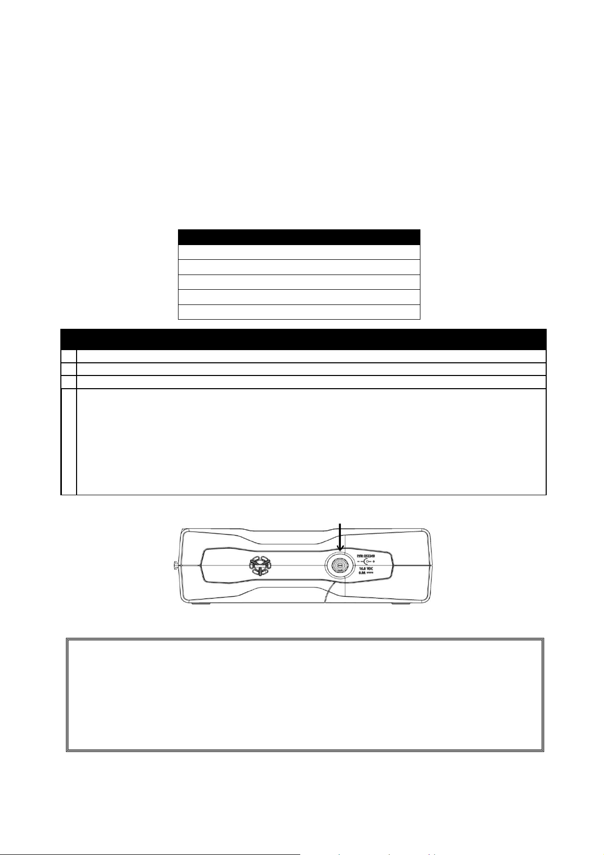
1 Connect
AC Power Supply
to
appropriate
power
source.
(See
POWER
INPUT
specifications
on
2 Connect
other
end of AC Power Supply
to Power
Input
Port.
(See
Illustration
below)
3 Verify
charge
indicator
light
(lightning
bolt icon)
is
illuminated.
Monitor
charge
status
using
Battery
Level
Indicator.
Approximate
charging
time
for a battery
that
settings. The unit is fully charged when the LED on the Power Supply turns gre
en.
Power Supply
, follow power
input specifications of 100
– 240 VAC, 50
– 60 Hz.
Step 4: Charge Battery
The SAVe II is primarily powered by an internal lithium-ion battery. The battery is re-charged by
connecting the SAVe II to external power (100 – 240 VAC, 50 – 60 Hz) via the AC POWER SUPPLY
(P/N: E52240). When the SAVe II is connected to external power by the AC Power Supply it can
simultaneously run and charge the internal lithium-ion battery. Please note that if the battery is
completely discharged that in rare instances it may take a few minutes of charging before device
has enough power to run.
1 LED
> 10%
TO OPERATE FROM EXTERNAL POWER AND RECHARGE THE BATTERY:
is empty
4
1 hour – 30% charged,
2 hours – 60% charged,
3 hours – 85% charged,
3:45 hours – 100% charged.
If the SAVe II is running, the charge time will increase 15% to 40% depending on the device
POWER INPUT PORT
FIGURE 4: POWER INPUT PORT
CAUTION:
The battery should only be replaced by qualified biomedical equipment technicians.
Only use AC Power Supplies from AutoMedx or its authorized distributors. The SAVe II AC
Power Supply has been carefully selected to meet all required standards for a medical
device as well as for safely charging the SAVe II lithium ion battery.
Use caution when connecting to unreliable power sources. When connecting the AC
SAVe II OPERATION MANUAL Page 22
Page 23
USING THE SAVE II
1
Locate
an
unused
SAVE
II
PATIENT
BREATHING
CIRCUIT
(P/N:
M40105)
in
its original
2 Remove
Patient
Breathing
Circuit
from
packaging.
3 Verify circuit is properly assembled with
the Active Con
trol Valve cap securely attached and
no
visible signs of damage.
3 Open
the “Breathing Circuit
Port
Cover” located on the ventilator.
4 The three ports grouped together are different sizes. Work from largest to smallest.
Setup for Use
Manual Trigger Breaths
Clear Breathing Circuit of Debris
Alarms
Setup for Use
1. Connect Patient Breathing Circuit to unit
2. Verify proper operation
3. Connect Patient Breathing Circuit to Airway
4. Select ventilator parameters
5. Optional: Connect Supplemental Oxygen or Noise Attenuator
6. Monitor patient and respond to alarms (Refer to info on page 40)
Step 1: Attach Breathing Circuit
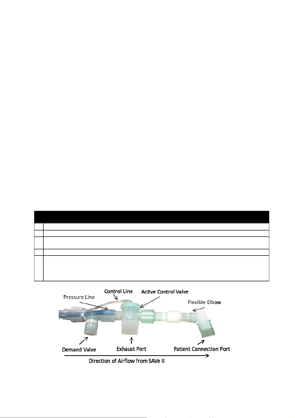
Prior to use, inspect the circuit to verify it has been assembled correctly (pictured below) with no
visible signs of damage. Verify a Debris Filter has been placed inside the Breathing Circuit
Demand Valve if using in particularly sandy or dusty environment. Do not “jam” the Debris Filter
into the one-way valve of the Demand Valve. This may increase the inspiratory resistance of
spontaneously breathing patients. The Demand Valve is meant to allow a patient to draw in
ambient air if they begin to breathe spontaneously.
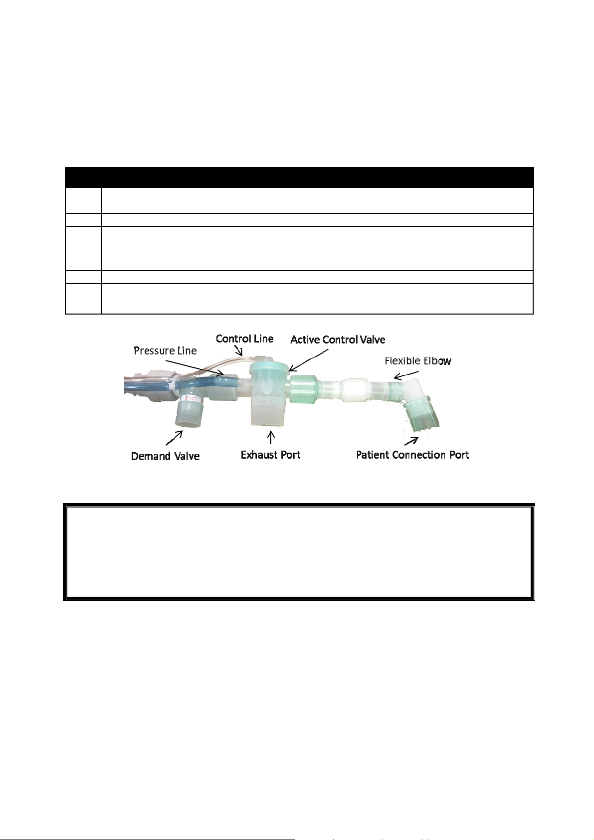
CONNECT THE SAVe II PATIENT BREATHING CIRCUIT BY:
Connect the large grey tube to the port labeled Breathing Circuit.
Connect the tube with a white end to the port labeled Pressure Line.
Connect the small blue tube to the smallest port which is labeled Control Line.
FIGURE 5: BREATHING CIRCUIT
SAVe II OPERATION MANUAL Page 23
Page 24

The Control and Pressure Lines of the SAVe II Breathing Circuit contain phthalates. These lines
are not in the air pathway so the patient does not come into contact with phthalates.
normally
Limit
is reached
again
WARNING:
Do not block the BREATHING CIRCUIT EXHAUST PORT.
If the Demand Valve is improperly connected the patient will not be able to breath
spontaneously.
The Demand Valve’s two internal one-way valves must be oriented in the direction of airflow.
Failure to properly connect the Breathing Circuit and accessories may materially impact
device performance.
Only use Breathing Circuits expressly approved by AutoMedx for use with the SAVe II
Ventilator.
Do not disassemble Patient Breathing Circuit unless required to do so to clear debris.
Do not use damaged or misassembled Breathing Circuits.
Always dispose of the circuit after each patient use following the institutional guidelines for
biologically contaminated material. Reusing the circuit can result in cross contamination
between patients.
Step 2: Verify Proper Operation
Verify basic functionality and safety of the SAVe II prior to each mission or immediately prior to
use.
Test
Verify
Disconnect
Alarm
Verify PIP
Reached
Alarm
Procedure
1. Connect circuit to unit. Do
not connect to airway.
2. Turn device on
3.
Select and confirm any
height preset
4.
Completely block “Patient
Connection Port”
Acceptance Criteria
•
Disconnect visual alarm indicator
activates within 2 breaths and starts
blinking
•
Audible alarm indicator activates
•
Pum p continues to o perate
•
PIP Limit visual alarm indicator
activates within 1 breath and starts
blinking
•
Pump turns off for a few seconds and
then turns on briefly again until PIP
WARNING: If the device fails the checkout, do not use and have it serviced immediately.
SAVe II OPERATION MANUAL Page 24
Page 25
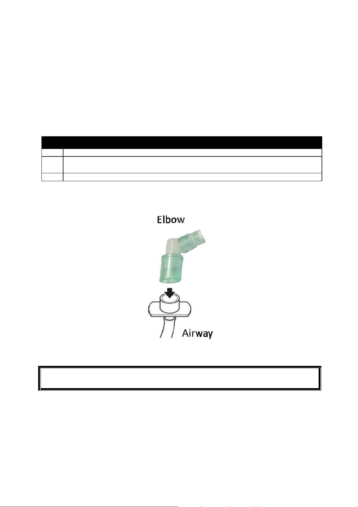
1 Attach/Secure
airway
to
patient
by
following
Instructions
For Use of selected
airway.
2 Attach
Patient
Breathing
Circuit
to
Airway
by
connecting
Patient
Connection
Port
to
3 Verify
the rise and fall of the chest
as
well as the absence
of
ALARMS.
a cap.
Step 3: Attach Airway
An airway is necessary to channel air from the Patient Breathing Circuit to the patient’s lungs. The
Breathing Circuit can be connected to a variety of airways using the standard 22mm O.D. / 15mm
I.D. patient connection port. The SAVe II should always be packaged with an airway (Mask, King-LT,
ET Tube, etc.) that is appropriate based on the training of the provider and needs of the patient.
Read and follow separate airway Instructions for Use.
ATTACH AIRWAY BY:
Airway.
SAVe II OPERATION MANUAL Page 25
FIGURE 6: PATIENT BREATHING CIRCUIT
WARNING: Do not use a mask with a filter and make sure any ports on the mask are sealed with
Page 26
2
Device activates using Preset Height parameters
4’ 3” 129 20 250 5.0 30 0
4’ 6” 137 21 250 5.3 30 0
4’ 9” 145 21 260 5.5 30 0
5’ 0” 152 20 300 6.0 30 0
5’ 3” 160 18 340 6.1 30 0
5’ 6” 168 16 380 6.1 30 0
5’ 9” 175 15 420 6.3 30 0
6’ 0” 183 14 470 6.6 30 0
6’ 3” 191 13 510 6.6 30 0
1
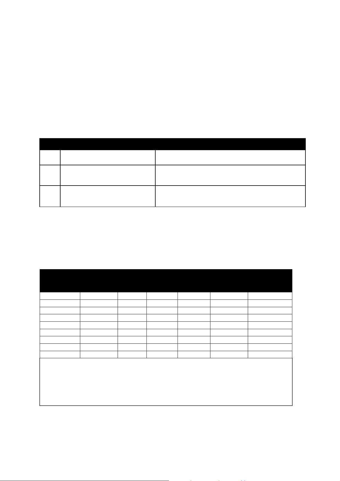
The Tidal volume presets were calculated using 6 ml/kg of a male patient’s ideal body
further adjustments. This label is also included
on page
17 of this manual.
Step 4A: Select Adult Patient Height
Height presets were designed to enable minimally trained providers, who may otherwise use a
BVM, to deliver a more targeted and consistent therapy than can be achieved with a BVM in the
pre-hospital or transport environment. The provider simply selects the patient’s height. Preset
parameters are automatically dialed in as outlined in the below chart. This Basic Setup is quick
and removes the guesswork and operator error associated with bagging patients in high stress
environments or attempting to setup a more complex ventilator.
OPERATOR ACTION
1 Verify Proper Operation
Select and confirm appropriate
Preset based on patient height
Verify adequate chest rise and
3
monitor Patient and Alarms
EXPECTED DEVICE RESPONSE
See previous section
No active alarms (blinking). Refer to information on
page 40 for details on how to respond to alarms.
Note:
An alternate Height Preset button may be selected and confirmed at any time.
Ventilator height presets may only be used on adult patients. Height presets are only a guide
and do not replace clinical decision making. Ventilator parameters may need to be adjusted.
MANUAL TRIGGER is always active. Be careful to avoid inadvertent operation.
HEIGHT
(FT’ IN”)
HEIGHT
(cm)
RR
(BPM)
TV1
(ml)
Minute
Volume
PIP
(cmH2O
PEEP
(cmH2O)
weight (IBW). The respiratory rate was set to achieve minute volumes between 5 and 6.6
liters depending on the size of the patient. Females receive on average 6.5 ml/kg of ideal
body weight. The presets do not go below 250 ml so patients at 4’3” and 4’6” are receiving
higher relative tidal volumes. Refer to the specifications on page 49 for the tolerances of
each parameter. There is a look up table on the back of the device to help provider make
SAVe II OPERATION MANUAL Page 26
Page 27
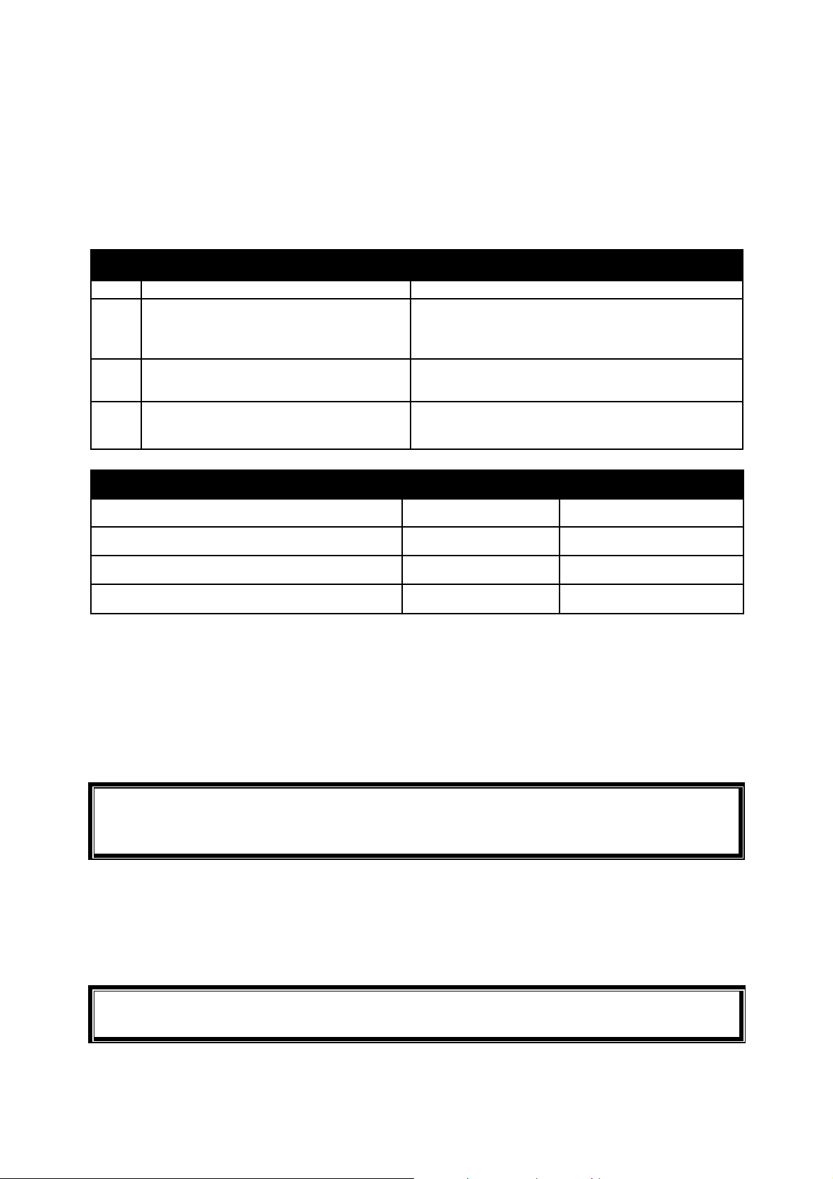
Step 4B – Dial in Parameters (Advanced Users Only)
1 Setup
based
on
patient
height
See previous
section
is pressed
the unit operates
at
previously
CPR Mode
to
prevent
false
triggering caused
by
chest
compressions.
than
indicated
will be delivered
to
patient.
While the height presets enable Basic providers the ability to deliver a more targeted and
consistent therapy than is possible with BVMs, an Advanced User can adjust the settings as
necessary.
OPERATOR ACTION
Adjust ventilator parameters using +/-
2
control buttons
EXPECTED DEVICE RESPONSE
The adjusted settings blink until the Confirm
button is pressed. Until the Confirm button
Display of desired setting transitions from
3 Confirm selection
4 Monitor patient and alarms
blinking to solid and new settings become
No active alarms (blinking). Refer to information
on page 40 for details on how to respond to
PARAMETER
Respiratory Rate (RR)
Tidal Volume (TV)
Peak Inspiratory Pressure (PIP) Limit
Positive End Expiratory Pressure (PEEP)
R
ESPIRATORY RATE
(RR)
RANGE
0, 8 - 30
200 - 800
10 - 60
0 – 10
INCREMENTS
1 breath / min
10 ml
5 cmH2O
1 cmH20
The Respiratory Rate controls the number of breaths delivered to the patient in a minute.
When the RR is set to 0 and confirmed, this will place the SAVe II into MASK CPR Mode. While in
this mode, the operator is in full control of when a breath is delivered to the patient. The
operator controls the respiratory rate by pressing the Manual Trigger button. The Heart
Indicator will blink 100 times / min to guide the compression rate.
WARNING: If the respiratory rate is set to zero a patient will only receive a breath when
the caregiver provides one. The breath assist function (see page 41) is disabled when in Mask
T
IDAL VOLUME
(TV)
The Tidal Volume controls the volume of air delivered to the patient with each breath. To maintain
a desired Minute Volume (TV x RR), the TV may be decreased (to avoid reaching the PIP Limit) and
the RR may be increased.
WARNING: If PIP limit is reached, the SAVe II will cut the inspiratory phase short and less TV
SAVe II OPERATION MANUAL Page 27
Page 28
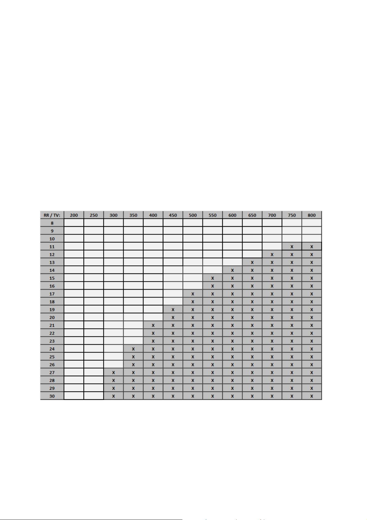
RR & TV Combinations
The SAVe II supports minute volumes of up to 8 LPM at an I:E ratio of 1:2. The cells marked
with an “X” are combinations that exceed the pump’s capabilities and therefore are not
permitted. If an operator wanted to change the settings from 500 ml at 15 BPM to 400 ml and
17 BPM (both of which are permitted) the user would first decrease the tidal volume to 400 ml
before increasing the respiratory rate to 17 BPM. Trying to increase the respiratory rate first
isn’t possible because the device does not support 17 BPM respiratory rate at a 500 ml tidal
volume.
A visual (no audible) MV HIGH alarm indicator will activate if operator selects a RR/TV
combination that results in I:E ratio of less than 1:2. If +/- controls appear to not work, it is likely
that the operator has attempted to select a RR/TV combination that is not supported. AutoMedx
recommends that the operators experiment with this during training so that it does not come as
a surprise during actual use.
TABLE 2: ALLOWED RR AND TV COMBINATIONS
SAVe II OPERATION MANUAL Page 28
Page 29

Peak Inspiratory Pressure (PIP)
The PIP LIMIT controls the maximum acceptable pressure during the Inspiratory Phase before the
pump shuts off and the PIP Reached alarm activates. When the PIP pressure limit is reached, the
pump will cutoff to prevent over inflation and the unit will enter the exhalation phase. An audible
and visual alarm indicator will active. The PIP limit is automatically set to 20 cmH2O when entering
RR is set to zero (MASK CPR Mode).
WARNING: Do not increase the preset PIP limit unless directed to do so by personnel with
the required level of training. This is very important when using a mask, LMA or supraglottic
airway devices because excessive airway pressure may direct air into the stomach causing
gastric insufflation or serious complications.
WARNING: If PIP limit is reached, the SAVe II will cut the inspiratory phase short and less TV
than indicated will be delivered to patient.
Positive End Expiratory Pressure (PEEP)
The SAVe II has the internal capability to maintain a set Positive End Expiratory Pressure (PEEP).
The device may take up to 1 minute to reach the desired PEEP level after a confirmed change. The
SAVe II is designed to safely reach targeted PEEP value by slowly incrementing PEEP with each
breath. The SAVe II may take up to a minute to reach targeted PEEP value. PEEP is disabled in
MASK CPR Mode.
WARNING: PEEP is contraindicated during CPR
D
ISPLAYING MEASURED
When settings are confirmed and no changes are pending (i.e. the Confirm Indicators are not
blinking), pressing the Confirm button will cause the most recent measured PIP and PEEP values to
be displayed for 3 seconds. During this time the RR and TV displays are cleared to help indicate
that the device is displaying measured values.
The user may revert the display back to the active ventilator settings prior to the 3 second
automatic transition by pressing the Confirm button again. The user may also begin to make
changes to the ventilator settings without returning to the active settings display; pressing a
Height Preset or “+” or ”-“ control button will be handled as normal, and will cause the device to
show the pending ventilator settings.
The PIP and PEEP measurements are taken at the patient airway at the end of their respective
breath phases. The displays show the most recently measured values prior to pressing the
Confirm button.
PIP
AND
PEEP
SAVe II OPERATION MANUAL Page 29
Page 30
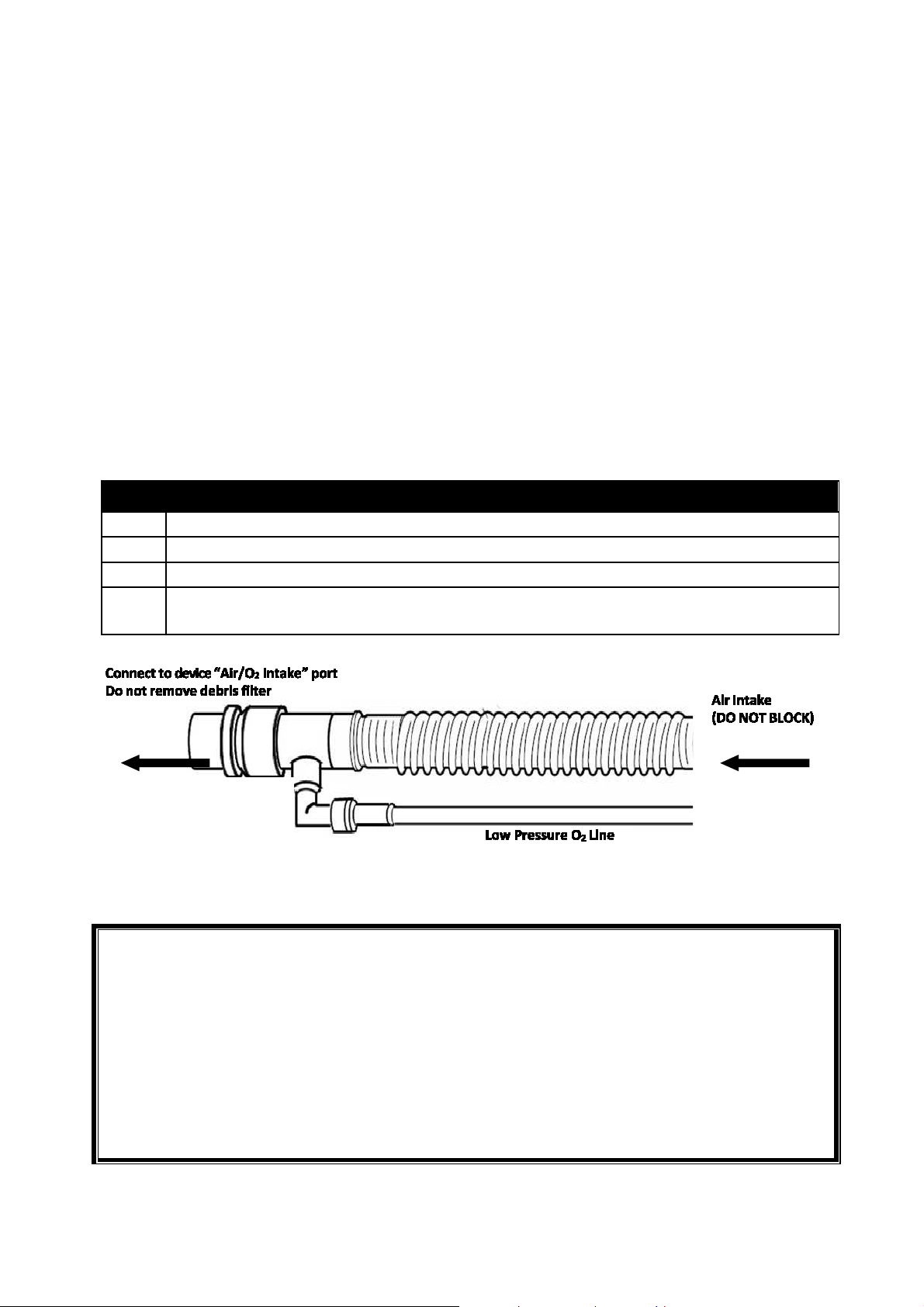
2 Attach reservoir’s green connector to “Air/ O
Intake” port then fully extend the collapsible
3 Attach reservoir
’s low pressure O
line to flow regulated oxygen source.
Set flow regulated
oxygen
source
to
deliver
between 0
–
10 LPM. Reference FiO
look up
levels in the vicinity of the leak. To avoid the risk of ignition, visually
(only those approved for oxygen use) in contact with any part of the ventilator, regulator, or
The oxygen
supply
must
be
shutoff
when
ventilation
is
interrupted.
Step 5A: Connect Supplemental Oxygen (Optional)
The reusable OXYGEN RESERVOIR (P/N: M40092) allows the SAVe II to deliver up to 100%
FiO2 using a low flow supplemental oxygen source. The reservoir avoids wasting O2 delivered
by the low flow O2 source during the device’s exhalation phase by accumulating it for delivery
in the inhalation phase. Simply connect the Oxygen Reservoir to the device as described below
and then connect the low flow line to a flow regulated oxygen tank, a low-flow wall source or
an oxygen concentrator capable of delivering between 0 and 10 LPM. Given the max minute
volume of the SAVe II is 8 LPM any additional oxygen flow would spill out of the reservoir tube
into the ambient air. The Oxyg en Reservoir will also dampen the noise produced by the
ventilator.
Do not delay therapy to connect supplemental O2. Connect reservoir tube only after the
ventilator is providing air to the patient.
Connect Low Flow Oxygen Source by:
1
4
Remove Air Intake Cap from the “Air/ O2 Intake” port. Store for later use. Do not remove
2
2
2
table below.
FIGURE 7: OXYGEN RESERVOIR
WARNING:
If using supplemental oxygen, avoid smoking or open flames. Leaks at oxygen connections
can cause dangerous O2
inspect oxygen connections before and after connecting supplemental O2 and take
measures to properly ventilate the area. Do not use oil, grease, or combustible lubricants
cylinder.
Do not block the air intake port of the O2 Reservoir.
Place end of reservoir tube in a location that will prevent sand or dust from entering.
SAVe II OPERATION MANUAL Page 30
Page 31

WARNING:
Take required precautions when using Oxygen. Do not use in explosive atmospheres or near
Minute
Volume:
2 L 3 L 4 L 5 L 6 L 7L 8L
O2 Flow
Rate:
1 60 47 40 36 33 31 30
2 100 74 60 52 46 43 40
3 100 100 80 68 59 54 50
4 100 100 100 84 74 66 60
5 100 100 100 100 87 77 70
6 100 100 100 100 100 89 80
7 100 100 100 100 100 100 90
8 100 100 100 100 100 100 100
9 100 100 100 100 100 100 100
10 100 100 100 100 100 100 100
The hose connecting the ventilator to the oxygen source must be designed exclusively for
use with medical-grade oxygen. Under no circumstances should the user modify the low
pressure O2 line. In addition, the line must be attached without the use of lubricants.
open flame.
Do not use flow rates greater than 10 LPM.
The desired FIO2 is achieved by regulating the amount of O2 delivered relative to the minute
volume being produced by the ventilator. Use Table 3 below to determine the delivered
FIO2 % based on Minute Volume (RR x TV) and oxygen supply flow rate. For instance at a
respiratory rate of 10 BPM and a tidal volume of 500 ml the device is delivering 5 LPM.
Setting the O2 source to deliver 3 LPM would result in a FIO2 of approximately 68%
(3L*100% + 2L*21%)/5LPM = 68%. The oxygen reservoir tube must be fully expanded to
achieve the O2 concentrations listed below. As a rule of thumb if you’re ventilating a
patient using any of the presets on the user interface delivering 2 LPM of O2 will result in
40-50% FIO2 and if 100% FIO2 set the flow to 6.6 LPM.
Note:
Setting the oxygen source flow rate higher than the minute volume of the ventilator will
unnecessarily deplete oxygen supply faster.
The below values are predicated on a fully expanded oxygen reservoir tube. Failing to fully
extend the tube may material decrease FiO2 values for a given O2 flowrate.
Many variables impact delivered FiO
values. If the concentration of delivered oxygen is
2
critical then it should be measured with a calibrated oxygen analyzer that features a
minimum and maximum concentration alarm.
TABLE 3: DELIVERED FIO2 % BASED ON MINUTE VOLUME AND SUPPLEMENTAL O2 FLOW RATE
Note: These values assume the O2 tank or concentrator is delivering 100%.
SAVe II OPERATION MANUAL Page 31
Page 32
the port
well.
Attenuator.
Connect
to
device
“Air/O2
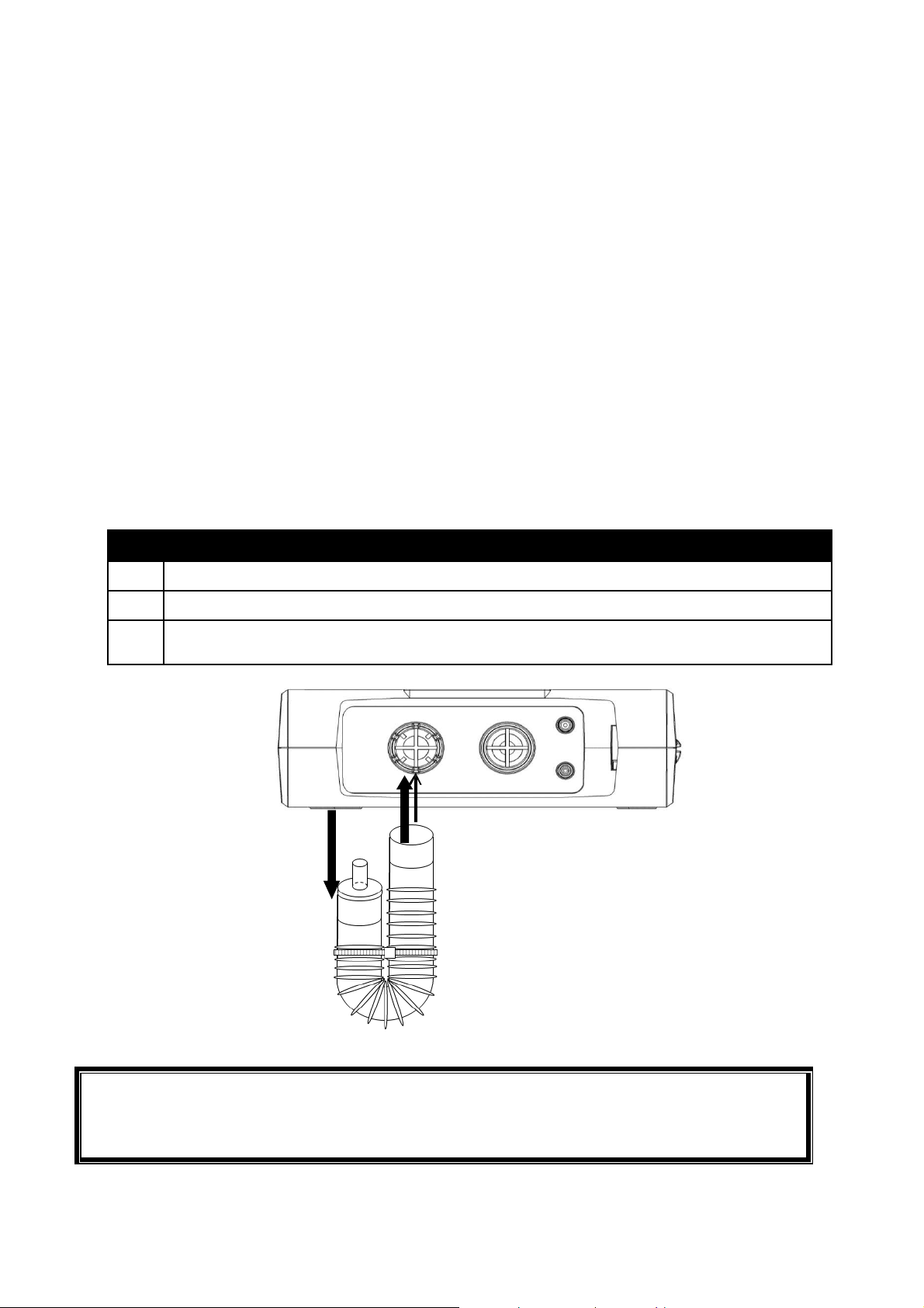
FIGURE
8:
CONNECTING
ATTENUATOR
Step 5B: Connect NOISE ATTENUATOR (Optional)
The reusable ATTENUATOR (P/N: M41112) is a U shaped tube designed to mitigate the noise of
the device. The attenuator is connected to the air intake port as shown in Figure 8. The
attenuator is meant to be U shaped. Do not cut the fastener that holds the shape.
In order to keep the SAVe II small the attenuator which mitigates the sound of the ventilator
has been developed as an external reusable accessory rather than an internal component. It is
not required for operation but can be used to significantly dampen the noise. The attenuator is
a small U shaped tube that has a small nipple on the end. Remove the black Air Intake Cap and
connect the female end of the Attenuator over the air intake port, which contains the debris
filter (do not remove the filter) and position the nipple to sit inside the port well so that it is
not easily occluded. If the nipple becomes occluded, air will not be delivered to the patient
and a disconnect alarm will trigger. Do not cut the small cord holding the attenuator in a U
shape. If the attenuator is exposed to sand or dust wash it with water between uses. Make sure
it is dry before reusing. In a dust or sand storm the black Air Intake Port Cap will do a better job
than an attenuator at guarding against particulates getting into the pump.
ATTACH ATTENUATOR BY:
1
Remove the black Air Intake Port Cap (See Figure 3) from Air Intake Port.
2
Attach the Attenuator to Air Intake Port. Leave Debris Filters in place.
3
To avoid blocking the nipple at the end of the attenuator, orient it so that it faces into
Intake” port
WARNING: Do not occlude small nipple as this will dramatically decrease tidal volume.
WARNING: In particularly sandy or dusty conditions use the Air Intake Port Cap instead of the
SAVe II OPERATION MANUAL Page 32
Page 33

Step 6: Monitor Patient and Respond to Alarms
Monitor the patient and verify adequate chest rise. Refer to information on page 37 for
information on how to respond to alarms.
Manually Triggered Breaths
The Respiratory Rate of the device can be controlled manually by pressing the MANUAL TRIGGER
button.
M
ANUALLY TRIGGERED BREATHS DURING NORMAL OPERATION
If a temporary increase in Respiratory Rate is desired during normal operation, the operator
may press the Manual Trigger Button to deliver the set Tidal Volume. To avoid stacking
breaths, the Manual Trigger button is only active during the expiratory phase of the breath
cycle. If the operator wants to only deliver manual breaths set the respiratory rate to zero.
M
ASK
CPR M
MASK CPR MODE allows operators performing MASK CPR to give the specified number of
compressions and then manually trigger breathes as directed by the American Heart Association
guidelines. In MASK CPR MODE, the PEEP and PATIENT TRIGGERED BREATHS are disabled.
The PIP LIMIT defaults to 20 cmH2O to reduce the risk of gastric insufflation (air directed to
stomach) and the COMPRESSION RATE INDICATOR and BREATH ALARM become active. To
avoid stacking breaths, the button will only trigger a breath after the minimum exhalation time has
elapsed.
ODE
Note:
Heart LED blinks at compression rate of 100 per minute.
Default PIP Limit is decreased to 20 cmH
O for all heights in Mask CPR Mode but is still
2
adjustable. This is intended to avoid air being directed to the stomach (gastric
insufflation).
If the Manual Trigger button is not pressed for 30 seconds “Breath” alarm will trigger
indicating a breath needs to be delivered.
To exit MASK CPR Mode, the user can select and confirm a height preset or non-zero
respiratory rate.
SAVe II OPERATION MANUAL Page 33
Page 34
Operator Action
Expected Device Response
1 Set tidal volume
Decrease respiratory rate
2
to zero (0)
3 Press Confirm
Press Manual Trigger to
4
deliver breath
Follow AHA Guidelines or
5
protocol as directed by
your Medical Director
WARNING:
Operators must press MANUAL TRIGGER control button for ventilator to deliver
breath.
Increasing PIP LIMIT to above 20 cmH2O when using an airway other than a properly
placed ET Tube may result in gastric insufflation.
TV indicator blinks
Manual Trigger and RR indicators blink
PEEP disabled (set to zero)
PIP defaults to 20 cmH
TV, RR and Manual Trigger lights stop
2
O
blinking
Compression rate light (heart icon) flashes at 100/min
Single breath delivered at stated settings
Device will only deliver breaths when M
T
RIG GER
B
REATH ALARM
button is pressed
indicator activates if breath not
ANU AL
delivered for 30 seconds
SAVe II OPERATION MANUAL Page 34
Page 35
Clearing Debris from Breathing Circuit
1 If an appropriate
replacement
circuit
is
available
then
replace
activ
e circuit
with
new
2 If a replacement
circuit
is
not available
then
consider
ventilating
patient
by
other
means.
4 Verify
proper
operation.
way
diaphragm properly seated.
The SAVe II Breathing Circuit is for a single patient use. If the patient aspirates during use and the
circuit needs to be cleared of debris then follow steps below.
CLEAR DEBRIS FROM BREATHING CIRCUIT BY:
circuit.
Clear debris by removing Flexible Elbow and any other piece of the circuit as
3
necessary to empty contents then reassemble and verify proper orientation. (See Figure
9)
5 Reattach circuit to patient. Verify adequate chest rise and monitor pulse oximeter if
available.
WARNING:
FIGURE 9: CLEANING A PATIENT BREATHING CIRCUIT
Operators must verify Breathing Circuit has been reassembled correctly.
If the Demand Valve is removed or modified it MUST be reassembled with the one-
valves oriented in the correct direction.
Verify the Control Valve cap (connected to Control Line) is securely attached with the
SAVe II OPERATION MANUAL Page 35
Page 36

Alarm Overview
The SAVe II has a number of alarms to alert the operator to potentially unsafe conditions.
These alarms trigger by monitoring internal device parameters and airway pressures.
The device will continue delivering breaths during most alarms; however, if it detects a
condition that may cause direct harm to the patient by delivering another breath, the device
will enter a safe mode and stop delivering breaths until the problem is resolved. Once the
problem is resolved, the device will resume normal operation.
When an Alarm condition occurs:
•
A Visual Alarm indicator flashes on and off and an Audible Alarm sounds (except the MV
HIGH Alarm which is strictly a visual alarm).
•
Depending on the alarm, the SAVe II may take other actions, such as terminating an
inspiration or opening the exhalation valve.
•
Pressing Mute will silence the Audio Alarm for 120 seconds.
When an Alarm condition clears:
•
The A
•
The V
UDIBLE ALARM
ISU AL ALARM
ceases.
indicator stops flashing and turns solid for 30 seconds after which the
indicator turns off.
WARNING: Failure to respond to alarms can result in serious harm or death. Alarms should
always be monitored and the operator should be prepared to ventilate with alternative method
of ventilation.
WARNING: The absence of an alarm does not indicate the patient is receiving adequate
ventilation. If the SAVe II is used for extended periods, it is recommended the operator monitor
blood gases to ensure adequate gas exchange.
To help operators prioritize multiple simultaneous alarms, the Audible Alarm indicator of the
SAVe II is divided into three levels of priority. The easiest way to distinguish between the
priorities is how quickly the alarm repeats. The high priority alarms repeat every 2.5 seconds.
SAVe II OPERATION MANUAL Page 36
Page 37

LEVEL
AUDIBLE CHARACTERISTICS
ALARMS
Disconnect
Beep, Pause 100ms, Beep, Pause
High
100ms, Beep, Pause 300ms, Beep,
Pause 100ms, Beep, Pause 500ms….
Repeats every 2.5 seconds
Beep, Pause 200ms, Beep, Pause
Medium
Low
200ms….
Repeats every 7.5 seconds
Beep, Pause 200ms…
Repeats every 20 seconds
Alarm Quick Reference Guide
ALARM
CAUSE/TRIGGER
RESOLUTION
PIP Reached
Device
High PEEP
Battery < 5% capacity
Breath
Breath Assist
Battery <10% capacity
Battery <15% capacity
DEVICES RESPONSE
Disconnect
Inadequately
connected circuit
tubing
Inadequate seal
between patient
and airway
Blocked Intake Port
or Attenuator
Leak in Patient
Breathing Circuit
Dust, sand or debris
inside device manifold
Pressure > 1 cmH2O/110 ml
of TV at end of inhalation
AND
Pressure increase during
last 250ms of inhale is >=
1cmH2O/120ml (only when
inhale flow rate is > 14Lpm
and end inspiratory
pressure is < 5cmH2O)
High Priority Alarm
Continues to deliver breaths
SAVe II OPERATION MANUAL Page 37
Page 38

High Priority Alarm
Connect
the
device
to
At 15%
of capacity last
ALARM
PIP
Reached
Battery
CAUSE/TRIGGER
Patient airway
pressure reached Peak
Inspiratory Pressure
Limit during inhalation
Various low
battery
thresholds (see
Battery Indicator
section)
RESOLUTION
DEVICES RESPONSE
Full inhalation of the
patient without reaching
set PIP limit. Usually
requires operator to
increase PIP Limit or
decrease tidal volume. To
maintain constant minute
Enter exhalation phase
when pressure limit
reached
Continues to deliver
breaths
volume offset any decrease
in TV by increasing
respiratory rate.
approved external battery
charger
battery LED begins to flash.
Low Priority Alarm for 30
seconds.
At 8% of capacity Medium
Priority Alarm for 30
seconds
At or below 5% of
capacity High Priority
Alarm for 30 secs
At 0% of capacity (running on
Reserve Capacity) device will
go into Low Battery Mode:
- Discontinue breaths
- Open Exhalation Valve
- Therapy control indicators
are cleared
All button presses (except
mute and power) are disabled
The high priority audible alarm
will sound.
SAVe II OPERATION MANUAL Page 38
Page 39

ALARM
DEVICES RESPONSE
Device
High
PEEP
MV
High
30
seconds
has
Breath
Measured Airway
None
CAUSE/TRIGGER RESOLUTION
Device is outside of
allowable temperature
range
OR
Internal malfunction
Measured PEEP > 5
cmH2O
PEEP
above set
A TV or RR
increment button is
pushed to a TV/RR
combination that is
not permitted
Turn off unit and then back
on. If the condition that
triggered the alarm is still
present, the alarm will
reactivate.
Refer to Device Alarms on
page 43
Measured PEEP < 2 cmH2O
above set
PEEP level
The device settings will not
allow the selected TV or RR
to change
If changing TV & RR start
with the one which is
decreasing
High Priority Alarm
Opens exhaust port
Discontinues Ventilation
High Priority Alarm Open
exhaust port
Discontinue breaths until
condition cleared
MV High Visual
Alarm No
Audio Alarm
Will not allow TV/RR
combination
Breath
(Manual)
elapsed since last
manually triggered
breath when RR is set
to 0 (MASK CPR
Mode)
Manually trigger a
breath
OR
Increase RR to non-zero
value
High Priority Alarm
“Breath” alarm indicator
activates
“Breath Assist” alarm
Assist
Pressure > 2
cmH2O
below set PEEP
(Patient is
spontaneously
breathing)
indicator activates.
Patient’s inspiratory effort
immediately triggers breath
Deliver set TV at max pump
flow rate
SAVe II OPERATION MANUAL Page 39
Page 40

R
ESPONDING TO ALARMS
DISCONNECT ALARM
The Disconnect Alarm indicates the minimum pressure threshold has not been reached during
the Inspiratory Phase of the ventilator. The ventilator will continue to operate and alarm until
the condition is resolved.
Triggered when Airway Pressure is <1cmH2O/110 ml of TV at end of inhalation or pressure
increase during last 250ms of inhale is < 1cmH2O/120ml (only checked when inhale flow is >
14LPM and end inspiratory pressure < 5cmH2O).
Device responds by:
Activating DISCONNECT visual alarm indicator and high priority audible alarm indicator
Device will continue to actively ventilate
WARNING:
The absence of an alarm does not indicate the patient is receiving adequate
Failure to respond to alarms can result in serious harm or death. Alarms should
POSSIBLE CAUSE
Inadequately connected
circuit tubing
Inadequate seal between
patient and airway
Blocked Intake Port or
Attenuator
Leak in Patient Breathing
Circuit
ventilation. It is recommended the operator monitor blood gases to ensure
adequate gas exchange.
always be monitored and the operator should be prepared to ventilate with
alternative method.
WHAT TO DO
1. Verify Breathing Circuit tubing connections
between SAVe II control unit and airway.
2. Verify mask or airway is tightly sealed to
patient. Adjust seal pressure if necessary.
3. Verify nothing is blocking the device air
intake which could prevent device from
drawing in ambient air.
4. Replace Breathing Circuit (if available).
5. Ventilate by alternative means.
Dust, sand or other debris
inside device manifold
6. If 4 and 5 are not possible, listen/feel
Breathing Circuit for leaks. Patch leak if
found.
Resolved when measured pressure is > 1 cmH2O/110 ml of TV at end of inhalation AND
pressure increase during last 250ms of inhale is >= 1cmH2O/120ml (only when inhale flow rate
is > 14Lpm and end inspiratory pressure is < 5cmH
2
O)
SAVe II OPERATION MANUAL Page 40
Page 41

PIP REACHED ALARM
The PIP REACHED alarm will activate if the pressure measured at the patient airway exceeds the
PIP Limit setting. When this alarm occurs, any inspiration in progress is terminated and the
Exhalation Valve is opened. Except in MASK CPR MODE, the next breath will begin after the
appropriate expiration time has expired. In MASK CPR MODE, the next breath will initiate
when the operator presses the MANUAL TRIGGER button. The alarm is resolved when a full
breath is delivered without reaching the set PIP Limit.
Device responds by:
Activating PIP REACHED visual alarm and high priority audible alarm
Entering exhalation phase (cycling) when set pressure limit is reached
WARNING:
If PIP limit is reached, the SAVe II will cut the inspiratory phase short and less than the
stated TV will be delivered to patient.
Failure to respond to alarms can result in serious harm or death. Alarms should always
be monitored and the operator should be prepared to ventilate with alternative
method of ventilation.
POSSIBLE CAUSE
Kinked Breathing Circuit
Blocked airway
Low patient lung compliance
High patient airway resistance
Vomitus in airway
Tension pneumothorax
Patient is actively exhaling during the
inspiratory phase of the device (may
be accompanied by Breath Assist
and/or HIGH PEEP alarm)
WHAT TO DO
1. Verify Breathing Circuit does not have
kinks.
2. Verify correct placement of airway and
that it is clear of obstructions. (See Page
33 for instructions on clearing debris).
3. Verify PIP limit and TV setting are
appropriate. To maintain Minute
Volume consider offsetting any decrease
in TV by increasing the respiratory rate.
4. Verify patient does not have a tension
pneumothorax.
5. Disconnect Breath Circuit from the
patient airway. If alarm condition
continues (blinking PIP REACHED
indicator) then take the device out of
service.
SAVe II OPERATION MANUAL Page 41
Page 42

BATTERY ALARM
The BATTERY alarm activates when less than 10% of battery capacity remains. To resolve the
alarm connect to an appropriate external power source.
Device response:
At 10% of capacity:
o Low Priority audible indicator activates for 30 seconds
o Last battery LED begins to flash
At 8% of capacity:
o Medium Priority audible indicator activates for 30 seconds
o Last battery LED continues flashing
At or below 5% of capacity:
o High Priority audible indicator activates for 30 second
o Last battery LED continues flashing
At or below 0% of capacity (Reserve Capacity):
o Device will go into Low Battery Mode for 5 minutes:
Discontinue breaths
Open Exhalation Valve
Therapy control indicators are cleared
Alarm continues to sound
All button presses (except mute and power) are disabled
POSSIBLE CAUSE
The battery charge has been
depleted
Battery has been stored for
extended periods at high
temperatures.
WHAT TO DO
1. Connect device to an external power
source using SAVe II AC Power
Supply.
2. Prepare to ventilate by alternative
means if an external power source is
not available.
Battery has reached the end of
its useful life
Note: If the battery is disconnected, ONLY the Hazard indicator will illuminate and the audible
alarm will sound for at least 2 minutes until all power reserves are drained.
3. Verify that the battery has been
maintained properly. Refer to
information on page 45.
SAVe II OPERATION MANUAL Page 42
Page 43

DEVICE ALARM
WHAT TO DO
The SAVe II software monitors multiple components to ensure they are operating within expected
parameters. The Device Alarm is triggered when device is outside of specified temperature range
OR a non-field correctible malfunction is detected.
Device responds by:
Activating DEVICE visual alarm indicator and high priority audible alarm indicator.
Stops ventilating (cycling)
Opens the Exhaust Valve to allow patient to spontaneously breath with minimal resistance
Displays a Device error code in the tidal volume (TV) Display
If an error code is observed turn the device off then on to clear transient alarms. If this does not
address the problem begin ventilating using another method.
See if the error code corresponds to one of the following potentially field correctable issues:
E13 – Most likely caused by operating at temperatures below -10C. Increase device
temperature to above 0C.
E15 – Most likely caused by a loose battery connection or battery that has entered a safe
mode due to a malfunction. Verify the battery connection. If the device still produces error
code, then replace battery.
E16 – Most likely caused by operating at temperatures above 60C. Decrease device
temperature to below 50C.
For all other device codes or if the error is not field correctable then immediately take the device
out of service. Make a note of the error code and contact an authorized service provider.
HIGH PEEP ALARM
Alarm is triggered when measured PEEP is 5 cmH2O above set PEEP. Alarm is resolved when
measured PEEP is < 2 cmH2O above set PEEP level.
POSSIBLE CAUSE
Exhalation Port blocked
Patient not synchronizing with
ventilator
1. Clear blockage from Exhalation Port.
2. Adjust RR or consider manually trigger
breaths
3. If Patient is spontaneously breathing
consider sedating patient or stopping
ventilation as directed by medical
director.
4. Disconnect Breath Circuit from the
patient airway. If alarm condition
continues take the device out of service.
SAVe II OPERATION MANUAL Page 43
Page 44

MV HIGH ALARM
The combination of TV/RR requires a flow rate that exceeds the pumps ability to deliver at an I:E
ratio of 1:2. The device will not permit operator to select these TV/RR combinations. Refer to
information on page 27.
POSSIBLE CAUSE
Attempted to select RR &
TV combination that
would have resulted in a
minute volume greater
than 8 LPM
BREATH ALARM
POSSIBLE CAUSE
Device is in MASK CPR mode (RR = 0)
and 30 seconds have elapsed since
last manually triggered breath
WHAT TO DO
1. Select TV/RR combination that results in minute
volume of no more than 8 LPM see Table 2.
2. If one parameter is being adjusted up and the
other down, start by adjusting the parameter
moving down. For instance, if moving to higher
respiratory rate (10 16 BPM) and lower
volume (600 400 ml), reduce TV before
increasing RR. Otherwise the device will not let
you increase the RR beyond 13 BPM because
that is the highest rate supported at 600 ml.
WHAT TO DO
1. Press MANUAL TRIGGER if a breath
2. Increase RR above 0 to exit MASK
is indicated.
CPR mode if indicated.
BREATH ASSIST ALARM
POSSIBLE CAUSE
Patient inspiratory effort was
detected (spontaneous breathing)
and triggered breath assist
CPR chest compressions have
triggered breath assist
SAVe II OPERATION MANUAL Page 44
WHAT TO DO
1. If patient is not synchronizing with
2. If performing chest compressions,
ventilator, consider removing patient
from ventilator if patient is able to
breathe adequately.
consider putting the ventilator into
MASK CPR Mode.
Page 45
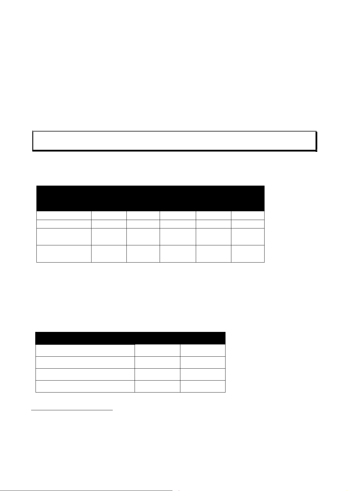
MAINTENANCE
PROCEDURE
USE
USE
LY
Charge
x x x x x
Functionality
Maintenance Schedule
Battery Maintenance
Cleaning
Replace Consumables
Storage
Scheduled Maintenance
WARNING: Failure to follow maintenance instructions could result in damage to the ventilator. This could
reduce the life of the unit or lead to potential harm to the patient.
Maintenance Schedule
The SAVe II ventilator is designed to operate with minimal maintenance. However, the device
should be annually calibrated by an authorized service representative.
PERFORMED BY: WHEN:
MEDIC
Clean x
Verify
BMET
x
x
x
BEFORE
x
AFTER
ANNUAL
x
x
x
Verify
Performance
x
x
Battery Maintenance
Runtime on a single battery charge depends on multiple factors: Tidal Volume, Respiratory Rate,
PEEP, patient compliance, environmental temperature, number of charge/discharge cycles,
previous storage conditions, depth of discharge and age of battery.
When a new battery is fully charged, the SAVe II will run for 10 hours when set to 500 ml and 10
BPM.1
BATTERY CHARGE RETENTION
1 Month
3 Months
6 Months
12 Months
1
Test conditions: Lung Resistance 5 cmH2O/L/sec., Compliance 0.02 L/cmH2O, Settings: Respiratory rate 10, Tidal Volume
500 ml, Peak Inspiratory Pressure 40 cmH2O, PEEP 0 cmH2O, at room temperature and humidity on a 2400mAh battery is
10 hours and on the 2800 mAh battery 12 hours.
21°C (70°F)
97%
94%
93%
90%
45°C (113°F)
92%
87%
83%
76%
SAVe II OPERATION MANUAL Page 45
Page 46

All batteries degrade over time. The below chart shows you how much of the battery’s potential
can be recovered after a period of storage. If the battery will be stored at high temperatures store
with 50% charge.
CHARGE RECOVERED
Storage Temperature
21°C (70°F)
45°C (113°F)
100% STORAGE CHARGE
6 Months
98%
92%
12 Months
96%
87%
50% STORAGE CHARGE
6 Months
99%
97%
12 Months
99%
97%
CLEANING
Keep the SAVe II and its accessories clean at all times. The SAVe II ventilator should never be
disassembled in the field. The following components may be cleaned as needed between uses:
• Control Unit
• O
Reservoir
2
• Attenuator
• Carrying Case
C
ONTROL UNIT
All SAVe II external surfaces should be cleaned before and after each patient use and as may
be required. Wipe the exterior surfaces of SAVe II (including the inside of the port cover) with a
clean, damp cloth. The use of methylated spirits is acceptable. Be sure to wipe away any
residual cleaner. See caution statement regarding cleaning agents.
Do not clean any portion of the SAVe II or its accessories with abrasives or chlorinated
hydrocarbon cleansers.
Do not allow dirt, sand, debris, grease, oil, or caustic chemicals to enter or coat, the unit
or its accessories. To prevent debris from entering the SAVe II, the DEBRIS FILTERS should
always be securely in place and the PORT COVER should be closed when the unit is not in
use. If the debris filter becomes saturated with dust or sand turn the unit upside down
when removing the filter so any loose debris falls out rather than in the unit. If sand or
dust gets into the unit, service the unit before using as particulates may significantly
impact tidal volume.
Clean the port well and port cover prior to removing the Debris Filter.
It is recommended the SAVe II be stored in its carrying case when not in use.
WARNING: Sand or dust inside the pump may significantly decrease the volume delivered to the patient.
SAVe II OPERATION MANUAL Page 46
Page 47

Single-Use Accessories – Do not attempt to clean or re-use single use accessories.
Outside Accessories – Refer to accessories instructions for use for cleaning procedures.
Cleaning Agents – To avoid damaging SAVe II plastic components and User Interface, do not
use cleaning agents containing ammonium chloride, other chloride compounds, more than 2%
glutaraldehyde, phenols, or abrasive cleaners.
Immersion – Under no circumstances should the SAVe II or its accessories be immersed in
liquid. If the SAVe II becomes wet, the unit should be dried using a lint-free cloth
immediately, or once the unit is no longer in use. If the SAVe II becomes immersed,
discontinue use and return to appropriate service facility for inspection. DO NOT expose the
switch, external power jack, or audible alarm port directly to liquids.
Auto-Clave – Never expose to an autoclave.
R
EPLACE CONSUMABLES
The following SAVe II Accessories are intended for use on a single patient and should be replaced
following each use:
• Patient Breathing Circuit
• Debris Filter
• Mask (If used)
WARNING: Serious harm to the patient may result from the use of unauthorized parts or accessories. To ensure
proper performance of the ventilator, only use accessories approved by AutoMedx.
WARNING: Serious harm to the patient may result from the use of unauthorized parts or accessories. To ensure
proper performance of the ventilator, only use accessories approved by AutoMedx.
BREATHING CIRCUIT
The SAVe II Breathing Circuit is single use. Examine the Breathing Circuit tubes for cracking,
discoloration, sharp edges, or other signs of damage. DO NOT attempt to use or repair
damaged Breathing Circuits. Damaged Breathing Circuits must be replaced. If necessary,
exterior walls of tubing may be cleaned with a damp cloth and dried using a lint-free cloth.
DEBRIS FILTER
The debris filter should be replaced with a new filter following each use. If the debris filter
becomes damaged or soiled during use, replace it with a new debris filter and reattach Intake
Port Cap, Attenuator or O2 Reservoir. If the debris filter is soiled remove the filter while the device
is upside down so that any loose debris falls out instead of in the unit. If sand or dust get past the
debris filter discontinue use and have it serviced.
SAVe II OPERATION MANUAL Page 47
Page 48
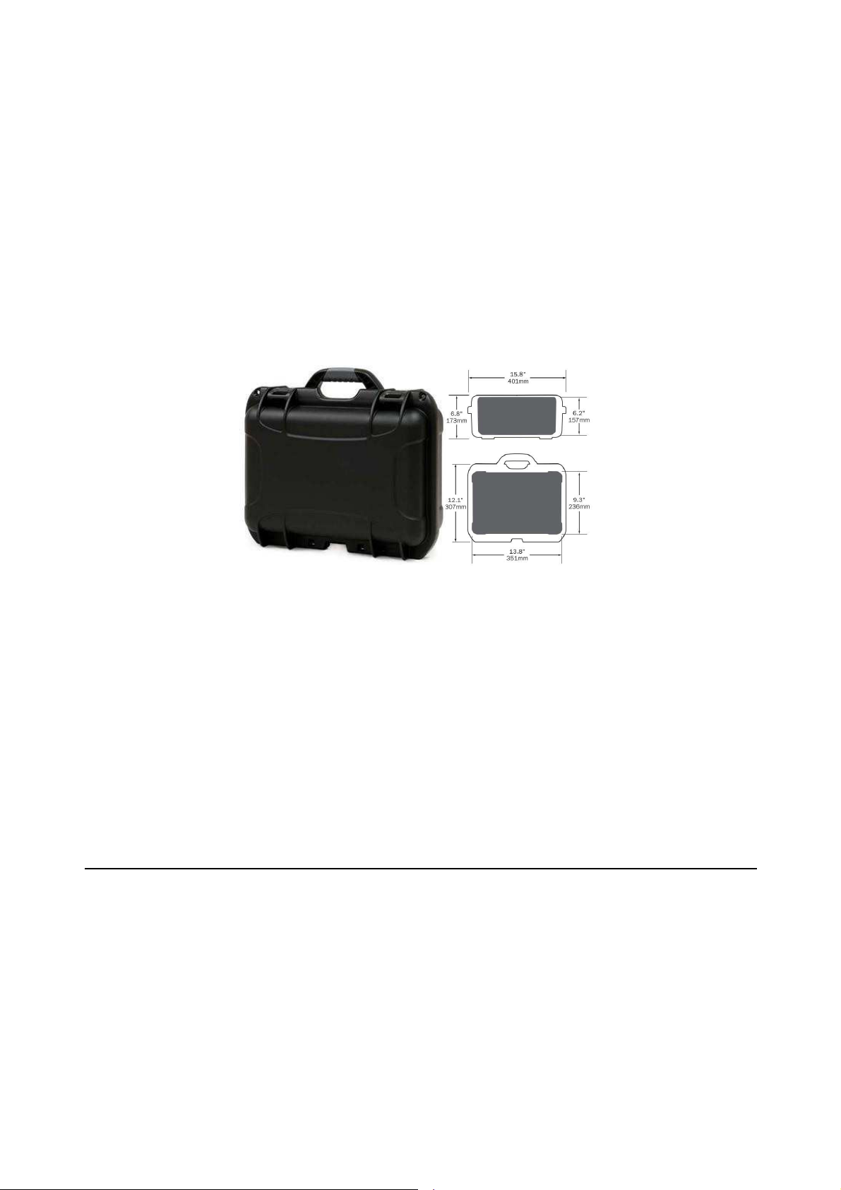
MASK
The mask included in the SAVe II Kit (P/N: 70100) should be replaced following each use.
S
TORAGE
The SAVe II should be stored as a complete kit in a state of readiness. AutoMedx recommends
storing in the device’s hard case which is water, dust and sand proof. The SAVe II CARRYING
CASE (P/N: F20055) is designed to protect the SAVe II and its accessories during transport,
shipping overseas and storage especially in sandy, dusty or wet environments. This case is rated
IP67 indicating complete protection from dust and protection from immersion in water up to 1
m. In addition, the case is designed to float to avoid immersion.
FIGURE 10: CARRYING CASE
For short-term storage, the temperature can range from 0 to 40°C (32 to 104°F).
For extended storage periods, the SAVe II should be stored indoors, out of direct sunlight, and in a
clean environment. The best storage temperature is between 10 and 30°C (50 to 80°F). The
relative humidity in the storage facility should be low.
If the device will be stored for more than 6 months at temperatures above 21°C (70°F) then the
battery should be stored at a state of charge of 50% or less to maintain a higher level of
recoverable charge. The storage state of charge is most important when the device will be
exposed to high temperatures for extended durations.
S
CHEDULED MAINTENANCE
Automedx recommends performing service annually to verify the device continues to operate
within specification. If the device is used in Extreme Environments or is exposed to dust, sand or
water then maintenance should be performed more frequently.
SAVe II OPERATION MANUAL Page 48
Page 49
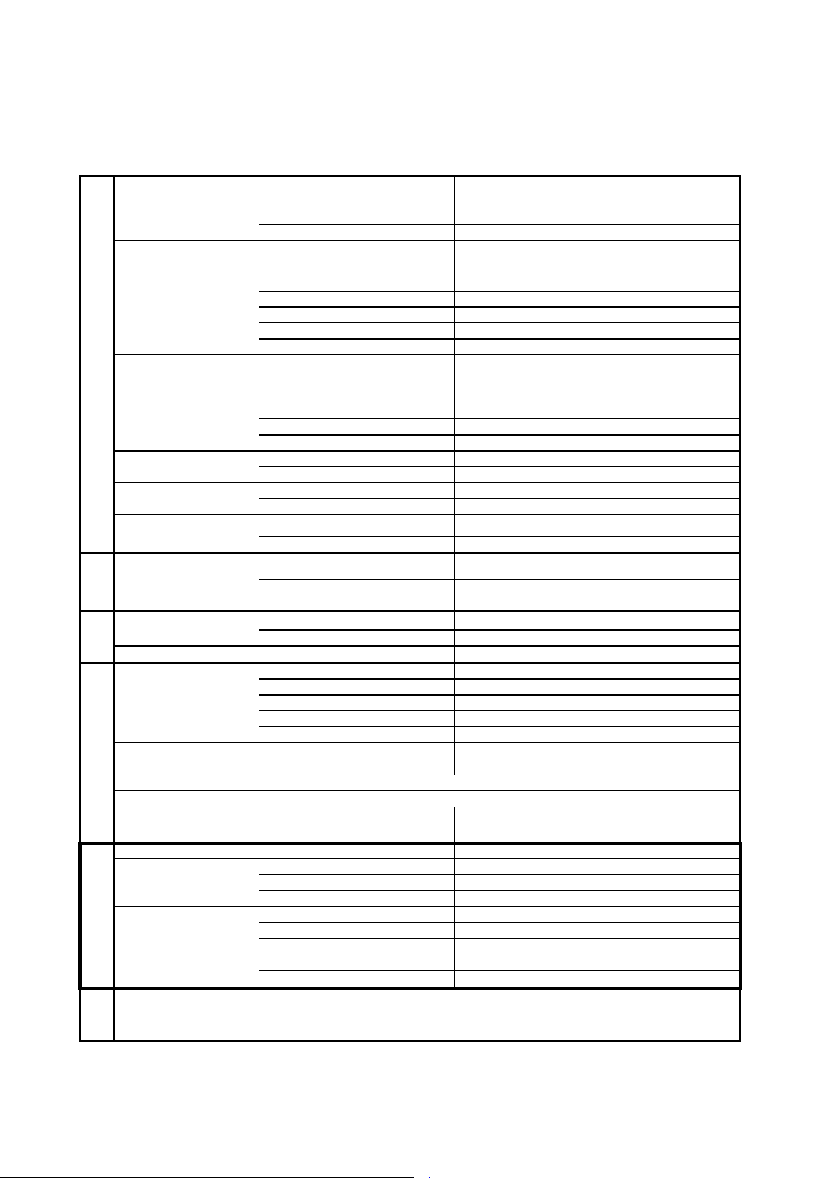
A
Secondary Control:
Pressure
Values
Operating
– Normal:
0 to
50°C (32 to 122°F)
Storage
-
Short-Term: 0 to 40°C (32 to 104°F)
Audible
Alarm
Meets 60601-1-8 IEC Standard
1 year
Change to higher capacity battery was made in July 2016. The 5’9” preset will run approximately 10 hours with the new battery
.
PPENDIX A– SPECIFICATIONS
Operating Modes: Continuous Mandatory Ventilation (CMV)
Primary Control: Time
1
Rate
Pressure (cmH2O)
Volume (ml)
Time (Seconds)
Ventilator Parameters
Resistance (cmH2O)
Supplemental Oxygen
Operating Time3:
Pressure
Measured
External Battery Charger
Power
Control Unit Input: 16.8 VDC @ 0.9A
Breath Target: Volume
Flow Rate (LPM): Up to 24
Breath Rate (BPM):
Peak Inspiratory Pressure (PIP) Limit
Positive End Expiratory Pressure (PEEP) 0 - 10 (±2cmH2O)
Inspiratory Trigger Pressure 2
Inadvertent PEEP < 2
Sensor Range -60 to +60
Tidal Volume 200 – 800
Minute Volume 1600 – 8000
Dead Space < 100
Inspiratory 0.67 – 2.50
Expiratory 1.30 – 5.00
I:E Ratio 1:2
Inspiratory
Expiratory
Input Flow Rate: 0 – 10 LPM
FIO2: 21-100%
TV=500, RR=10, PEEP=0 2400 mAh battery 10 hours | 2800 mAh battery 12 hours
TV=600, RR=10, PEEP=0 2400 mAh battery 8.5 hours | 2800 mAh battery 10 hours
Peak Inspiratory Pressure (PIP) 0 – 60 (±2 cmH2O, or 10%)
Positive End Expiratory Pressure (PEEP) 0 – 60 (±2 cmH2O, or 10%)
Input: 100 – 240 VAC / 50-60 Hz
Output (Li-Ion charger): 16.8 VDC @ 0.9A
< 6.0 cmH2O/L/sec
< 6.0 cmH2O/L/sec
8 – 30
10 - 60
Temperature Ranges
Humidity
Environmental
Atmospheric Pressure 700 – 1100 hPa
Shock & Vibration IEC 60068-2-6 and 60068-2-36
Ingress
Dimensions:
Other
Product Life
Warranty:
1
All spec if i cat i ons include a tolerance of ±10% of nominal value unless stated otherwise. Test conditions available upon request.
2
Delivered Tidal Volume may be materially affected by very low lung compliance (< 0.01 L/cmH2O)
3
Footnote
Operating – Extreme:
Storage - Long-Term: 0 to 30°C (32 to 86°F)
Charging 0 to 45°C (32 to 113°F)
Operating: 15% – 95% RH (non-condensing)
Storage: 15% to 85% RH (non-condensing)
Unit only without protection IP24
Within Hard Case IP67
Size: 6.5" x 6.25" x 2.0" (81 in3)
Weight (Unit Only): 2.6 lbs. (1.2 kg)
Weight (Kit with Hard Case) 9.7 lbs. (4.4 kg)
Control Unit 5 years
Breathing Circuit 1 year
Other Accessories See accessory labeling
Device
Battery
-10 to 50°C (23 to 122°F)
3 years
SAVe II OPERATION MANUAL Page 49
Page 50
Protection/Insulation
class
(electric
shock)
Class
II
Medical
device
directive
classification
Class
IIb
Degree
of
protection
against
risk of electric
BF
Power
External
(AC – mains)
or
internal
(DC – battery)
Operation
mode
Continuous
Operation
Emissions
Test
Compliance
Electromagnetic
Environment
–
Guidance
RF Emissions
CISPR
11 Class
B
A
PPENDIX B – REGULATORY INFO/CLASSIFICATION/ LIMITED WARRANTY
E
LECTROMAGNETIC EMISSIONS AND IMMUNITY
Guidance and Manufacturer’s Declaration – Electromagnetic Emissions
The SAVe II Portable Ventilator is intended for use in the electromagnetic environment
specified below. The customer or the user of the SAVe II Portable Ventilator should assure
that it is used in such an environment.
The SAVe II uses RF energy only for its internal function.
RF Emissions CISPR 11 Group 1
Therefore, its RF emissions are very low and are not
likely to cause any interference in nearby electronic
equipment.
Harmonic Emissions
IEC 61000-3-2
Voltage Fluctuations
/ Flicker Emissions
Class B
Complies
The SAVe II is suitable for use in all establishments
including domestic and those directly connected to the
public low-voltage power supply network power supply
that supplies buildings used for domestic purposes.
SAVe II OPERATION MANUAL Page 50
Page 51

Guidance and Manufacturer’s Declaration – Electromagnetic Immunity
The SAVe II Portable Ventilator is intended for use in the electromagnetic environment
specified below. The customer or the user of the SAVe II Portable Ventilator should
assure that it is used in such an environment.
Immunity Test
Electrostatic
Discharge (ESD)
IEC 61000-4-2
Radiated RF IEC
61000-4-3
Conducted RF IEC
61000-4-6
Electrical fast
transient IEC
61000-4-4
Surge IEC
61000-4-5
IEC60601 Test
±6kV Contact
±8kV Air
20 V/m 80MHz
to 2.5GHz
3Vrms 150kHz
to 80MHz
±2kV power
±1kV I/O lines
Differential
±2kV common
Level
line
±1kV
Compliance
Level
Complies
Complies
Complies
Complies
Complies
Electromagnetic Environment - Guidance
Floors should be wood, concrete, or
ceramic tile. If floors are covered with
synthetic material, the relative
humidity should be at least 30%.
Field strengths outside the shielded
location from fixed RF transmitters, as
determined by an electromagnetic sit
survey, should be less than 3 V/m.
Interference may occur in the vicinity
of equipment marked with the
following symbol:
Mains power quality should be that of a
typical commercial or hospital
environment.
Power frequency
magnetic field IEC
61000-4-8
Complies
3 A/m
Power frequency magnetic fields should
be at levels characteristic of a typical
location in a typical commercial or
hospital environment.
Voltage dips,
short interrupts
and voltage
variations on
power supply
input lines
IEC 61000-4-11
>95% dip 0.5
cycle
60% dip 5
cycles
70% dip 25
cycles
95% dip 5 sec.
Complies
Mains power quality should be that of a
typical commercial or hospital
environment. If the user of the SAVe II
requires continued operation during
power mains interruptions, it is
recommended that the SAVe II be
powered from an uninterruptible power
supply or battery.
SAVe II OPERATION MANUAL Page 51
Page 52

LIMITED WARRANTY
Limited Warranty Applicable to the SAVe II
AutoMedx warrants to the original purchaser (“Customer”) of the SAVe II that if there is a
defect in material or workmanship in the SAVe II and AutoMedx is notified of such defect
within three (3) years of Customer’s original purchase, AutoMedx shall, in its sole and
absolute discretion, repair or provide a replacement of such defective part(s) at no charge to
the Customer, provided that this warranty provision is not applicable to batteries or used
consumables.
Limited Warranty Applicable to the Battery
The life of the battery, as noted above, is materially affected by many factors. As such,
AutoMedx warrants to the Customer of the SAVe II that, if there is a defect in material or
workmanship in the battery contained in the SAVe II and AutoMedx is notified of such
defect within one (1) year of Customer’s original purchase, AutoMedx shall, in its sole and
absolute discretion, repair or provide a replacement of such defective battery at no charge to
the Customer.
Sole Remedy
The sole remedy for a defect in materials or workmanship of the SAVe II (or the battery or
any other component of the SAVe II) shall be, at AutoMedx’s sole and exclusive discretion,
repair or replacement of the defective SAVe II or component thereof, as the case may be.
Exclusions
AutoMedx’s warranty shall not apply to defects or conditions resulting from: (a) repairs by an
unauthorized party; (b) improper maintenance; (c) modifications made without written
permission of AutoMedx; (d) damage by accident, abuse, misuse, or misapplication; or (e)
operation otherwise than in accordance with this manual or other instructions furnished by
AutoMedx.
AutoMedx’s warranty shall not apply if the unit has been disassembled.
AutoMedx’s warranty shall not apply to: (a) any Product if the serial number of such Product has
been altered, defaced or removed or (b) any used consumables.
AutoMedx’s warranty is neither assignable nor transferable. All warranty repairs shall be subject
to return postage billing.
Disclaimer of Warranty and Limitation on Remedies
THE WARRANTY AND REMEDIES SET FORTH ABOVE ARE EXCLUSIVE AND IN LIEU OF ALL OTHERS,
WHETHER ORAL OR WRITTEN, EXPRESS OR IMPLIED. AUTOMEDX SPECIFICALLY DISCLAIMS ANY
AND ALL IMPLIED WARRANTIES, INCLUDING WITHOUT LIMITATION, WARRANTIES OF
MERCHANTABILITY AND FITNESS FOR A PARTICULAR PURPOSE.
SAVe II OPERATION MANUAL Page 52
Page 53

AUTOMEDX IS NOT RESPONSIBLE FOR DIRECT, INDIRECT, SPECIAL, INCIDENTAL,
CONSEQUENTIAL OR EXEMPLARY DAMAGES WHETHER BASED ON CONTRACT, TORT, OR ANY
OTHER LEGAL THEORY.
Limited Liability
To the maximum extent permitted by applicable law, in no event shall AutoMedx or its Suppliers
be liable for any special, incidental, indirect, physical or consequential damages whatsoever
arising out of the use or inability to use the SAVe II product and or accessories. In any case,
AutoMedx’s entire liability shall be limited to the amount actually paid for the purchase of the
SAVe II product. Valid proof of purchase required.
Disclaimer
Some countries, states, or provinces do not allow the exclusion or limitation of implied warranties
or the limitation of incidental or consequential damages for certain products supplied to
consumers, or the limitation of liability for personal injury, so the above limitations and
exclusions may be limited in their application to you. When the implied warranties are not
allowed to be excluded in their entirety, they will be limited to the duration of the applicable
written warranty. This warranty gives you specific legal rights, which may vary depending on local
law.
No part of this document may be reproduced or transmitted in any form or by any means,
electronic or mechanical, for any purpose, without the express written permission of
AutoMedx, LLC. Under the law, reproducing includes translating into another language or
format.
The information contained in this manual is applicable to the product with which it was shipped.
Product specifications and features are subject to change without notice.
SAVe II OPERATION MANUAL Page 53
Page 54

A
PPENDIX C – PRINCIPLES OF OPERATION
The SAVe II is a completely self-contained, small, light-weight, r ec h a r g e ab l e battery
powered device intended to provide controlled, positive pressure ventilation to a patient. It is a
time cycled pressure limited volume targeted ventilator. The SAVe II will monitor the patient’s
airway pressure and provide alarms for key events such as but not limited to: disconnect, high
pressure, and device malfunction. The SAVe II uses a single-patient-use breathing circuit to
connect to the device on one end and to the patient interface on the other end. The breathing
circuit on the patient end uses an industry standard 15/22 mm connector to facilitate connection
with an appropriate breathing mask, airway, or tracheal (breathing) tube. On the ventilator end,
the breathing circuit has 3 connections: 1) The main tube to deliver air to the patient; 2) The
pressure line to monitor the patient pressure; and 3) the control line to activate the exhaust port.
The SAVe II user interface is intended to provide as few user interactions as possible. Quick
selection buttons are organized in an arc-shaped graphic which allows quick selection of
appropriate default ventilator settings based on the patient’s height, ranging from 4’3” to 6’3”.
After selecting the patient’s height, pressing the Confirm button will start the device in
“Ventilation” mode. This “Adult Presets” section is intended both for Basic Users as well as
making initial setup minimal. When desired an Advanced User may adjust key variables, such
as: Respiratory Rate (RR) [Breaths Per Minute], Tidal Volume (TV) [Milliliters/Breath], Positive
End-Expiratory Pressure (PEEP) [CMH2O], and Peak Inspiratory Pressure (PIP) Limit [CMH2O] in
the “User Defined” section of the user interface. In certain situations (like during CPR), the user
may desire to control when a breath is delivered. For these situations, the user may switch from
“Ventilation” mode to “MASK CPR” mode by setting the RR to zero (0). In “MASK CPR” mode, the
ventilator will only deliver a breath to the patient after the user has pressed the Manual Trigger
button.
The flow rate of the delivered breath is determined by the combination of the selected TV and RR
as well as the I:E ratio. The I:E ratio is fixed at 1:2. TV and RR combinations that require flow
rates greater than the pumps ability to deliver the breaths and still maintain an I:E ratio of 1:2 are
not permitted. For patient safety purposes, the target TV may not be reached if the patient
airway pressure reaches the Peak Inspiratory Pressure (PIP) Limit.
When the PIP Limit is reached, the SAVe II will automatically cut the pump off and move into the
exhalation phase of the breathing cycle to prevent harm to the patient. When desired by an
Advanced User, expiration pressure is also regulated to provide a slightly positive end expiratory
pressure (PEEP). The SAVe II will also provide a breath if the patient spontaneously inspires
(Spontaneous Breath). The device detects patient inspiratory effort by monitoring airway
pressure. The device will respond in less than 250 ms to a pressure drop greater than 2 cmH2O
below set PEEP.
In “MASK CPR” mode, the user has control over when a breath is delivered to the patient. As
this mode will commonly be used during CPR, a Heart icon on the User Interface will flash at a
rate of 100/minute, which is the presently recommended compression rate by the American
Heart Association for CPR. In this mode the PIP Limit will automatically be set to 20 cmH2O (as
opposed to 30 cmH
O in “Ventilation” mode) as it is expected that a mask may be used as the
2
SAVe II OPERATION MANUAL Page 54
Page 55
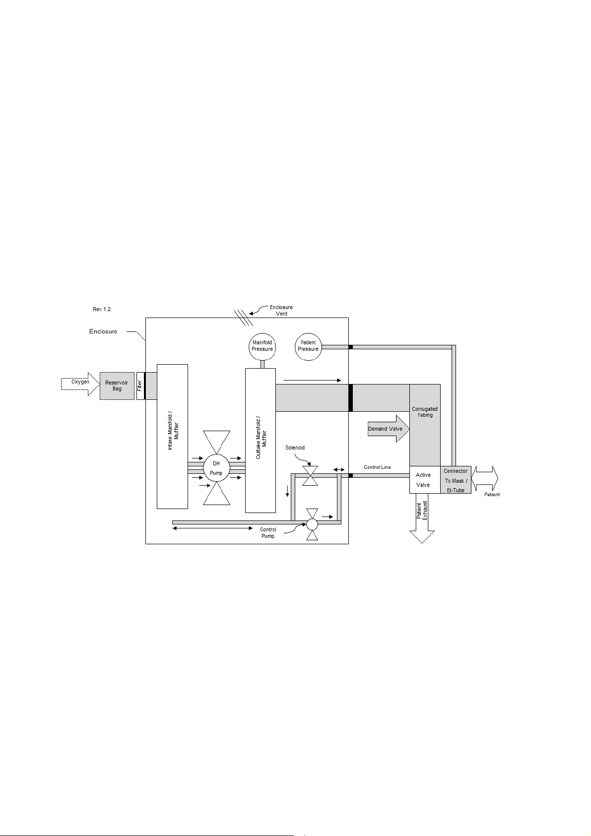
airway of choice and this setting will decrease the likelihood of gastric insufflation. While
the RR is
set to zero an alarm will sound if more than 30 seconds elapse since the last breath. To keep the
patient safe, in MASK CPR mode, the PEEP option is disabled so that the patient airway pressure
returns to 0 after the delivered breath. Also, to prevent false triggering due to compressions, the
Breath Assist feature is disabled.
In addition to delivering ambient air to the patient, the SAVe II also accepts supplemental oxygen
to increase the FIO2 to the patient. This is done through the use of a low-flow oxygen source (less
than 10 L/min) and a Reservoir Tube that connects between the oxygen source and the intake port
of the ventilator. During an exhalation phase, the reservoir tube will begin to fill with oxygen from
the oxygen source. During the inhalation phase, the SAVe II will draw from the reservoir tube, thus
pulling in oxygen to deliver to the patient. The amount of oxygen delivered to the patient is
dependent on the flow rate of the oxygen source, which is set by the user. A chart on page 30
guides the user to an appropriate oxygen flow rate depending on the TV, RR and FIO2 desired.
FIGURE 11: PNEUMATIC DIAGRAM
SAVe II OPERATION MANUAL Page 55
Page 56
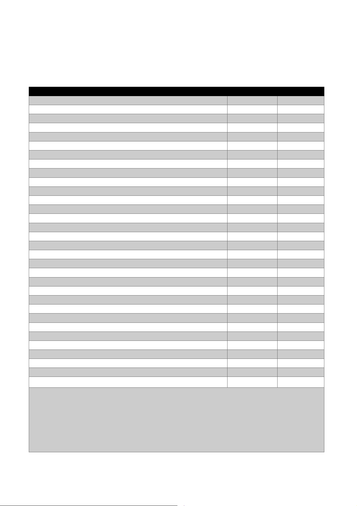
SAVe II Kits
1
:
SAVe II Kit with Hard Case, Metric, English, Type C Plug (Europe)
70100H
-EU 1
SAVe II Kit with Hard Case, Metric, Swedish, Type C Plug (Sweden)
70100H
-SE 1
2
Consumables:
Patient Ventilator Circuit, Disposable, Single
-
Use, SAVe II
, Case of 10
3
M40105
-
10 10
Mask and Inflation Syringe, Adult Medium
, Cas
e of 10
4, 5, 6
M40106
-
10 10
Head
-
harness
, Case of 10
6
E11001
-
10 10
Resupply Kit, Incl. 2ea Debris Filter and 1ea Intake Cover, SAVe II
, Package of 5
M41113
-5 5
Oxygen Reservoir, SAVe II
, Package of 5
3
M40092
-5 5
Noise Attenuator, SAVe II
, Package of 5
3
M41112
-5 5
Air Intake Debris Filter, Disposable, SAVe II
, Package of 50
F20053
-50 50
Battery Replacement Kit, SAVe II
7, 8
M40116
1
Accessories:
AC Power Supply / Battery Charger, SAVe II, Type A Plug
M40090
-A 1
AC Power Supply / Battery Charger, SA
Ve II, Type C Plug
M40090
-C 1
AC Power Supply / Battery Charger, SAVe II, Type G Plug
M40090
-G 1
Power Cord, Type A, (USA, Canada, Mexico, Japan) SAVe II
E11021
1
Power Cord, Type C, (Europe, Asia, South America, Iran) SAVe II
E11106
1
Power Cord, Type
G, (UK, Middle East, Malaysia, Singapore) SAVe II
E11105
1
Hard Case, SAVe II
F20055
1
Labelling:
Operation Manual, English, SAVe II
M40100
-EN 1
Operation Manual, Swedish, SAVe II
M40101
-SE 1
Operation Manual, Danish, SAVe II
M40101
-DK 1
Preventiv
e Maintenance Manual, English, SAVe II
M40101
-EN 1
1
The standard SAVe II kit includes 1ea SAVe II, 1ea SAVe II Patient Circuit, 1ea Hard Case, 1ea AC / Battery Charger, 1ea Oxyg
en
A
PPENDIX D - RE-ORDER INFORMATION
Item Part Number Per Package
SAVe II Kit with Hard Case, English, Type A Plug (USA) 70100H-US 1
SAVe II Kit with Hard Case, Metric, English, Type A Plug (Canada/Mexico) 70100H-CA 1
SAVe II Kit with Hard Case, Metric, Danish, Type C Plug (Denmark) 70100H-DK 1
SAVe II Kit with Hard Case, Metric, English, Type G Plug (UK/ME/Africa) 70100H-UK 1
SAVe II Kit with Hard Case, Metric, English, Type G Plug (Singapore) 70100H-SG 1
SAVe II Unit
SAVe II Unit2, Metric
M50012 N/A
M50013 N/A
Reservoir, 1ea Noise Attenuator, 1ea Patient Mask, 1ea Mask Inflation Syringe, 1ea Universal Head harness, 1ea Operator Manual
2
The SAVe II unit is only available for sale in a kit
3
Labeling in English unless specified otherwise
4
Mask labelling indicates alternative manufacturer part number 1055
5
The mask and syringe are only resupplied as a set
6
Item provided for convenience of user and may not be available in certain markets
7
Includes battery and required replacement hardware
8
Shipments of lithium-ion batteries without equipment: Domestic shipments by ground only. International air shipments limited to
quantity 4ea per shipment.
SAVe II OPERATION MANUAL Page 56
Page 57

R1.0.2
June 12, 2015
Initial release
Improve “Charge Level” reporting of Battery Cha
rger LED
mode.
A
PPENDIX E – SOFTWARE RELEASE HISTORY
Release
R1.0.3
R1.0.4
R1.0.5
Effective Date
November 9, 2015
Description of Change
Removed device alarm when battery temperature is below
0 (zero) degrees C
Displays software version on start-up
PIP & PEEP Display by hitting Confirm
June 10, 2016
Improve fault tolerance
Chirp when powering off
Improve recovery from low battery
Improves device ease of use by automatically releasing PEEP
July 20, 2016
(if enabled) when the device is switched into Manual Trigger
SAVe II OPERATION MANUAL Page 57
 Loading...