

Page 1
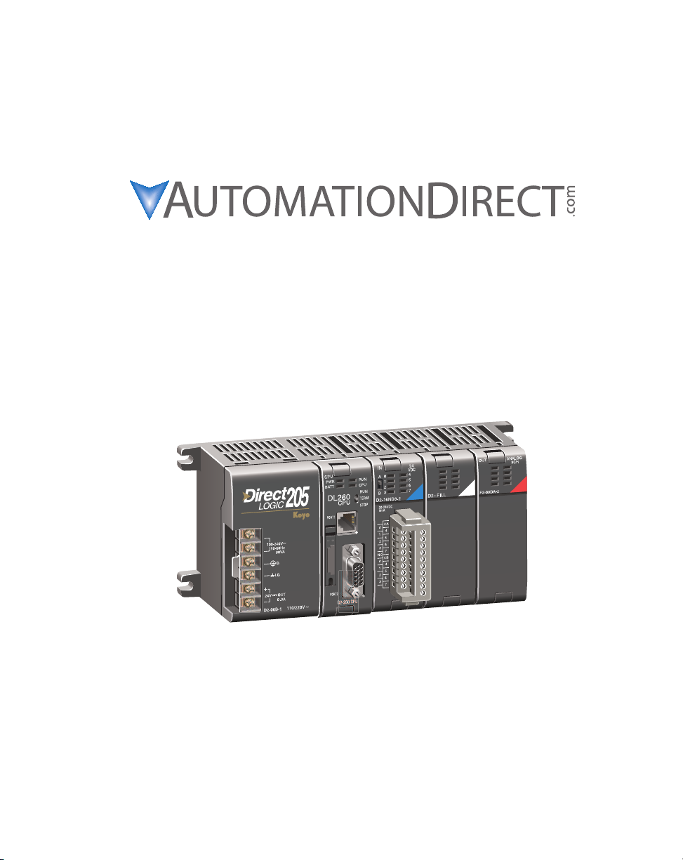
DL205 PLC User Manual
Volume 1 of 2
Manual Number: D2-USER-M
Page 2

WARNING
Thank you for purchasing automation equipment from Automationdirect.com®, doing business as,
AutomationDirect. We want your new automation equipment to operate safely. Anyone who installs or
uses this equipment should read this publication (and any other relevant publications) before installing or
operating the equipment.
To minimize the risk of potential safety problems, you should follow all applicable local and national codes
that regulate the installation and operation of your equipment. These codes vary from area to area and
usually change with time. It is your responsibility to determine which codes should be followed, and to
verify that the equipment, installation, and operation is in compliance with the latest revision of these
codes.
At a minimum, you should follow all applicable sections of the National Fire Code, National Electrical
Code, and the codes of the National Electrical Manufacturer's Association (NEMA). There may be local
regulatory or government offices that can also help determine which codes and standards are necessary for
safe installation and operation.
Equipment damage or serious injury to personnel can result from the failure to follow all applicable codes
and standards. We do not guarantee the products described in this publication are suitable for your
particular application, nor do we assume any responsibility for your product design, installation, or
operation.
Our products are not fault-tolerant and are not designed, manufactured or intended for use or resale as online control equipment in hazardous environments requiring fail-safe performance, such as in the
operation of nuclear facilities, aircraft navigation or communication systems, air traffic control, direct life
support machines, or weapons systems, in which the failure of the product could lead directly to death,
personal injury, or severe physical or environmental damage ("High Risk Activities"). AutomationDirect
specifically disclaims any expressed or implied warranty of fitness for High Risk Activities.
For additional warranty and safety information, see the Terms and Conditions section of our catalog. If
you have any questions concerning the installation or operation of this equipment, or if you need
additional information, please call us at 770-844-4200.
This publication is based on information that was available at the time it was printed. At
AutomationDirect we constantly strive to improve our products and services, so we reserve the right to
make changes to the products and/or publications at any time without notice and without any obligation.
This publication may also discuss features that may not be available in certain revisions of the product.
Trademarks
This publication may contain references to products produced and/or offered by other companies. The
product and company names may be trademarked and are the sole property of their respective owners.
AutomationDirect disclaims any proprietary interest in the marks and names of others.
Copyright 2012, Automationdirect.com Incorporated
No part of this manual shall be copied, reproduced, or transmitted in any way without the prior, written
consent of Automationdirect.com Incorporated. AutomationDirect retains the exclusive rights to all
information included in this document.
All Rights Reserved
Page 3

AVERTISSEMENT
Nous vous remercions d'avoir acheté l'équipement d'automatisation de Automationdirect.comMC, en faisant des
affaires comme, AutomationDirect. Nous tenons à ce que votre nouvel équipement d'automatisation fonctionne en
toute sécurité. Toute personne qui installe ou utilise cet équipement doit lire la présente publication (et toutes les
autres publications pertinentes) avant de l'installer ou de l'utiliser.
Afin de réduire au minimum le risque d'éventuels problèmes de sécurité, vous devez respecter tous les codes locaux et
nationaux applicables régissant l'installation et le fonctionnement de votre équipement. Ces codes diffèrent d'une
région à l'autre et, habituellement, évoluent au fil du temps. Il vous incombe de déterminer les codes à respecter et
de vous assurer que l'équipement, l'installation et le fonctionnement sont conformes aux exigences de la version la
plus récente de ces codes.
Vous devez, à tout le moins, respecter toutes les sections applicables du Code national de prévention des incendies,
du Code national de l'électricité et des codes de la National Electrical Manufacturer's Association (NEMA). Des
organismes de réglementation ou des services gouvernementaux locaux peuvent également vous aider à déterminer
les codes ainsi que les normes à respecter pour assurer une installation et un fonctionnement sûrs.
L'omission de respecter la totalité des codes et des normes applicables peut entraîner des dommages à l'équipement
ou causer de graves blessures au personnel. Nous ne garantissons pas que les produits décrits dans cette publication
conviennent à votre application particulière et nous n'assumons aucune responsabilité à l'égard de la conception, de
l'installation ou du fonctionnement de votre produit.
Nos produits ne sont pas insensibles aux défaillances et ne sont ni conçus ni fabriqués pour l'utilisation ou la revente
en tant qu'équipement de commande en ligne dans des environnements dangereux nécessitant une sécurité absolue,
par exemple, l'exploitation d'installations nucléaires, les systèmes de navigation aérienne ou de communication, le
contrôle de la circulation aérienne, les équipements de survie ou les systèmes d'armes, pour lesquels la défaillance du
produit peut provoquer la mort, des blessures corporelles ou de graves dommages matériels ou environnementaux
(«activités à risque élevé»). La société AutomationDirect nie toute garantie expresse ou implicite d'aptitude à
l'emploi en ce qui a trait aux activités à risque élevé.
Pour des renseignements additionnels touchant la garantie et la sécurité, veuillez consulter la section Modalités et
conditions de notre documentation. Si vous avez des questions au sujet de l'installation ou du fonctionnement de cet
équipement, ou encore si vous avez besoin de renseignements supplémentaires, n'hésitez pas à nous téléphoner au
770-844-4200.
Cette publication s'appuie sur l'information qui était disponible au moment de l'impression. À la société
AutomationDirect, nous nous efforçons constamment d'améliorer nos produits et services. C'est pourquoi nous
nous réservons le droit d'apporter des modifications aux produits ou aux publications en tout temps, sans préavis ni
quelque obligation que ce soit. La présente publication peut aussi porter sur des caractéristiques susceptibles de ne
pas être offertes dans certaines versions révisées du produit.
Marques de commerce
La présente publication peut contenir des références à des produits fabriqués ou offerts par d'autres entreprises. Les
désignations des produits et des entreprises peuvent être des marques de commerce et appartiennent exclusivement à
leurs propriétaires respectifs. AutomationDirect nie tout intérêt dans les autres marques et désignations.
Copyright 2012, Automationdirect.com Incorporated
Nulle partie de ce manuel ne doit être copiée, reproduite ou transmise de quelque façon que ce soit sans le
consentement préalable écrit de la société Automationdirect.com Incorporated. AutomationDirect conserve les
droits exclusifs à l'égard de tous les renseignements contenus dans le présent document.
Tous droits réservés
Page 4
DL205 PLC USER MANUAL
Please include the Manual Number and the Manual Issue, both shown below,
when communicating with Technical Support regarding this publication.
Manual Number: D2-USER-M
Issue: 4th Edition, Rev. B
Issue Date: 2/13
Publication History
Issue Date Description of Changes
1st Edition 1/94 original edition
Rev. A 9/95 minor corrections
2nd Edition 6/97 added DL250, downsized manual
Rev. A 5/98 minor corrections
Rev. B 7/99 added torque specs for base and I/O
Rev. C 11/99 minor corrections
Rev. D 3/00 added new PID features, minor corrections
Rev. E 11/00 added CE information, minor corrections
Rev. F 11/01
3rd Edition 6/02
Rev A 8/03 extensive corrections and additions
4th Edition 11/08
Rev A 4/10 extensive corrections and additions
Rev B 2/13
added surge protection info, corrected RLL and DRUM instructions,
minor corrections
added DL250–1 and DL260 CPUs, local expansion I/O, ASCII and
MODBUS instructions, split manual into two volumes
changed publishing software resulting in change of appearance, addition of IBox
instructions, changes to PID chapter, added info for ERM and EBC modules, other
changes as necessary
corrected number of memory registers needed in the print message instruction.
added new transient suppression for inductive loads to Chapter 2.
added H2-CTRIO2 and H2-ERM100 references.
Page 5

VOLUME ONE:
ABLE OF CONTENTS
T
Volume One: Table of Contents . . . . . . . . . . . . . . . . . . . . . . . . . . . . . . . .i
Volume Two: Table of Contents . . . . . . . . . . . . . . . . . . . . . . . . . . . . . . .xi
Chapter 1: Getting Started . . . . . . . . . . . . . . . . . . . . . . . . . . . . . . . . . .1
Introduction . . . . . . . . . . . . . . . . . . . . . . . . . . . . . . . . . . . . . . . . . . . . . . . . . . . . . . .1–2
The Purpose of this Manual . . . . . . . . . . . . . . . . . . . . . . . . . . . . . . . . . . . . . . . . . . .1–2
Where to Begin . . . . . . . . . . . . . . . . . . . . . . . . . . . . . . . . . . . . . . . . . . . . . . . . . . . .1–2
Supplemental Manuals . . . . . . . . . . . . . . . . . . . . . . . . . . . . . . . . . . . . . . . . . . . . . .1–2
Technical Support . . . . . . . . . . . . . . . . . . . . . . . . . . . . . . . . . . . . . . . . . . . . . . . . . .1–2
Conventions Used . . . . . . . . . . . . . . . . . . . . . . . . . . . . . . . . . . . . . . . . . . . . . . . . . . .1–3
Key Topics for Each Chapter . . . . . . . . . . . . . . . . . . . . . . . . . . . . . . . . . . . . . . . . . .1–3
DL205 System Components . . . . . . . . . . . . . . . . . . . . . . . . . . . . . . . . . . . . . . . . . . .1–4
CPUs . . . . . . . . . . . . . . . . . . . . . . . . . . . . . . . . . . . . . . . . . . . . . . . . . . . . . . . . . . . .1–4
Bases . . . . . . . . . . . . . . . . . . . . . . . . . . . . . . . . . . . . . . . . . . . . . . . . . . . . . . . . . . . .1–4
I/O Configuration . . . . . . . . . . . . . . . . . . . . . . . . . . . . . . . . . . . . . . . . . . . . . . . . . .1–4
I/O Modules . . . . . . . . . . . . . . . . . . . . . . . . . . . . . . . . . . . . . . . . . . . . . . . . . . . . . .1–4
DL205 System Diagrams . . . . . . . . . . . . . . . . . . . . . . . . . . . . . . . . . . . . . . . . . . . . .1–5
Programming Methods . . . . . . . . . . . . . . . . . . . . . . . . . . . . . . . . . . . . . . . . . . . . . . .1–7
DirectSOFT Programming for Windows. . . . . . . . . . . . . . . . . . . . . . . . . . . . . . . . . . .1–7
Handheld Programmer . . . . . . . . . . . . . . . . . . . . . . . . . . . . . . . . . . . . . . . . . . . . . .1–7
DirectLOGIC™ Part Numbering System . . . . . . . . . . . . . . . . . . . . . . . . . . . . . . . . . .1–8
Quick Start for PLC Validation and Programming . . . . . . . . . . . . . . . . . . . . . . . . .1–10
Steps to Designing a Successful System . . . . . . . . . . . . . . . . . . . . . . . . . . . . . . . .1–13
–1
Chapter 2: Installation, Wiring and Specifications . . . . . . . . . . . . . . .2–1
Safety Guidelines . . . . . . . . . . . . . . . . . . . . . . . . . . . . . . . . . . . . . . . . . . . . . . . . . . .2–2
Page 6

Table of Contents
Plan for Safety . . . . . . . . . . . . . . . . . . . . . . . . . . . . . . . . . . . . . . . . . . . . . . . . . . . . .2–2
Three Levels of Protection . . . . . . . . . . . . . . . . . . . . . . . . . . . . . . . . . . . . . . . . . . . .2–3
Emergency Stops . . . . . . . . . . . . . . . . . . . . . . . . . . . . . . . . . . . . . . . . . . . . . . . . . . .2–3
Emergency Power Disconnect . . . . . . . . . . . . . . . . . . . . . . . . . . . . . . . . . . . . . . . . .2–4
Orderly System Shutdown . . . . . . . . . . . . . . . . . . . . . . . . . . . . . . . . . . . . . . . . . . . .2–4
Class 1, Division 2, Approval . . . . . . . . . . . . . . . . . . . . . . . . . . . . . . . . . . . . . . . . . .2–4
Mounting Guidelines . . . . . . . . . . . . . . . . . . . . . . . . . . . . . . . . . . . . . . . . . . . . . . . .2–5
Base Dimensions . . . . . . . . . . . . . . . . . . . . . . . . . . . . . . . . . . . . . . . . . . . . . . . . . . .2–5
Panel Mounting and Layout . . . . . . . . . . . . . . . . . . . . . . . . . . . . . . . . . . . . . . . . . . .2–6
Enclosures . . . . . . . . . . . . . . . . . . . . . . . . . . . . . . . . . . . . . . . . . . . . . . . . . . . . . . . .2–7
Environmental Specifications . . . . . . . . . . . . . . . . . . . . . . . . . . . . . . . . . . . . . . . . . .2–8
Power . . . . . . . . . . . . . . . . . . . . . . . . . . . . . . . . . . . . . . . . . . . . . . . . . . . . . . . . . . .2–8
Marine Use . . . . . . . . . . . . . . . . . . . . . . . . . . . . . . . . . . . . . . . . . . . . . . . . . . . . . . .2–9
Agency Approvals . . . . . . . . . . . . . . . . . . . . . . . . . . . . . . . . . . . . . . . . . . . . . . . . . .2–9
24 VDC Power Bases . . . . . . . . . . . . . . . . . . . . . . . . . . . . . . . . . . . . . . . . . . . . . . .2–9
Installing DL205 Bases . . . . . . . . . . . . . . . . . . . . . . . . . . . . . . . . . . . . . . . . . . . . . .2–10
Choosing the Base Type . . . . . . . . . . . . . . . . . . . . . . . . . . . . . . . . . . . . . . . . . . . .2–10
Mounting the Base . . . . . . . . . . . . . . . . . . . . . . . . . . . . . . . . . . . . . . . . . . . . . . . .2–10
Using Mounting Rails . . . . . . . . . . . . . . . . . . . . . . . . . . . . . . . . . . . . . . . . . . . . . . .2–11
Installing Components in the Base . . . . . . . . . . . . . . . . . . . . . . . . . . . . . . . . . . . .2–12
Base Wiring Guidelines . . . . . . . . . . . . . . . . . . . . . . . . . . . . . . . . . . . . . . . . . . . . . .2–13
Base Wiring . . . . . . . . . . . . . . . . . . . . . . . . . . . . . . . . . . . . . . . . . . . . . . . . . . . . . .2–13
I/O Wiring Strategies . . . . . . . . . . . . . . . . . . . . . . . . . . . . . . . . . . . . . . . . . . . . . . .2–14
PLC Isolation Boundaries . . . . . . . . . . . . . . . . . . . . . . . . . . . . . . . . . . . . . . . . . . . .2–14
Powering I/O Circuits with the Auxiliary Supply . . . . . . . . . . . . . . . . . . . . . . . . . . .2–15
Powering I/O Circuits Using Separate Supplies . . . . . . . . . . . . . . . . . . . . . . . . . . .2–16
Sinking / Sourcing Concepts . . . . . . . . . . . . . . . . . . . . . . . . . . . . . . . . . . . . . . . . .2–17
I/O “Common” Terminal Concepts . . . . . . . . . . . . . . . . . . . . . . . . . . . . . . . . . . . .2–18
Connecting DC I/O to “Solid State” Field Devices . . . . . . . . . . . . . . . . . . . . . . . . .2–19
Solid State Input Sensors . . . . . . . . . . . . . . . . . . . . . . . . . . . . . . . . . . . . . . . . . . . .2–19
Solid State Output Loads . . . . . . . . . . . . . . . . . . . . . . . . . . . . . . . . . . . . . . . . . . . .2–19
Relay Output Guidelines . . . . . . . . . . . . . . . . . . . . . . . . . . . . . . . . . . . . . . . . . . . .2–21
Relay Outputs – Transient Suppression for Inductive Loads in a Control System . .2–21
I/O Modules Position, Wiring, and Specification . . . . . . . . . . . . . . . . . . . . . . . . . .2–26
Slot Numbering . . . . . . . . . . . . . . . . . . . . . . . . . . . . . . . . . . . . . . . . . . . . . . . . . . .2–26
Module Placement Restrictions . . . . . . . . . . . . . . . . . . . . . . . . . . . . . . . . . . . . . . .2–26
ii
DL205 User Manual, 4th Edition, Rev. B
Page 7

Table of Contents
Special Placement Considerations for Analog Modules . . . . . . . . . . . . . . . . . . . . .2–27
Discrete Input Module Status Indicators . . . . . . . . . . . . . . . . . . . . . . . . . . . . . . . .2–27
Color Coding of I/O Modules . . . . . . . . . . . . . . . . . . . . . . . . . . . . . . . . . . . . . . . .2–27
Wiring the Different Module Connectors . . . . . . . . . . . . . . . . . . . . . . . . . . . . . . . .2–28
I/O Wiring Checklist . . . . . . . . . . . . . . . . . . . . . . . . . . . . . . . . . . . . . . . . . . . . . . . .2–29
D2-08ND3, DC Input . . . . . . . . . . . . . . . . . . . . . . . . . . . . . . . . . . . . . . . . . . . . . . . .2–30
D2-16ND3-2, DC Input . . . . . . . . . . . . . . . . . . . . . . . . . . . . . . . . . . . . . . . . . . . . . .2–30
D2–32ND3, DC Input . . . . . . . . . . . . . . . . . . . . . . . . . . . . . . . . . . . . . . . . . . . . . . .2–31
D2–32ND3–2, DC Input . . . . . . . . . . . . . . . . . . . . . . . . . . . . . . . . . . . . . . . . . . . . .2–32
D2-08NA-1, AC Input . . . . . . . . . . . . . . . . . . . . . . . . . . . . . . . . . . . . . . . . . . . . . . .2–33
D2-08NA-2, AC Input . . . . . . . . . . . . . . . . . . . . . . . . . . . . . . . . . . . . . . . . . . . . . . .2–34
D2-16NA, AC Input . . . . . . . . . . . . . . . . . . . . . . . . . . . . . . . . . . . . . . . . . . . . . . . . .2–35
F2-08SIM, Input Simulator . . . . . . . . . . . . . . . . . . . . . . . . . . . . . . . . . . . . . . . . . . .2–35
D2-04TD1, DC Output . . . . . . . . . . . . . . . . . . . . . . . . . . . . . . . . . . . . . . . . . . . . . .2–36
D2–08TD1, DC Output . . . . . . . . . . . . . . . . . . . . . . . . . . . . . . . . . . . . . . . . . . . . . .2–37
D2–08TD2, DC Output . . . . . . . . . . . . . . . . . . . . . . . . . . . . . . . . . . . . . . . . . . . . . .2–37
D2–16TD1–2, DC Output . . . . . . . . . . . . . . . . . . . . . . . . . . . . . . . . . . . . . . . . . . . .2–38
D2–16TD2–2, DC Output . . . . . . . . . . . . . . . . . . . . . . . . . . . . . . . . . . . . . . . . . . . .2–38
F2–16TD1(2)P, DC Output With Fault Protection . . . . . . . . . . . . . . . . . . . . . . . . .2–39
F2–16TD1P, DC Output With Fault Protection . . . . . . . . . . . . . . . . . . . . . . . . . . .2–40
F2–16TD2P, DC Output with Fault Protection . . . . . . . . . . . . . . . . . . . . . . . . . . . .2–41
D2–32TD1, DC Output . . . . . . . . . . . . . . . . . . . . . . . . . . . . . . . . . . . . . . . . . . . . . .2–42
D2–32TD2, DC Output . . . . . . . . . . . . . . . . . . . . . . . . . . . . . . . . . . . . . . . . . . . . . .2–42
F2–08TA, AC Output . . . . . . . . . . . . . . . . . . . . . . . . . . . . . . . . . . . . . . . . . . . . . . . .2–43
D2–08TA, AC Output . . . . . . . . . . . . . . . . . . . . . . . . . . . . . . . . . . . . . . . . . . . . . . .2–43
D2–12TA, AC Output . . . . . . . . . . . . . . . . . . . . . . . . . . . . . . . . . . . . . . . . . . . . . . . .2–44
D2–04TRS, Relay Output . . . . . . . . . . . . . . . . . . . . . . . . . . . . . . . . . . . . . . . . . . . . .2–45
D2–08TR, Relay Output . . . . . . . . . . . . . . . . . . . . . . . . . . . . . . . . . . . . . . . . . . . . . .2–46
F2–08TR, Relay Output . . . . . . . . . . . . . . . . . . . . . . . . . . . . . . . . . . . . . . . . . . . . . .2–47
F2–08TRS, Relay Output . . . . . . . . . . . . . . . . . . . . . . . . . . . . . . . . . . . . . . . . . . . . .2–48
DL205 User Manual, 4th Edition, Rev. B
iii
Page 8

Table of Contents
D2–12TR, Relay Output . . . . . . . . . . . . . . . . . . . . . . . . . . . . . . . . . . . . . . . . . . . . . .2–49
D2–08CDR 4 pt., DC Input / 4pt., Relay Output . . . . . . . . . . . . . . . . . . . . . . . . . .2–50
Glossary of Specification Terms . . . . . . . . . . . . . . . . . . . . . . . . . . . . . . . . . . . . . . .2–51
Chapter 3: CPU Specifications and Operations . . . . . . . . . . . . . . . . . .3–1
CPU Overview . . . . . . . . . . . . . . . . . . . . . . . . . . . . . . . . . . . . . . . . . . . . . . . . . . . . . .3–2
General CPU Features . . . . . . . . . . . . . . . . . . . . . . . . . . . . . . . . . . . . . . . . . . . . . . .3–2
DL230 CPU Features . . . . . . . . . . . . . . . . . . . . . . . . . . . . . . . . . . . . . . . . . . . . . . . .3–2
DL240 CPU Features . . . . . . . . . . . . . . . . . . . . . . . . . . . . . . . . . . . . . . . . . . . . . . . .3–2
DL250–1 CPU Features . . . . . . . . . . . . . . . . . . . . . . . . . . . . . . . . . . . . . . . . . . . . . .3–3
DL260 CPU Features . . . . . . . . . . . . . . . . . . . . . . . . . . . . . . . . . . . . . . . . . . . . . . . .3–3
CPU General Specifications . . . . . . . . . . . . . . . . . . . . . . . . . . . . . . . . . . . . . . . . . . .3–4
CPU Base Electrical Specifications . . . . . . . . . . . . . . . . . . . . . . . . . . . . . . . . . . . . . .3–5
CPU Hardware Setup . . . . . . . . . . . . . . . . . . . . . . . . . . . . . . . . . . . . . . . . . . . . . . . .3–6
Communication Port Pinout Diagrams . . . . . . . . . . . . . . . . . . . . . . . . . . . . . . . . . . .3–6
Port 1 Specifications . . . . . . . . . . . . . . . . . . . . . . . . . . . . . . . . . . . . . . . . . . . . . . . .3–7
Port 2 Specifications . . . . . . . . . . . . . . . . . . . . . . . . . . . . . . . . . . . . . . . . . . . . . . . .3–8
Selecting the Program Storage Media . . . . . . . . . . . . . . . . . . . . . . . . . . . . . . . . . . .3–9
Built-in EEPROM . . . . . . . . . . . . . . . . . . . . . . . . . . . . . . . . . . . . . . . . . . . . . . . . . . .3–9
EEPROM Sizes . . . . . . . . . . . . . . . . . . . . . . . . . . . . . . . . . . . . . . . . . . . . . . . . . . . . .3–9
EEPROM Operations . . . . . . . . . . . . . . . . . . . . . . . . . . . . . . . . . . . . . . . . . . . . . . . .3–9
Installing the CPU . . . . . . . . . . . . . . . . . . . . . . . . . . . . . . . . . . . . . . . . . . . . . . . . .3–10
Connecting the Programming Devices . . . . . . . . . . . . . . . . . . . . . . . . . . . . . . . . .3–10
CPU Setup Information . . . . . . . . . . . . . . . . . . . . . . . . . . . . . . . . . . . . . . . . . . . . .3–11
Status Indicators . . . . . . . . . . . . . . . . . . . . . . . . . . . . . . . . . . . . . . . . . . . . . . . . . .3–12
Mode Switch Functions . . . . . . . . . . . . . . . . . . . . . . . . . . . . . . . . . . . . . . . . . . . . .3–12
Changing Modes in the DL205 PLC . . . . . . . . . . . . . . . . . . . . . . . . . . . . . . . . . . .3–13
Mode of Operation at Power-up . . . . . . . . . . . . . . . . . . . . . . . . . . . . . . . . . . . . . .3–13
Using Battery Backup . . . . . . . . . . . . . . . . . . . . . . . . . . . . . . . . . . . . . . . . . . . . . . .3–14
DL230 and DL240 . . . . . . . . . . . . . . . . . . . . . . . . . . . . . . . . . . . . . . . . . . . . . . . . .3–14
DL250-1 and DL260 . . . . . . . . . . . . . . . . . . . . . . . . . . . . . . . . . . . . . . . . . . . . . . .3–14
Battery Backup . . . . . . . . . . . . . . . . . . . . . . . . . . . . . . . . . . . . . . . . . . . . . . . . . . . .3–14
Auxiliary Functions . . . . . . . . . . . . . . . . . . . . . . . . . . . . . . . . . . . . . . . . . . . . . . . . .3–15
Clearing an Existing Program . . . . . . . . . . . . . . . . . . . . . . . . . . . . . . . . . . . . . . . . .3–16
Initializing System Memory . . . . . . . . . . . . . . . . . . . . . . . . . . . . . . . . . . . . . . . . . .3–16
iv
DL205 User Manual, 4th Edition, Rev. B
Page 9

Table of Contents
Setting the Clock and Calendar . . . . . . . . . . . . . . . . . . . . . . . . . . . . . . . . . . . . . . .3–16
Setting the CPU Network Address . . . . . . . . . . . . . . . . . . . . . . . . . . . . . . . . . . . . .3–17
Setting Retentive Memory Ranges . . . . . . . . . . . . . . . . . . . . . . . . . . . . . . . . . . . . .3–17
Using a Password . . . . . . . . . . . . . . . . . . . . . . . . . . . . . . . . . . . . . . . . . . . . . . . . . .3–18
Setting the Analog Potentiometer Ranges . . . . . . . . . . . . . . . . . . . . . . . . . . . . . . .3–19
CPU Operation . . . . . . . . . . . . . . . . . . . . . . . . . . . . . . . . . . . . . . . . . . . . . . . . . . . .3–21
CPU Operating System . . . . . . . . . . . . . . . . . . . . . . . . . . . . . . . . . . . . . . . . . . . . .3–21
Program Mode Operation . . . . . . . . . . . . . . . . . . . . . . . . . . . . . . . . . . . . . . . . . . .3–22
Run Mode Operation . . . . . . . . . . . . . . . . . . . . . . . . . . . . . . . . . . . . . . . . . . . . . . .3–22
Read Inputs . . . . . . . . . . . . . . . . . . . . . . . . . . . . . . . . . . . . . . . . . . . . . . . . . . . . . .3–23
Read Inputs from Specialty and Remote I/O . . . . . . . . . . . . . . . . . . . . . . . . . . . . .3–23
Service Peripherals and Force I/O . . . . . . . . . . . . . . . . . . . . . . . . . . . . . . . . . . . . . .3–23
CPU Bus Communication . . . . . . . . . . . . . . . . . . . . . . . . . . . . . . . . . . . . . . . . . . .3–24
Update Clock, Special Relays and Special Registers . . . . . . . . . . . . . . . . . . . . . . . .3–24
Solve Application Program . . . . . . . . . . . . . . . . . . . . . . . . . . . . . . . . . . . . . . . . . . .3–25
Solve PID Loop Equations . . . . . . . . . . . . . . . . . . . . . . . . . . . . . . . . . . . . . . . . . . .3–25
Write Outputs . . . . . . . . . . . . . . . . . . . . . . . . . . . . . . . . . . . . . . . . . . . . . . . . . . . .3–25
Write Outputs to Specialty and Remote I/O . . . . . . . . . . . . . . . . . . . . . . . . . . . . . .3–26
Diagnostics . . . . . . . . . . . . . . . . . . . . . . . . . . . . . . . . . . . . . . . . . . . . . . . . . . . . . .3–26
I/O Response Time . . . . . . . . . . . . . . . . . . . . . . . . . . . . . . . . . . . . . . . . . . . . . . . . .3–27
Is Timing Important for Your Application? . . . . . . . . . . . . . . . . . . . . . . . . . . . . . . .3–27
Normal Minimum I/O Response . . . . . . . . . . . . . . . . . . . . . . . . . . . . . . . . . . . . . .3–27
Normal Maximum I/O Response . . . . . . . . . . . . . . . . . . . . . . . . . . . . . . . . . . . . . .3–27
Improving Response Time . . . . . . . . . . . . . . . . . . . . . . . . . . . . . . . . . . . . . . . . . . .3–28
CPU Scan Time Considerations . . . . . . . . . . . . . . . . . . . . . . . . . . . . . . . . . . . . . . .3–29
Initialization Process . . . . . . . . . . . . . . . . . . . . . . . . . . . . . . . . . . . . . . . . . . . . . . . .3–30
Reading Inputs . . . . . . . . . . . . . . . . . . . . . . . . . . . . . . . . . . . . . . . . . . . . . . . . . . . .3–30
Reading Inputs from Specialty I/O . . . . . . . . . . . . . . . . . . . . . . . . . . . . . . . . . . . . .3–31
Service Peripherals . . . . . . . . . . . . . . . . . . . . . . . . . . . . . . . . . . . . . . . . . . . . . . . . .3–31
CPU Bus Communication . . . . . . . . . . . . . . . . . . . . . . . . . . . . . . . . . . . . . . . . . . .3–32
Update Clock/Calendar, Special Relays, Special Registers . . . . . . . . . . . . . . . . . . . .3–32
Writing Outputs . . . . . . . . . . . . . . . . . . . . . . . . . . . . . . . . . . . . . . . . . . . . . . . . . . .3–32
Writing Outputs to Specialty I/O . . . . . . . . . . . . . . . . . . . . . . . . . . . . . . . . . . . . . .3–33
Diagnostics . . . . . . . . . . . . . . . . . . . . . . . . . . . . . . . . . . . . . . . . . . . . . . . . . . . . . .3–33
Application Program Execution . . . . . . . . . . . . . . . . . . . . . . . . . . . . . . . . . . . . . . .3–34
PLC Numbering Systems . . . . . . . . . . . . . . . . . . . . . . . . . . . . . . . . . . . . . . . . . . . . .3–35
DL205 User Manual, 4th Edition, Rev. B
v
Page 10

Table of Contents
PLC Resources . . . . . . . . . . . . . . . . . . . . . . . . . . . . . . . . . . . . . . . . . . . . . . . . . . . .3–35
V–Memory . . . . . . . . . . . . . . . . . . . . . . . . . . . . . . . . . . . . . . . . . . . . . . . . . . . . . . .3–36
Binary-Coded Decimal Numbers . . . . . . . . . . . . . . . . . . . . . . . . . . . . . . . . . . . . . .3–36
Hexadecimal Numbers . . . . . . . . . . . . . . . . . . . . . . . . . . . . . . . . . . . . . . . . . . . . . .3–36
Memory Map . . . . . . . . . . . . . . . . . . . . . . . . . . . . . . . . . . . . . . . . . . . . . . . . . . . . . .3–37
Octal Numbering System . . . . . . . . . . . . . . . . . . . . . . . . . . . . . . . . . . . . . . . . . . .3–37
Discrete and Word Locations . . . . . . . . . . . . . . . . . . . . . . . . . . . . . . . . . . . . . . . . .3–37
V–Memory Locations for Discrete Memory Areas . . . . . . . . . . . . . . . . . . . . . . . . . .3–37
Input Points (X Data Type) . . . . . . . . . . . . . . . . . . . . . . . . . . . . . . . . . . . . . . . . . .3–38
Output Points (Y Data Type) . . . . . . . . . . . . . . . . . . . . . . . . . . . . . . . . . . . . . . . . .3–38
Control Relays (C Data Type) . . . . . . . . . . . . . . . . . . . . . . . . . . . . . . . . . . . . . . . . .3–38
Timers and Timer Status Bits (T Data type) . . . . . . . . . . . . . . . . . . . . . . . . . . . . . .3–38
Timer Current Values (V Data Type) . . . . . . . . . . . . . . . . . . . . . . . . . . . . . . . . . . . .3–39
Counters and Counter Status Bits (CT Data type) . . . . . . . . . . . . . . . . . . . . . . . . .3–39
Counter Current Values (V Data Type) . . . . . . . . . . . . . . . . . . . . . . . . . . . . . . . . . .3–39
Word Memory (V Data Type) . . . . . . . . . . . . . . . . . . . . . . . . . . . . . . . . . . . . . . . . .3–39
Stages (S Data type) . . . . . . . . . . . . . . . . . . . . . . . . . . . . . . . . . . . . . . . . . . . . . . .3–40
Special Relays (SP Data Type) . . . . . . . . . . . . . . . . . . . . . . . . . . . . . . . . . . . . . . . .3–40
Remote I/O Points (GX Data Type) . . . . . . . . . . . . . . . . . . . . . . . . . . . . . . . . . . . .3–40
DL230 System V-memory . . . . . . . . . . . . . . . . . . . . . . . . . . . . . . . . . . . . . . . . . . . .3–41
DL240 System V-memory . . . . . . . . . . . . . . . . . . . . . . . . . . . . . . . . . . . . . . . . . . . .3–43
DL250–1 System V-memory (DL250 also) . . . . . . . . . . . . . . . . . . . . . . . . . . . . . . .3–46
DL260 System V-memory . . . . . . . . . . . . . . . . . . . . . . . . . . . . . . . . . . . . . . . . . . . .3–49
DL205 Aliases . . . . . . . . . . . . . . . . . . . . . . . . . . . . . . . . . . . . . . . . . . . . . . . . . . . . .3–52
DL230 Memory Map . . . . . . . . . . . . . . . . . . . . . . . . . . . . . . . . . . . . . . . . . . . . . . . .3–53
DL240 Memory Map . . . . . . . . . . . . . . . . . . . . . . . . . . . . . . . . . . . . . . . . . . . . . . . .3–54
DL250–1 Memory Map (DL250 also) . . . . . . . . . . . . . . . . . . . . . . . . . . . . . . . . . . .3–55
DL260 Memory Map . . . . . . . . . . . . . . . . . . . . . . . . . . . . . . . . . . . . . . . . . . . . . . . .3–56
X Input/Y Output Bit Map . . . . . . . . . . . . . . . . . . . . . . . . . . . . . . . . . . . . . . . . . . .3–57
Control Relay Bit Map . . . . . . . . . . . . . . . . . . . . . . . . . . . . . . . . . . . . . . . . . . . . . . .3–59
Stage Control/Status Bit Map . . . . . . . . . . . . . . . . . . . . . . . . . . . . . . . . . . . . . . . .3–63
Timer and Counter Status Bit Maps . . . . . . . . . . . . . . . . . . . . . . . . . . . . . . . . . . . .3–65
Remote I/O Bit Map . . . . . . . . . . . . . . . . . . . . . . . . . . . . . . . . . . . . . . . . . . . . . . . .3–66
vi
DL205 User Manual, 4th Edition, Rev. B
Page 11

Table of Contents
Chapter 4: System Design and Configuration . . . . . . . . . . . . . . . . . . .4–1
DL205 System Design Strategies . . . . . . . . . . . . . . . . . . . . . . . . . . . . . . . . . . . . . . .4–2
I/O System Configurations . . . . . . . . . . . . . . . . . . . . . . . . . . . . . . . . . . . . . . . . . . . .4–2
Networking Configurations . . . . . . . . . . . . . . . . . . . . . . . . . . . . . . . . . . . . . . . . . . .4–2
Module Placement . . . . . . . . . . . . . . . . . . . . . . . . . . . . . . . . . . . . . . . . . . . . . . . . . .4–3
Slot Numbering . . . . . . . . . . . . . . . . . . . . . . . . . . . . . . . . . . . . . . . . . . . . . . . . . . . .4–3
Module Placement Restrictions . . . . . . . . . . . . . . . . . . . . . . . . . . . . . . . . . . . . . . . .4–3
Automatic I/O Configuration . . . . . . . . . . . . . . . . . . . . . . . . . . . . . . . . . . . . . . . . . .4–4
Manual I/O Configuration . . . . . . . . . . . . . . . . . . . . . . . . . . . . . . . . . . . . . . . . . . . .4–4
Removing a Manual Configuration . . . . . . . . . . . . . . . . . . . . . . . . . . . . . . . . . . . . .4–5
Power–On I/O Configuration Check . . . . . . . . . . . . . . . . . . . . . . . . . . . . . . . . . . . .4–5
I/O Points Required for Each Module . . . . . . . . . . . . . . . . . . . . . . . . . . . . . . . . . . . .4–6
Calculating the Power Budget . . . . . . . . . . . . . . . . . . . . . . . . . . . . . . . . . . . . . . . . .4–7
Managing your Power Resource . . . . . . . . . . . . . . . . . . . . . . . . . . . . . . . . . . . . . . .4–7
CPU Power Specifications . . . . . . . . . . . . . . . . . . . . . . . . . . . . . . . . . . . . . . . . . . . .4–7
Module Power Requirements . . . . . . . . . . . . . . . . . . . . . . . . . . . . . . . . . . . . . . . . . .4–7
Power Budget Calculation Example . . . . . . . . . . . . . . . . . . . . . . . . . . . . . . . . . . . . .4–9
Power Budget Calculation Worksheet . . . . . . . . . . . . . . . . . . . . . . . . . . . . . . . . . .4–10
Local Expansion I/O . . . . . . . . . . . . . . . . . . . . . . . . . . . . . . . . . . . . . . . . . . . . . . . .4–11
D2–CM Local Expansion Module . . . . . . . . . . . . . . . . . . . . . . . . . . . . . . . . . . . . . .4–11
D2–EM Local Expansion Module . . . . . . . . . . . . . . . . . . . . . . . . . . . . . . . . . . . . . .4–12
D2–EXCBL–1 Local Expansion Cable . . . . . . . . . . . . . . . . . . . . . . . . . . . . . . . . . . .4–12
DL260 Local Expansion System . . . . . . . . . . . . . . . . . . . . . . . . . . . . . . . . . . . . . . .4–13
DL250–1 Local Expansion System . . . . . . . . . . . . . . . . . . . . . . . . . . . . . . . . . . . . .4–14
Expansion Base Output Hold Option . . . . . . . . . . . . . . . . . . . . . . . . . . . . . . . . . . .4–15
Enabling I/O Configuration Check using DirectSOFT . . . . . . . . . . . . . . . . . . . . . . .4–16
Expanding DL205 I/O . . . . . . . . . . . . . . . . . . . . . . . . . . . . . . . . . . . . . . . . . . . . . . .4–17
I/O Expansion Overview . . . . . . . . . . . . . . . . . . . . . . . . . . . . . . . . . . . . . . . . . . . .4–17
Ethernet Remote Master, H2-ERM(100)(-F) . . . . . . . . . . . . . . . . . . . . . . . . . . . . . .4–17
Ethernet Remote Master Hardware Configuration . . . . . . . . . . . . . . . . . . . . . . . . .4–18
Installing the ERM Module . . . . . . . . . . . . . . . . . . . . . . . . . . . . . . . . . . . . . . . . . . .4–19
Ethernet Base Controller, H2-EBC(100)(-F) . . . . . . . . . . . . . . . . . . . . . . . . . . . . . . .4–22
Install the EBC Module . . . . . . . . . . . . . . . . . . . . . . . . . . . . . . . . . . . . . . . . . . . . .4–23
Set the Module ID . . . . . . . . . . . . . . . . . . . . . . . . . . . . . . . . . . . . . . . . . . . . . . . . .4–23
Insert the EBC Module . . . . . . . . . . . . . . . . . . . . . . . . . . . . . . . . . . . . . . . . . . . . . .4–23
Network Cabling . . . . . . . . . . . . . . . . . . . . . . . . . . . . . . . . . . . . . . . . . . . . . . . . . .4–24
DL205 User Manual, 4th Edition, Rev. B
vii
Page 12

Table of Contents
10BaseFL Network Cabling . . . . . . . . . . . . . . . . . . . . . . . . . . . . . . . . . . . . . . . . . .4–25
Maximum Cable Length . . . . . . . . . . . . . . . . . . . . . . . . . . . . . . . . . . . . . . . . . . . .4–25
Add a Serial Remote I/O Master/Slave Module . . . . . . . . . . . . . . . . . . . . . . . . . . .4–26
Configuring the CPU’s Remote I/O Channel . . . . . . . . . . . . . . . . . . . . . . . . . . . . .4–27
Configure Remote I/O Slaves . . . . . . . . . . . . . . . . . . . . . . . . . . . . . . . . . . . . . . . . .4–29
Configuring the Remote I/O Table . . . . . . . . . . . . . . . . . . . . . . . . . . . . . . . . . . . . .4–29
Remote I/O Setup Program . . . . . . . . . . . . . . . . . . . . . . . . . . . . . . . . . . . . . . . . . .4–30
Remote I/O Test Program . . . . . . . . . . . . . . . . . . . . . . . . . . . . . . . . . . . . . . . . . . .4–31
Network Connections to Modbus and DirectNet . . . . . . . . . . . . . . . . . . . . . . . . . .4–32
Configuring Port 2 For DirectNet . . . . . . . . . . . . . . . . . . . . . . . . . . . . . . . . . . . . . .4–32
Configuring Port 2 For Modbus RTU . . . . . . . . . . . . . . . . . . . . . . . . . . . . . . . . . . .4–32
Modbus Port Configuration . . . . . . . . . . . . . . . . . . . . . . . . . . . . . . . . . . . . . . . . . .4–33
DirectNET Port Configuration . . . . . . . . . . . . . . . . . . . . . . . . . . . . . . . . . . . . . . . .4–34
Network Slave Operation . . . . . . . . . . . . . . . . . . . . . . . . . . . . . . . . . . . . . . . . . . . .4–35
Modbus Function Codes Supported . . . . . . . . . . . . . . . . . . . . . . . . . . . . . . . . . . .4–35
Determining the Modbus Address . . . . . . . . . . . . . . . . . . . . . . . . . . . . . . . . . . . . .4–35
If Your Host Software Requires the Data Type and Address . . . . . . . . . . . . . . . . . .4–35
If Your Modbus Host Software Requires an Address ONLY . . . . . . . . . . . . . . . . . . .4–38
Example 1: V2100 584/984 Mode . . . . . . . . . . . . . . . . . . . . . . . . . . . . . . . . . . . . .4–40
Example 2: Y20 584/984 Mode . . . . . . . . . . . . . . . . . . . . . . . . . . . . . . . . . . . . . . .4–40
Example 3: T10 Current Value 484 Mode . . . . . . . . . . . . . . . . . . . . . . . . . . . . . . .4–40
Example 4: C54 584/984 Mode . . . . . . . . . . . . . . . . . . . . . . . . . . . . . . . . . . . . . .4–40
Determining the DirectNET Address . . . . . . . . . . . . . . . . . . . . . . . . . . . . . . . . . . . .4–40
Network Master Operation . . . . . . . . . . . . . . . . . . . . . . . . . . . . . . . . . . . . . . . . . .4–41
Communications from a Ladder Program . . . . . . . . . . . . . . . . . . . . . . . . . . . . . . .4–44
Multiple Read and Write Interlocks . . . . . . . . . . . . . . . . . . . . . . . . . . . . . . . . . . . .4–44
Network Modbus RTU Master Operation (DL260 only) . . . . . . . . . . . . . . . . . . . .4–45
Modbus Function Codes Supported . . . . . . . . . . . . . . . . . . . . . . . . . . . . . . . . . . .4–45
Modbus Port Configuration . . . . . . . . . . . . . . . . . . . . . . . . . . . . . . . . . . . . . . . . . .4–46
RS–485 Network (Modbus only) . . . . . . . . . . . . . . . . . . . . . . . . . . . . . . . . . . . . . .4–47
RS–232 Network . . . . . . . . . . . . . . . . . . . . . . . . . . . . . . . . . . . . . . . . . . . . . . . . . .4–47
Modbus Read from Network (MRX) . . . . . . . . . . . . . . . . . . . . . . . . . . . . . . . . . . . .4–48
MRX Slave Memory Address . . . . . . . . . . . . . . . . . . . . . . . . . . . . . . . . . . . . . . . . .4–49
MRX Master Memory Addresses . . . . . . . . . . . . . . . . . . . . . . . . . . . . . . . . . . . . . .4–49
MRX Number of Elements . . . . . . . . . . . . . . . . . . . . . . . . . . . . . . . . . . . . . . . . . . .4–49
MRX Exception Response Buffer . . . . . . . . . . . . . . . . . . . . . . . . . . . . . . . . . . . . . .4–49
Modbus Write to Network (MWX) . . . . . . . . . . . . . . . . . . . . . . . . . . . . . . . . . . . . .4–50
viii
DL205 User Manual, 4th Edition, Rev. B
Page 13

Table of Contents
MWX Slave Memory Address . . . . . . . . . . . . . . . . . . . . . . . . . . . . . . . . . . . . . . . . .4–51
MWX Master Memory Addresses . . . . . . . . . . . . . . . . . . . . . . . . . . . . . . . . . . . . . .4–51
MWX Number of Elements . . . . . . . . . . . . . . . . . . . . . . . . . . . . . . . . . . . . . . . . . .4–51
MWX Exception Response Buffer . . . . . . . . . . . . . . . . . . . . . . . . . . . . . . . . . . . . . .4–51
MRX/MWX Example in DirectSOFT . . . . . . . . . . . . . . . . . . . . . . . . . . . . . . . . . . . .4–52
Multiple Read and Write Interlocks . . . . . . . . . . . . . . . . . . . . . . . . . . . . . . . . . . . .4–52
Non–Sequence Protocol (ASCII In/Out and PRINT) . . . . . . . . . . . . . . . . . . . . . . .4–54
Configure the DL260 Port 2 for Non-Sequence . . . . . . . . . . . . . . . . . . . . . . . . . . .4–54
RS–485 Network . . . . . . . . . . . . . . . . . . . . . . . . . . . . . . . . . . . . . . . . . . . . . . . . . .4–55
RS–232 Network . . . . . . . . . . . . . . . . . . . . . . . . . . . . . . . . . . . . . . . . . . . . . . . . . .4–55
Configure the DL250-1 Port 2 for Non-Sequence . . . . . . . . . . . . . . . . . . . . . . . . .4–56
RS–422 Network . . . . . . . . . . . . . . . . . . . . . . . . . . . . . . . . . . . . . . . . . . . . . . . . . .4–57
RS–232 Network . . . . . . . . . . . . . . . . . . . . . . . . . . . . . . . . . . . . . . . . . . . . . . . . . .4–57
Chapter 5: RLL and Intelligent Box (IBOX) Instructions . . . . . . . . . . .5–1
Introduction . . . . . . . . . . . . . . . . . . . . . . . . . . . . . . . . . . . . . . . . . . . . . . . . . . . . . . .5–2
Using Boolean Instructions . . . . . . . . . . . . . . . . . . . . . . . . . . . . . . . . . . . . . . . . . . . .5–5
END Statement . . . . . . . . . . . . . . . . . . . . . . . . . . . . . . . . . . . . . . . . . . . . . . . . . . . .5–5
Simple Rungs . . . . . . . . . . . . . . . . . . . . . . . . . . . . . . . . . . . . . . . . . . . . . . . . . . . . . .5–5
Normally Closed Contact . . . . . . . . . . . . . . . . . . . . . . . . . . . . . . . . . . . . . . . . . . . . .5–6
Contacts in Series . . . . . . . . . . . . . . . . . . . . . . . . . . . . . . . . . . . . . . . . . . . . . . . . . .5–6
Midline Outputs . . . . . . . . . . . . . . . . . . . . . . . . . . . . . . . . . . . . . . . . . . . . . . . . . . .5–6
Parallel Elements . . . . . . . . . . . . . . . . . . . . . . . . . . . . . . . . . . . . . . . . . . . . . . . . . . .5–7
Joining Series Branches in Parallel . . . . . . . . . . . . . . . . . . . . . . . . . . . . . . . . . . . . . .5–7
Joining Parallel Branches in Series . . . . . . . . . . . . . . . . . . . . . . . . . . . . . . . . . . . . . .5–7
Combination Networks . . . . . . . . . . . . . . . . . . . . . . . . . . . . . . . . . . . . . . . . . . . . . .5–7
Comparative Boolean . . . . . . . . . . . . . . . . . . . . . . . . . . . . . . . . . . . . . . . . . . . . . . .5–8
Boolean Stack . . . . . . . . . . . . . . . . . . . . . . . . . . . . . . . . . . . . . . . . . . . . . . . . . . . . .5–8
Immediate Boolean . . . . . . . . . . . . . . . . . . . . . . . . . . . . . . . . . . . . . . . . . . . . . . . . .5–9
Boolean Instructions . . . . . . . . . . . . . . . . . . . . . . . . . . . . . . . . . . . . . . . . . . . . . . .5–10
Comparative Boolean . . . . . . . . . . . . . . . . . . . . . . . . . . . . . . . . . . . . . . . . . . . . . . .5–27
Immediate Instructions . . . . . . . . . . . . . . . . . . . . . . . . . . . . . . . . . . . . . . . . . . . . . .5–33
Timer, Counter and Shift Register Instructions . . . . . . . . . . . . . . . . . . . . . . . . . . .5–41
Using Timers . . . . . . . . . . . . . . . . . . . . . . . . . . . . . . . . . . . . . . . . . . . . . . . . . . . . .5–41
Timer Example Using Discrete Status Bits . . . . . . . . . . . . . . . . . . . . . . . . . . . . . . . .5–43
DL205 User Manual, 4th Edition, Rev. B
ix
Page 14

Table of Contents
Timer Example Using Comparative Contacts . . . . . . . . . . . . . . . . . . . . . . . . . . . . .5–43
Accumulating Timer (TMRA) . . . . . . . . . . . . . . . . . . . . . . . . . . . . . . . . . . . . . . . . .5–44
Accumulating Timer Example using Discrete Status Bits . . . . . . . . . . . . . . . . . . . . .5–45
Accumulator Timer Example Using Comparative Contacts . . . . . . . . . . . . . . . . . . .5–45
Counter Example Using Discrete Status Bits . . . . . . . . . . . . . . . . . . . . . . . . . . . . . .5–47
Counter Example Using Comparative Contacts . . . . . . . . . . . . . . . . . . . . . . . . . . .5–47
Stage Counter Example Using Discrete Status Bits . . . . . . . . . . . . . . . . . . . . . . . . .5–49
Stage Counter Example Using Comparative Contacts . . . . . . . . . . . . . . . . . . . . . .5–49
Up/Down Counter Example Using Discrete Status Bits . . . . . . . . . . . . . . . . . . . . .5–51
Up/Down Counter Example Using Comparative Contacts . . . . . . . . . . . . . . . . . . .5–51
Accumulator/Stack Load and Output Data Instructions . . . . . . . . . . . . . . . . . . . .5–53
Logical Instructions (Accumulator) . . . . . . . . . . . . . . . . . . . . . . . . . . . . . . . . . . . .5–71
Math Instructions . . . . . . . . . . . . . . . . . . . . . . . . . . . . . . . . . . . . . . . . . . . . . . . . . .5–88
Transcendental Functions (DL260 only) . . . . . . . . . . . . . . . . . . . . . . . . . . . . . . . .5–121
Bit Operation Instructions . . . . . . . . . . . . . . . . . . . . . . . . . . . . . . . . . . . . . . . . . .5–123
Number Conversion Instructions (Accumulator) . . . . . . . . . . . . . . . . . . . . . . . . .5–130
Table Instructions . . . . . . . . . . . . . . . . . . . . . . . . . . . . . . . . . . . . . . . . . . . . . . . . .5–144
Clock/Calendar Instructions . . . . . . . . . . . . . . . . . . . . . . . . . . . . . . . . . . . . . . . . .5–175
CPU Control Instructions . . . . . . . . . . . . . . . . . . . . . . . . . . . . . . . . . . . . . . . . . . .5–177
Program Control Instructions . . . . . . . . . . . . . . . . . . . . . . . . . . . . . . . . . . . . . . . .5–179
Interrupt Instructions . . . . . . . . . . . . . . . . . . . . . . . . . . . . . . . . . . . . . . . . . . . . . .5–187
Intelligent I/O Instructions . . . . . . . . . . . . . . . . . . . . . . . . . . . . . . . . . . . . . . . . . .5–191
Network Instructions . . . . . . . . . . . . . . . . . . . . . . . . . . . . . . . . . . . . . . . . . . . . . .5–193
Message Instructions . . . . . . . . . . . . . . . . . . . . . . . . . . . . . . . . . . . . . . . . . . . . . .5–197
Modbus RTU Instructions (DL260) . . . . . . . . . . . . . . . . . . . . . . . . . . . . . . . . . . . .5–205
Modbus Read from Network (MRX) . . . . . . . . . . . . . . . . . . . . . . . . . . . . . . . . . . .5–205
Modbus Write to Network (MWX) . . . . . . . . . . . . . . . . . . . . . . . . . . . . . . . . . . . .5–208
ASCII Instructions (DL260) . . . . . . . . . . . . . . . . . . . . . . . . . . . . . . . . . . . . . . . . . .5–211
Intelligent Box (IBox) Instructions (DL250-1/DL260) . . . . . . . . . . . . . . . . . . . . .5-230
x
DL205 User Manual, 4th Edition, Rev. B
Page 15

Table of Contents
VOLUME TWO:
ABLE OF CONTENTS
T
Chapter 6: Drum Instruction Programming (DL250-1/DL260 only) .6–1
Introduction . . . . . . . . . . . . . . . . . . . . . . . . . . . . . . . . . . . . . . . . . . . . . . . . . . . . . . .6–2
Purpose . . . . . . . . . . . . . . . . . . . . . . . . . . . . . . . . . . . . . . . . . . . . . . . . . . . . . . . . . .6–2
Drum Terminology . . . . . . . . . . . . . . . . . . . . . . . . . . . . . . . . . . . . . . . . . . . . . . . . .6–2
Drum Chart Representation . . . . . . . . . . . . . . . . . . . . . . . . . . . . . . . . . . . . . . . . . . .6–3
Output Sequences . . . . . . . . . . . . . . . . . . . . . . . . . . . . . . . . . . . . . . . . . . . . . . . . . .6–3
Step Transitions . . . . . . . . . . . . . . . . . . . . . . . . . . . . . . . . . . . . . . . . . . . . . . . . . . . . .6–4
Drum Instruction Types . . . . . . . . . . . . . . . . . . . . . . . . . . . . . . . . . . . . . . . . . . . . . .6–4
Timer-Only Transitions . . . . . . . . . . . . . . . . . . . . . . . . . . . . . . . . . . . . . . . . . . . . . . .6–4
Timer and Event Transitions . . . . . . . . . . . . . . . . . . . . . . . . . . . . . . . . . . . . . . . . . . .6–5
Event-Only Transitions . . . . . . . . . . . . . . . . . . . . . . . . . . . . . . . . . . . . . . . . . . . . . . .6–6
Counter Assignments . . . . . . . . . . . . . . . . . . . . . . . . . . . . . . . . . . . . . . . . . . . . . . . .6–6
Last Step Completion . . . . . . . . . . . . . . . . . . . . . . . . . . . . . . . . . . . . . . . . . . . . . . .6–7
Overview of Drum Operation . . . . . . . . . . . . . . . . . . . . . . . . . . . . . . . . . . . . . . . . . .6–8
Drum Instruction Block Diagram . . . . . . . . . . . . . . . . . . . . . . . . . . . . . . . . . . . . . . .6–8
Powerup State of Drum Registers . . . . . . . . . . . . . . . . . . . . . . . . . . . . . . . . . . . . . .6–9
Drum Control Techniques . . . . . . . . . . . . . . . . . . . . . . . . . . . . . . . . . . . . . . . . . . . .6–10
Drum Control Inputs . . . . . . . . . . . . . . . . . . . . . . . . . . . . . . . . . . . . . . . . . . . . . . .6–10
Self-Resetting Drum . . . . . . . . . . . . . . . . . . . . . . . . . . . . . . . . . . . . . . . . . . . . . . . .6–11
Initializing Drum Outputs . . . . . . . . . . . . . . . . . . . . . . . . . . . . . . . . . . . . . . . . . . .6–11
Using Complex Event Step Transitions . . . . . . . . . . . . . . . . . . . . . . . . . . . . . . . . . .6–11
Drum Instruction . . . . . . . . . . . . . . . . . . . . . . . . . . . . . . . . . . . . . . . . . . . . . . . . . . .6–12
Timed Drum with Discrete Outputs (DRUM) . . . . . . . . . . . . . . . . . . . . . . . . . . . . .6–12
Event Drum (EDRUM) . . . . . . . . . . . . . . . . . . . . . . . . . . . . . . . . . . . . . . . . . . . . . .6–14
Handheld Programmer Drum Mnemonics . . . . . . . . . . . . . . . . . . . . . . . . . . . . . . .6–16
DL205 User Manual, 4th Edition, Rev. B
xi
Page 16

Table of Contents
Masked Event Drum with Discrete Outputs (MDRMD) . . . . . . . . . . . . . . . . . . . . .6–19
Masked Event Drum with Word Output (MDRMW) . . . . . . . . . . . . . . . . . . . . . . . .6–21
Chapter 7: RLL
Introduction to Stage Programming . . . . . . . . . . . . . . . . . . . . . . . . . . . . . . . . . . . .7–2
Overcoming “Stage Fright” . . . . . . . . . . . . . . . . . . . . . . . . . . . . . . . . . . . . . . . . . . .7–2
Learning to Draw State Transition Diagrams . . . . . . . . . . . . . . . . . . . . . . . . . . . . .7–3
Introduction to Process States . . . . . . . . . . . . . . . . . . . . . . . . . . . . . . . . . . . . . . . . .7–3
The Need for State Diagrams . . . . . . . . . . . . . . . . . . . . . . . . . . . . . . . . . . . . . . . . . .7–3
A 2–State Process . . . . . . . . . . . . . . . . . . . . . . . . . . . . . . . . . . . . . . . . . . . . . . . . . . .7–3
RLL Equivalent . . . . . . . . . . . . . . . . . . . . . . . . . . . . . . . . . . . . . . . . . . . . . . . . . . . . .7–4
Stage Equivalent . . . . . . . . . . . . . . . . . . . . . . . . . . . . . . . . . . . . . . . . . . . . . . . . . . .7–4
Let’s Compare . . . . . . . . . . . . . . . . . . . . . . . . . . . . . . . . . . . . . . . . . . . . . . . . . . . . .7–5
Initial Stages . . . . . . . . . . . . . . . . . . . . . . . . . . . . . . . . . . . . . . . . . . . . . . . . . . . . . .7–5
What Stage Bits Do . . . . . . . . . . . . . . . . . . . . . . . . . . . . . . . . . . . . . . . . . . . . . . . . .7–6
Stage Instruction Characteristics . . . . . . . . . . . . . . . . . . . . . . . . . . . . . . . . . . . . . . .7–6
Using the Stage Jump Instruction for State Transitions . . . . . . . . . . . . . . . . . . . . .7–7
Stage Jump, Set, and Reset Instructions . . . . . . . . . . . . . . . . . . . . . . . . . . . . . . . . . .7–7
Stage Program Example: Toggle On/Off Lamp Controller . . . . . . . . . . . . . . . . . . .7–8
A 4–State Process . . . . . . . . . . . . . . . . . . . . . . . . . . . . . . . . . . . . . . . . . . . . . . . . . . .7–8
Four Steps to Writing a Stage Program . . . . . . . . . . . . . . . . . . . . . . . . . . . . . . . . . .7–9
Stage Program Example: A Garage Door Opener . . . . . . . . . . . . . . . . . . . . . . . . .7–10
Garage Door Opener Example . . . . . . . . . . . . . . . . . . . . . . . . . . . . . . . . . . . . . . . .7–10
Draw the Block Diagram . . . . . . . . . . . . . . . . . . . . . . . . . . . . . . . . . . . . . . . . . . . .7–10
Draw the State Diagram . . . . . . . . . . . . . . . . . . . . . . . . . . . . . . . . . . . . . . . . . . . .7–11
Add Safety Light Feature . . . . . . . . . . . . . . . . . . . . . . . . . . . . . . . . . . . . . . . . . . . .7–12
Modify the Block Diagram and State Diagram . . . . . . . . . . . . . . . . . . . . . . . . . . . .7–12
Using a Timer Inside a Stage . . . . . . . . . . . . . . . . . . . . . . . . . . . . . . . . . . . . . . . . .7–13
Add Emergency Stop Feature . . . . . . . . . . . . . . . . . . . . . . . . . . . . . . . . . . . . . . . . .7–14
Exclusive Transitions . . . . . . . . . . . . . . . . . . . . . . . . . . . . . . . . . . . . . . . . . . . . . . . .7–14
PLUS
Stage Programming . . . . . . . . . . . . . . . . . . . . . . . .7–1
Stage Program Design Considerations . . . . . . . . . . . . . . . . . . . . . . . . . . . . . . . . .7–15
Stage Program Organization . . . . . . . . . . . . . . . . . . . . . . . . . . . . . . . . . . . . . . . . .7–15
How Instructions Work Inside Stages . . . . . . . . . . . . . . . . . . . . . . . . . . . . . . . . . . .7–16
Using a Stage as a Supervisory Process . . . . . . . . . . . . . . . . . . . . . . . . . . . . . . . . .7–17
Stage Counter . . . . . . . . . . . . . . . . . . . . . . . . . . . . . . . . . . . . . . . . . . . . . . . . . . . .7–17
xii
DL205 User Manual, 4th Edition, Rev. B
Page 17

Table of Contents
Unconditional Outputs . . . . . . . . . . . . . . . . . . . . . . . . . . . . . . . . . . . . . . . . . . . . .7–18
Power Flow Transition Technique . . . . . . . . . . . . . . . . . . . . . . . . . . . . . . . . . . . . . .7–18
Parallel Processing Concepts . . . . . . . . . . . . . . . . . . . . . . . . . . . . . . . . . . . . . . . . .7–19
Parallel Processes . . . . . . . . . . . . . . . . . . . . . . . . . . . . . . . . . . . . . . . . . . . . . . . . . .7–19
Converging Processes . . . . . . . . . . . . . . . . . . . . . . . . . . . . . . . . . . . . . . . . . . . . . .7–19
Convergence Stages (CV) . . . . . . . . . . . . . . . . . . . . . . . . . . . . . . . . . . . . . . . . . . .7–19
Convergence Jump (CVJMP) . . . . . . . . . . . . . . . . . . . . . . . . . . . . . . . . . . . . . . . . .7–20
Convergence Stage Guidelines . . . . . . . . . . . . . . . . . . . . . . . . . . . . . . . . . . . . . . .7–20
Managing Large Programs . . . . . . . . . . . . . . . . . . . . . . . . . . . . . . . . . . . . . . . . . . .7–21
Stage Blocks (BLK, BEND) . . . . . . . . . . . . . . . . . . . . . . . . . . . . . . . . . . . . . . . . . . .7–21
Block Call (BCALL) . . . . . . . . . . . . . . . . . . . . . . . . . . . . . . . . . . . . . . . . . . . . . . . . .7–22
PLUS
RLL
(Stage) Instructions . . . . . . . . . . . . . . . . . . . . . . . . . . . . . . . . . . . . . . . . . .7–23
Stage (SG) . . . . . . . . . . . . . . . . . . . . . . . . . . . . . . . . . . . . . . . . . . . . . . . . . . . . . . .7–23
Initial Stage (ISG) . . . . . . . . . . . . . . . . . . . . . . . . . . . . . . . . . . . . . . . . . . . . . . . . . .7–24
Jump (JMP) . . . . . . . . . . . . . . . . . . . . . . . . . . . . . . . . . . . . . . . . . . . . . . . . . . . . . .7–24
Not Jump (NJMP) . . . . . . . . . . . . . . . . . . . . . . . . . . . . . . . . . . . . . . . . . . . . . . . . .7–24
Converge Stage (CV) and Converge Jump (CVJMP) . . . . . . . . . . . . . . . . . . . . . . . .7–25
Block Call (BCALL) . . . . . . . . . . . . . . . . . . . . . . . . . . . . . . . . . . . . . . . . . . . . . . . . .7–27
Block (BLK) . . . . . . . . . . . . . . . . . . . . . . . . . . . . . . . . . . . . . . . . . . . . . . . . . . . . . .7–27
Block End (BEND) . . . . . . . . . . . . . . . . . . . . . . . . . . . . . . . . . . . . . . . . . . . . . . . . .7–27
Stage View in DirectSOFT . . . . . . . . . . . . . . . . . . . . . . . . . . . . . . . . . . . . . . . . . . .7–28
Questions and Answers about Stage Programming . . . . . . . . . . . . . . . . . . . . . . .7–29
Chapter 8: PID Loop Operation . . . . . . . . . . . . . . . . . . . . . . . . . . . . . .8–1
DL250-1 and DL260 PID Loop Features . . . . . . . . . . . . . . . . . . . . . . . . . . . . . . . . . .8–2
Main Features . . . . . . . . . . . . . . . . . . . . . . . . . . . . . . . . . . . . . . . . . . . . . . . . . . . . .8–2
Introduction to PID Control . . . . . . . . . . . . . . . . . . . . . . . . . . . . . . . . . . . . . . . . . . .8–4
Why use PID Control? . . . . . . . . . . . . . . . . . . . . . . . . . . . . . . . . . . . . . . . . . . . . . . .8–4
Introducing DL205 PID Control . . . . . . . . . . . . . . . . . . . . . . . . . . . . . . . . . . . . . . . .8–6
Process Control Definitions . . . . . . . . . . . . . . . . . . . . . . . . . . . . . . . . . . . . . . . . . . .8–8
PID Loop Operation . . . . . . . . . . . . . . . . . . . . . . . . . . . . . . . . . . . . . . . . . . . . . . . . .8–9
Position Form of the PID Equation . . . . . . . . . . . . . . . . . . . . . . . . . . . . . . . . . . . . . .8–9
Reset Windup Protection . . . . . . . . . . . . . . . . . . . . . . . . . . . . . . . . . . . . . . . . . . . .8–10
Freeze Bias . . . . . . . . . . . . . . . . . . . . . . . . . . . . . . . . . . . . . . . . . . . . . . . . . . . . . . .8–11
Adjusting the Bias . . . . . . . . . . . . . . . . . . . . . . . . . . . . . . . . . . . . . . . . . . . . . . . . .8–11
DL205 User Manual, 4th Edition, Rev. B
xiii
Page 18

Table of Contents
Step Bias Proportional to Step Change in SP . . . . . . . . . . . . . . . . . . . . . . . . . . . . .8–12
Eliminating Proportional, Integral or Derivative Action . . . . . . . . . . . . . . . . . . . . . .8–12
Velocity Form of the PID Equation . . . . . . . . . . . . . . . . . . . . . . . . . . . . . . . . . . . . .8–12
Bumpless Transfer . . . . . . . . . . . . . . . . . . . . . . . . . . . . . . . . . . . . . . . . . . . . . . . . .8–13
Loop Alarms . . . . . . . . . . . . . . . . . . . . . . . . . . . . . . . . . . . . . . . . . . . . . . . . . . . . .8–13
Loop Operating Modes . . . . . . . . . . . . . . . . . . . . . . . . . . . . . . . . . . . . . . . . . . . . .8–14
Special Loop Calculations . . . . . . . . . . . . . . . . . . . . . . . . . . . . . . . . . . . . . . . . . . .8–14
Ten Steps to Successful Process Control . . . . . . . . . . . . . . . . . . . . . . . . . . . . . . . .8–16
PID Loop Setup . . . . . . . . . . . . . . . . . . . . . . . . . . . . . . . . . . . . . . . . . . . . . . . . . . . .8–18
Some Things to Do and Know Before Starting . . . . . . . . . . . . . . . . . . . . . . . . . . . .8–18
PID Error Flags . . . . . . . . . . . . . . . . . . . . . . . . . . . . . . . . . . . . . . . . . . . . . . . . . . . .8–18
Establishing the Loop Table Size and Location . . . . . . . . . . . . . . . . . . . . . . . . . . . .8–18
Loop Table Word Definitions . . . . . . . . . . . . . . . . . . . . . . . . . . . . . . . . . . . . . . . . .8–20
PID Mode Setting 1 Bit Descriptions (Addr + 00) . . . . . . . . . . . . . . . . . . . . . . . . . .8–21
PID Mode Setting 2 Bit Descriptions (Addr + 01) . . . . . . . . . . . . . . . . . . . . . . . . . .8–22
Mode/Alarm Monitoring Word (Addr + 06) . . . . . . . . . . . . . . . . . . . . . . . . . . . . . .8–23
Ramp/Soak Table Flags (Addr + 33) . . . . . . . . . . . . . . . . . . . . . . . . . . . . . . . . . . . .8–23
Ramp/Soak Table Location (Addr + 34) . . . . . . . . . . . . . . . . . . . . . . . . . . . . . . . . .8–24
Ramp/Soak Table Programming Error Flags (Addr + 35) . . . . . . . . . . . . . . . . . . . .8–24
PV Auto Transfer (Addr + 36) from I/O Module Base/Slot/Channel Option . . . . . .8–25
PV Auto Transfer (Addr + 36) from V-memory Option . . . . . . . . . . . . . . . . . . . . . .8–25
Control Output Auto Transfer (Addr + 37) . . . . . . . . . . . . . . . . . . . . . . . . . . . . . . .8–25
Configure the PID Loop . . . . . . . . . . . . . . . . . . . . . . . . . . . . . . . . . . . . . . . . . . . . .8–26
PID Loop Tuning . . . . . . . . . . . . . . . . . . . . . . . . . . . . . . . . . . . . . . . . . . . . . . . . . . .8–41
Open-Loop Test . . . . . . . . . . . . . . . . . . . . . . . . . . . . . . . . . . . . . . . . . . . . . . . . . . .8–41
Manual Tuning Procedure . . . . . . . . . . . . . . . . . . . . . . . . . . . . . . . . . . . . . . . . . . .8–42
Alternative Manual Tuning Procedures by Others . . . . . . . . . . . . . . . . . . . . . . . . .8–44
Tuning PID Controllers . . . . . . . . . . . . . . . . . . . . . . . . . . . . . . . . . . . . . . . . . . . . . .8–44
Auto Tuning Procedure . . . . . . . . . . . . . . . . . . . . . . . . . . . . . . . . . . . . . . . . . . . . .8–45
Use DirectSOFT Data View with PID View . . . . . . . . . . . . . . . . . . . . . . . . . . . . . . .8–49
Open a New Data View Window . . . . . . . . . . . . . . . . . . . . . . . . . . . . . . . . . . . . . .8–49
Open PID View . . . . . . . . . . . . . . . . . . . . . . . . . . . . . . . . . . . . . . . . . . . . . . . . . . .8–50
Using the Special PID Features . . . . . . . . . . . . . . . . . . . . . . . . . . . . . . . . . . . . . . . .8–52
How to Change Loop Modes . . . . . . . . . . . . . . . . . . . . . . . . . . . . . . . . . . . . . . . . .8–52
Operator Panel Control of PID Modes . . . . . . . . . . . . . . . . . . . . . . . . . . . . . . . . . .8–53
PLC Modes Effect on Loop Modes . . . . . . . . . . . . . . . . . . . . . . . . . . . . . . . . . . . . .8–53
xiv
DL205 User Manual, 4th Edition, Rev. B
Page 19

Table of Contents
Loop Mode Override . . . . . . . . . . . . . . . . . . . . . . . . . . . . . . . . . . . . . . . . . . . . . . .8–53
PV Analog Filter . . . . . . . . . . . . . . . . . . . . . . . . . . . . . . . . . . . . . . . . . . . . . . . . . . .8–54
Creating an Analog Filter in Ladder Logic . . . . . . . . . . . . . . . . . . . . . . . . . . . . . . .8–55
Use the DirectSOFT 5 Filter Intelligent Box (IBOX) Instruction . . . . . . . . . . . . . . .8–56
FilterB Example . . . . . . . . . . . . . . . . . . . . . . . . . . . . . . . . . . . . . . . . . . . . . . . . . . .8–56
Ramp/Soak Generator . . . . . . . . . . . . . . . . . . . . . . . . . . . . . . . . . . . . . . . . . . . . . .8–57
Introduction . . . . . . . . . . . . . . . . . . . . . . . . . . . . . . . . . . . . . . . . . . . . . . . . . . . . .8–57
Ramp/Soak Table . . . . . . . . . . . . . . . . . . . . . . . . . . . . . . . . . . . . . . . . . . . . . . . . . .8–58
Ramp/Soak Table Flags . . . . . . . . . . . . . . . . . . . . . . . . . . . . . . . . . . . . . . . . . . . . .8–60
Ramp/Soak Generator Enable . . . . . . . . . . . . . . . . . . . . . . . . . . . . . . . . . . . . . . . .8–60
Ramp/Soak Controls . . . . . . . . . . . . . . . . . . . . . . . . . . . . . . . . . . . . . . . . . . . . . . .8–60
Ramp/Soak Profile Monitoring . . . . . . . . . . . . . . . . . . . . . . . . . . . . . . . . . . . . . . . .8–61
Ramp/Soak Programming Errors . . . . . . . . . . . . . . . . . . . . . . . . . . . . . . . . . . . . . .8–61
Testing Your Ramp/Soak Profile . . . . . . . . . . . . . . . . . . . . . . . . . . . . . . . . . . . . . . .8–61
DirectSOFT Ramp/Soak Example . . . . . . . . . . . . . . . . . . . . . . . . . . . . . . . . . . . . . . .8–62
Setup the Profile in PID Setup . . . . . . . . . . . . . . . . . . . . . . . . . . . . . . . . . . . . . . . .8–62
Program the Ramp/Soak Control in Relay Ladder . . . . . . . . . . . . . . . . . . . . . . . . .8–62
Test the Profile . . . . . . . . . . . . . . . . . . . . . . . . . . . . . . . . . . . . . . . . . . . . . . . . . . . .8–63
Cascade Control . . . . . . . . . . . . . . . . . . . . . . . . . . . . . . . . . . . . . . . . . . . . . . . . . . .8–64
Introduction . . . . . . . . . . . . . . . . . . . . . . . . . . . . . . . . . . . . . . . . . . . . . . . . . . . . .8–64
Cascaded Loops in the DL205 CPU . . . . . . . . . . . . . . . . . . . . . . . . . . . . . . . . . . . .8–65
Tuning Cascaded Loops . . . . . . . . . . . . . . . . . . . . . . . . . . . . . . . . . . . . . . . . . . . . .8–66
Time-Proportioning Control . . . . . . . . . . . . . . . . . . . . . . . . . . . . . . . . . . . . . . . . . .8–67
On/Off Control Program Example . . . . . . . . . . . . . . . . . . . . . . . . . . . . . . . . . . . . .8–68
Feedforward Control . . . . . . . . . . . . . . . . . . . . . . . . . . . . . . . . . . . . . . . . . . . . . . .8–69
Feedforward Example . . . . . . . . . . . . . . . . . . . . . . . . . . . . . . . . . . . . . . . . . . . . . .8–70
PID Example Program . . . . . . . . . . . . . . . . . . . . . . . . . . . . . . . . . . . . . . . . . . . . . . .8–71
Program Setup for the PID Loop . . . . . . . . . . . . . . . . . . . . . . . . . . . . . . . . . . . . . .8–71
Troubleshooting Tips . . . . . . . . . . . . . . . . . . . . . . . . . . . . . . . . . . . . . . . . . . . . . . .8–74
Glossary of PID Loop Terminology . . . . . . . . . . . . . . . . . . . . . . . . . . . . . . . . . . . . .8–76
Bibliography . . . . . . . . . . . . . . . . . . . . . . . . . . . . . . . . . . . . . . . . . . . . . . . . . . . . . .8–78
Chapter 9: Maintenance and Troubleshooting . . . . . . . . . . . . . . . . . .9–1
Hardware Maintenance . . . . . . . . . . . . . . . . . . . . . . . . . . . . . . . . . . . . . . . . . . . . . .9–2
DL205 User Manual, 4th Edition, Rev. B
xv
Page 20

Table of Contents
Standard Maintenance . . . . . . . . . . . . . . . . . . . . . . . . . . . . . . . . . . . . . . . . . . . . . . .9–2
Air Quality Maintenance . . . . . . . . . . . . . . . . . . . . . . . . . . . . . . . . . . . . . . . . . . . . .9–2
Low Battery Indicator . . . . . . . . . . . . . . . . . . . . . . . . . . . . . . . . . . . . . . . . . . . . . . .9–2
CPU Battery Replacement . . . . . . . . . . . . . . . . . . . . . . . . . . . . . . . . . . . . . . . . . . . .9–2
Diagnostics . . . . . . . . . . . . . . . . . . . . . . . . . . . . . . . . . . . . . . . . . . . . . . . . . . . . . . . .9–3
Diagnostics . . . . . . . . . . . . . . . . . . . . . . . . . . . . . . . . . . . . . . . . . . . . . . . . . . . . . . .9–3
Fatal Errors . . . . . . . . . . . . . . . . . . . . . . . . . . . . . . . . . . . . . . . . . . . . . . . . . . . . . . . .9–3
Non-fatal Errors . . . . . . . . . . . . . . . . . . . . . . . . . . . . . . . . . . . . . . . . . . . . . . . . . . . .9–3
Finding Diagnostic Information . . . . . . . . . . . . . . . . . . . . . . . . . . . . . . . . . . . . . . . .9–4
V-memory Locations Corresponding to Error Codes . . . . . . . . . . . . . . . . . . . . . . . .9–4
Special Relays (SP) Corresponding to Error Codes . . . . . . . . . . . . . . . . . . . . . . . . . .9–5
I/O Module Codes . . . . . . . . . . . . . . . . . . . . . . . . . . . . . . . . . . . . . . . . . . . . . . . . . .9–6
Error Message Tables . . . . . . . . . . . . . . . . . . . . . . . . . . . . . . . . . . . . . . . . . . . . . . . .9–7
System Error Codes . . . . . . . . . . . . . . . . . . . . . . . . . . . . . . . . . . . . . . . . . . . . . . . . .9–8
Program Error Codes . . . . . . . . . . . . . . . . . . . . . . . . . . . . . . . . . . . . . . . . . . . . . . . .9–9
CPU Error Indicators . . . . . . . . . . . . . . . . . . . . . . . . . . . . . . . . . . . . . . . . . . . . . . . .9–10
PWR Indicator . . . . . . . . . . . . . . . . . . . . . . . . . . . . . . . . . . . . . . . . . . . . . . . . . . . .9–11
Incorrect Base Power . . . . . . . . . . . . . . . . . . . . . . . . . . . . . . . . . . . . . . . . . . . . . . .9–11
Faulty CPU . . . . . . . . . . . . . . . . . . . . . . . . . . . . . . . . . . . . . . . . . . . . . . . . . . . . . . .9–11
Device or Module causing the Power Supply to Shutdown . . . . . . . . . . . . . . . . . .9–12
Power Budget Exceeded . . . . . . . . . . . . . . . . . . . . . . . . . . . . . . . . . . . . . . . . . . . .9–12
Run Indicator . . . . . . . . . . . . . . . . . . . . . . . . . . . . . . . . . . . . . . . . . . . . . . . . . . . . .9–13
CPU Indicator . . . . . . . . . . . . . . . . . . . . . . . . . . . . . . . . . . . . . . . . . . . . . . . . . . . .9–13
BATT Indicator . . . . . . . . . . . . . . . . . . . . . . . . . . . . . . . . . . . . . . . . . . . . . . . . . . . .9–13
Communications Problems . . . . . . . . . . . . . . . . . . . . . . . . . . . . . . . . . . . . . . . . . . .9–13
I/O Module Troubleshooting . . . . . . . . . . . . . . . . . . . . . . . . . . . . . . . . . . . . . . . . .9–14
Things to Check . . . . . . . . . . . . . . . . . . . . . . . . . . . . . . . . . . . . . . . . . . . . . . . . . .9–14
I/O Diagnostics . . . . . . . . . . . . . . . . . . . . . . . . . . . . . . . . . . . . . . . . . . . . . . . . . . .9–14
Some Quick Steps . . . . . . . . . . . . . . . . . . . . . . . . . . . . . . . . . . . . . . . . . . . . . . . . .9–15
Testing Output Points . . . . . . . . . . . . . . . . . . . . . . . . . . . . . . . . . . . . . . . . . . . . . .9–16
Handheld Programmer Keystrokes Used to Test an Output Point . . . . . . . . . . . . . .9–16
Noise Troubleshooting . . . . . . . . . . . . . . . . . . . . . . . . . . . . . . . . . . . . . . . . . . . . . .9–17
Electrical Noise Problems . . . . . . . . . . . . . . . . . . . . . . . . . . . . . . . . . . . . . . . . . . . .9–17
Reducing Electrical Noise . . . . . . . . . . . . . . . . . . . . . . . . . . . . . . . . . . . . . . . . . . . .9–17
Machine Startup and Program Troubleshooting . . . . . . . . . . . . . . . . . . . . . . . . . .9–18
xvi
DL205 User Manual, 4th Edition, Rev. B
Page 21

Table of Contents
Syntax Check . . . . . . . . . . . . . . . . . . . . . . . . . . . . . . . . . . . . . . . . . . . . . . . . . . . . .9–18
Duplicate Reference Check . . . . . . . . . . . . . . . . . . . . . . . . . . . . . . . . . . . . . . . . . .9–19
TEST-PGM and TEST-RUN Modes . . . . . . . . . . . . . . . . . . . . . . . . . . . . . . . . . . . . . .9–20
Special Instructions . . . . . . . . . . . . . . . . . . . . . . . . . . . . . . . . . . . . . . . . . . . . . . . .9–22
Run Time Edits . . . . . . . . . . . . . . . . . . . . . . . . . . . . . . . . . . . . . . . . . . . . . . . . . . . .9–24
Forcing I/O Points . . . . . . . . . . . . . . . . . . . . . . . . . . . . . . . . . . . . . . . . . . . . . . . . .9–26
Regular Forcing with Direct Access . . . . . . . . . . . . . . . . . . . . . . . . . . . . . . . . . . . .9–28
Bit Override Forcing . . . . . . . . . . . . . . . . . . . . . . . . . . . . . . . . . . . . . . . . . . . . . . . .9–29
Bit Override Indicators . . . . . . . . . . . . . . . . . . . . . . . . . . . . . . . . . . . . . . . . . . . . . .9–29
Appendix A: Auxiliary Functions . . . . . . . . . . . . . . . . . . . . . . . . . . . . .A–1
Introduction . . . . . . . . . . . . . . . . . . . . . . . . . . . . . . . . . . . . . . . . . . . . . . . . . . . . . . .A–2
What are Auxiliary Functions? . . . . . . . . . . . . . . . . . . . . . . . . . . . . . . . . . . . . . . . . .A–2
Accessing AUX Functions via DirectSOFT . . . . . . . . . . . . . . . . . . . . . . . . . . . . . . . . .A–3
Accessing AUX Functions via the Handheld Programmer . . . . . . . . . . . . . . . . . . . . .A–3
AUX 2* — RLL Operations . . . . . . . . . . . . . . . . . . . . . . . . . . . . . . . . . . . . . . . . . . . .A–4
AUX 21-24 . . . . . . . . . . . . . . . . . . . . . . . . . . . . . . . . . . . . . . . . . . . . . . . . . . . . . . .A–4
AUX 21 Check Program . . . . . . . . . . . . . . . . . . . . . . . . . . . . . . . . . . . . . . . . . . . . . .A–4
AUX 22 Change Reference . . . . . . . . . . . . . . . . . . . . . . . . . . . . . . . . . . . . . . . . . . .A–4
AUX 23 Clear Ladder Range . . . . . . . . . . . . . . . . . . . . . . . . . . . . . . . . . . . . . . . . . .A–4
AUX 24 Clear Ladders . . . . . . . . . . . . . . . . . . . . . . . . . . . . . . . . . . . . . . . . . . . . . . .A–4
AUX 3* — V-memory Operations . . . . . . . . . . . . . . . . . . . . . . . . . . . . . . . . . . . . . . .A–5
AUX 31 . . . . . . . . . . . . . . . . . . . . . . . . . . . . . . . . . . . . . . . . . . . . . . . . . . . . . . . . . .A–5
AUX 31 Clear V-Memory . . . . . . . . . . . . . . . . . . . . . . . . . . . . . . . . . . . . . . . . . . . . .A–5
AUX 4* — I/O Configuration . . . . . . . . . . . . . . . . . . . . . . . . . . . . . . . . . . . . . . . . . .A–5
AUX 41-46 . . . . . . . . . . . . . . . . . . . . . . . . . . . . . . . . . . . . . . . . . . . . . . . . . . . . . . .A–5
AUX 41 Show I/O Configuration . . . . . . . . . . . . . . . . . . . . . . . . . . . . . . . . . . . . . . .A–5
AUX 42 I/O Diagnostics . . . . . . . . . . . . . . . . . . . . . . . . . . . . . . . . . . . . . . . . . . . . . .A–5
AUX 44 Power-up Configuration Check . . . . . . . . . . . . . . . . . . . . . . . . . . . . . . . . . .A–5
AUX 45 Select Configuration . . . . . . . . . . . . . . . . . . . . . . . . . . . . . . . . . . . . . . . . . .A–6
AUX 46 to I/O Configuration . . . . . . . . . . . . . . . . . . . . . . . . . . . . . . . . . . . . . . . . . .A–6
AUX 5* — CPU Configuration . . . . . . . . . . . . . . . . . . . . . . . . . . . . . . . . . . . . . . . . .A–7
AUX 51-5C . . . . . . . . . . . . . . . . . . . . . . . . . . . . . . . . . . . . . . . . . . . . . . . . . . . . . . .A–7
AUX 51 Modify Program Name . . . . . . . . . . . . . . . . . . . . . . . . . . . . . . . . . . . . . . . .A–7
AUX 52 Display/Change Calendar . . . . . . . . . . . . . . . . . . . . . . . . . . . . . . . . . . . . . .A–7
AUX 53 Display Scan Time . . . . . . . . . . . . . . . . . . . . . . . . . . . . . . . . . . . . . . . . . . .A–8
DL205 User Manual, 4th Edition, Rev. B
xvii
Page 22

Table of Contents
AUX 54 Initialize Scratchpad . . . . . . . . . . . . . . . . . . . . . . . . . . . . . . . . . . . . . . . . . .A–8
AUX 55 Set Watchdog Timer . . . . . . . . . . . . . . . . . . . . . . . . . . . . . . . . . . . . . . . . . .A–8
AUX 56 CPU Network Address . . . . . . . . . . . . . . . . . . . . . . . . . . . . . . . . . . . . . . . .A–8
AUX 57 Set Retentive Ranges . . . . . . . . . . . . . . . . . . . . . . . . . . . . . . . . . . . . . . . . .A–9
AUX 58 Test Operations . . . . . . . . . . . . . . . . . . . . . . . . . . . . . . . . . . . . . . . . . . . . .A–9
AUX 59 Bit Override . . . . . . . . . . . . . . . . . . . . . . . . . . . . . . . . . . . . . . . . . . . . . . .A–10
AUX 5B Counter Interface Configuration . . . . . . . . . . . . . . . . . . . . . . . . . . . . . . . .A–10
AUX 5C Display Error History . . . . . . . . . . . . . . . . . . . . . . . . . . . . . . . . . . . . . . . . .A–11
AUX 6* — Handheld Programmer Configuration . . . . . . . . . . . . . . . . . . . . . . . . .A–12
AUX 61, 62 and 65 . . . . . . . . . . . . . . . . . . . . . . . . . . . . . . . . . . . . . . . . . . . . . . . .A–12
AUX 61 Show Revision Numbers . . . . . . . . . . . . . . . . . . . . . . . . . . . . . . . . . . . . . .A–12
AUX 62 Beeper On/Off . . . . . . . . . . . . . . . . . . . . . . . . . . . . . . . . . . . . . . . . . . . . .A–12
AUX 65 Run Self Diagnostics . . . . . . . . . . . . . . . . . . . . . . . . . . . . . . . . . . . . . . . . .A–12
AUX 7* - EEPROM Operations . . . . . . . . . . . . . . . . . . . . . . . . . . . . . . . . . . . . . . . .A–12
AUX 71 - 76 . . . . . . . . . . . . . . . . . . . . . . . . . . . . . . . . . . . . . . . . . . . . . . . . . . . . .A–12
Transferrable Memory Areas . . . . . . . . . . . . . . . . . . . . . . . . . . . . . . . . . . . . . . . . .A–13
AUX 71 CPU to HPP EEPROM . . . . . . . . . . . . . . . . . . . . . . . . . . . . . . . . . . . . . . . .A–13
AUX 72 HPP EEPROM to CPU . . . . . . . . . . . . . . . . . . . . . . . . . . . . . . . . . . . . . . . .A–13
AUX 73 Compare HPP EEPROM to CPU . . . . . . . . . . . . . . . . . . . . . . . . . . . . . . . . .A–13
AUX 74 HPP EEPROM Blank Check . . . . . . . . . . . . . . . . . . . . . . . . . . . . . . . . . . . .A–13
AUX 75 Erase HPP EEPROM . . . . . . . . . . . . . . . . . . . . . . . . . . . . . . . . . . . . . . . . . .A–13
AUX 76 Show EEPROM Type . . . . . . . . . . . . . . . . . . . . . . . . . . . . . . . . . . . . . . . . .A–13
AUX 8* — Password Operations . . . . . . . . . . . . . . . . . . . . . . . . . . . . . . . . . . . . . .A–14
AUX 81 - 83 . . . . . . . . . . . . . . . . . . . . . . . . . . . . . . . . . . . . . . . . . . . . . . . . . . . . .A–14
AUX 81 Modify Password . . . . . . . . . . . . . . . . . . . . . . . . . . . . . . . . . . . . . . . . . . .A–14
AUX 82 Unlock CPU . . . . . . . . . . . . . . . . . . . . . . . . . . . . . . . . . . . . . . . . . . . . . . .A–14
AUX 83 Lock CPU . . . . . . . . . . . . . . . . . . . . . . . . . . . . . . . . . . . . . . . . . . . . . . . . .A–14
Appendix B: DL205 Error Codes . . . . . . . . . . . . . . . . . . . . . . . . . . . . .B–1
Appendix C: Instruction Execution Times . . . . . . . . . . . . . . . . . . . . . .C–1
Introduction . . . . . . . . . . . . . . . . . . . . . . . . . . . . . . . . . . . . . . . . . . . . . . . . . . . . . . .C–2
V-Memory Data Registers . . . . . . . . . . . . . . . . . . . . . . . . . . . . . . . . . . . . . . . . . . . .C–2
V-Memory Bit Registers . . . . . . . . . . . . . . . . . . . . . . . . . . . . . . . . . . . . . . . . . . . . . .C–2
How to Read the Tables . . . . . . . . . . . . . . . . . . . . . . . . . . . . . . . . . . . . . . . . . . . . . .C–2
Boolean Instructions . . . . . . . . . . . . . . . . . . . . . . . . . . . . . . . . . . . . . . . . . . . . . . . . .C–3
xviii
DL205 User Manual, 4th Edition, Rev. B
Page 23

Table of Contents
Comparative Boolean Instructions . . . . . . . . . . . . . . . . . . . . . . . . . . . . . . . . . . . . . .C–4
Bit of Word Boolean Instructions . . . . . . . . . . . . . . . . . . . . . . . . . . . . . . . . . . . . . .C–13
Immediate Instructions . . . . . . . . . . . . . . . . . . . . . . . . . . . . . . . . . . . . . . . . . . . . . .C–14
Timer, Counter and Shift Register Instructions . . . . . . . . . . . . . . . . . . . . . . . . . . .C–15
Accumulator Data Instructions . . . . . . . . . . . . . . . . . . . . . . . . . . . . . . . . . . . . . . . .C–16
Logical Instructions . . . . . . . . . . . . . . . . . . . . . . . . . . . . . . . . . . . . . . . . . . . . . . . . .C–18
Math Instructions . . . . . . . . . . . . . . . . . . . . . . . . . . . . . . . . . . . . . . . . . . . . . . . . . .C–20
Differential Instructions . . . . . . . . . . . . . . . . . . . . . . . . . . . . . . . . . . . . . . . . . . . . .C–23
Bit Instructions . . . . . . . . . . . . . . . . . . . . . . . . . . . . . . . . . . . . . . . . . . . . . . . . . . . .C–24
Number Conversion Instructions . . . . . . . . . . . . . . . . . . . . . . . . . . . . . . . . . . . . . .C–25
Table Instructions . . . . . . . . . . . . . . . . . . . . . . . . . . . . . . . . . . . . . . . . . . . . . . . . . .C–25
CPU Control Instructions . . . . . . . . . . . . . . . . . . . . . . . . . . . . . . . . . . . . . . . . . . . .C–27
Program Control Instructions . . . . . . . . . . . . . . . . . . . . . . . . . . . . . . . . . . . . . . . .C–27
Interrupt Instructions . . . . . . . . . . . . . . . . . . . . . . . . . . . . . . . . . . . . . . . . . . . . . . .C–28
Network Instructions . . . . . . . . . . . . . . . . . . . . . . . . . . . . . . . . . . . . . . . . . . . . . . .C–28
Intelligent I/O Instructions . . . . . . . . . . . . . . . . . . . . . . . . . . . . . . . . . . . . . . . . . . .C–28
Message Instructions . . . . . . . . . . . . . . . . . . . . . . . . . . . . . . . . . . . . . . . . . . . . . . .C–29
PLUS
RLL
DRUM Instructions . . . . . . . . . . . . . . . . . . . . . . . . . . . . . . . . . . . . . . . . . . . . . . . . .C–29
Clock / Calender Instructions . . . . . . . . . . . . . . . . . . . . . . . . . . . . . . . . . . . . . . . . .C–30
Modbus Instructions . . . . . . . . . . . . . . . . . . . . . . . . . . . . . . . . . . . . . . . . . . . . . . . .C–30
ASCII Instructions . . . . . . . . . . . . . . . . . . . . . . . . . . . . . . . . . . . . . . . . . . . . . . . . . .C–30
Instructions . . . . . . . . . . . . . . . . . . . . . . . . . . . . . . . . . . . . . . . . . . . . . . . .C–29
Appendix D: Special Relays . . . . . . . . . . . . . . . . . . . . . . . . . . . . . . . . .D–1
DL230 CPU Special Relays . . . . . . . . . . . . . . . . . . . . . . . . . . . . . . . . . . . . . . . . . . . .D–2
Startup and Real-Time Relays . . . . . . . . . . . . . . . . . . . . . . . . . . . . . . . . . . . . . . . . .D–2
CPU Status Relays . . . . . . . . . . . . . . . . . . . . . . . . . . . . . . . . . . . . . . . . . . . . . . . . . .D–2
System Monitoring . . . . . . . . . . . . . . . . . . . . . . . . . . . . . . . . . . . . . . . . . . . . . . . . .D–2
Accumulator Status . . . . . . . . . . . . . . . . . . . . . . . . . . . . . . . . . . . . . . . . . . . . . . . . .D–3
Counter Interface Module Relays . . . . . . . . . . . . . . . . . . . . . . . . . . . . . . . . . . . . . . .D–3
Equal Relays for Multi-step Presets with Up/Down Counter #1 / DL230
(for use with a Counter Interface Module) . . . . . . . . . . . . . . . . . . . . . . . . . . . . . . .D–4
DL205 User Manual, 4th Edition, Rev. B
xix
Page 24

Table of Contents
DL240/DL250-1/DL260 CPU Special Relays . . . . . . . . . . . . . . . . . . . . . . . . . . . . . . .D–5
Startup and Real-Time Relays . . . . . . . . . . . . . . . . . . . . . . . . . . . . . . . . . . . . . . . . .D–5
CPU Status Relays . . . . . . . . . . . . . . . . . . . . . . . . . . . . . . . . . . . . . . . . . . . . . . . . . .D–5
System Monitoring Relays . . . . . . . . . . . . . . . . . . . . . . . . . . . . . . . . . . . . . . . . . . . .D–6
Accumulator Status Relays . . . . . . . . . . . . . . . . . . . . . . . . . . . . . . . . . . . . . . . . . . . .D–6
Counter Interface Module Relays . . . . . . . . . . . . . . . . . . . . . . . . . . . . . . . . . . . . . . .D–7
Communications Monitoring Relays . . . . . . . . . . . . . . . . . . . . . . . . . . . . . . . . . . . .D–8
Equal Relays for Multi-step Presets with Up/Down Counter #1
(for use with a Counter Interface Module) . . . . . . . . . . . . . . . . . . . . . . . . . . . . . . .D–9
Equal Relays for Multi-step Presets with Up/Down Counter #2
(for use with a Counter Interface Module) . . . . . . . . . . . . . . . . . . . . . . . . . . . . . .D–10
Appendix E: PLC Memory . . . . . . . . . . . . . . . . . . . . . . . . . . . . . . . . . . .E-1
DL205 PLC Memory . . . . . . . . . . . . . . . . . . . . . . . . . . . . . . . . . . . . . . . . . . . . . . . . . .E-2
Non-volatile V-memory in the DL205 . . . . . . . . . . . . . . . . . . . . . . . . . . . . . . . . . . . .E-3
Appendix F: DL205 Product Weight Table . . . . . . . . . . . . . . . . . . . . . .F-1
DL205 Product Weight Table . . . . . . . . . . . . . . . . . . . . . . . . . . . . . . . . . . . . . . . . . .F-2
Appendix G: ASCII Table . . . . . . . . . . . . . . . . . . . . . . . . . . . . . . . . . . .G-1
ASCII Conversion Table . . . . . . . . . . . . . . . . . . . . . . . . . . . . . . . . . . . . . . . . . . . . . . .G-2
Appendix H: Numbering Systems . . . . . . . . . . . . . . . . . . . . . . . . . . . .H–1
Introduction . . . . . . . . . . . . . . . . . . . . . . . . . . . . . . . . . . . . . . . . . . . . . . . . . . . . . . .H–2
Binary Numbering System . . . . . . . . . . . . . . . . . . . . . . . . . . . . . . . . . . . . . . . . . . . .H–2
Hexadecimal Numbering System . . . . . . . . . . . . . . . . . . . . . . . . . . . . . . . . . . . . . . .H–3
Octal Numbering System . . . . . . . . . . . . . . . . . . . . . . . . . . . . . . . . . . . . . . . . . . . . .H–4
Binary Coded Decimal (BCD) Numbering System . . . . . . . . . . . . . . . . . . . . . . . . .H–5
Real (Floating Point) Numbering System . . . . . . . . . . . . . . . . . . . . . . . . . . . . . . . .H–5
BCD/Binary/Decimal/Hex/Octal -What is the Difference? . . . . . . . . . . . . . . . . . . .H–6
Data Type Mismatch . . . . . . . . . . . . . . . . . . . . . . . . . . . . . . . . . . . . . . . . . . . . . . . .H–7
Signed vs. Unsigned Integers . . . . . . . . . . . . . . . . . . . . . . . . . . . . . . . . . . . . . . . . .H–8
AutomationDirect.com Products and Data Types . . . . . . . . . . . . . . . . . . . . . . . . . .H–9
xx
DL205 User Manual, 4th Edition, Rev. B
Page 25

Table of Contents
DirectLOGIC PLCs . . . . . . . . . . . . . . . . . . . . . . . . . . . . . . . . . . . . . . . . . . . . . . . . . .H–9
C-more/C-more Micro-Graphic Panels . . . . . . . . . . . . . . . . . . . . . . . . . . . . . . . . . .H–9
Appendix I: European Union Directives (CE) . . . . . . . . . . . . . . . . . . . .I-1
European Union (EU) Directives . . . . . . . . . . . . . . . . . . . . . . . . . . . . . . . . . . . . . . . .I-2
Member Countries . . . . . . . . . . . . . . . . . . . . . . . . . . . . . . . . . . . . . . . . . . . . . . . . . .I-2
Applicable Directives . . . . . . . . . . . . . . . . . . . . . . . . . . . . . . . . . . . . . . . . . . . . . . . . .I-2
Compliance . . . . . . . . . . . . . . . . . . . . . . . . . . . . . . . . . . . . . . . . . . . . . . . . . . . . . . . .I-2
General Safety . . . . . . . . . . . . . . . . . . . . . . . . . . . . . . . . . . . . . . . . . . . . . . . . . . . . . .I-3
Special Installation Manual . . . . . . . . . . . . . . . . . . . . . . . . . . . . . . . . . . . . . . . . . . . .I-4
Other Sources of Information . . . . . . . . . . . . . . . . . . . . . . . . . . . . . . . . . . . . . . . . . .I-4
Basic EMC Installation Guidelines . . . . . . . . . . . . . . . . . . . . . . . . . . . . . . . . . . . . . . .I-5
Enclosures . . . . . . . . . . . . . . . . . . . . . . . . . . . . . . . . . . . . . . . . . . . . . . . . . . . . . . . . .I-5
Electrostatic Discharge (ESD) . . . . . . . . . . . . . . . . . . . . . . . . . . . . . . . . . . . . . . . . . . .I-5
AC Mains Filters . . . . . . . . . . . . . . . . . . . . . . . . . . . . . . . . . . . . . . . . . . . . . . . . . . . . .I-6
Suppression and Fusing . . . . . . . . . . . . . . . . . . . . . . . . . . . . . . . . . . . . . . . . . . . . . . .I-6
Internal Enclosure Grounding . . . . . . . . . . . . . . . . . . . . . . . . . . . . . . . . . . . . . . . . . .I-6
Equi–potential Grounding . . . . . . . . . . . . . . . . . . . . . . . . . . . . . . . . . . . . . . . . . . . . .I-7
Communications and Shielded Cables . . . . . . . . . . . . . . . . . . . . . . . . . . . . . . . . . . . .I-7
Analog and RS232 Cables . . . . . . . . . . . . . . . . . . . . . . . . . . . . . . . . . . . . . . . . . . . . .I-8
Shielded Cables within Enclosures . . . . . . . . . . . . . . . . . . . . . . . . . . . . . . . . . . . . . . .I-8
Analog Modules and RF Interference . . . . . . . . . . . . . . . . . . . . . . . . . . . . . . . . . . . . .I-9
Network Isolation . . . . . . . . . . . . . . . . . . . . . . . . . . . . . . . . . . . . . . . . . . . . . . . . . . .I-9
DC Powered Versions . . . . . . . . . . . . . . . . . . . . . . . . . . . . . . . . . . . . . . . . . . . . . . . .I-9
Items Specific to the DL205 . . . . . . . . . . . . . . . . . . . . . . . . . . . . . . . . . . . . . . . . . .I-10
Index
DL205 User Manual, 4th Edition, Rev. B
xxi
Page 26

CHAPTER
CHAPTER
CHAPTER
GETTING STARTED
11
11
11
In This Chapter...
Introduction . . . . . . . . . . . . . . . . . . . . . . . . . . . . . . . . . . . . . . . . . . .1–2
Conventions Used . . . . . . . . . . . . . . . . . . . . . . . . . . . . . . . . . . . . . .1–3
DL205 System Components . . . . . . . . . . . . . . . . . . . . . . . . . . . . . .1–4
Programming Methods . . . . . . . . . . . . . . . . . . . . . . . . . . . . . . . . . .1–7
DirectLOGIC™ Part Numbering System . . . . . . . . . . . . . . . . . . . . . .1–8
Quick Start for PLC Validation and Programming . . . . . . . . . . . . . .1–10
Steps to Designing a Successful System . . . . . . . . . . . . . . . . . . . . .1–13
Page 27

Chapter 1: Getting Started
Introduction
1
The Purpose of this Manual
2
3
4
5
6
7
8
9
10
Thank you for purchasing our DL205 family of products. This manual shows you how to
install, program, and maintain the equipment. It also helps you understand how to interface
them to other devices in a control system.
This manual contains important information for personnel who will install DL205 PLCs and
components and for the PLC programmer. If you understand PLC systems, our manuals will
provide all the information you need to start and keep your system up and running.
Where to Begin
If you already understand PLCs please read Chapter 2, “Installation, Wiring, and
Specifications”, and proceed on to other chapters as needed. Keep this manual handy for
reference when you have questions. If you are a new DL205 customer, we suggest you read
this manual completely to understand the wide variety of features in the DL205 family of
products. We believe you will be pleasantly surprised with how much you can accomplish
with our products.
Supplemental Manuals
If you have purchased operator interfaces or DirectSOFT, you will need to supplement this
manual with the manuals that are written for these products.
Technical Support
We strive to make our manuals the best in the industry. We rely on your feedback to let us know
if we are reaching our goal. If you cannot find the solution to your particular application, or, if
for any reason you need technical assistance, please call us at:
11
12
13
14
Our technical support group will work with you to answer your questions. They are available
Monday through Friday from 9:00 A.M. to 6:00 P.M. Eastern Time. We also encourage you to
visit our web site where you can find technical and non-technical information about our
products and our company.
If you have a comment, question or suggestion about any of our products, services, or manuals,
please fill out and return the ‘Suggestions’ card that was included with this manual.
A
770–844–4200
http://www.automationdirect.com
B
C
D
1–2
DL205 User Manual, 4th Edition, Rev. B
Page 28
Conventions Used
Getting Started
CHAPTER
1
In This Chapter...
.................................................................1-2
...........................................................................1-4Specifications
General Information
When you see the “notepad” icon in the left–hand margin, the paragraph to its immediate
right will be a special note.
The word NOTE in boldface will mark the beginning of the text.
Chapter 1: Getting Started
1
2
When you see the “exclamation mark” icon in the left–hand margin, the paragraph to its
immediate right will be a warning. This information could prevent injury, loss of property, or
even death (in extreme cases).
The word WARNING in boldface will mark the beginning of the text.
Key Topics for Each Chapter
The beginning of each chapter will list the key topics
that can be found in that chapter.
3
4
5
6
7
8
9
10
11
12
13
14
A
B
C
D
DL205 User Manual, 4th Edition, Rev. B
1–3
Page 29

Chapter 1: Getting Started
DL205 System Components
1
2
3
4
5
6
7
8
9
10
11
12
13
14
A
B
The DL205 family is a versatile product line that provides a wide variety of features in an
extremely compact package. The CPUs are small, but offer many instructions normally only
found in larger, more expensive systems. The modular design also offers more flexibility in the
fast moving industry of control systems. The following is a summary of the major DL205
system components.
CPUs
There are four feature-enhanced CPUs in this product line, the DL230, DL240, DL250–1
and DL260. All CPUs include built-in communication ports. Each CPU offers a large
amount of program memory, a substantial instruction set and advanced diagnostics. The
DL250–1 features drum timers, floating–point math, 4 built-in PID loops with automatic
tuning and 2 bases of local expansion capability.
The DL260 features ASCII IN/OUT and extended MODBUS communications, table and
trigonometric instructions, 16 PID loops with autotuning and up to 4 bases of local
expansion. Details of these CPU features and more are covered in Chapter 3, CPU
Specifications and Operation.
Bases
Four base sizes are available: 3, 4, 6 and 9 slot. The DL205 PLCs use bases that can be
expanded. The part numbers for these bases end with –1. These bases have a connector for
local expansion located on the right end of the base. They can serve in local, local expansion
and remote I/O configurations. All bases include a built-in power supply. The bases with the
–1 suffix can replace existing bases without a suffix if expansion is required.
I/O Configuration
The DL230 and DL240 CPUs can support up to 256 local I/O points. The DL250–1 can
support up to 768 local I/O points with up to two expansion bases. The DL260 can support
up to 1280 local I/O points with up to four expansion bases. These points can be assigned as
input or output points. The DL240, DL250–1 and DL260 systems can also be expanded by
adding remote I/O points. The DL250–1 and DL260 provide a built–in master for remote
I/O networks. The I/O configurations are explained in Chapter 4, System Design and
Configuration. I/O Modules
I/O Modules
The DL205 has some of the most powerful modules in the industry. A complete range of
discrete modules which support 24 VDC, 110/220 VAC and up to 10A relay outputs (subject
to derating) are offered. The analog modules provide 12 and 16 bit resolution and several
selections of input and output signal ranges (including bipolar). Several specialty and
communications modules are also available.
C
D
1–4
DL205 User Manual, 4th Edition, Rev. B
Page 30
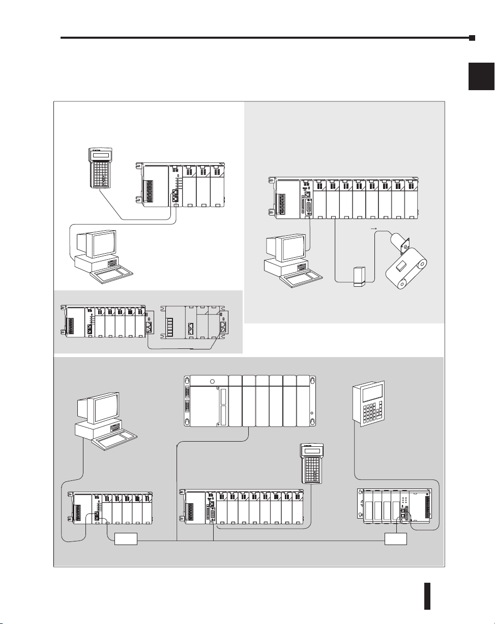
Chapter 1: Getting Started
Getting Started
Networking
RS232C
(max.50ft/16.2m)
RS232C
(max.50ft/16.2m)
(max.
6.5ft / 2m)
Handheld Programmer
Operator Interface
Programming or
Computer Interface
Simple Motion Control
Flexible solutions in one package
High-speed counting (up to 100 KHz)
Pulse train output (up to 50KHz
High–speed Edge timing
Machine
Control
Packaging
Conveyors
Elevators
Programming or
Computer Interface
RS232C
(max.50ft/16.2m)
Handheld
Programmer
DL240
RS232/422
Convertor
RS232/422
Convertor
Simple programming
through the RLL Program
DL260 with H2–CTRIO(2) High Speed I/O Module
DL240
DL250–1 or DL260
DL305
Pulse
Output
Drive
Amplifier
Stepper Motor
Local I/O Expansion
DCM
DL205 System Diagrams
The diagram below shows the major components and configurations of the DL205 system.
The next two pages show specific components for building your system.
1
2
3
4
5
6
7
8
9
10
11
12
13
14
A
DL205 User Manual, 4th Edition, Rev. B
B
C
D
1–5
Page 31
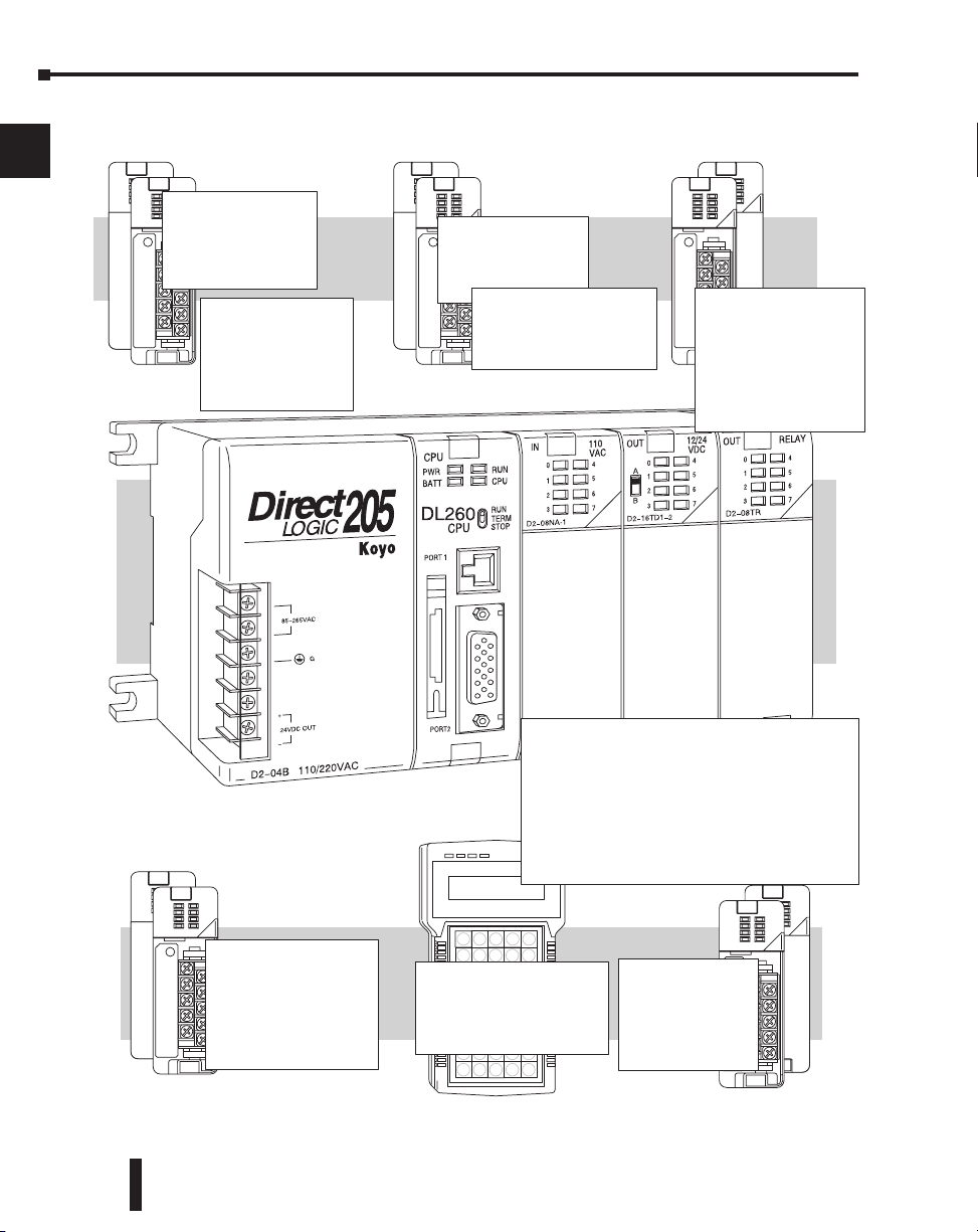
Chapter 1: Getting Started
PROGRAMMING
Handheld Programmer
with Built-in RLL
PLUS
Direct SOFT Programming
for Windows
AC INPUT
8pt110 VA C
16pt110 VA C
Direct LOGIC DL205 Family
DC INPUT
8pt12–24 VDC
16pt 24 VDC
32pt 24 VDC
32pt 5–15 VDC
SPECIALTY MODULES
High Speed Counters
CPU Slot Controllers
Remote Masters
Remote Slaves
Communications
Temperature Input
Filler Module
AC OUTPUT
8pt18–220 VAC
12pt18–110 VAC
2 commons
RELAY OUTPUT
4pt 5–30 VDC
5–240VAC
8pt 5–30 VDC
5 –240 VAC
12pt 5–30VDC
5–240VAC
(isolated pts.module
available)
ANALOG
CPUs
DL230 – 2.0K Built-in EEPROM Memory
DL240 – 2.5K Built-in EEPROM Memory
DL250–1 – 7.6K Built-in Flash Memory
DL260 – 15.8K Built-in Flash Memory
BASES
3 Slot Base, 110/220VAC, 24VDC
4 Slot Base, 110/220VAC, 24VDC
6 Slot Base, 110/220VAC, 24VDC, 125 VDC
9 Slot Base, 110/220VAC, 24VDC, 125 VDC
DC OUTPUT
4pt12–24 VDC
8pt12–24 VDC
16pt12–24 VDC
2 Commons
32pt12–24 VDC
4 Commons
4CH INPUT
8CH INPUT
2CH OUTPUT
8CH OUTPUT
4 IN/2 OUT
8 IN/4 OUT
ANALOG
1
2
3
4
5
6
7
8
9
10
11
12
13
14
A
B
C
D
1–6
DL205 User Manual, 4th Edition, Rev. B
Page 32

Programming Methods
There are two programming methods available for the DL205 CPUs, RLL (Relay Ladder
Logic) and RLL
the handheld programmer support RLL and Stage.
DirectSOFT Programming for Windows.
The DL205 can be programmed with one of the most advanced programming packages in
the industry ––DirectSOFT5. DirectSOFT5 is a Windows-based software package that
supports many Windows features you already know, such as cut and paste between
applications, point and click editing, viewing and editing multiple application programs at
the same time, etc. DirectSOFT5 universally supports the DirectLOGIC CPU families. This
means you can use the same DirectSOFT5 package to program DL05, DL06, DL105,
DL205, DL305, DL405 or any new CPUs we may add to our product line. There is a
separate manual that discusses the DirectSOFT5 programming software which is included
with your software package.
Handheld Programmer
All DL205 CPUs have a built-in programming port for use with the handheld programmer
(D2–HPP). The handheld programmer can be used to create, modify and debug your
application program. A separate manual that discusses the DL205 Handheld Programmer is
available.
PLUS
(Stage Programming). Both the DirectSOFT5 programming package and
Chapter 1: Getting Started
1
2
3
4
5
6
7
8
9
DL205 User Manual, 4th Edition, Rev. B
10
11
12
13
14
A
B
C
D
1–7
Page 33
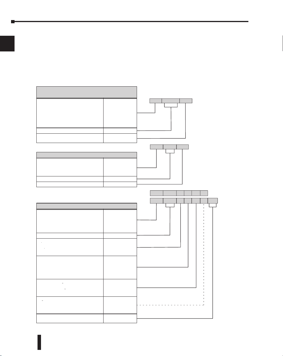
Chapter 1: Getting Started
CPUs
Specialty CPUs
DL05/06 Product family
DL105 Product family
DL205 Product family
DL305 Product family
DL405 Product family
D0/F0
D1/F1
D2/F2
D3/F3
D4/F4
Class of CPU / Abbreviation 230...,330...,430...
Denotes a differentiation between
similar modules
–1, –2, –3, –4
Bases
D2/F2
D3/F3
D4/F4
Number of slots ##B
Type of Base DC or empty
Discrete I/O
Number of points 04/08/12/16/32/64
Input N
Input
Output
N
T
Output
Combination
T
C
AC A
ACDCA
D
DC
Either
D
E
Either
Relay
E
R
Current Sinking 1
Current Sinking
Current Sourcing
1
2
Current Sourcing
Current Sinking/Sourcing
2
3
High Current H
High Current
Isolation
H
S
Isolation
Fast I/O
S
F
Denotes a differentiation between
similar modules
–1, –2, –3, –4
D3– 16 N D 2 –1
D4– 16 N D 2 F
D3– 05B DC
D4– 440DC –1
DL205 Product family
DL305 Product family
DL405 Product family
DL05/06 Product family
DL205 Product family
DL305 Product family
DL405 Product family
D0/F0
D2/F2
D3/F3
D4/F4
DirectLOGIC™ Part Numbering System
1
2
3
As you examine this manual, you will notice there are many different products available.
Sometimes it is difficult to remember the specifications for any given product. However, if
you take a few minutes to understand the numbering system, it may save you some time and
confusion. The charts below show how the part numbering systems work for each product
category. Part numbers for accessory items such as cables, batteries, memory cartridges, etc.,
are typically an abbreviation of the description for the item.
4
5
6
7
8
9
10
11
12
13
14
A
B
C
D
1–8
DL205 User Manual, 4th Edition, Rev. B
Page 34
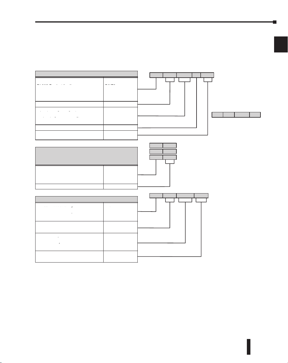
Chapter 1: Getting Started
Analog I/O
DL05/06 Product family
D0/F0
DL205 Product family
D2/F2
DL305 Product family
DL405 Product family
D3/F3
D4/F4
Number of channels 02/04/08/16
Input (Analog to Digital) AD
Input (Analog to Digital)
Output (Digital to Analog)
AD
DA
Output (Digital to Analog)
Combination
DA
AND
Isolated S
Denotes a differentiation between
Similar modules
–1, –2, –3, –4
Communication and Networking
Special I/O and Devices
Programming
DL205 Product family
DL305 Product family
DL405 Product family
D2/F2
D3/F3
D4/F4
Name Abbreviation see example
CoProcessors and ASCII BASIC Modules
DL205 Product family D2/F2
DL205 Product family
DL305 Product family
D2/F2
D3/F3
DL305 Product family
DL405 Product family
D3/F3
D4/F4
CoProcessor CP
CoProcessor
ASCII BASIC
CP
AB
64K memory 64
64K memory
128K memory
64
128
128K memory
512K memory
128
512
Radio modem R
Radio modem
Telephone modem
R
T
F4– CP 128 – R
F3– 04 AD S –1
F3– 08 THM –n
note: –n indicates thermocouple type
Alternate example of Analog I/O
such as: J, K, T, R, S or E
using abbreviations
D3– HPP
D3– HSC
D4– DCM
HPP (RLL PLUS Handheld Programmer)
HSC (High Speed Counter)
DCM (Data Communication Module)
1
2
3
4
5
6
7
8
DL205 User Manual, 4th Edition, Rev. B
9
10
11
12
13
14
A
B
C
D
1–9
Page 35
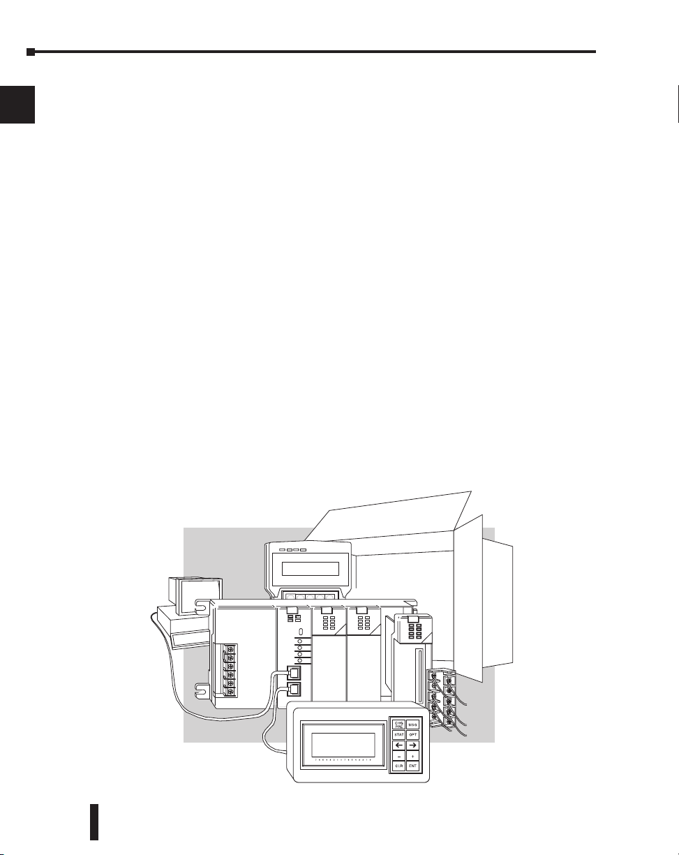
Chapter 1: Getting Started
Quick Start for PLC Validation and Programming
1
2
3
4
5
6
7
8
9
10
If you have experience using PLCs, or want to setup a quick example, this section is what you
want to use. This example is not intended to explain everything needed to start-up your
system. It is only intended to provide a general picture of what is needed to get your system
powered-up.
Step 1: Unpack the DL205 Equipment
Unpack the DL205 equipment and verify you have the parts necessary to build this
demonstration system. The minimum parts needed are as follows:
• Base
• CPU
• A discrete input module such as a D2–16ND3–2 DC or a F2–08SIM input simulator module
• A discrete output module such as a D2–16TD1–2 DC
• *Power cord
• *Hook up wire
• *One or more toggle switches (if not using the input simulator module)
• *A screwdriver, blade or Phillips type
*These items are not supplied with your PLC.
You will need at least one of the following programming options:
• DirectSOFT5 Programming Software, DirectSOFT5 Manual, and a programming cable
(connects the CPU to a personal computer), or
• D2–HPP Handheld Programmer and the Handheld Programmer Manual.
11
12
13
14
A
B
C
D
1–10
DL205 User Manual, 4th Edition, Rev. B
Page 36

Chapter 1: Getting Started
Toggle switch
Input
Module
Output
Module
Step 2: Install the CPU and I/O Modules
Insert the CPU and I/O into the base. The CPU
must be inserted into the first slot of the base
(next to the power supply).
• Each unit has a plastic retaining clip at the top and
bottom. Slide the retainer clips to the out position
before installing the module.
• With the unit square to the base, slide it in using
the upper and lower guides.
• Gently push the unit back until it is firmly seated in the backplane.
• Secure the unit to the base by pushing in the retainer clips.
Placement of discrete, analog and relay modules are not critical and may go in any slot in any
base, however for this example, install the output module in the slot next to the CPU and the
input module in the next. Limiting factors for other types of modules are discussed in
Chapter 4, System Design and Configuration. You must also make sure you do not exceed
the power budget for each base in your system configuration. Power budgeting is also
discussed in Chapter 4.
Step 3: Remove Terminal Strip Access Cover
Remove the terminal strip cover. It is a small
strip of clear plastic that is located on the base
power supply.
Step 4: Add I/O Simulation
To finish this quick start exercise or study other examples in this manual, you will need to
install an input simulator module (or wire an input switch as shown below), and add an
output module. Using an input simulator is the quickest way to get physical inputs for
checking out the system or a new program. To monitor output status, any discrete output
module will work.
Lift off
Retaining Clips
CPU must reside in first slot!
1
2
3
4
5
6
7
8
9
10
11
12
Wire the switches or other field devices prior to applying power to the system to ensure a
point is not accidentally turned on during the wiring operation. This example uses DC input
and output modules. Wire the input module, X0, to the toggle switch and 24VDC auxiliary
power supply on the CPU terminal strip as shown. Chapter 2, Installation, Wiring, and
Specifications provides a list of I/O wiring guidelines.
DL205 User Manual, 4th Edition, Rev. B
13
14
A
B
C
D
1–11
Page 37
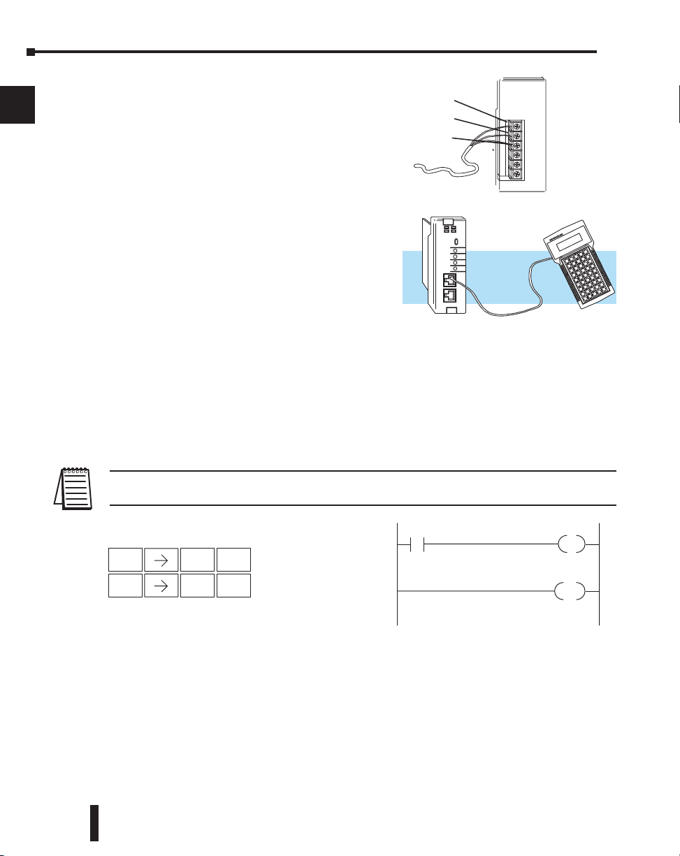
Chapter 1: Getting Started
Ground
Line
Neutral
Y0
X0
END
STR
$
1
B
ENT
OUT
GX
2
C
ENT
Handheld Program Keystrokes
Step 5: Connect the Power Wiring
1
2
3
4
5
6
7
8
9
10
Connect the wires as shown. Observe all precautions
stated earlier in this manual. For details on wiring see
Chapter 2 Installation, Wiring, and Specifications.
When the wiring is complete, replace the CPU and
module covers. Do not apply power at this time.
Step 6: Connect the Programmer
Either connect the programming cable connected to
a computer loaded with DirectSOFT Programming
Software or a D2-HPP Handheld Programmer
(comes with programming cable) to the top port of
the CPU.
Step 7: Switch On the System Power
Apply power to the system and ensure the PWR
indicator on the CPU is on. If not, remove power
from the system, check all wiring and refer to the troubleshooting section in Chapter 9 for
assistance.
Step 8: Enter the Program
Slide the switch on the CPU to the STOP position (250–1 / 260 only) and then back to the
TERM position. This puts the CPU in the program mode and allows access to the CPU
program. Edit a DirectSOFT program using the relay ladder diagram below and load it into
the PLC. If using an HPP, the PGM indicator should be illuminated on the HPP. Enter the
following keystrokes on the HPP:
11
12
13
14
A
B
C
D
1–12
NOTE: It is not necessary for you to configure the I/O for this system since the DL205 CPUs automatically
examine any installed modules and establish the correct configuration.
After entering the example program put the CPU in the RUN mode with DirectSOFT or
after entering the program using the HPP, slide the switch from the TERM position to the
RUN position and back to TERM. The RUN indicator on the CPU will come on indicating
the CPU has entered the run mode. If not repeat Step 8 insuring the program is entered
properly or refer to the troubleshooting guide in chapter 9.
During Run mode operation, the output status indicator “0” on the output module should
reflect the switch status. When the switch is on the output should be on.
DL205 User Manual, 4th Edition, Rev. B
Page 38

Steps to Designing a Successful System
Power up
Initialize hardware
Check I/O module
config. and verify
16pt
Input
8pt
Input
X0
-
X17
-
X20
X27
8pt
Output
Y0
-
Y7
Step 1: Review the Installation Guidelines
Always make safety your first priority in any system
application. Chapter 2 provides several guidelines that will
help provide a safer, more reliable system. This chapter also
includes wiring guidelines for the various system
components.
Chapter 1: Getting Started
1
2
3
4
Step 2: Understand the CPU Setup Procedures
The CPU is the heart of your automation system and is
explained in Chapter 3. Make sure you take time to
understand the various features and setup requirements.
Step 3: Understand the I/O System
Configurations
It is important to understand how your local
I/O system can be configured. It is also
important to understand how the system
Power Budget is calculated. This can affect
your I/O placement and/or configuration
options. See Chapter 4 for more information.
Step 4: Determine the I/O Module Specifications and
Wiring Characteristics
There are many different I/O modules available with the DL205
system. Chapter 2 provides the specifications and wiring diagrams
for the discrete I/O modules.
NOTE: Analog and specialty modules have their own manuals and are not included in this manual.
5
6
7
8
9
10
11
12
13
14
A
Step 5: Understand the System Operation
Before you begin to enter a program, it is very helpful to
understand how the DL205 system processes information.
This involves not only program execution steps, but also
involves the various modes of operation and memory layout
characteristics. See Chapter 3 for more information.
DL205 User Manual, 4th Edition, Rev. B
B
C
D
1–13
Page 39

Chapter 1: Getting Started
Standard RLL Programming
(see Chapter 5)
X0
LDD
V1076
CMPD
K309482
SP62
OUT
Y0
Timer/Event Drum Sequencer
(see Chapter 6)
Push–UP
UP
Push–
DOWN
DOWN
LOWER
RAISE
LIGHT
Stage Programming
(see Chapter 7)
PID Loop Operation
(see Chapter 8)
PV
PID Process
SP
k?
+
–
TMR T1
K30
CNT CT3
K10
Step 6: Review the Programming Concepts
The DL205 provides four main approaches to solving the application program, including the
1
2
3
4
5
PID loop task depicted in the next figure.
• RLL diagram style programming is the best tool for solving boolean logic and general CPU register/
accumulator manipulation. It includes dozens of instructions, which will augment drums, stages
and loops.
• The DL250-1 and DL260 have four timer/event drum types, each with up to 16 steps. They offer
both time and/or event-based step transitions. Drums are best for a repetitive process based on a
single series of steps.
• Stage programming, called RLL
program into sections which correspond to the states in a flow chart of your process.
• The DL260 PID loop operation uses setup tables to configure 16 loops. The DL250-1 PID loop
operation uses setup to configure 4 loops. Features include: auto tuning, alarms, SP ramp/soak
generation and more.
6
7
8
9
PLUS
, is based on state-transition diagrams. Stages divide the ladder
10
11
12
13
Step 7: Choose the Instructions
14
A
B
C
D
1–14
Once you have installed the system and understand
the theory of operation, you can choose from one
of the most powerful instruction sets available.
Step 8: Understand the Maintenance and
Troubleshooting Procedures
Equipment failures can occur at any time. Switches
fail, batteries need to be replaced, etc. In most
cases, the majority of the troubleshooting and
maintenance time is spent trying to locate the
problem. The DL205 system has many built-in
features that help you quickly identify problems.
Refer to Chapter 9 for diagnostics.
DL205 User Manual, 4th Edition, Rev. B
Page 40

INSTALLATION, WIRING
CHAPTER
CHAPTER
CHAPTER
AND
In This Chapter:
SPECIFICATIONS
22
22
Safety Guidelines . . . . . . . . . . . . . . . . . . . . . . . . . . . . . . . . . . . . . . .2–2
Mounting Guidelines . . . . . . . . . . . . . . . . . . . . . . . . . . . . . . . . . . . .2–5
Installing DL205 Bases . . . . . . . . . . . . . . . . . . . . . . . . . . . . . . . . . .2–10
Installing Components in the Base . . . . . . . . . . . . . . . . . . . . . . . . .2–12
Base Wiring Guidelines . . . . . . . . . . . . . . . . . . . . . . . . . . . . . . . . . .2–13
I/O Wiring Strategies . . . . . . . . . . . . . . . . . . . . . . . . . . . . . . . . . . .2–14
I/O Modules Position, Wiring, and Specification . . . . . . . . . . . . . .2–26
Glossary of Specification Terms . . . . . . . . . . . . . . . . . . . . . . . . . . .2–51
Page 41
Chapter 2: Installation, Wiring and Specifications
Safety Guidelines
1
NOTE: Products with CE marks perform their required functions safely and adhere to relevant standards as
2
3
specified by CE directives, provided they are used according to their intended purpose and that the
instructions in this manual are adhered to. The protection provided by the equipment may be impaired if
this equipment is used in a manner not specified in this manual. A listing of our international affiliates is
available on our Web site: http://www.automationdirect.com
4
5
6
7
8
9
10
11
12
13
14
A
B
C
D
WARNING: Providing a safe operating environment for personnel and equipment is your responsibility
and should be your primary goal during system planning and installation. Automation systems can fail
and may result in situations that can cause serious injury to personnel and/or damage equipment. Do
not rely on the automation system alone to provide a safe operating environment. Sufficient emergency
circuits should be provided to stop either partially or totally the operation of the PLC or the controlled
machine or process. These circuits should be routed outside the PLC in the event of controller failure,
so that independent and rapid shutdown are available. Devices, such as “mushroom” switches or end
of travel limit switches, should operate motor starter, solenoids, or other devices without being
processed by the PLC. These emergency circuits should be designed using simple logic with a
minimum number of highly reliable electromechanical components. Every automation application is
different, so there may be special requirements for your particular application. Make sure all national,
state, and local government requirements are followed for the proper installation and use of your
equipment.
Plan for Safety
The best way to provide a safe operating environment is to make personnel and equipment
safety part of the planning process. You should examine every aspect of the system to
determine which areas are critical to operator or machine safety.
If you are not familiar with PLC system installation practices, or your company does not have
established installation guidelines, you should obtain additional information from the
following sources.
• NEMA — The National Electrical Manufacturers Association, located in Washington,
D.C., publishes many different documents that discuss standards for industrial control
systems. You can order these publications directly from NEMA. Some of these include:
ICS 1, General Standards for Industrial Control and Systems
ICS 3, Industrial Systems
ICS 6, Enclosures for Industrial Control Systems
• NEC — The National Electrical Code provides regulations concerning the installation and
use of various types of electrical equipment. Copies of the NEC Handbook can often be
obtained from your local electrical equipment distributor or your local library.
• Local and State Agencies — many local governments and state governments have additional
requirements above and beyond those described in the NEC Handbook. Check with your
local Electrical Inspector or Fire Marshall office for information.
2–2
DL205 User Manual, 4th Edition, Rev. B
Page 42
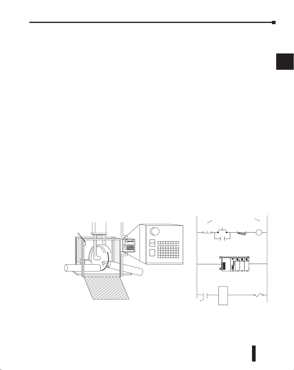
Chapter 2: Installation, Wiring and Specifications
Output
Module
Saw
Arbor
E STOP
Master
Relay
Emergency
Stop
Power On
Master Relay Contacts
To disconnect output
module power
Use E-Stop and Master Relay
Guard
Limit
Guard Limit Switch
Master
Relay
Contacts
Three Levels of Protection
The publications mentioned provide many ideas and requirements for system safety. At a
minimum, you should follow these regulations. Also, you should use the following
techniques, which provide three levels of system control.
• Emergency stop switch for disconnecting system power
• Mechanical disconnect for output module power
• Orderly system shutdown sequence in the PLC control program
Emergency Stops
It is recommended that emergency stop circuits be incorporated into the system for every
machine controlled by a PLC. For maximum safety in a PLC system, these circuits must not
be wired into the controller, but should be hardwired external to the PLC. The emergency
stop switches should be easily accessed by the operator and are generally wired into a master
control relay (MCR) or a safety control relay (SCR) that will remove power from the PLC
I/O system in an emergency.
MCRs and SCRs provide a convenient means for removing power from the I/O system
during an emergency situation. By de-energizing an MCR (or SCR) coil, power to the input
(optional) and output devices is removed. This event occurs when any emergency stop switch
opens. However, the PLC continues to receive power and operate even though all its inputs
and outputs are disabled.
The MCR circuit could be extended by placing a PLC fault relay (closed during normal PLC
operation) in series with any other emergency stop conditions. This would cause the MCR
circuit to drop the PLC I/O power in case of a PLC failure (memory error, I/O
communications error, etc.).
1
2
3
4
5
6
7
8
9
10
11
DL205 User Manual, 4th Edition, Rev. B
12
13
14
A
B
C
D
2–3
Page 43
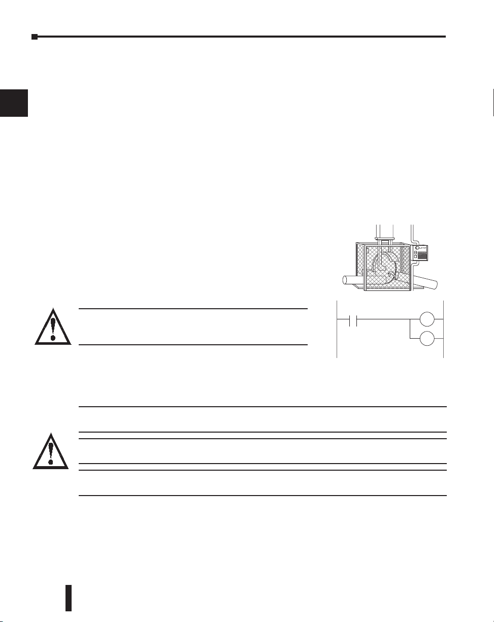
Chapter 2: Installation, Wiring and Specifications
Turn off
Saw
Jam
Detect
RST
RST
Retract
Arm
Emergency Power Disconnect
1
2
3
4
5
6
7
8
A properly rated emergency power disconnect should be used to power the PLC controlled
system as a means of removing the power from the entire control system. It may be necessary
to install a capacitor across the disconnect to protect against a condition known as “outrush”.
This condition occurs when the output Triacs are turned off by powering off the disconnect,
thus causing the energy stored in the inductive loads to seek the shortest distance to ground,
which is often through the Triacs.
After an emergency shutdown or any other type of power interruption, there may be
requirements that must be met before the PLC control program can be restarted. For
example, there may be specific register values that must be established (or maintained from
the state prior to the shutdown) before operations can resume. In this case, you may want to
use retentive memory locations, or include constants in the control program to insure a
known starting point.
Orderly System Shutdown
Ideally, the first level of fault detection is the PLC control
program, which can identify machine problems. Certain
shutdown sequences should be performed. The types of
problems are usually things such as jammed parts, etc.
that do not pose a risk of personal injury or equipment
damage.
9
10
11
12
13
14
A
B
C
D
2–4
WARNING: The control program must not be the only form of
protection for any problems that may result in a risk of personal
injury or equipment damage.
Class 1, Division 2, Approval
This equipment is suitable for use in Class 1, Division 2, Zone 2, groups A, B, C and D or
non-hazardous locations only.
WARNING: Explosion Hazard! Substitution of components may impair suitability for Class 1, Division 2,
Zone 2.
WARNING: Explosion Hazard - Do not disconnect equipment unless power has been switched off or the
area is known to be non-hazardous.
WARNING: All DL205 products used with connector accessories must use R/C (ECBT2) mating plugs. All
mating plugs must have suitable ratings for the devices.
DL205 User Manual, 4th Edition, Rev. B
Page 44

Mounting Guidelines
B
A
C
2.99”
(76mm)
3.54”
(90mm)
DIN Rail slot. Use rail conforming to
DIN EN 50022.
2.95”
(75mm)
3.62”
(92mm)
12 or 16pt I/O
4 or 8pt . I/O
D
with D2–EM Expansion Unit
4.45”
(113mm)
32pt.
ZIPLink cable or
base exp. unit cable
5.85”
(148mm)
D2–DSCBL–1
on port 2
Mounting depths with:
Before installing the PLC system you will need to know the dimensions of the components
considered. The diagrams on the following pages provide the component dimensions to use
in defining your enclosure specifications. Remember to leave room for potential expansion.
NOTE: If you are using other components in your system, refer to the appropriate manual to determine
how those units can affect mounting dimensions.
Chapter 2: Installation, Wiring and Specifications
1
2
3
Base Dimensions
The following information shows the proper mounting dimensions. The height dimension is
the same for all bases. The depth varies depending on your choice of I/O module. The length
varies as the number of slots increase. Make sure you have followed the installation guidelines
for proper spacing.
4
5
6
7
8
9
10
11
12
13
14
3-slot 6.77” 172mm 6.41” 163mm 5.8” 148mm 7.24” 184mm
4-slot 7.99” 203mm 7.63” 194mm 7.04” 179mm 8.46” 215mm
6-slot 10.43” 265mm 10.07” 256mm 9.48” 241mm 10.90” 277mm
9-slot 14.09” 358mm 13.74” 349mm 13.14” 334mm 14.56” 370mm
Base
(Base Total Width) B (Mounting Hole) C (Component Width) D (Width with Exp. Unit)
Inches Millimeters Inches Millimeters Inches Millimeters Inches Millimeters
A
DL205 User Manual, 4th Edition, Rev. B
A
B
C
D
2–5
Page 45
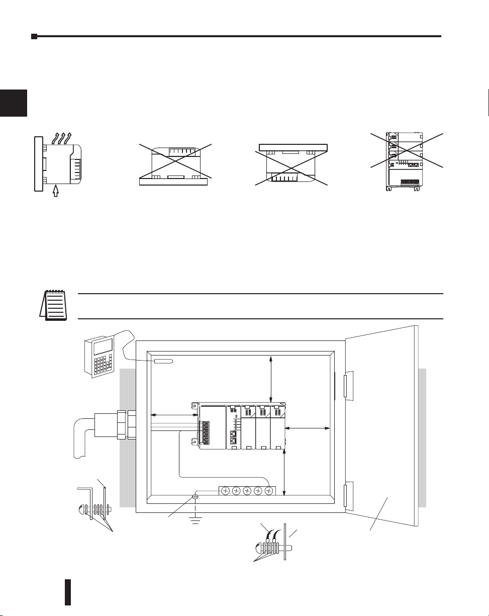
Chapter 2: Installation, Wiring and Specifications
OK
Airflow
Safety Guidelines
Earth Ground
Panel Ground
T
erminal
DL205 CPU Base
Power
Source
Temperature
Probe
Star Washers
Panel
Ground Braid
Copper Lugs
Panel or
Single Point
Ground
Star Washers
BUS Bar
Note: there is a minimum of 2” (50mm)
clearance between the panel door
or any devices mounted in the panel door
2”
50mm
min.
2”
50mm
min.
and the nearest DL205 component
2”
50mm
min.
2”
50mm
min.
Panel Mounting and Layout
1
2
It is important to design your panel properly to help ensure the DL205 products operate
within their environmental and electrical limits. The system installation should comply with
all appropriate electrical codes and standards. It is important the system also conforms to the
operating standards for the application to insure proper performance. The diagrams below
reference the items in the following list.
3
4
5
6
7
8
9
10
11
12
13
14
A
B
1. Mount the bases horizontally to provide proper ventilation.
2. If you place more than one base in a cabinet, there should be a minimum of 7.2” (183mm)
between bases.
3. Provide a minimum clearance of 2” (50mm) between the base and all sides of the cabinet. There
should also be at least 1.2” (30mm) of clearance between the base and any wiring ducts.
4. There must be a minimum of 2” (50mm) clearance between the panel door and the nearest DL205
component.
NOTE: The cabinet configuration below is not suitable for EU installations.
Refer to Appendix I European Union Directives.
C
D
2–6
DL205 User Manual, 4th Edition, Rev. B
Page 46

Chapter 2: Installation, Wiring and Specifications
5. The ground terminal on the DL205 base must be connected to a single point ground. Use copper
stranded wire to achieve a low impedance. Copper eye lugs should be crimped and soldered to the
ends of the stranded wire to ensure good surface contact. Remove anodized finishes and use copper
lugs and star washers at termination points. A general rule is to achieve a 0.1 ohm of DC resistance
between the DL205 base and the single point ground.
6. There must be a single point ground (i.e. copper bus bar) for all devices in the panel requiring an
earth ground return. The single point of ground must be connected to the panel ground
termination. The panel ground termination must be connected to earth ground. For this
connection you should use #12 AWG stranded copper wire as a minimum. Minimum wire sizes,
color coding, and general safety practices should comply with appropriate electrical codes and
standards for your region. A good common ground reference (Earth ground) is essential for proper
operation of the DL205. There are several methods of providing an adequate common ground
reference, including:
a) Installing a ground rod as close to the panel as possible.
b) Connection to incoming power system ground.
7. Properly evaluate any installations where the ambient temperature may approach the lower or
upper limits of the specifications. Place a temperature probe in the panel, close the door and
operate the system until the ambient temperature has stabilized. If the ambient temperature is not
within the operating specification for the DL205 system, measures such as installing a
cooling/heating source must be taken to get the ambient temperature within the DL205 operating
specifications.
8. Device mounting bolts and ground braid termination bolts should be #10 copper bolts or
equivalent. Tapped holes instead of nut–bolt arrangements should be used whenever possible. To
ensure good contact on termination areas impediments such as paint, coating or corrosion should
be removed in the area of contact.
9. The DL205 system is designed to be powered by 110/220 VAC, 24 VDC, or 125 VDC normally
available throughout an industrial environment. Electrical power in some areas where the PLCs are
installed is not always stable and storms can cause power surges. Due to this, powerline filters are
recommended for protecting the DL205 PLCs from power surges and EMI/RFI noise. The
Automation Powerline Filter, for use with 120 VAC and 240 VAC, 1–5 Amps, is an excellent
choice (can be located at www.automationdirect.com), however, you can use a filter of your choice.
These units install easily between the power source and the PLC.
Enclosures
Your selection of a proper enclosure is important to ensure safe and proper operation of your
DL205 system. Applications of DL205 systems vary and may require additional features. The
minimum considerations for enclosures include:
• Conformance to electrical standards
• Protection from the elements in an industrial environment
• Common ground reference
• Maintenance of specified ambient temperature
• Access to equipment
• Security or restricted access
• Sufficient space for proper installation and maintenance of equipment
1
2
3
4
5
6
7
8
9
10
11
12
13
14
A
B
C
D
DL205 User Manual, 4th Edition, Rev. B
2–7
Page 47

Chapter 2: Installation, Wiring and Specifications
Environmental Specifications
1
2
3
Storage temperature
4
Ambient operating temperature*
Ambient humidity**
Vibration resistance
5
Shock resistance
Noise immunity
6
Atmosphere
* Operating temperature for the Handheld Programmer and the DV-1000 is 32° to 122° F (0° to 50° C) Storage temperature
7
8
for the Handheld Programmer and the DV-1000 is - 4° to 158° F (- 20° to 70° C).
** Equipment will operate below 30% humidity. However, static electricity problems occur much more frequently at lower
humidity levels. Make sure you take adequate precautions when you touch the equipment. Consider using ground
straps, anti-static floor coverings, etc., if you use the equipment in low humidity environments.
9
The following table lists the environmental specifications that generally apply to the DL205
system (CPU, Bases, I/O Modules). The ranges that vary for the Handheld Programmer are
noted at the bottom of this chart. I/O module operation may fluctuate depending on the
ambient temperature and your application. Please refer to the appropriate I/O module
specifications for the temperature derating curves applying to specific modules.
Specification Rating
–4° F to 158° F (–20° C to 70° C)
32° F to 131° F (0° C to 55° C)
30% – 95% relative humidity (non–condensing)
MIL STD 810C, Method 514.2
MIL STD 810C, Method 516.2
NEMA (ICS3–304)
No corrosive gases
Power
The power source must be capable of supplying voltage and current complying with the base
power supply specifications.
10
Specification AC Powered Bases 24 VDC Powered Bases 125 VDC Powered Bases
11
Part Numbers
12
Input Voltage Range
Maximum Inrush Current
13
Maximum Power
Voltage Withstand (dielectric)
14
Insulation Resistance
Auxiliary 24 VDC Output
A
Fusing (internal to base power
supply)
D2–03B–1,
D2–04B–1,
D2–06B–1
D2–09B–1
100–240 VAC (+10%/ –15%)
50/60 Hz
30A 10A 20A
80VA 25W 30W
1 minute @ 1500 VAC between primary, secondary, and field ground
> 10 MΩ at 500 VDC
20–28 VDC, less than 1V p-p
300mA max.
Non–replaceable 2A @ 250V
slow blow fuse
D2–03BDC1–1,
D2–04BDC1–1,
D2–06BDC1–1,
D2–09BDC1–1
10.2 – 28.8VDC (24VDC) with
less than 10% ripple
None
Non–replaceable 3.15A @
250V slow blow fuse
D2–06BDC2–1,
D2–09BDC2–1
104–240 VDC
+10% –15%
20–28 VDC, less than 1V p-p
300mA max.
Non–replaceable 2A @ 250V
slow blow fuse
B
C
D
2–8
DL205 User Manual, 4th Edition, Rev. B
Page 48

Chapter 2: Installation, Wiring and Specifications
Marine Use
American Bureau of Shipping (ABS) certification requires flame-retarding insulation as per
4-8-3/5.3.6(a). ABS will accept Navy low smoke cables, cable qualified to NEC “Plenum
rated” (fire resistant level 4), or other similar flammability resistant rated cables. Use cable
specifications for your system that meet a recognized flame retardant standard (i.e. UL, IEEE,
etc.), including evidence of cable test certification (i.e. tests certificate, UL file number, etc.).
NOTE: Wiring needs to be “low smoke” per the above paragraph. Teflon coated wire is also recommended.
Agency Approvals
Some applications require agency approvals. Typical agency approvals which your application
may require are:
• UL (Underwriters’ Laboratories, Inc.)
• CSA (Canadian Standards Association)
• FM (Factory Mutual Research Corporation)
• CUL (Canadian Underwriters’ Laboratories, Inc.)
24 VDC Power Bases
Follow these additional installation guidelines when installing D2-03BDC1-1, D2-04BDC11, D2-06BDC1-1 and D2-09BDC1-1 bases:
• Install these bases in compliance with the enclosure, mounting, spacing, and segregation
requirements of the ultimate application.
• These bases must be used within their marked ratings.
• These bases are intended to be installed within an enclosure rated at least IP54.
• Provesions should be made to prevent the rated voltage being exceeded by transient disturbances of
more than 40%.
1
2
3
4
5
6
7
8
9
10
11
DL205 User Manual, 4th Edition, Rev. B
12
13
14
A
B
C
D
2–9
Page 49
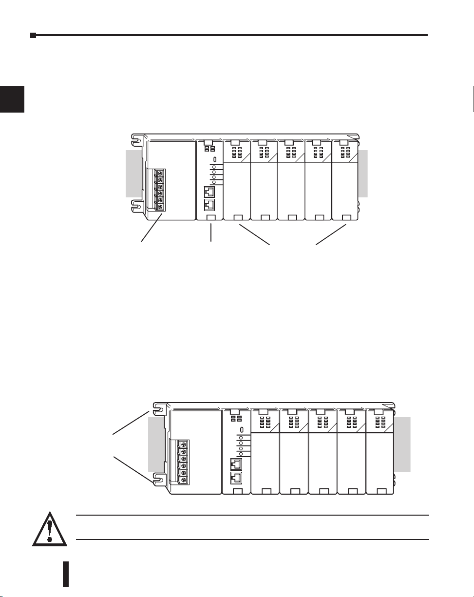
Chapter 2: Installation, Wiring and Specifications
Power Wiring
Connections
CPU Slot
I/O Slots
Mounting Tabs
Installing DL205 Bases
1
Choosing the Base Type
2
3
The DL205 system offers four different sizes of bases and three different power supply
options.
The following diagram shows an example of a 6-slot base.
4
5
6
7
8
9
10
11
Mounting the Base
12
13
14
A
B
C
D
Your choice of base depends on three things:
• Number of I/O modules required
• Input power requirement (AC or DC power)
• Available power budget
All I/O configurations of the DL205 may use any of the base configurations. The bases are
secured to the equipment panel or mounting location using four M4 screws in the corner tabs
of the base. The full mounting dimensions are given in the previous section on Mounting
Guidelines.
WARNING: To minimize the risk of electrical shock, personal injury, or equipment damage, always
disconnect the system power before installing or removing any system component.
2–10
DL205 User Manual, 4th Edition, Rev. B
Page 50
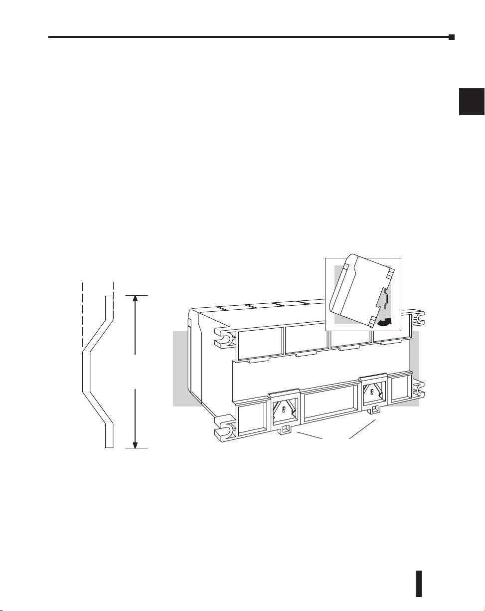
Chapter 2: Installation, Wiring and Specifications
35 mm
7.5mm
Retaining Clips
DIN Rail Dimensions
Using Mounting Rails
The DL205 bases can also be secured to the cabinet by using mounting rails. You should use
rails that conform to DIN EN standard 50 022. Refer to our catalog for a complete line of
DIN rail, DINnectors and DIN rail mounted apparatus. These rails are approximately 35mm
high, with a depth of 7.5mm. If you mount the base on a rail, you should also consider using
end brackets on each end of the rail. The end brackets help keep the base from sliding
horizontally along the rail. This helps minimize the possibility of accidentally pulling the
wiring loose.
If you examine the bottom of the base, you’ll notice small retaining clips. To secure the base
to a DIN rail, place the base onto the rail and gently push up on the retaining clips. The clips
lock the base onto the rail.
To remove the base, pull down on the retaining clips, lift up on the base slightly, and pull it
away from the rail.
1
2
3
4
5
6
7
8
9
DL205 User Manual, 4th Edition, Rev. B
10
11
12
13
14
A
B
C
D
2–11
Page 51
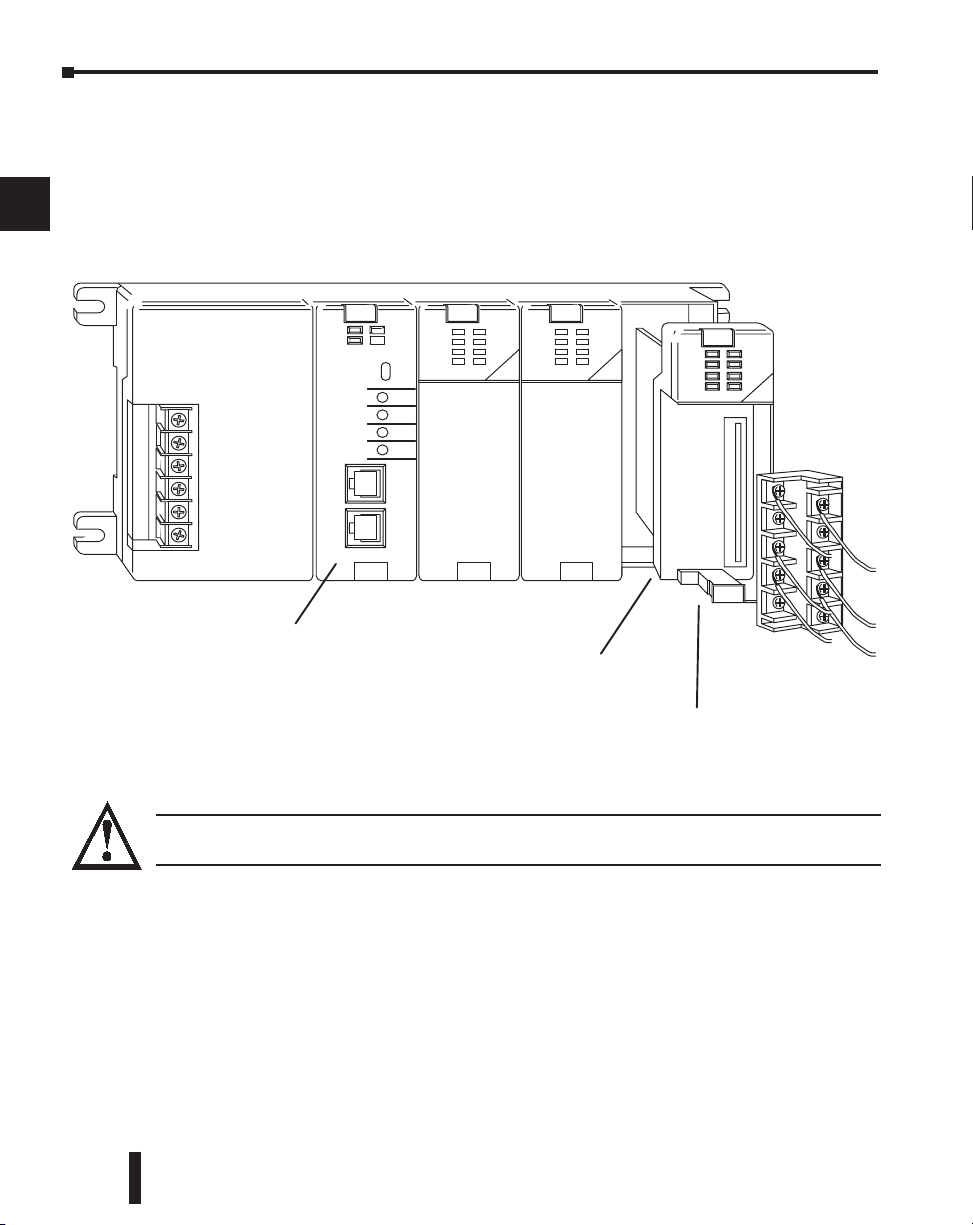
Chapter 2: Installation, Wiring and Specifications
Align module PC board to
slots in base and slide in
Push the retaining
clips in to secure the module
to the DL205 base
CPU must be positioned in
the first slot of the base
Installing Components in the Base
1
2
3
To insert components into the base: first slide the module retaining clips to the out position
and align the PC board(s) of the module with the grooves on the top and bottom of the base.
Push the module straight into the base until it is firmly seated in the backplane connector.
Once the module is inserted into the base, push in the retaining clips to firmly secure the
module to the base.
4
5
6
7
8
9
10
11
12
13
WARNING: Minimize the risk of electrical shock, personal injury, or equipment damage. Always
14
disconnect the system power before installing or removing any system component.
A
B
C
D
2–12
DL205 User Manual, 4th Edition, Rev. B
Page 52
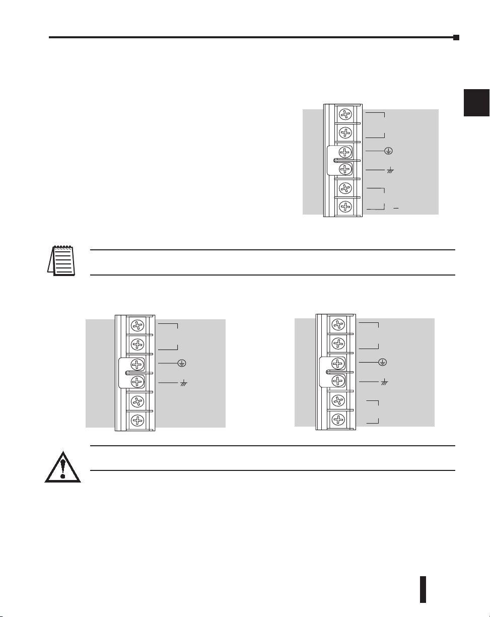
Base Wiring Guidelines
125 VDC Base Terminal Strip12/24 VDC Base Terminal Strip
G
LG
12 – 24 VDC
+
–
115 – 264 VDC
G
24 VDC OUT,
0.3A
–
+
LG
–
+
110/220 VAC Base T erminal Strip
85 – 264 VAC
G
24 VDC OUT,
0.3A
LG
+
Base Wiring
The diagrams show the terminal
connections located on the power supply
of the DL205 bases. The base terminals
can accept up to 16 AWG. You may be
able to use larger wiring depending on
the type of wire used, but 16 AWG is the
recommended size. Do not overtighten
the connector screws; the recommended
torque value is 7.81 ld-in (0.882 N•m).
Chapter 2: Installation, Wiring and Specifications
1
2
3
4
5
6
7
NOTE: You can connect either a 115 VAC or 220 VAC supply to the AC terminals. Special wiring or jumpers
are not required as with some of the other DirectLOGIC. products.
WARNING: Once the power wiring is connected, install the plastic protective cover. When the cover is
removed there is a risk of electrical shock if you accidentally touch the wiring or wiring terminals.
8
9
10
11
12
13
14
A
B
C
D
DL205 User Manual, 4th Edition, Rev. B
2–13
Page 53
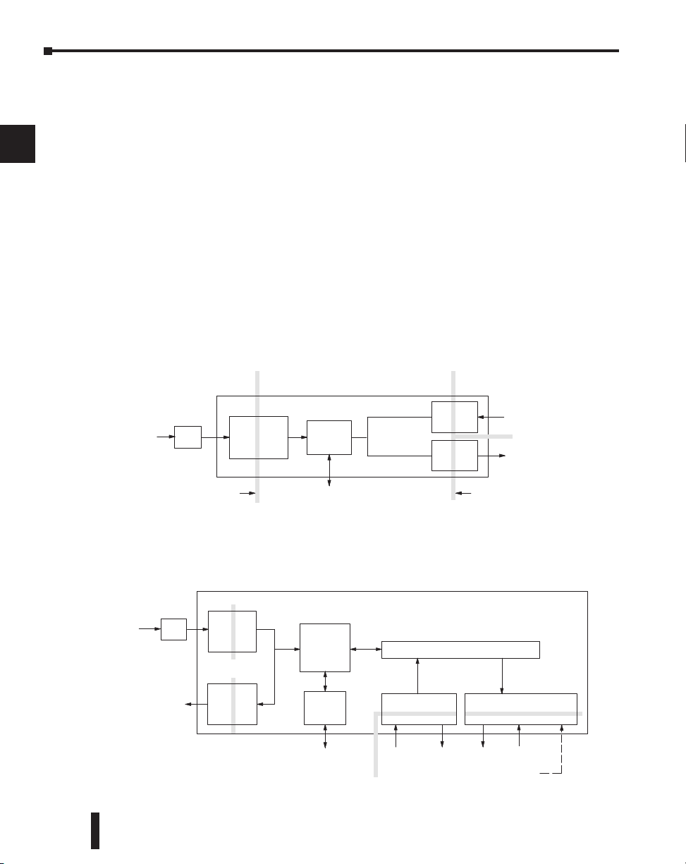
Chapter 2: Installation, Wiring and Specifications
Safety Guidelines
Input Module
CPU
Comm.
Main
Power
Supply
Auxiliary
+24VDC
Supply
To Programming
Device, Operator
Inputs Commons CommonsOutputs
+24VDC Out
PLC
DL205
Interface, Network
Output Module
Internal
Backplane
Supply for
Output Circuit
Primary Side Secondary, or
Logic side
Field Side
Filter
Power
Input
CPU
Input
Module
Main
Power
Supply
Inputs
Outputs
Power
Input
Output
Module
Primary Side Secondary, or
Logic side
Field Side
PLC
Programming Device,
Operator Interface, or Network
Isolation
Boundary
Isolation
Boundary
(backplane)
(backplane)
Filter
I/O Wiring Strategies
1
2
3
4
5
6
7
The DL205 PLC system is very flexible and will work in many different wiring
configurations. By studying this section before actual installation, you can probably find the
best wiring strategy for your application. This will help to lower system cost, wiring errors,
and avoid safety problems.
PLC Isolation Boundaries
PLC circuitry is divided into three main regions separated by isolation boundaries, shown in
the drawing below. Electrical isolation provides safety, so that a fault in one area does not
damage another. A powerline filter will provide isolation between the power source and the
power supply. A transformer in the power supply provides magnetic isolation between the
primary and secondary sides. Opto-couplers provide optical isolation in Input and Output
circuits. This isolates logic circuitry from the field side, where factory machinery connects.
Note the discrete inputs are isolated from the discrete outputs, because each is isolated from
the logic side. Isolation boundaries protect the operator interface (and the operator) from
power input faults or field wiring faults. When wiring a PLC, it is extremely important to
avoid making external connections that connect logic side circuits to any other.
8
9
10
11
12
13
In addition to the basic circuits covered above, AC-powered and 125VDC bases include an
auxiliary +24VDC power supply with its own isolation boundary. Since the supply output is
isolated from the other three circuits, it can power input and/or output circuits!
14
A
B
C
D
2–14
DL205 User Manual, 4th Edition, Rev. B
Page 54
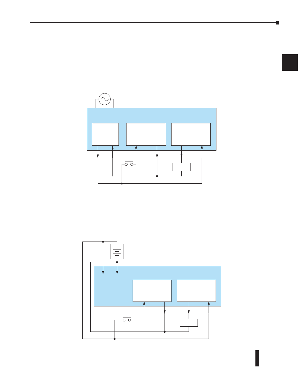
Chapter 2: Installation, Wiring and Specifications
Input Module
Auxiliary
+24VDC
Supply
Power Input
DL205 PLC
Output Module
Loads
AC Power or 125VDC Bases
+
–
Inputs Com. Outputs Com.
Input Module
Power Input
DL205 PLC
Output Module
Loads
DC Power
+
–
+
–
Inputs Com. Outputs Com.
Powering I/O Circuits with the Auxiliary Supply
In some cases, using the built-in auxiliary +24VDC supply can result in a cost savings for
your control system. It can power combined loads up to 300mA. Be careful not to exceed the
current rating of the supply. If you are the system designer for your application, you may be
able to select and design in field devices which can use the +24VDC auxiliary supply.
All AC powered and 125VDC DL205 bases feature the internal auxiliary supply. If input
devices AND output loads need +24VDC power, the auxiliary supply may be able to power
both circuits as shown in the following diagram.
1
2
3
4
5
6
7
8
9
The 12/24VDC powered DL205 bases are designed for application environments in which
low-voltage DC power is more readily available than AC. These include a wide range of
battery–powered applications, such as remotely-located control, in vehicles, portable
machines, etc. For this application type, all input devices and output loads typically use the
same DC power source. Typical wiring for DC-powered applications is shown in the
following diagram.
DL205 User Manual, 4th Edition, Rev. B
10
11
12
13
14
A
B
C
D
2–15
Page 55
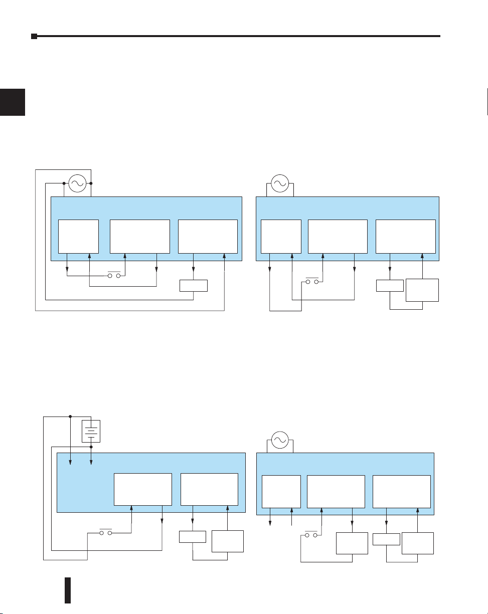
1
Input Module
Auxiliary
+24VDC
Supply
Power Input
DL205 PLC
Output Module
Loads
AC Power
+
–
Inputs Com. Outputs Com.
Input Module
Auxiliary
+24VDC
Supply
Power Input
DL205 PLC
Output Module
Loads
AC Power
+
–
Inputs Com. Outputs Com.
Load
Supply
Input Module
Power Input
DL205 PLC
Output Module
Loads
DC Power
+
–
+
–
Inputs Com. Outputs Com.
Load
Supply
Input Module
Auxiliary
+24VDC
Supply
Power Input
DL205 PLC
Output Module
Loads
AC Power
+
–
Inputs Com. Outputs Com.
Load
Supply
Input
Supply
2
3
4
5
6
7
8
9
Chapter 2: Installation, Wiring and Specifications
Powering I/O Circuits Using Separate Supplies
In most applications it will be necessary to power the input devices from one power source,
and to power output loads from another source. Loads often require high-energy AC power,
while input sensors use low-energy DC. If a machine operator is likely to come in close
contact with input wiring, then safety reasons also require isolation from high-energy output
circuits. It is most convenient if the loads can use the same power source as the PLC, and the
input sensors can use the auxiliary supply, as shown to the left in the figure below.
If the loads cannot be powered from the PLC supply, then a separate supply must be used as
shown to the right in the figure below.
10
11
12
13
14
A
B
C
D
2–16
Some applications will use the PLC external power source to also power the input circuit.
This typically occurs on DC-powered PLCs, as shown in the drawing below to the left. The
inputs share the PLC power source supply, while the outputs have their own separate supply.
A worst-case scenario, from a cost and complexity viewpoint, is an application which requires
separate power sources for the PLC, input devices, and output loads. The example wiring
diagram below on the right shows how this can work, but also the auxiliary supply output is
an unused resource. You will want to avoid this situation if possible.
DL205 User Manual, 4th Edition, Rev. B
Page 56
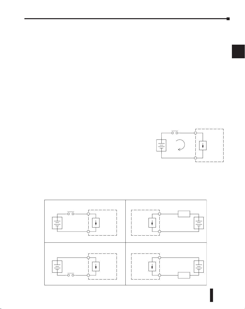
Chapter 2: Installation, Wiring and Specifications
+
–
Input
Sensing
PLC
Input
Common
(sinking)
+
–
Input
Sensing
Load
Sinking Input Sinking Output
Sourcing Input Sourcing Output
PLC
Input
Common
+
–
Output
Switch
PLC
Output
Common
+
–
Input
Sensing
Load
PLC
Input
Common
+
–
Output
Switch
PLC
Output
Common
Sinking / Sourcing Concepts
Before going further in the study of wiring strategies, you must have a solid understanding of
“sinking” and “sourcing” concepts. Use of these terms occurs frequently in input or output
circuit discussions. It is the goal of this section to make these concepts easy to understand,
further ensuring your success in installation. First the following short definitions are provided,
followed by practical applications.
Sinking = provides a path to supply ground (–)
Sourcing = provides a path to supply source (+)
First you will notice these are only associated with DC circuits and not AC, because of the
reference to (+) and (–) polarities. Therefore, sinking and sourcing terminology only applies
to DC input and output circuits. Input and output points that are sinking only or sourcing
only can conduct current in only one direction. This means it is possible to connect the
external supply and field device to the I/O point with current trying to flow in the wrong
direction, and the circuit will not operate. However, you can successfully connect the supply
and field device every time by understanding “sourcing” and “sinking”.
For example, the figure to the right depicts a “sinking”
input. To properly connect the external supply, you
will have to connect it so the input provides a path to
ground (–). Start at the PLC input terminal, follow
through the input sensing circuit, exit at the common
terminal, and connect the supply (–) to the common
terminal. By adding the switch, between the supply (+)
and the input, the circuit has been completed .
Current flows in the direction of the arrow when the
switch is closed.
Apply the circuit principle above to the four possible combinations of input/output
sinking/sourcing types as shown below. The I/O module specifications at the end of this
chapter list the input or output type.
1
2
3
4
5
6
7
8
9
10
11
12
DL205 User Manual, 4th Edition, Rev. B
13
14
A
B
C
D
2–17
Page 57
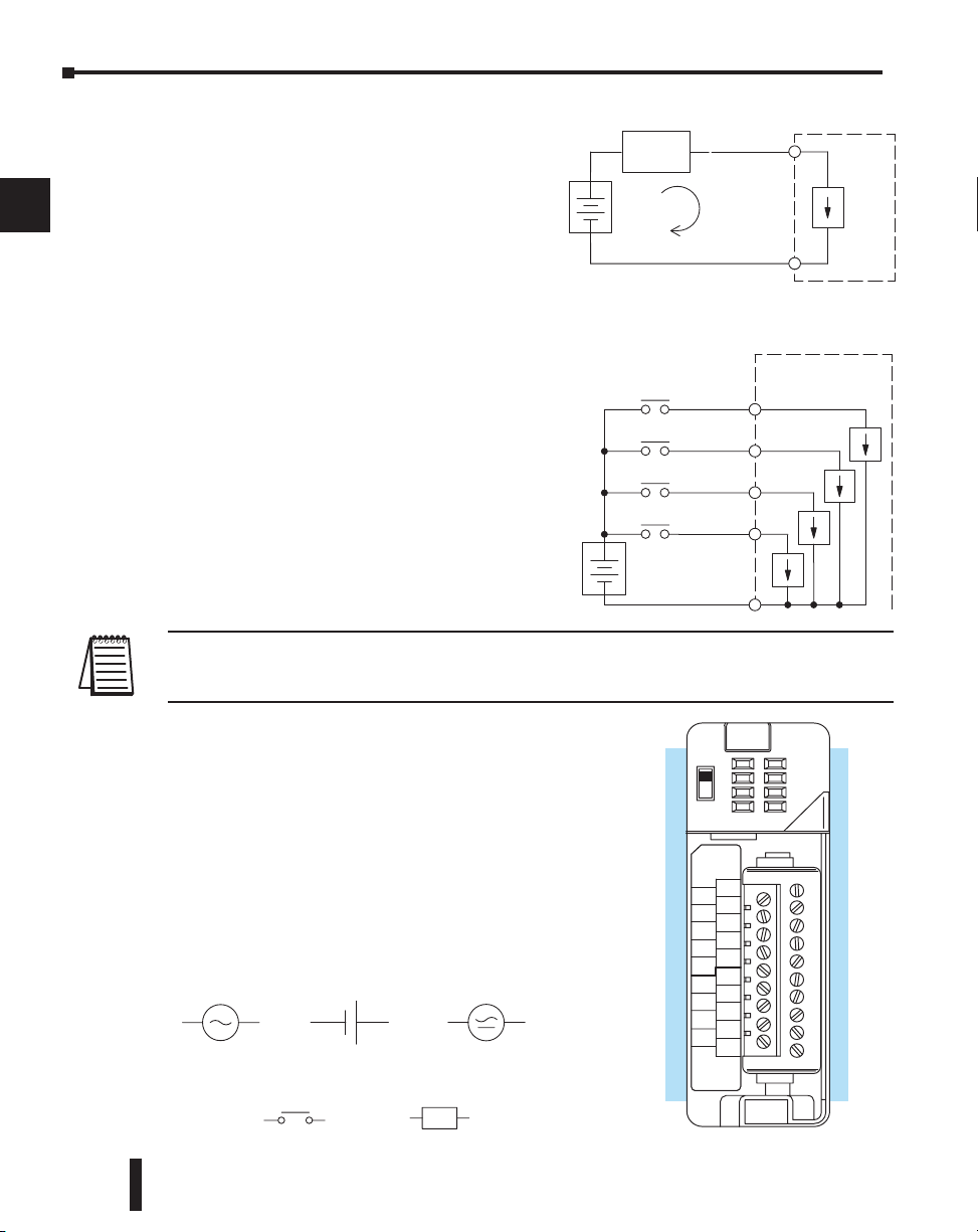
1
L
AC supply AC or DC supply
Input Switch
Output Load
DC supply
+–
+
–
I/O
Circuit
PLC
(I/O Point)
Return Path
Field
Device
Main Path
+
–
Input
Sensing
PLC
Input 4
Common
Input 3
Input 2
Input 1
A
B
20-28VDC
8mA
CLASS 2
D2-16ND3-2
IN 24
D2–16ND3–2
VDC
0
1
2
3
4
5
6
7
CA
4
5
6
7
CB
4
5
6
3
2
1
0
NC
3
2
1
0
7
2
3
4
Chapter 2: Installation, Wiring and Specifications
I/O “Common” Terminal Concepts
In order for a PLC I/O circuit to operate,
current must enter at one terminal and exit
at another. Therefore, at least two terminals
are associated with every I/O point. In the
figure to the right, the Input or Output
terminal is the main path for the current.
One additional terminal must provide the
return path to the power supply.
5
6
7
8
9
10
11
12
13
14
A
B
C
D
2–18
If there was unlimited space and budget for
I/O terminals, every I/O point could have
two dedicated terminals as the figure above
shows. However, providing this level of
flexibility is not practical or even necessary
for most applications. So, most Input or
Output points on PLCs are in groups which
share the return path (called commons). The
figure to the right shows a group (or bank) of
four input points which share a common
return path. In this way, the four inputs
require only five terminals instead of eight.
NOTE: In the circuit above, the current in the common path is 4 times any channel’s input current when all
inputs are energized. This is especially important in output circuits, where heavier gauge wire is
sometimes necessary on commons.
Most DL205 input and output modules group their I/O
points into banks that share a common return path.
The best indication of I/O common grouping is on the
wiring label, such as the one shown to the right. There
are two circuit banks with eight input points in each.
The common terminal for each is labeled “CA” and
“CB”, respectively.
In the wiring label example, the positive terminal of a
DC supply connects to the common terminals. Some
symbols you will see on the wiring labels, and their
meanings are:
DL205 User Manual, 4th Edition, Rev. B
Page 58
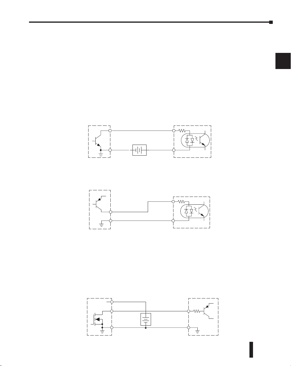
Chapter 2: Installation, Wiring and Specifications
Field Device
+–
PLC DC Input
Output
Ground
Input
Common
Supply
(sinking)
(sourcing)
Field Device
PLC DC Input
Output (sourcing)
Ground
Input
Common
+V
(sinking)
Field Device
Output
Ground
Input
Common
+V
PLC DC Sinking Output
+DC pwr
+
–
(sourcing)
(sinking)
Power
10–30 VDC
Connecting DC I/O to “Solid State” Field Devices
In the previous section on Sourcing and Sinking concepts, the DC I/O circuits were
explained to sometimes only allow current to flow one way. This is also true for many of the
field devices which have solid-state (transistor) interfaces. In other words, field devices can
also be sourcing or sinking. When connecting two devices in a series DC circuit, one must be
wired as sourcing and the other as sinking.
Solid State Input Sensors
Several DL205 DC input modules are flexible because they detect current flow in either
direction, so they can be wired as either sourcing or sinking. In the following circuit, a field
device has an open-collector NPN transistor output. It sinks current from the PLC input
point, which sources current. The power supply can be the +24 auxiliary supply or another
supply (+12 VDC or +24VDC), as long as the input specifications are met.
In the next circuit, a field device has an open-collector PNP transistor output. It sources
current to the PLC input point, which sinks the current back to ground. Since the field
device is sourcing current, no additional power supply is required.
1
2
3
4
5
6
7
8
9
10
Solid State Output Loads
Sometimes an application requires connecting a PLC output point to a solid state input on a
device. This type of connection is usually made to carry a low-level control signal, not to send
DC power to an actuator.
Several of the DL205 DC output modules are the sinking type. This means that each DC
output provides a path to ground when it is energized. In the following circuit, the PLC
output point sinks current to the output common when energized. It is connected to a
sourcing input of a field device input.
DL205 User Manual, 4th Edition, Rev. B
11
12
13
14
A
B
C
D
2–19
Page 59
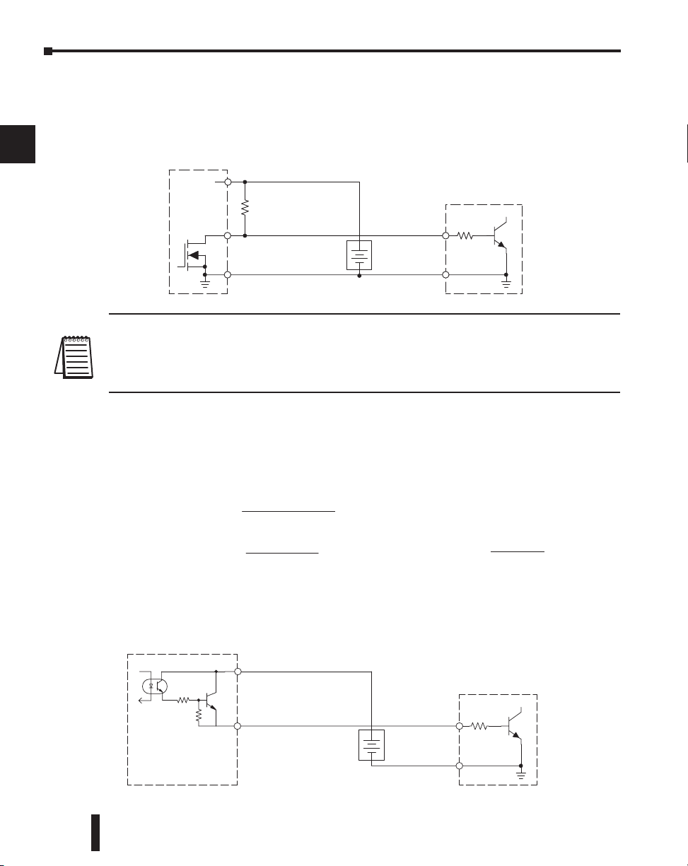
1
Field Device
Output
Ground
Input
Common
PLC DC Sourcing Output
+DC pwr
+
–
(sourcing)
(sinking)
Supply
input
R
Field Device
Output
Ground
Input
Common
PLC DC Output
+DC pwr
+
–
(sourcing)
(sinking)
P
ower
(sinking)
pull-up
Supply
R
input
R
pull-up
R
input
R
=
supply
V
– 0.7
–
input
I
input
I
=
input (turn–on)
V
input
R
pull-up
P
=
supply
V
2
pullup
R
2
3
4
5
6
Chapter 2: Installation, Wiring and Specifications
In the next example a PLC sinking DC output point is connected to the sinking input of a
field device. This is a little tricky, because both the PLC output and field device input are
sinking type. Since the circuit must have one sourcing and one sinking device, a sourcing
capability needs to be added to the PLC output by using a pull-up resistor. In the circuit
below, a R
is connected from the output to the DC output circuit power input.
pull-up
7
8
9
10
11
12
13
14
A
B
C
D
2–20
NOTE 1: DO NOT attempt to drive a heavy load (>25 mA) with this pull-up method
NOTE 2: Using the pull-up resistor to implement a sourcing output has the effect of inverting the output
point logic. In other words, the field device input is energized when the PLC output is OFF, from a ladder
logic point of view. Your ladder program must comprehend this and generate an inverted output. Or, you
may choose to cancel the effect of the inversion elsewhere, such as in the field device.
It is important to choose the correct value of R
the nominal input current to the field device (I
is not known, it can be calculated as shown (a typical value is 15 mA). Then use I
the voltage of the external supply to compute R
watts), in order to size R
Of course, the easiest way to drive a sinking input field device as shown below is to use a DC
sourcing output module. The Darlington NPN stage will have about 1.5 V ON-state
saturation, but this is not a problem with low-current solid-state loads.
DL205 User Manual, 4th Edition, Rev. B
pull-up
properly.
. In order to do so, you need to know
pull-up
) when the input is energized. If this value
input
. Then calculate the power P
pull-up
input
pull-up
and
(in
Page 60
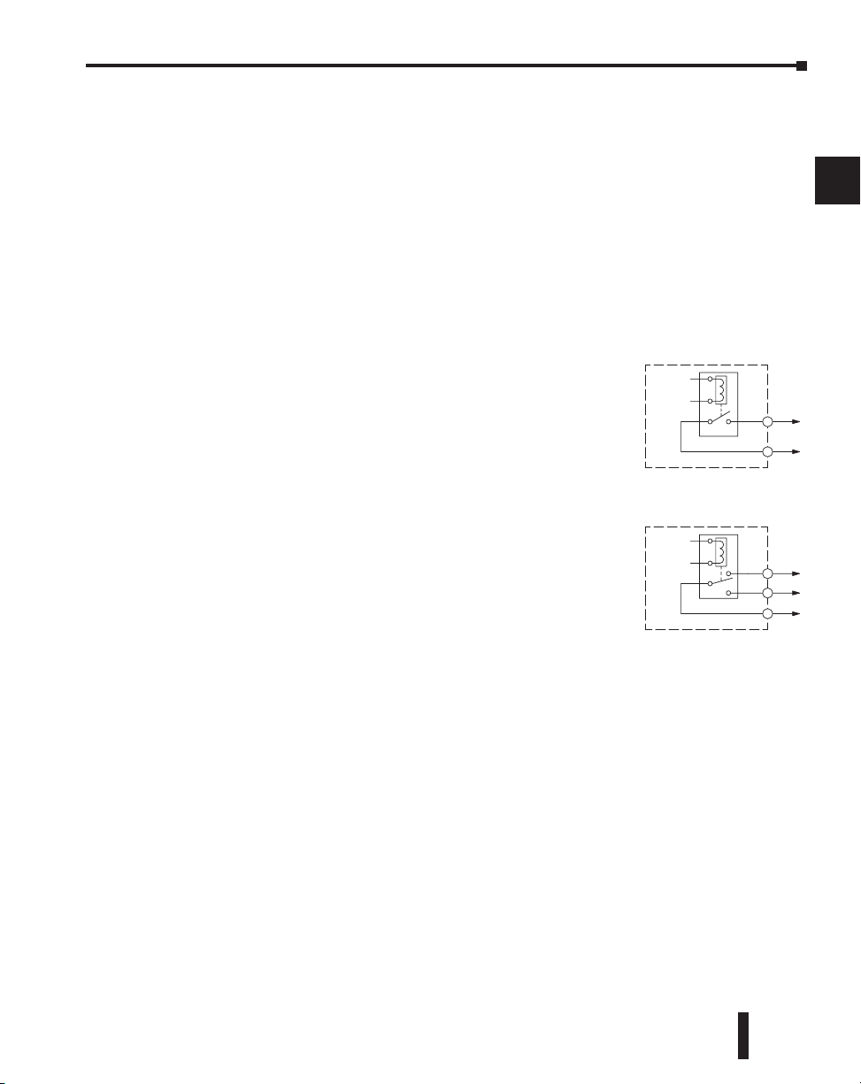
Chapter 2: Installation, Wiring and Specifications
Relay with Form A contacts
Relay with Form C contacts
Relay Output Guidelines
Several output modules in the DL205 I/O family feature relay outputs: D2–04TRS,
D2–08TR, D2–12TR, D2–08CDR, F2–08TR and F2–08TRS. Relays are best for the
following applications:
• Loads that require higher currents than the solid-state outputs can deliver
• Cost-sensitive applications
• Some output channels need isolation from other outputs (such as when some loads require different
voltages than other loads)
Some applications in which NOT to use relays:
• Loads that require currents under 10 mA
• Loads which must be switched at high speed or heavy duty cycle
1
2
3
4
5
Relay Outputs – Transient Suppression for Inductive Loads in a Control System
Relay outputs in the DL205 output modules are available in
two contact arrangements, shown to the right. The Form A
type, or SPST (single pole, single throw) type is normally open
and is the simplest to use. The Form C type, or SPDT (single
pole, double throw) type has a center contact which moves and
a stationary contact on either side. This provides a normally
closed contact and a normally open contact.
Some relay output module’s relays share common terminals,
which connect to the wiper contact in each relay of the bank.
Other relay modules have relays which are completely isolated
from each other. In all cases, the module drives the relay coil
when the corresponding output point is on.
The following pages are intended to give a quick overview of the negative effects of transient
voltages on a control system and provide some simple advice on how to effectively minimize
them. The need for transient suppression is often not apparent to the newcomers in the
automation world. Many mysterious errors that can afflict an installation can be traced back to
a lack of transient suppression.
What is a Transient Voltage and Why is it Bad?
Inductive loads (devices with a coil) generate transient voltages as they transition from being
energized to being de-energized. If not suppressed, the transient can be many times greater than
the voltage applied to the coil. These transient voltages can damage PLC outputs or other
electronic devices connected to the circuit, and cause unreliable operation of other electronics
in the general area. Transients must be managed with suppressors for long component life and
reliable operation of the control system.
This example shows a simple circuit with a small 24V/125mA/3W relay. As you can see, when
the switch is opened, thereby de-energizing the coil, the transient voltage generated across the
switch contacts peaks at 140V.
6
7
8
9
10
11
12
13
14
A
B
C
D
DL205 User Manual, 4th Edition, Rev. B
2–21
Page 61
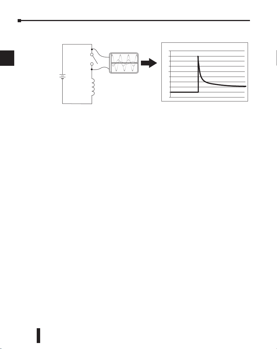
1
Oscilloscope
Relay Coil
(24V/125mA/3W,
AutomationDirect part no.
750-2C-24D)
24 VDC
+
-
160
140
120
100
40
20
-20
Volts
80
60
0
2
3
4
5
6
7
8
9
10
11
12
13
14
A
B
Chapter 2: Installation, Wiring and Specifications
Example: Circuit with no Suppression
In the same circuit, replacing the relay with a larger 24V/290mA/7W relay will generate a
transient voltage exceeding 800V (not shown). Transient voltages like this can cause many
problems, including:
• Relay contacts driving the coil may experience arcing, which can pit the contacts and reduce the
relay's lifespan.
• Solid state (transistor) outputs driving the coil can be damaged if the transient voltage exceeds the
transistor's ratings. In extreme cases, complete failure of the output can occur the very first time a
coil is de-energized.
• Input circuits, which might be connected to monitor the coil or the output driver, can also be
damaged by the transient voltage.
A very destructive side-effect of the arcing across relay contacts is the electromagnetic
interference (EMI) it can cause. This occurs because the arcing causes a current surge, which
releases RF energy. The entire length of wire between the relay contacts, the coil, and the power
source carries the current surge and becomes an antenna that radiates the RF energy. It will
readily couple into parallel wiring and may disrupt the PLC and other electronics in the area.
This EMI can make an otherwise stable control system behave unpredictably at times.
PLC's Integrated Transient Suppressors
Although the PLC's outputs typically have integrated suppressors to protect against transients,
they are not capable of handling them all. It is usually necessary to have some additional
transient suppression for an inductive load.
The next example uses the same 24V/125mA/3W relay used earlier. This example measures the
PNP transistor output of a D0-06DD2 PLC, which incorporates an integrated Zener diode for
transient suppression. Instead of the 140V peak in the first example, the transient voltage here
is limited to about 40V by the Zener diode. While the PLC will probably tolerate repeated
transients in this range for some time, the 40V is still beyond the module's peak output voltage
rating of 30V.
C
D
2–22
DL205 User Manual, 4th Edition, Rev. B
Page 62
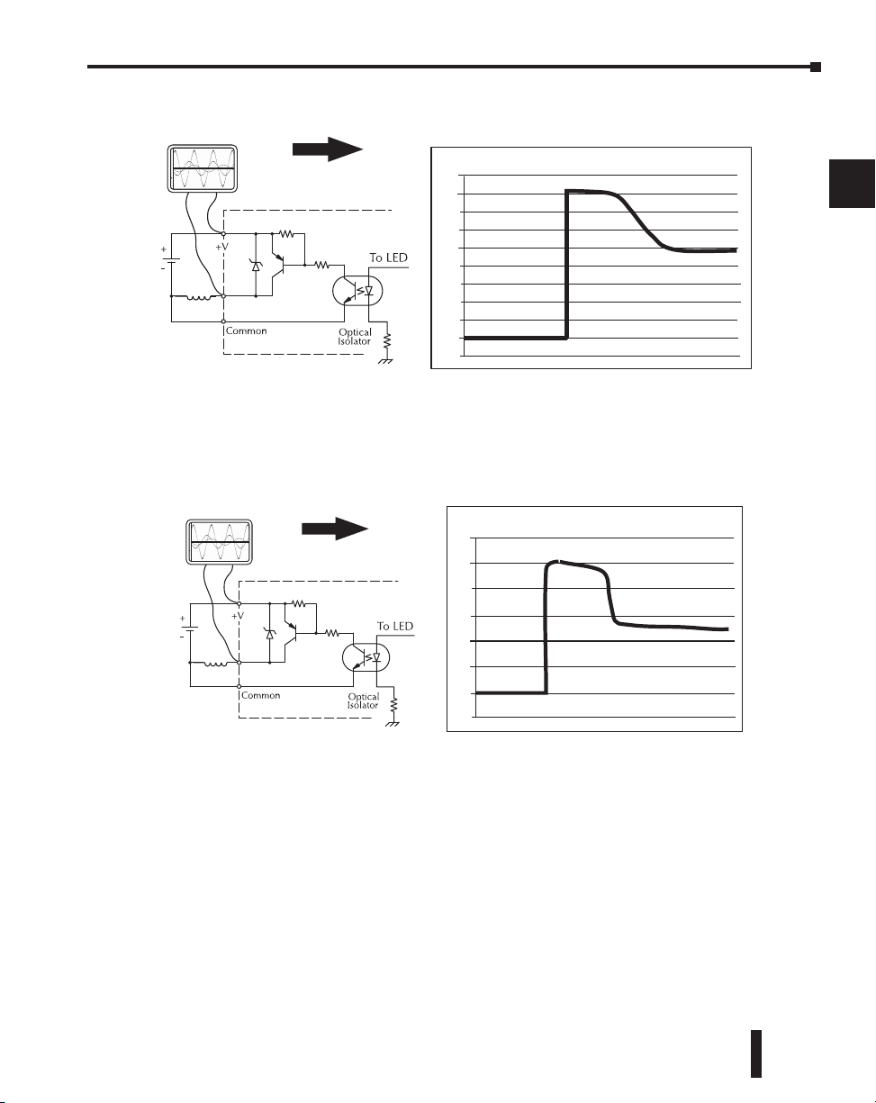
Chapter 2: Installation, Wiring and Specifications
Relay
Coil*
24
VDC
Oscilloscope
* For this example, a 24/290mA/7W
relay is used (AutomationDirect
part no. SC-E03G-24VDC)
60
50
40
30
20
10
0
-10
Volts
Relay
Coil*
24
VDC
Oscilloscope
* For this example, a 24V/125mA/3W
relay is used (AutomationDirect
part no. 750-2C-24D)
45
40
35
30
15
10
0
-5
Volts
25
20
5
Example: Small Inductive Load with Only Integrated Suppression
1
2
3
4
5
The next example uses the same circuit as above, but with a larger 24V/290mA/7W relay,
thereby creating a larger inductive load. As you can see, the transient voltage generated is much
worse, peaking at over 50V. Driving an inductive load of this size without additional transient
suppression is very likely to permanently damage the PLC output.
Example: Larger Inductive Load with Only Integrated Suppression
Additional transient suppression should be used in both these examples. If you are unable to
measure the transients generated by the connected loads of your control system, using
additional transient suppression on all inductive loads would be the safest practice.
DL205 User Manual, 4th Edition, Rev. B
6
7
8
9
10
11
12
13
14
A
B
C
D
2–23
Page 63
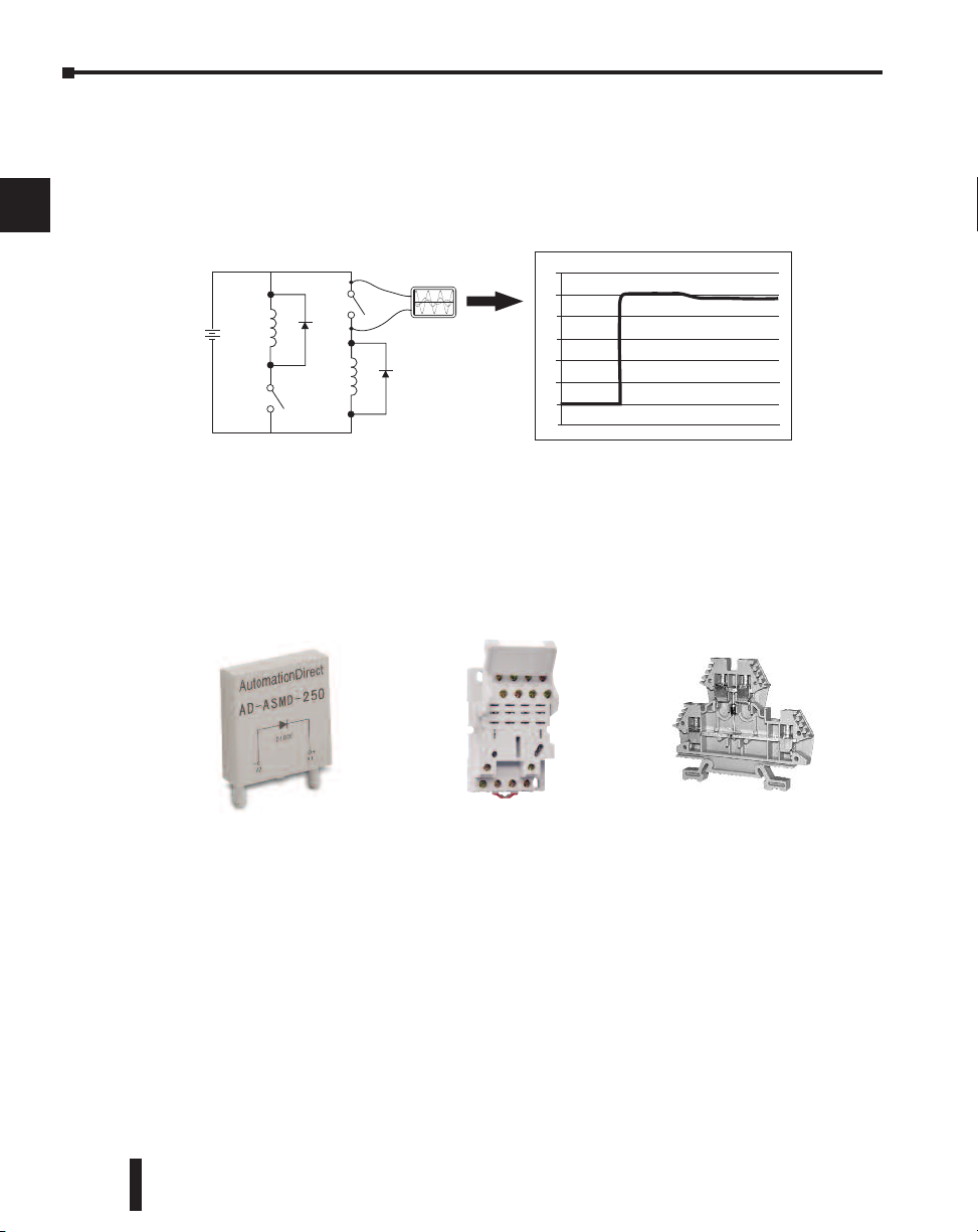
1
Oscilloscope
24 VDC
DC Flyback Circuit
Sinking
Sourcing
+
_
30
25
20
15
10
5
0
-5
Volts
2
3
4
5
6
Chapter 2: Installation, Wiring and Specifications
Types of Additional Transient Protection
DC Coils:
The most effective protection against transients from a DC coil is a flyback diode. A flyback
diode can reduce the transient to roughly 1V over the supply voltage, as shown in this example.
7
8
9
10
11
12
13
14
A
B
C
D
2–24
Many AutomationDirect socketed relays and motor starters have add-on flyback diodes that
plug or screw into the base, such as the AD-ASMD-250 protection diode module and
784-4C-SKT-1 socket module shown below. If an add-on flyback diode is not available for your
inductive load, an easy way to add one is to use AutomationDirect's DN-D10DR-A diode
terminal block, a 600VDC power diode mounted in a slim DIN rail housing.
DL205 User Manual, 4th Edition, Rev. B
AD-ASMD-250
Protection Diode Module
784-4C-SKT-1
Relay Socket
DN-D10DR-A
Diode Terminal Block
Page 64
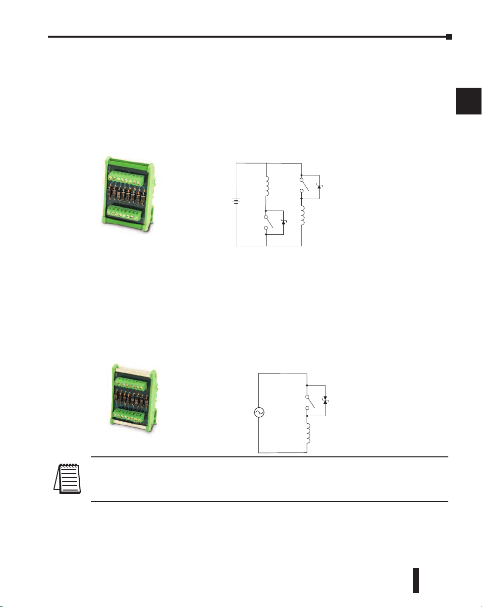
Chapter 2: Installation, Wiring and Specifications
24 VDC
DC MOV or TVS Diode Circuit
Sinking
Sourcing
+
_
VAC
AC MOV or Bi-Directional Diode Circuit
Two more common options for DC coils are Metal Oxide Varistors (MOV) or TVS diodes.
These devices should be connected across the driver (PLC output) for best protection as shown
below. The optimum voltage rating for the suppressor is the lowest rated voltage available that
will NOT conduct at the supply voltage, while allowing a safe margin.
AutomationDirect's ZL-TSD8-24 transorb module is a good choice for 24VDC circuits. It is
a bank of 8 uni-directional 30V TVS diodes. Since they are uni-directional, be sure to observe
the polarity during installation. MOVs or bi-directional TVS diodes would install at the same
location, but have no polarity concerns.
1
2
3
4
5
6
7
AC Coils:
Two options for AC coils are MOVs or bi-directional TVS diodes. These devices are most
effective at protecting the driver from a transient voltage when connected across the driver (PLC
output) but are also commonly connected across the coil. The optimum voltage rating for the
suppressor is the lowest rated voltage available that will NOT conduct at the supply voltage,
while allowing a safe margin.
AutomationDirect's ZL-TSD8-120 transorb module is a good choice for 120VAC circuits. It
is a bank of eight bi-directional 180V TVS diodes.
NOTE: Manufacturers of devices with coils frequently offer MOV or TVS diode suppressors as an add-on
option which mount conveniently across the coil. Before using them, carefully check the suppressor's
ratings. Just because the suppressor is made specifically for that part does not mean it will reduce the
transient voltages to an acceptable level.
For example, a MOV or TVS diode rated for use on 24-48 VDC coils would need to have a
high enough voltage rating to NOT conduct at 48V. That suppressor might typically start
conducting at roughly 60VDC. If it were mounted across a 24V coil, transients of roughly 84V
(if sinking output) or -60V (if sourcing output) could reach the PLC output. Many
semiconductor PLC outputs cannot tolerate such levels.
DL205 User Manual, 4th Edition, Rev. B
8
9
10
11
12
13
14
A
B
C
D
2–25
Page 65
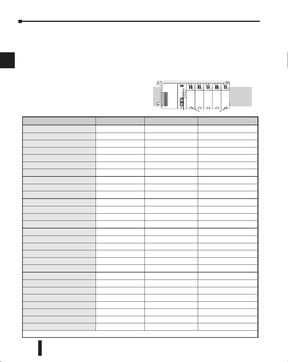
Chapter 2: Installation, Wiring and Specifications
CPU Slot I/O Slots
Slot 0 Slot 1 Slot 2 Slot 3 Slot 4
I/O Modules Position, Wiring, and Specification
1
2
3
4
5
6
7
8
9
10
11
12
13
14
A
B
C
D
Slot Numbering
The DL205 bases each provide different numbers of slots for use with the I/O modules. You
may notice the bases refer to 3-slot, 4-slot, etc. One of the slots is dedicated to the CPU, so
you always have one less I/O slot. For example, you have five I/O slots with a 6-slot base. The
I/O slots are numbered 0 – 4. The CPU slot always contains a PLC CPU or other CPU–slot
controller and is not numbered.
Module Placement Restrictions
The following table lists the valid locations
for all types of modules in a DL205 system:
Module/Unit Local CPU Base Local Expansion Base Remote I/O Base
CPUs
DC Input Modules .
AC Input Modules
DC Output Modules
AC Output Modules
Relay Output Modules
Analog Input and Output Modules
Local Expansion
Base Expansion Module
Base Controller Module
Serial Remote I/O
Remote Master
Remote Slave Unit
Ethernet Remote Master
CPU Interface
Ethernet Base Controller
WinPLC
DeviceNet
Profibus
SDS
Specialty Modules
Counter Interface
Counter I/O
Data Communications
Ethernet Communications
BASIC CoProcessor
Simulator
Filler
* When used with H2-ERM(100) Ethernet Remote I/O system
CPU Slot Only
Slot 0 Only Slot 0 Only*
Slot 0 Only
Slot 0 Only
Slot 0 Only
Slot 0 Only
Slot 0 Only
CPU Slot Only
CPU Slot Only
*
2–26
DL205 User Manual, 4th Edition, Rev. B
Page 66
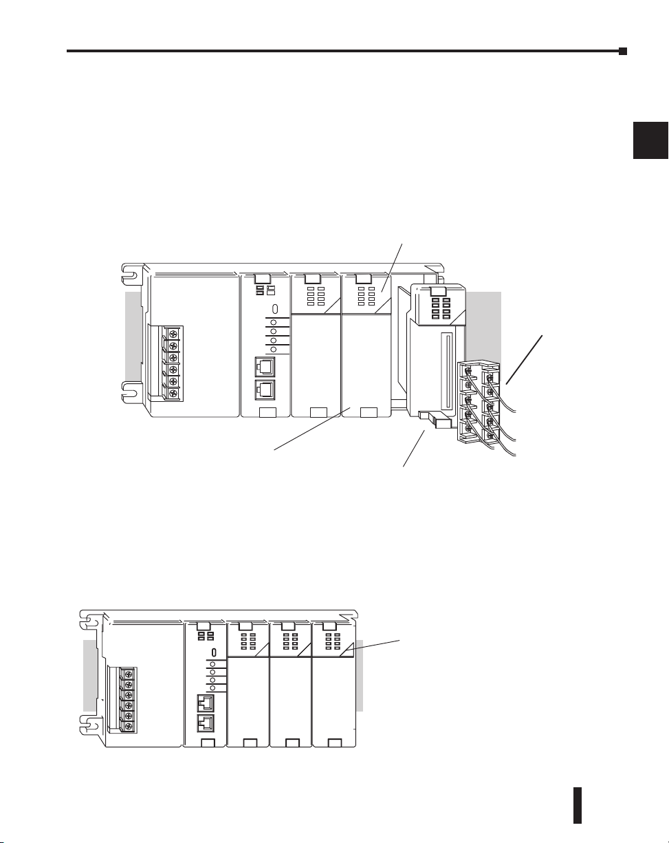
Chapter 2: Installation, Wiring and Specifications
Wire tray area
Status indicators
T
erminal Cover
(installed)
behind terminal cover
T
erminal
Module Type
Discrete/Analog Output
Discrete/Analog Input
Other
Color Code
Red
Blue
White
Color Bar
Special Placement Considerations for Analog Modules
In most cases, the analog modules can be placed in any slot. However, the placement can also
depend on the type of CPU you are using and the other types of modules installed to the left
of the analog modules. If you’re using a DL230 CPU (or a DL240 CPU with firmware earlier
than V1.4) you should check the DL205 Analog I/O Manual for any possible placement
restrictions related to your particular module. You can order the DL205 Analog I/O Manual
by ordering part number D2–ANLG–M.
Discrete Input Module Status Indicators
The discrete modules provide LED status indicators to show the status of the input points.
1
2
3
4
5
6
7
8
9
Color Coding of I/O Modules
The DL205 family of I/O modules have a color coding scheme to help you quickly identify if
a module is either an input module, output module, or a specialty module. This is done
through a color bar indicator located on the front of each module. The color scheme is listed
below:
DL205 User Manual, 4th Edition, Rev. B
10
11
12
13
14
A
B
C
D
2–27
Page 67
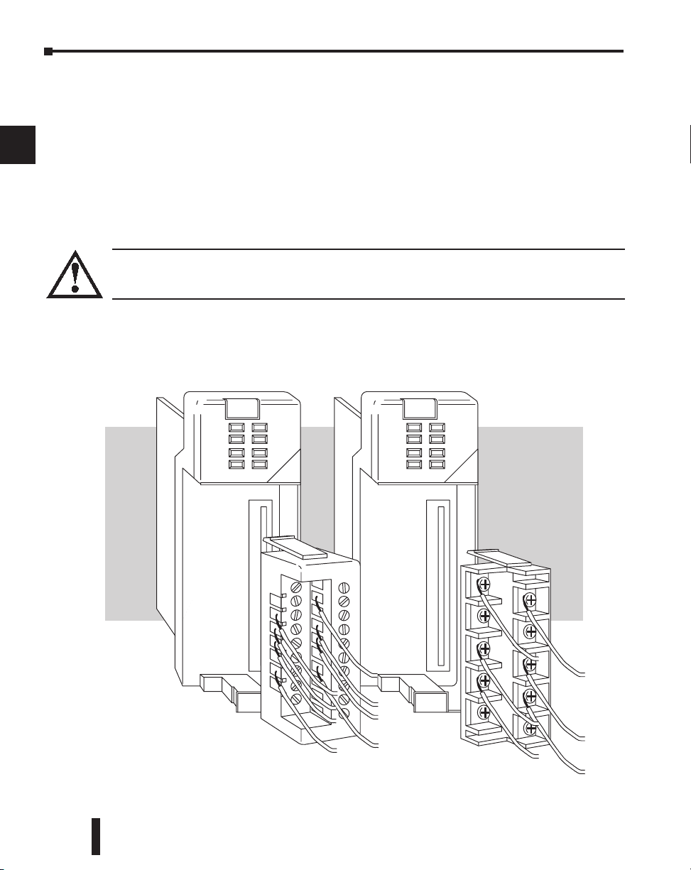
1
2
3
4
5
6
7
8
9
Chapter 2: Installation, Wiring and Specifications
Wiring the Different Module Connectors
There are two types of module connectors for the DL205 I/O. Some modules have normal
screw terminal connectors. Other modules have connectors with recessed screws. The
recessed screws help minimize the risk of someone accidentally touching active wiring.
Both types of connectors can be easily removed. If you examine the connectors closely, you’ll
notice there are squeeze tabs on the top and bottom. To remove the terminal block, press the
squeeze tabs and pull the terminal block away from the module.
We also have DIN rail mounted terminal blocks, DINnectors (refer to our catalog for a
complete listing of all available products). ZIPLinks come with special pre–assembled cables
with the I/O connectors installed and wired.
WARNING: For some modules, field device power may still be present on the terminal block even
though the PLC system is turned off. To minimize the risk of electrical shock, check all field device
power before you remove the connector.
10
11
12
13
14
A
B
C
D
2–28
DL205 User Manual, 4th Edition, Rev. B
Page 68

Chapter 2: Installation, Wiring and Specifications
Safety Guidelines
DINnector External Fuses
(DIN rail mounted Fuses)
I/O Wiring Checklist
Use the following guidelines when wiring the I/O modules in your system.
1. There is a limit to the size of wire the modules can accept. The table below lists the suggested
AWG for each module type. When making terminal connections, follow the suggested torque
values.
Module type Suggested AWG Range Suggested Torque
4 point 16* – 24 AWG 7.81 lb-inch (0.882 N•m)
8 point 16* – 24 AWG 7.81 lb-inch (0.882 N•m)
12 point 16* – 24 AWG 2.65 lb-in (0.3 N•m)
16 point 16* – 24 AWG 2.65 lb-in (0.3 N•m)
1
2
3
4
*NOTE: 16 AWG Type TFFN or Type MTW is recommended. Other types of 16 AWG may be acceptable,
but it really depends on the thickness and stiffness of the wire insulation. If the insulation is too thick or
stiff and a majority of the module’s I/O points are used, then the plastic terminal cover may not close
properly or the connector may pull away from the module. This applies especially for high temperature
thermoplastics such as THHN.
2. Always use a continuous length of wire, do not combine wires to attain a needed length.
3. Use the shortest possible wire length.
4. Use wire trays for routing where possible.
5. Avoid running wires near high energy wiring. Also, avoid running input wiring close to output
wiring where possible.
6. To minimize voltage drops when wires must run a long distance , consider using multiple wires for
the return line.
7. Avoid running DC wiring in close proximity to AC wiring where possible.
8. Avoid creating sharp bends in the wires.
9. To reduce the risk of having a module with a blown fuse, we suggest you add external fuses to your
I/O wiring. A fast blow fuse, with a lower current rating than the I/O module fuse can be added to
each common, or a fuse with a rating of slightly less than the maximum current per output point
can be added to each output. Refer to our catalog for a complete line of DINnectors, DIN rail
mounted fuse blocks.
5
6
7
8
9
10
11
12
13
14
A
NOTE: For modules which have soldered or non-replaceable fuses, we recommend you return your module
to us and let us replace your blown fuse(s) since disassembling the module will void your warranty.
DL205 User Manual, 4th Edition, Rev. B
2–29
B
C
D
Page 69
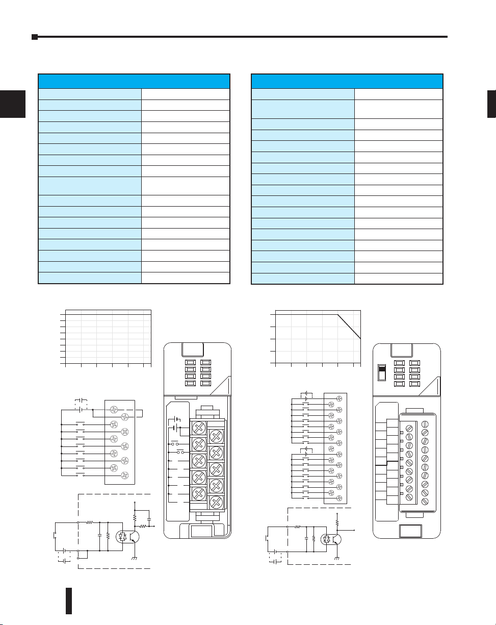
Chapter 2: Installation, Wiring and Specifications
Optica l
COM
Isolator
INP UT
12--24VDC
V+
To LE D
Internal module circuitry
COM
C
C
0
1
2
3
4
5
6
7
12--24VDC
Internally
connected
0
2
4
6
8
0
10 20 30 40 50 55
Ambient Tempera ture (°C/°F )
32
50 68 86 104 122 131C°F°
Derating Chart
Points
+
C
C
0
4
1
5
2
6
3
7
10.2--26.4VDC
4--12mA
D2--08 ND3
IN 12--24
D2--08ND3
VDC
0
1
2
3
4
5
6
7
+
-
-
+
-
+
-
Sink
Source
Sink
Source
A
B
20--28VDC
8mA
IN 24
D2--16ND3 --2
VDC
0
1
2
3
4
5
6
7
CA
4
5
6
7
CB
4
5
6
3
2
1
0
NC
3
2
1
0
7
CLASS2
Optica l
COM
Isolator
Derating Chart
INP UT
24 VDC
V+
To LE D
Internal module circuitry
0
1
2
3
5
6
7
NC
0
1
2
3
CB
4
5
6
7
CA
4
0
4
8
12
16
Points
0 10 20 30 40 50 55
Ambient Tempera ture (°C/°F )
32 50 68 86 104 122 131C°F°
+
+
+
+
-
-
-
+
-
+
-
-
Sink
Source
24 VDC
Sink
Source
Sink
Source
24 VDC
1
2
3
4
5
6
7
8
9
10
D2-08ND3, DC Input
D2-08ND3 DC Input
(sink/source)
Inputs per Module
Commons per Module
Input Voltage Range
Peak Voltage
ON Voltage Level
OFF Voltage Level
AC Frequency
Input Impedance
Input Current
Minimum ON Current
Maximum OFF Current
Base Power Required 5VDC
OFF to ON Response
ON to OFF Response
Terminal Type (included)
Status Indicator
Weight
8
1 (2 I/O terminal points)
0.2-26.4 VDC
1
26.4 VDC
9.5 VDC minimum
3.5 VDC maximum
N/A
2.7 k
4.0 mA @ 12 VDC
8.5 mA @ 24 VDC
3.5 mA
1.5 mA
50 mA
1 to 8 ms
1 to 8 ms
Removable, D2-8IOCON
Logic side
2.3 oz. (65 g)
D2-16ND3-2, DC Input
D2-16ND3-2 DC Input
6 (sink/source)
Inputs per Module
Commons per Module
Input Voltage Range
Peak Voltage
ON Voltage Level
OFF Voltage Level
AC Frequency
Input Impedance
Input Current
Minimum ON Current
Maximum OFF Current
Base Power Required 5VDC
OFF to ON Response
ON to OFF Response
Terminal Type (included)
Status Indicator
Weight
1
isolated (8 I/O terminal
2
points/com)
20-28 VDC
30 VDC (10 mA)
9 VDC minimum
1
7VDC maximum
N/A
3.9 k
6 mA @ 24 VDC
3.5 mA
1.5 mA
100 mA
3 to 9 ms
3 to 9 ms
Removable, D2-16IOCON
Logic side
2.3 oz. (65 g)
11
12
13
14
A
B
C
D
2–30
DL205 User Manual, 4th Edition, Rev. B
Page 70
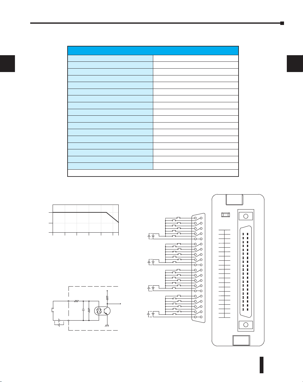
1
Optica l
COM
Isolator
INP UT
24 VDC
V+
ToLogic
Interna l module circuitry
+
IN 24
D2--32ND3
VDC
ACT
22--26VDC
4--6mA
CLASS 2
A0
A1
A2
A3
A4
A5
A6
A7
C0
C1
C2
C3
C4
C5
C6
C7
B0
B1
B2
B3
B4
B5
B7
B6
D0
D1
D2
D3
D4
D5
D6
D7
CI CI
CII
CII
CIII
CIV
CIII
CIV
A4
A
0
A5
A
1
A6
A2
A7
A3
COMI
B4
B0
B5
B1
B6
B2
B7
B3
COMII
C4
C0
C5
C1
C6
C2
C7
C3
COM III
D4
D0
D5
D1
D6
D2
D7
D3
COMIV
0
16
32
Points
0
10 20 30 40 50 55
Ambient Temperature (°C/°F )
32
50 68 86 104 122 131C°F°
Derating Chart
24VDC
+
-
+
-
-
+
-
24VDC
+
-
+
-
+
-
+
-
24VDC
+
-
+
-
24VDC
Sink
Source
Sink
Source
Sink
Source
Sink
Source
Sink
Source
2
3
4
5
6
7
8
9
Chapter 2: Installation, Wiring and Specifications
D2–32ND3, DC Input
D2-32ND3 DC Input
2 (sink/source)
Inputs per Module
Commons per Module
Input Voltage Range
Peak Voltage
ON Voltage Level
OFF Voltage Level
AC Frequency
Input Impedance
Input Current
Minimum ON Current
Maximum OFF Current
Base Power Required 5VDC
OFF to ON Response
ON to OFF Response
Terminal Type (not included)
Status Indicator
Weight
1
Connector sold separately. See Terminal Blocks and Wiring for wiring options.
3
4 isolated (8 I/O terminal points / com)
20-28 VDC
30 VDC
9 VDC minimum
1
7 VDC maximum
N/A
4.8 k
8.0 mA @ 24 VDC
3.5 mA
1.5 mA
25 mA
3 to 9 ms
3 to 9 ms
Removable 40-pin Connector
Module Activity LED
2.1 oz. (60 g)
1
2
3
4
5
6
1
7
8
9
10
11
12
13
14
A
B
C
D
10
11
DL205 User Manual, 4th Edition, Rev. B
12
13
14
A
B
C
D
2–31
Page 71
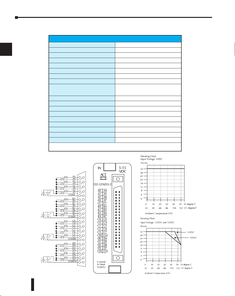
Chapter 2: Installation, Wiring and Specifications
Sink
Source
5-15VDC
Sink
Source
5-15VDC
Sink
Source
5-15VDC
Sink
Source
5-15VDC
D2–32ND3–2, DC Input
1
2
3
4
5
6
7
8
9
10
11
D2-32ND3-2 DC Input
Inputs per Module
Commons per Module
Input Voltage Range
Peak Voltage
ON Voltage Level
OFF Voltage Level
AC Frequency
Input Impedance
Input Current
Maximum Input Current
Minimum ON Current
Maximum OFF Current
Base Power Required 5VDC
OFF to ON Response
ON to OFF Response
Terminal Type (not included)
Status Indicator
Weight
1
Connector sold separately.
See Terminal Blocks and Wiring for wiring options.
32 (Sink/Source)
4
4
16 VDC
4 VDC minimum
2 VDC maximum
N/A
1.0 k @ 5-15 VDC
4 mA @ 5 VDC
11 mA @ 12 VDC
14 mA @ 15 VDC
16 mA @ 15.6 VDC
3 mA
0.5 mA
25 mA
3 to 9 ms
3 to 9 ms
Removable 40-pin connector
Module activity LED
2.1 oz (60 g)
isolated (8 I/O terminal points / com)
.50 to 15.6 VDC min. to max.
1
12
13
14
A
B
C
D
2–32
DL205 User Manual, 4th Edition, Rev. B
Page 72

Chapter 2: Installation, Wiring and Specifications
Optica l
COM
Isolator
INP UT
110 VAC
V+
To LE D
Internal module circuitry
COM
C
C
0
1
2
3
4
5
6
7
Internally
connected
110 VA C
0
2
4
6
8
0
10 20 30 40 50 55
Ambient Tempe rature (˚C/˚F )
32
50 68 86 104 122 131
C˚
F˚
Points
C
C
0
4
1
5
2
6
3
7
80-132VAC
10-20mA
D2--08 NA-1
IN 110
D 2 -- 0 8 N A -- 1
VAC
0
1
2
3
4
5
6
7
50/60Hz
Line
Derating C hart
D2-08NA-1, AC Input
Inputs per Module
Commons per Module
Input Voltage Range
Peak Voltage
ON Voltage Level
OFF Voltage Level
AC Frequency
Input Impedance
Input Current
Minimum ON Current
Maximum OFF Current
Base Power Required 5VDC
OFF to ON Response
ON to OFF Response
Terminal Type (included)
Status Indicator
Weight
D2-08NA-1 AC Input
8
(2 I/O terminal points)
1
80-132 VAC
132 VAC
5 VAC minimum
7
20 VAC maximum
47-63 Hz
12 k @ 60 Hz
13 mA @ 100 VAC, 60 Hz
11 mA @ 100 VAC, 50 Hz
5 mA
2 mA
50 mA
5 to 30 ms
10 to 50 ms
Removable; D2-8IOCON
Logic side
2.5 oz. (70 g)
DL205 User Manual, 4th Edition, Rev. B
1
2
3
4
5
6
7
8
9
10
11
12
13
14
A
B
C
D
2–33
Page 73

Chapter 2: Installation, Wiring and Specifications
Optica l
COM
Isolator
INP UT
220VAC
V+
To LE D
Interna l module circuitry
COM
C
C
0
1
2
3
4
5
6
7
Internally
connected
220VAC
0
2
4
6
8
0
10 20 30 40 50 55
Ambient Tempe rature ( ˚C/˚F)
32
50 68 86 104 122 131
C˚
F˚
Points
Derating Chart
D2-08NA-2, AC Input
1
2
3
4
5
6
7
8
9
10
11
D2-08NA-2 AC Input
Inputs per Module
Commons per Module
Input Voltage Range
Peak Voltage
ON Voltage Level
OFF Voltage Level
AC Frequency
Input Impedance
Input Current
Minimum ON Current
Maximum OFF Current
Base Power Required 5VDC
OFF to ON Response
ON to OFF Response
Terminal Type (included)
Status Indicator
Weight
8
1 (2 I/O terminal points)
170-265 VAC
265 VAC
150 VAC minimum
40 VAC maximum
47-63 Hz
18 k @ 60 Hz
9 mA @ 220 VAC, 50 Hz
11 mA @ 265 VAC, 50 Hz
10 mA @ 220 VAC, 60 Hz
12 mA @ 265 VAC, 60 Hz
10 mA
2 mA
100 mA
5 to 30 ms
10 to 50 ms
Removable; D2-8IOCON
Logic side
2.5 oz. (70 g)
Operating Temperature
Storage Temperature
Humidity
Atmosphere
Vibration
Shock
Insulation Withstand Voltage
Insulation Resistance
Noise Immunity
RFI
2ºF to 131ºF (0º to 55ºC)
3
-4ºF to 158ºF (-20ºC to 70ºC)
5% to 95% (non-condensing)
3
o corrosive gases permitted
N
IL STD 810C 514.2
M
MIL STD 810C 516.2
1,500 VAC 1 minute (COM-GND)
10M @ 500 VDC
NEMA 1,500V 1 minute
SANKI 1,000V 1 minute
150 MHz, 430 MHz
12
13
14
A
B
C
D
2–34
DL205 User Manual, 4th Edition, Rev. B
Page 74
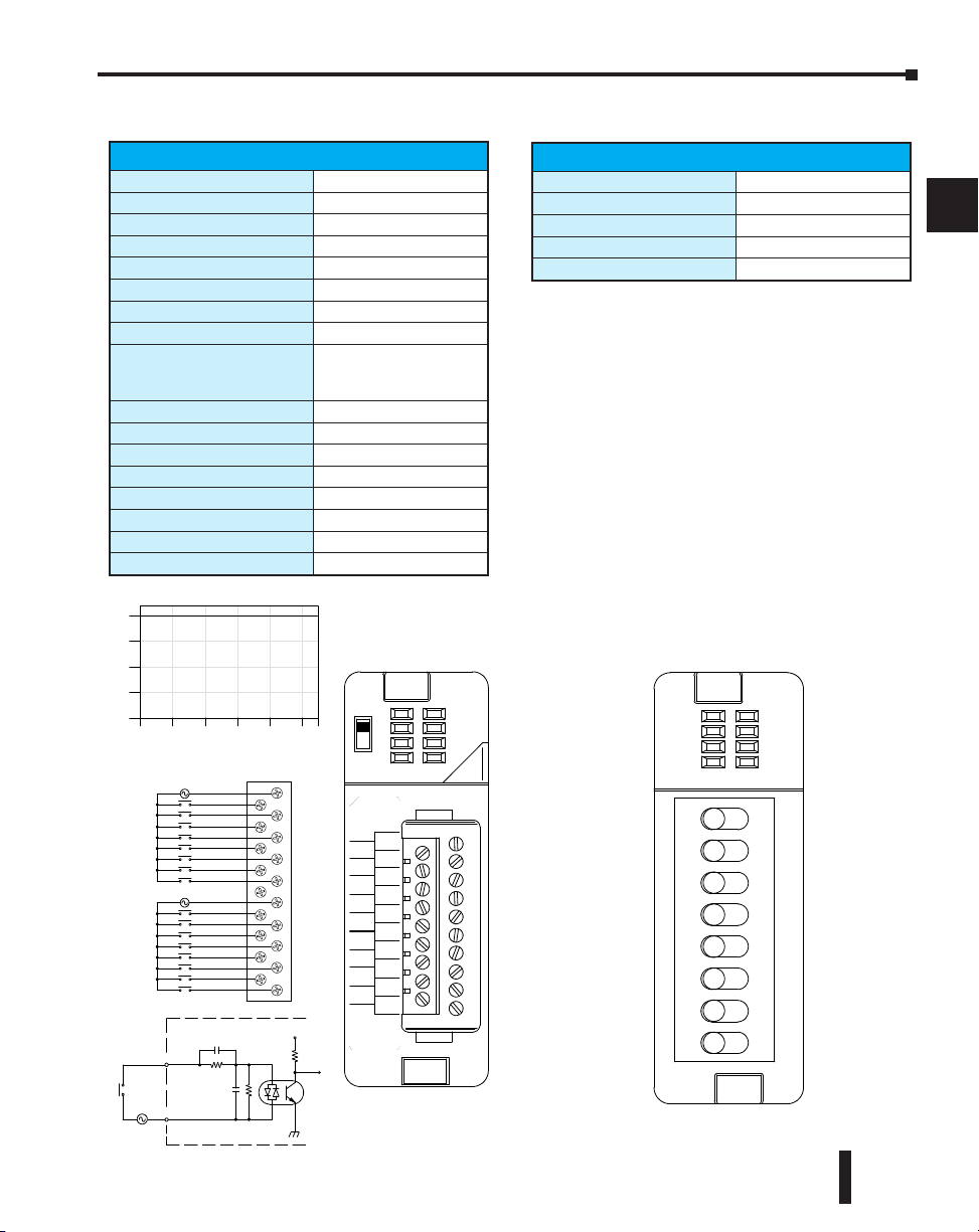
Chapter 2: Installation, Wiring and Specifications
A
B
0 10 20 30 40 50 55
Ambient Tempe rature ( ˚C/˚F )
32 50 68 86 104 122 131
C˚
F˚
Optica l
Isolator
INP UT
110 VAC
V+
To LE D
Internal module c ircuitry
COM
0
1
2
3
5
6
7
NC
0
1
2
3
CB
4
5
6
7
CA
4
0
4
8
12
16
Points
110 VAC
110 VAC
80--132VAC
10--20mA
D2--16 NA
IN 11 0
D2--16NA
VAC
0
1
2
3
4
5
6
7
CA
4
5
6
7
CB
4
5
6
3
2
1
0
NC
3
2
1
0
7
50/60Hz
Derating C hart
IN S IM
F2--08SIM
0
1
2
3
4
5
6
7
ON
>
0
1
2
3
4
5
6
7
D2-16NA, AC Input
Inputs per Module
Commons per Module
Input Voltage Range
Peak Voltage
ON Voltage Level
OFF Voltage Level
AC Frequency
Input Impedance
Input Current
Minimum ON Current
Maximum OFF Current
Base Power Required 5VDC
OFF to ON Response
ON to OFF Response
Terminal Type (included)
Status Indicator
Weight
D2-16NA AC Input
16
(isolated)
2
80-132 VAC
32 VAC
1
70 VAC minimum
20 VAC maximum
47-63 Hz
12 k @ 60 Hz
11 mA @ 100 VAC, 50 Hz
13 mA @ 100 VAC, 60 Hz
15 mA @ 132 VAC, 60 Hz
5 mA
2 mA
100 mA
5 to 30 ms
10 to 50 ms
Removable; D2-16IOCON
Logic side
2.4 oz. (68g)
F2-08SIM, Input Simulator
F2-08SIM Input Simulator
Inputs per Module
Base Power Required 5VDC
Terminal Type
Status Indicator
Weight
8
50 mA
None
Switch side
2.65 oz. (75 g)
1
2
3
4
5
6
7
8
9
10
11
12
13
14
A
B
C
D
DL205 User Manual, 4th Edition, Rev. B
2–35
Page 75
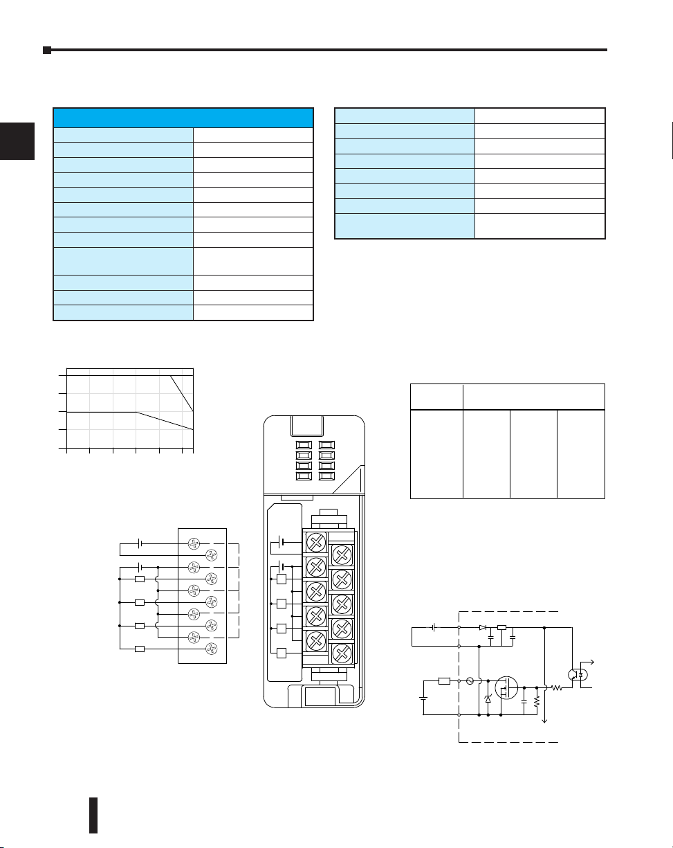
Chapter 2: Installation, Wiring and Specifications
0
1
2
3
4
0
10 20 30 40 50 55
Ambient Tempe rature ( ˚C/˚F)
32 50 68 86 104 122 131
C˚
F˚
Points
2A/Pt.
3A/Pt.
4A/Pt.
0V
24V
C
C
C
C
0
1
2
3
24VDC
Internally
connected
L
L
L
L
+
12- -24VDC
+
C
+24V
0
C
1
C
2
C
3
10.2--26.4VDC
50mA--4A
D2--04 TD1
OU T 12--24
D2--04T D1
VDC
0
1
2
3
L
L
L
L
C
Common
L
12- -24
+
--
+--
24VDC
VDC
To LE D
Optica l
Isolator
0V
Output
Othe r
Circuits
Reg
Inductive Load
0.1A 1400 600
0.5A 300 120
1.0A 140 60
1.5A 90 35
2.0A 70 --
Load
8000
1600
100ms
800
540
3.0A
400
270 -- --
40ms7msCurrent
Duration of output in ON state
4.0A 200
-- --
Maximum Number of Switching Cycles pe r Minute
6.3A
Derating C hart
D2-04TD1, DC Output
1
2
3
4
5
6
Outputs per Module
Output Points Consumed
Commons per Module
Output Type
Operating Voltage
Peak Voltage
ON Voltage Drop
AC Frequency
Max Load Current
(resistive)
Max Leakage Current
Max Inrush Current
Minimum Load Current
7
8
9
10
11
12
13
14
A
B
C
D
2–36
D2-04TD1 DC Output
4 (current sinking)
8 points (only first 4 pts. used)
1 (4 I/O terminal points)
NMOS FET (open drain)
10.2-26.4 VDC
40 VDC
0.72 VDC maximum
N/A
4A/point
8A/common
0.1 mA @ 40 VDC
6A for 100 ms, 15A for 10 ms
50 mA
DL205 User Manual, 4th Edition, Rev. B
External DC Required
Base Power Required 5VDC
OFF to ON Response
ON to OFF Response
Terminal Type (included)
Status Indicator
Weight
Fuses
At 40 mS duration, loads of 3.0A or greater cannot be used.
At 100 mS duration, loads of 2.0A or greater cannot be used.
Find the load current you expect to use and the duration that the
output is ON. The number at the intersection of the row and column
represents the switching cycles per minute. For example, a 1A
inductive load that is on for 100 ms can be switched on and off a
maximum of 60 times per minute. To convert this to duty cycle
percentage use: (duration x cycles)/60. In this example,
(60 x .1)/60 = .1, or 10% duty cycle.
24 VDC @ 20 mA max.
60 mA
1 ms
1 ms
Removable; D2-8IOCON
Logic side
2.8 oz. (80 g)
4 (1 per point)
(6.3 A slow blow, non-replaceable)
Page 76
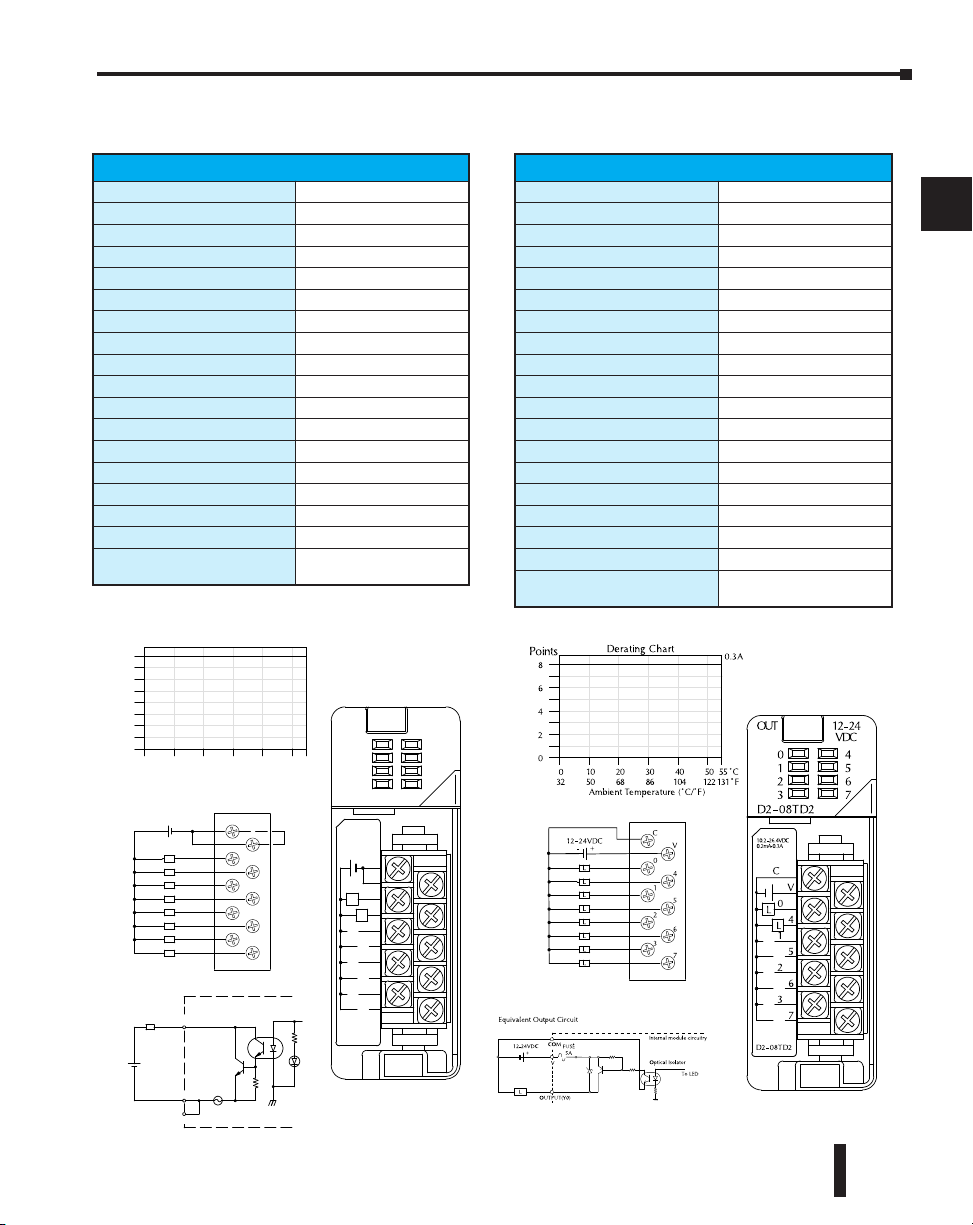
Chapter 2: Installation, Wiring and Specifications
Optica l
Isolator
L
COM
COM
OUTP UT
12--24VDC
+
5A
Internal module circuitry
C
C
0
1
2
3
4
5
6
7
12--24VDC Internally
connected
L
L
L
L
L
L
L
L
0
2
4
6
8
0
10 20 30 40 50 55
Ambient Tempera ture (˚C/˚F)
32 50 68 86 104 122 131
C˚
F˚
Points
+
C
C
0
4
1
5
2
6
3
7
10.2--26.4VDC
0.2mA-0.3A
D2--08T D1
OUT 12 -- 24
D2-- 08TD1
VDC
0
1
2
3
4
5
6
7
L
L
Derating Chart
D2–08TD1, DC Output
D2-08TD1 DC Output
Outputs per Module
Commons per Module
Output Type
Operating Voltage
Peak Voltage
ON Voltage Drop
AC Frequency
Minimum Load Current
Max Load Current
Max Leakage Current
Max Inrush Current
Base Power Required 5VDC
OFF to ON Response
ON to OFF Response
Terminal Type (included)
Status Indicator
Weight
Fuses
8 (current sinking)
1 (2 I/O terminal points)
NPN open collector
10.2-26.4 VDC
40 VDC
1.5 VDC maximum
N/A
0.5 mA
0.3A/point; 2.4A/common
0.1 mA @ 40 VDC
1A for 10 ms
100 mA
1 ms
1 ms
Removable; D2-8IOCON
Logic side
2.3 oz. (65g)
1 per common
5A fast blow, non-replaceable
D2–08TD2, DC Output
D2-08TD2 DC Output
Outputs per Module
Commons per Module
Output Type
Operating Voltage
Output Voltage
Peak Voltage
ON Voltage Drop
AC Frequency
Minimum Load Current
Max Load Current
Max Leakage Current
Max Inrush Current
Base Power Required 5VDC
OFF to ON Response
ON to OFF Response
Terminal Type (included)
Status Indicator
Weight
Fuses
8 (current sourcing)
1
PNP open collector
12 to 24 VDC
10.8 to 26.4 VDC
40 VDC
1.5 VDC
N/A
N/A
0.3A per point; 2.4A per common
1.0 mA @ 40 VDC
1A for 10 ms
100 mA
1 ms
1 ms
Removable; D2-8IOCON
Logic side
2.1 oz. (60g)
1 per common
5A fast blow, non-replaceable
1
2
3
4
5
6
7
8
9
10
11
DL205 User Manual, 4th Edition, Rev. B
12
13
14
A
B
C
D
2–37
Page 77
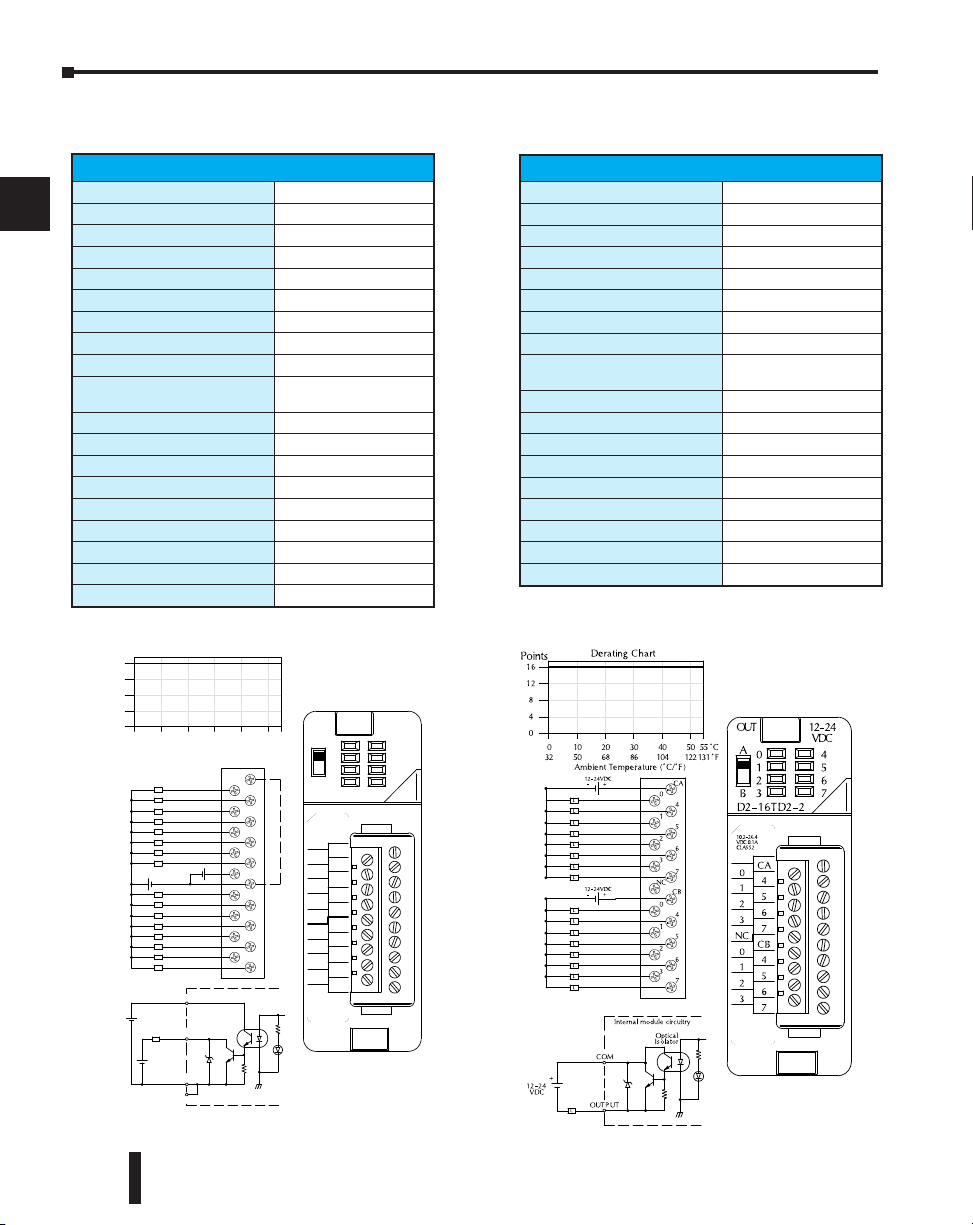
Chapter 2: Installation, Wiring and Specifications
Optica l
Isolator
COM
OUTP UT
12--24
+
Internal module circuitry
L
+V
+
24VDC
0 10 20 30 40 50 55
Ambient Tempera ture (˚C/˚F)
32 50 68 86 104 122 131
C˚
F˚
0
4
8
12
16
Points
0
1
2
3
5
6
7
+V
0
1
2
3
C
4
5
6
7
C
4
L
L
L
L
L
L
L
L
L
L
L
L
L
L
L
L
COM
Internally
connected
12--24VDC
24VDC
A
B
10.2--26.4
VDC0. 1A
OU T 12--24
D2--16T D1 --2
VDC
0
1
2
3
4
5
6
7
C
4
5
6
7
C
4
5
6
3
2
1
0
+V
3
2
1
0
7
CLASS2
A
B
+
+
VDC
* Ca n also be u sed wit h 5VDC su pply
DeratingChart
D2–16TD1–2, DC Output
1
Outputs per Module
2
Commons per Module
Output Type
External DC required
3
Operating Voltage
Peak Voltage
4
ON Voltage Drop
AC Frequency
Minimum Load Current
5
Max Load Current
Max Leakage Current
6
Max Inrush Current
Base Power Required 5VDC
7
OFF to ON Response
ON to OFF Response
Terminal Type (included)
8
Status Indicator
Weight
9
Fuses
D2-16TD1-2 DC Output
10
11
16 (current sinking)
(2 I/O terminal points)
1
NPN open collector
24 VDC ±4V @ 80 mA max
10.2-26.4 VDC
30 VDC
0.5 VDC maximum
N/A
0.2 mA
0.1A/point
1.6A/common
0.1 mA @ 30 VDC
150 mA for 10 ms
200 mA
0.5 ms
0.5 ms
Removable; D2-16IOCON
Logic side
2.3 oz. (65g)
None
D2–16TD2–2, DC Output
D2-16TD2-2 DC Output
Outputs per Module
Commons per Module
Output Type
Operating Voltage
Peak Voltage
ON Voltage Drop
AC Frequency
Minimum Load Current
Max Load Current
Max Leakage Current
Max Inrush Current
Base Power Required 5VDC
OFF to ON Response
ON to OFF Response
Terminal Type (included)
Status Indicator
Weight
Fuses
16 (current sourcing)
2
NPN open collector
10.2-26.4 VDC
30 VDC
1.0 VDC maximum
N/A
0.2 mA
0.1A/point
1.6A/module
0.1 mA @ 30 VDC
150 mA for 10 ms
200 mA
0.5 ms
0.5 ms
Removable; D2-16IOCON
Logic side
2.8 oz. (80g)
None
12
13
14
A
B
C
D
2–38
DL205 User Manual, 4th Edition, Rev. B
Page 78
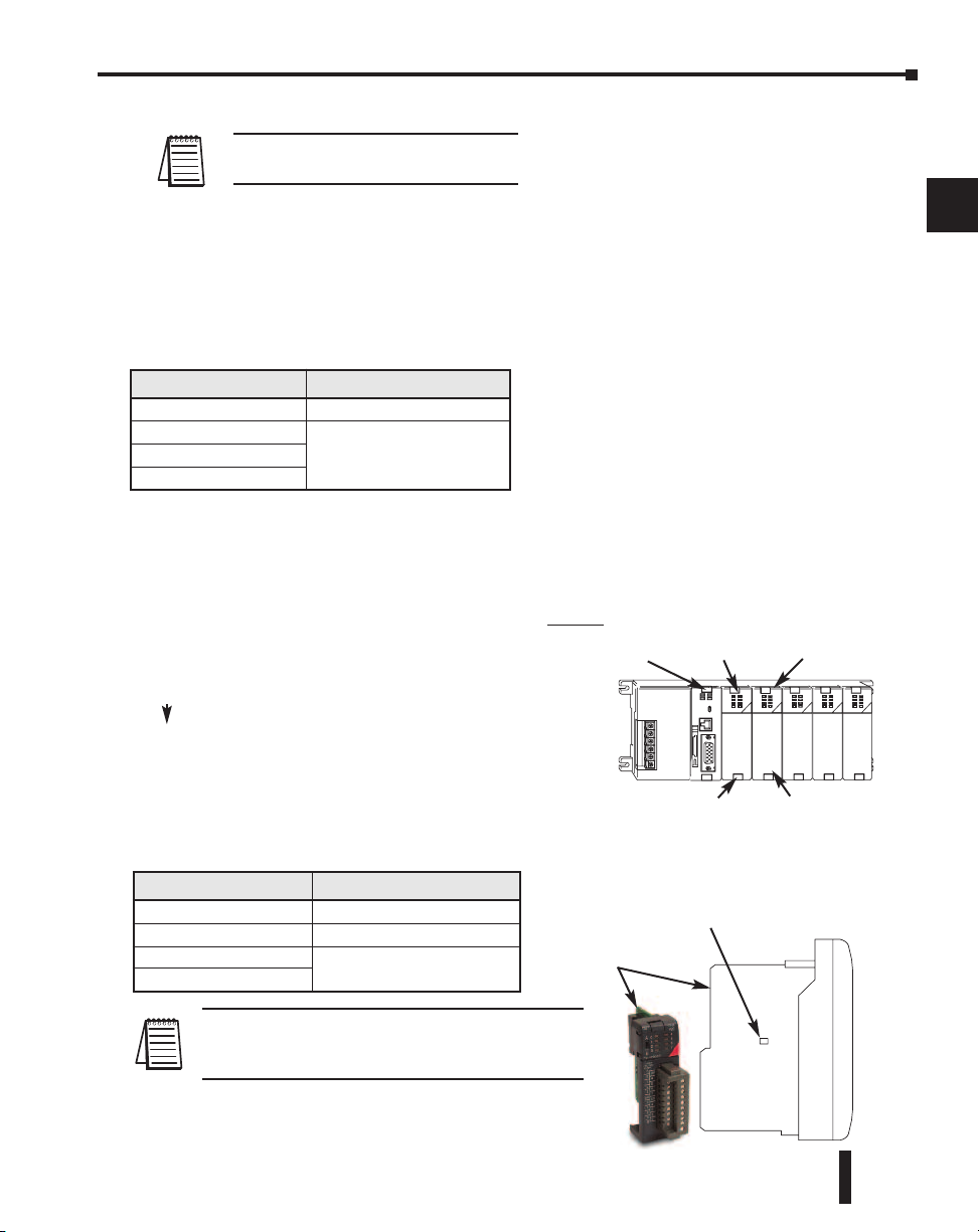
Chapter 2: Installation, Wiring and Specifications
Slot 0 Slot 1 Slot 2 Slot 3 Slot 4
F2–16TD1(2)P, DC Output With Fault Protection
NOTE: Not supported in D2-230, D2-240
and D2-250 CPUs.
These modules detect the following fault status and
turn the related X bit(s) on.
1. Missing external 24VDC for the module
2. Open load
3. Over temperature (the output is shut down)
4. Over load current (the output is shut down)
Fault Status X bit Fault Status Indication
Missing external 24VDC All 16 X bits are on.
Open load
Over temperature
Over load current
When these modules are installed, 16 X
bits are automatically assigned as the
fault status indicator. Each X bit
indicates the fault status of each output.
In this example, X10-X27 are assigned as the fault
status indicator.
X10: Fault status indicator for Y0
X11: Fault status indicator for Y1
1
1
Only the X bit assigned to the
faulted output is on
Example
D2-250-1 or D2-260
D2-08ND3
F2-16TD1P
or
F2-16TD2P
1
2
3
4
5
6
7
8
9
10
11
X26: Fault status indicator for Y16
X27: Fault status indicator for Y17
The fault status indicators (X bits) can be reset by
performing the indicated operations in the
following table:
Fault Status Operation
Missing external 24VDC Apply external 24VDC
Open load
Over temperature
Over load current
1
NOTE 1: Open load detection can be disabled by
removing the jumper switch J6 on the module PC
board.
Connect the load.
Turn the output (Y bit) off or
power cycle the PLC
Continued on next two pages.
X0 - X7
Jumper Switch J6
PC Board
DL205 User Manual, 4th Edition, Rev. B
X10 - X27
Y0 - Y17
12
13
14
A
B
C
D
2–39
Page 79
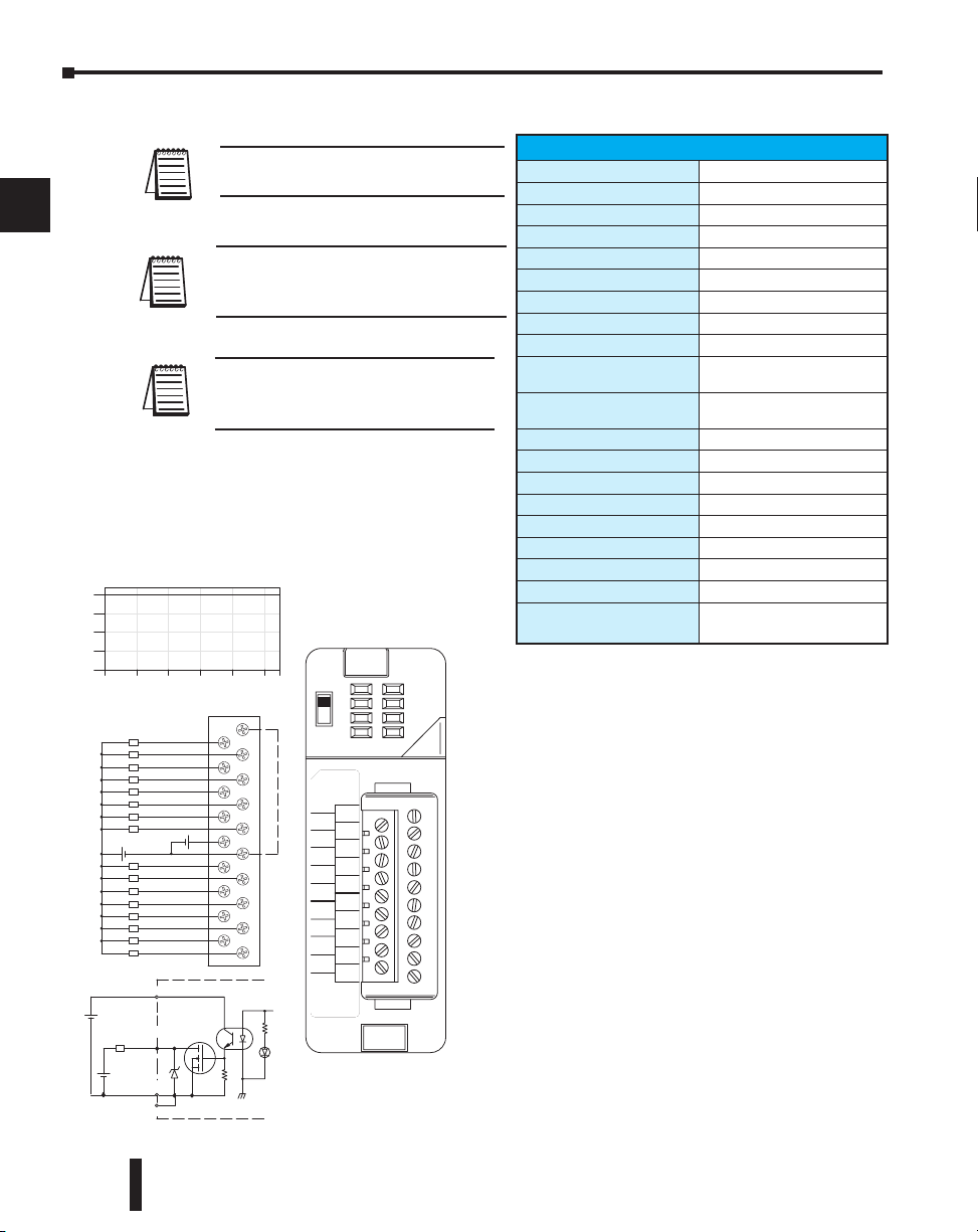
Chapter 2: Installation, Wiring and Specifications
Derating Chart
24VDC
Ambient Temperature (°C/°F)
0
4
8
12
16
Points
0
1
2
3
5
6
7
24V
0
1
2
3
0V
4
5
6
7
4
L
L
L
L
L
L
L
L
L
L
L
L
L
L
L
L
Internally
connected
12–24VDC
A
B
10.2-26.4
VDC 0.25A
CLASS2
OUT 12-24
F2–16TD1P
VDC
0
1
2
3
4
5
6
7
0V
4
5
6
7
0V
4
5
6
3
2
1
0
24V
3
2
1
0
7
A
B
+
+
When the A/B switch is in the A position,
the LEDs display the output status of the
module’s first 8 output points. Positon B
displays the output status of the module’s second group of 8 output points.
0
10 20 30 40 50 55°C
131°F
32 50 68 86 104 122
0V
Optical
Isolator
0V
OUTPUT
12–24
+
Internal module circuitry
L
24V
+
24VDC
VDC
0V
F2–16TD1P, DC Output With Fault Protection
1
2
3
4
5
6
7
8
9
10
11
12
13
14
A
B
C
D
2–40
NOTE: Not supported in D2-230, D2-240
and D2-250 CPUs.
NOTE: Supporting Firmware:
D2-250-1 must be V4.80 or later
D2-260 must be V2.60 or later
NOTE: This module does not currently
support Think & Do 8.0. It does not
support Think & Do Live! or Studio.
DL205 User Manual, 4th Edition, Rev. B
F2-16TD1P DC Output with Fault Protection
Inputs per module
Outputs per module
Commons per module
Output type
Operating voltage
Peak voltage
AC frequency
ON voltage drop
Overcurrent trip
Maximum load current
Maximum OFF current
Base power required 5V
OFF to ON response
ON to OFF response
Terminal type
Status indicators
Weight
Fuses
External DC required
External DC overvoltage
shutdown
16 (status indication)
16 (current sinking)
1 (2 I/O terminal points)
NMOS FET (open drain)
10.2 -26.4 VDC, external
40 VDC
N/A
0.7 V (output current 0.5 A)
0.6 A min., 1.2 A max.
0.25 A continuous, 0.5 A
peak
Jumper J6 installed: 200 A;
J6 removed: 30 A
70 mA
0.5 ms
0.5 ms
Removable (D2-16IOCON)
Logic Side
2.0 oz. (25g)
None
24 VDC /10% @ 50 mA
27 V, outputs are restored
when voltage is within limits
Page 80
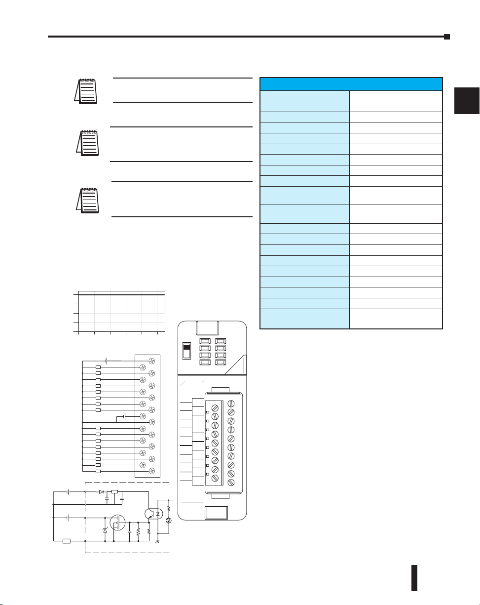
Chapter 2: Installation, Wiring and Specifications
Derating Chart
24VDC
Ambient Temperature (°C/°F)
0
4
8
12
16
Points
0
1
2
3
5
6
7
24V
0
1
2
3
0V
4
5
6
7
4
L
L
L
L
L
L
L
L
L
L
L
L
L
L
L
L
A
B
10.2-26.4
VDC 0.25A
CLASS2
OUT 12-24
F2–16TD2P
VDC
0
1
2
3
4
5
6
7
V1
4
5
6
7
0V
4
5
6
3
2
1
0
24V
3
2
1
0
7
A
B
+
When the A/B switch is in the A position,
the LEDs display the output status of the
module’s first 8 output points. Positon B
displays the output status of the module’s second group of 8 output points.
0
10 20 30 40 50 55°C
131°F
32 50 68 86 104 122
V1
12–24VDC
+
24V
V1
L
+–
24VDC
0V
OUTPUT
Reg
12–24VDC
+
Optical
Isolator
F2–16TD2P, DC Output with Fault Protection
NOTE: Not supported in D2-230, D2-240
and D2-250 CPUs.
NOTE: Supporting Firmware:
D2-250-1 must be V4.80 or later
D2-260 must be V2.60 or later
NOTE: This module does not currently
support Think & Do 8.0. It does not
support Think & Do Live! or Studio.
F2-16TD2P DC Output with Fault Protection
Inputs per module
Outputs per module
Commons per module
Output type
Operating voltage
Peak voltage
AC frequency
ON voltage drop
Overcurrent trip
Maximum load current
Maximum OFF current
Base power required 5V
OFF to ON response
ON to OFF response
Terminal type
Status indicators
Weight
Fuses
External DC required
External DC overvoltage
shutdown
16 (status indication)
16 (current sourcing)
1
NMOS FET (open source)
10.2 -26.4 VDC, external
40 VDC
N/A
0.7 V (output current 0.5 A)
0.6 A min., 1.2A max.
0.25 A continuous, 0.5 A
peak
Jumper J6 installed: 200 A;
J6 removed: 30 A
70 mA
0.5 ms
0.5 ms
Removable (D2-16IOCON)
Logic Side
2.0 oz. (25g)
None
24 VDC /10% @ 50 mA
27 V, outputs are restored
when voltage is within limits
DL205 User Manual, 4th Edition, Rev. B
1
2
3
4
5
6
7
8
9
10
11
12
13
14
A
B
C
D
2–41
Page 81

Chapter 2: Installation, Wiring and Specifications
D2–32TD1, DC Output
1
Outputs per Module
Commons per Module
2
Output Type
Operating Voltage
Peak Voltage
3
ON Voltage Drop
Minimum Load Current
4
Max Load Current
Max Leakage Current
Max Inrush Current
5
Base Power Required 5VDC
OFF to ON Response
6
ON to OFF Response
Terminal Type (not included)
7
Status Indicator
Weight
8
Fuses
External DC Power Required
1
9
Connector sold separately.
See Terminal Blocks and Wiring for wiring options.
D2-32TD1 DC Output
10
32 (current sinking)
4 (8 I/O terminal points)
NPN open collector
12-24 VDC
30 VDC
0.5 VDC maximum
0.2 mA
0.1A/point; 3.2A per module
0.1 mA @ 30 VDC
150 mA for 10 ms
350 mA
0.5 ms
0.5 ms
removable 40-pin connector
Module activity (no I/O status
indicators)
2.1 oz. (60g)
None
20-28 VDC max. 120 mA (all
points on)
D2–32TD2, DC Output
D2-32TD2 DC Output
Outputs per Module
Commons per Module
Output Type
Operating Voltage
Peak Voltage
ON Voltage Drop
Minimum Load Current
Max Load Current
Max Leakage Current
Max Inrush Current
Base Power Required 5VDC
OFF to ON Response
1
ON to OFF Response
Terminal Type (not included)
Status Indicator
Weight
Fuses
1
Connector sold separately.
See Terminal Blocks and Wiring for wiring options.
32 (current sourcing)
4 (8 I/O terminal points)
Transistor
12 to 24 VDC
30 VDC
0.5 VDC @ 0.1 A
0.2 mA
0.1A/point; 0.8A/common
0.1 mA @ 30 VDC
150 mA @ 10 ms
350 mA
0.5 ms
0.5 ms
Removable 40-pin connector
Module activity (no I/O status
indicators)
2.1 oz (60g)
None
1
11
12
13
14
A
B
C
D
2–42
DL205 User Manual, 4th Edition, Rev. B
Page 82

Chapter 2: Installation, Wiring and Specifications
F2–08TA, AC Output D2–08TA, AC Output
F2-08TA AC Output
Outputs per Module
Commons per Module
Output Type
Operating Voltage
Peak Voltage
ON Voltage Drop
AC Frequency
Minimum Load Current
Max Load Current
Max Leakage Current
Peak One Cycle Surge
Current
Base Power Required 5VDC
OFF to ON Response
ON to OFF Response
Terminal Type (included)
Status Indicator
Weight
Fuses
8
2 (Isolated)
SSR (Triac with zero crossover)
24-140 VAC
140 VAC
1.6 V(rms) @ 1.5A
47 to 63 Hz
50 mA
1.5A / pt @ 30ºC
1.0A / pt @ 60ºC
4.0A / common; 8.0A / module
@ 60ºC
0.7 mA(rms)
15A
250 mA
0.5 ms - 1/2 cycle
0.5 ms - 1/2 cycle
Removable; D2-8IOCON
Logic side
3.5 oz.
None
D2-08TA AC Output
Outputs per Module
Commons per Module
Output Type
Operating Voltage
Peak Voltage
ON Voltage Drop
AC Frequency
Minimum Load Current
Max Load Current
Max Leakage Current
Max Inrush Current
Base Power Required 5VDC
OFF to ON Response
ON to OFF Response
Terminal Type (included)
Status Indicator
Weight
Fuses
8
1 (2 I/O terminal points)
SR (Triac)
S
5-264 VAC
1
264 VAC
< 1.5 VAC (>0.1A)
< 3.0 VAC (<0.1A)
47 to 63 Hz
10 mA
0.5A/point; 4A/common
4 mA (264 VAC, 60 Hz)
1.2 mA (100 VAC, 60 Hz)
0.9 mA (100 VAC, 50 Hz)
10A for 10 ms
250 mA
1 ms
1 ms + 1/2 cycle
Removable; D2-8IOCON
Logic side
2.8 oz. (80g)
1 per common, 6.3A slow blow,
non-replaceable
1
2
3
4
5
6
7
8
9
10
11
12
13
14
A
B
C
D
DL205 User Manual, 4th Edition, Rev. B
2–43
Page 83
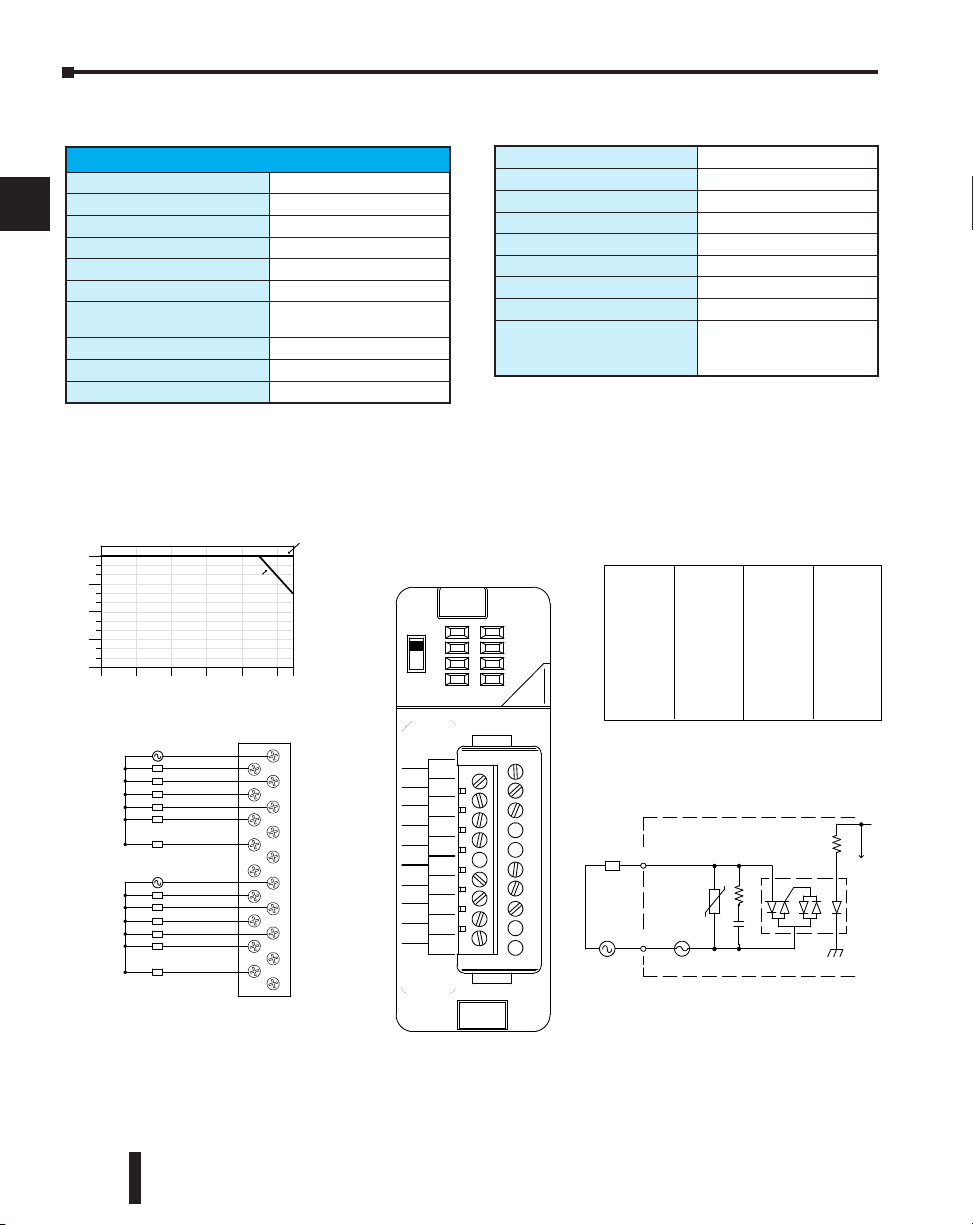
Chapter 2: Installation, Wiring and Specifications
Addres ses Use d
Yes
Yes
Yes
Yes
Yes
Points
Yn+0
Yn+1
Yn+2
Yn+3
Yn+4
Yn+5 Yes
Us e d?
NoYn+6
Yn+7 No
n is the starting addr ess
Yes
Yes
Yes
Yes
Yes
Points
Yn+10
Yn+11
Yn+12
Yn+13
Yn+14
Yn+15 Yes
Us e d?
NoYn+16
Yn+17 No
Optica l
COM
Isolator
OUTP UT
To LE D
Interna l module circuitry
3.15A
15--132
L
0
3
6
9
12
Points
VAC
250mA / Pt.
300mA / Pt.
0
1
2
3
5
NC
NC
NC
0
1
2
3
CB
4
5
NC
NC
CA
4
L
L
L
L
L
L
L
L
L
L
15--132 VAC
15--132 VAC
0 10 20 30 40 50 55
Ambient Tempe rature ( ˚C/˚F)
32 50 68 86 104 122 131
C˚
F˚
A
B
15--132VAC
10mA--0.3A
D2--12TA
O UT 18--110
D2--12TA
VAC
0
1
2
3
4
5
CA
4
5
CB
4
5
3
2
1
0
3
2
1
0
50/60 Hz
L
L
Derating Chart
D2–12TA, AC Output
1
Outputs per Module
Outputs Points Consumed
2
Commons per Module
Output Type
3
Operating Voltage
Peak Voltage
4
ON Voltage Drop
AC Frequency
5
Minimum Load Current
Max Load Current
D2-12TA AC Output
6
7
8
9
12
6 (four unused, see chart below)
1
2 (isolated)
SSR (Triac)
15-132 VAC
132 VAC
< 1.5VAC (>50mA)
< 4.0VAC (<50mA)
47 to 63 Hz
10 mA
0.3A/point; 1.8A/common
Max Leakage Current
Max Inrush Current
Base Power Required 5VDC
OFF to ON Response
ON to OFF Response
Terminal Type (included)
Status Indicator
Weight
Fuses
mA (132 VAC, 60 Hz)
2
10A for 10 ms
50 mA
3
1 ms
1 ms + 1/2 cycle
Removable; D2-16IOCON
Logic side
2.8 oz. (80g)
(2) 1 per common
3.15A slow blow, replaceable
Order D2-FUSE-1 (5 per pack)
10
11
12
13
14
A
B
C
D
2–44
DL205 User Manual, 4th Edition, Rev. B
Page 84
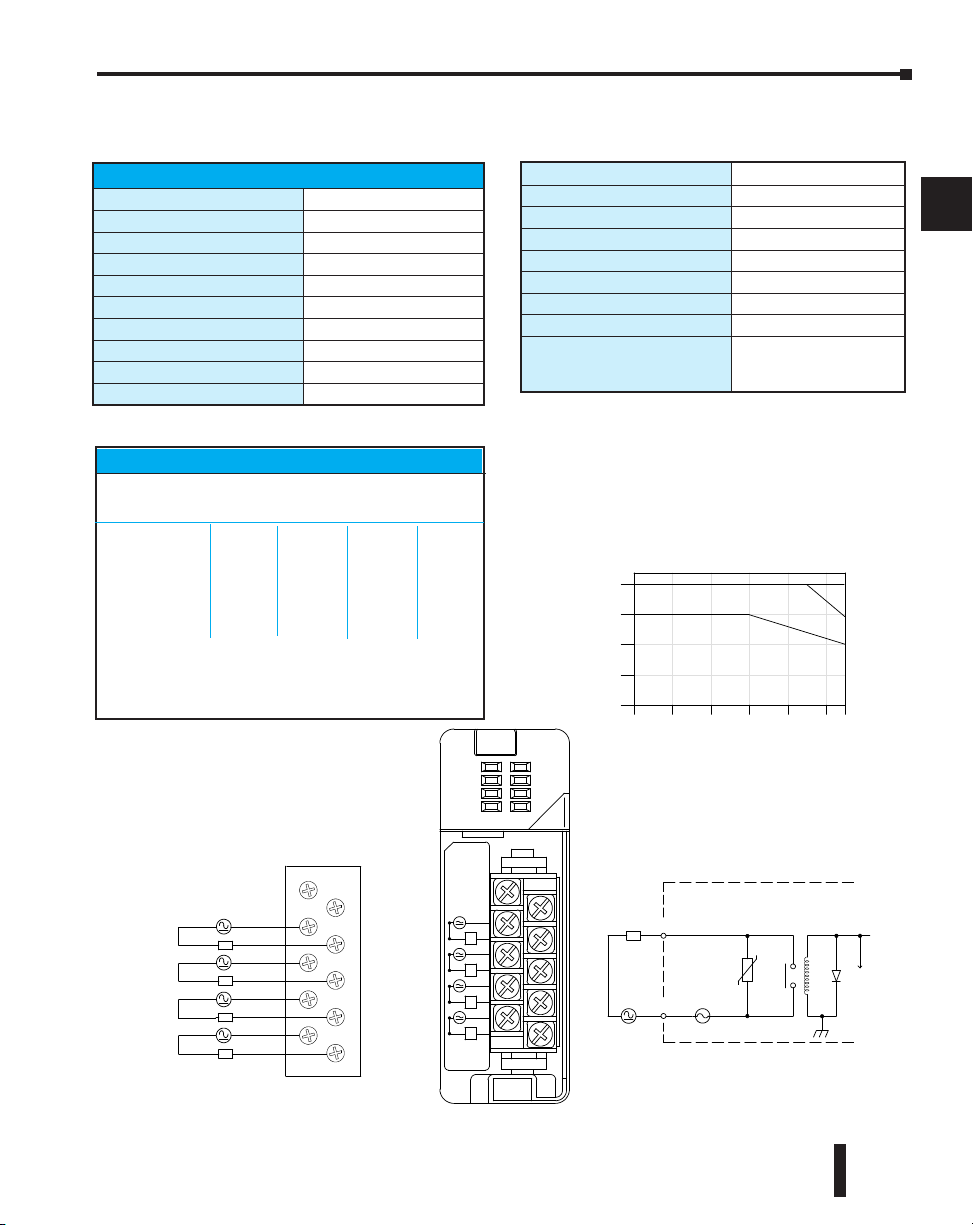
D2–04TRS, Relay Output
NC
NC
C0
C1
C2
C3
0
1
2
3
L
L
L
L
5--30 VDC
NC
NC
C0
0
C1
1
C2
2
C3
3
5-240VAC
4A50/ 60Hz
D2--04 TR S
OU T RE LAY
D2--04TRS
0
1
2
3
L
5--30VDC
10mA--4A
L
L
L
5--240 VAC
0
1
2
3
4
0
10 20 30 40 50 55
Ambient Tempera ture (˚C/˚F )
32
50 68 86 104 122 131
C˚
F˚
Points
2A /
Pt.
3A /
Pt.
4A /
Pt.
COM
OUTP UT
To LE D
Internal module circuitry
6.3A
5--240 VAC
L
5--30 VDC
Derating Chart
D2-04TRS Relay Output
Outputs per Module
Outputs Points Consumed
Commons per Module
Output Type
Operating Voltage
Peak Voltage
ON Voltage Drop
AC Frequency
Minimum Load Current
Max Load Current (resistive)
4
(only 1st 4pts. are used)
8
4 (isolated)
Relay, form A (SPST)
5-30 VDC / 5-240 VAC
30 VDC, 264 VAC
0.72 VDC maximum
47 to 63 Hz
10 mA
4A/point; 8A/module (resistive)
Chapter 2: Installation, Wiring and Specifications
Max Leakage Current
Max Inrush Current
Base Power Required 5VDC
OFF to ON Response
ON to OFF Response
Terminal Type (included)
Status Indicator
Weight
Fuses
0.1 mA @ 264 VAC
5A for < 10 ms
250 mA
10 ms
10 ms
Removable; D2-8IOCON
Logic side
2.8 oz. (80 g)
1 per point
6.3A slow blow, replaceable
Order D2-FUSE-3 (5 per pack)
1
2
3
4
5
6
Typical Relay Life (Operations)
Voltage &Load Current
Type of Load 1A 2A 3A 4A
24 VDC Resistive 500k 200k 100k 50k
24 VDC Solenoid 100k 40k –– –
110 VAC Resistive 500k 250k 150k 100k
110 VAC Solenoid 200k 100k 50k –
220 VAC Resistive 350k 150k 100k 50k
220 VAC Solenoid 100k 50k –– ––
At 24 VDC, solenoid (inductive) loads over 2A cannot be used.
At 100 VAC, solenoid (inductive) loads over 3A cannot be used.
At 220 VAC, solenoid (inductive) loads over 2A cannot be used.
DL205 User Manual, 4th Edition, Rev. B
7
8
9
10
11
12
13
14
A
B
C
D
2–45
Page 85
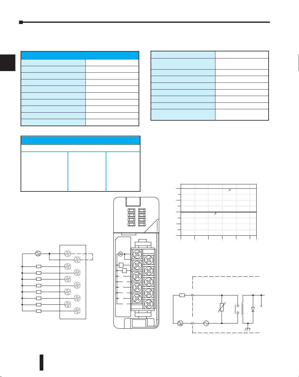
Chapter 2: Installation, Wiring and Specifications
0
2
4
6
8
Points
0.5A / P t.
COM
OUTP UT
To L E D
Internal module circuitry
6.3A
5--240 VAC
L
5--30 VDC
1A/Pt.
C
C
0
1
2
3
4
5
6
7
Internally
connected
L
L
L
L
L
L
L
L
5--240 VAC
5--30 VDC
0 10 20 30 40 50 55
Ambient Temperature (˚C/˚F)
32 50 68 86 104 122 131
C˚
F˚
C
C
0
4
1
5
2
6
3
7
5-240VAC
1A50/ 60Hz
D2--08 TR
OU T RE LAY
D2--08TR
0
1
2
3
4
5
6
7
L
L
5--30V D C
5mA--1A
Derating Chart
D2–08TR, Relay Output
1
Outputs per Module
2
Outputs Points Consumed
Commons per Module
3
Output Type
Operating Voltage
Peak Voltage
4
ON Voltage Drop
AC Frequency
5
Minimum Load Current
Max Load Current (resistive)
6
D2-08TR Relay Output
8
8
1 (2 I/O terminals)
Relay, form A (SPST)
5-30 VDC; 5-240 VAC
30 VDC, 264 VAC
N/A
47 to 60 Hz
5mA @ 5VDC
1A/point; 4A/common
Max Leakage Current
Max Inrush Current
Base Power Required 5VDC
OFF to ON Response
ON to OFF Response
Terminal Type (included)
Status Indicator
Weight
Fuses
.1 mA @265 VAC
0
utput: 3A for 10 ms
O
ommon: 10A for 10 ms
C
250 mA
12 ms
10 ms
Removable; D2-8IOCON
Logic side
3.9 oz. (110g)
One 6.3A slow blow, replaceable
Order D2-FUSE-3 (5 per pack)
7
8
9
10
11
12
13
14
A
B
C
D
2–46
Typical Relay Life (Operations)
Voltage/Load Current Closures
24 VDC Resistive 1A 500k
24 VDC Solenoid 1A 100k
110 VDC Resistive 1A 500k
110 VDC Solenoid 1A 200k
220 VAC Resistive 1A 350k
220 VAC Solenoid 1A 100k
DL205 User Manual, 4th Edition, Rev. B
Page 86
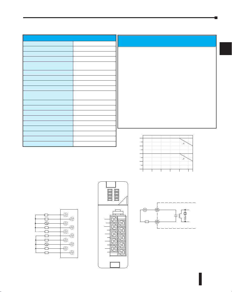
OUT R ELAY
F2--08TR
0
1
2
3
4
5
12--250VAC
10A 50/ 60Hz
12--28VDC
10ma--10A
6
7
L
Common
NO
Typical Cir cuit
12--250VAC
12--28VDC
Internal Circuitry
0
2
4
6
8
0 10 20 30 40 50 55
Ambient Temperature (°C/°F)
32 50 68 86 104 122 131C°F°
10 A/pt.
Number
Points On
(100% duty
cycle)
NO 4
NO 5
C4-7
NO 2
NO 3
NO 1
C0-3
NO 0
NO 6
NO 7
Derating Chart
L
L
L
L
L
L
L
L
3 A/pt.
2.5 A/pt.
5A/pt.
F2–08TR, Relay Output
Chapter 2: Installation, Wiring and Specifications
Outputs per Module
Outputs Points Consumed
Commons per Module
Output Type
Operating Voltage
Peak Voltage
ON Voltage Drop
AC Frequency
Minimum Load Current
Max Load Current (resistive)
Max Leakage Current
Max Inrush Current
Base Power Required 5VDC
OFF to ON Response
ON to OFF Response
Terminal Type (included)
Status Indicator
Weight
Fuses
F2-08TR Relay Output
8
8
2 (isolated), 4-pts. per common
, Form A (SPST normally open)
8
7A @ 12-28 VDC, 12-250VAC;
0.5A @ 120 VDC
150 VDC, 265 VAC
N/A
47 to 63Hz
10 mA @ 12 VDC
10A/point 33(subject to derating)
Max of 10A/common
N/A
12A
670 mA
15 ms (typical)
5 ms (typical)
Removable; D2-8IOCON
Logic side
5.5 oz. (156g)
None
Typical Relay Life1(Operations) at Room
Voltage & Load Current
Type of Load
24 VDC Resistive 10M 600k 300k
24 VDC Solenoid - 150k 75k
110 VDC Resistive – 600k 300k
110 VDC Solenoid – 500k 200k
220 VAC Resistive – 300k 150k
220 VAC Solenoid – 250k 100k
1) Contact life may be extended beyond those values shown with the
use of arc suppression techniques described in the DL205 User
Manual. Since these modules have no leakage current, they do not
have built-in snubber. For example, if you place a diode across a
24 VDC inductive load, you can significantly increase the life of the
relay.
2) At 120 VDC 0.5A resistive load, contact life cycle is 200k cycles.
3) Normally closed contacts have 1/2 the current handling
capability of the normally open contacts.
2
DL205 User Manual, 4th Edition, Rev. B
Temperature
50mA 5A 7A
1
2
3
4
5
6
7
8
9
10
11
12
13
14
A
B
C
D
2–47
Page 87
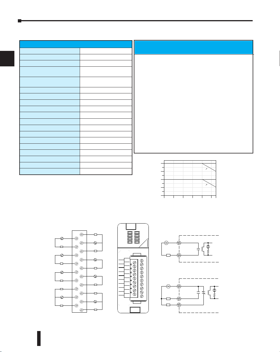
Chapter 2: Installation, Wiring and Specifications
12--250VAC
7A50/ 60Hz
OUT REL AY
F2--08TRS
0
1
2
3
4
5
NO 0
C0
NC 0
C3
NO 3
C5
NO 5
NC 7
C7
NO 6
C6
NC 6
NO 4
C4
NO 2
C2
NO 1
C1
NO7
12--28VDC
10ma--7A
6
7
L
Common
NO
Typica l Circ uit
L
Common
NO
NC
L
12--250VAC
12--28VDC
12--250VAC
12--28VDC
Internal Circuitry
Internal Circuitry
Typica l Circ uit
(Points 0, 6, & 7 only)
(po int s 1,2,3,4,5)
0
2
4
6
8
5A/pt.
0 102030405055
AmbientTemperature (˚C/˚F)
32 50 68 86 104 122 131
C˚
F˚
4A/
pt.
7A/pt.
6A/
pt.
Number
Points On
(100% duty
cycle)
C6
C7
NC 6
NC 7
NO 4
NO 5
C4
C5
NO 2
NO 3
C2
C3
NO 1
NC 0
C1
C0
NO 0
NO 6
NO 7
L
12--28VDC
12--250VAC
L
12--28VDC
12--250VAC
L
12--28VDC
12--250VAC
L
12--28VDC
12--250VAC
L
12--28VDC
12--250VAC
L
norm ally clos ed
L
12--28VDC
12--250VAC
L
norm ally clos ed
L
12--28VDC
12--250VAC
L
12--28VDC
12--250VAC
L
norm ally clos ed
Derating Chart
F2–08TRS, Relay Output
1
2
3
4
5
6
7
8
9
10
11
12
13
14
F2-08TRS Relay Output
Outputs per Module
Outputs Points Consumed
Commons per Module
Output Type
Operating Voltage
Peak Voltage
ON Voltage Drop
AC Frequency
Minimum Load Current
Max Load Current (resistive)
Max Leakage Current
Max Inrush Current
Base Power Required 5VDC
OFF to ON Response
ON to OFF Response
Terminal Type (included)
Status Indicator
Weight
Fuses
8
8
8 (isolated)
3, Form C (SPDT)
5, Form A (SPST normally open)
7A @ 12-28 VDC, 12-250 VAC
0.5A @ 120VDC
150 VDC, 265 VAC
N/A
47 to 63Hz
10 mA @ 12 VDC
7A/point 33(subject to derating)
N/A
12A
670 mA
15 ms (typical)
5 ms (typical)
Removable; D2-16IOCON
Logic side
5.5oz. (156g)
None
Typical Relay Life1(Operations) at Room
Temperature
Voltage & Load Current
Type of Load
24 VDC Resistive 10M 600k 300k
24 VDC Solenoid - 150k 75k
110 VDC Resistive – 600k 300k
110 VDC Solenoid – 500k 200k
220 VAC Resistive – 300k 150k
220 VAC Solenoid – 250k 100k
1) Contact life may be extended beyond those values shown with the
use of arc suppression techniques described in the DL205 User
Manual. Since these modules have no leakage current, they do not
have built-in snubber. For example, if you place a diode across a
24 VDC inductive load, you can significantly increase the life of the
relay.
2) At 120 VDC 0.5A resistive load, contact life cycle is 200k cycles.
3) Normally closed contacts have 1/2 the current handling
capability of the normally open contacts.
2
50mA 5A 7A
A
B
C
D
2–48
DL205 User Manual, 4th Edition, Rev. B
Page 88
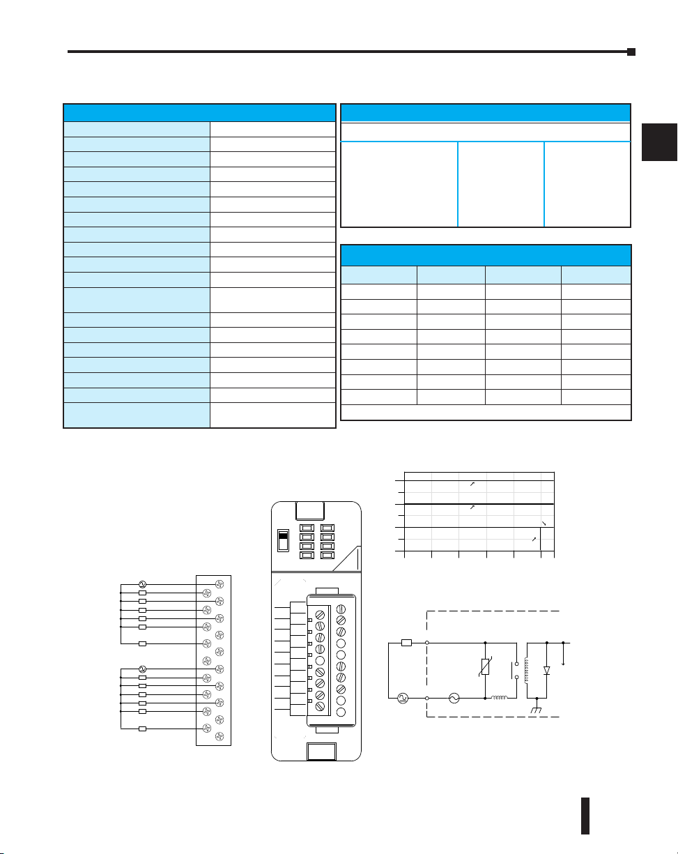
D2–12TR, Relay Output
A
B
5--240VAC
1.5A 50/60Hz
D2--12T R
OU T REL AY
D2-- 12TR
0
1
2
3
4
5
CA
4
5
CB
4
5
3
2
1
0
3
2
1
0
5--30VDC
0
4
8
12
Points
COM
OUTP UT
To LE D
Internal module circuitry
4A
5--240 VAC
L
5--30 VDC
0.5A / Pt.
0 10 20 30 40 50 55
Ambient Temperature (˚C/˚F)
32 50 68 86 104 122 131
C˚
F˚
1.5A / Pt.
0.75A / Pt.
5mA--1.5A
0
1
2
3
5
NC
NC
NC
0
1
2
3
CB
4
5
NC
NC
CA
4
L
L
L
L
L
L
L
L
L
L
L
L
5--240 VAC
5--30 VDC
5--240 VAC
5--30 VDC
1.25A / Pt.
Derating Chart
D2-12TR Relay Output
2
Outputs per Module
Outputs Points Consumed
Commons per Module
Output Type
Operating Voltage
Peak Voltage
ON Voltage Drop
AC Frequency
Minimum Load Current
Max Load Current (resistive)
Max Leakage Current
Max Inrush Current
Base Power Required 5VDC
OFF to ON Response
ON to OFF Response
Terminal Type (included)
Status Indicator
Weight
Fuses
1
16 (four unused, see chart below)
(6-pts. per common)
2
Relay, form A (SPST)
5-30 VDC; 5-240 VAC
30 VDC; 264 VAC
N/A
47 to 60 Hz
5 mA @ 5VDC
1.5 A/point; Max of 3A/common
0.1 mA @ 265 VAC
Output: 3A for 10 ms
Common: 10A for 10 ms
450 mA
10 ms
10 ms
Removable; D2-16IOCON
Logic side
4.6 oz. (130g)
(2) 4A slow blow, replaceable
Order D2-FUSE-4 (5 per pack)
Chapter 2: Installation, Wiring and Specifications
Typical Relay Life (Operations)
Voltage/Load Current Closures
24 VDC Resistive 1A 500k
24 VDC Solenoid 1A 100k
110 VDC Resistive 1A 500k
110 VDC Solenoid 1A 200k
220 VAC Resistive 1A 350k
220 VAC Solenoid 1A 100k
Addresses Used
Points Used? Points Used?
Yn+0 Yes Yn+10 Yes
Yn+1 Yes Yn+11 Yes
Yn+2 Yes Yn+12 Yes
Yn+3 Yes Yn+13 Yes
Yn+4 Yes Yn+14 Yes
Yn+5 Yes Yn+15 Yes
Yn+6 No Yn+16 No
Yn+7 No Yn+17 No
n is the starting address
1
2
3
4
5
6
7
8
9
10
11
12
DL205 User Manual, 4th Edition, Rev. B
13
14
A
B
C
D
2–49
Page 89
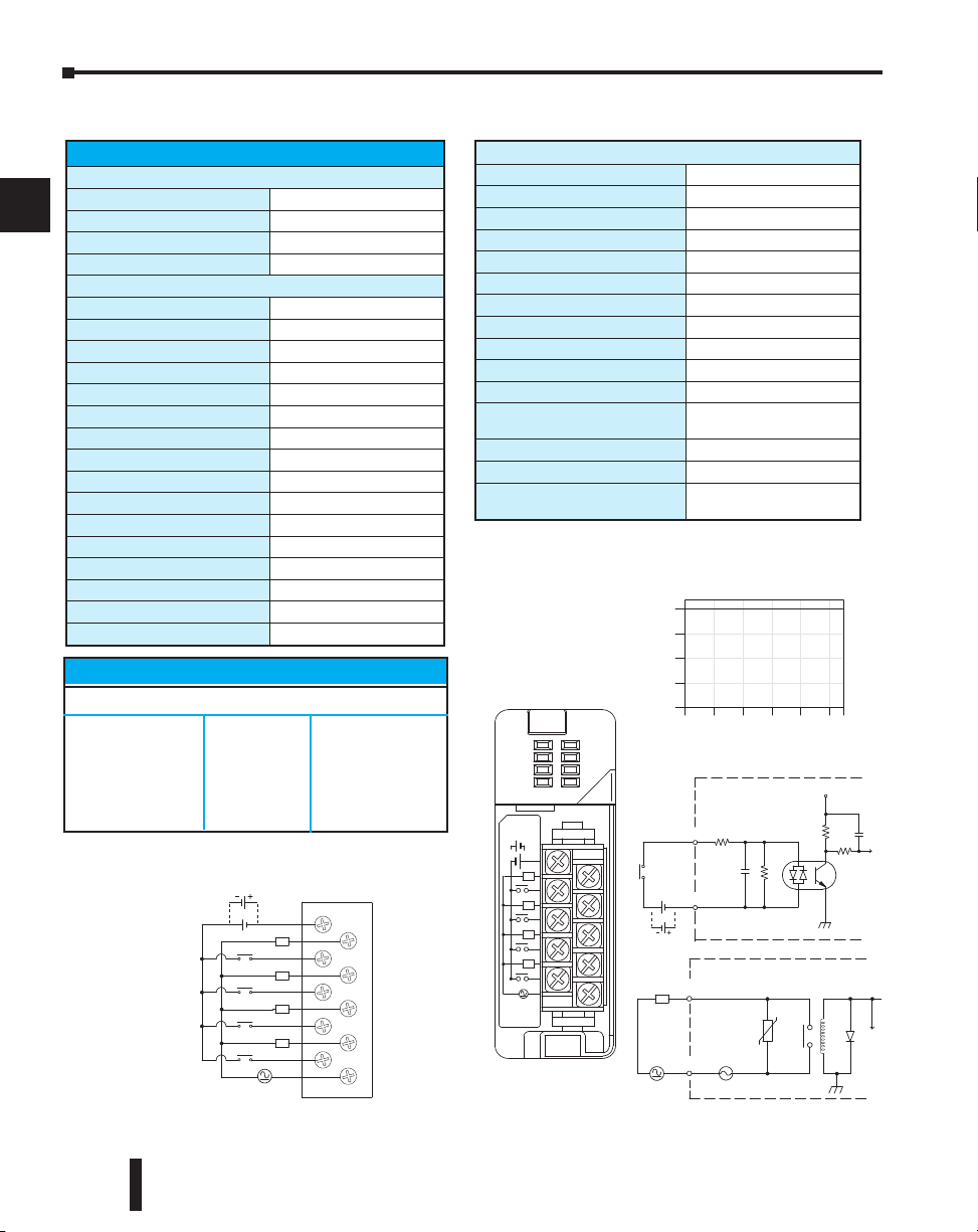
Chapter 2: Installation, Wiring and Specifications
CA
0
0
1
1
2
2
3
3
CB
D2--0 8CDR
20--28VDC
8mA
L
IN/ 24VDC
D2-- 08CDR
RELAY
0
1
2
3
0
1
2
3
OUT
AB
0
1
2
3
4
Points
Out puts
1A/Pt.
Derating Chart
COM
OUTP UT
To LE D
Internal module circuitry
6.3A
5--240 VAC
L
5--30 VDC
CA
O
0
1
2
3
1
2
3
CB
L
5--240 VAC
5--30 VDC
0 10 20 30 40 50 55
Ambient Temperature (°C/°F)
32 50 68 86 104 122131C°F°
L
L
L
5--240VAC
1A50/ 60Hz
5--30VDC
5mA--1A
Inputs
5mA /
Pt.
Optica l
COM
Isolator
INP UT
24VDC
V+
To LE D
Internal module circuitry
+
L
L
L
24VDC
+--
Sink
Source
Sink
Source
D2–08CDR, 4 pt. DC Input / 4pt. Relay Output
1
2
3
4
5
6
7
8
9
10
11
12
13
14
A
B
C
D
2–50
D2-08CDR 4-pt. DC In / 4pt. Relay Out
General Specifications
Base Power Required 5VDC
Terminal Type (included)
Status Indicator
Weight
200 mA
Removable; D2-8IOCON
Logic side
3.5 oz. (100 g)
Input Specifications
Inputs per Module
Input Points Consumed
Commons per Module
Input Voltage Range
Peak Voltage
ON Voltage Level
OFF Voltage Level
AC Frequency
Input Impedance
Input Current
Maximum Current
Minimum ON Current
Maximum OFF Current
OFF to ON Response
ON to OFF Response
Fuses (input circuits)
4 (sink/source)
8 (only first 4-pts. are used)
1
20-28 VDC
30 VDC
19 VDC minimum
7 VDC maximum
N/A
4.7 k
5 mA @ 24 VDC
8 mA @ 30 VDC
4.5 mA
1.5 mA
1 to 10 ms
1 to 10 ms
None
Typical Relay Life (Operations)
Voltage/Load Current Closures
24 VDC Resistive 1A 500k
24 VDC Solenoid 1A 100k
110 VAC Resistive 1A 500k
110 VAC Solenoid 1A 200k
220 VAC Resistive 1A 350k
220 VAC Solenoid 1A 100k
DL205 User Manual, 4th Edition, Rev. B
Output Specifications
Outputs per Module
Outputs Points Consumed
Commons per Module
Output Type
Operating Voltage
Peak Voltage
ON Voltage Drop
AC Frequency
Minimum Load Current
Max Load Current (resistive)
Max Leakage Current
Max Inrush Current
OFF to ON Response
ON to OFF Response
Fuses (output circuits)
4
8 (only first 4-pts. are used)
1
elay, form A (SPST)
R
5-30 VDC; 5-240 VAC
30 VDC; 264 VAC
N/A
47 to 63 Hz
5 mA @ 5 VDC
1A/point ; 4A/module
0.1 mA @ 264 VAC
3A for < 100 ms
10 A for < 10 ms (common)
12 ms
10 ms
1 (6.3A slow blow, replaceable);
Order D2-FUSE-3 (5 per pack)
Page 90

Chapter 2: Installation, Wiring and Specifications
Glossary of Specification Terms
Inputs or Outputs Per Module
Indicates number of input or output points per module and designates current sinking,
current sourcing, or either.
Commons Per Module
Number of commons per module and their electrical characteristics.
Input Voltage Range
The operating voltage range of the input circuit.
Output Voltage Range
The operating voltage range of the output circuit.
Peak Voltage
Maximum voltage allowed for the input circuit.
AC Frequency
AC modules are designed to operate within a specific frequency range.
ON Voltage Level
The voltage level at which the input point will turn ON.
OFF Voltage Level
The voltage level at which the input point will turn OFF.
Input impedance
Input impedance can be used to calculate input current for a particular operating voltage.
Input Current
Typical operating current for an active (ON) input.
Minimum ON Current
The minimum current for the input circuit to operate reliably in the ON state.
Maximum OFF Current
The maximum current for the input circuit to operate reliably in the OFF state.
Minimum Load
The minimum load current for the output circuit to operate properly.
External DC Required
Some output modules require external power for the output circuitry.
ON Voltage Drop
Sometimes called “saturation voltage”, it is the voltage measured from an output point to its
common terminal when the output is ON at max. load.
1
2
3
4
5
6
7
8
9
10
11
12
13
14
A
B
C
D
DL205 User Manual, 4th Edition, Rev. B
2–51
Page 91

1
2
3
4
5
6
7
8
9
10
11
12
13
Chapter 2: Installation, Wiring and Specifications
Maximum Leakage Current
The maximum current a connected maximum load will receive when the output point is
OFF.
Maximum Inrush Current
The maximum current used by a load for a short duration upon an OFF to ON transition of
a output point. It is greater than the normal ON state current and is characteristic of
inductive loads in AC circuits.
Base Power Required
Power from the base power supply is used by the DL205 input modules and varies between
different modules. The guidelines for using module power is explained in the power budget
configuration section in Chapter 4–7.
OFF to ON Response
The time the module requires to process an OFF to ON state transition.
ON to OFF Response
The time the module requires to process an ON to OFF state transition.
Terminal Type
Indicates whether the terminal type is a removable or non-removable connector or a terminal.
Status Indicators
The LEDs that indicate the ON/OFF status of an input point. These LEDs are electrically
located on either the logic side or the field device side of the input circuit.
Weight
Indicates the weight of the module. See Appendix F for a list of the weights for the various
DL205 components.
Fuses
Protective devices for an output circuit, which stop current flow when current exceeds the
fuse rating. They may be replaceable or non–replaceable, or located externally or internally.
14
A
B
C
D
2–52
DL205 User Manual, 4th Edition, Rev. B
Page 92

CHAPTER
CHAPTER
CPU SPECIFICATIONS AND
CHAPTER
OPERATIONS
33
33
33
In This Chapter
CPU Overview . . . . . . . . . . . . . . . . . . . . . . . . . . . . . . . . . . . . . . . . .3–2
CPU General Specifications . . . . . . . . . . . . . . . . . . . . . . . . . . . . . . .3–4
CPU Base Electrical Specifications . . . . . . . . . . . . . . . . . . . . . . . . . . .3–5
CPU Hardware Setup . . . . . . . . . . . . . . . . . . . . . . . . . . . . . . . . . . . .3–6
Selecting the Program Storage Media . . . . . . . . . . . . . . . . . . . . . . .3–9
Using Battery Backup . . . . . . . . . . . . . . . . . . . . . . . . . . . . . . . . . . .3–14
CPU Operation . . . . . . . . . . . . . . . . . . . . . . . . . . . . . . . . . . . . . . .3–21
I/O Response Time . . . . . . . . . . . . . . . . . . . . . . . . . . . . . . . . . . . . .3–27
CPU Scan Time Considerations . . . . . . . . . . . . . . . . . . . . . . . . . . .3–29
PLC Numbering Systems . . . . . . . . . . . . . . . . . . . . . . . . . . . . . . . .3–35
Memory Map . . . . . . . . . . . . . . . . . . . . . . . . . . . . . . . . . . . . . . . . .3–37
DL230 System V-memory . . . . . . . . . . . . . . . . . . . . . . . . . . . . . . .3–41
DL240 System V-memory . . . . . . . . . . . . . . . . . . . . . . . . . . . . . . .3–43
DL250–1 System V-memory (DL250 also) . . . . . . . . . . . . . . . . . . .3–46
DL260 System V-memory . . . . . . . . . . . . . . . . . . . . . . . . . . . . . . .3–49
DL205 Aliases . . . . . . . . . . . . . . . . . . . . . . . . . . . . . . . . . . . . . . . . .3–52
DL230 Memory Map . . . . . . . . . . . . . . . . . . . . . . . . . . . . . . . . . . .3–53
DL240 Memory Map . . . . . . . . . . . . . . . . . . . . . . . . . . . . . . . . . . .3–54
DL250–1 Memory Map (DL250 also) . . . . . . . . . . . . . . . . . . . . . . .3–55
DL260 Memory Map . . . . . . . . . . . . . . . . . . . . . . . . . . . . . . . . . . .3–56
X Input/Y Output Bit Map . . . . . . . . . . . . . . . . . . . . . . . . . . . . . . .3–57
Control Relay Bit Map . . . . . . . . . . . . . . . . . . . . . . . . . . . . . . . . . .3–59
Stage Control/Status Bit Map . . . . . . . . . . . . . . . . . . . . . . . . . . . . .3–63
Timer and Counter Status Bit Maps . . . . . . . . . . . . . . . . . . . . . . . .3–65
Remote I/O Bit Map . . . . . . . . . . . . . . . . . . . . . . . . . . . . . . . . . . . .3–66
Page 93

Chapter 3: CPU Specifications and Operations
CPU Overview
1
2
3
4
5
6
7
8
9
10
11
12
13
14
A
B
The Central Processing Unit is the heart of the PLC. Almost all
system operations are controlled by the CPU, so it is important
that it is set-up and installed correctly. This chapter provides the
information needed to understand:
• The differences between the various models of CPUs
• The steps required to setup and install the CPU
General CPU Features
The DL230, DL240, DL250–1 and D2–260 are modular CPUs
which can be installed in 3, 4, 6, or 9 slot bases. All I/O modules
in the DL205 family will work with any of the CPUs. The
DL205 CPUs offer a wide range of processing power and program instructions. All offer RLL
and Stage program instructions (See Chapter 5). They also provide extensive internal
diagnostics that can be monitored from the application program or from an operator
interface.
DL230 CPU Features
The DL230 has 2.4K words of memory comprised of 2.0K of ladder memory and
approximately 400 words of V-memory (data registers). It has 92 different instructions
available for programming, and supports a maximum of 256 I/O points.
Program storage is in the factory-installed EEPROM. In addition to the EEPROM there is
also RAM on the CPU which will store system parameters, V-memory, and other data which
is not in the application program.
The DL230 provides one built-in RS-232 communication port, so you can easily connect a
handheld programmer or a personal computer without needing any additional hardware.
DL240 CPU Features
The DL240 has a maximum of 3.8K of memory comprised of 2.5K of ladder memory and
approximately 1.3K of V-memory (data registers). There are 129 instructions available for
program development and a maximum of 256 points local I/O and 896 points with remote
I/O are supported.
Program storage is in the factory-installed EEPROM. In addition to the EEPROM there is
also RAM on the CPU which will store system parameters, V-memory and other data which
is not in the application program.
The DL240 has two communication ports. The top port is the same port configuration as the
DL230. The bottom port also supports the DirectNET protocol, so you can use the DL240
in a DirectNET network. Since the port is RS-232, you must use an RS-232/RS-422
converter for multi-drop connections.
C
D
3–2
DL205 User Manual, 4th Edition, Rev. B
Page 94

Chapter 3: CPU Specifications and Operations
DL250–1 CPU Features
The DL250–1 replaces the DL250 CPU. It offers all the DL240 features, plus more program
instructions and a built–in Remote I/O Master port. It offers all the features of the DL250
CPU with the addition of supporting Local expansion I/O. It has a maximum of 14.8K of
program memory comprised of 7.6K of ladder memory and 7.2K of V-memory (data
registers). It supports a maximum of 256 points of local I/O and a maximum of 768 I/O
points (max. of two local expansion bases). In addition, port 2 supports up to 2048 points if
you use the DL250–1 as a Remote master. It includes an internal RISC–based microprocessor
for greater processing power. The DL250–1 has 240 instructions. The instructions are in
addition to the DL240 instruction set which include drum timers, a print function, floating
point math, PID loop control for 4 loops and the Intelligent Box (IBox) instructions.
The DL250–1 has a total of two built–in communications ports. The top port is identical to
the top port of the DL240, with the exception of the DirectNet slave feature. The bottom
port is a 15–pin RS-232/RS-422 port. It will interface with DirectSOFT and operator
interfaces, and provides DirectNet and Modbus RTU Master/Slave connections.
DL260 CPU Features
The DL260 offers all the DL250–1 features, plus ASCII IN/OUT and expanded Modbus
instructions. It also supports up to 1280 local I/O points by using up to four local expansion
bases. It has a maximum of 30.4K of program memory comprised of 15.8K of ladder
memory (saved on flash memory) and 14.6K of V-memory (data registers). It also includes an
internal RISC–based microprocessor for greater processing power. The DL260 has 297
instructions. In addition to those in the DL250–1 instruction set, the DL260 instruction set
includes table instructions, trigonometric instructions and support for 16 PID loops.
The DL260 has a total of two built–in communications ports. The top port is identical to the
top port of the DL250–1. The bottom port is a 15–pin RS-232/RS-422/RS-485 port. It will
interface with DirectSOFT (version 4.0 or later), operator interfaces, and provides DirectNet,
Modbus RTU Master/Slave connections. Port 2 also supports ASCII IN/OUT instructions.
1
2
3
4
5
6
7
8
9
10
11
12
DL205 User Manual, 4th Edition, Rev. B
13
14
A
B
C
D
3–3
Page 95
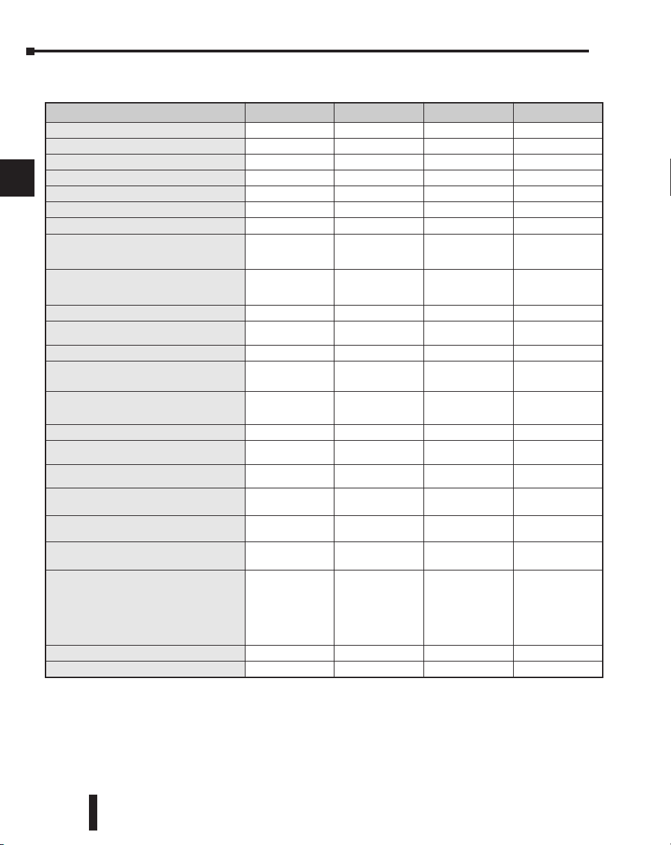
Chapter 3: CPU Specifications and Operations
CPU General Specifications
1
2
3
4
5
6
7
8
9
10
11
12
13
Total Program memory (words)
Ladder memory (words)
V-memory (words)
Non-volatile V Memory (words)
Boolean execution /K
RLL and RLL
Handheld programmer
DirectSOFT programming for Windows.
Built-in communication ports
EEPROM
Total CPU memory I/O points available
Local I/O points available
Local Expansion I/O points (including
local I/O and expansion I/O points)
Serial Remote I/O points (including
local I/O and expansion I/O points)
Serial Remote I/O Channels
Max Number of Serial Remote Slaves
Ethernet Remote I/O Discrete points
Ethernet Remote I/O Analog I/O
channels
Ethernet Remote I/O channels
Max Number of Ethernet slaves per
channel
Feature DL230 DL240 DL250–1 DL260
2.4K 3.8K 14.8K 30.4K
2048 2560 7680 (Flash) 15872 (Flash)
256 1024 7168 14592
128 256 No No
PLUS
Programming
4–6 ms 10–12 ms 1.9ms 1.9ms
Yes Yes Yes Yes
Yes Yes Yes Yes
Yes Yes Yes
One RS–232 Two RS–232
Standard on CPU Standard on CPU Flash Flash
256 (X,Y,CR) 896 (X,Y,CR) 2048 (X,Y,CR)
256 256 256 256
N/A N/A
N/A 896 2048 8192
N/A 2 8 8
N/A 7 Remote / 31 Slice 7 Remote / 31 Slice 7 Remote / 31 Slice
N/A 896 2048 8192
N/A Map into V–memory Map into V–memory Map into V–memory
N/A
N/A 16 16 16
14
I/O points per Remote channel
N/A
A
I/O Module Point Density
B
Slots per Base
4/8/12/16/32 4/8/12/16/32 4/8/12/16/32 4/8/12/16/32
3/4/6/9 3/4/6/9 3/4/6/9 3/4/6/9
limited by power
budget
16,384 (limited to
896 by CPU)
One RS–232
One RS–232 or
RS–422
768 (2 exp. bases
max.)
limited by power
budget
16,384 (16 fully
expanded H4–EBC
slaves using
V–memory and
bit–of–word
instructions)
Yes (requires
version 4.0 or
higher)
One RS–232
One RS–232,
RS–422 or RS–485
8192
(X,Y,CR,GX,GY)
1280 (4 exp. bases
max.)
limited by power
budget
16,384 (16 fully
expanded H4–EBC
slaves using
V–memory and
bit–of–word
instructions
C
D
3–4
DL205 User Manual, 4th Edition, Rev. B
Page 96

Feature DL230 DL240 DL250–1 DL260
Number of instructions available
(see Chapter 5 for details)
Control relays
Special relays (system defined)
Stages in RLL
Timers
Counters
Immediate I/O
Interrupt input (hardware / timed)
Subroutines
Drum Timers
Table Instructions
For/Next Loops
Math
ASCII
PID Loop Control, Built In
Time of Day Clock/Calendar
Run Time Edits
Supports Overrides
Internal diagnostics
Password security
System error log
User error log
Battery backup
PLUS
Chapter 3: CPU Specifications and Operations
92 129 240 297
256 256 1024 2048
112 144 144 144
256 512 1024 1024
64 128 256 256
64 128 128 256
Yes Yes Yes Yes
Yes / No Yes / Yes Yes / Yes Yes / Yes
No Yes Yes Yes
No No Yes Yes
No No No Yes
No Yes Yes Yes
Integer Integer
No No Yes, OUT Yes, IN/OUT
No No Yes, 4 Loops Yes, 16 Loops
No Yes Yes Yes
Yes Yes Yes Yes
No Yes Yes Yes
Yes Yes Yes Yes
Yes Yes Yes Yes
No Yes Yes Yes
No Yes Yes Yes
Yes (optional) Yes (optional) Yes (optional) Yes (optional)
Integer,
Floating Point
Integer,
Floating Point,
Trigonometric
1
2
3
4
5
6
7
8
9
10
11
12
CPU Base Electrical Specifications
Specification AC Powered Bases 24 VDC Powered Bases 125 VDC Powered Bases
D2–03B–1
Part Numbers
Input Voltage Range
Maximum Inrush Current
Maximum Power
Voltage Withstand (dielectric)
Insulation Resistance
Auxiliary 24 VDC Output
Fusing (internal to base
power supply)
100–240 VAC +10% –15%
30 A 10 A 20 A
80 VA 25 W 30 W
1 minute @ 1500 VAC between primary, secondary, field ground, and run relay
> 10 M⏲ at 500 VDC
20–28 VDC, less than 1V p-p
300 mA max.
non–replaceable 2 A @ 250 V
slow blow fuse;
external fusing recommended
D2–04B–1
D2–06B–1
D2–09B–1
10.2–28.8 VDC (24 VDC)
with less than 10% ripple
None
non–replaceable 3.15 A @
250 V slow blow fuse;
external fusing recommended
DL205 User Manual, 4th Edition, Rev. B
D2–03BDC1–1
D2–04BDC1–1
D2–06BDC1–1
D2–09BDC1–1
D2–06BDC2–1
D2–09BDC2–1
104–240 VDC +10% –15%
20–28 VDC, less than 1V p-p
300 mA max.
non–replaceable 2 A @ 250 V
slow blow fuse;
external fusing recommended
13
14
A
B
C
D
3–5
Page 97
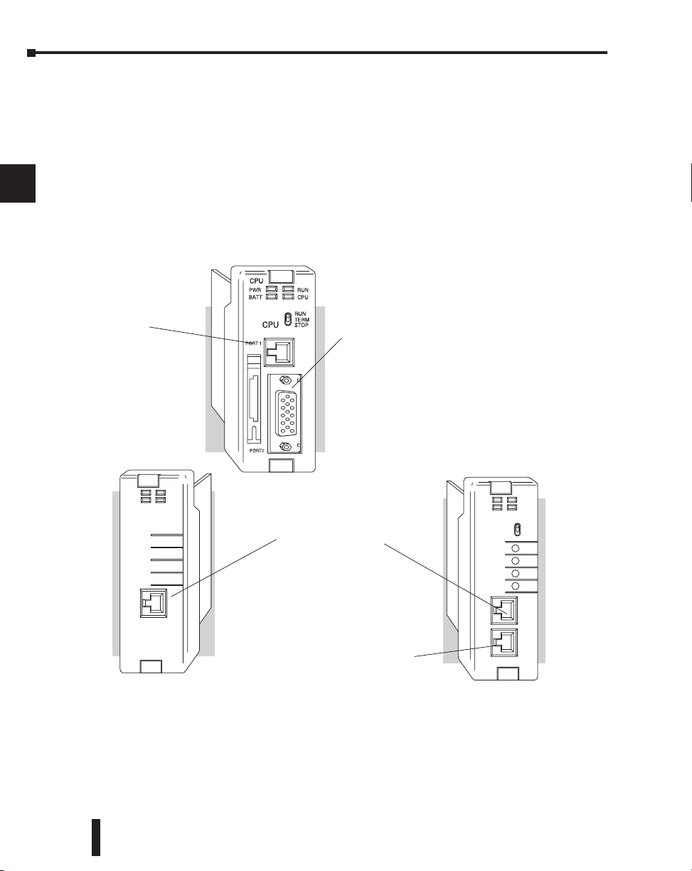
Chapter 3: CPU Specifications and Operations
RJ12 Phone Jack
RS-232, 9600 baud
Communication Port
–K-sequence
–DirectNET slave
–Modbus RTU slave
–easily connect
DirectSOFT,
handhelds, operator
interfaces, any DirectNet
master
Port 1
DL250–1 and DL260
Port 2
Additional DL260 Features
CH1
CH2
CH3
CH4
RUN
TERM
RUN
CPU
PWR
BATT
PORT 1
PORT 2
DL240
CPU
RUN
PWR
BATT
PORT 1?
CPU
RJ12 Phone Jack
RS-232, 9600 baud
Communication Port
–K-sequence
–easily connect
Direct SOFT, handhelds,
operator interfaces, etc.
Port 1
RJ12 Phone Jack
RS-232, up to 19.2K baud
Communication Port
–K-sequence
–DirectNET slave
–easily connect
DirectSOFT, handhelds,
operator interfaces, or any
DirectNet master
Port 2
15-pin HD Connector
RS-232/RS-422, up to 38.4K baud
Communication Port
–K-sequence
–DirectNET Master/Slave
–Modbus RTU Master/Slave
–easily connect
Direct SOFT,
handhelds, operator
interfaces, any DirectNet
or Modbus master or slave
DL260
Port 2
DL250–1 and DL260
–ASCII IN/OUT Instructions
–Extended Modbus Instructions
–RS-485 support
CPU
DL230
CPU Hardware Setup
1
Communication Port Pinout Diagrams
2
3
4
Cables are available that allow you to quickly and easily connect a Handheld Programmer or a
personal computer to the DL205 CPUs. However, if you need to build a cable(s), use the
pinout descriptions shown on the following pages. You can also use the Tech Support/Cable
Wiring diagrams located on our website.
The DL240, DL250–1 and DL260 CPUs have two ports while the DL230 has only one. All
of the CPUs require at least one RJ-12 connector. The DL250-1 and DL260 require one 15
pin D-shell connector.
5
6
7
8
9
10
11
12
13
14
A
B
C
D
3–6
DL205 User Manual, 4th Edition, Rev. B
Page 98
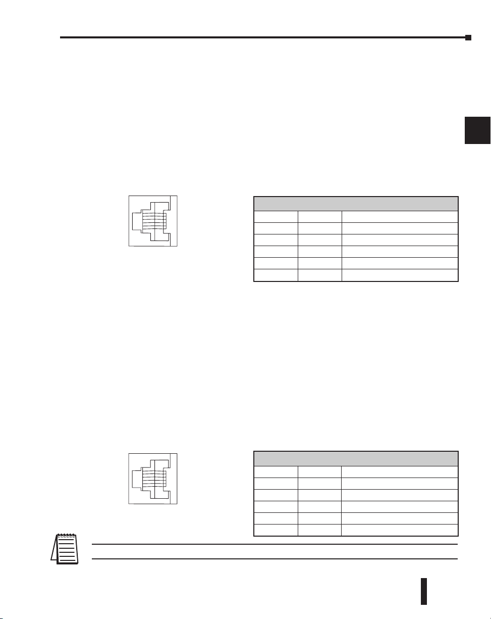
Chapter 3: CPU Specifications and Operations
ý
ý
þ
þ
230
240
250-1
260
ý
ý
þ
þ
230
240
250-1
260
6-pin Female
Modular Connector
1
6
6-pin Female
Modular Connector
1
6
Port 1 Specifications
The operating parameters for Port 1 on the DL230 and DL240 CPUs are fixed.
• 6-pin female modular (RJ12 phone jack) type connector
• K–sequence protocol (slave only)
• RS-232, 9600 baud
• Connect to DirectSOFT, D2–HPP, DV–1000, HMI panels
• Fixed station address of 1
• 8 data bits, one stop
• Asynchronous, Half–duplex, DTE
• Odd parity
1
2
3
4
5
Port 1 Specifications
Port 1 Pin Descriptions (DL230 and DL240)
1 0V Power (–) connection (GND)
2 5V Power (+) connection
3 RXD Receive Data (RS-232)
4 TXD Transmit Data (RS-232)
5 5V Power (+) connection
6 0V Power (–) connection (GND)
The operating parameters for Port 1 on the DL250–1 and DL260 CPU are fixed. This
applies to the DL250 as well.
• 6-pin female modular (RJ12 phone jack) type connector
• K–sequence protocol (slave only)
• DirectNET (slave only)
• Modbus RTU (slave only)
• RS-232, 9600 baud
• Connect to DirectSOFT, D2–HPP, DV1000 or DirectNET master
• 8 data bits, one start, one stop
• Asynchronous, Half–duplex, DTE
• Odd parity
Port 1 Pin Descriptions (DL250-1 and DL260)
1 0V Power (–) connection (GND)
2 5V Power (+) connection
3 RXD Receive Data (RS-232C)
4 TXD Transmit Data (RS-232C
5 5V Power (+) connection
6 0V Power (–) connection (GND)
NOTE: The 5V pins are rated at 200mA maximum, primarily for use with some operator interface units.
DL205 User Manual, 4th Edition, Rev. B
6
7
8
9
10
11
12
13
14
A
B
C
D
3–7
Page 99
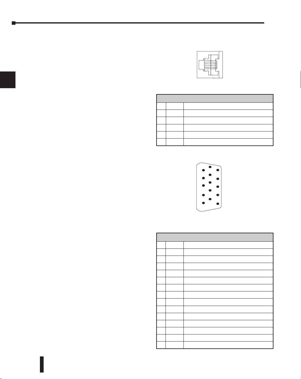
Chapter 3: CPU Specifications and Operations
6-pin Female
Modular Connector
1
6
15-pin Female
D Connector
1
6
11
5
10
15
ý
þ
ý
ý
230
240
250-1
260
ý
ý
þ
þ
230
240
250-1
260
Port 2 Specifications
1
2
3
4
5
6
The operating parameters for Port 2 on the DL240 CPU are configurable using Aux
functions on a programming device.
• 6-Pin female modular (RJ12 phone jack)
type connector
• K–sequence protocol, DirectNET (slave),
• RS-232, Up to 19.2K baud
• Address selectable (1–90)
• Connect to DirectSOFT, D2–HPP,
DV-1000, HMI, or DirectNET master
• 8 data bits, one start, one stop
• Asynchronous, Half–duplex, DTE
• Odd or no parity
Port 2 Specifications
7
8
9
10
11
12
13
14
A
B
C
Port 2 on the DL250-1 and DL260 CPUs is located on the 15-pin D-shell connector. It is
configurable using AUX functions on a programming device. This applies to the DL250 as
well.
• 15-Pin female D type connector
• Protocol: K-sequence, DirectNET
Master/Slave, Modbus RTU Master/Slave,
Remote I/O, (ASCII IN/OUT DL260 only)
• RS-232, non-isolated, distance within 15 m
(approx. 50 feet)
• RS-422, non-isolated, distance within
1000 m
• RS-485, non–isolated, distance within
1000m (DL260 only)
• Up to 38.4K baud
• Address selectable (1–90)
• Connects to DirectSOFT, D2–HPP, operator
interfaces, any DirectNET or Modbus
master/slave, (ASCII devices-DL260 only)
• 8 data bits, one start, one stop
• Asynchronous, Half–duplex, DTE Remote
I/O
• Odd/even/none parity
D
3–8
DL205 User Manual, 4th Edition, Rev. B
Port 2 Pin Descriptions (DL240 only)
1 0V Power (–) connection (GND)
2 5V Power (+) connection
3 RXD Receive Data (RS-232)
4 TXD Transmit Data (RS-232)
5 RTS Request to Send
6 0V Power (–) connection (GND)
Port 2 Pin Descriptions (DL250–1 / DL260)
1 5V 5 VDC
2 TXD2 Transmit Data (RS-232)
3 RXD2 Receive Data (RS-232)
4 RTS2 Ready to Send (RS–232)
5 CTS2 Clear to Send (RS–232)
6 RXD2 – Receive Data – (RS–422) (RS–485 DL260)
7 0V Logic Ground
8 0V Logic Ground
9 TXD2 + Transmit Data + (RS–422) (RS–485 DL260)
10 TXD2 – Transmit Data – (RS–422) (RS–485 DL260)
11 RTS2 + Request to Send + (RS–422) (RS–485 DL260)
12 RTS2 – Request to Send – (RS–422)(RS–485 DL260)
13 RXD2 + Receive Data + (RS–422) (RS–485 DL260)
14 CTS2 + Clear to Send + (RS422) (RS–485 DL260)
15 CTS2 – Clear to Send – (RS–422) (RS–485 DL260)
Page 100
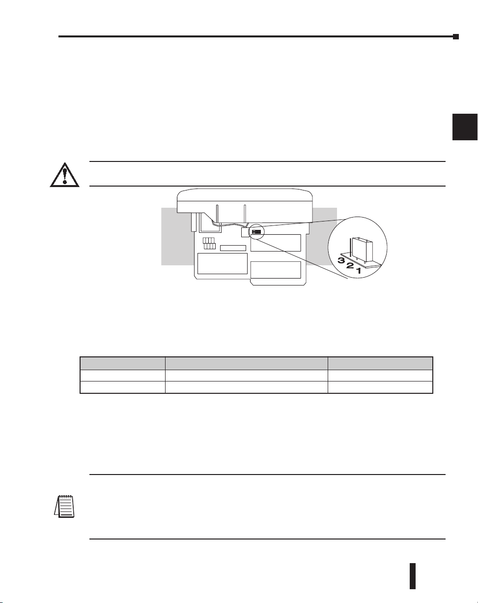
Chapter 3: CPU Specifications and Operations
Jumper in position
shown selects write
protect for EEPROM
EEPROM
ý
ý
þ
þ
230
240
250-1
260
Selecting the Program Storage Media
Built-in EEPROM
The DL230 and DL240 CPUs provide built-in EEPROM storage. This type of memory is
non-volatile and is not dependent on battery backup to retain the program. The EEPROM
can be electrically reprogrammed without being removed from the CPU. You can also set
Jumper 3, which will write protect the EEPROM. The jumper is set at the factory to allow
changes to EEPROM. If you select write protection by changing the jumper position, you
cannot make changes to the program.
WARNING: Do NOT change Jumper 2. This is for factory test operations. If you change Jumper 2, the
CPU will not operate properly.
1
2
3
4
5
6
7
8
9
EEPROM Sizes
The DL230 and DL240 CPUs use different sizes of EEPROMs. The CPUs come from the
factory with EEPROMs already installed. However, if you need extra EEPROMs, select one
that is compatible with the following part numbers.
CPU Type EEPROM Part Number Capacity
DL230 Hitachi HN58C65P–25 8K byte (2Kw)
DL240 Hitachi HN58C256P–20 32K byte (3Kw)
EEPROM Operations
There are many AUX functions specifically for use with an EEPROM in the Handheld
Programmer. This enables you to quickly and easily copy programs between a program
developed offline in the Handheld and the CPU. Also, you can erase EEPROMs, compare
them, etc. See the DL205 Handheld Programmer Manual for details on using these AUX
functions with the Handheld Programmer.
NOTE: If the instructions are supported in both CPUs and the program size is within the limits of the
DL230, you can move a program between the two CPUs. However, the EEPROM installed in the Handheld
Programmer must be the same size (or larger) than the CPU being used. For example, you could not install
a DL240 EEPROM in the Handheld Programmer and download the program to a DL230. Instead, if the
program is within the size limits of the DL230, use a DL230 chip in the Handheld when you obtain the
program from the DL240.
DL205 User Manual, 4th Edition, Rev. B
10
11
12
13
14
A
B
C
D
3–9
 Loading...