

Page 1
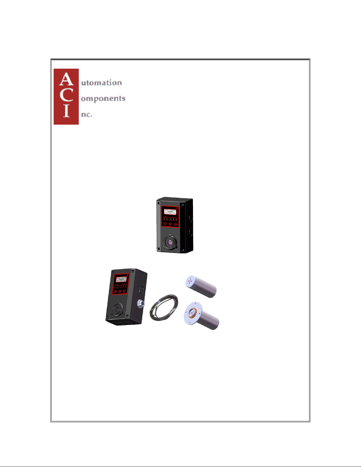
B5/B5 IR-Probe
GAS TRANSMITTER/SENSOR
B5
IR-Probe
INSTALLATION
OPERATION AND MAINTENANCE
MANUAL
AUTOMATION COMPONENTS, INC.
2305 PLEASANT VIEW ROAD | MIDDLETON, WI 53562
PHONE: (888) 967-5224 FAX: (608) 831-7407
Web: workaci.com
Page 2

B5 Operation And Maintenance Manual
1
READ BEFORE OPERATING ................................................................................................................... 2
1. SPECIFICATIONS .............................................................................................................................. 2
1.1 ELECTRICAL/MECHANICAL SPECIFICATIONS .......................................................................................... 2
1.2 SENSOR SPECIFICATIONS ........................................................................................................................ 4
2. INSTALLATION ................................................................................................................................. 6
2.1 ENCLOSURES PHYSICAL DIMENSIONS ..................................................................................................... 6
2.2 TERMINALS ............................................................................................................................................. 6
2.2.1 Wire and Cable ............................................................................................................................. 7
2.2.2 RS-485 Terminator ....................................................................................................................... 7
2.2.3 RS-485 Driver Replacement ......................................................................................................... 7
2.2.4 Relays Output ............................................................................................................................... 7
2.2.5 Note for B5: .................................................................................................................................. 8
2.2.6 Certification: ................................................................................................................................ 8
3. FUNCTION AND CONFIGURATION ............................................................................................. 9
3.1 INDICATORS ............................................................................................................................................ 9
3.1.1 RS485-TX/RX:............................................................................................................................ 9
3.1.2 Relay 1-3 LED: ........................................................................................................................... 9
3.2 TOOL FUNCTION ................................................................................................................................... 10
3.2.1 Enter Main Menu........................................................................................................................ 10
3.2.2 Hush Buzzer and Relay ............................................................................................................... 10
3.2.3 Reset Latched/Hushed ................................................................................................................ 10
3.2.4 Reset MENU Password .............................................................................................................. 10
3.2.5 Exit Tool Mode ........................................................................................................................... 10
3.3 MAIN MENU TREE ................................................................................................................................ 11
3.4 MENU “1_SYSTEM SETUP” .............................................................................................................. 12
3.4.1 System Settings ........................................................................................................................... 12
3.5 MENU “2_ZERO CAL” ........................................................................................................................ 15
3.5.1 Equipment Required ................................................................................................................... 15
3.5.2 Zeroing Calibration Procedure .................................................................................................. 15
3.6 MENU “3_SPAN CAL” ........................................................................................................................ 16
3.7 MENU “4_OUT TEST”......................................................................................................................... 17
3.8 MENU “5_VIEW SETTING” ............................................................................................................... 18
3.9 MENU “6_ALARM SETUP” ................................................................................................................ 19
3.10 MENU “7_RELAY STYLE” ............................................................................................................ 20
3.11 MENU “8_BUZZER STYLE” .......................................................................................................... 21
3.12 MENU “A_ALL DISABLE” ............................................................................................................ 21
3.13 MENU “B_SIMULATION” ............................................................................................................. 21
3.14 MENU “C_SITE SERVICE” AND “D_FACTROY SET” ................................................................. 21
4. BACNET PIC STATEMENT SUPPORTED BY B5 ...................................................................... 21
4.1 SMART SENSOR ASSEMBLY REPLACEMENT .......................................................................................... 21
4.1.1 Disassembling ............................................................................................................................ 21
4.1.2 Replacement Procedure.............................................................................................................. 22
4.1.3 Replacement Parts ...................................................................................................................... 23
4.1.4 Accessories ................................................................................................................................. 25
5. TROUBLESHOOTING .................................................................................................................... 26
85950-101-000 RB August 7, 2015
Page 3

B5 Operation And Maintenance Manual
2
Input Power:
24VDC nominal, range 18 to 30VDC, 0.3A DC Total Max.
24VAC nominal, range 15 to 24VAC, 0.3A AC Total Max.
Fuse:
F2 on Main Board: Polyswitch 750mA
the circuit is removed.
Sensor:
Combustible gases: Catalytic or NDIR
Carbon Dioxide: Non-Dispersive Infra-Red (NDIR)
Sampling:
Diffusion or Pump-through
READ BEFORE OPERATING
All individuals who have or will have the responsibility of using, maintaining, or
servicing this product must carefully read this manual. The product will perform as
designed only if it is used, maintained, and serviced in accordance with the
manufacturer’s instructions.
The B5 is a state-of-the-art transmitter that can operate as an independent, stand-alone
system or as part of an integrated system. Setup procedures are simplified with user
friendly push buttons and LCD menus.
The B5 and the B5 IR-Probe are the Q5 and Q5 IR-Probe with BACnet® MS/TP master
protocol. Therefore, the B5 and the B5 IR-Probe do not support the 4-20mA and VDC
analog output.
BACnet MS/TP protocol is a peer-to-peer, multiple master protocol based on token
passing. Only master nodes are allowed to send and receive tokens on the MSTP
network. Passive slave nodes on the other hand may only transmit data frames on the
network in response to a request from a master node. Passing the token represents
overhead in the sense that the messages used for managing the token do not carry data
that is useful to automation or monitoring.
The B5 and the B5 IR-Probe can be set to be a Master Node or a Slave Node in the field.
Factory default is slave node.
1. Specifications
1.1 Electrical/Mechanical Specifications
Polyswitch device resets after the fault is cleared and power to
Toxic gases and Oxygen: Electrochemical
85950-101-000 RB August 7, 2015
Page 4

B5 Operation And Maintenance Manual
3
Panel Indicators:
5 Status LED’s
• Relay2 Status (Red)
Display:
LCD graphic display c/w backlight
Keypad:
3 capacitive touch sensing Keys: F1, F2, F3
Relays:
3 Relays SPDT, Dry contacts
0.3A maximum at 125VAC (resistive load)
Buzzer:
80 db at 10 cm, 2700 Hz
Output Signal:
BACnet® MS/TP master /slave protocol
Enclosure Rating:
IP 66 & NEMA 4, 4X, 12 & 13
Operating Temperature:
-40°C to 70°C, depends on sensor specification
Ambient Humidity:
5% to 95% RH (non-condensing)
Storage Temperature:
0°C to 40°C, depends on sensor specification
Size:
150mm X 90mm X 65mm
Weight:
Less than 0.5lbs
• RS-485 TX Status (Green)
• RS-485 RX Status (Green)
• Relay1 Status (Red)
• Relay2 Status (Red)
• 1.0A maximum at 30 VDC (resistive load)
•
Buzzer 1, 2, 3: Programmable tone
Tone: chirp once / chirp twice / 50% duty cycle / constant ON
85950-101-000 RB August 7, 2015
Page 5

B5 Operation And Maintenance Manual
4
Gas
Density
Operating
Temperature
16
Methane
CH4
Lighter
0 - 100%LEL
-10°C to +50°C
17
Propane
C3H8
Heavier
0 - 100%LEL
-10°C to +50°C
18
Hydrogen
H2
Lighter
0 - 100%LEL
-10°C to +50°C
*19
Combustible
LEL
0 - 100%LEL
-10°C to +50°C
Slightly
Lighter
*21
Iso-Butane
C4H10
Heavier
0 - 100%LEL
-10°C to +50°C
*22
Iso-Pentane
C5H12
Lighter
0 - 100%LEL
-10°C to +50°C
*23
Methanol
CH3OH
Lighter
0 - 100%LEL
-10°C to +50°C
*24
Benzene
C6H6
Lighter
0 - 100%LEL
-10°C to +50°C
*25
Acetone
CH3CO
Lighter
0 - 100%LEL
-10°C to +50°C
*26
Butanol, n-Butane
BUTAN
Heavier
0 - 100%LEL
-10°C to +50°C
Gas
Density
Operating
Temperature
0
Oxygen
O2
0 - 25%VOL
-30°C to +55°C
Gas
Density
Operating
Temperature
Carbon Monoxide
Slightly
Lighter
Carbon Monoxide
Slightly
Lighter
2
Hydrogen Sulfide
H2S
Heavier
0 – 25ppm
-20°C to +50°C
2
Hydrogen Sulfide
H2S
Heavier
0 – 100ppm
-20°C to +50°C
3
Sulphur Dioxide
SO2
Heavier
0 – 6ppm
-20°C to +50°C
5
Nitrogen Dioxide
NO2
Heavier
0 – 10ppm
-20°C to +50°C
6
Hydrogen
H2
Lighter
0 – 1000ppm
-20°C to +50°C
6
Hydrogen
H2
Lighter
0 – 2000ppm
-20°C to +50°C
7
Hydrogen Cyanide
HCN
Lighter
0 – 50ppm
-20°C to +50°C
9
Ammonia
NH3
Lighter
0 – 100ppm
-30°C to +50°C
9
Ammonia
NH3
Lighter
0 – 1000ppm
-30°C to +50°C
11
Ozone
O3
Heavier
0 – 1ppm
-20°C to +40°C
13
Chlorine
Cl2
Heavier
0 – 5ppm
-20°C to +50°C
14
Chlorine Dioxide
ClO2
Heavier
0 – 2ppm
-20°C to +40°C
96
Arsine
AsH3
Heavier
0 – 1ppm
-20°C to +40°C
97
Phosphine
PH3
Heavier
0 – 5ppm
-20°C to +40°C
1.2 Sensor Specifications
Code
*20 Ethylene C2H4
Gas Symbol
Code
Gas Symbol
Span
0 - 100%LEL
Span
-10°C to +50°C
Code
1
1
Gas Symbol
CO
CO
Span
0 – 250ppm -20°C to +50°C
0 – 1000ppm
-20°C to +50°C
85950-101-000 RB August 7, 2015
Page 6

B5 Operation And Maintenance Manual
5
97
Phosphine
PH3
Heavier
0 – 1ppm
-20°C to +40°C
98
Silane
SiH4
Heavier
0 – 50ppm
-20°C to +40°C
99
Germane
GeH4
Heavier
0 – 2ppm
-20°C to +40°C
Diborane
Slightly
Lighter
Nitric
Slighter
Heavier
8
Hydrogen Chloride
HCl
Heavier
0 – 30ppm
-20°C to +40°C
12
Ethylene Oxide
ETO
Heavier
0 – 20ppm
-20°C to +50°C
101
Hydrogen Bromide
HBr
Heavier
0 – 30ppm
-20°C to +40°C
Gas
Density
Operating
Temperature
15
Carbon Dioxide
IR-CO2
Heavier
0 – 5000ppm
-20°C to +50°C
15
Carbon Dioxide
IR-CO2
Heavier
0 – 5%VOL
-20°C to +50°C
15
Carbon Dioxide
IR-CO2
Heavier
0 – 20%VOL
-20°C to +50°C
15
Carbon Dioxide
IR-CO2
Heavier
0 – 100%VOL
-20°C to +50°C
16
Methane
IR-CH4
Lighter
0 – 100%LEL
-20°C to +50°C
16
Methane
IR-CH4
Lighter
0 – 100%VOL
-20°C to +50°C
100
4
B2H6
Oxide NO
0 – 2ppm -20°C to +40°C
0 –100ppm
-20°C to +50°C
Code
Gas Symbol
Span
*NOTE: Mounting Heights - Low = 9-18 inches (0.25-0.5 meters) from floor
- Mid = 4-6 feet (1.25-1.75 meters) from floor
- High = 9-18 inches (0.25-0.5 meters) from ceiling
85950-101-000 RB August 7, 2015
Page 7
B5 Operation And Maintenance Manual
6
2. Installation
2.1 Enclosures Physical Dimensions
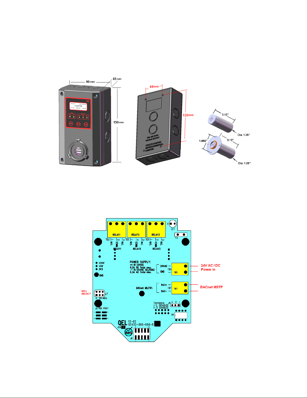
The enclosure is a NEMA 4 rated enclosure and can be wall mounted with 4 screws. To
maintain the NEMA rating, it is important that the conduit opening is sealed upon
installation.
2.2 Terminals
B5 Terminals
85950-101-000 RB August 7, 2015
Page 8

B5 Operation And Maintenance Manual
7
2.2.1 Wire and Cable
Terminal blocks TB1 to TB7 accept 12 AWG to 24 AWG wire. Use 16 AWG or 18
AWG wire for the power supply in long wiring runs, which can be up to 1km (1,000
meters) long.
We recommend using BELDEN 9841 for communications. This wire has 120 ohm input
impendence, which will eliminate RS-485 communication problems.
2.2.2 RS-485 Terminator
The terminator on each end of the RS485 run is designed to match the electrical
impedance characteristic of the twisted pair wire, and will prevent signal echoes from
corrupting the data on the line. The terminator should be enabled on BOTH ends of the
RS485 run. Short and medium length ModBus/485 runs can operate without the
terminating resistor. Longer runs may require the terminating resistors. But adding
terminator dramatically increases power consumption.
Factory default setting is disabled terminator.
The B5 supplies this resistor on the main board, and it is chosen using a jumper at J4.
• J4 1-2: Terminator Disabled / OFF (default)
• J4 2-3: Terminator Enabled / ON
2.2.3 RS-485 Driver Replacement
RS-485 lines in heavy industrial environments are sometimes subjected to magnetic
disturbances causing sufficient inducted power surges to damage the driver integrated
circuit (IC). This IC (U6) has a socket on the circuit card for ease of replacement in the
field.
2.2.4 Relays Output
The B5 has three onboard programmable Single-Pole Double-Throw (SPDT) relays.
These relays can be used to control other equipment, such as fans, lights, horns, etc.
eliminating the need for a separate controller.
Three terminal blocks (TB1, TB2 and TB3) are located on the main board. Each relay can
be programmed individually.
Switching capability of each relay is:
• 1.0 A maximum resistive load at 30 VDC
• 0.3A maximum resistive load at 125VAC
85950-101-000 RB August 7, 2015
Page 9

B5 Operation And Maintenance Manual
8
2.2.5 Note for B5:
The B5 supports BACnet MS/TP protocol and can be networked to form a BACnet
MS/TP network.
The B5 default baud rate is 38400bps.
Each B5 on the MS/TP network must have a unique BACnet MAC address and unique
Device Instance Number (Object ID).
• B5 valid MAC addresses are 0-127 for master node, 0-254 for slave node.
• B5 default MAC address is 126.
• Default Device Instance Number (Object ID) is 4005.
The B5 power supply and RS-485 connection are similar to the Q5. The B5 doesn't have
terminal blocks TB4 and TB6.
Avoid running communication wires or sensor input wires next to AC power wires or the
relay output wires. These can be sources of noise that can affect signal quality.
The B5 has a half wave rectifier on board. You will damage devices if you mix half
wave and full wave rectifiers on the same AC source. Use extreme caution when
sharing a common AC source. Sharing a common DC source is less problematic.
When the B5 input power is AC, the 24VAC can be either grounded or non-grounded.
Polarization is very important when the B5 is connected to a network. Make sure the
Neutral is connected to the GND of TB5.
2.2.6 Certification:
The Q5/B5 series have been certified to the following Standard:
Safety requirement for Electrical Equipment for Measurement, Control, and Laboratory UsePart 1: General Requirements CAN/CSA-22.2 No. 61010-1 Third Edition, Dated May 11, 2012;
And
Safety Requirements for Electrical Equipment for measurement, Control, and Laboratory UsePart 1: General Requirements UL 61010-1 Third Edition, Dated May 11, 2012.
Installation must be in accordance with ANSI/NFPA 70, National Electrical Code (NEC);
the
Canadian Electrical Code (CEC), Part I, CSA C22.1, and CSA C22.2 No. 0; and the
Manufacturers’ installation instructions
The Q5/B5 series have not been tested for Life Safety Applications and are not to be used in
Life Safety Applications in jurisdictions that require this certification
.
85950-101-000 RB August 7, 2015
Page 10
B5 Operation And Maintenance Manual
9
3. Function and Configuration
3.1 Indicators
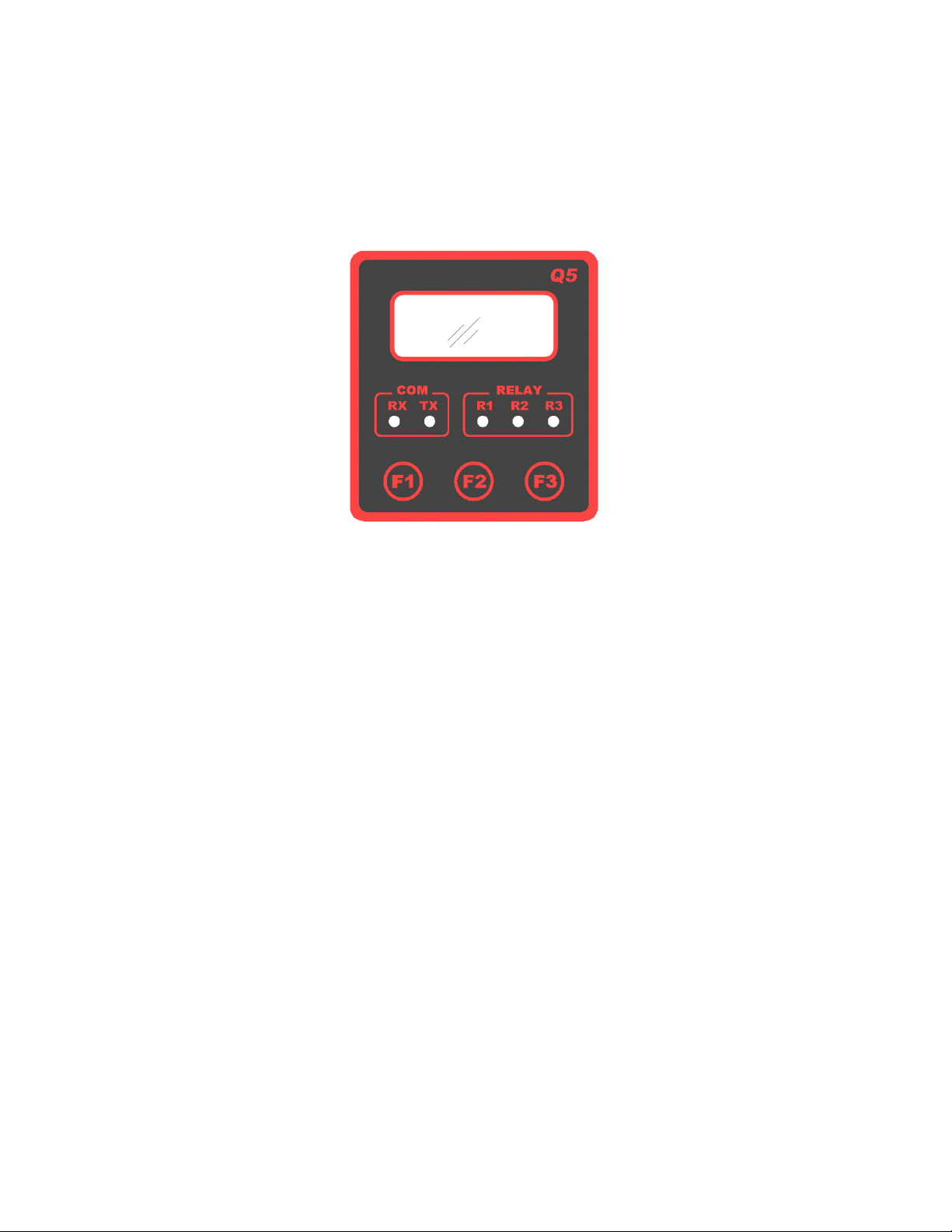
The indicators consist of five LED’s – two to indicate RS-485 digital communication,
three to indicate the status of relays 1-3.
3.1.1 RS485-TX/RX:
When the B5 is connected to a controller system via RS-485, the traffic of the
communication can be monitored visually through the two RS-485 indicators. One is RX
LED, which indicates the data stream received in from the controller. The other is TX
LED, which indicates the data stream out of the B5.
Note: If the TX LED or the RX LED is always ON, is indicative of a communication
problem. See Troubleshooting for RS-485.
3.1.2 Relay 1-3 LED:
Indicate the status of each relay. When the relay is actuated/closed, the relay LED is ON.
When the relay is de-actuated/open, the relay LED is OFF.
Note: If you set the relay to be Normally Energized (Fail Safe), the relay LED will
turn ON at non-alarm state and turn OFF at alarm state, because the LED reflects
the relay coil status.
85950-101-000 RB August 7, 2015
Page 11
B5 Operation And Maintenance Manual
10
3.2 Tool Function
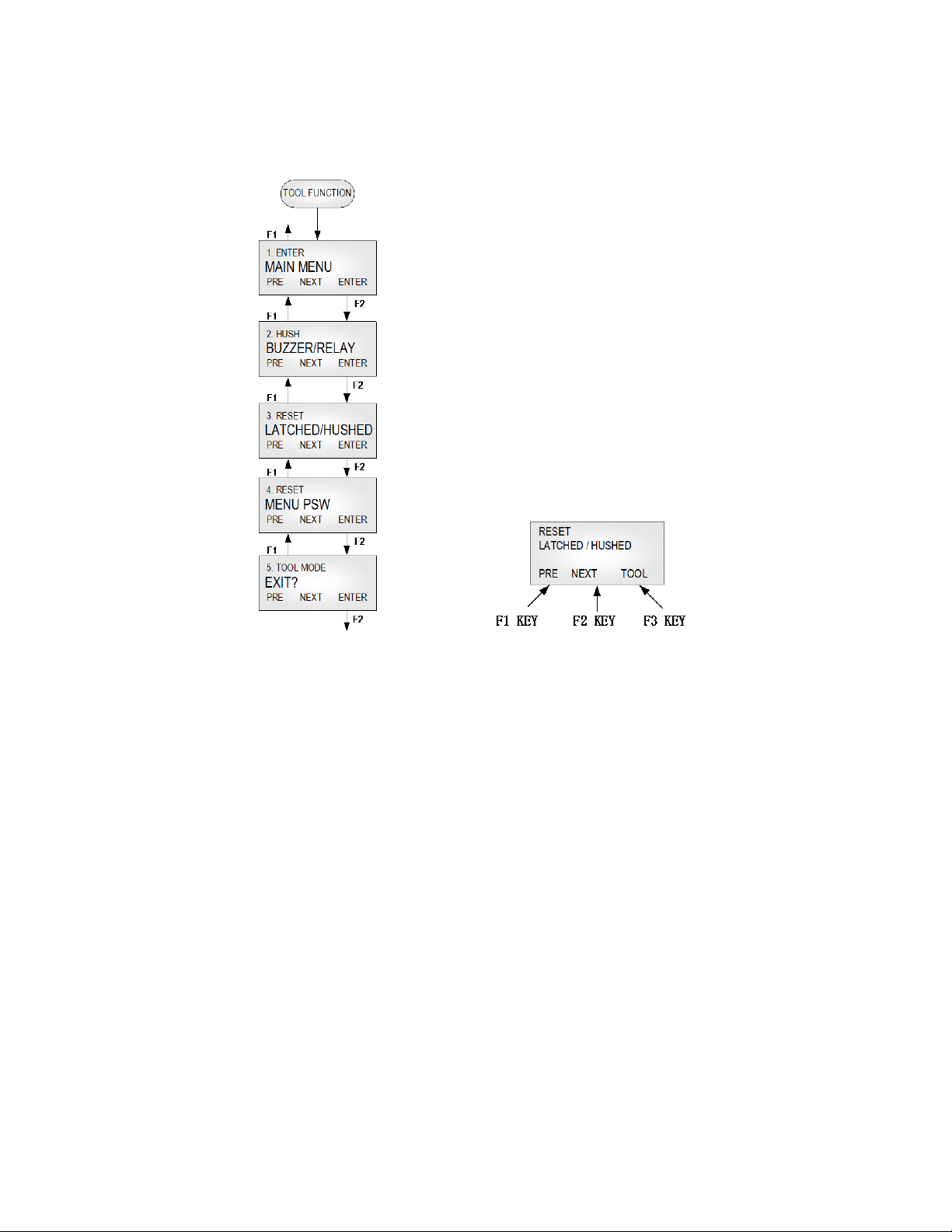
Press key [F3] to enter tool functions that might be used frequently in the field.
3.2.1 Enter Main Menu
Press key [F1] to browse previous item of the current menu.
Press key [F2] to browse next item of the current menu.
Press key [F3] to enter the main menu for more configuration and settings.
3.2.2 Hush Buzzer and Relay
Press key [F3] to silence the buzzer and buzzer-style relays.
3.2.3 Reset Latched/Hushed
To acknowledge a latched condition or a hushed condition, press key [F3] to reset latched
relays and hushed buzzer for which the alarm condition has been removed. If the alarm
condition (e.g. high gas concentration) is still present the relay(s) will not reset.
3.2.4 Reset MENU Password
If you forgot the main menu password, you can reset the menu password to default
password “4321” by entering a correct active code. For the active code, contact ACI.
3.2.5 Exit Tool Mode
Press key [F3] to return to monitoring mode.
85950-101-000 RB August 7, 2015
Page 12
B5 Operation And Maintenance Manual
11
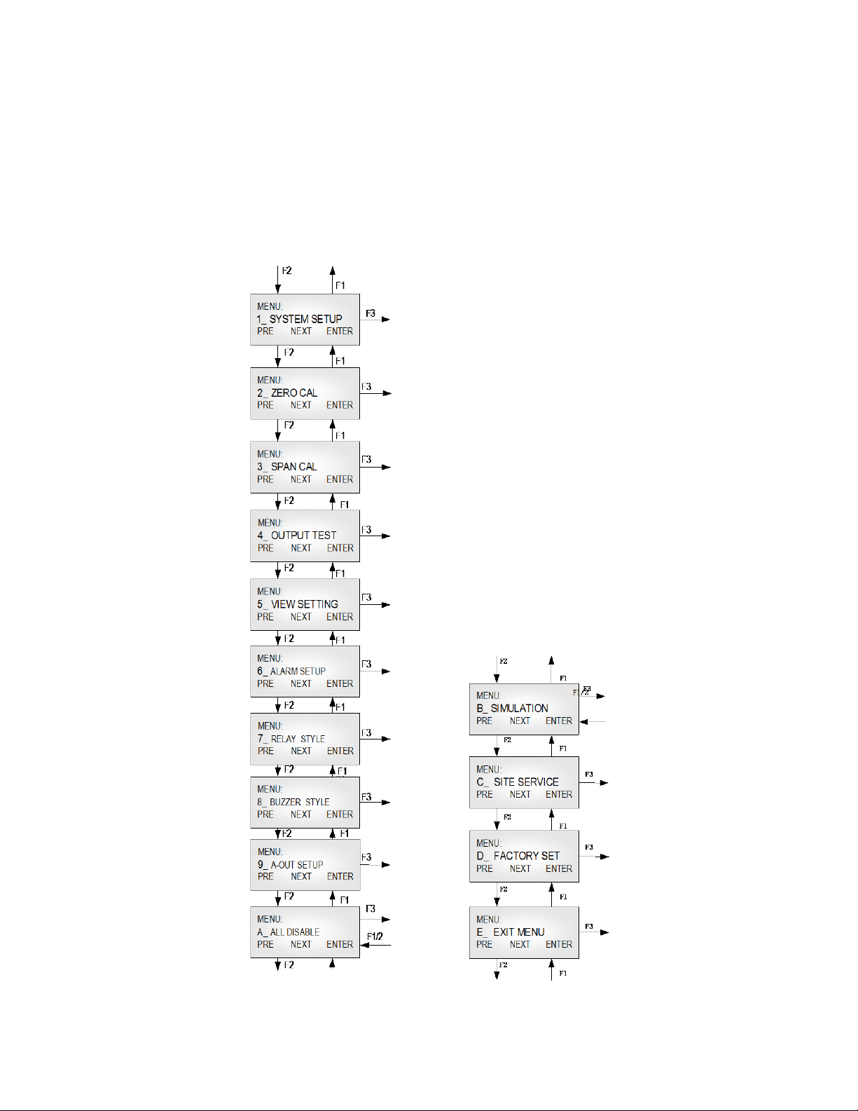
3.3 Main Menu Tree
The main menu is password protected. Once the password is accepted, you are allowed
into the main menu tree.
Factory default password is 4321.
Note: While in the menu tree, all normal monitoring operations stop. The alarm
status does not change.
85950-101-000 RB August 7, 2015
Page 13

B5 Operation And Maintenance Manual
12
the sensor and relay status information scrolls
automatically. Set the number of seconds for each item to be displayed.
ts the execution of the TimeSynchronization service and
780 to +780) offset between local standard time and Universal Time
It indicates whether daylight saving time is in effect (Enabled) or not
supports BACnet MS/TP master or slave protocol. Default is
3.4 Menu “1_SYSTEM SETUP”
The system setup subdivision contains general settings for monitor operations,
communications and 4-20mA calibrations.
3.4.1 System Settings
Password: Default password is 4321.
MAC
The B5 RS-485 address can be defined from 0 to 255. B5 default address is
126.
Address:
Object ID: BACnet Device Instance Number. Default is 4005.
Baud rate: Define baud rate for RS-485 communication with BACnet protocol.
B5 default baud rate is 38400 bps.
Scroll Rate: In normal operation,
Default value is 3 seconds.
Backlight: The LCD backlight can be set to Always Off, Always On and Auto Power
Saving mode. In Auto Power Saving mode, the backlight will turn on for 10
seconds after any key has been pressed. Default setting is Always ON.
UTC Offset The B5 suppor
UTCTimeSynchronization service. It indicates the number of minutes ( -
Coordinated. Default is +300 (US & Canada Eastern Time).
Daylight
Saving
New
Password:
(Disabled) at the B5 location in UTCTimeSynchronization service.
Default is Enabled.
The new password can be any combination of up to four digits. Default
password is 4321.
Warning: Be sure that you record the new password in a safe and
secure location!
Protocol: The B5
MS/TP master.
85950-101-000 RB August 7, 2015
Page 14

B5 Operation And Maintenance Manual
13
its own zero and work off the last manual or factory calibration. Default
and precision
Display
Mode:
• Display Instant: displays instantaneous gas concentration
• Display Average:
o Displays STEL (15min average reading)
o Displays TWA (8 hour average reading)
o Displays daily peak
• Display Alarm: displays alarm 1-8 status
• Display Relay: displays relay 1-3 status
• Display Buzzer: displays buzzer 1-3 status
• Display A-Out mA: displays current 4-20mA output
• Display A-Out VDC: displays current VDC output
• Display Clock: displays real time clock
If there is nothing to display, the unit will display “Running…”
Auto Zero: When AutoZero is set to ON, the unit will gather the lowest reading in 7-
day period and set the unit into Zeroing Calibration mode so that the lowest
reading goes to zero. When AutoZero is set to OFF, the unit will not adjust
Key
Beeper:
Restore
Default:
value is OFF.
NOTE: AutoZero works best in situations where the building will purge
at night (or over a weekend) to a zero concentration of target gas.
ON: Beeping when keypad is touched
OFF: No beeping when keypad is touched
Note: Don’t do this if you don’t have calibration gas
reference instrumentation to calibrate the unit.
To load defaults to factory settings, to restore the unit to correct operation.
The settings below will be restored to default values:
-Password, -Baud rate, -Scroll rate, -Backlight, -Display mode, -Key beeper,
-LCD contrast, -Gas type on the Sensor Board, -Alarm settings, Relay/Buzzer settings, and 4-20mA/1-5VDC settings.
The unit needs to change the gas type if the sensor on the sensor board is not
the default gas type: CO, CH4 or O2. Contact ACI for instructions.
Zero and span calibrations are needed.
85950-101-000 RB August 7, 2015
Page 15

B5 Operation And Maintenance Manual
14
B5 supports the execution of the TimeSynchronization service and
the more critical the nature of the output.
Priority #16 is the lowest
ADJ Clock: Adjust real time clock.
The
UTCTimeSynchronization service. The clock can be adjusted remotely.
ADJ
Contrast:
Check
Battery
Output
Priority:
Adjust the LCD contrast. Valid values are between 10 (light) and 50 (dark).
Default is 21.
The sensor board is equipped with a coin battery. This setting will enable or
disable the B5 to check the battery voltage and beep for a low battery level.
Default is ON.
Alarm output (BV) present_value and relay output (BO) present_value
support command prioritization. The B5 has priority #12 as default.
The lower the priority umber
Priority #1 is considered the highest priority.
priority.
85950-101-000 RB August 7, 2015
Page 16

B5 Operation And Maintenance Manual
15
2_ ZERO CAL
CONTINUE?
XXPPM
3.5 Menu “2_ZERO CAL”
The B5 is calibrated using a two-point calibration process. First, use a “Zero Gas”, then
use a “CAL Gas” containing a known concentration of a standard reference gas, to set the
second point of reference.
3.5.1 Equipment Required
• A cylinder of Zero Gas, (clean air or nitrogen).
• A cylinder of Cal Gas
• Flow Limiting Regulator(s) 0.2 to 1.0 lpm
• Tubing
3.5.2 Zeroing Calibration Procedure
• “2_ ZERO CAL:”
• Press key [F3] and the device will show the calibration notice and then ask if you
want to continue. The middle line will display the current concentration.
• Apply the Zero Gas.
• Wait for about 3 minutes or until the reading is stable.
• Press key [F3] to confirm Zeroing Cal.
• When the device is in Zeroing CAL, it will take 3 seconds to 20 seconds to
complete.
• When the zeroing CAL operation is over, the device will display “Accepted” and
return to “2_ZERO CAL”.
• Make sure there is no Cal Error displayed. If Cal Error is reported, repeat the
procedures above. If the Cal Error is still showed up, the sensor may be expired.
• Remove the gas.
• Exit the menu to Monitoring Mode.
85950-101-000 RB August 7, 2015
Page 17

B5 Operation And Maintenance Manual
16
3_ SPAN CAL
CAL GAS:
> XXX
CONTINUE?
XXPPM
3.6 Menu “3_SPAN CAL”
• “3_ SPAN CAL”
• Press key [F3] and the device will ask for the CAL GAS, input the concentration
of the calibration gas.
• Press key [F3] and the device will show the calibration notice and then show the
flow rate for the span calibration. Press any key to continue, and then the device
will ask you if you want to continue. The middle line will display the current
concentration.
• Apply the calibration gas.
• Wait for about 3 minutes or until the reading is stable.
• Press key [F3] to confirm SPAN CAL.
• When the device is in span cal, it will take 10 seconds to 1 minute to complete.
• When the span cal operation is over, the device will display “Accepted” and
return to “3_SPAN CAL”.
• Make sure there is no Cal Error displayed. If Cal Error is reported, repeat the
procedures above. If the Cal Error is still showed up, the sensor maybe expired.
• Remove the gas.
• Exit menu to Monitoring Mode.
85950-101-000 RB August 7, 2015
Page 18
B5 Operation And Maintenance Manual
17
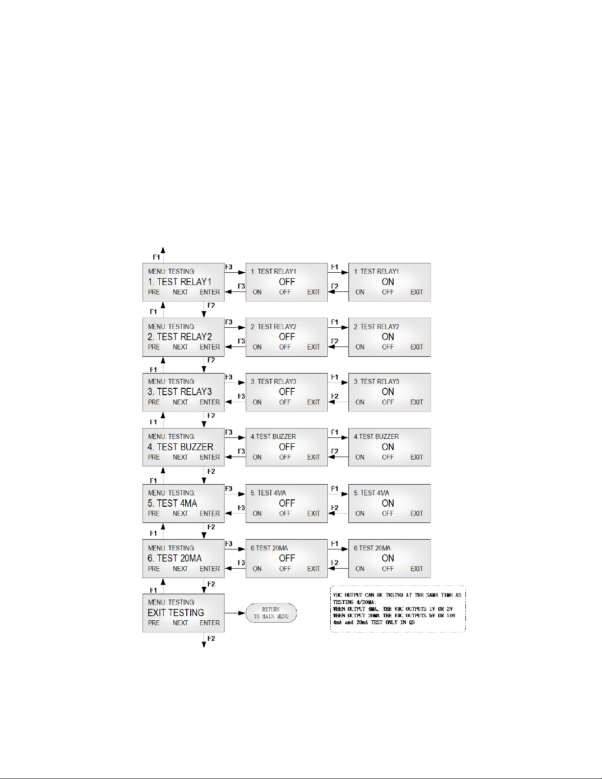
3.7 Menu “4_OUT TEST”
During system installation and testing, it may be necessary to force relays and buzzers on
and off.
The Relay Testing feature allows the user to force the actuation of each relay. This
function forces an Actuate vs. De-actuate action, not an energized vs. non-energized
action. Therefore the user must be aware of these relays, which have been defined as
normally energized or not normally energized.
The 4mA (1VDC/2VDC) and 20mA (5VDC/10VDC) outputs can be tested too.
85950-101-000 RB August 7, 2015
Page 19
B5 Operation And Maintenance Manual
18
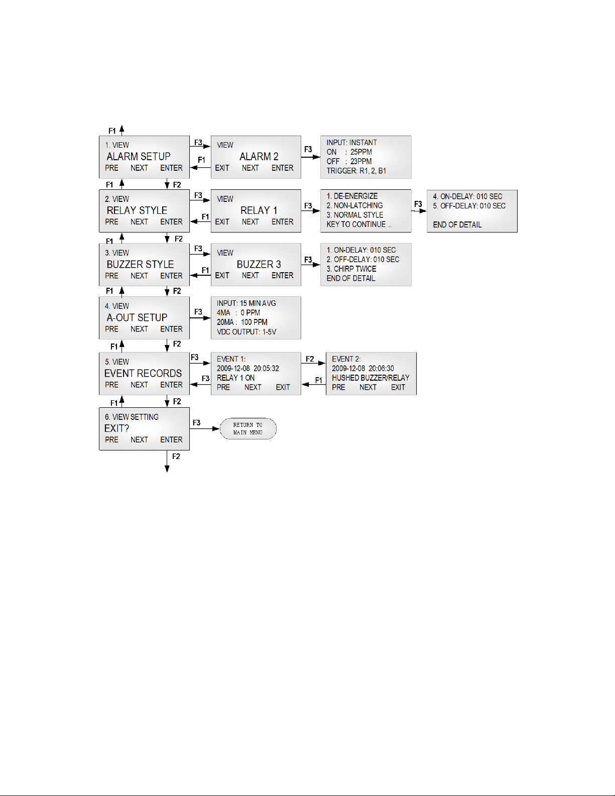
3.8 Menu “5_VIEW SETTING”
This function is to verify the settings for the alarms, relays, buzzers and analog outputs.
85950-101-000 RB August 7, 2015
Page 20

B5 Operation And Maintenance Manual
19
(STEL): Short Term Exposure Limit, average
no matter the gas
3.9 Menu “6_ALARM SETUP”
The B5 supports alarm 1 to alarm 8.
Alarm is a programmable condition that can receive a selectable input and trigger relays
and buzzers.
Disabled or
Each alarm may be individually set to be enabled or disabled. If the alarm
is disabled, the alarm will not be used to calculate or trigger anything.
Enabled:
Default: Alarm 1 to Alarm 4 is enabled. Alarm 5 to Alarm 8 is
disabled.
Input: One of five inputs is selected to calculate the alarm condition status to
trigger the selected outputs:
• INSTANT: instantaneous gas reading.
• 15 MIN AVG
reading over 15 minutes.
• 8 HOURS AVG (TWA): 8-hour Time Weighted Average, average
reading over 8 hours.
• DAILY PEAK: daily peak reading.
• FAULT: If the unit reports any faults,
concentration, it will trigger the selected outputs.
Alarm On
If Alarm On is greater than or equal to Alarm Off:
and
Alarm Off
Alarm On: Sets the concentration at or above which the relay will actuate.
Alarm Off: Sets the concentration at or below which the relay will deactuate.
Reading:
If Action On is less than Action Off:
Action On: Sets the concentration below that the relay will actuate.
Action Off: Sets the concentration above that the relay will de-actuate.
Trigger: Trigger Outputs: Relay 1, Relay 2, Relay 3, Buzzer 1, Buzzer 2, Buzzer 3
85950-101-000 RB August 7, 2015
Page 21

B5 Operation And Maintenance Manual
20
Each relay may be individually set to be enabled or disabled. If it’s
3.10 Menu “7_RELAY STYLE”
Enabled:
disabled, the relay will always de-actuate no matter what the current gas
concentration.
Default is Enabled.
Normally
Each relay may be individually set to be normally energized or normally
de-energized.
Deenergized:
Default is normally de-energized.
Latching: Each relay may be set to latch in actuate status until acknowledged by a
front-panel action.
Default is Non-Latching.
ON Delay:
“Delay on Actuation” or “Delay on Make”. For each relay a separate time
delay may be set from 0 to 990 seconds before an alarm condition will
cause the relay to actuate.
Default is 5 seconds.
OFF Delay: “Delay on De-Actuation” or “Delay on Break”. For each relay a separate
time delay may be set from 0 to 990 seconds before a return to a nonalarming signal condition will cause the relay to de-actuate.
Default is 5 seconds.
Style: Normal Relay Style: Work as normal relay.
Buzzer Style Relay: When the relay is used to control a buzzer or horn.
Working as a buzzer style will make the relay have the same function as
the buzzer. It will be switched off when performing the Hush
Buzzer/Relay function in the Tool Menu.
Default is OFF.
85950-101-000 RB August 7, 2015
Page 22

B5 Operation And Maintenance Manual
21
3.11 Menu “8_BUZZER STYLE”
The buzzer style is almost identical to that of the relays, except the style that represents
the buzzer tone options:
• Tone 1: Chirp once.
• Tone 2: Chirp twice.
• Tone 3: Intermittent 50% duty cycle.
• Tone 4: Continuous.
The menus are identical to those for the Relay Style.
3.12 Menu “A_ALL DISABLE”
This function is for calibration, system testing etc. When All Disable is ON, the status of
the relay, buzzer and analog output, etc., will freeze in their current state.
Default is OFF.
3.13 Menu “B_SIMULATION”
Simulation mode is used to assist in testing the installation before commissioning. When
simulation is enabled, the unit will not detect gas concentrations; it will display the
simulated value and use it to calculate the status of relays and buzzers. This feature is
available for evaluating the user settings and testing the installation (e.g.: the activation of
the valve, fan speed, relay set points, etc. can be verified.)
Any concentration between 0ppm and 9999ppm can be simulated.
3.14 Menu “C_SITE SERVICE” and “D_FACTROY SET”
Factory service staff access only. The customer has no need to operate it.
4. BACnet PIC Statement Supported By B5
See document: 85950-103-000 (B5 PIC Statement).
4.1 Smart Sensor Assembly Replacement
4.1.1 Disassembling
Observe all safety and electrical codes and regulations before removing enclosure lid.
85950-101-000 RB August 7, 2015
Page 23
B5 Operation And Maintenance Manual
22
Important: Calibrate the transmitter whenever a component is replaced. But if you replace
a smart sensor assembly with a sensor onboard from ACI, you don’t need to recalibrate
the transmitter, as all the calibration information has been stored in the smart sensor
board in the factory process.
4.1.2 Replacement Procedure
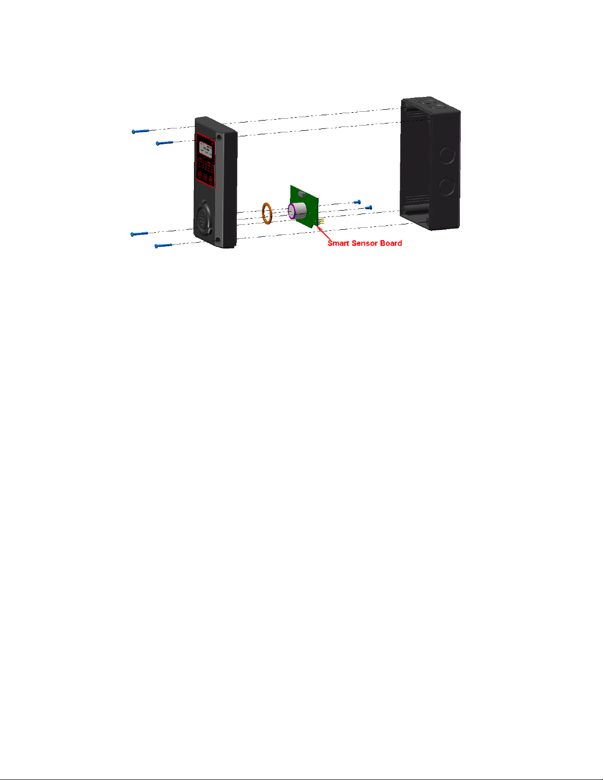
To replace the entire smart sensor assembly, complete the following steps:
1. Power down the transmitter.
2. Remove the four screws securing the enclosure lid assembly to the base enclosure
and remove the enclosure lid assembly.
3. Remove the two screws securing the smart sensor board and remove the smart
sensor board from the lid assembly
4. Feed the O-ring over the sensor on the new smart sensor assembly
5. Plug the new smart sensor assembly and secure with two screws. Ensure that the
connectors are correctly matched. Incorrect installation may damage the sensor
assembly and/or the display board.
85950-101-000 RB August 7, 2015
Page 24

23
4.1.3 Replacement Parts
Code
Gas
Symbol
Span
Smart Sensor Assembly
0
Oxygen
O2
0 - 25%VOL
85930-016-000
16
Methane
CH4
0 - 100%LEL
85930-017-016
17
Propane
C3H8
0 - 100%LEL
85930-017-017
18
Hydrogen
H2
0 - 100%LEL
85930-017-018
*19
Combustible
LEL
0 - 100%LEL
85930-017-019
*20
Ethylene
C2H4
0 - 100%LEL
85930-017-020
*21
Iso-Butane
C4H10
0 - 100%LEL
85930-017-021
*22
Iso-Pentane
C5H12
0 - 100%LEL
85930-017-022
*23
Methanol
CH3OH
0 - 100%LEL
85930-017-023
*24
Benzene
C6H6
0 - 100%LEL
85930-017-024
*25
Acetone
CH3CO
0 - 100%LEL
85930-017-025
*26
Butanol, n-Butane
BUTAN
0 - 100%LEL
85930-017-026
1
Carbon Monoxide
CO
0 – 250ppm
85930-018-001
1
Carbon Monoxide
CO
0 – 1000ppm
85930-018-201
2
Hydrogen Sulfide
H2S
0 – 25ppm
85930-018-002
2
Hydrogen Sulfide
H2S
0 – 100ppm
85930-018-202
3
Sulphur Dioxide
SO2
0 – 6ppm
85930-018-003
5
Nitrogen Dioxide
NO2
0 – 10ppm
85930-018-005
6
Hydrogen
H2
0 – 1000ppm
85930-018-006
6
Hydrogen
H2
0 – 2000ppm
85930-018-206
7
Hydrogen Cyanide
HCN
0 – 50ppm
85930-018-007
9
Ammonia
NH3
0 – 100ppm
85930-018-009
9
Ammonia
NH3
0 – 1000ppm
85930-018-209
11
Ozone
O3
0 – 1ppm
85930-018-011
13
Chlorine
Cl2
0 – 5ppm
85930-018-013
14
Chlorine Dioxide
ClO2
0 – 2ppm
85930-018-014
96
Arsine
AsH3
0 – 1ppm
85930-018-096
97
Phosphine
PH3
0 – 5ppm
85930-018-097
97
Phosphine
PH3
0 – 1ppm
85930-018-297
98
Silane
SiH4
0 – 50ppm
85930-018-098
99
Germane
GeH4
0 – 2ppm
85930-018-099
100
Diborane
B2H6
0 – 2ppm
85930-018-100
B5 Operation And Maintenance Manual
Code
Code
Gas Symbol
Gas Symbol
Span Smart Sensor Assembly
Span
Smart Sensor Assembly
85950-101-000 RB August 7, 2015
Page 25

B5 Operation And Maintenance Manual
24
4
Nitric Oxide
NO
0 –100ppm
85930-018-004
8
Hydrogen Chloride
HCl
0 – 30ppm
85930-018-008
12
Ethylene Oxide
ETO
0 – 20ppm
85930-018-012
Hydrogen
Bromide
15
Carbon Dioxide
IR-CO2
0 –5000ppm
85930-019-015
15
Carbon Dioxide
IR-CO2
0 – 5%VOL
85930-019-215
15
Carbon Dioxide
IR-CO2
0 – 20%VOL
85930-019-315
15
Carbon Dioxide
IR-CO2
0 – 100%VOL
85930-019-415
16
Methane
IR-CH4
0 – 100%LEL
85930-019-016
16
Methane
IR-CH4
0 – 100%VOL
85930-019-216
Code
101
Code
Gas Symbol
HBr 0 – 30ppm 85930-018-101
Gas Symbol
Span
Span
Smart Sensor Assembly
Smart Sensor Assembly
85950-101-000 RB August 7, 2015
Page 26
25
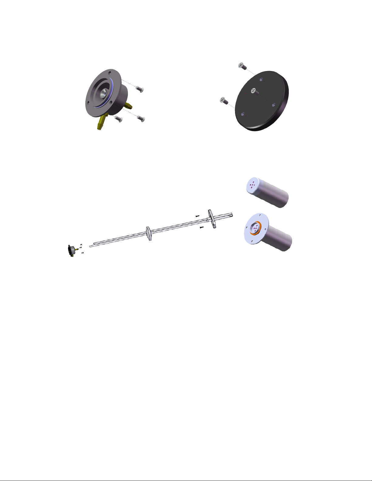
4.1.4 Accessories
Pump-thru & Splash Guard Kit
Calibration Cap Kit
SKU#: 85930-006-000 SKU#: 85930-007-000
B5 Operation And Maintenance Manual
Duct Mount Adapter Kit Free stand or Duct mount IR-Probe
SKU#: 85930-040-000
85950-101-000 RB August 7, 2015
Page 27

B5 Operation And Maintenance Manual
26
SYMPTOMS
PROBABLE CAUSE
SUGGESTED SOLUTION
RS-485
• RS-485 bus connection has a
• Disconnect the cable to isolate
No response to gas
• Sensor screen is dirty
• Clean sensor opening
Apparent false alarm
• Puff of gas
• Monitor is functioning
5. Troubleshooting
This troubleshooting guide is intended as an aid in identifying the cause of unexpected
behavior and determining whether the behavior is due to normal operation or an internal
or external problem.
RX LED or
TX LED constantly ON
problem
• RS-485 driver U6 is damaged
• Controller side RS-485 driver
has problem
• Sensor has expired
• Not properly calibrated
• Solvent fumes or interference
from high levels of interfering
gas
• Radio frequency interference
the problem
• Replace U6 IC on main board
• Replace the RS-485 driver on
the controller
• Replace smart sensor assembly,
see Replacement Parts
• Recalibrate
• Remove source of interfering
gas
• Check that grounding and
shielding is correct
85950-101-000 RB August 7, 2015
Page 28

B5 Operation And Maintenance Manual
27
WARRANTY STATEMENT
All ACI equipment is warranted against defects in material and workmanship for a period of two
years from date of shipment with the following exceptions:
Electrochemical Sensors (Toxic) Six Months
Catalytic Sensors (Combustible) One Year
Full warranty information can be found on ACI’s website:
http://www.workaci.com/sites/default/files/warranty.pdf
LIMITED LIABILITY
All ACI systems shall be installed by a qualified technician/electrician and maintained in strict
accordance with data provided for individual systems in the form of installation/maintenance
manuals. ACI assumes no responsibility for improper installation, maintenance, etc., and stresses
the importance of reading all manuals. ACI shall not be responsible for any liability arising from
auxiliary interfaced equipment nor any damage resulting from the installation or operation of this
equipment.
ACI’s total liability is contained as above with no other liability expressed or implied as the
purchaser is entirely responsible for installation and maintenance of systems.
This warranty is in lieu of all other warranties, expressed or implied, and no representative or
person is authorized to represent or assume for ACI any liability in connection with the sales of
our products other than that set forth herein.
NOTE: Due to on-going product development, ACI reserves the right to change
specifications without notice and will assume no responsibility for any costs as a
result of modifications.
For further information or assistance, contact:
AUTOMATION COMPONENTS, INC.
2305 Pleasant View Road
Middleton, Wisconsin
Tel: (888) 967-5224
Fax: (608) 831-7407
Web: workaci.com
85950-101-000 RB August 7, 2015
 Loading...