

Page 1

Installation and Operating Handbook
ANALOGUE
Autohelm 1000
Page 2

Page 3

The Autohelm 1000 is a highly developed autopilot
built to operate reliably in exposed marine
conditions. When correctly installed it will soon
ears of
The system has been designed for owner installation
and aided by the following installation guide,
fitting should prove to be a straightforward and
Cockpit and tiller configurations vary widely, and
me cases special attachments may be
necessary to effect the neatest possible
installation. The attachments available and their
applications are fully described and are stocked
are
encouraged to contact our Technical Sales
become a vital crew-member giving many y
invaluable service.
enjoyable job.
thus in so
for immediate supply when required.
In cases where special advice is needed you
Department who will be pleased to assist.
Page 4

INSTALLATION
Page 5
The basic actuator unit is a totally self-
contained
magnetic sensing automatic pilot. The autopilot is
ttachment
point to the yacht's structure. After connection to
the yacht's 12 volt electrical system the unit
Since the autopilot incorporates a magnetic sensing
device, it is advisable to ensure that the yacht's
ituated at least 2'6” (750mm)
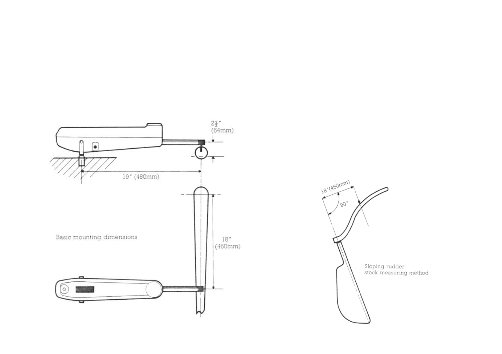
The actuator pushrod attaches to the tiller via a
ended pin situated 18” (460mm) radially
distant from the rudder stock or rudder pintle
osition
ended pin must be positioned at a
radius of l8” (460mm) at 90 degrees to the axis of
rudder rotation as shown on the accompanying
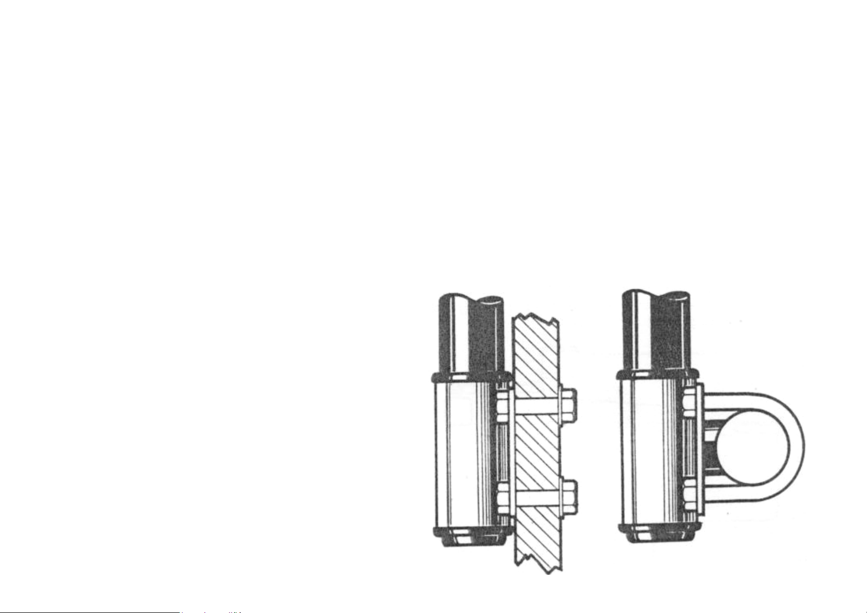
The autopilot slots into the bronze mounting socket
y fixed in
position. The mounting socket should be positioned
of the cockpit centreline
to ensure that port and starboard tiller movements
are equalised. It is also important to ensure that
possible to 90 degrees to the tiller when the
mounted between the tiller and a single a
becomes operational.
steering compass is s
away to avoid deviation.
ball-
centreline.
If the rudder pivot axis is sloping, the p
of the ball-
illustration.
A provided, which should be permanantl
19” (480mm) to starboard
the unit is positioned horizontally and as near as
tiller is centralised.
4
Page 6
Porthand mounting
In certain instances it may be more convenient to
mount the unit on the porthand side. The standard
the tiller and where porthand mounting is required
Porthand systems must be fitted with porthand wind
When the tiller is positioned low in the cockpit
able in height, the mounting socket
can be most conveniently positioned on the
starboard cockpit seat. The pushrod is attached to
the tiller via the standard ballpin provided which
is inserted directly into the top of the tiller.
(6mm) drilled hole and securing with a good quality
two pack epoxy adhesive such as Araldite. The
shoulder of the ballpin should be positioned ½”
(12.5mm) above the upper surface of the tiller to
The autopilot mounting socket is installed by
inserting it into a 1.2” (12.5mm) drilled hole and
permanently bonded with Araldite. It is important
to ensure that the mounting socket is securely
,
consists only of a single glass fibre skin of less
thickness than the depth of the socket it will be
necessary to provide reinforcement by bonding a
The autopilot is capable of generating very high
loads and it must be stressed that in all
cases the mounting socket should be very firmly
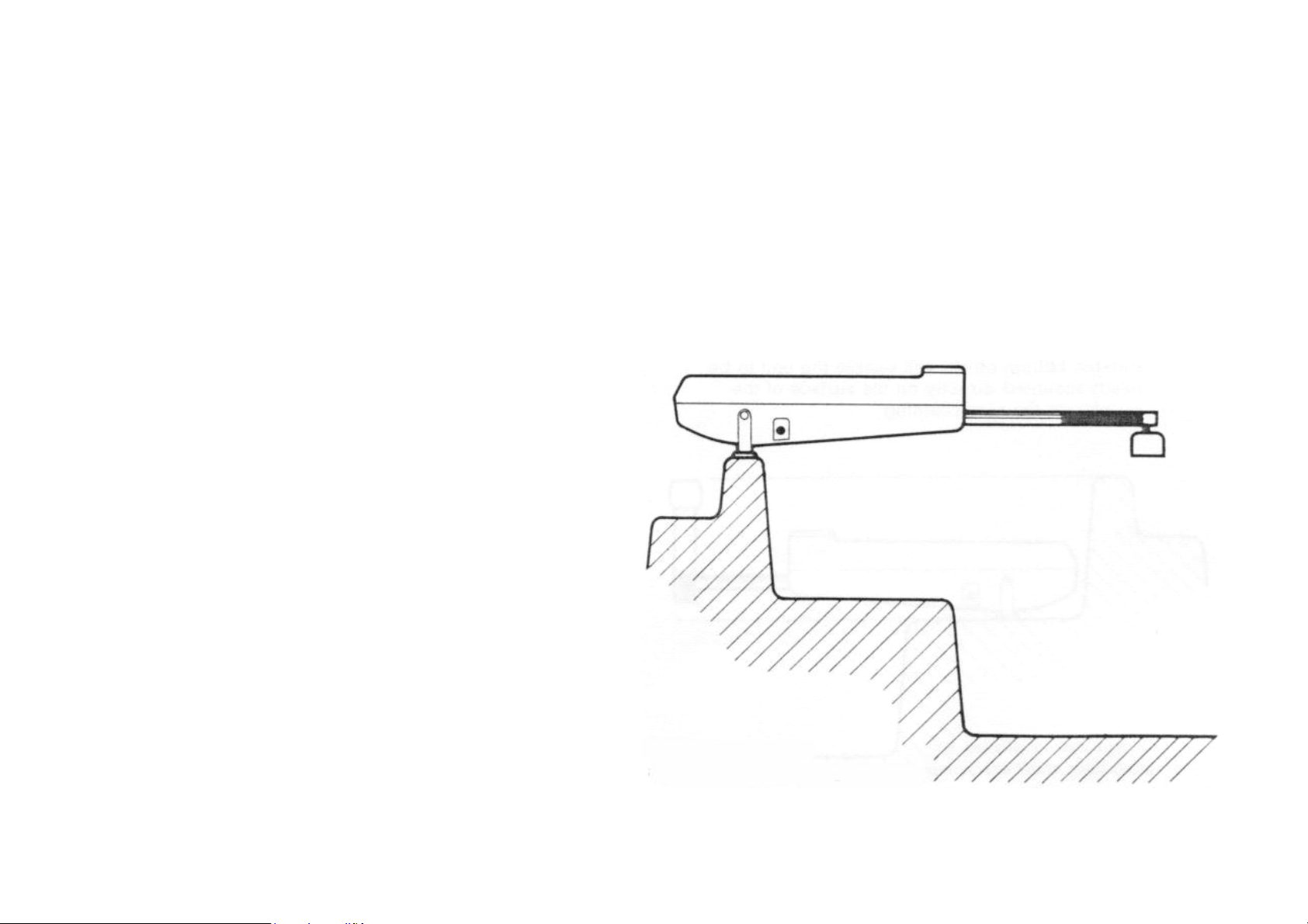
In some cases it may not be possible to provide a
convenient site for the mounting socket at the
of 19" (480mm). In such
cases the mounting distance can be increased in
increments of 1" (25mm) to a maximum of 6" (l5Omm)
with the use of special pushrod extensions. The
pushrod is extended by first unscrewing the pushrod
hrod extension
into position between the pushrod and the end cap.
This attachment is necessary, for example. When the
cockpit is unusually wide or when it is convenient
Extended pushrods
unit is sensed to operate on the starboard side of
a special porthand system must be ordered.
vane attachments.
Basic installation method
and is adjust
The ballpin is installed by inserting it into a ¼”
avoid fouling when the pushrod is fully retracted.
standard mounting distance
end cap and then screwing the pus
to mount the unit on the cockpit coaming.
installed. If the mounting site, for example
plywood strengthening plate to the underside.
pushrod
bonded into position.
Page 7

5
Page 8

Tiller attachments
er is not adjustable in height or is
positioned appreciably higher than the most
convenient site for the mounting socket. It is
often convenient to lower the ballpin underneath
the tiller. Standard tiller cranks are available in
he ballpin centre in
increments of 1” (25mm) to a maximum of 5” (125mm)
below the underside of the tiller. Since the
pushrod centreline is positioned 2” (62mm) above
the mounting socket, these attachments can cater
ing socket
and the underside of the tiller of up to a maximum
of 7" (190mm). This attachment is particularly
in the case of transom hung rudder
configurations (such as the Folkboat) where the
tiller passes over an extended counter. In such
set
will enable the unit to be neatly mounted directly
The tiller crank attachments are bolted through the
centreline of the tiller, with ¼” (6mm) diameter
nce the bolts through the neutral
bending axis, the bending strength of the tiller
will not be significantly altered. The securing
bolts should be looked into the clearance holes
through the tiller with epoxy adhesive to ensure
When the till
a range of sizes to lower t
for a vertical distance between the mount
useful-
cases a tiller crank of suitable ballpin off-
on the surface of the counter or the rear coaming.
bolts and si
that they do not work loose in operation.
Page 9

6
Page 10

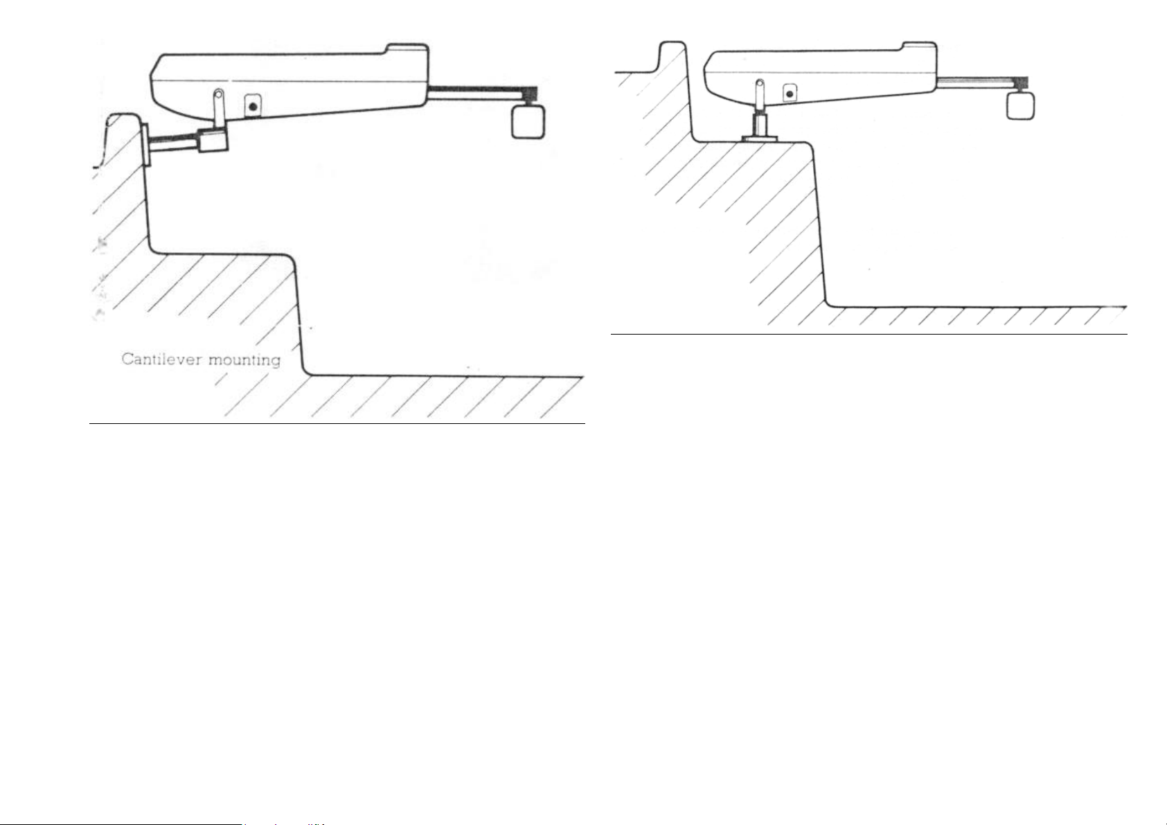
Cantilever mounting
It may sometimes be necessary to attach the
autopilot to a vertical face such as the cockpit
sidewall. In this case, a special cantilever
mounting is available and is particularly
itioned
substantially higher than the level of the cockpit
seat. Full instructions are supplied with each
cantilever mounting kit. The standard cantilever
mounting kit allows the autopilot mounting socket
set by a maximum of 10” (250mm) from the
vertical mounting face. This maximum dimension may
be reduced by cutting the cantilever to length
during installation. The cantilever screws into a
permanently mounted base which is bolted into
position by three ¼” (6mm) stainless steel bolts.
er may be unscrewed from its permanent
mounting base to allow unobstructed working space
In certain cases it may be convenient to raise the
height of the autopilot mounting socket above the
or counter for example. Standard
pedestal assemblies are available to raise the
mounting height from 1½” to 3½" above the mounting
surface in ½" (12.5mm) increments. The pedestal
base is bolted into position by three ¼” (6mm)
he autopilot is not in
use the pedestal may be unscrewed from its base to
convenient when the tiller is pos
Pedestal mounting
cockpit seat
stainless steel bolts. When t
to be off-
The cantilev
when the autopilot is not in use.
allow clear working space when necessary.
Page 11
7
Page 12
The wind vane attachment consists of two basic
the mounting mast which elevates the wind
vane into clear wind and the wind vane transducer
ttaches to the clevis at the head of
the mast by means of the cranked key provided. The
wind vane transducer is electrically connected to
the main autopilot unit by means of the waterproof
jack plug on the end of the interconnecting cable.
ne is not in use and the waterproof
plug is disconnected special care mist be taken to
ensure that the rubber blanking plug attached to
the socket on the main autopilot unit is firmly
pushed into position. If this is not done water
ket and temporarily disable
In very many cases the autopilot can be installed
without the need for special attachments. Where
t easily possible the above standard
attachments will normally provide a neat solution
and avoid the need for structural alterations. In
very rare cases where the standard range of
attachments do not provide a convenient mounting
ssary to consider the use
of purpose made attachments. In the event of
difficulties occurring, our Technical Sales
For trial purposes the actuator power lead may be
's 12 volt battery.
terminal. If the power connections are accidentally
reversed the autopilot will not function but no
at a waterproof plug and socket
is situated adjacent to the unit and the power lead
shortened. A standard 5 amp fuse should be provided
in the power supply circuit to protect the internal
supply cable between the battery and the waterproof
NB The equipment must not be connected to a battery
Use of attachments
this is no
arrangement it may be nece
Department will be pleased to advise.
Wind vane attachment
modules –
head which a
When the wind va
Battery connection
connected directly to the vessel
The brown lead should be connected to the positive
terminal and the blue lead to the negative
damage will result.
It is recommended th
outlet socket.
charger for testing.
could enter the jack soc
the autopilot until the water is dried out.
Page 13

8
Page 14
Similarly when the jack plug is inserted in wet
cockpit conditions, extreme care should be taken to
ensure that the plug is kept dry. Occasional
with Vaseline will
help to minimise problems of water intrusion. Once
the jack plug has been inserted, the connection is
The wind vane transducer mounting mast is normally
clamped centrally to either a vertical or
f the after pulpit using the 'U'
clamps provided. In the event of an after pulpit
not being fitted the mounting flange may be bolted
directly to a suitable vertical face. Care must be
taken to ensure that the wind vane transducer is in
acks and not too close to the
deflected air stream from the mainsail. This is
normally ensured by situating the mounting mast
centrally behind the backstay and by elevating the
wind vane at least 2ft (60cm) above the highest
The autopilot operates on the principle of
mechanical feedback between the sensors and the
rudder to correlate corrective rudder action with
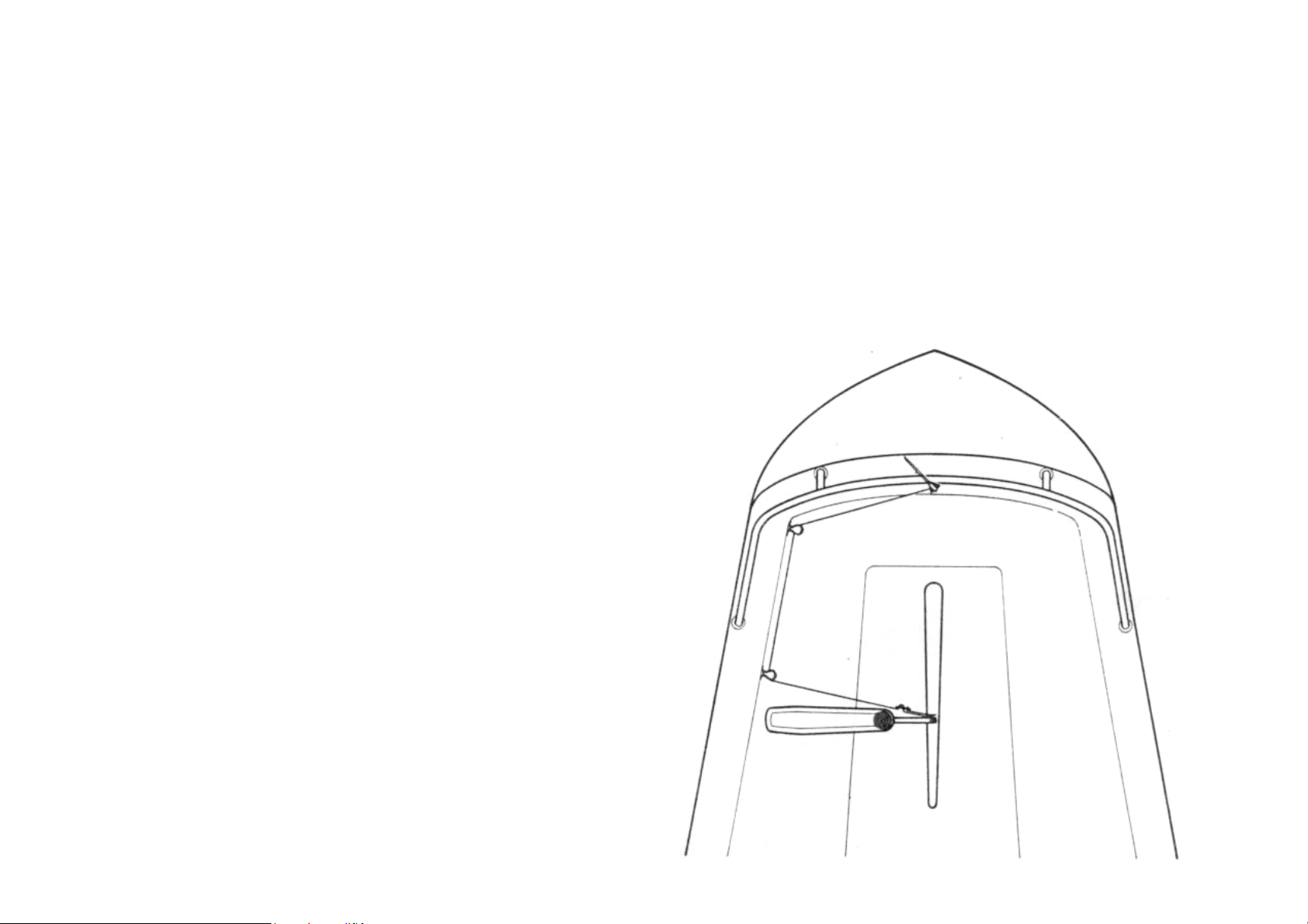
To complete installation of the wind vane
rom
the base of the mounting mast must be connected to
the pushrod. You will see that when the feedback
cord is pulled out of the mounting mast against
spring tension, backlash free rotational movement
are provided for leading the
feedback cord to the tiller. Normally only one
block is necessary to obtain a clear run out but .
occasionally two blocks may be necessary to avoid
obstructions such as the mainsheet. The final
of the actuator
unit as shown so that the final run of the feedback
cord is orientated nearly at right angles to the
tiller. It is important that the final fairlead is
positioned below the centreline of the pushrod so
as a tendency
lubrication of the jack plug
absolutely watertight.
Two small blocks
fairlead should be positioned aft
horizontal rail o
clear wind on both t
deck obstruction.
Feedback linkage
off course error.
attachment, the feedback drive cord emerging f
that the spring tension on the cord h
to pull the pushrod down onto the tiller pin.
of the wind vane transducer results.
Page 15

Feedback Linkage
9
Page 16

Finally, a loop is formed on the end of the
feedback cord after cutting to length and made fast
by means of the plastic adjustor slide provided.
The end of the loop is pos
itioned so that the
feedback cord is just under tension when attached
to the hook on the end of the pushrod in the fully
retracted position. This ensures that the feedback
cord is under tension over the full stroke of the
ver tensioned,
the remaining free scope of movement may not be
sufficient to accommodate the full stroke of the
pushrod and may cause damage to the feedback
mechanism at the full extremity of pushrod travel.
After adjusting the cord tension as described
ove, carefully check that the remaining scope of
feedback cord movement is sufficient to accommodate
After rigging the feedback cord, check that the
wind vane transducer head rotates smoothly over the
d movement. Backlash free vane
head movement is essential to ensure accurate
pushrod. If the feedback cord is o
ab
the full stroke of the pushrod.
full stroke of pushro
steering performance.
Page 17

10
Page 18

Operation
After completing the installation you should carry
out the following functional test to familiarise
f with the system before attempting sea
The autopilot is fitted with a 4 position thumb
operated rotary switch located on the upper case.
when the thumb
clockwise
ining 3 positions of the control
selects compass operation for 'calm' weather
selects compass operation for 'rough' sea
In this position minor yawing motions caused by
ction are neglected. The autopilot will
respond only to changes in mean course, and thus
the duty cycle and power consumption will be
selects wind vane control and enables convenient
e
Hold the unit towards the tiller and rotate the
compass dial until the cardinal point graduations
are approximately aligned with your main steering
raduation
on the compass dial then automatically homes to
Functional test procedure
yoursel
trials.
Operation under compass control
•
compass.
• Switch to calm and note that the north g
The autopilot is switched off
control wheel is in the fully antiposition. The rema
switch provide the following functions.
Calm
conditions.
Rough
conditions.
wave a
substantially reduced.
Vane
transfer of control mode when the wind van
attachment is fitted.
magnetic north.
Main Control Switch
Page 19

11
Page 20

Rotate the compass dial in small increments until
the end of the pushrod remains settled over the
compass dial clockwise to retract the pushrod and
clockwise to extend it. Note that after making
adjustments, it is necessary to release the compass
dial to allow the compass to realign with the
its mooring, you
will see that small variations in heading cause the
unit to apply corrective action to the rudder. Now
and note that the frequency of
ed with a wind vane attachment
the following familiarisation test may be carried
Connect the wind vane jack plug to the main
actuator and attach the feedback cord to the end
Set the wind vane head into its most sensitive
y tilting the head forward until the
vane is almost vertical. Then grip the mounting
mast just above its base and slowly rotate until
the vane feathers into wind. In this position the
ransfer the sensing mode
Note that small variations in wind direction will
now cause the actuator unit to apply corrective
action to the rudder. This is how the Autohelm 1000
ttle further and note
how the tiller takes up a new position to one side.
This is how trim corrections are made for weather
sensitises the wind
ne, and you will note that the frequency of
Preferably, initial trials should be carried out in
reasonably calm conditions and with plenty of sea
ocedure is
Steer onto a fixed heading under engine or sail
Holding the pushrod towards the tiller, rotate
the compass dial until it is approximately
s
Allow the compass to automatically align with the
earth's magnetic field and then adjust the
compass dial further until the end of the pushrod
llow the
tiller pin and clutch onto the tiller. Rotate the
anti-
earth's magnetic field.
If the yacht is swinging about
switch to rough
corrective action is reduced.
Operation under wind vane control
If the system is fitt
out.
•
of the pushrod.
•
position b
vane will flutter evenly between the buffers.
• Switch over to vane to t
to wind vane control.
Rotate the mounting mast a li
or lee helm when under sail.
Finally, tilt the vane head back until the vane is
nearly horizontal. This deva
corrective rudder action is noticeably reduced.
Operation under sail
room.
The following familiarisation pr
recommended.
Compass control
•
and hold the course steady.
•
aligned with the yacht's main steering compas
and switch to calm.
•
is approximately positioned over the tiller pin.
• Clip the pushrod onto the tiller and a
autopilot to take over.
functions when under sail.
Page 21

12
Page 22

After allowing the boat to steady onto an
automatically controlled heading, carry out small
incremental adjustments to the compass dial until
the vessel steadies on to the desired heading.
justment of the compass
The vessel may now be steered onto any other
heading by adjusting the compass dial. If the
autopilot appears to be working continuously due
to sea conditions, switch over to rough. The rate
When the system is fitted with a wind vane
attachment it will in general be easier to set up
under compass control first as described above, and
s under wind vane control are best
carried out when sailing to windward slightly off
When the vessel is sailing steadily under a
magnetically controlled heading, the wind vane
mast should be rotated to feather the vane to
ane and the actuator will then
controlled heading, carry out small rotational
adjustments to the vane mounting mast until you
um
Note that to adjust the yacht's heading you rotate,
the vane stanchion in the same direction as you
would the tiller. You will find also that to trim
your course only very small movements should be
epeat the above procedure broad reaching and
finally running down wind by progressively
slackening the sheets and slowly rotating the
The pushrod is held into engagement with the tiller
erely by the weight of the actuator unit. This
method of engagement is secure and has been adopted
for safety reasons to allow the pushrod to be
easily disengaged when manual override becomes
le when sailing under automatic
pilot control to pay strict attention to sail
balance. Good sail balance is particularly
When a yacht is sailing badly out of balance,
luff
violently to windward. When hand steering, this
tendency is corrected by applying sufficient
weather helm to hold the original course until the
gust subsides. A simple autopilot, however, does
not understand the need for weather helm and will,
ore, allow the yacht to luff to windward
until sufficient helm is applied to achieve a new
•
Note that clockwise ad
dial will alter course to port.
•
of working will then reduce substantially.
Wind vane control
then to switch over to wind vane control.
First trial
the wind
•
applied to the vane stanchion.
• R
vane to bring the vessel onto the new headings.
Disengagement
pin m
necessary.
Operating hints
Sail balance
It is always advisab
wind.
• Switch over to v
respond to variations in wind direction.
• When the vessel has steadied onto a wind-
are satisfied that you are sailing on an optim
course to windward.
essential in gusty conditions and strong winds.
sudden gusts will generally cause it to
theref
state of balance.
Page 23

13
Page 24

Furthermore, it will maintain the luffed heading
for as long as the need for increased weather helm
'persists. Contrary to popular opinio
n a
proportional steering autopilot will not maintain a
constant heading when the yacht's balance changes.
Thus sailing badly out of balance in varying wind
strengths will always give rise to excessive course
ng
the mainsail slightly more than you would when hand
On longer passages when a constant compass course
may be steered for hours on end, variations in wind
strength and direction will almost certainly cause
e reasons given
above, variations in standing helm will cause the
autopilot to steer slightly away from the set
course. In the case of the Autohelm 1000, if 5
degrees of additional weather helm is required as a
the
course steered by the autopilot will
correspondingly change by approximately 20 degrees.
Thus when passage making, if a change in compass
heading is observed, the original course should
trimming sails to obtain
ate of balance. Alternatively,
providing weather helm has not become excessive,
the yacht may be trimmed back on to the original
adjusting the autopilot's compass
ically to
operate at near maximum sensitivity. High vane
sensitivity is essential to ensure optimum
hauled
and usually does not result in excessive actuator
activity. The sensitivity of the vane may be
tilting the entire unit backwards on its
clevis mounting. This has the effect of increasing
the 'dead band' of the vane sensor by allowing up
to a maximum of 15 degrees course variation to
occur before automatic correction is applied. When
ary to sail a very accurate course,
lowering the sensitivity of the vane in this manner
will reduce the number of corrections made and
hence reduce power consumption. In heavy weather or
turbulent wind conditions, the duty cycle of the
sensitising
sensitising the wind vane under
these conditions will not affect the accuracy of
Vane sensitivity adjustment
Normally the wind vane is set almost vert
penetration to windward when sailing close-
wander. This tendency is best overcome by reefi
steering.
changes in helm balance. For the sam
result of rising wind strength, for example,
ideally be restored by rethe original st
heading by resetting.
reduced by
it is not necess
autopilot can usually be lowered by dethe wind vane. De-
the mean course steered.
Page 25

14
Page 26

When the wind vane attachment is not fitted it is
he basic magnetic sensing unit
under both engine and sail. It should be borne in
mind, however, that the compass sensor is
internally gimballed to cope with a maximum angle
of heel of 30 degrees, and will not operate beyond
necessary to lay
slightly off the wind when sailing long passages
hauled to prevent becoming backed by gradual
Wind vane control is always more efficient when
hauled when it will ensure that
age is taken of changing wind
direction to ensure optimum penetration to
windward. In steady wind conditions, wind vane
control will. Usually give best results on all
When the wind is abaft the beam and unsteady in
direction surprisingly large
variations I in apparent wind direction can occur.
Under these conditions compass control generally
When the wind vane attachment is fitted the system
to automatically tack the vessel by
alternately switching over from compass to wind
vane. This is done by setting the vane to control
on the longest tack and the compass sensor on the
other. Tacking is then simply achieved by switching
o the other leaving you free to
As a final caution. it is very easy to relax
keeping, and this temptation must
be avoided however clear the sea ahead may appear
two
just the time it takes to
After use, the Autohelm 1000 system is easily
stowed by unclipping the actuator unit from its
mounting, and removing the vane transducer from its
re system can then be stowed
All moving parts of the system have been lubricated
for life at the factory. Therefore no maintenance
whatsoever will be required. Should a fault
ed in the
original packing case for repair and servicing,
which will be carried out speedily and at a
Selection of transducer
Tacking in enclosed waters
possible to use t
this heel angle. It will also be
closeshifts in wind direction.
sailing closeimmediate advant
other points of sailing.
strength and
improves course keeping accuracy.
can be set up
over from one mode t
handle the sheets.
Watch-keeping
permanent watch-
to be. Remember that a large ship can cover
miles in five minutes brew a cup of coffee!
Stowage
mounting mast. The enti
easily in a small locker.
Maintenance
develop, the entire unit should be return
moderate cost.
Page 27

15
Page 28

Raymarine Ltd.
Anchorage Park
Portsmouth
Hampshire
PO3 5TD
Tel 023 9269 3611
Page 29

Fax 023 9269 4642
www.raymarine.com
 Loading...