


Technical Service Manual
Phone: 508-653-0082
Fax: 508-653-1736
MOTION
TECHNOLOGY, INC. LIMITED WARRANTY
1. Nature of Warranty
This equipment is warranted to be free of manufacturing defects in workmanship and materials for one (1) full year beginning from the date of original retail purchase and subject to the limitations set forth below. The controls package consisting of the main circuit board and keypad are warranted for three (3) years. Any part found to be defective during the warranty period will be replaced with new or rebuilt replacement parts free of charge by Motion Technology, Inc. (MTI). Shipping charges are me responsibility of the purchaser. Service labor is included for a period of one (1) full year beginning from me date of original retail purchase when performed by an authorized MTI service company or designated agent based on straight time rates for work performed during normal working hours. This labor coverage is limited to a fifty (SO) mile radius (each way) and/or 1 hours travel time of a customers location. Any and all other service travel charges will be the responsibility of the customer.
2. Scope of the Warranty
This Warranty is extended to the original purchaser for products purchased and retained in the 50 states of me U.S.A. and the District of Columbia. This Warranty shall not be effective unless the equipment was purchased from a dealer or other person authorized by MTI to sell its equipment.
The attached Warranty registration card must be fully completed and mailed within ten (10) days-of receipt to assure the validity of this limited Warranty.
4. How to Obtain Service
Notification of a defect in the material or workmanship of the equipment, shall be to the MTI Factory Service Manager at me number shown below or me dealer from whom you purchased the equipment. We want you to be a satisfied customer. If a problem does come up that cannot be resolved to your satisfaction, please let us know. Write to Service Manager, Motion Technology, Inc., 6 Huron Drive, Natick, MA 01760-1315. Please be sure to include the Model Number, Serial Number, and the date of original purchase.
5. Exclusion of Incidental or Consequential Damage
Repair or replacement under this Warranty is the purchasers sole and exclusive remedy. Neither MTI nor the dealer from whom you are purchasing this equipment will be responsible for any and all incidental or consequential damages, resulting from the use of the equipment or from breach of any express or implied warranty on this equipment. These warranties are in lieu of all other warranties, express or implied, including, but not limited to, the implied warranties of merchantability or fitness for a particular purpose.
3. Exclusions from Coverage of the Warranty
This Warranty does not cover any damage to the equipment resulting from accident, misuse, abuse or negligence, failure to follow operating, cleaning and periodic maintenance instructions, mishandling, alteration, failure to install in strict conformity with local fire and building codes and regulations, ordinary wear and tear resulting from use, failure to change filters using only manufacturers' supplied at the recommended intervals, or if the installation does not comply with set-up arid installation instructions. The equipment shall not have been previously altered, repaired or serviced by anyone other than a service facility authorized by MTI to render such service
6. Legal Rights of Warranty
Retain mis Warranty. It gives the purchaser specific legal rights. The purchaser may also have other rights which vary from state to state. MTI suggests that the dealer's dated bill of sale be ratained as evidence of the date of purchase. Some states do not allow the exclusion or limitation of incidental or consequential damages, or allow limitations on how long an implied Warranty lasts, so the above limitations or exclusions may not apply to all purchasers.
Technical Service/Support: (888) 664-6640

ELECTRIC FRYER MODEL MTI-5
FEATURES:
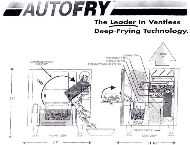
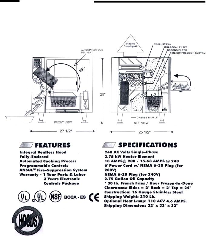
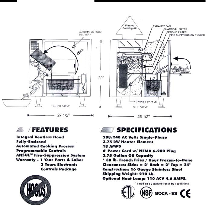
Integral Ventless Hood
Fully-Enclosed
Automated Cooking Process
Programmable Controls
ANSUL9 Fire-Suppression System
Warranty: 1 Year Parts/Labor and
3 Years Electronic Controls Package
SPECIFICATIONS:
240 AC Volts Single-Phase
17.5 AMPS @ 4.2 kW Heater Element 6' Power Cord w/NEMA 6-20 Plug
2 Gallon Oil Capacity
20 Lb. French Fries/Hour (Frozen to Done*) Clearances: Sides = 2" Back = 2" Top = 24" Construction: 1 B Gauge Stainless Steel Shipping Weight: 140 Lb.
Optional Heat Lamp: 110 ACV 4.6 AMPS
* based on a three minute french fry cook time.
800-348-2976
Get Fried at www.autofry.com
AUTOFRY
ELECTRIC FRYER MODEL MTI-10
— The lender in fully enclosed rentless frying technology —
800-348-2976
Get Fried at www.autofry.com
AUTOFRY
ELECTRIC FRYER MODEL FFG-10
— The leader in fully enclosed rentless frying technology —
800-348-2976
Get Fried at www.autofry.com
AUTOFRY
Electric Fryer Model MTI-40E
800-348-2976
GET Fried at www.autofry.com
Motion Technology, Inc. |
PH: (508) 653-0082 FX: (508) 653-1736 |
AUTOFRY
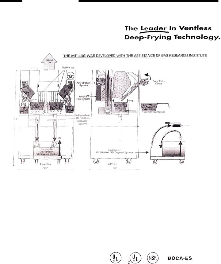
Gas Fryer Model MTI-40G*
*Gas Must Vent To The Outside
FEATURES: |
SPECIFICATIONS: |
Integral Ventless Hood |
130,OOBTU/Hr. Total |
Fully-Enclosed |
120 ACV 15 Amp. Required |
Independent Fry Vats |
120 Volt 4.5 Amp. Oil Filtration System |
Dual Basket/Automated Food Delivery |
50 Lb. Oil Capacity |
Programmable Controls |
10% Cold Zone |
Built-in Oil Filtration/Disposal System |
60 Lb. French Fries/Hour (Frozen to Done*) |
ANSUL® Fire-Suppression System |
Shipping Weight: 400 Lb. |
Stainless Steel Construction |
Clearances: Sides = 2" Back = 4" Top = 24" |
Warranty: 1 Year Parts/Labor and |
Class "B" Gas Vent Required ( Consult Local Codes] |
3 Years Electronics Controls Package |
Available for natural gas or propane |
|
* based on a three minute french fry cook time. |
800-348-2976
Get Fried at wwuu.autofry.com
Motion Technology, Inc. |
PH: [508] 553-0082 |
FX: [508] 653-1736 |
Motion Technology, Inc. |
|
FFG-10 MTI-10 |
REV 002 1/00 |
||
|
|
|
|
|
|
|
Model Name |
FFG-10 |
MTI-10 |
MTI-10 |
|
|
Voltage |
208 Volt - 240 Volt |
208 Volt - 240 Volt |
208 Volt* -240 Volt |
|
|
Wattage |
3750 ( N/A for 240 Volt) |
3750 both 208 & 240 |
4160 (208)& 4800 (240) |
|
|
Amperage |
18.03 (208) & 15.63 (240) |
18.03 (208) & 15.63(240) |
20 amps |
|
|
Hz |
50/60 |
50/60 |
50/60 |
|
|
Phase |
1 |
1 |
1 |
|
|
Plug Configuration |
NEMA6-20 |
6-30 (208) & 6-20 (240) |
NEMA 6-30 |
|
|
Serial Numbers |
1500-A through 4936-A |
4890-A through 6553-10 |
6554-10& Up |
|
|
Thermistor Style |
RTD |
RTD |
"K" Type Thermocouple |
|
|
Controller Style |
Milwaukee (10079) |
Milwaukee (10079) |
NCC(10079K) |
|
|
Note |
|
|
*208 Volt, 4160 Watt Special Order |
|
|
Listings |
ETL, NSF, CSA |
UL, NSF,CSA |
UL, NSF, CSA |
|
|
|
|
|
|
|
|
Changes |
No Longer Manufactured |
Using Ansul Fire System |
3 Amp Fuse on 2nd side of Transformer |
|
|
Serial Number Ranges |
4936-A Last |
4890-10 |
7197-10 |
|
|
Changes |
|
MTI-10 UL Listing |
|
|
|
Serial Number Ranges |
|
4890-10 |
|
|
|
Changes |
|
Watlow RTD Probes |
|
|
|
Serial Number Ranges |
|
5966-10 |
|
|
|
Changes |
|
Class CC Fuse |
|
|
|
Serial Number Ranges |
|
5475-10 |
|
|
|
|
|
|
|
|
Motion Technology, Inc |
AFI-50MTI-5 |
Rev 002 1/00 |
Model Name |
AFI-5 |
MTI-5 |
MTI-5 (Far East Export Modified) |
|
Voltage |
120 Volt |
240 Volt |
200 Volt |
|
Wattage |
1725 |
4200 |
3000 |
|
Amperage |
14.375 |
17.5 |
15 |
|
Hz |
50/60 |
50/60 |
50/60 |
|
Phase |
1 |
1 |
1 |
|
Plug Configuration |
NEMA15-5 |
NEMA6-20 |
NEMA 6-20 |
|
Serial Numbers |
Up to 1999-5 |
2000-5 & Up |
2000-5 & Up |
|
Thermistor Style |
"K" Thermocouple |
"K" Thermocouple |
"K" Thermocouple |
|
Controller Style |
NCC Self Service |
NCC(10079K) |
NCC(10079K) |
|
Note |
Export Only |
Replaces AFI-5 |
Replaces AFI-5 |
|
Listings |
UL,NSF,CSA,CE |
UL, NSF, CSA, CA |
UL, NSF, CSA, CE |
|
Changes |
|
Removed external On/Off Switch |
|
|
Serial Numbers Range |
|
2097-5 |
|
|
|
|
|
|
|
|
|
|
|
|
Motion Technology, Inc |
MTI-40 MTI-40E |
Rev 002 1/00 |
Model Name |
MTI-401PH |
MTI-40 3PH |
MTI-40E 1PH |
MTI-40E 3PH |
Voltage |
240 Volt |
240 Volt |
240 Volt |
240 Volt |
Wattage |
12000 |
12000 |
16000 |
16000 |
Amperage |
50 |
28.9 |
66.67 |
38.54 |
Hz |
50/60 |
50/60 |
50/60 |
50/60 |
Phase |
1 |
3 |
1 |
3 |
Plug Configuration |
Hard Wired |
NEMA 15-50 |
Hard Wired |
NEMA 15-50 |
Serial Numbers |
1000-40 through 1065-40 |
1000-40 through 1065-40 |
1111-40 and Up |
1111-40 and Up |
Thermistor Style |
RTD |
RTD |
"K" Type Thermocouple |
"K" Type Thermocouple |
Serial Numbers |
1066-40 through 1110-40 |
1066-40 through 1110-40 |
|
|
Thermistor Style |
"K" Type Thermocouple |
"K" Type Thermocouple |
|
|
Controler Style |
Milwaukee (10079) |
Milwaukee (10079) |
NCC (10079K) |
NCC (10079K) |
Serial Numbers |
1000-40 throughl 065-40 |
1000-40 through 1065-40 |
|
|
Controler Style |
NCC(10079K) |
NCC 10079K) |
|
|
Serial Numbers |
1066-40 through 1110-40 |
1066-40 through 1110-40 |
|
|
Note |
Integral Oil Filtration Syst. |
Integral Oil Filtration Syst. |
Removable Oil Filtration |
Removable Oil Filtration |
Listings |
UL, NSF, CSA |
UL, NSF,CSA |
UL,NSF,CSA |
UL,NSF,CSA |
Changes |
|
|
2" Ball Valves |
2" Ball Valves |
Serial Number Range |
|
|
1111-40 |
1111-40 |
Changes |
|
|
Three Blowers |
Three Blowers |
Serial Number Range |
|
|
1111-40 Thru 1141-40 |
1111-40 Thru 1141-40 |
Changes |
|
|
Single Blower |
Single Blower |
Serial Number Range |
|
|
1142-40 |
1142-40 |
Changes |
|
|
Dual Vat |
Dual Vat |
Serial Number Range |
|
|
1111-40 |
1111-40 |
Changes |
Motor Numbers |
Motor Number |
Motor Number |
Motor Number |
|
40042 (R.S)&10042 (L.S.) |
40042 (R.S)& 10042 (L.S) |
40042R (R.S) & 40042L |
40042R (R.S.) & 40042L (L..S.) |
Serial Number Range |
1110-40 and Lower |
1110-40 and Lower |
1111-40 and Up |
1111-40 and Up |
AUTOFRY Models FFG-10 & MTI-10 Safety Circuit
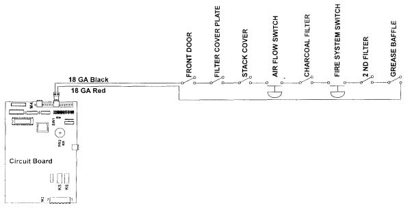
Figure 1 - Safety Circuit Overview
The safety circuit is comprised of 8 separate switches that are wired in series. They terminate at the circuit board 10079 at terminal M4 positions 8 & 9 and circuit board 10079K at J3. Should any of these switches open the MDR (Mercury Displacement Relay) coil will de-energize and the display at the keypad will go blank or display Sft.
The exception to this is as follows,
If, after the cook cycle has started, one of the safeties opens, the AUTOFRY will continue the cook cycle. At the completion of the cook cycle the AUTOFRY will de-energize the MDR coil and shut off.
The AUTOFRY cannot be re-started until the open safety circuit condition is corrected. However, if the oil temperature is at or above 150° F the fan will continue to run.
There are three basic switch types utilized in this circuit,
1.Plunger style momentary switches (part no. 10028-S)
•For all the filters, the front door, the stack cover and the filter cover plate
2.Diaphramtype air flow switch.(X06313)
•To monitor the airflow.
3.Normally open Air pressure switch (no part no.)
•To monitor the tank pressure at the fire system.
MTI Form SAFT10 Rev. 002 1/99
AUTOFRY Models FFG-10 & MTI-10 Safety Circuit
Access to all but the front door safety, that is located behind the keypad, will be made from the rear of the AUTOFRY.
Trouble Shooting:
1.Press the ON key, the fan starts and runs for 10-12 second then shuts off and there is never a display at the key pad or the display reads Sft.
•Check that the front door is closed and making contact with the safety.
•Check for a worn door gasket or a loose door latch.
•Ensure that all filters are installed and that the filter cover plate is installed.
•Excessive grease build-up at one of the safety switches.
•Inspect the tank pressure gauge at the fire system sight window. It needs to be in or slightly
over the charged zone.
•Look for any obstructions at the stack cover.
•Check that the stack cover louvers are open. The fan should be visible through the louvers.
•Airflow switch out of adjustment.
•Loose connections at any of the safety switches.
2.The AUTOFRY operates; however, it shuts off just after a cook cycle, fan continues to run.
•Loose connection to a safety switch.
•Airflow switch out of adjustment.
3.The AUTOFRY shuts off by its self at no specific time, fan continues to run, Sft at display.
•Loose connection to a safety switch.
•Airflow switch out of adjustment.
4.The AUTOFRY was just cleaned and now it does not start up, the fan does not operate or the display reads Sft.
•Debris caught in fan blades, air-flow switch does not close.
•Loose or no connection to main power.
AUTOFRY Models FFG-10 & MTI-10 Safety Circuit
Inspecting, adjusting and testing the safety circuit:
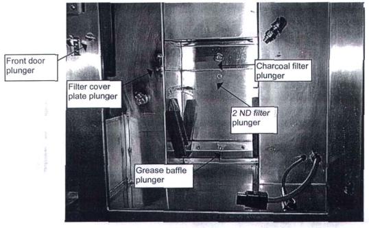
Prior to accessing the rear chamber, it is a good idea to test the physical operation of each of the plunger style switches to ensure that they are in good working order.
Figure 2 - Front view of plunger switches
Ensure that all components are installed and are making a solid contact with there respective switches.
NOTE:
The fan must be operating in order to check the airflow switch. Prior to removing the rear access cover do the following to start the fan,
•Unplug the heater plug and the RTD plug or Thermocouple Plug from the bottom of the heater box.
•Press the ON button at the keypad.
•When the display shows 417 or Prb press the OFF key. At this time the wait light should be blinking and the fan should be operating.
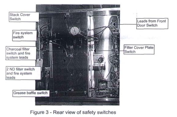
Remove the rear access panel.
Check that all the wire terminals are securely fastened to the safety switches. Check for any breaks in the circuit.
MTI Form SAFT10 Rev. 002 1/99 |
3 |
AUTOFRY Models FFG-10 & MTI-10 Safety Circuit
Check that the termination at M4 or J3 on the circuit board is secure and that the red and black wires are screwed in tightly to the 2-pin plug. With all components installed in the AUTOFRY and the front door closed perform a continuity test across all the safety switches.
NOTE:
There may be three loose wires at the fire system; these wires are for the building egress pressure switch. Some state codes require that the fryer be linked to the building fire alarm, this switch is for those applications only and need not be connected to the AUTOFRY safety circuit.
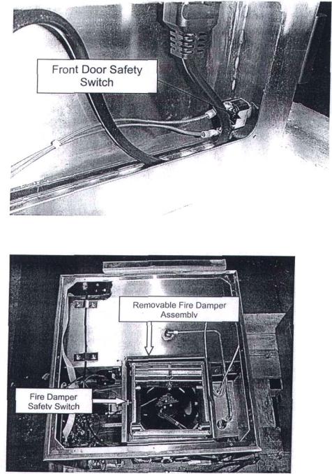
The Model MTI-5 safety circuit functions the same as the safety system for the models FFG-
10 and MTI-10. The only notable differences are as follows...
The front door safety switch is located at the lower right hand comer of the front door opening. Access to this switch is made through the access panel at the left side of the
AUTOFRY.
The other difference involves the removable top panel and fire damper assembly and it's safety switch.
The illustration shown at the left shows a top view of the MTI-5 with the top panel removed.
Highlighted is the removable fire damper. To the left of the damper is the safety switch. The damper must be installed in order for this switch to close and complete the safety circuit. If the damper assembly should close the airflow
switch will open the safety circuit deenergizing the heater circuit and displaying Sft on the keypad display.
NOTE: Removal of the top panel also aids in working on other related components.
Adjusting the MPL air switch
In order to adjust the air switch you need to:
1.Unplug the AUTOFRY from the wall
2.Turn the unit around to gain access to the rear panel
3.Remove the rear access panel
4.You will see the air switch; the switch is black in color and round (about the size of
a hockey puck). You will notice either a clear or gray air hose attached to it).
5.Remove the sealant fro the center of the air switch
CAUTION!! You must remove all of the sealant from the center of the switch, so you do not strip out the adjusting screw.
6.Using a 1/8" Alien wrench turn the adjusting screw 2 complete turns to the left, which is in a clockwise direction.
7.Install the rear cover.
8.Plug in the AUTOFRY and turn it on.
See the attached diagram for reference,
Remove sealant from allen set screw
AUTOFRY Models FFG-10 & MTI-10 Safety Circuit
Additional Notes and Information:
Depending on the model and date of manufacture the air flow switch may not look like or be located in the same position as the one shown in figure 5. Some models incorporated a small black box type air switch that is located on the component board, (follow the clear plastic hose to locate this switch). This style switch is adjustable; however, the technician will need to use a 1/16" flat screwdriver to adjust the sensitivity on this switch.
If the AUTOFRY has been stored in bellow zero temperatures for any extended period of time (1 week or more) the liquid in the fire system cylinder may have "Jelled". This condition will affect the pressure switch on the system tank. Allow the system to thaw at room temperature until the switch responds.
If the installation of the AUTOFRY is at high altitude there may not be sufficient air pressure to activate the airflow switch. It may be necessary to adjust the switch to its lowest setting.
If the AUTOFRY is exposed to extreme high temperature an over-heating at the circuit board may result. This condition could result in intermittent shutdowns simulating a safety circuit fault. Allow adequate ventilation at the rear of the AUTOFRY.
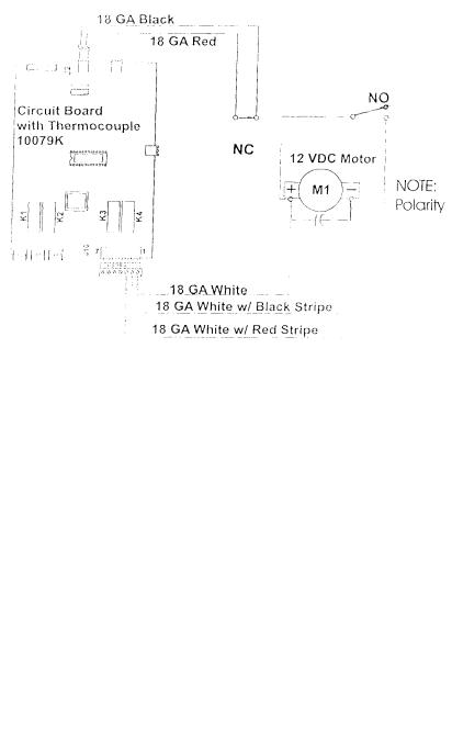
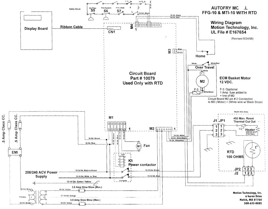
AUTOFRY Models FFG-10 and MTI-10 Basket Motor Circuit Basket Motor Circuit Overview:
Figure 1 - Basket Motor Circuit for Circuit Boards with an RTD
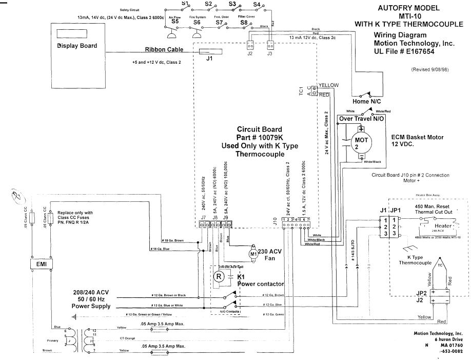
Figure 1-A Basket Motor Circuit for Circuit Boards with Thermocouple (Polarity Reversed)
AUTO FRY Models FFG-10 and MTI-10 Basket Motor Circuit The basket motor circuit is
comprised of the following components,
2.Wire Assemblies as follows
•Motor Harness (part no. 8-10)
•NC switch normally closed connection white with red stripe (part no. 12-10)
•NO switch common connection black (part no. 18-10)
•NO switch normally open connection red (part no. 17.10) • Circuit board (part no. 10079 or
10079K)
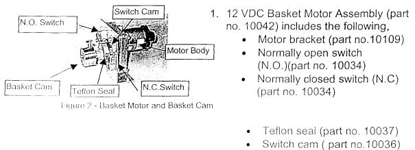
AUTOFRY Models FFG-10 and MTI-10 Basket Motor Circuit
The motor assembly is secured to the motor mount within the electrical chamber with 2 ea. 1/4-20 x 5/8" bolts and lock washers. The motor shaft is fitted with a Teflon seal. The shaft then protrudes through a clearance hole into the cook chamber where the basket cam is then attached to the shaft and held secure with a 1/4-28 x 5/8" bolt and a small drop of medium thread locker.
Details on removal and testing the basket motor are covered in these instructions.
AUTOFRY Models FFG-10 and MTI-10 Basket Motor Circuit
The basket motor functions to lift and lower the wire food basket through it's "Cycle". This cycle consists of 7 positions,
1.Ready
2.Cook
3.Drain
4.Dispense
5.Shake
6.2nd Dispense
7.Return to ready
These positions are controlled by the switch cam, micro switches and through programs set in the EPROM of the microprocessor.
At the start of a cycle the motor will rotate counter clockwise from the ready position to the cook position.
This is a timed rotation set in program # 14 At the completion of the cook cycle the basket motor will rotate clockwise to the Drain position.
This is a timed rotation set in program # 10
The drain time is set at 12 seconds in program #11. At the completion of the drain time the basket motor will rotate clockwise to the dispense position.
This is controlled when the notch in the switch cam contacts the normally open switch.
The basket motor will rotate counter clockwise from the dispense position to the shake position, hold there for a second then return to the dispense position. There is no sellable programming for this position in the circuit board with the RTD it is in program # 19 for the circuit board with a thermocouple. At the completion of the 2nd dispense position the motor will rotate clockwise until the notch in the switch cam contacts the normally closed switch.
If the basket motor fails to rotate or if it fails to return to the ready position with in 10 seconds the display at the keypad will show the error code ofA04.
AUTOFRY Models FFG-10 and MTI-10 Basket Motor Circuit
Trouble shooting:
1.No motor rotation and an A04 at the display.
•Loose or no connection at the positive terminal of the motor (white wire with a black stripe) or,
at the negative terminal of the motor (solid white wire).
•Locked rotor at the motor.
•Striped gears.
•Burned traces at the circuit board due to over rotation.
•Frozen or burned relay at the circuit board
2.Motor rotates as follows,
•Right to cook
•Left to drain
•Left to dispense
•Right to shake
•Left to dispense
•Right past the ready position continuing for 10 seconds prior to stopping. An A04 at the display with an audible tone. One or all of the
following is the cause.
•Loose or no connection at the normally closed switch (black and or red wires)
•Loose or no connection at the M4 terminal positions 1 & 2. 9 black and or red wires)
3.Motor rotates as follows.
Note: There will not be an A04 error in this case
•Right to cook.
•Right to 45° then stops
•Relays will "Click"
•Right to ready position.
A loose or no connection at the normally open switch (solid white wire or the white wire with the red stripe) causes this
4.The motor functions however the cam does not rotate or the basket does not move.
•Loose basket cam.
•Worn motor shaft.
•Basket not properly installed.
5.Basket motor rotates however it is very slow.
•Transformer secondary side voltage drop
•Incorrect fuses at the Primary side fuse holder.
AUTOFRY Models FFG-10 and MTI-10 Basket Motor Circuit
Replacing the Basket Motor Assembly (part no. 10042)
1.Disconnect the AUTOFRY from main power.
2.Open the main door and remove the following components.
•The wire food basket.
•The heater box assembly
•The oil pot.
3.With a 7/16" wrench loosen and remove the basket cam from the motor shaft.
•Inspect the "D" shaped hole for signs of wear and replace the cam if necessary.
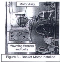
4.Remove the rear access panel from the AUTOFRY
5.With a 7/16" open end wrench or small 1/4" drive ratchet and 7/16"socket loosen and remove the 2 motor mounting bolts and lock washers.
6.Disconnect all wires.
•If helpful tag each wire.
1.Prior to installing a new motor clean all areas of any oil traces.
2.Inspect the replacement motor.
•The replacement motor has been tested at the factory, however, it should be inspected for any damage incurred in shipping.
•Ensure that the Teflon seal is present, if not use the seal from the old motor.
3.Inspect all wiring and replace if necessary.
4.Inspect the circuit board for any burned traces (see figure 4).
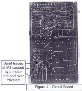
AUTOFRY Models FFG-10 and MTI-10 Basket Motor Circuit
•At the backside of the circuit board inspect the traces just above the M2 or J10 terminal block. If these traces are burned replace the circuit board (see figure 4).
•Attach all wires to their appropriate switches and motor terminals.
1. Place the new motor into position on the motor mount bracket and loosely secure with the 1/4 -20 bolts and lock washers.
2. Attach the basket cam to the motor shaft at the interior of the cook chamber.
•Place a small drop of medium strength thread locker to the 1/4 -28 bolt prior to installation.
•There is a "D" shaped hole in the
basket cam that will fit over the motor shaft, it may be necessary to de-bur the hole in order for it to fit over the shaft.
• Ensure that the bolt makes full contact on the motor shaft to prevent the cam from slipping.
3. Tighten the motor mounting bolts to a hand tight fit with a 7/16" wrench of socket.
AUTOFRY Models FFG-10 and MTI-10 Basket Motor Circuit
Testing the motor:
VERY IMPORTANT!
Test the motor without the basket in place.
If the switch cam notch is not in position at the normally closed switch and the AUTOFRY is turned on the motor will rotate 360° until it contacts the switch. If the basket is in place it will cause damage to the motor and or the circuit board.
Dry testing the AUTOFRY equipped with an RTD ONLY. You can not dry test an AUTOFRY with a thermocouple unless you have a thermocouple simulator.
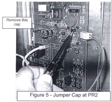
1.At the circuit board locate and remove the small black jumper cap from position PR2 located 1/4" below the beeper (see figure 5).
• Removing this cap will send a false temperature to the controller allowing the AUTOFRY to operate with out heating the oil.
2.Install the safety circuit jumper into positions 8 & 9 at M4 at the circuit board.
3.Install the oil pot and the heater box.
4.Plug the RTD plug into the heater box.
VERY IMPORTANT!
Do Not plug the heater plug in at this time. Do Not install the wire food basket.
 Loading...