


Technical Service Manual
Phone: 508-653-0082
Fax: 508-653-1736

MOTION
TECHNOLOGY, INC.
LIMITED WARRANTY
1. Nature of Warranty
This equipment is warranted to be free of manufacturing
defects in workmanship and materials for one (1) full year
beginning from the date of original retail purchase and
subject to the limitations set forth below. The controls
package consisting of the main circuit board and keypad
are warranted for three (3) years. Any part found to be
defective during the warranty period will be replaced with
new or rebuilt replacement parts free of charge by Motion
Technology, Inc. (MTI). Shipping charges are me
responsibility of the purchaser. Service labor is included for
a period of one (1) full year beginning from me date of
original retail purchase when performed by an authorized
MTI service company or designated agent based on straight
time rates for work performed during normal working
hours. This labor coverage is limited to a fifty (SO) mile
radius (each way) and/or 1 hours travel time of a customers
location. Any and all other service travel charges will be
the responsibility of the customer.
2. Scope of the Warranty
This Warranty is extended to the original purchaser for
products purchased and retained in the 50 states of me
U.S.A. and the District of Columbia. This Warranty shall
not be effective unless the equipment was purchased from a
dealer or other person authorized by MTI to sell its
equipment.
The attached Warranty registration card must be fully
completed and mailed within ten (10) days-of receipt to
assure the validity of this limited Warranty.
4. How to Obtain Service
Notification of a defect in the material or workmanship of
the equipment, shall be to the MTI Factory Service
Manager at me number shown below or me dealer from
whom you purchased the equipment. We want you to be a
satisfied customer. If a problem does come up that cannot
be resolved to your satisfaction, please let us know. Write
to Service Manager, Motion Technology, Inc., 6 Huron
Drive, Natick, MA 01760-1315. Please be sure to include
the Model Number, Serial Number, and the date of
original purchase.
5. Exclusion of Incidental or
Consequential Damage
Repair or replacement under this Warranty is the
purchasers sole and exclusive remedy. Neither MTI
nor the dealer from whom you are purchasing this
equipment will be responsible for any and all
incidental or consequential damages, resulting from
the use of the equipment or from breach of any express
or implied warranty on this equipment. These
warranties are in lieu of all other warranties, express
or implied, including, but not limited to, the implied
warranties of merchantability or fitness for a
particular purpose.
3. Exclusions from Coverage of the
Warranty
This Warranty does not cover any damage to the equipment
resulting from accident, misuse, abuse or negligence,
failure to follow operating, cleaning and periodic
maintenance instructions, mishandling, alteration, failure
to install in strict conformity with local fire and building
codes and regulations, ordinary wear and tear resulting
from use, failure to change filters using only manufacturers'
supplied at the recommended intervals, or if the installation
does not comply with set-up arid installation instructions.
The equipment shall not have been previously altered,
repaired or serviced by anyone other than a service facility
authorized by MTI to render such service
6. Legal Rights of Warranty
Retain mis Warranty. It gives the purchaser specific legal
rights. The purchaser may also have other rights which
vary from state to state. MTI suggests that the dealer's
dated bill of sale be ratained as evidence of the date of
purchase. Some states do not allow the exclusion or
limitation of incidental or consequential damages, or allow
limitations on how long an implied Warranty lasts, so the
above limitations or exclusions may not apply to all
purchasers.
Technical Service/Support: (888) 664-6640
ELECTRIC FRYER MODEL MTI-5
FEATURES:
Integral Ventless Hood
Fully-Enclosed
Automated Cooking Process
Programmable Controls
ANSUL
Warranty: 1 Year Parts/Labor and
3 Years Electronic Controls Package
9
Fire-Suppression System
SPECIFICATIONS:
240 AC Volts Single-Phase
17.5 AMPS @ 4.2 kW Heater Element
6' Power Cord w/NEMA 6-20 Plug
2 Gallon Oil Capacity
20 Lb. French Fries/Hour (Frozen to Done*)
Clearances: Sides = 2" Back = 2" Top = 24"
Construction: 1 B Gauge Stainless Steel
Shipping Weight: 140 Lb.
Optional Heat Lamp: 110 ACV 4.6 AMPS
* based on a three minute french fry cook time.
800-348-2976
Get Fried at www.autofry.com
AUTOFRY
ELECTRIC FRYER MODEL MTI-10
— The lender in fully enclosed rentless frying technology —
800-348-2976
Get Fried at www.autofry.com
AUTOFRY
ELECTRIC FRYER MODEL FFG-10
— The leader in fully enclosed rentless frying technology —
800-348-2976
Get Fried at www.autofry.com
AUTOFRY
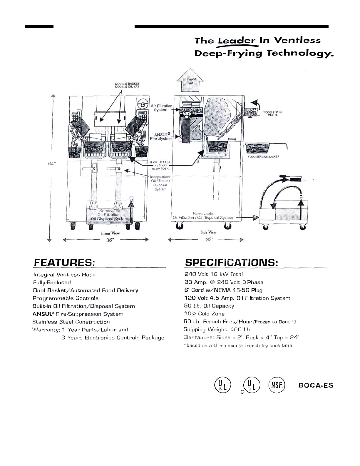
Electric Fryer Model MTI-40E
800-348-2976
GET Fried at www.autofry.com
Motion Technology, Inc. PH: (508) 653-0082 FX: (508) 653-1736
AUTOFRY
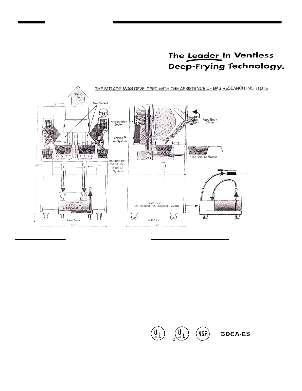
Gas Fryer Model MTI-40G*
*Gas Must Vent To The Outside
FEATURES:
Integral Ventless Hood
Fully-Enclosed
Independent Fry Vats
Dual Basket/Automated Food Delivery
Programmable Controls
Built-in Oil Filtration/Disposal System
ANSUL® Fire-Suppression System
Stainless Steel Construction
Warranty: 1 Year Parts/Labor and
3 Years Electronics Controls Package
SPECIFICATIONS:
130,OOBTU/Hr. Total
120 ACV 15 Amp. Required
120 Volt 4.5 Amp. Oil Filtration System
50 Lb. Oil Capacity
10% Cold Zone
60 Lb. French Fries/Hour (Frozen to Done*)
Shipping Weight: 400 Lb.
Clearances: Sides = 2" Back = 4" Top = 24"
Class "B" Gas Vent Required ( Consult Local Codes]
Available for natural gas or propane
* based on a three minute french fry cook time.
800-348-2976
Get Fried at wwuu.autofry.com
Motion Technology, Inc. PH: [508] 553-0082 FX: [508] 653-1736

Motion Technology, Inc. FFG-10 MTI-10 REV 002 1/00
Model Name FFG-10 MTI-10 MTI-10
Voltage 208 Volt - 240 Volt 208 Volt - 240 Volt 208 Volt* -240 Volt
Wattage 3750 ( N/A for 240 Volt) 3750 both 208 & 240 4160 (208)& 4800 (240)
Amperage 18.03 (208) & 15.63 (240) 18.03 (208) & 15.63(240) 20 amps
Hz 50/60 50/60 50/60
Phase 1 1 1
Plug Configuration NEMA6-20 6-30 (208) & 6-20 (240) NEMA 6-30
Serial Numbers 1500-A through 4936-A 4890-A through 6553-10 6554-10& Up
Thermistor Style RTD RTD "K" Type Thermocouple
Controller Style Milwaukee (10079) Milwaukee (10079) NCC(10079K)
Note
*208 Volt, 4160 Watt Special Order
Listings ETL, NSF, CSA UL, NSF,CSA UL, NSF, CSA
Changes No Longer Manufactured Using Ansul Fire System 3 Amp Fuse on 2nd side of Transformer
Serial Number Ranges 4936-A Last 4890-10 7197-10
Changes
Serial Number Ranges
Changes
Serial Number Ranges
Changes
Serial Number Ranges
MTI-10 UL Listing
4890-10
Watlow RTD Probes
5966-10
Class CC Fuse
5475-10

Motion Technology, Inc AFI-50MTI-5 Rev 002 1/00
Model Name AFI-5 MTI-5 MTI-5 (Far East Export Modified)
Voltage 120 Volt 240 Volt 200 Volt
Wattage 1725 4200 3000
Amperage 14.375 17.5 15
Hz 50/60 50/60 50/60
Phase 1 1 1
Plug Configuration NEMA15-5 NEMA6-20 NEMA 6-20
Serial Numbers Up to 1999-5 2000-5 & Up 2000-5 & Up
Thermistor Style "K" Thermocouple "K" Thermocouple "K" Thermocouple
Controller Style NCC Self Service NCC(10079K) NCC(10079K)
Note Export Only Replaces AFI-5 Replaces AFI-5
Listings UL,NSF,CSA,CE UL, NSF, CSA, CA UL, NSF, CSA, CE
Changes
Serial Numbers Range
Removed external On/Off Switch
2097-5

Motion Technology, Inc MTI-40 MTI-40E Rev 002 1/00
Model Name MTI-401PH MTI-40 3PH MTI-40E 1PH MTI-40E 3PH
Voltage 240 Volt 240 Volt 240 Volt 240 Volt
Wattage 12000 12000 16000 16000
Amperage 50 28.9 66.67 38.54
Hz 50/60 50/60 50/60 50/60
Phase 1 3 1 3
Plug Configuration Hard Wired NEMA 15-50 Hard Wired NEMA 15-50
Serial Numbers 1000-40 through 1065-40 1000-40 through 1065-40 1111-40 and Up 1111-40 and Up
Thermistor Style RTD RTD "K" Type Thermocouple "K" Type Thermocouple
Serial Numbers 1066-40 through 1110-40 1066-40 through 1110-40
Thermistor Style "K" Type Thermocouple "K" Type Thermocouple
Controler Style Milwaukee (10079) Milwaukee (10079) NCC (10079K) NCC (10079K)
Serial Numbers 1000-40 throughl 065-40 1000-40 through 1065-40
Controler Style NCC(10079K) NCC 10079K)
Serial Numbers 1066-40 through 1110-40 1066-40 through 1110-40
Note Integral Oil Filtration Syst. Integral Oil Filtration Syst. Removable Oil Filtration Removable Oil Filtration
Listings UL, NSF, CSA UL, NSF,CSA UL,NSF,CSA UL,NSF,CSA
Changes
Serial Number Range
Changes
Serial Number Range
Changes
Serial Number Range
Changes
Serial Number Range
2" Ball Valves 2" Ball Valves
1111-40 1111-40
Three Blowers Three Blowers
1111-40 Thru 1141-40 1111-40 Thru 1141-40
Single Blower Single Blower
1142-40 1142-40
Dual Vat Dual Vat
1111-40 1111-40
Changes Motor Numbers Motor Number Motor Number Motor Number
40042 (R.S)&10042 (L.S.) 40042 (R.S)& 10042 (L.S)
40042R (R.S) & 40042L
40042R (R.S.) & 40042L (L..S.)
Serial Number Range 1110-40 and Lower 1110-40 and Lower 1111-40 and Up 1111-40 and Up
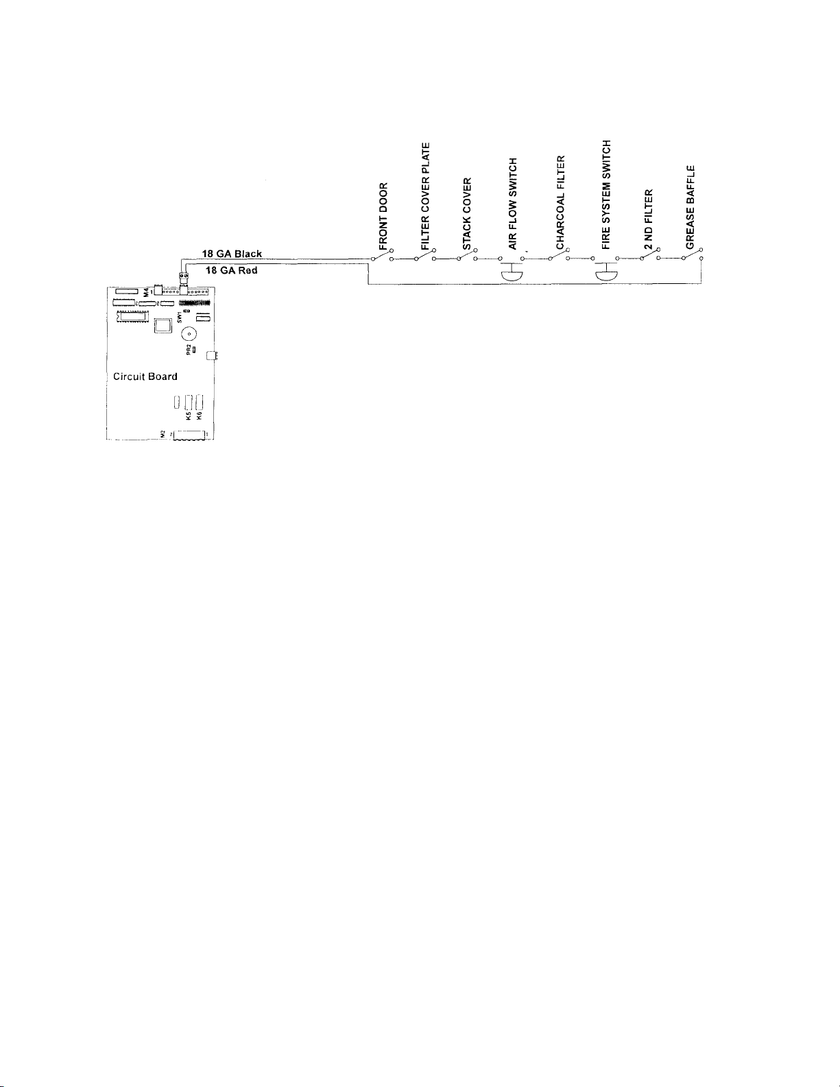
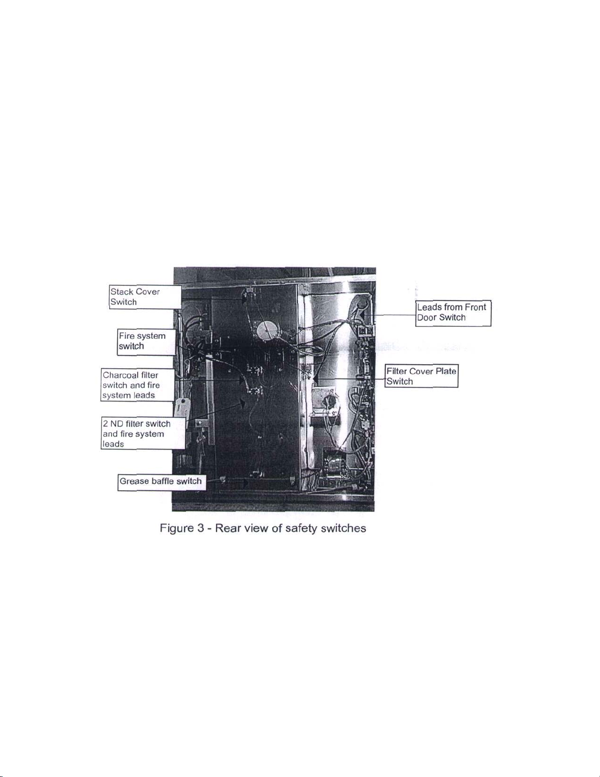
AUTOFRY Models FFG-10 & MTI-10 Safety Circuit
Figure 1 - Safety Circuit Overview
The safety circuit is comprised of 8 separate switches that are wired in series. They
terminate at the circuit board 10079 at terminal M4 positions 8 & 9 and circuit board 10079K
at J3. Should any of these switches open the MDR (Mercury Displacement Relay) coil will
de-energize and the display at the keypad will go blank or display Sft.
The exception to this is as follows,
If, after the cook cycle has started, one of the safeties opens, the AUTOFRY will continue the
cook cycle. At the completion of the cook cycle the AUTOFRY will de-energize the MDR coil
and shut off.
The AUTOFRY cannot be re-started until the open safety circuit condition is corrected.
However, if the oil temperature is at or above 150° F the fan will continue to run.
There are three basic switch types utilized in this circuit,
1. Plunger style momentary switches (part no. 10028-S)
• For all the filters, the front door, the stack cover and the filter cover plate
2. Diaphramtype air flow switch.(X06313)
• To monitor the airflow.
3. Normally open Air pressure switch (no part no.)
• To monitor the tank pressure at the fire system.
MTI Form SAFT10 Rev. 002 1/99

AUTOFRY Models FFG-10 & MTI-10 Safety Circuit
Access to all but the front door safety, that is located behind the keypad, will be made from the rear of
the AUTOFRY.
Trouble Shooting:
1. Press the ON key, the fan starts and runs for 10-12 second then shuts off and there is never a
display at the key pad or the display reads Sft.
• Check that the front door is closed and making contact with the safety.
• Check for a worn door gasket or a loose door latch.
• Ensure that all filters are installed and that the filter cover plate is installed.
• Excessive grease build-up at one of the safety switches.
• Inspect the tank pressure gauge at the fire system sight window. It needs to be in or slightly
over the charged zone.
• Look for any obstructions at the stack cover.
• Check that the stack cover louvers are open. The fan should be visible through the louvers.
• Airflow switch out of adjustment.
• Loose connections at any of the safety switches.
2. The AUTOFRY operates; however, it shuts off just after a cook cycle, fan continues to run.
• Loose connection to a safety switch.
• Airflow switch out of adjustment.
3. The AUTOFRY shuts off by its self at no specific time, fan continues to run, Sft at display.
• Loose connection to a safety switch.
• Airflow switch out of adjustment.
4. The AUTOFRY was just cleaned and now it does not start up, the fan does not operate or the display
reads Sft.
• Debris caught in fan blades, air-flow switch does not close.
• Loose or no connection to main power.
AUTOFRY Models FFG-10 & MTI-10 Safety Circuit
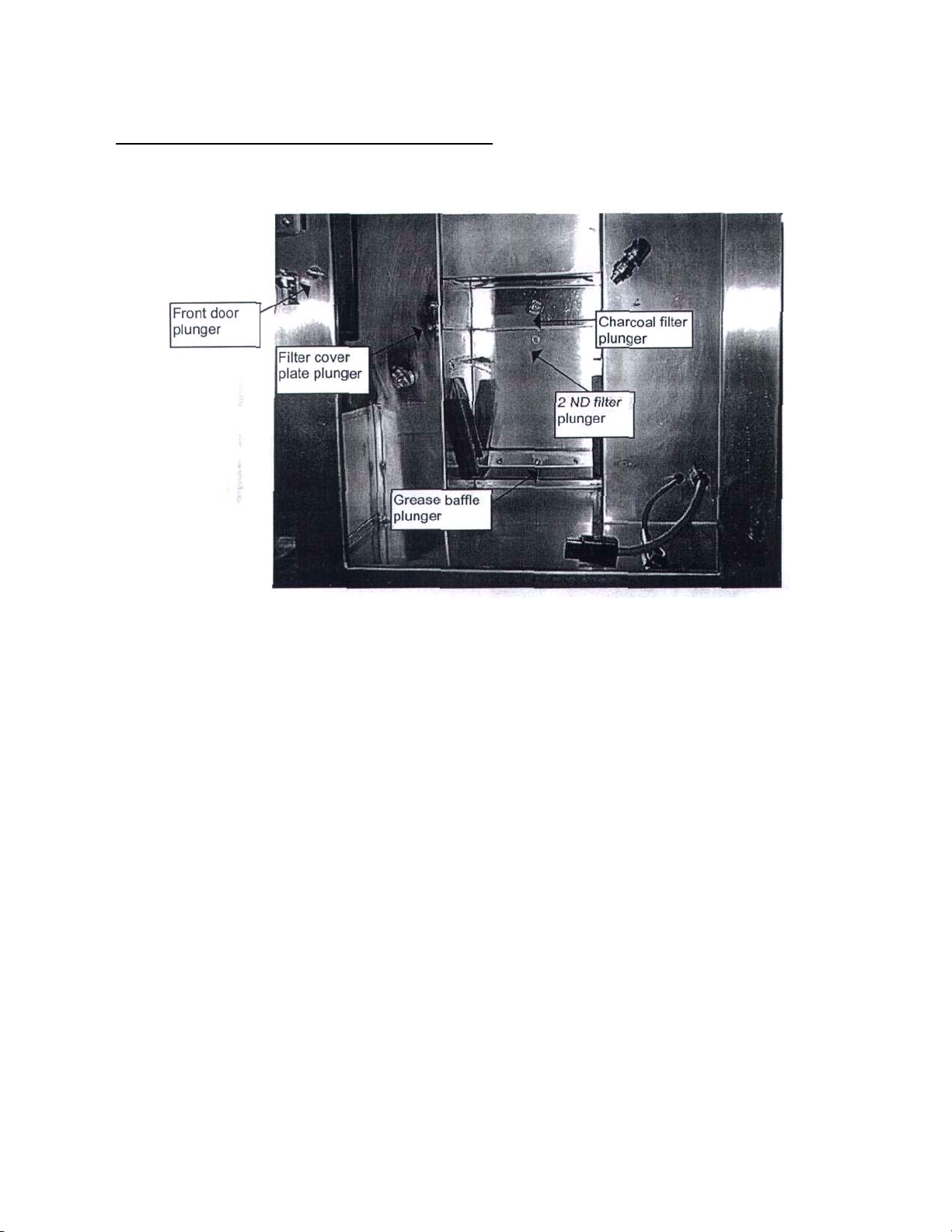
Inspecting, adjusting and testing the safety circuit:
Prior to accessing the rear chamber, it is a good idea to test the physical operation of each of the
plunger style switches to ensure that they are in good working order.
Figure 2 - Front view of plunger switches
Ensure that all components are installed and are making a solid contact with there respective
switches.
NOTE:
The fan must be operating in order to check the airflow switch. Prior to removing the rear access
cover do the following to start the fan,
• Unplug the heater plug and the RTD plug or Thermocouple Plug from the bottom of the
heater box.
• Press the ON button at the keypad.
• When the display shows 417 or Prb press the OFF key. At this time the wait light should
be blinking and the fan should be operating.
Remove the rear access panel.
Check that all the wire terminals are securely fastened to the safety switches.
Check for any breaks in the circuit.
MTI Form SAFT10 Rev. 002 1/99 3
AUTOFRY Models FFG-10 & MTI-10 Safety Circuit
Check that the termination at M4 or J3 on the circuit board is secure and that the red and black
wires are screwed in tightly to the 2-pin plug. With all components installed in the AUTOFRY and
the front door closed perform a continuity test across all the safety switches.
NOTE:
There may be three loose wires at the fire system; these wires are for the building egress
pressure switch. Some state codes require that the fryer be linked to the building fire alarm, this
switch is for those applications only and need not be connected to the AUTOFRY safety circuit.
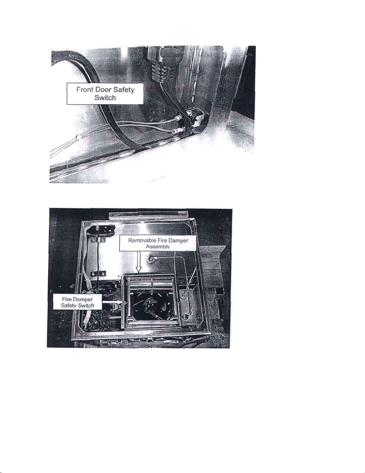
The Model MTI-5 safety circuit functions the same as the safety system for the models FFG10 and MTI-10. The only notable differences are as follows...
The front door
safety switch is
located at the
lower right hand
comer of the front
door opening.
Access to this
switch is made
through the
access panel at
the left side of the
AUTOFRY.
The other difference involves the removable top panel and fire damper assembly and it's
safety switch.
The illustration shown at
the left shows a top view
of the MTI-5 with the top
panel removed.
Highlighted is the
removable fire damper.
To the left of the damper
is the safety switch. The
damper must be installed
in order for this switch to
close and complete the
safety circuit. If the
damper assembly should
close the airflow
switch will open the
safety circuit deenergizing the heater
circuit and displaying
Sft on the keypad
display.
NOTE: Removal of the top panel also aids in working on other related components.
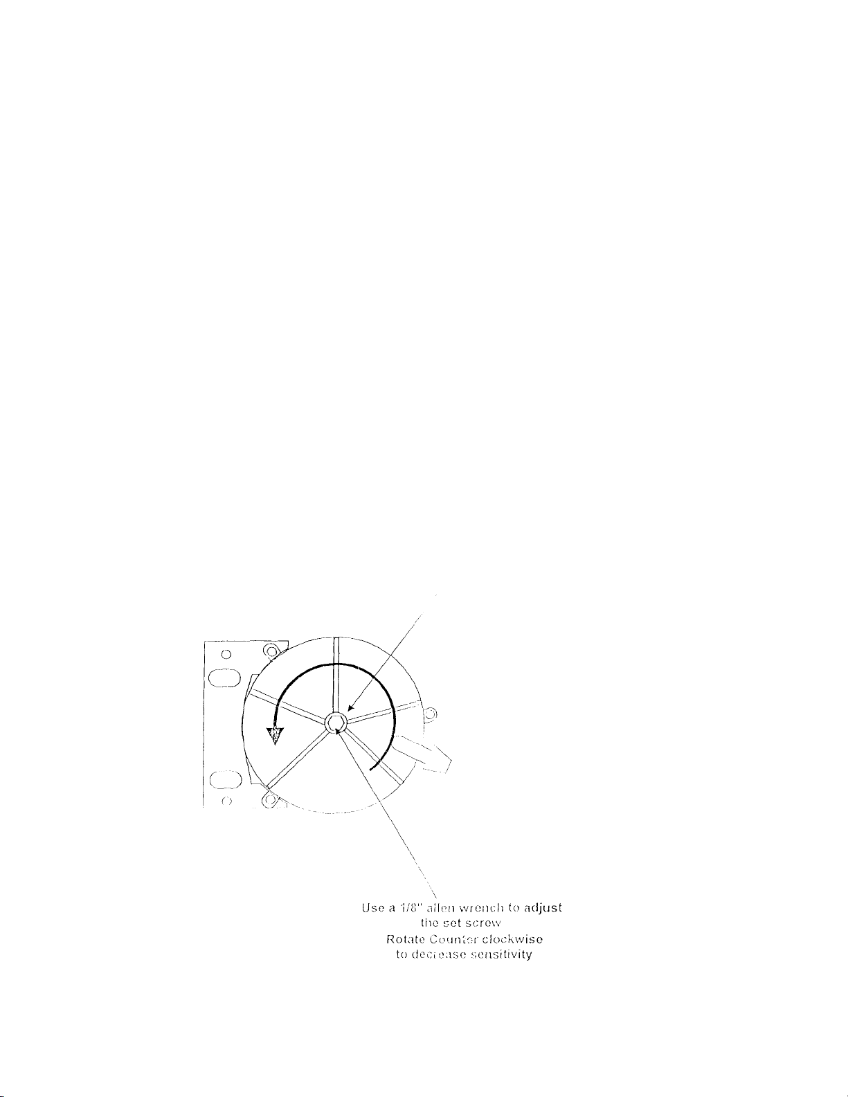
Adjusting the MPL air switch
In order to adjust the air switch you need to:
1. Unplug the AUTOFRY from the wall
2. Turn the unit around to gain access to the rear panel
3. Remove the rear access panel
4. You will see the air switch; the switch is black in color and round (about the size of
a hockey puck). You will notice either a clear or gray air hose attached to it).
5. Remove the sealant fro the center of the air switch
CAUTION!! You must remove all of the sealant from the center of the
switch, so you do not strip out the adjusting screw.
6. Using a 1/8" Alien wrench turn the adjusting screw 2 complete turns to the left,
which is in a clockwise direction.
7. Install the rear cover.
8. Plug in the AUTOFRY and turn it on.
See the attached diagram for reference,
Remove sealant from allen set screw

AUTOFRY Models FFG-10 & MTI-10 Safety Circuit
Additional Notes and Information:
Depending on the model and date of manufacture the air flow switch may not look
like or be located in the same position as the one shown in figure 5. Some models
incorporated a small black box type air switch that is located on the component board,
(follow the clear plastic hose to locate this switch). This style switch is adjustable;
however, the technician will need to use a 1/16" flat screwdriver to adjust the sensitivity on
this switch.
If the AUTOFRY has been stored in bellow zero temperatures for any extended
period of time (1 week or more) the liquid in the fire system cylinder may have "Jelled".
This condition will affect the pressure switch on the system tank. Allow the system to thaw
at room temperature until the switch responds.
If the installation of the AUTOFRY is at high altitude there may not be sufficient air
pressure to activate the airflow switch. It may be necessary to adjust the switch to its
lowest setting.
If the AUTOFRY is exposed to extreme high temperature an over-heating at the
circuit board may result. This condition could result in intermittent shutdowns simulating a
safety circuit fault. Allow adequate ventilation at the rear of the AUTOFRY.
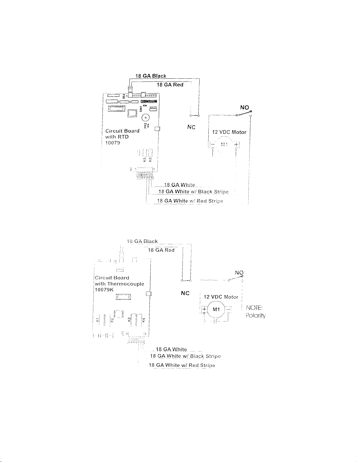
AUTOFRY Models FFG-10 and MTI-10 Basket Motor Circuit Basket Motor Circuit Overview:
Figure 1 - Basket Motor Circuit for Circuit Boards with an RTD
Figure 1-A Basket Motor Circuit for Circuit Boards with Thermocouple (Polarity Reversed)
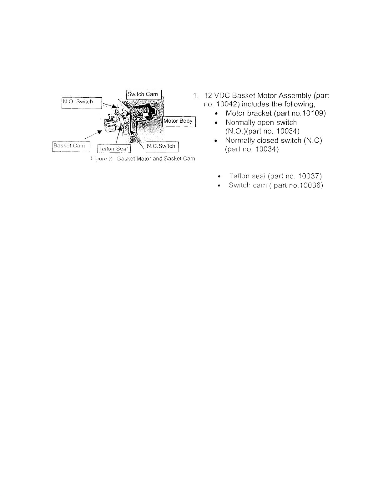
AUTO FRY Models FFG-10 and MTI-10 Basket Motor Circuit The basket motor circuit is
comprised of the following components,
2. Wire Assemblies as follows
• Motor Harness (part no. 8-10)
• NC switch normally closed connection white with red stripe (part no. 12-10)
• NO switch common connection black (part no. 18-10)
• NO switch normally open connection red (part no. 17.10) • Circuit board (part no. 10079 or
10079K)

AUTOFRY Models FFG-10 and MTI-10 Basket Motor Circuit
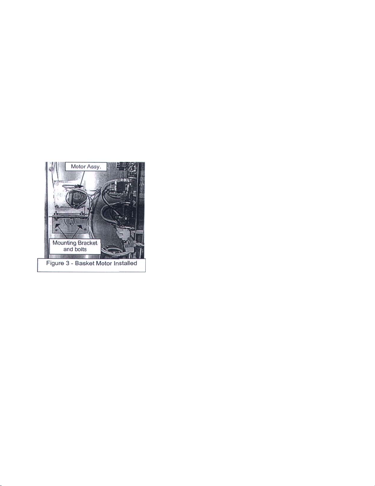
The motor assembly is secured to the motor mount within the electrical chamber with 2
ea. 1/4-20 x 5/8" bolts and lock washers. The motor shaft is fitted with a Teflon seal. The
shaft then protrudes through a clearance hole into the cook chamber where the basket
cam is then attached to the shaft and held secure with a 1/4-28 x 5/8" bolt and a small
drop of medium thread locker.
Details on removal and testing the basket motor are covered in these
instructions.

AUTOFRY Models FFG-10 and MTI-10 Basket Motor Circuit
The basket motor functions to lift and lower the wire food basket through it's "Cycle". This
cycle consists of 7 positions,
1. Ready
2. Cook
3. Drain
4. Dispense
5. Shake
6. 2nd Dispense
7. Return to ready
These positions are controlled by the switch cam, micro switches and through programs
set in the EPROM of the microprocessor.
At the start of a cycle the motor will rotate counter clockwise from the ready position to
the cook position.
This is a timed rotation set in program # 14 At the completion of the cook cycle
the basket motor will rotate clockwise to the Drain position.
This is a timed rotation set in program # 10
The drain time is set at 12 seconds in program #11. At the completion of the drain
time the basket motor will rotate clockwise to the dispense position.
This is controlled when the notch in the switch cam contacts the normally
open switch.
The basket motor will rotate counter clockwise from the dispense position to the shake
position, hold there for a second then return to the dispense position. There is no sellable
programming for this position in the circuit board with the RTD it is in program # 19 for
the circuit board with a thermocouple. At the completion of the 2nd dispense position the
motor will rotate clockwise until the notch in the switch cam contacts the normally closed
switch.
If the basket motor fails to rotate or if it fails to return to the ready position with in 10
seconds the display at the keypad will show the error code ofA04.

AUTOFRY Models FFG-10 and MTI-10 Basket Motor Circuit
Trouble shooting:
1. No motor rotation and an A04 at the display.
• Loose or no connection at the positive terminal of the motor (white wire with a black stripe) or,
at the negative terminal of the motor (solid white wire).
• Locked rotor at the motor.
• Striped gears.
• Burned traces at the circuit board due to over rotation.
• Frozen or burned relay at the circuit board
2. Motor rotates as follows,
• Right to cook
• Left to drain
• Left to dispense
• Right to shake
• Left to dispense
• Right past the ready position continuing for 10 seconds prior to
stopping. An A04 at the display with an audible tone. One or all of the
following is the cause.
• Loose or no connection at the normally closed switch (black and or red wires)
• Loose or no connection at the M4 terminal positions 1 & 2. 9 black and or red wires)
3. Motor rotates as follows.
Note: There will not be an A04 error in this case
• Right to cook.
• Right to 45° then stops
• Relays will "Click"
• Right to ready position.
A loose or no connection at the normally open switch (solid white wire or the white wire with the
red stripe) causes this
4. The motor functions however the cam does not rotate or the basket does not move.
• Loose basket cam.
• Worn motor shaft.
• Basket not properly installed.
5. Basket motor rotates however it is very slow.
• Transformer secondary side voltage drop
• Incorrect fuses at the Primary side fuse holder.
AUTOFRY Models FFG-10 and MTI-10 Basket Motor Circuit
Replacing the Basket Motor Assembly (part no. 10042)
1. Disconnect the AUTOFRY from main power.
2. Open the main door and remove the following components.
• The wire food basket.
• The heater box assembly
• The oil pot.
3. With a 7/16" wrench loosen and remove the basket cam from the motor shaft.
• Inspect the "D" shaped hole for signs of wear and replace the cam if necessary.
4. Remove the rear access panel from the AUTOFRY
5. With a 7/16" open end wrench or small 1/4" drive ratchet and 7/16"socket loosen and remove the 2
motor mounting bolts and lock washers.
6. Disconnect all wires.
• If helpful tag each wire.
1. Prior to installing a new motor clean all areas of any oil traces.
2. Inspect the replacement motor.
• The replacement motor has been tested at the factory,
however, it should be inspected for any damage incurred in
shipping.
• Ensure that the Teflon seal is present, if not use the seal from
the old motor.
3. Inspect all wiring and replace if necessary.
4. Inspect the circuit board for any burned traces (see figure 4).
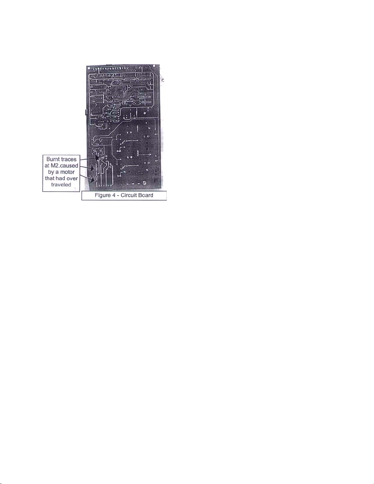
AUTOFRY Models FFG-10 and MTI-10 Basket Motor Circuit
• At the backside of the circuit board inspect the traces
just above the M2 or J10 terminal block. If these traces
are burned replace the circuit board (see figure 4).
• Attach all wires to their appropriate switches and
motor terminals.
1. Place the new motor into position on the motor
mount bracket and loosely secure with the 1/4 -20
bolts and lock washers.
2. Attach the basket cam to the motor shaft at the
interior of the cook chamber.
• Place a small drop of medium strength thread locker
to the 1/4 -28 bolt prior to installation.
• There is a "D" shaped hole in the
basket cam that will fit over the motor shaft, it may be necessary to de-bur the hole
in order for it to fit over the shaft.
• Ensure that the bolt makes full contact on the motor shaft to prevent
the cam from slipping.
3. Tighten the motor mounting bolts to a hand tight fit with a 7/16" wrench of socket.
AUTOFRY Models FFG-10 and MTI-10 Basket Motor Circuit
Testing the motor:
VERY IMPORTANT!
Test the motor without the basket in place.
If the switch cam notch is not in position at the normally closed switch and the AUTOFRY is turned on
the motor will rotate 360° until it contacts the switch. If the basket is in place it will cause damage to the
motor and or the circuit board.
Dry testing the AUTOFRY equipped with an RTD ONLY. You can not dry test an AUTOFRY with a
thermocouple unless you have a thermocouple simulator.
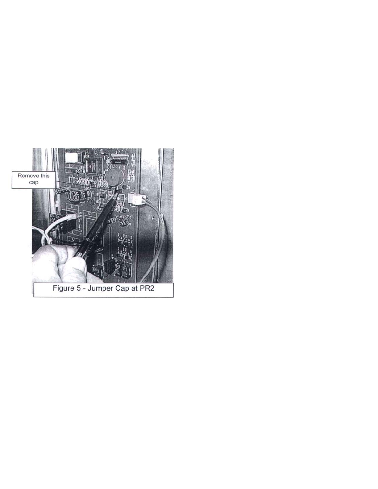
1. At the circuit board locate and remove the small black
jumper cap from position PR2 located 1/4" below the
beeper (see figure 5).
• Removing this cap will send a false temperature to the
controller allowing the AUTOFRY to operate with out
heating the oil.
2. Install the safety circuit jumper into positions 8 & 9 at
M4 at the circuit board.
3. Install the oil pot and the heater box.
4. Plug the RTD plug into the heater box.
VERY IMPORTANT!
Do Not plug the heater plug in at this time. Do Not install the
wire food basket.

AUTOFRY Models FFG-10 and MTI-10 Basket Motor Circuit
5. Plug the AUTOFRY into main power.
6. Press the ON key.
• There will be an audible tone.
• AUTOFY with RTD ONLY After 10-12 seconds there will be a display at the
keypad.
• AUTOFRY with a thermocouple the display will be instant.
• The basket motor may rotate to its home or ready position then back ready.
7. For the AUTOFRY equipped with a thermocouple you will need to install the heater plug
and the thermocouple plug and allow the oil temperature to reach its ready temperature in
order to test the basket motor.
8. Enter a 10-second time at the keypad and press START.
• You will want to carefully watch the basket cam to ensure it completes its 7-position
cycle. (See figure 6).
Once you have verified that the basket cycles are correct install the wire food basket.
The wire food basket should, at the ready position, be at a slight angle out of the oil as shown
in figure 7. If the basket is too high, product from the food entry chute will hit the side of the
basket and not enter the basket. If the basket rest too low, it may drive down into the heater
coils and damage the circuit. Ensure the basket rests as shown in figure 7. The height from the
floor of the cook chamber to the top right hand edge of the basket should be approximately 11"
-11.5" (see figure 7).

AUTOFRY Models FFG-10 and MTI-10 Basket Motor Circuit
To adjust the height of the wire food basket follow these instructions.
To raise the ready height of the basket
1. Remove the basket from the AUTOFRY.
2. With the flange of the basket resting on a sturdy
surface place a 10" adjustable wrench on the basket
rod end that fits into the basket cam, or the square end
(see figure 8).
3. Press down on the wrench to twist the rod slightly.
• A 1/8" twist in the rod will raise the ready height
approximately 1".
4. Re-install the basket into the AUTOFRY and inspect the height.
• Re-adjust as necessary to obtain the desired height. Keep in mind that if the
basket is too high product from the food entry chute will hit the side of the basket. It is good
practice to test the height using some product.
To lower the height of the basket at the ready position follow the step 1 & 2 from above.
Instead of pressing down on the basket rod pull up to twist the rod. Follow step 4 from
above.
VERY IMPORTANT! Once the motor has been installed and the basket height has been
adjusted (if necessary) replace the cap onto PR2.
Re-install the rear cover plate and plug in the RTD plug and test the AUTOFRY in a live
test condition.

AUTOFRY Model MTI-5 Basket Motor Circuit
VERY IMPORTANT
The AUTOFRY Model MTI-5 basket and motor rotates in a clockwise direction to
discharge product from the food basket. This rotation is the opposite of the Model
MTI-10. The basket motor assemblies are NOT interchangeable.
shown in figure 1 below.
The basket motor wiring is as
The basket motor may be protected with an in-line 3 Amp. Slow blow fuse located on
the plus side of the wiring.

FIGURE 2 -MTI-5 Basket Motor Assembly (Part Number 50042) - Front View of Switch Cam and Switches.
FIGURE 3 - Basket Cam and Set-Bolt
The basket cam is secured to the basket motor out-put shaft with an %-28 x 5/8" Hex Head bolt


Troubleshooting and diagnostics:
Helpful Hints: Rule out all operator error before dispatching service, for example:
Customer claims that, food entered does not dump out of the AUTOFRY.
Did they enter food before the ready light was on?
The basket will not dump until oil temperature is at 340°F
Did they enter food when the basket was in the second drain cycle?
Was the basket installed?
If either of these is the case then, the food is now in the bottom of
the oil pot.
A continued build up of food in the oil pot will:
Cause the food basket to "Jump" out of the basket rod receiver clip.
Cause excessive order and or smoke,
And may cause the limit to trip.
When testing, replacing or troubleshooting the basket motor always remove^ the food
basket. If the motor counter rotates it will cause damage to the basket motor, fuses or
circuit board.
It is strongly recommended that a thermocouple simulator be used to save time on the job
waiting for the oil to heat.
Basket motor rotates but basket does not lift:
Loose basket cam. Tighten as needed.
Stripped gears. Replace basket motor assembly.
Check that basket shaft has not jammed into basket rod receiver clip.
Replace basket motor assembly.
Display at keypad reads A04 and Basket motor does not rotate:
Press OFF to clear display and silence "beeping."
Check all wiring to motor. Repair as needed.
Check all wiring at circuit board. Repair as needed.
Check all fuses. Replace as needed.
Replace basket motor assembly.
Basket motor rotates 180 Degrees. The display then reads A04.
Check all wires.
Inspect micro switches and test with meter. Replace as needed.
Basket motor freezes in the drain or dump position:
Remove food basket. Shut off main power, wait 10 seconds and re-start
AUTOFRY. If basket motor continues to freeze in up position replace
circuit board. If problem persisted replace basket motor assembly.
Basket motor rotates very slowly:
Check voltage at transformer secondary side, there should be 12V dc
between the center tap (Orange wire) and each yellow wire. Replace
transformer.

Basket motor removal and installation instructions:
Tool required:
Multi-meter
Phillips head screw driver
7/16" open-end wrench.
7/16" socket.
1/4" Ratchet
Thermocouple simulator
Use caution when working with electrical power.
There is risk of shock.
Remove the food basket from the cook chamber.
With a 7/16" wrench, loosen the basket cam enough to remove it from the motor out-put
shaft.
NOTE: The bolt is held in place with a small drop of thread locker to
prevent loosening during operation.
Remove the rear access panel from the AUTOFRY.
Loosen and remove the two
1
/4" blots securing the motor assembly to it's mounting
bracket welded in the rear of the AUTOFRY.
IMPORTANT: Label all wires prior to removal.
Remove all labeled wires from the basket motor assembly. Compare the old motor to
the new motor to ensure that they are the same.
At this time' with the old motor assembly removed, you may find that the
problem with the motor is simply a defective or grease laden
switch. As long as the motor gears are in good shape then simply replace or clean the
switch.

Reinstall the New or Repaired Basket Motor Assembly
Connect the switch wires, that were labeled prior to removal of the old or re-built
motor (consult the wiring diagram).
Ensure that the motor shaft bushing is installed.
Slide the motor shaft all the way through the hole in the chamber wall.
Securely fasten the motor assembly to the motor mount with the 7/16" bolts and
lock washers.
Place a few drops of medium strength lock-tite or thread locker onto the basket
cam set bolt.
Slide the basket cam over the motor shaft and check the fit of the food basket.
Tighten the basket cam onto the motor shaft.
Make the final two wire connections to the motor plus and minus terminals.

Testing the Motor Installation:
DO NOT INSTALL THE BASKET UNTILL AFTER TESTING THE MOTOR
ROTATION. If the motor rotates in the wrong direction with the basket installed it
can cause gear damage and or blown fuses.
Install a thermocouple simulator onto the thermocouple socket at the heater box mounting
deck. Set the simulator for at least 340° F. This will allow the basket motor to function. Turn
on main power and press the ON button at the keypad.
The basket motor should rotate from ready to dump the back to ready. If it rotates
backwards check the motor wiring polarity.

AUTOFRY Model MTI-40 Basket Motor Circuit
Basket Motor Circuit Wiring Diagram for Serial Numbers 1111 -40 and Lower.
NOTE POLARITY AT MOTORS

AUTOFRY Model MTI-40 Basket Motor Circuit
Basket Motor Circuit Wiring Diagram for Serial Numbers 1110-40 and Higher.
NOTE POLARITY AT MOTORS

MTI-40 BASKET MOTORS
For MTI-40 Serial Numbers 1110-40 and lower use the following motor assembly. Part
numbers (all parts are viewed from the front of the AUTOFRY).
RIGHT SIDE 40042
LEFTSIDE 10042 (same as MTI-10)
For MTI-40 Serial Numbers 1111-40 and up use the following basket motor assembly.
Part numbers (all parts are as viewed from the front of the AUTOFRY).
RIGHT SIDE 40042R
LEFT SIDE 40042L

AUTOFRY Model MTI-40 Basket Motor Circuit
IMPORTANT
Motors cannot be interchanges from right to left.
IMPORTANT
Note the serial numbers prior to installing any motors. Always make a visual comparison
prior to installing any motor assemblies.
The AUTOFRY Model MTI-40 basket motor circuit for serial numbers 1110-40 and
LOWER have switch wiring as shown in the diagrams) below.
The diagram below shows the rear view of the basket motors for the Models MTI-10 with
serial numbers 1110-40 and lower. Note that the polarity has been reversed in order for the
motors to rotate counter - clockwise for the lefts side and clockwise for the right side. The
left side motor and wiring is identical to the Model MTI-10.

AUTOFRY Model MTI-40 Basket Motor Circuit
In the diagrams below are the wiring and switch illustrations for AUTOFRY models MTI-40E
and MTI-40G with serial numbers 1111-40 and higher. These motors are not
interchangeable with any other AUTOFRY Models nor will they work in MTI-40 Models with
serial numbers 1110-40 and lower.

AUTOFRY Model MTI-40 Basket Motor Circuit
As with all basket motor repairs it is important that the technician test the repair
WITHOUT the basket installed. This precaution will prevent damage to the basket motor
and circuit board in the event the polarity of the motor is incorrect.
Always test any fuses attached to the motor wiring and always test the fuses at the
primary side of the transformer prior to beginning any motor repair. Expensive and timeconsuming repairs may be avoided by following this advice.
The use of a thermocouple simulator for units equipped with a "K" type
thermocouple will also eliminate time-consuming heat-up delays.
When installing a new motor assembly ensure that the Teflon bushing is installed on the
motor shaft(s) and that a small drop of medium strength lock-tite is used on the Y4-28 cam
bolt. It is good practice to pre-install all wiring before installing the motor assembly.

AUTOFRY Model MTI-40 Basket Motor Circuit
For MTI-40 models with serial numbers of 1110-40 and LOWER the basket cam rotations
are as follows.
Basket Cam Position For MTI-40 with
Serial Numbers 1110-40 and LOWER
For MTI-40 models with serial numbers 1111 -40 and higher the basket cam will start in the
COOK position and lower only slightly at when the cook cycle is started.
Basket Cam Position For MTI-40E and MTI-40G with
Serial Numbers 1111 -40 and Higher

SERVICE REPLACEMENT OF BASKET RECEIVER CLIP
TOOLS NEEDED:
1. DRILL
2. 1/8" DRILL BIT
3. (2) 1/8"POPRIVITS
4. POP RIVIT GUN
STEPS FOR REPLACEMENT
1. Place new basket clip over old clip on the fryer
2. Drill 2 1/8" holes. 1 in the top and 1 in the bottom of the basket clip
3. Pop Rivit the new clip over the old clip and into the AUTOFRY
4. Install fry basket and check for proper fit
5. If the basket won't fit or is too tight, Grind a small portion of the basket rod
off and check the fit. Repeat if needed.

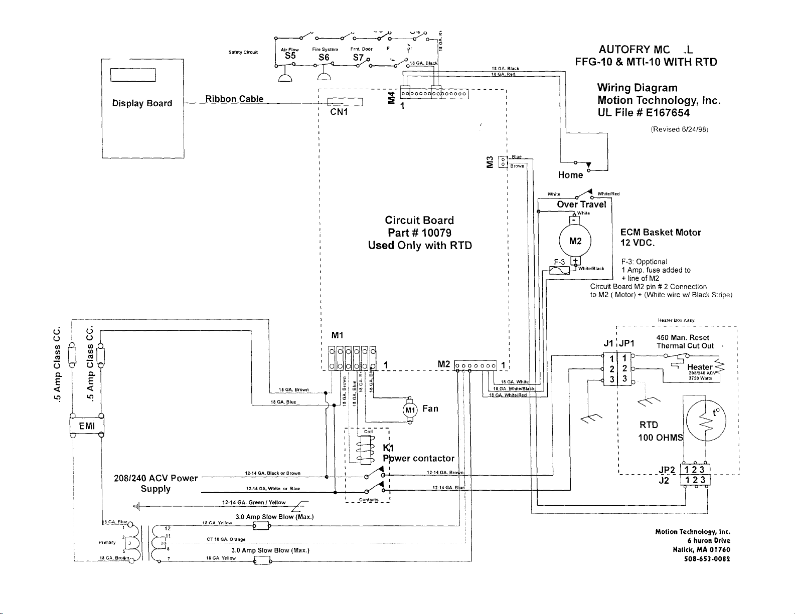
AUTOFRY Models FFG-10 and MTI-10 RTD Circuit
RTD (Resistance Temperature Detector) part no. 10065
System Overview:
The Circuit board receives signal strength readings from the RTD; those signals
are processed via the microprocessor on the circuit board. The EPROM
programming determines when the contactor coil should be opened or closed
based on oil temperature in degrees Celsius. The oil temperature is displayed at
the keypad display in degrees Fahrenheit.
If the RTD signal is interrupted while the machine is in the on mode, even
momentarily, the keypad will display 417 and the wait light at the keypad will
blink.
If the machine is in the off mode, the wait light will continue to blink.

AUTOFRY Models FFG-10 and MTI-10 RTD Circuit
Trouble Shooting:
Condition:
Blinking Wait light and 417 at display. Erratic temperature displays. Oil temperature over
400°F excessive smoking of oil and the high limit trips:
1. Inspect the oil level in the oil pot. The oil level should be approximately 2"
from the top edge of the oil pot.
2. Inspect the probe for visible damage.
3. Inspect the connection between the RTD plug and Cable and the heater box socket
(see figure 2).
4. Inspect the RTD cable for cracks and or cuts.
5. Inspect the rubber grommet at the chamber wall. If the grommet is missing the cable
may be shorting against the stainless steel chamber wall.
6. If all systems test OK at the front of the unit, remove the rear cover plate and inspect
the following.
7. If the problem persists,
• Fill the oil pot if necessary
• Test Probe & Replace if necessary (see Testing the RTD).
• Ensure that the connections at the RTD Plug and socket fit firmly.
• Clean any and all oil from the connections.
• Replace the plug and or socket if necessary.
• Replace the cable assembly if necessary.
• Replace the cable assembly if necessary.
• Replace the grommet and cable if necessary.
• The butt splice between the 18/2 cable assembly and the brown and blue #18
gauge wires that connect to the circuit board.
• The 2-pin connection at M3 on the circuit board.
• Check with a meter the continuity from the 2-pin connector to the RTD plug to
ensure the wiring is secure.
• Replace the circuit board.

AUTOFRY Models FFG-10 and MTI-10 RTD Circuit
Testing the RTD Probe:
With a multi-meter set at 200 ohms. check the resistance at the RTD socket located on the
underside of the heater box assembly or remove the socket and test directly at the RTD leads
(see figures 2A & 2B). At a room temperature of 70 ° F the resistance should be 108. Often
times the RTD probe registers resistance at room temperature, however, as the oil
temperature is increased the probe may open. It is wise to gradually heat the probe end while
measuring the resistance to ensure that the probe doesn't fail. Using a heat gun, gradually
heat the probe end. Apply the heat to simulate the gradual heating of the cooking oil. If the
probe is heated too quickly or if the heat application is too high the probe may open.

AUTOFRY Models FFG-10 and MTI-10 RTD Circuit
An accumulation of oil at the RTD socket could simulate an open probe. In this case loosen
and remove the two screws securing the RTD socket to the heater box. Remove the socket to
expose the two probe leads. Test the probe at the two leads. If the probe registers an ohms
reading while being heated then the RTD socket was most likely the problem and should be
cleaned or replaced.
Similarly, an accumulation of oil at the RTD plug, attached to the RTD cable, can result in a
poor reading between the RTD probe and the circuit board. Inspect the exterior and interior of
the RTD plug to ensure the contact, wires and connectors are clean and free from grease.
To install a new RTD probe,
1. Loosen and remove the two screws holding the heater box together. Remove
the cover from the heater box assembly.
• The cover is secured to the housing with a silicone sealant; you will need to pry
the cover off of the housing.
2. Restrain the RTD fitting at the front of the heater box; using an adjustable wrench, loosen
and remove the liquid seal nut at the RTD probe threads on the interior of the heater box.
3. Disconnect the probe leads from the RTD socket.
4. Remove the RTD probe.
• Please save and return the defective part to the factory.
5. Place the new probe end into the probe clip attached to the heater element tubes at the
front of the heater box.
6. Route the probe leads through the hole in the heater box.
7. Gently rotate the probe so that the threaded end is through the hole in the heater box.
• Do Not twist, bend or break the probe during this installation.

AUTOFRY Models FFG-10 and MTI-10 RTD Circuit
8. Place the liquid seal nut over the probe leads. Loosely thread the nut onto the probe
fitting. Using an adjustable wrench tighten the nut onto the probe.
• Ensure that you use a second wrench on the probe nut at the front side of the
heater box to keep the probe from twisting during this installation.
9. Connect the probe leads to the two outside prongs of the RTD socket.
10. Ensure that the probe leads are as far away as possible from any of the power supply
wire at the interior of the heater box.
• The RTD is subject to electrical noise interference. It is VERY IMPORTANT that
these leads be isolated.
11. Replace the heater box cover; reinstall the heater box assembly into the AUTOFRY
and test for function.
• Slide the heater box into position on the oil pot.
• Ensure that both plugs are secure into their sockets at the bottom of the heater
box.
• Ensure that there is oil in the oil pot.
• It is not necessary to have the food basket installed at this time; you
are only testing the RTD. NOTE: If the wait light is blinking at the keypad,
there is a bad connection somewhere in the circuit. You must locate the
break in the circuit. Re-inspect all connections.
• Close the main door of the AUTOFRY, and press the ON button at the keypad.
• The fan will start.
• After 10-12 seconds oil temperature will be displayed at the keypad. As the oil is
heated the display will indicate the oil temperature; this can sometimes be
slightly erratic as the cool oil mixes with the heated oil. At 190 ° F the basket
motor will cycle. After approximately 14-15 Min. the display should reach 354° F
and the heater will cycle off.
12. Open the main door and install the food basket.
13. Close the main door and press the ON button.
• Run a few test cycles to ensure that the AUTOFRY is in good working order.

CONNECTIONS FOR THREE WIRE BOARD AND TWO W IRE RTD
To upgrade from a three wire RTD to a Two wire RTD using the existing 4 relay circuit board.
1. Depending on the type of heater box assembly. It may be necessary to use two /2" washers to
fill the old RTD hole (See diagram 1-a).
2. At the IEC socket in the heater box, connect the red wire and jump to the LINE and NEUTRAL
pins.
3. At the IEC socket in the heater box connect the WHITE wire to the NEUTRAL pin.
4. Ensure that all the connections are clean. Open and clean the RTD plug.
NOTE: When replacing a three wire circuit board with a two wire board you need to jump the black &
white leads to one of the connections of the two pin -connector (M3) and the green wire goes to the
other connector.


AUTOFRY 3 wire to 2 wire RTD

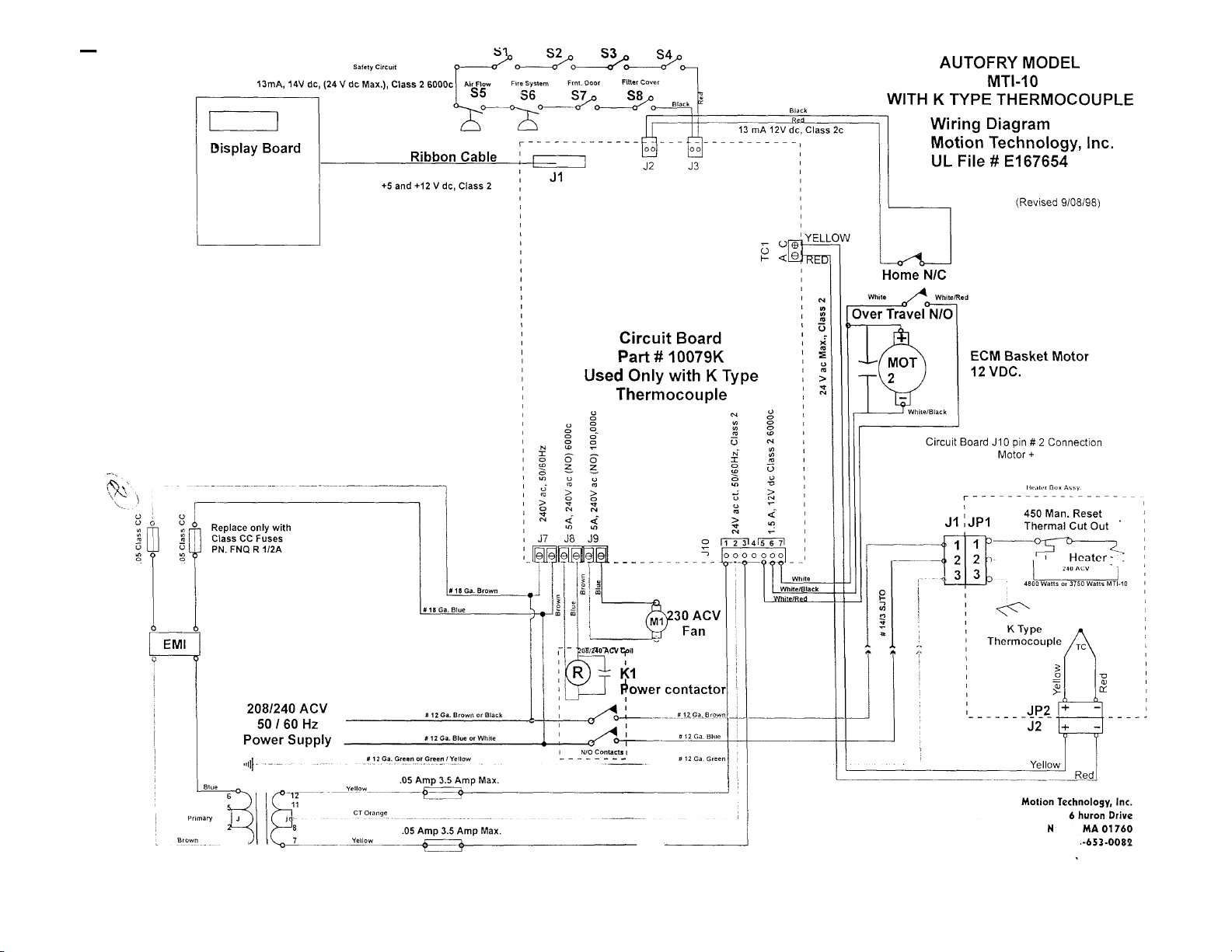
AUTOFRY Model MTI-10 Thermocouple Circuit Thermocouple Circuit
System Overview
The "K" type thermocouple is the junction formed by joining two dissimilar metals. Proper alloy selection
results in a measurable and predictable voltage generated at that junction. This voltage when detected
by the circuit board will indicate actual oil temperature.
The circuit board regulates the electrical supply to the heater elements to maintain the oil
temperature.
The YELLOW wire is positive the RED wire is negative. Crossing these two wires will result in erroneous
temperature or an error code at the keypad display of Prb, A07orA08.

AUTOFRY Model MTI-10 Thermocouple Circuit
The thermocouple plug and its socket at the bottom of the heater box must be connected plus to plus
and minus to minus. Although the pins and sockets are two different sizes it is possible to force the
connections together backwards. Always check this connection.
The probe itself is connected with in the heater box assembly. This is a simple two-wire connection.
Ensure that the YELLOW lead is connected to the + terminal of the socket and the RED lead is
connected to the - terminal. If connected backward oil tempeture will read 761 or the display at the
keypad will read A07 or Prb.

AUTOFRY Model MTI-10 Thermocouple Circuit
Trouble Shooting
A07 at keypad display (A07 is a frequency
conflict error)
• Crossed wires at heater box.
• Crossed wires at circuit board.
Prb at keypad display. (Prb is an error for
an open probe)
• Plug not installed at heater box.
• Connections not made at circuit board.
• Loose solder connection at TC1 terminal on circuit board.
Temperature reading of 761 at keypad display.
• Plug not installed at heater box.
• Short in thermocouple.
• Short in thermocouple wiring.
• Plug installed backwards at heater box.
• Crossed wire at heater box.
• Crossed wiring at circuit board.
A08 at keypad display.
(A08 is a temperature difference registered by the controller of 50 deg. In 5
seconds.)
• Check oil level in oil vat.
• Check all connections.

AUTOFRY Models FFG-10 and MTI-10 Fan Circuit Fan
Circuit Overview:
The fan circuit is comprised of the following components,
1. The 240 AC Volt Fan (part no. 10089)
2. The Circuit Board ( part no. 10079 or 10079K)
3. 2 Wire Assemblies,
• # 18 Gage Blue (part no. 6-10)
• # 18 Gage Brown (part no. 7-10)
The fan functions to continuously filter the air from the cook chamber through the filters
and exhaust it out through the top of the AUTOFRY.
Trouble Shooting:
1. Turn unit on, fan runs for 10-12 seconds then shuts off or display reads Sft.
• Safety related problem, see safety circuit trouble shooting.
2. Fans operated but at very low RPM.
• Unit supply voltage too low. Verify it is at least 200V AC.
• Fan is blocked with oil or other materials, remove stack cover and filters then
clear fan.
• Fan is starting to fail, replace fan.
3. Fan operated but there is no exhaust from top of unit.
• Louvers in the stack cover have closed. Remove stack-cover and open louver.
• Check fan airflow direction.

AUTOFRY Models FFG-10 and MTI-10 Fan Circuit
4. Fan does not operate at all.
• Fan has burned out.
• On board fuses (part No. 10079 Only) have blow.
• Fan relay on board has frozen.
• Branch Circuit Fuses Blown.
Inspecting and Testing:
CAUTION:
The exhaust fan operates on 220 volts. Ensure that caution in used when working on
the fan circuit.
Remove the
stack cover at the
top of the
AUTOFRY.
Inspect the
louvers to ensure
that they are
open. If they are
closed or if the
fusible link has
broken, it will
need to be
repaired.
Remove any and all debris that may
be accumulated in the fan.
Inspect the condition of the fan and
it's wire terminations. Reconnect any
loose wires.
Check the voltage at the fan
terminals there should be line
voltage, however the fan draws only
.1 amp.
Spin the fan blades to ensure the fan
is not bound.

AUTOFRY Models FFG-10 and MTI-10 Fan Circuit
At the circuit board (Part # 10079):

AUTOFRY Model MTI-40 Fan Circuit
For MTI-40 models with serial numbers of 1110-40 and lower the fan circuit will consist of one
240 V ac exhaust blower located at the top of the fryer filter chamber after the last filter and
below the fire damper assembly. To access this blower remove the fire damper cover. There
may also be two small 240 V ac cooling fans located in the rear electrical section. These fans
function to cool the electronic controls. All fans are wired in series into the last two terminals at
M4 or J9 located at the bottom left corner of the circuit boards.
For models with serial numbers 1111-40 thru 1141-40 there are three 240 V ac exhaust blowers
used within the filter chamber. There are no cooling fans used for the electrical chamber, as
there is more than adequate ventilation in these models.
For models with serial numbers 1142-40 and higher there is a single 240V ac exhaust blower
within the filter chamber. Again no cooling fans are used in these models.

AUTOFRY Model MTI-40 Fan Circuit
For models with serial numbers 1111-40 and higher accessing the exhaust blower(s) is done by
removing the top panel from the AUTOFRY. After removing the top panel lift out the fire damper. The fire
damper is safety interlocked and must be replaced in order for the appliance to heat.
As with all AUTOFRY models the fan circuit is programmed to start when the ON button at the keypad is
pushed and shuts off when oil temperature falls to below 150° F. Additionally if the thermocouple is not
connected to the circuit board the fan will run continuously.

AUTOFRY Models FFG-10 and MTI-10 Key Pad Circuit
Key Pad Circuit Over-View:
Figure 1 - Key Pad Circuit
The keypad circuit is comprised of 3 parts
1. The key pad (part no. 10051 and 10051K)
2. The ribbon cable (part no. 10050 and 10050K)
3. The circuit board (part no.10079 10079K)
The keypad, located at the front of the AUTOFRY, is linked to the circuit board, located in
the rear of the AUTOFRY, via a 24 "or 36" ribbon cable. This cable runs through a conduit
tube that is visible at the interior of the cook chamber.
The keypad is the user interface to the functions of the fryer. As such it is exposed to
grease, chemicals and constant abuse.

AUTOFRY Models FFG-10 and MTI-10 Key Pad Circuit
Key Pad Functions
ON
Press the ON key to begin heating the
oil. OFF
Press the OFF key to shut the
AUTOFRY off. COUNT
Press the count key to view the number
of completed cook cycles. STAND-BY
Press the Stand-by key to place the
AUTOFRY in the Stand-by mode
(Stand-by LED Illuminates). For
controller with RTD, Press the Stand-by
key a second time to exit the stand-by
mode. For controller with thermocouple
press clear to exit stand-by mode.
Stand-by LED will go out.
START
The start key will begin the cook cycle and count down.
WAIT LED will illuminate during the cook cycle and any time oil temperature falls
below 300-340 Deg. F.
CLEAR
Press the clear key to clear or cancel any cook time or cook cycle.
READY LED (Light)
The ready light will illuminate at 300° F for controller with RTD and at 340 for
controller with thermocouple
WAIT LED (Light)
The Wait light will illuminate during heat up and during a cook cycle.
STAND-BY LED (Light)
The Stand-by light illuminates during the stand-by mode.
NOTE:
If power is interrupted while the AUTOFRY is in the Stand-by mode the Stand-by function
may remain active even though the Stand-by light is not illuminated. In this case simply
press the Stand-by key.

AUTOFRY Models FFG-10 and MTI-10 Key Pad Circuit
Cook times for the controller with a thermocouple (10079K).
The maximum cook time is 15 min. and 59 sec.; however, the display is limited to
three digits.
For cook times of 10 Min the display will read the letter A followed by the
seconds.
For 11 Min. the letter b (the B is in lower case so that it is not confused with the
number 8)
For 12 Min. the letter C
For 13 Min. the letter D
For 14 Min. the letter E
For 15 Min. the letter F
The display will count down through these letters until time remaining is 3 digits or less.
Minutes are separated from seconds with a colon.

AUTOFRY Models FFG-10 and MTI-10 Key Pad Circuit
Trouble shooting:
1. No display.
• Check cable connections
• Short in display
2. Ready, Wait or Stand-by LED does not work.
• LED cracked or damaged.
• Short in circuit
3. One row of keys does not work.
• Short circuit
• Loose ribbon cable.
• Worn switch membrane.

AUTOFRY Models FFG-10 and MTI-10 Key Pad Circuit
Test the new keypad
NOTE:
In some isolated cases there is an excess of RFI (Radio Frequency Interference) or EMI
(Electromagnetic Interference) this can cause some intermittent display shut downs. There may
be a need for a stronger EMI filter this can be special ordered. This condition exists very
infrequently; however, it is helpful to know.

AUTOFRY Models FFG-10 and MTI-10 Heater Circuit
Heater Circuit Overview
Figure 1 - Heater Circuit
The Heater circuit is comprised of the following components
1. MDR (Mercury Displacement Relay/ Power Contactor).
2. High Limit Thermostat.
3. Heater Element ( 208 or 240 ACV 3750 Watts or 240 Volt 4800 Watt or 208 Volt
4160 Watt).
Power is supplied to the heater element in the following way,
The Circuit Board receives oil temperature readings from the RTD (Resistance Temperature
Detector) or the "K" Type thermocouple, if the oil temperature is below 354°F the coil at the
MDR will be energize and the contacts of the MDR will be closed to deliver line voltage to the
heater element. When oil temperature reaches 354°F the coil de-energizes and the contacts will
open.

AUTOFRY Models FFG-10 and MTI-10 Heater Circuit
If the safety circuit is open the MDR coil will not energize. The safeties MUST be closed in order
for the coil to energize. It is possible to by-pass the safeties for the purpose of testing only. In
the upper right hand corner at the circuit board locate the two pin plug at positions # 8 & #9 for
part No. 10079 or position J3 for part No. 10079K (the plug nearest the rear of the AUTOFRY.).
There is one red and one black wire connected to this plug, there also may be a second plug
with an orange or yellow wire loop ("jumper") hanging loose at this position. Remove the plug
and insert the jumper in its place.
If there is no jumper simple remove the red and black wire and form a loop with any conductible
wire, then re-insert the plug into the socket. (See figure 2)
If the RTD or Thermocouple circuit is shorted or open (417 or Prb Error Code) the MDR coil will
not energize. This circuit is critical to the operations of the AUTOFRY and must be intact at all
times.
If the coil of the MDR remains energized for 16 min. and 49 sec. the circuit board will deenergize the coil of the MDR and an error of A05 will be displayed at the keypad.

AUTOFRY Models FFG-10 and MTI-10 Heater Circuit
Figure 3 shows the interior view of a typical heater box assembly.
There are 6 components within the heater box assembly they are...
1. The Heater Element.
• Part # 10059-A is 240 Volt, 3750 Watt.
• Part # 10059 is 208 Volt, 3750 Watt.
• Part # 10059-D is 240 Volt 4800 Watt
• Part # 10059-E is 208 Volt 4160 Watt
2. The Probe.
• RTD Part #10065.
• Thermocouple Part # 10K-Couple
3. The High Limit Thermostat.
• Part #10066
4. The Heater IEC Socket
• Part #10063
5. The Probe Socket.
• RTD IEC Socket Part # 10062
• Thermocouple Socket Part # SPJ-K-F
6. 4 Wire Assemblies.
• Part # 10-24 (12 Ga. Blue) Heater Socket to Element
• Part # 10-22 (12 Ga. Brown) Heater Socket to High Limit
• Part # 10-23 (12 Ga. Green) Heater Socket to Ground
• Part #10-21 (12 Ga. Brown) High Limit to Element
Figure 3 - Heater Box Interior View

AUTOFRY Models FFG-10 and MTI-10 Heater Circuit
Note that the RTD leads (Red and White) are placed as far from any voltage carrying wires as
possible. Also note that the high limit capillary tube must be arranged so as not to make contact
with the heater element stud. A small kink should be made in the capillary tube so that if it is
pulled from the front of the heater box it will not inadvertently make contact with the heater stud.
The heater elements are case specific, Check the Equipment Identification tag to match voltage,
wattage and amperage.
Trouble Shooting A05 or a no heat condition:
1. Re-set the high limit thermostat.
The re-set is located at the bottom of the heater box assembly (small red button). It is
sometimes difficult to access with your fingers, if so the eraser end of a pencil is helpful.
When re-set there will be a slight "Click" the button will not stay in the up position.
Note: The limit needs to cool to 50 °F below its preset before it can be re-set.
Replace the limit switch if it continues to trip.
2. Allow the oil temperature to "recover".
During busy periods product should be cooked in advance and placed in a warming
station.
3. Low voltage supply.
The AUTOFRY can operate on as little as 190 Volts; however, it will not efficiently
heat the oil. Verify the line voltage.
4. Low amperage.
Ensure that the circuit is dedicated and grounded.
5. Fouled and grease laden plugs and sockets This will impede the heater circuit.
6. Check for any break in the heater circuit. Inspect all wiring, cables and splices.
7. A failure in the RTD or Thermocouple circuit could transmit a false
temperature. Inspect the RTD or Thermocouple circuit. (See RTD or Thermocouple Trouble
Shooting, Testing and Installation)
8. Test the heater element for resistance.
Though highly unlikely, the element may be defective, however if the AUTOFRY has been run
dry for an extended period of time the element may burn out.
9. Inspect the circuit board for visible scorching or loose connections Replace if necessary.

AUTOFRY Models FFG-10 and MTI-10 Heater Circuit
Inspecting and Testing Procedure:
Disconnect the AUTOFRY from main power.
Verify the line voltage.
The AUTOFRY will give the appearance of operating if connected to 115 -120 ACV,
however, the fan will operate slowly and the heater will not be able to heat the oil.
There will be a display at the keypad.
By-pass or "Jump" the safety circuit.
This will eliminate any safety-related problem.
Inspect all wiring to and from the MDR.
Inspect the circuit board connections.
Visually inspect the circuit board for damage or burned or scorched components.
Inspect the heater plug and cable for excessive grease build up and for any
visual damage.
Remove the wire food basket from the cook chamber.
Removing the wire food basket will ease access to the oil pot and heater box
assembly.
Ensure that the oil pot is filled to the cold fill line (approximately 2" below the top
edge of the pot).
Test the heater box assembly for continuity at the heater I EC socket.
(See figure-4)

AUTOFRY Models FFG-10 and MTI-10 Heater Circuit
Clean the IEC socket of any and all accumulated oil.
Inspect the interior of the heater box for shorted, loose or damaged wires and
connections.
Check for any signs of immersion and dry all connections as necessary.
Re-set the high limit.
Install the heater box onto the oil pot.
Plug the RTD or Thermocouple plug into its socket at the bottom of the heater
box assembly.
Install meter probes into the heater plug line and neutral connections.
Set meter to ACV.
Plug the AUTOFRYinto main power.
The fan will come on.
The MDR will energize.
There will be line voltage at the heater plug.
After 12 seconds there should be a display at the keypad of current oil
temperature.
Re-connect the heater plug to the heater box and verify that the oil is heating.
Allow the oil to reach it's ready temp. and verify that the MDR coil de-energizes.
Perform a few cook cycles.
Re-install the wire food basket and live test the AUTOFRY with product to ensure
the unit functions.
Return the safety circuit to its normal operating mode and re-start the AUTOFRY.

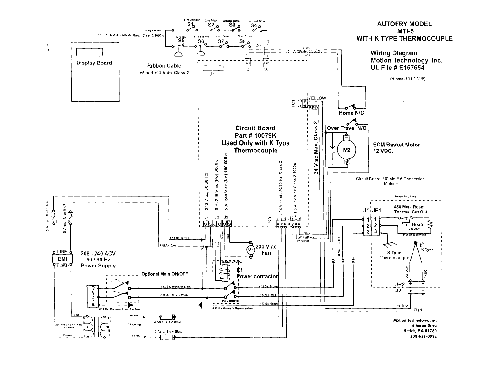
AUTOFRY Model MTI-5 Heater Circuit Overview:
The MTI-5 heater circuit operated in the same manner as the MTI-10 and MTI-40 models
to heat the oil. The only substantial differences are, Element Wattages. Heater Box
Mounting. Heater Box Configuration.
NOTE: There is a Main ON/OFF switch on the right side of the Model MTI-5.
Ensure this switch is in the marked ON position.
MTI-5 Heater Circuit Wiring Diagram
Main power through the
ON/OFF switch is
connected to the MDR or
Power Contactor. The
thermocouple circuit,
controlled at the circuit
board, reads oil
temperature and will
energize the contactor coil
to close the contacts and
supply line voltage to the
heater.
The Set-point is 352° F
MAX. There for any time
oil temperature is below
354° The contacts and coil
will be energized to supply
the heater.
The safety circuit and
thermocouple circuit
must be closed in order
for this circuit to operate.
The manual re-set limit must - also be closed for this circuit to operate.

Error Codes:
A05: Oil temperature has not reached set point with in 16 min. 49 sec.
Troubleshoot:
Low voltage: Check supply voltage.
Dead leg: Check power supply voltage ground to line & ground to neutral. Check
main ON/OFF switch.
High limit tripped: Re-set limit by pressing red button at the bottom of the heater
box.
Heater box not firmly seated on the platform: Re-seat heater box.
Heater plug has slipped down: Loosen clamp and push plug up until a solid
contact is made tighten clamp.
Loose wiring: Check all wiring in the heater box.
Loose wiring: Check all wiring from the contactor to the heater supply plug.
A07: Frequency Conflict
Troubleshoot:
Check harmonization of Thermocouple leads. Yellow to Yellow and Red to Red
at the thermocouple plug and socket.
Ensure that thermocouple wiring at circuit board is yellow to top terminal and red
to lower terminal.
Check thermocouple extension lead for short or break.
A 08: Temperature difference of 50 degrees in 5 second.
Troubleshoot:
Check oil level. Press OFF at keypad then
re-start.
Prb: Open thermocouple circuit.
Troubleshoot:
Check wiring.
Check thermocouple extension lead for short or break.
Check that heater box is firmly seated.
Check probe. Replace if defective.

Testing the Heater Circuit:
After checking for main power and that the main ON /OFF switch is on press the high limit
re-set, this may be the only problem. If this does not fix the problem perform a continuity
test across the heater socket prongs. If there is no continuity open the heater box and test
and inspect the wiring, high limit and heater element. Replace parts as necessary.
If the heater box assembly checks out in good working condition the follow these steps.
The first step will be to jump the safety circuit, after installing the jumper at J3
remove the basket, oil pot and heater box.
Install a thermocouple simulator to the thermocouple plug and set it at any
temperature below 350° F this will allow the heater circuit to energize.
Install a meter set at AC Volts into the heater supply plug.
Press the start button at the keypad.
There should be line voltage at the heater plug if there is not you will need to
trace the heater line back as far as necessary to find the interruption of power.
If there is power at the plug but when installed, the heater does not heat, check that the
plug and the socket make secure contact.
Live test the AUTOFRY to ensure that the heater heats. Then remove the jumper from J3,
re-install the safety circuit and all panels.

AUTOFRY Model MTI-5 Heater Circuit
Addendum to the TSM
AUTOFRY Model MTI-5 Heater Circuit Overview:
The MTI-5 heater circuit operated in the same manner as the MTI-10 and MTl-40 models to
heat the oil. The only substantial differences are, Element Wattages. Heater Box Mounting.
Heater Box Configuration.
NOTE: There is a Main ON/OFF switch on the right side of the Model MTI-5. Ensure this
switch is in the marked ON position.
MTI-5 Heater Circuit Wiring Diagram
Main power through the ON/OFF switch is connected to the MDR or Power Contactor.
The thermocouple circuit, controlled at the circuit board, reads oil temperature and will
energize the contactor
coil to close the contacts
and supply line voltage to
the heater.
The Set-point is 352° F
MAX. There for any time
oil temperature is below
354° The contacts and
coil will be energized to
supply the heater.
The safety circuit and
thermocouple circuit
must be closed in order
for this circuit to operate.
The manual re-set limit
must also be closed for
this circuit to operate.

AUTOFRY Model MTI-5 Heater Circuit
Addendum to the TSM
Heater Platform and Plugs:
of the AUTOFRY and from the rear of the AUTOFRY
by removing the rear access panel.
The heater
box
assembly
mounts in the
AUTOFRY
on a
platform that
has the fixed
mounted
heater supply
plug and the
thermocouple
plug.
Access to the
wiring for this
platform can
be made by
removing the
small
access panel
at the left side
The heater plug and
cord assembly is
secured into place
with a clamp that is
screwed through the
platform. It is
possible for this
clamp to loosen and
the resulting in poor
contact or no contact
between the plug
and the socket on
the bottom of the
heater box assembly
resulting in a no heat
or sporadic heating
condition.

AUTOFRY Model MTI-5 Heater Circuit
Addendum to the TSM
Heater Box Assembly:

AUTOFRY Model MTI-5 Heater Circuit
Addendum to the TSM
Error Codes:
A05: OH temperature has not reached set point with in 16 min. 49 sec.
Troubleshoot:
Low voltage: Check supply voltage.
Dead leg: Check power supply voltage ground to line & ground to neutral. Check
main ON/OFF switch.
High limit tripped: Re-set limit by pressing red button at the bottom of the heater
box.
Heater box not firmly seated on the platform: Re-seat heater box.
Heater plug has slipped down: Loosen clamp and push plug up until a solid
contact is made tighten clamp.
Loose wiring: Check all wiring in the heater box.
Loose wiring: Check all wiring from the contactor to the heater supply plug.
A07: Frequency Conflict
Troubleshoot:
Check harmonization of Thermocouple leads. Yellow to Yellow and Red to Red
at the thermocouple plug and socket.
Ensure that thermocouple wiring at circuit board is yellow to top terminal and red
to lower terminal.
Check thermocouple extension lead for short or break.
A08: Temperature difference of 50 degrees in 5 second.
Troubleshoot:
Check oil level. Press OFF at keypad then
re-start.
Prb: Open thermocouple circuit.
Troubleshoot:
Check wiring.
Check thermocouple extension lead for short or break.
Check that heater box is firmly seated.
Check probe. Replace if defective.

AUTOFRY Model MTI-5 Heater Circuit
Addendum to the TSM
Testing the Heater Circuit:
After checking for main power and that the main ON /OFF switch is on press the high limit
re-set, this may be the only problem. If this does not fix the problem perform a continuity
test across the heater socket prongs. If there is no continuity open the heater box and test
and inspect the wiring, high limit and heater element. Replace parts as necessary.
If the heater box assembly checks out in good working condition the follow these steps.
The first step will be to jump the safety circuit, after installing the jumper at J3
remove the basket, oil pot and heater box.
Install a thermocouple simulator to the thermocouple plug and set it at any
temperature below 350° F this will allow the heater circuit to energize.
Install a meter set at AC Volts into the heater supply plug.
Press the start button at the keypad.
There should be line voltage at the heater plug if there is not you will need to
trace the heater line back as far as necessary to find the interruption of power.
If there is power at the plug but when installed, the heater does not heat, check that the
plug and the socket make secure contact.
Live test the AUTOFRY to ensure that the heater heats. Then remove the jumper from J3,
re-install the safety circuit and all panels.

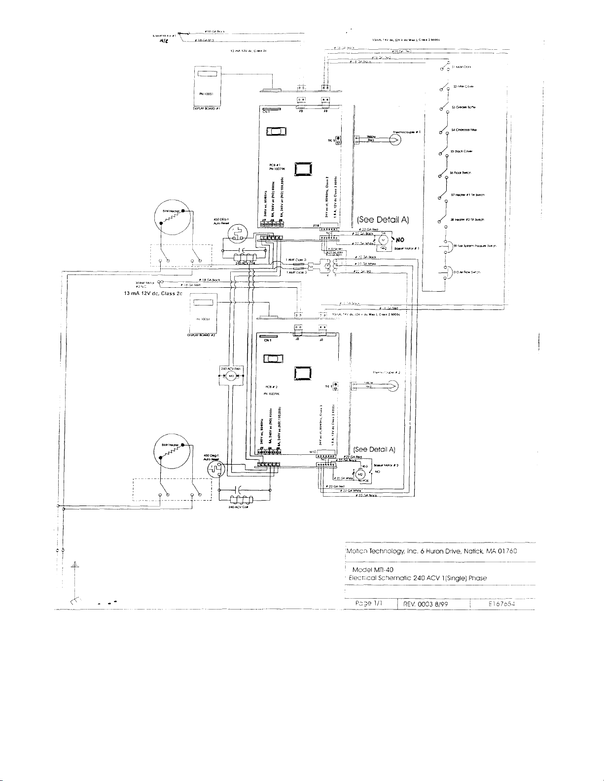
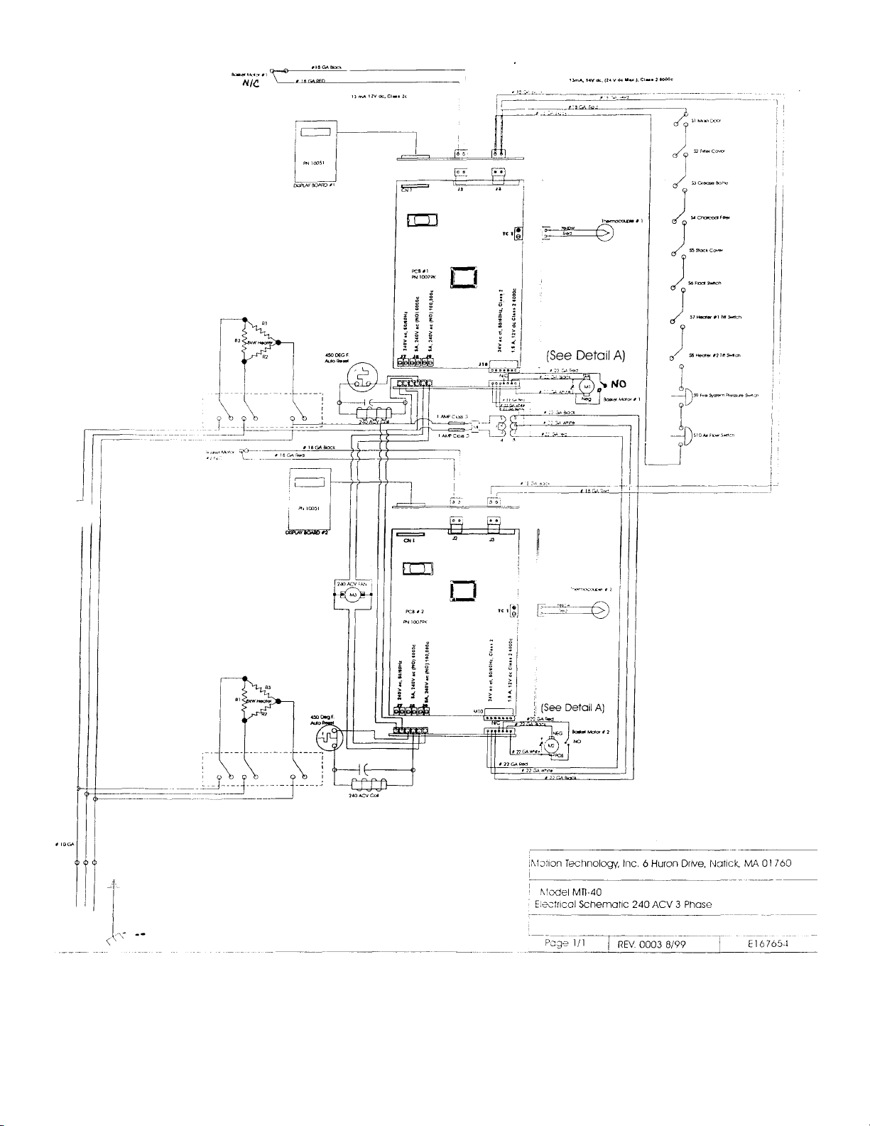
AUTOFRY Model MTI-40 Heater Circuit
The model MTI-40 Electric AUTOFRY is manufactures in either 240 Volt three-phase or
240 Volt AC single-phase, (consult the ID tag located at the left side of the appliance for
specific ratings).
Figure - 1 MTI-40 Single - Phase wiring

AUTOFRY Model MTI-40 Heater Circuit

AUTOFRY Model MTI-40 Heater Circuit
Models with serial numbers 1110-40 and lower
be lifted out of the oil vat. These heater assemblies are equipped with a mercury tilt switch that will deenergize the contactor coil when the element is lifted out of the oil vat.
The high limit used in these models is a manual re-set rated at 450° F. Unlike the models MTI-5 and
MTI-10 the high limit is wired at the coil of the power contactor and not directly in line with main power,
this is due to electrical ratings. The capillary bulb is fixed in place through a bulkhead fitting in the oil
vat. The re-set for this limit is located inside the main door at a panel just below the oil vat. Also
located on this panel in the oil pump on off switch.
use a heater pivot bracket that allows the elements to
Figure - 3 MTI-40 Heater Pivot Bracket Assembly
(Serial Numbers 1110-40 and Lower)

AUTOFRY Model MTI-40 Heater Circuit
For MTI-40E models, serial numbers 1111-40 and higher, the heater elements are mounted
directly to the oil pot deck and do not pivot out of the oil. The high limit is a 450° F automatic reset type. The capillary tube, mounted to the element bars, is held in place with a bracket that
wraps around the elements bars. There must be some allowance for play in the capillary tube to
prevent the tube from breaking as the element flexes during operation.
Figure - 4 MTI-40 Heater and High Limit Mounting
(Serial Numbers 1111 -40 and Higher)

AUTOFRY Model MTI-40 Heater Circuit
Each element housing consists of three separate resistors, although it is possible
for the MTI-40 to heat with one or more bad resistors efficiency will be
compromised.
To trouble shoot a bad resistor begin by verifying amperage draw.
1. With 6000-watt elements (12000-watts total) at 240 Vac Single-phase
the amperage draw should be 50.00 (+/-).
2. With 6000-watt elements (12000-watts total) at 240 Vac Three-phase
the amperage draw should total 28.90 (+/-).
3. With 8000-watt elements (16000-watts total) at 240 Vac Single-phase
the amperage draw should total 66.66 (+/-).
4. With 8000-watt elements (16000-watts total) at 240 Vac Three-phase
the amperage draw should total 38.53 (+/-).
Using a test meter check across each of the element resistor leads to locate any
dead resistor then replace the elements if necessary. Replacement of the entire
pivot bracket assembly is suggested for models equipped with that part.
The automatic re-set limit thermostats will trip at 450°F and re-set after cooling
50° F. Coil voltage at the power contactor will be de-energized if the limit has
tripped.
Nuisance trips can be caused by a limit that is in too close contact with the
element sheaths. If this is the case, simply move the capillary tube off the
element, however, NEVER remove the limits from the circuit. Excessive build up
Any open safety will de-energize the heater coils at the power contactors. This
should not be confused with an open high limit or a failed heater. An open safety
will be displayed at the keypad as Sft. Were as if the AUTOFRY does not reach
its ready temperature with-in 16 minutes and 49 seconds the display at the
keypad will be A05.

AUTOFRY Model MTI-40 Phase Conversion Instructions
MTI-40 Three Phase to Single Phase Conversion
Parts Required
Single Phase Power Contactors
I.D. Plate with Serial Number
Electrical service will need to be changed. The single-phase requirements are
240 V ac Dedicated Grounded Circuit. 50 Amps with 2-6kW elements, 67 Amps
with 2-8 kW elements.
Instructions:
1. Disconnect the AUTOFRY from Main Power.
2. Remove the rear access panel.
3. Disconnect the heater leads from the bottom terminals of the power contactors
4. Disconnect the coil leads from the power contactors
5. Disconnect the power supply leads from the top terminals of the power contactors
6. Remove the three-phase power contactors
7. Remove the RED leads from the main terminal block
8. Remove the NEMA 15-50 Plug Cap from the main power cord.
9. Cut-back the RED wire from the supply cord so that it will not be accidentally
connected or...
10. Install a new three-wire supply cord for hard wire hook-up.

AUTOFRY Model MTI-40 Phase Conversion Instructions
Figure 1 - Three Phase Contactor Preparation for Single-Phase
conversion:
Separate the element led wires. With a meter locate and mark the resistor leads
as shown in Figure 2 below. Each heater has three elements resistors there are
six wires total for each heater.
Figure 2 shows the wiring diagram for both the three-phase and the single-phase
models

AUTOFRY Model MTI-40 Phase Conversion Instructions
Make the conversion:
1. Install the new single-phase power contactors.
2. Attach the separated heater leads to the Bottom poles
of the contactors.
3. Re-attach the coil leads to the single-phase contactors.
4. Attach the power supply (White or Blue and Black or Brown wires) to the Top of the
single-phase contactors.
5. If Necessary: Install the new power supply to the terminal block.
Figure 3 - Single Phase Contactor

AUTOFRY Model MTI-40 Phase Conversion Instructions
To convert the MTI-40 from single-phase to three-phase follow these instructions.
This conversion will require the following parts;
Two three-phase power contactors
Three-phase terminal block to contactor wire assembly.
I.D tag with serial number.
4-Wire 6' power-supply cord with NEMA 15-50 Plug.
1. Disconnect the AUTOFRY from Main Power.
2. Remove the rear access panel.
3. Disconnect the heater leads from the bottom terminals of the power contactors
4. Disconnect the coil leads from the power contactors
5. Disconnect the power supply leads from the bottom terminals of the power
contactors
6. Remove the single-phase power contactors
7. Remove the power supply cord and replace it with the new 4-wire cord and plug.
8. Install the red terminal block to power contactor wire assembly securing it in place
with the existing wire harness cable clamps.

AUTOFRY Model MTI-40 Phase Conversion Instructions
With a meter locate and mark the element resistor leads as shown below and connect them to the
new three-phase power contactor as shown in the wiring diagram below.

AUTOFRY Model MTI-40 Phase Conversion Instructions
Make the conversion
1. Install the new three-phase power contactor, note the arrow locations
indicating UP.
2. Connect the element resistor leads as follows, R11 to R32, R21 to R12 and
R31 to R22. (see figure 5 and figure 6) then connect each set of leads to the
bottom terminals at the three-phase power contactor.
3. Re attach the coil leads to the three-phase contactors
4. Attach the power supply leads including the new red leads to the top
terminals of the contactor.
5. Install the new power supply cord and plug to the terminal block. Ensure
that the green ground wire is securely attached to the appliance chassis.

INSTALLATION OF HIGH LIMIT BRACKET ON THE MTI-40
REQUIRED PARTS AND TOOLS
• High Limit Bracket
• Phillips Head Screwdriver
• Pliers
PROCEDURE
1. Make sure the AUTOFRY is turned off and the oil is cool
2. Remove the HEATER ELEMENT from the AUTOFRY. Wipe off any excess oil
from the Heater Element.
3. Using a Phillips Head Screwdriver, unscrew and remove the METAL BAND that
holds the High Limit Probe to the Heater Element. Dispose of the metal band and
screw.
4. Using your fingers, bend the HIGH LIMIT wire up so it is out of the way. Your
Heater Element should appear as in Figure 1.
Figure 1
5. Place the HIGH LIMIT BRACKET around the Heater Element Bar (see Fig.2)

Figure 2
6. Using you fingers, bend ONE ARM of the High Limit Bracket over the Heater
Element Bar (see Fig. 3).
Figure 3
7. Using the pliers, squeeze the ARM of the High Limit Bracket so That it is tight
around the Heater Element Bar (see Fig 4).

Figure 4
8. Repeat steps 6 and 7 with the OTHER ARM of the High Limit Bracket. When you
are finished, the Bracket should appear as in Figure 5.
9. Using your fingers, guide the HIGH LIMIT tube through the holes of the High Limit
bracket. When you are finished, it should appear as in Figure 6.

10. The procedure is complete. Put the Heater Element Box back into the
AUTOFRY. You are now ready to begin cooking.

AUTOFRY Models FFG-10 and MTI-10 Branch Circuit
Branch Circuit Overview:
Figure 1 - Branch Circuit Overview
The branch circuit is the power supply for the circuit board. It is comprised of the following
components.
1. Power supply from the MDR ( Mercury Displacement Relay)
2. The Transformer 240 ACV Primary and 24 ACV CT (Center Tapped) Secondary.
3. An EMI (Electromagnetic Interference) Filter
4. 2, Class CC 1/2 amp. ACV fuses and their holders (primary side).
5. 2, 3 amp glass fuses (secondary side).
6. Models FFG-10 will utilize 1/2 amp circuit breakers these may be mounted
externally or internally depending of the date of manufacture. These breakers, if
defective, should be replaced.
Fuses on the primary side of the transformer must be replaced with exact
replacements.
Symptoms of Fuse Failure:
No audible tone from the circuit board when the AUTOFRY is connected to main power.

AUTOFRY Models FFG-10 and MTI-10 Branch Circuit
No response at the circuit board and or keypad when the ON key at the key pad is pressed.
No response from the exhaust fan.
Inspect the following:
Remove the caps from the fuse holders, remove the fuses and check them, with a meter, for
continuity.
• If the fuses fail replace them with similar parts.
Verify continuity from the power plug to the MDR (Mercury Displacement Relay) Verify that the
connections from the MDR to the transformer are made.
Inspect the soldered connections at both the primary and secondary sides of the transformer.

AUTOFRY Models FFG-10 and MTI-10 Branch Circuit
Check for line voltage at the following locations.
NOTE: With the exception RTD circuit all blue and brown wires should be carrying
line voltage.
1. At the MDR line in.
2. At the MDR line out to the transformer (# 18 GA. blue and Brown Wires).
3. At the transformer primary connections (#18 GA, Blue and Brown wires).
4. At both sides of the EMI filter (Line and Load).
5. At the fuse holder connections.
 Loading...