

Page 1

PC PRO
User manual
Page 2

PC PRO
User Manual
Part Number A37MAN
EN
Issue 1
© Autodiagnos 2010
Part Number A37MAN
EN - Issue 1
© Autodiagnos 2010
Page 3

Page 4

Contents
Quick reference guide
Introduction..................................... ... .... ................................................. 1
Product support hotline................ ... ... .... ... ... ... .... ... ... ... ........................... 2
Software CD ........................................................................................... 2
Hardware configuration .................................. .... ... ... ... ........................... 3
Configuring the PC ................................................................................. 4
Getting started........................................................................................ 6
Using Autodiagnos PC Pro....................................... ... ... .... ... ... ... ........... 8
Operating instructions
Overview............................................................................................... 10
Using Autodiagnos PC Pro....................................... ... ... .... ... ... ... .... ... .. 11
Troubleshooting.................................................................................... 23
Cable identification ............................................................................... 24
Licence Agreement
Licence Agreement for Autodiagnos PC Pro........................................ 27
Equipment disposal
Disposal of equipment.......................................................................... 29
Disposal of batteries............................................................................. 29
i
Page 5

Page 6
Quick reference guide
7
CR0239
1
5
6
2
4
3
Quick reference guide
Introduction
Congratulations on choosing the Autodiagnos PC Pro diagnostic system. The system
enables information to be extracted from various vehicle control modules when
connected via the vehicle’s diagnostic connector.
Both pre-EOBD (European On-Board Diagnostics) and EOBD-compliant vehicles are
covered.
Note: All post 2000 MY petrol cars and post 2004 MY diesel cars should conform to
the EOBD standard.
Overview
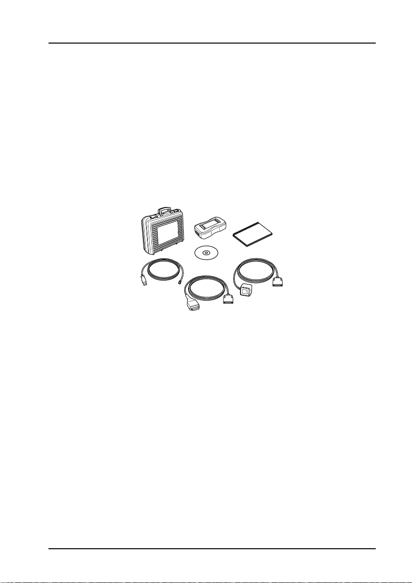
The kit includes the following items.
1. Carry case with foam insert.
2. Vehicle Interface.
3. USB cable.
4. J1962 OBD cable.
5. CD.
6. Quick reference guide.
7. Power supply unit.
1
Page 7

Quick reference guide
Product support hotline
Tel: +44 (0)844 665 7623.
Fax: +44 (0)844 665 7603.
Alternatively, visit the Autodiagnos website at www.autodiagnos.com.
Note: To avoid delay, always quote the serial number of the Vehicle Interface when
requesting support.
Software CD
Installation instructions
1. Insert the CD into the CD drive.
2. The installation on the CD should auto-run. If it fails to do so, navigate to the CD
drive in Windows Explorer and double-press the ‘Setup.exe’ icon.
3. Follow the on-screen instructions to install the application, accepting all options
provided to achieve the default installation.
4. Restart the PC before first use.
2
Page 8
Quick reference guide
4
3
1
Hardware configuration
Vehicle Interface (VI)
This component acts as an interface between the vehicle being tested and the
software installed on a PC.
Externally, the VI has a number of connectors, but no switches or buttons. It is
operated by the user from the PC screen.
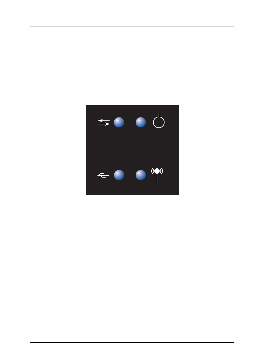
LEDs alert the user to the operational status of the VI.
AU0022
1. Communicating with vehicle systems.
2. Power.
3. USB connection status.
4. Bluetooth connection status.
1
3
222
4
3
Page 9
Quick reference guide
Configuring the PC
The PC must be set up to recognise the Vehicle Interface (VI). There are two methods
of connecting the VI:
• USB - Hard wired,
• Bluetooth - Wireless.
USB is the default connection method setting.
USB - Hard wired
Follow the procedure below to connect the PC to the Vehicle Interface (VI) using a
USB cable.
1. From the ‘VI Mode’ drop-down list on the ‘Settings’ tab, select ‘USB’.
2. Connect one end of a USB cable to the VI and the other end to a USB port on
the PC.
333
CR0236
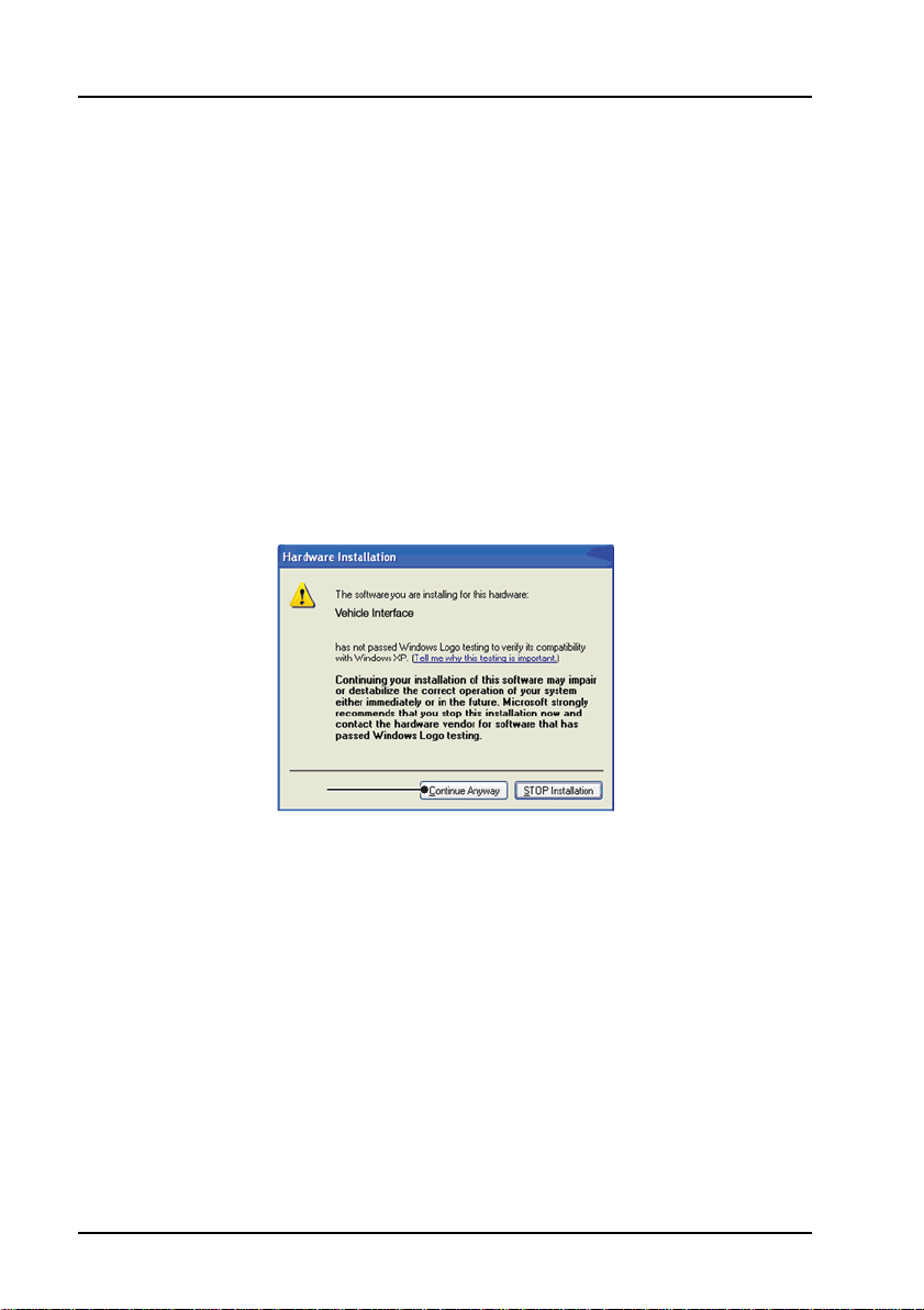
3. The drivers will install automatically. Press ‘Continue Anyway’ when prompted.
The operating system will display a notification when the process is complete.
Bluetooth - Wireless
Follow the procedure below to connect the PC to the Vehicle Interface using wireless.
1. Follow the instructions provided with your laptop or Bluetooth dongle to set up a
wireless connection to the Vehicle Interface. The Bluetooth device name is
‘Vehicle Interface’ and if requested enter the PIN code 1234.
2. Once the connection has been set up a COM port number will be displayed.
Make a note of this number.
3. From the ‘VI Mode’ drop-down list on the ‘Settings’ menu, select ‘Bluetooth’.
4. From the ‘Bluetooth Port’ drop-down list select the COM port number recorded in
step 2.
4
Page 10
Settings
3
2
4
5
Quick reference guide
111
2
3
AU0077
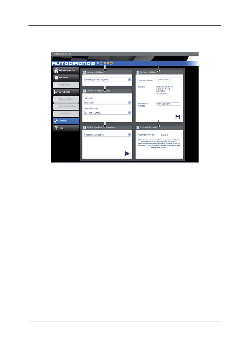
1. Language settings
2. Vehicle Interface (VI) settings
3. Vehicle Interface (VI) configuration
4. Company settings
5. Product information
From the ‘Settings’ screen, the software language can be selecte d. Please note the
Vehicle Interface (VI) must be connected to both the PC and a vehicle in order to
change the software language. This process may take up to twenty minutes.
The method of communication with the VI can also be changed. ‘USB’ is the default
communication method.
4
5
5
Page 11

Quick reference guide
CR0237
Getting started
Note: If the vehicle does not have a J1962 cable socket, the appropriate manufacturer
diagnostic cable will be required. See ‘Cable identification’, page 24.
USB Connection
1. Connect the EOBD cable to the Vehicle Interface.
2. Connect the appropriate manufacturer diagnostic cable if necessary to the EOBD
cable.
3. Connect the diagnostic cable to the vehicle’s diagnostic socket.
4. Connect the vehicle interface to the PC USB port.
5. Double-press the Autodiagnos PC Pro icon on the desktop to launch the
software.
6
Page 12
Quick reference guide
CR0238s
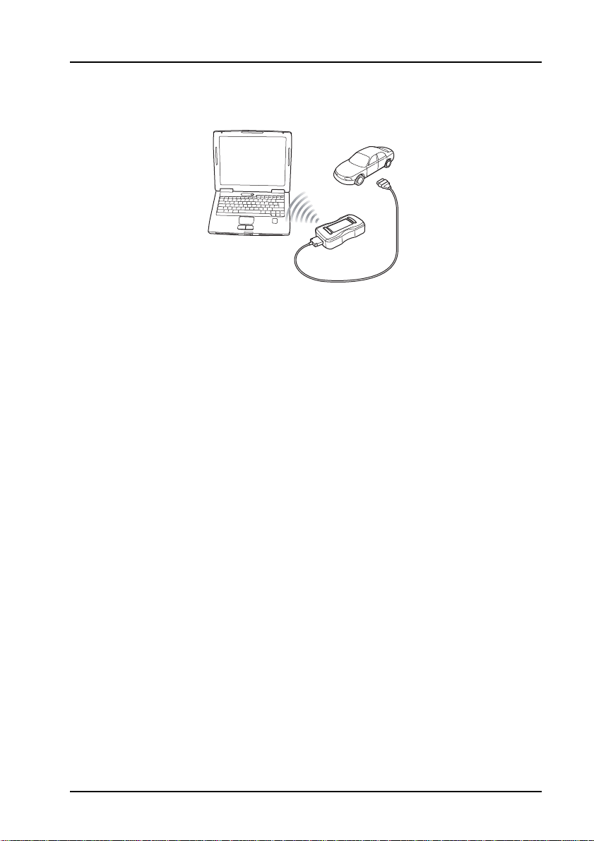
Bluetooth connection
1. Connect the EOBD cable to the Vehicle Interface.
2. Connect the appropriate manufacturer diagnostic cable if necessary to the EOBD
cable.
3. Connect the diagnostic cable to the vehicle’s diagnostic socket.
4. Double-press the Autodiagnos PC Pro icon on the desktop to launch the
software.
7
Page 13
Quick reference guide
666
55
2
11
33
44
77 88
AU0075
Using Autodiagnos PC Pro
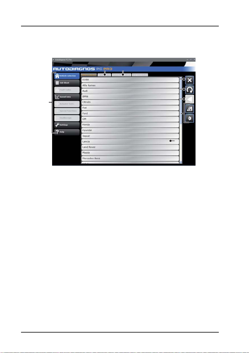
1. Menu items
2. Vehicle/System selection
3. Exit the application
4. Restart vehicle selection
5. Return to previous screen
6. View technical data (where installed)
7. View cable images
8. View connector locations
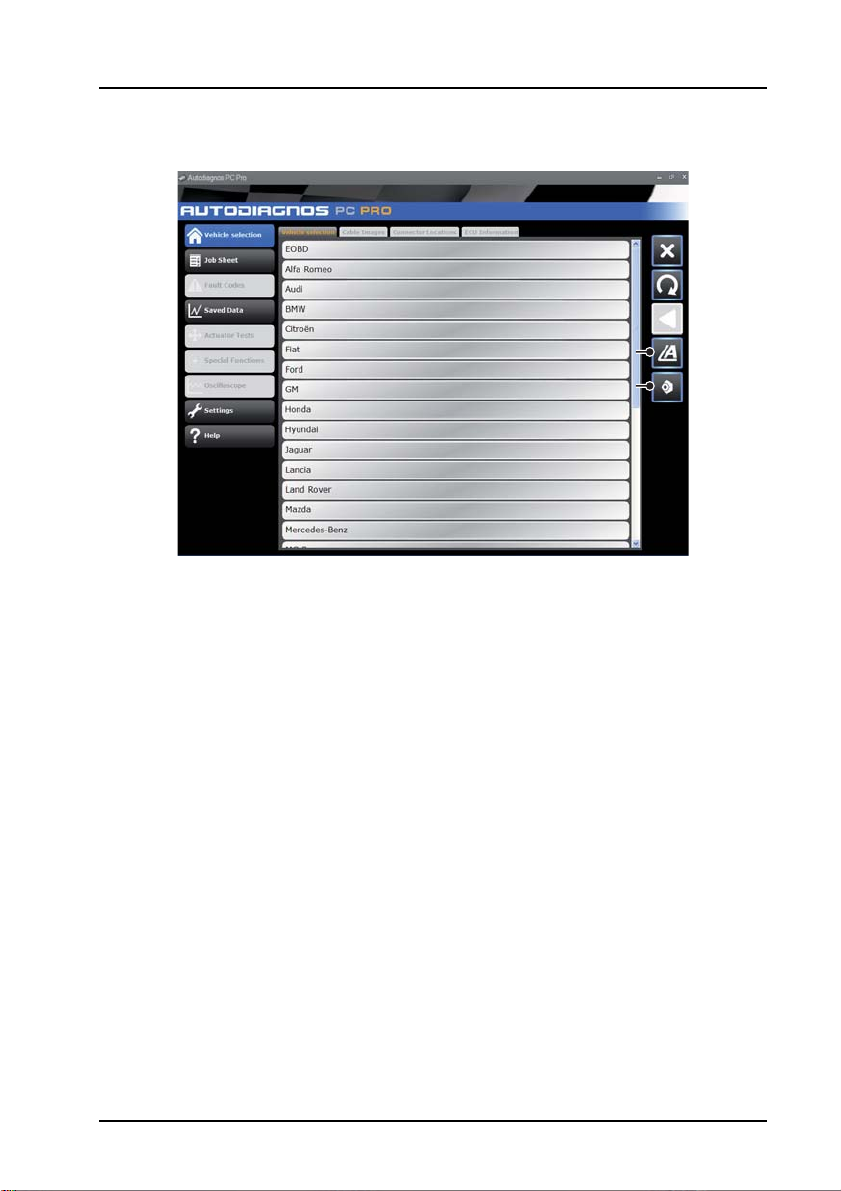
The ‘Vehicle Selection’ screen is displayed when Autodiagnos PC Pro is started.
Each screen has a number of icons and buttons which control the diagnostic
functions.
Diagnostic cable drawings and connector locations can be viewed by pressing button
7 or 8 respectively.
Note: All tabs, buttons and icons are highlighted when available for use.
8
Page 14
Quick reference guide
Starting a diagnostic session
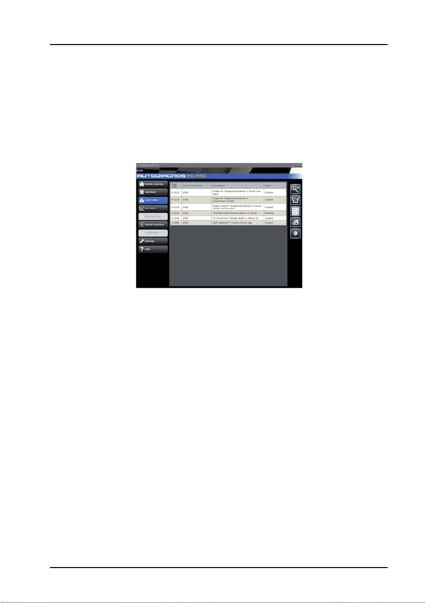
1. From the ‘Vehicle Selection’ screen, select the relevant vehicle and then system
for diagnosis.These options will appear over a number of consecutive screens.
2. Selecting a system will automatically prompt the software to begin
communication.
3. The communication LED on the Vehicle Interface will begin to flash, confirming
that the Autodiagnos PC Pro software is connecting to the system.
AU0073s
4. When the vehicle is ready for diagnostic tests, the diagnostic menu items on the
left hand side of the screen become enabled.
9
Page 15

Operating instructions
666
55
2
11
33
44
77 88
AU0075
Operating instructions
Overview
The screens have a number of icons and buttons which control the diagnostic
functions.
This guide explains the common controls and information screens.
In the graphic below, the ‘Vehicle Selection’ screen is selected.
Note: All tabs, buttons and icons are highlighted when available for use.
1. Menu items
2. Vehicle/System selection
3. Exit the application
4. Restart vehicle selection
5. Return to previous screen
6. View technical data
7. View cable images
8. View connector locations
10
Page 16
Operating instructions
666
55
2
11
33
44
77 88
AU0075
Using Autodiagnos PC Pro
Selecting a vehicle for testing
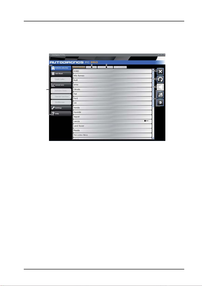
1. Menu items
2. Vehicle/System selection
3. Exit the application
4. Restart vehicle selection
5. Return to previous screen
6. View technical data
7. View cable images
8. View connector locations
From the ‘Vehicle Selection’ screen, select the relevant manufacturer, model and
then system for diagnosis. These options appear over a number of consecutive
screens.
Press button 2 to restart the vehicle selection and return to the list of vehicle
manufacturers.
Press button 1 to return to the previous screen.
Diagnostic cable drawings and connector locations can be viewed by pressing button
7 or 8 respectively.
Note: All tabs, buttons and icons are highlighted when available for use.
11
Page 17
Operating instructions
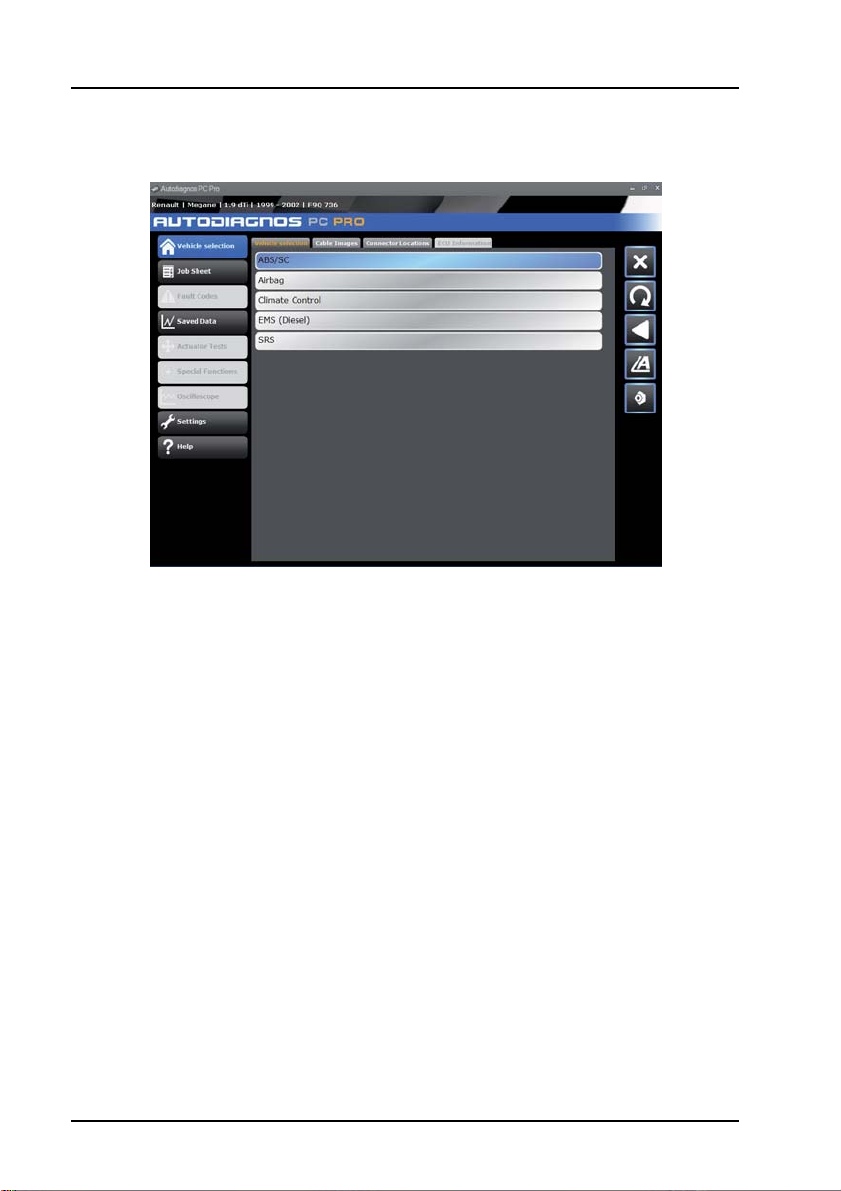
Selecting a vehicle system for testing
AU0072
Once a vehicle has been selected, the screen will show the systems available for
testing.
Selecting a system will automatically prompt the software to begin communication.
The communication LED on the Vehicle Interface will begin to flash, confirming that
the Autodiagnos PC Pro software is connecting to the system.
12
Page 18
Operating instructions
AU0080
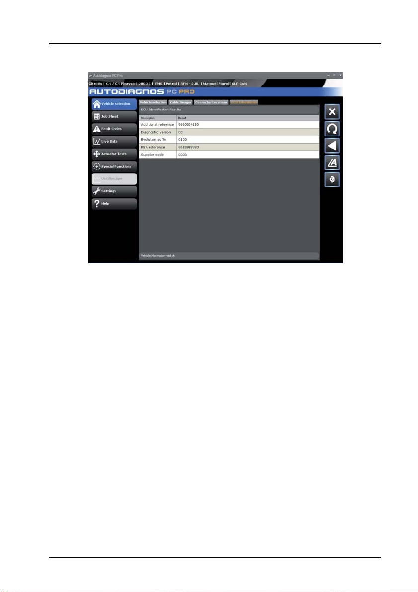
When the vehicle is ready for diagnostic tests, the diagnostic menu items on the left
hand side of the screen become enabled.
13
Page 19
Operating instructions
44
1
2
3
5
6
7 9 1010
8
AU0078
4
1
2
3
5
6
7910
8
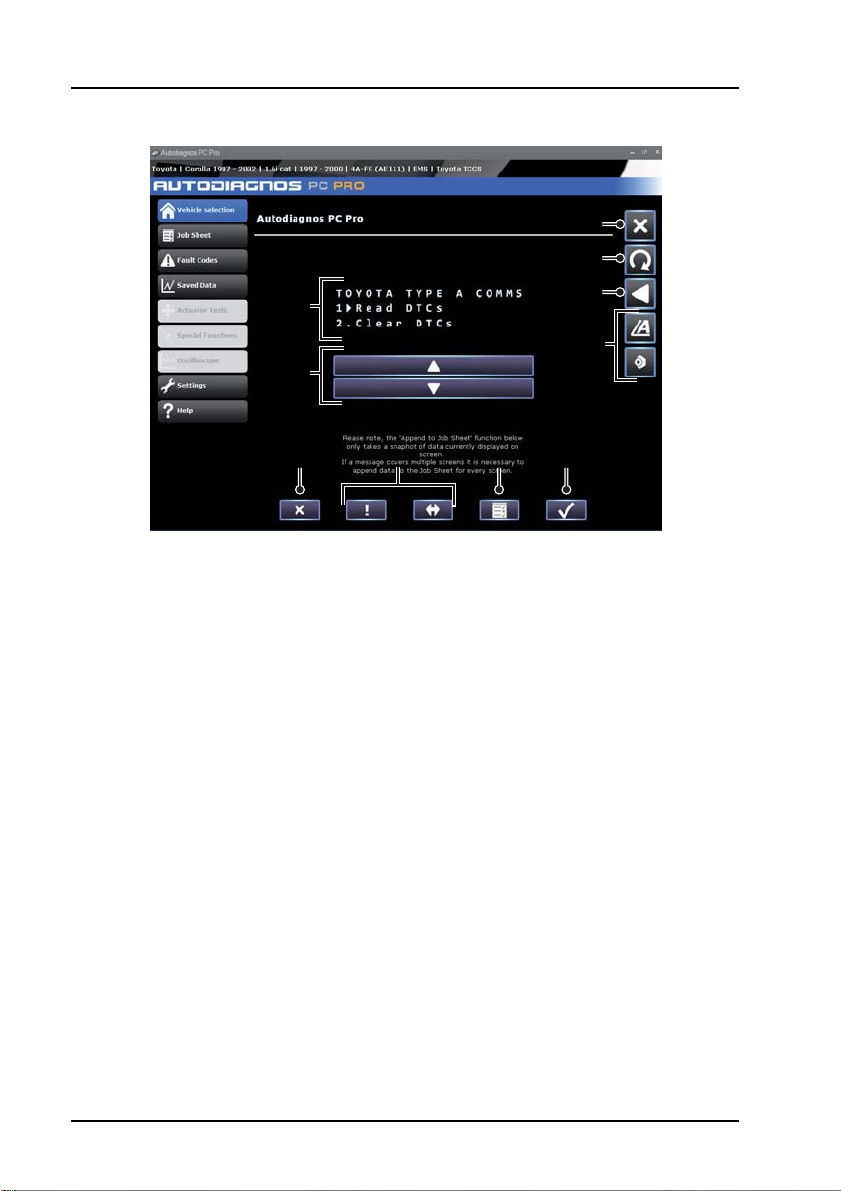
1. Exit the application
2. Restart vehicle selection
3. Return to previous screen
4. View technical data
5. Options / results display
6. Scroll up / down
7. Back
8. System dependent features
9. Jobsheet function
10. Confirm / next
Some vehicle systems will be displayed in a different format to the standard layout.
The options and results will be displayed within a system window which is controlled
by on-screen buttons.
The ‘scroll up / down’ buttons 6 are used to navigate through options and results. If
information spans multiple screens, it will be indicated by a series of dots.
14
Page 20
Operating instructions
11
22
33
44
AU0073
The ‘back’ button 7 returns to the previous screen.
The ‘confirm / next’ button 10 will confirm a selection or move to the next screen.
The ‘system dependent feature’ buttons 8 vary in their application and should only be
used when instructed to do so by Autodiagnos PC Pro.
Reading and clearing fault codes
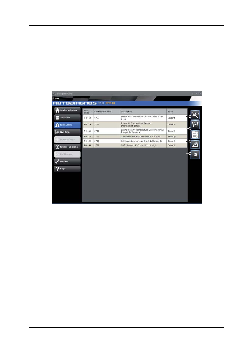
1. Refresh fault code list
2. Clear fault codes and freeze frame data
3. View Autodata technical data
4. View Vivid technical data
When the vehicle system has been identified, the ‘Fault Codes’ menu item will
become enabled where supported. This will allow fault codes to be read from the
selected system. It is also possible to clear fault codes from the system.
Press button 1 to refresh the list of fault codes.
Press button 2 to clear all fault codes and freeze frame data.
15
Page 21
Operating instructions
8
9
2
3
4
5
6
7
Reading live data
111
101010
2
8
9
AU0074
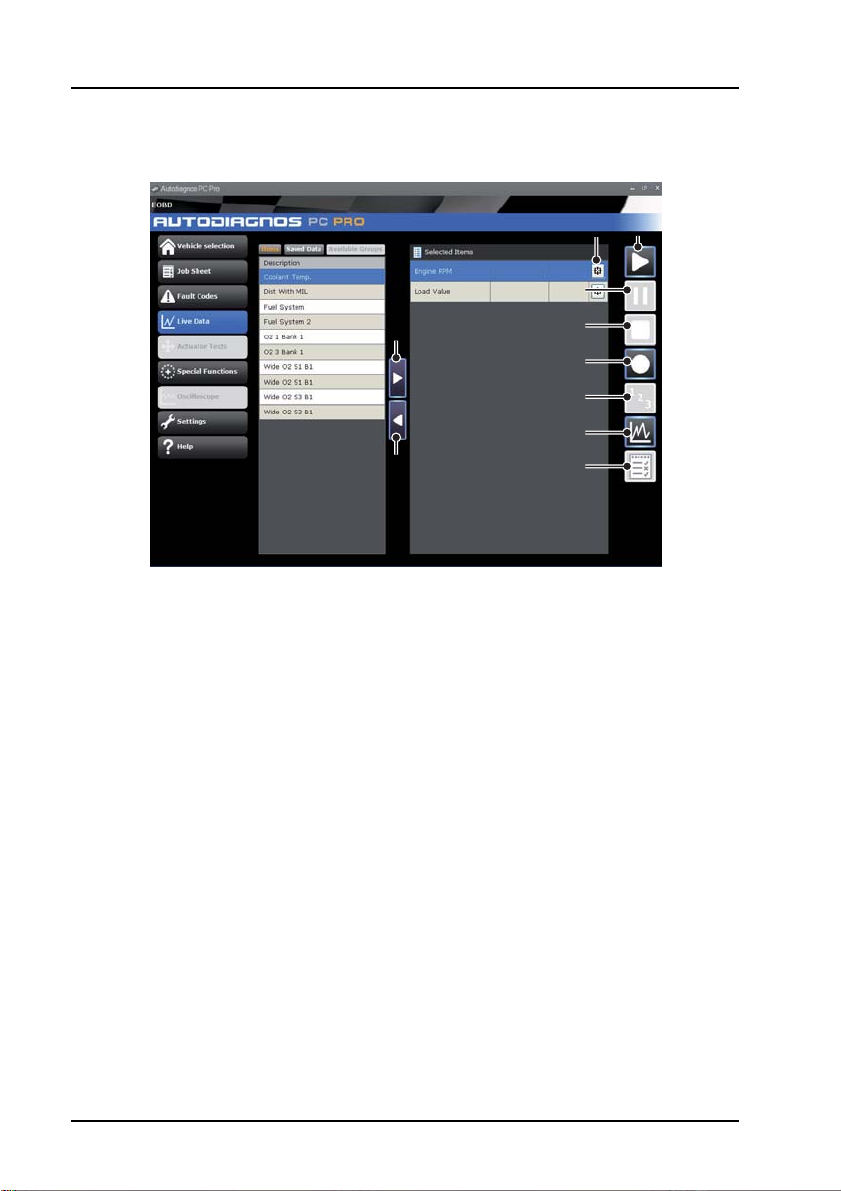
1. Start live data
2. Pause live data
3. Stop live data
4. Record live data
5. List mode
6. Graph mode
7. Add live data items to job sheet
8. Add live data items
9. Remove live data items
10. Alarms / triggers
The ‘Live Data’ menu item allows the display and recording of current live data that is
being output from the system.
To view the live data element, select the required item from the left side of the screen
and press the ‘Add live data items’ button. The number of live data elements that can
be viwed at a time depends on the system selected.
The live data can be displayed in a list form or as a graph by pressing button 5 or 6
respectively.
3
4
5
6
7
16
Page 22
Operating instructions
AU0079
To record live data, press button 4; this will request and immediately record the
selected live data items. To save the live data recording, press ‘Yes’ when prompted,
after recording has finished, and enter a description. Select the saved data tab to view
the saved data.
Alarms / triggers
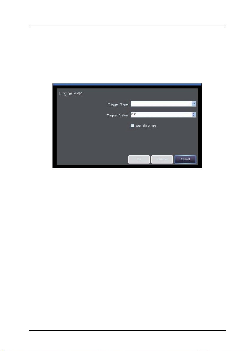
The ‘alarms and triggers’ screen allows the setting of an alarm to indicate when the
reported value of a live data item has fallen within a defined range.
When the value falls within the defined range, the background of the live data item will
change to red.
With the ‘Audible Alert’ option set, the PC will emit a ‘beep’ when the specified
parameters have been met. When the value falls outside the specified range, the
audible alert will cease but the background of the live data item will remain red.
To switch off an audible alarm, deselect the ‘Audible Alert’ option. Alternatively, press
the ‘Remove’ button to remove the alarm completely.
17
Page 23
Operating instructions
Graphs
AU0071
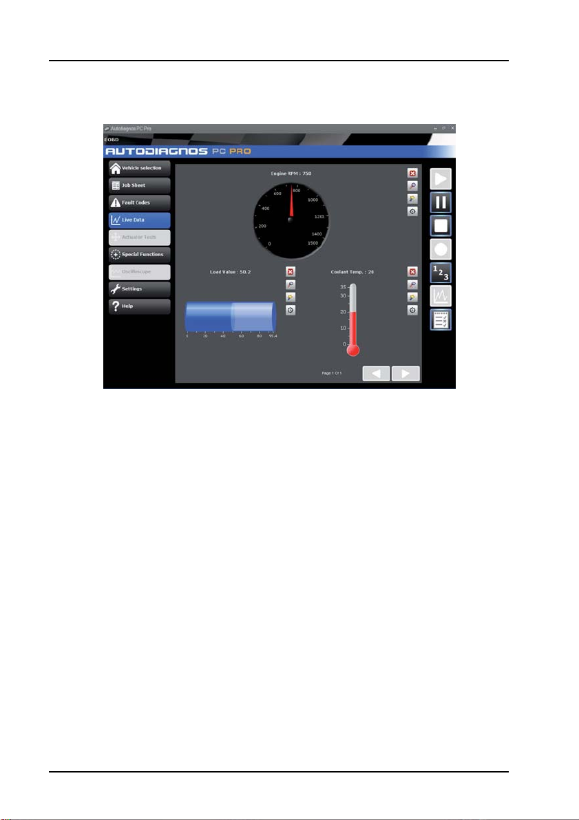
In the graph view, the graphs will automatically scale to fill the available space on the
screen. To enlarge the view of a particular graph select the ‘Zoom’ icon to the right of
the graph.
For further information, see ‘Live data icons’, page 19.
18
Page 24
Live data icons
CR0243
12345
678910
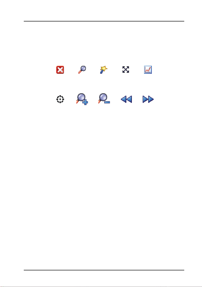
1. Remove
2. Zoom
3. Change display type
4. Enable cross hair
5. View entire graph
Operating instructions
6. Alarms/Triggers
7. Zoom in to axis
8. Zoom out from axis
9. Scroll left
10. Scroll right
19
Page 25

Operating instructions
Actuator tests
AU0070
The ‘Actuator Tests’ screen allows operation of compo nents within the selected
system to be forced.
Choose the component to be activated and select the ‘Activate’ button.
Observe operation of the component as the system provides no indication of whether
the activation has been successful.
20
Page 26
Technical data
11
22
AU0081
1. Autodata technical data
2. Vivid technical data
Operating instructions
The ‘Technical Data’ buttons will open the technical data application, for the specific
vehicle chosen, in a separate window.
Note: The type of technical data available is dependent on the installed technical data
package.
Dependent on the stage in the vehicle selection process at which the technical data
button was pressed, it may be necessary to select the specific vehicle. Select the
appropriate model from the list and then press ‘OK’ to proceed to the technical data
application.
21
Page 27
Operating instructions
Special functions
AU0076
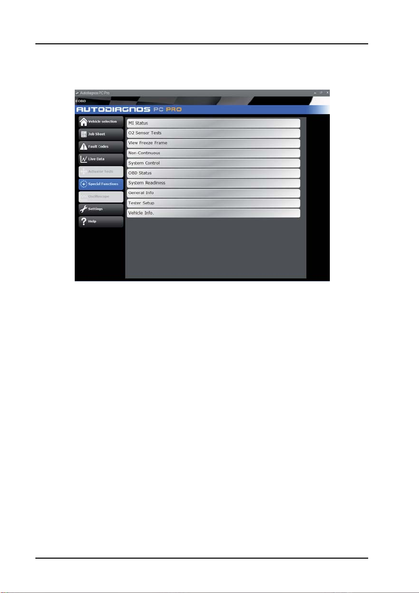
The ‘Special Functions’ screen allows various system tests to be undertaken. The
tests available will be determined by the system selected.
22
Page 28

Operating instructions
Troubleshooting
This table illustrates some of the most common causes of faults on the system.
Problem: Check:
System will not install from the CD• Ensure the person installing the Aut odi agno s
Wireless (Bluetooth)
communication not working
Communication problems
between Autodiagnos PC Pro
and vehicle.
Note: Typical message includes;
“Data Link Error”.
Note: If experiencing further technical difficulties with Autodiagnos PC Pro, please
contact Product Support. See ‘Product support hotline’, page 2.
PC Pro software has administrator rights on
the PC
• Navigate to the CD drive and launch the
“setup.exe”
• Ensure the operating system is Windows XP
Professional or Windows Vista
• Ensure the Bluetooth option is selected on
the ‘Settings’ screen
• Ensure the PC bluetooth settings have been
set correctly to allow communication with the
vehicle interface
• Ensure the vehicle interface is powered from
the vehicle’s diagnostic socket
• Ensure vehicle ignition is switched on
• Ensure correct cable is being used
• Ensure all connections are secure and cables
are in good condition
• Ensure vehicle system is supported by
Autodiagnos PC Pro.
23
Page 29
Operating instructions
CR0226
CR0225
CR0234
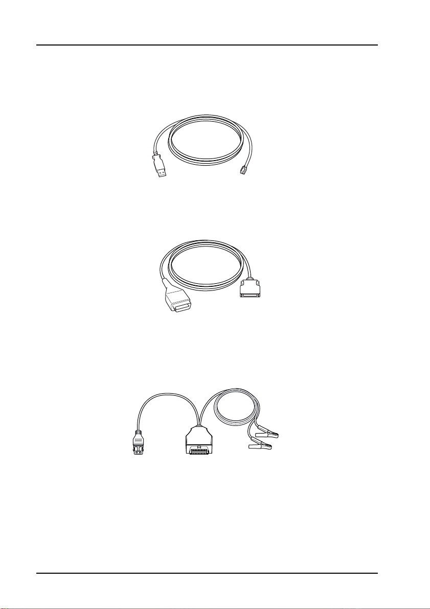
Cable identification
Standard cables
AS1215A USB cable
ASA32 EOBD cable
Optional cables
ASA33 PSA adapter cable (2-pin)
24
Page 30
Operating instructions
CR0231
CR0230
CR0229
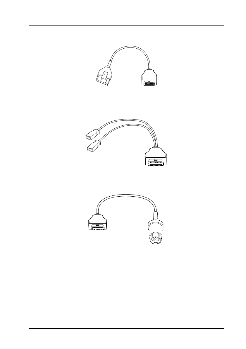
ASA34 PSA adapter cable (30-pin)
ASA35 VAG adapter cable
ASA36 Mercedes adapter cable
25
Page 31
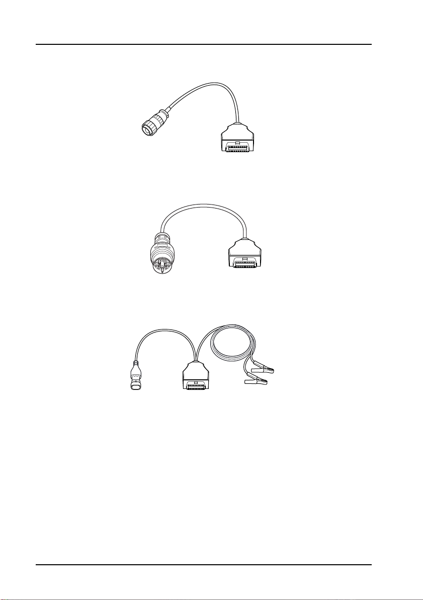
Operating instructions
CR0227
CR0235
ASA37 Mercedes Sprinter adapter cable
CR0228
ASA38 BMW adapter cable
ASA39 Fiat/Alfa/Lancia Adapter Cable
26
Page 32

Licence Agreement
Licence Agreement
Licence Agreement for Autodiagnos PC Pro
1. The Licence Agreement
Autodiagnos licences the software to you only upon the condition that you accept
all the terms contained in this Licence Agreement ("the Agreement"). Please
read the terms carefully before clicking the Yes button and finishing the
installation of the software and the data on your computer.
If you do not agree to these terms, then Autodiagnos is unwilling to licence the
software to you, in which event you should return the full product with proof of
purchase to the dealer from whom it was acquired within 30 da ys of purchase,
and your money will be refunded.
2. Subject of the Agreement
The subject of the Agreement is the Autodiagnos PC Pro software on disk
("AUTODIAGNOS PC PRO"). While Autodiagnos continues to own the software,
you will have certain rights to use the software and the data after your
acceptance of the conditions of this licence.
3. Rights of Use
You have the right to use the enclosed copy of Autodiagnos PC Pro for your
normal business on a single computer at one location. Use in a computer
network is only allowed if an appropriate Network Licence Agreement has been
concluded with Autodiagnos.
4. Copyright
a. Autodiagnos reserves all copyrights to AUTODIAGNOS PC PRO. This
applies in particular to all exploitation, publication and reproduction rights.
b. You may not copy, give away, hire out, lend, or make otherwise available,
Autodiagnos PC Pro to third parties without prior written consent of
Autodiagnos.
c. You may not transfer Autodiagnos PC Pro via a network or other data
transfer connection to another computer.
5. Compensation in the Event of Violation of the Agreement on Your Part
You shall be obliged to pay compensation if Autodiagnos incurs damages
through violation of the copyright on your part. In the event of violation of the
Agreement on your part, your right to use Autodiagnos PC Pro shall be
terminated without notice and compensation.
27
Page 33

Licence Agreement
6. Warranty and Liability
If any copy of Autodiagnos PC Pro is demonstrated to Autodiagnos to contain an
error or malfunction, Autodiagnos will use all reasonable endeavours to correct
such error or malfunction before the release of the next update, or (at its
discretion) replace such copy free of charge, provided that :
a. the application has been used at all times properly and in accordance with
the instructions for use;
b. no alteration, modification or addition has been made to the software without
Autodiagnos's prior written consent.
7. Waiver
Although every care has been taken to ensure that Autodiagnos PC Pro data is
accurate and complete, no liability other than that which may not be excluded by
law, can be accepted for any damages, loss or injury caused by errors or
omissions in the data. In no case shall Autodiagnos's liability exceed the Licence
Fee you paid for the use of Autodiagnos PC Pro during the current year. The
disclaimer and limitations set forth will apply regardless of whether you accept
AUTODIAGNOS PC PRO.
8. Assignment
Autodiagnos is at any time authorised to assign its rights and liabilities from this
software agreement to an affiliated company. By entering into the Agreement
you already agree with this assignment.
9. Law
The Agreement is governed by the laws of the U.K.
If you have any questions concerning this Agreement, please contact
Autodiagnos Product Support on +44 (0) 844 665 7623.
28
Page 34

Equipment disposal
Equipment disposal
Disposal of equipment
• Do not dispose of this equipment as miscellaneous solid
municipal waste but arrange to have it collected separately.
• The re-use or correct recycling of electronic equipment (EEE)
is important in order to protect the environment and the
wellbeing of humans.
• In accordance with European Directive WEEE 2002/96/EC,
special collection points are available for the delivery of waste
electrical and electronic equipment.
• The public administration and producers of electrical and electronic equipment are
involved in facilitating the processes of the re-use and recovery of waste electrical
and electronic equipment through the organisation of collection activities and the
use of appropriate planning arrangements.
• Unauthorised disposal of waste electrical and electronic equipment is punishable
by law with appropriate penalties.
Disposal of batteries
• Batteries must be recycled or disposed of properly. Do not throw
batteries away as part of normal refuse disposal.
• Do not throw batteries into open flame.
29
Page 35

Autodiagnos Limited
PC PRO
Unit 1 Hopton Estate • London Road • Devizes SN10 2EU
Tel: 0844 665 7623 • Fax: 0844 665 7603
www.autodiagnos.com
 Loading...