

Page 1

Autodesk NavisWorks Simulate 2009
User Manual
Autodesk, Inc.
Page 2

Autodesk NavisWorks Simulate 2009: User Manual
Autodesk, Inc.
Copyright © 2007 Autodesk, Inc.
Revision 6.1.46140
Autodesk, Inc.reserves the right to make changes in specification at any time and without notice. The information furnished by
Autodesk, Inc. in this publication is believed to be accurate; however, no responsibility is assumed for its use, nor for any
infringement of patents or other rights of third parties resulting from its use.
Autodesk, NavisWorks, AutoCAD, Revit, Inventor, and 3ds Max are registered trademarks or trademarks of Autodesk, Inc. All other
brand names, product names or trademarks belong to their respective holders. All rights reserved.
LightWorks, the LightWorks logo, LWA and LWA-Enabled are registered trademarks of LightWork Design Ltd. The LWA-Enabled
logo, Interactive Image Regeneration, IIR, A-Cubed, Feature-Following Anti-Aliasing and FFAA are all trademarks of LightWork
Design Ltd. All other trademarks, images and logos remain the property of their respective owners. Copyright of LightWork Design
Ltd. 1990-2006, 2007.
This software is based in part on the work of the Independent JPEG Group.
Contains a modified version of Open CASCADE libraries. See the license file "OpenCascadeLicense.txt" in the NavisWorks
installation directory. Source code is available from download.autodesk.com/us/navisworks/OpenCascade.zip.
Page 3

Page 4

Contents
Part 1. Welcome to Autodesk NavisWorks Simulate 2009 .............................................................. 1
Chapter 1. AutodeskNavisWorks Simulate2009 Readme ......................................................2
Chapter2.New Features .....................................................................................................5
Part2.Installation ........................................................................................................................7
Chapter 3. QuickStart toStand-Alone Installation .................................................................. 8
Chapter 4. Move toNavisWorks froma PreviousRelease ......................................................11
Chapter 5. Install NavisWorks for an Individual User ..............................................................12
Chapter 6. InstallNavisWorks forMultiple Users ....................................................................20
Chapter7.Installation Troubleshooting .................................................................................41
InstallingAutodesk NavisWorks Simulate2009 ..............................................................2
CustomerInvolvementProgram....................................................................................2
ProductNotes .............................................................................................................3
AutodeskFreedom ......................................................................................................3
Resources...................................................................................................................3
Known Problems inAutodesk NavisWorksSimulate 2009 .............................................. 4
Credits ........................................................................................................................4
Howto Prepare forInstallation ......................................................................................8
Howto Review SystemRequirements ...................................................................8
Howto UnderstandAdministrative Permission Requirements .................................8
How to InstallMultiple orBundled Products ........................................................... 8
How to Locate YourAutodesk NavisWorks Simulate 2009 SerialNumber ............... 8
How to AvoidData LossDuring Installation ........................................................... 9
How to Install andRun AutodeskNavisWorks Simulate2009 ......................................... 9
How to InstallAutodesk NavisWorksSimulate 2009 ............................................... 9
Howto Registerand Activate NavisWorks ............................................................. 9
HowtoLaunch NavisWorks ..................................................................................10
How to LaunchNavisWorks inAnother Language ..................................................10
TheNavisWorksInstallation Wizard ..............................................................................12
SystemRequirements ..................................................................................................12
InstallNavisWorks .......................................................................................................13
RegisterandActivate NavisWorks ................................................................................16
AddorRemove Features .............................................................................................17
Reinstall or RepairAutodesk NavisWorksSimulate 2009 ...............................................17
UninstallAutodesk NavisWorks Simulate2009 ..............................................................18
QuickStart to NetworkInstallation ................................................................................20
Howto Prepare forDeployment ............................................................................20
How to SetUp aLicense Server ...........................................................................21
How to Set Up and Distribute the Program ............................................................ 25
SystemRequirements for aDeployment .......................................................................28
CreatingNetworkDeployments ....................................................................................30
PreliminaryTasks fora Network Deployment ......................................................... 30
Use the Installation Wizardto SetUp aDeployment ...............................................32
PointUsers tothe Administrative Image ................................................................39
UninstalltheProgram...........................................................................................40
Whatare theminimum system requirements? ...............................................................41
How can I check my graphicscard driver to see if it needsto be updated? ...................... 41
What isthe difference between a stand-alone license and a network license? ................. 42
What isthe benefit tousing a networklicensed version ofthe software? .......................... 42
When performing a Typical installation, what gets installed? ........................................... 42
Whereare my productmanuals? ..................................................................................43
DeploymentIssues ......................................................................................................43
iv
Page 5

Autodesk NavisWorks Simulate 2009
Is therea checklist I can refer to when performing a deployment? ........................... 43
Whereshould deployments belocated? ................................................................43
Where canI check if service packs are available for my software? .......................... 43
NetworkingIssues .......................................................................................................44
Where do Ifind myserver name? .........................................................................44
If I choose to create a log file, what kindof information does the log file contain? ..... 44
MaintenanceIssues .....................................................................................................44
Is itpossible to changethe installation folderwhen adding orremoving features? .... 44
When should I reinstallthe product instead of arepair? .......................................... 44
Do I need myoriginal disk to reinstall mysoftware? ...............................................44
When Iuninstall my software, what files are left on my system? .............................. 44
Part3. Basic NavisWorksFunctionality .........................................................................................46
Chapter8.Overview ............................................................................................................47
Chapter9.File Management ................................................................................................48
FileMenu ....................................................................................................................48
NewFiles ....................................................................................................................48
RefreshingFiles ..........................................................................................................49
OpeningFiles ..............................................................................................................49
OpeningFilesvia URL .................................................................................................50
AppendingFiles ...........................................................................................................50
MergingFiles ...............................................................................................................51
SavingFiles ................................................................................................................51
SavingandRenaming Files ..........................................................................................52
PublishingFiles ...........................................................................................................52
Printing .......................................................................................................................52
PrintingtheCurrent Viewpoint ..............................................................................52
PreviewingPrintouts ............................................................................................53
Settingupprintouts ..............................................................................................53
DeletingFiles ..............................................................................................................54
EmailingFiles ..............................................................................................................54
ImportingFiles .............................................................................................................55
ImportingPDSTags.............................................................................................55
ImportingPDSDisplay Sets .................................................................................56
ImportingViewpointsXML ....................................................................................57
ImportingSearchXML .........................................................................................58
ImportingSearchSets XML ..................................................................................59
ExportingFiles.............................................................................................................60
Exportingto aPiranesi EPix Format ......................................................................61
ExportinganImage ..............................................................................................61
ExportinganAnimation ........................................................................................63
Controllingthe Sizeof an Image ...........................................................................65
ExportingPDSTags ............................................................................................66
ExportingViewpoints ...........................................................................................66
ExportingCurrentSearch .....................................................................................67
ExportingSearchSets .........................................................................................67
ExportingViewpointsReport.................................................................................67
ExportingtoAutodesk DWF .................................................................................68
Exportingto Google EarthKML ............................................................................68
QuittingNavisWorks ....................................................................................................71
Chapter10.Converting Files ................................................................................................72
FileReaders ................................................................................................................72
NWFFiles ...........................................................................................................73
NWDFiles ...........................................................................................................73
NWCFiles ...........................................................................................................74
DWGandDXF Files ............................................................................................76
DWFFiles ...........................................................................................................80
BentleyAutoPLANTFiles .....................................................................................82
v
Page 6

Autodesk NavisWorks Simulate 2009
3DSFiles ............................................................................................................84
DGNandPRP Files .............................................................................................85
MANFiles ...........................................................................................................88
PDSFiles ............................................................................................................90
IGESFiles ...........................................................................................................91
STEPFiles ..........................................................................................................93
InventorFiles .......................................................................................................95
VRMLworldfiles..................................................................................................96
RieglScanFiles ..................................................................................................98
FaroScanFiles ...................................................................................................100
LeicaScanFiles ..................................................................................................101
Z+FScanFiles ....................................................................................................102
ASCIILaserScan Files ........................................................................................104
STLStereolithographyfiles...................................................................................105
AVEVAReview RVMand RVS files ...................................................................... 106
IFCfiles ..............................................................................................................109
SketchupSKPfiles ..............................................................................................111
FileExporters ..............................................................................................................113
AutoCAD.nwcExporter .......................................................................................114
Revit.nwcExporter ..............................................................................................116
MicroStation.nwcExporter ...................................................................................119
Vizand Max .nwcExporter ...................................................................................121
ArchiCAD.nwcExporter.......................................................................................125
CADPreviewing ..........................................................................................................127
NavisWorksNavigatorfor AutoCAD ......................................................................127
Chapter11.Publishing .........................................................................................................129
PublishingfromNavisWorks .........................................................................................129
PublishingfromAutoCAD .............................................................................................131
PublishingfromMicroStation ........................................................................................132
Freedom .....................................................................................................................134
Chapter12.Navigating ........................................................................................................139
NavigationModes ........................................................................................................139
Walking...............................................................................................................140
LookingAround ...................................................................................................140
Zooming..............................................................................................................141
Zoomingtoa Box ................................................................................................141
Panning ..............................................................................................................142
Orbiting ...............................................................................................................142
Examining ...........................................................................................................142
Flying..................................................................................................................143
Spinningona Turntable .......................................................................................143
NavigationTools ..........................................................................................................144
ViewingEverything ..............................................................................................145
ViewingSelectedItems ........................................................................................145
Focusing .............................................................................................................146
PerspectiveCamera ............................................................................................146
OrthographicCamera...........................................................................................146
CollisionDetection ...............................................................................................147
Gravity ................................................................................................................148
Crouching ...........................................................................................................149
ThirdPersonView ...............................................................................................149
PresetViewpoints ................................................................................................150
Straighten ...........................................................................................................151
SetWorldUp .......................................................................................................151
CameraTilt .................................................................................................................152
ThumbnailViews .........................................................................................................153
UsingaSpaceBall .......................................................................................................155
vi
Page 7

Autodesk NavisWorks Simulate 2009
Chapter13.Selecting Items .................................................................................................157
SelectionTrees ...........................................................................................................157
InteractiveSelection .....................................................................................................159
SelectMode ........................................................................................................160
SelectBoxMode .................................................................................................160
SelectionCommands ...........................................................................................161
SelectionandSearch Sets ...........................................................................................162
SavingSelection and SearchSets ........................................................................162
RecallingSelection and SearchSets .....................................................................163
ManagingSelectionSets ......................................................................................163
SelectionResolution ....................................................................................................165
SelectionOptions ........................................................................................................166
Chapter14.Finding .............................................................................................................168
Properties ...................................................................................................................168
FindingItems ...............................................................................................................169
QuickFind ...................................................................................................................171
FindingComments .......................................................................................................172
Chapter15.Editing ..............................................................................................................175
Holdingandreleasing objects .......................................................................................175
Undo/Redo..................................................................................................................176
HidingItems ................................................................................................................178
Makingitemsrequired ..................................................................................................178
HidingUnselectedItems ..............................................................................................178
OverridingItemProperties ............................................................................................179
OverridingColor ..................................................................................................179
OverridingTransparency ......................................................................................179
OverridingTransforms .........................................................................................180
OverridingHyperlinks ...........................................................................................181
ResettingOverridenProperties .....................................................................................181
ResettingColorsand Transparencies ....................................................................181
ResettingHyperlinks ............................................................................................181
ResettingItems'Positions ....................................................................................181
ResettingAllOverriden Properties ................................................................................182
ResettingAll Colors andTransparencies ...............................................................182
ResettingAllItems' Hyperlinks ..............................................................................182
RevealingAllItems ..............................................................................................182
MakingAllItems Unrequired .................................................................................182
ResettingAllItems' Positions ................................................................................183
CustomProperties .......................................................................................................183
AddUserData Tab ..............................................................................................183
RenameUserData Tab .......................................................................................183
AddNewProperty................................................................................................184
EditPropertyValue ..............................................................................................184
RenameProperty ................................................................................................185
DeleteProperty ...................................................................................................185
DeleteUserData Tab ..........................................................................................185
Settinga File'sUnits and Transform .............................................................................. 186
Chapter16.Display Modes ..................................................................................................188
RenderingStyles .........................................................................................................188
Lighting ...............................................................................................................188
RenderModes .....................................................................................................193
DisplayPrimitives ................................................................................................194
BackgroundColor ................................................................................................196
CullingOptions ............................................................................................................196
OrientationOptions ......................................................................................................198
SpeedOptions.............................................................................................................199
DisplayOptions ...........................................................................................................201
vii
Page 8

Autodesk NavisWorks Simulate 2009
PerformanceOptions ...................................................................................................202
PresenterOptions ........................................................................................................204
Chapter17.Viewpoints ........................................................................................................207
SavingViewpoints .......................................................................................................207
RecallingViewpoints ....................................................................................................207
TheViewpointsControl Bar ..........................................................................................208
TheViewpointShortcut Menus .....................................................................................209
TheViewpoints ControlBar Shorcut Menu ............................................................209
Viewpoints ..........................................................................................................210
ViewpointAnimations ...........................................................................................210
Folders ...............................................................................................................211
EditingViewpoints .......................................................................................................211
ViewpointsOptions ......................................................................................................214
Chapter18.Sectioning .........................................................................................................218
Sectioningamodel ......................................................................................................218
LinkingSections ..........................................................................................................220
Chapter19.Animation .........................................................................................................222
TheAnimationToolbar .................................................................................................222
TheViewpointsControl Bar ..........................................................................................223
CreatingViewpointAnimations .....................................................................................224
EditingViewpointAnimations........................................................................................225
AnimationCuts ............................................................................................................226
PlayingBackAnimations ..............................................................................................226
Chapter20.Reviewing .........................................................................................................228
Commenting................................................................................................................228
AddingComments ...............................................................................................229
EditingComments ...............................................................................................231
DeletingComments .............................................................................................232
Redlining.....................................................................................................................233
AddingRedlines ..................................................................................................233
AddingRedlineTags............................................................................................235
FindingRedlineTags ...........................................................................................236
EditingRedlineTags ............................................................................................237
Measuring ...................................................................................................................237
MeasuringTools ..................................................................................................238
Snapping ............................................................................................................240
TransformingObjects ...........................................................................................241
MeasureOptions .................................................................................................243
Hyperlinks ...................................................................................................................244
AddingHyperlinks ................................................................................................245
DisplayingHyperlinks ...........................................................................................246
FollowingHyperlinks ............................................................................................247
EditingHyperlinks ................................................................................................247
DeletingHyperlinks ..............................................................................................249
HyperlinksOptions ...............................................................................................250
SmartTags .................................................................................................................254
SmartTagsOptions .............................................................................................254
Collaboration ...............................................................................................................257
SwitchBack .................................................................................................................260
Chapter21.Object Manipulation ...........................................................................................262
UsingSnapping ...........................................................................................................262
HighlightingObjects .....................................................................................................263
MovingObjects ............................................................................................................265
RotatingObjects ..........................................................................................................266
ScalingObjects ...........................................................................................................267
ChangingColor ...........................................................................................................268
ChangingTransparency ...............................................................................................268
viii
Page 9

Autodesk NavisWorks Simulate 2009
Usingthe Manual EntryBoxes ......................................................................................268
Chapter22.Interface ...........................................................................................................270
TheMainInterface Components ...................................................................................270
TheMenuBar .....................................................................................................270
TheToolbars .......................................................................................................271
TheMainNavigation Window ...............................................................................272
TheControlBars .................................................................................................272
TheStatusBar ....................................................................................................273
ViewMenu ..................................................................................................................274
ControlBars ........................................................................................................275
Workspaces ........................................................................................................275
CustomizingToolbars ..........................................................................................277
WorkspaceToolbar ..............................................................................................284
CustomizingtheMain Window ..............................................................................285
StereoRendering ................................................................................................288
SceneStatistics ...................................................................................................289
Units ...........................................................................................................................290
Profiles .......................................................................................................................291
SearchDirectories .......................................................................................................292
Chapter23.Tools ................................................................................................................293
ComparingModels .......................................................................................................293
Chapter24.Options .............................................................................................................296
FileOptions .................................................................................................................296
LocationOptions ..........................................................................................................296
EnvironmentOptions ...................................................................................................297
GlobalOptions.............................................................................................................298
ConfiguringGlobalOptions...................................................................................299
Importingand Exporting GlobalOptions ................................................................301
Chapter25.DataTools .........................................................................................................305
AddingDatabaseLinks ................................................................................................305
ConfiguringDatabaseLinks..........................................................................................307
ManagingDatabaseLinks ............................................................................................310
FullTagList ................................................................................................................314
Chapter26.Getting Help ......................................................................................................317
HelpTopics .................................................................................................................317
What'sThis? ...............................................................................................................318
NavisWorksonthe Web ...............................................................................................318
License .......................................................................................................................319
CustomerInvolvementProgram....................................................................................321
SystemInfo .................................................................................................................322
AboutNavisWorks .......................................................................................................322
Part4.Using Presenter ................................................................................................................324
Chapter27. Overview ofPresenter .......................................................................................325
Workingwith the PresenterWindow ..............................................................................325
TheRenderingStyle Toolbar ........................................................................................326
UsingthePresenter Archives .......................................................................................326
TheUserArchive .................................................................................................327
AdditionalArchives ..............................................................................................327
Chapter28.Rendering Scenes .............................................................................................329
SettingUp AndRendering A Scene ..............................................................................329
ExportingRenderedOutput ..........................................................................................329
Chapter29.Presenter Materials ...........................................................................................333
MaterialsTab ..............................................................................................................333
ApplyingPresenterMaterials ........................................................................................333
RemovingPresenterMaterials ......................................................................................334
OrganizingandManaging Materials ..............................................................................335
EditingPresenterMaterials...........................................................................................337
ix
Page 10

Autodesk NavisWorks Simulate 2009
AdvancedMaterials .....................................................................................................341
Chapter30.Presenter Lighting .............................................................................................344
LightingTab ................................................................................................................344
AddingandPositioning Lights .......................................................................................344
OrganizingandManaging Lights ...................................................................................346
EditingLights ...............................................................................................................348
ShadowCasting ..........................................................................................................351
AdvancedLighting .......................................................................................................352
SoftShadows ......................................................................................................352
PhysicallyAccurateLights ....................................................................................352
VolumetricLights .................................................................................................353
Image-basedLighting...........................................................................................353
Chapter31.Presenter RPCs ................................................................................................356
RPCTab .....................................................................................................................356
Chapter32.Rendering Effects ..............................................................................................360
EffectsTab ..................................................................................................................360
BackgroundEffects ......................................................................................................360
ForegroundEffects ......................................................................................................363
Chapter33.Rendering Styles ...............................................................................................365
RenderingTab.............................................................................................................365
RenderingStyles .........................................................................................................365
PredefinedRenderingStyles ........................................................................................366
AutoExposure .............................................................................................................367
Chapter34.Texture Space ...................................................................................................369
Chapter35.Presenter Rules ................................................................................................372
RulesTab ...................................................................................................................372
PredefinedRules .........................................................................................................372
CustomRules ..............................................................................................................373
ApplyingPresenterRules .............................................................................................375
ThePresenterRules Example ......................................................................................375
Part5.Object Animation ..............................................................................................................379
Chapter36.Overview ..........................................................................................................380
Basicterminology ........................................................................................................380
Scope .........................................................................................................................380
Chapter 37. Workingwith ObjectAnimation Windows ............................................................ 382
TheAnimatorWindow ..................................................................................................382
TheAnimatorToolbar ..........................................................................................382
TheSceneView ..................................................................................................384
TheTimelineView ...............................................................................................386
TheManualEntry Bar ..........................................................................................388
TheScripterWindow....................................................................................................389
TheScriptView ...................................................................................................390
TheEventView ...................................................................................................392
TheActionView ..................................................................................................393
ThePropertiesView.............................................................................................395
Chapter38.Creating Animations ..........................................................................................397
AnimationScenes ........................................................................................................397
AddingScenes ....................................................................................................397
DeletingScenes ..................................................................................................397
OrganizingScenes ..............................................................................................398
AnimationSets ............................................................................................................399
AddingAnimationSets .........................................................................................399
UpdatingAnimationSets ......................................................................................400
ManipulatingGeometryObjects ............................................................................401
Cameras .....................................................................................................................410
AddingCameras ..................................................................................................410
ManipulatingCameraViewpoints ..........................................................................411
x
Page 11

Autodesk NavisWorks Simulate 2009
SectionPlaneSet ........................................................................................................411
AddingSectionPlane Sets ...................................................................................411
ManipulatingSectionalCuts .................................................................................411
Keyframes...................................................................................................................412
CapturingKeyframes ...........................................................................................412
EditingKeyframes................................................................................................413
PlayingAnimationScenes ............................................................................................417
Chapter39.Adding Interactivity ............................................................................................418
AnimationScripts .........................................................................................................418
AddingScripts .....................................................................................................418
DeletingScripts ...................................................................................................418
OrganizingScripts ...............................................................................................419
Events ........................................................................................................................419
AddingEvents .....................................................................................................420
TestingEvents.....................................................................................................420
ConfiguringEvents ..............................................................................................420
Actions........................................................................................................................424
AddingActions ....................................................................................................424
TestingActions ....................................................................................................424
ConfiguringActions ..............................................................................................424
EnablingScripting ........................................................................................................429
Chapter40.Animation Exercise ............................................................................................430
OpeningaGatehouse Door ..........................................................................................430
AnimatingaDoor .................................................................................................430
CreatingScripts ...................................................................................................433
TestingtheResults ..............................................................................................435
Part6.Using TimeLiner ................................................................................................................436
Chapter41. Overview ofTimeLiner .......................................................................................437
Workingwith the TimeLinerWindow .............................................................................437
TheTasksTab ....................................................................................................438
TheLinksTab .....................................................................................................442
TheConfigureTab ...............................................................................................444
TheRulesTab .....................................................................................................446
TheSimulateTab ................................................................................................446
TheSelectLink Dialog .........................................................................................448
FieldSelectorDialog ............................................................................................448
TheSimulationSettings Dialog .............................................................................450
TheOverlayText Dialog .......................................................................................456
GettingStarted ............................................................................................................458
Chapter42.TimeLiner Tasks ................................................................................................463
AdjustingtheTask View ...............................................................................................463
UserColumns .............................................................................................................464
CreatingTasks ............................................................................................................464
AddingTasksManually ........................................................................................465
AddingTasksAutomatically..................................................................................465
EditingTasks ...............................................................................................................466
DeletingTasks.............................................................................................................468
AttachingTasksto Geometry ........................................................................................468
AttachingTasksManually.....................................................................................469
UsingRules to AttachTasks .................................................................................470
ValidatingProjectSchedule ..........................................................................................472
Chapter 43. Linkingto ExternalProject Files..........................................................................474
SupportedSchedulingSoftware ....................................................................................474
MicrosoftProject2000 .........................................................................................475
MicrosoftProject ..................................................................................................475
MicrosoftProjectMPX..........................................................................................475
PrimaveraProjectPlanner ....................................................................................475
xi
Page 12

Autodesk NavisWorks Simulate 2009
PrimaveraProject Management4 and 5 ................................................................ 475
AstaPowerProject ..............................................................................................476
AddingandManaging Links .........................................................................................476
AddingLinks .......................................................................................................476
EditingLinks ........................................................................................................477
DeletingLinks ......................................................................................................477
BuildingTasksfrom Links .............................................................................................478
SynchronizingTasks with ProjectChanges ...................................................................478
Chapter44.4D Simulation ...................................................................................................480
PlayingSimulations .....................................................................................................480
ConfiguringSimulations ...............................................................................................480
SimulationPlayback .............................................................................................480
SimulationAppearance ........................................................................................481
Chapter45.Export...............................................................................................................483
Chapter46.TimeLiner Options .............................................................................................484
Chapter47.Adding Animation ..............................................................................................485
Overview.....................................................................................................................485
AddingAnimation toan Entire Schedule ........................................................................485
AddingAnimationto Tasks ...........................................................................................489
AddingScriptsto Tasks ................................................................................................490
Glossary .....................................................................................................................................491
Index ..........................................................................................................................................496
xii
Page 13

Part 1. Welcome to Autodesk
NavisWorks Simulate 2009
Autodesk NavisWorks Simulate 2009 software provides 4D analysis and visualization that enables design
professionals to share and combine output for clear, descriptive content that helps demonstrate design
intent and validate decisions. Entire projects can be replicated with dynamic, photorealistic views and 4D
construction schedules to demonstrate and clarify all options.
In this documentation set you can find information on:
• Installation
• Basic NavisWorks Functionality
• Presenter
• Object Animation
• TimeLiner
Page 14

Chapter 1. Autodesk NavisWorks Simulate 2009 Readme
This section contains late-breaking information about Autodesk NavisWorks Simulate 2009. For new and
updated information about all Autodesk© products, visit our website at http://www.autodesk.com.
Installing Autodesk NavisWorks Simulate 2009
Release Version with Beta
If you have previously installed any beta version (including RC versions) of Autodesk NavisWorks
Simulate 2009, you must completely uninstall these pre-release versions before installing the retail
version. Instructions to do this are posted on the beta portal in the Beta Readme files.
Exporters for 64 bit CAD systems
Autodesk NavisWorks Simulate 2009 includes exporters for 64 bit versions of 3D Studio Max (9, 2008,
2009) and AutoCAD based products (2008, 2009). These exporters are packaged as a separate product
within the installer called "Autodesk NavisWorks 2009 (64 bit exporters)". This product will only be
available for installation on a 64 bit operating system and will be installed by default.
The 64 bit exporters require Autodesk NavisWorks Simulate 2009 to be installed for full functionality.
Autodesk NavisWorks Simulate 2009 should not be uninstalled without also uninstalling "Autodesk
NavisWorks 2009 (64 bit exporters)".
Customer Involvement Program
During the first week of Autodesk NavisWorks Simulate 2009 use, a new window will appear to invite you
to join the Customer Involvement Program (CIP). By joining, NavisWorks will send anonymous data to
Autodesk related to the use of the application.
We strongly encourage you to participate in the program, and assure you there is no risk to your privacy.
We hope you will help us improve our product through this effort.
What does CIP track?
• Number of minutes you are running the software.
• Number of sessions that end due to stability issues.
• Menu actions triggered.
• Import/export actions (including file extension used).
• Scene statistics after a load or import (number of objects, faces, vertices etc.).
• Machine configuration (resolution, hard disks).
• Other Autodesk products installed.
• Plug-in (DLLS) installed with NavisWorks.
2
Page 15

What does CIP not track?
• There is no way for CIP to track any information related to the user.
• There is also no way to track information outside of Autodesk products.
To turn CIP on and off:
• Turn CIP on or off by going to Help > Customer Involvement Program.
The dialog will appear, allowing you to switch it on or off.
Product Notes
Supported file formats and applications
Autodesk NavisWorks Simulate 2009
Readme
• For an up to date list of supported file formats and applications go to NavisWorks Product Center.
Autodesk Freedom
• A free 3D viewer for NavisWorks NWD and Autodesk DWF files, Freedom is the answer for those
without design software or specialist skills that want to explore a project model.
• Freedom offers an unrestricted, easy to use interface for real-time navigation of even the largest 3D
models complete with textures and materials, as well as animation playback, hyperlinks and saved
viewpoints.
• Click here to install Freedom.
Resources
• NavisWorks is provided with a number of sample models, which are installed in the Examples
directory within the Autodesk NavisWorks Simulate 2009 installation directory
• NavisWorks has a powerful API (Application Programming Interface) that allows developers to
customize the product. The API documentation and example files are installed in the API directory
within the Autodesk NavisWorks Simulate 2009 installation directory
• NavisWorks has support for ArchVision's RPCs for use with Presenter, and is provided with a number
of sample RPC files. The sample RPCs are installed in the
Presenter\lads\layla_data\textures\RPC directory within the Autodesk NavisWorks
Simulate 2009 installation directory.
• NavisWorks has support for Image Based Lighting through the use of High Dynamic Range Images
(HDRIs). The LightWorks User site has a number of resources for users of HDR Images:
3
Page 16

Autodesk NavisWorks Simulate 2009
Readme
Access the LightWork Design HDRI Resource Page
Access the LightWork Design HDRI Starter Collection
• Microsoft .NET Framework
Earlier versions of Revit (Building 8 / Structures 2) require the .NET Framework version 1.1 to be
separately installed. If the .Net Framework version 1.1 is not installed an error message will be
displayed when Revit is started. You can download a copy of the .Net Framework version 1.1 by
searching for ".Net Framework version 1.1 redistributable package" in the downloads section of
Microsoft's website.
• Adobe Reader
This is free software that enables the viewing and printing of Adobe's Portable Document Format
(PDF) files.
NavisWorks documentation is stored in PDF format, therefore, requiring this viewer to read them.
Download Adobe Reader
Known Problems in Autodesk NavisWorks Simulate 2009
For an up-to-date list of outstanding issues in Autodesk NavisWorks Simulate 2009, visit the NavisWorks
website at www.autodesk.com/navisworks.
Credits
Autodesk kindly acknowledges the following contributors to the NavisWorks example models:
• National Ice Centre model courtesy of Design and Property services, Nottingham City Council,
Nottingham, England.
• Scorpion TKX890 Snowmobile model courtesy of Scorpion Recreational Products, L.L.C. Manistee,
Michigan, USA
• City of Bath model courtesy of the Centre for Advanced Studies in Architecture, University of Bath,
England.
• Gatehouse model courtesy of Dr. David Kerr, Taylor Woodrow, Taywood House, 345 Ruislip Road,
Southall UB1 2QX, England.
• Eircom Park model courtesy of HBG Construction Ltd., Merit House, Colindale, London NW9 5AF,
England. Architects: RHWL Partnership, 77 Endell St. London WC2H 9DZ, England. Client: IMG
Ireland, 5 Clare St. Dublin 2 Ireland.
• KLM model courtesy of Laing Ltd, Maxted House, 13 Maxted Road, Hemel Hempstead HP2 7DX,
England.
4
Page 17

Chapter 2. New Features
Autodesk NavisWorks Simulate 2009 contains many new features and enhancements.
Interface Enhancements
• Object Animation
Animate objects across an animation timeline using simple but powerful object manipulation and
animation tools.
Interact with objects whilst they interact with the viewer, all via new simple but powerful scripting tools.
Link object movement with TimeLiner for precise object movement scheduling based on project tasks,
for more informative and realistic 4D process planning.
Link object movement with Presenter for enhanced worksite realism in exported photo-realistic
animations.
• .NET GUI Modernization
Up-to-date look and feel including new icons, improved control bar docking and tabbed control bars.
• Workspaces
Allow predefined default window and menu layouts, as well as full customization and sharing of
layouts across multiple PCs.
• New editor for Global Options.
A change from complex tabs to a logical tree structure, making finding options much simpler. Also
making global options sharable across multiple PCs through import and export.
Licensing Enhancements
• FlexLM Licensing
The capability of check-in / check-out of licenses, timed-out licenses to automatically return
checked-out licenses after a set period of time.
• Autodesk Standalone Licensing
Support for the well-known and well-documented Autodesk standard licensing technology.
Operating System Support
• Microsoft Vista Support
Full support for Microsof's latest operating system.
• 64-bit Support
5
Page 18

New Features
Support for 64-bit versions of both XP and Vista.
File Formats
• 3D Text Support
Visualization of 3D text from AutoCAD and MicroStation.
• Parametric Support
Increasing cylinder accuracy, and dramatically reducing the memory footprint of file formats containing
them. Of key benefit to the MicroStation exporter and DGN file reader.
• Object Animation Playback
Playback of object animations inside NWD and NWC files that have been created in Autodesk
NavisWorks Manage 2009 or Autodesk NavisWorks Simulate 2009.
• File Format Updates
AutoCAD 2009 (32-bit and 64-bit)
Revit 2009
MAX 2008 and 2009
MAX 9 (32-bit and 64-bit)
VIZ 2008 and 2009
Inventor 2009
ArchiCAD 11
Faro 4.1
MicroGDS 10
Primavera v6
6
Page 19

Part 2. Installation
This section provides step-by-step installation instructions for Autodesk NavisWorks Simulate 2009. In
particular, you will learn how to:
• Install stand-alone versions of the program
• Install network-licensed or multi-seat stand-alone versions of the program
• Upgrade the program
• Troubleshoot your installation
Page 20

Chapter 3. Quick Start to Stand-Alone Installation
This section provides step-by-step instructions about how to install Autodesk NavisWorks Simulate 2009
on your system. You should read the entire Standalone Installation Guide if you have any questions that
are not addressed in this Quick Start section.
For information about installing network-licensed or multi-seat stand-alone versions of the program, see
the Network Installation Guide.
How to Prepare for Installation
Before you install Autodesk NavisWorks Simulate 2009, you must review the system requirements,
understand administrative permission requirements, locate your Autodesk NavisWorks Simulate 2009
serial number, and close all running applications. After you complete these tasks, you can install
Autodesk NavisWorks Simulate 2009.
How to Review System Requirements
Make sure that the computer on which you install Autodesk NavisWorks Simulate 2009 meets the system
requirements. If your system does not meet the system requirements, many problems can occur, both
within Autodesk NavisWorks Simulate 2009 and at the operating system level.
To review the system requirements, see “ System Requirements ”.
How to Understand Administrative Permission Requirements
To install Autodesk NavisWorks Simulate 2009, you must have administrator permissions. You do not
need to have domain administrative permissions. See your system administrator for information about
administrative permissions.
To run Autodesk NavisWorks Simulate 2009, you do not need administrator permissions. You can run the
program as a limited user.
How to Install Multiple or Bundled Products
Some Autodesk packages are comprised of multiple products or are part of multi-product bundles. The
Installation wizard for packages that are comprised of multiple products gives you the option to choose
which products you want to install. During the install process, you’ll be informed whether a copy of the
software is already installed or you’ll be warned if your system does not meet the minimum system
requirements for the product. Each product is displayed on its own tabbed panel and you can individually
configure them to specifically fit your needs.
If you’ve purchased a package that is a multi-product bundle, such as am educational or institutional
packages, you may have a package that includes several Autodesk products. For these bundled
packages, an Installer Disk contains information for all the products in the package. The Installer Disk
helps manage all of the products being installed.
How to Locate Your Autodesk NavisWorks Simulate 2009 Serial Number
8
Page 21

Quick Start to Stand-Alone Installation
When you are activating Autodesk NavisWorks Simulate 2009, you are prompted for your serial number.
Your serial number is located on the outside of the product package. Make sure to have this number
available before you activate the program so that you don't have to stop in the middle of the installation.
How to Avoid Data Loss During Installation
The Autodesk NavisWorks Simulate 2009 installation process may stop if some applications (such as
Microsoft® Outlook® or virus-checking programs) are running. Close all running applications to avoid
possible data loss.
How to Install and Run Autodesk NavisWorks Simulate 2009
To use the product, you must install the product, register and activate it, and then launch it.
How to Install Autodesk NavisWorks Simulate 2009
Autodesk NavisWorks Simulate 2009 ships on single DVD. The installation process has been streamlined
by means of the Installation wizard.
1. Insert the NavisWorks DVD into your computer's media drive.
The Installation wizard launches in the language that best matches the settings on your computer.
If the Installation wizard does not start automatically, double-click Setup.exe at the root of the
NavisWorks DVD.
2. In the NavisWorks Installation wizard, click Install Products.
3. Follow the directions on each installation page.
Note:
When you select Install without making any changes, the Installation wizard asks you to confirm
you want to continue installing using the default configuration. If you select Yes, a Typical
installation takes place.
For more information about installing NavisWorks, see “ Install NavisWorks ”.
How to Register and Activate NavisWorks
After NavisWorks is installed, you can initiate the registration process by launching the product. When you
launch NavisWorks, the Product Activation wizard is displayed. Follow the directions in the Product
Activation wizard to register the product.
Make sure you have your product serial number available. You cannot register and activate NavisWorks
without it.
Note:
9
Page 22

Quick Start to Stand-Alone Installation
If you are upgrading from an earlier release of NavisWorks, use your new serial number when
you register and activate the new release.
For more information about registering NavisWorks, see “ Register and Activate NavisWorks ”.
How to Launch NavisWorks
Assuming that you've followed all of the previous steps outlined in this Quick Start section, you can
launch NavisWorks and start taking advantage of its new and updated features.
You can start NavisWorks in the following ways:
• Desktop shortcut icon. When you install NavisWorks, a NavisWorks shortcut icon is placed on your
desktop. Double-click the NavisWorks icon to start NavisWorks.
• Start menu. On the Start menu, click Programs (Windows XP) or All Programs (Windows Vista)
Autodesk > Autodesk NavisWorks Simulate 2009 > Autodesk NavisWorks Simulate 2009.
• Location where NavisWorks is installed. If you have administrative permissions, you can run
NavisWorks in the location where you installed it. If you are a limited-rights user, you must run
NavisWorks from the Start menu or from the desktop shortcut icon. If you want to create a custom
shortcut, make sure that the Start In directory for the shortcut points to a directory where you have
write permissions.
How to Launch NavisWorks in Another Language
To run NavisWorks in another of the supported languages, you need to add one of the language selector
arguments to the desktop shortcut.
1. Right-click the NavisWorks desktop shortcut, and click Properties on the shortcut menu to open the
NavisWorks Properties dialog box.
2. On the Shortcut tab, enter a space in the Target field after ..\roamer.exe", and then enter one of the
following arguments:
-lang enu Enter this for English localization
-lang deu Enter this for German localization
-lang jpn Enter this for Japanese localization
-lang rus Enter this for Russian localization
-lang chs Enter this for Chinese (PRC) localization
3. Click OK to save the changes.
10
Page 23

Chapter 4. Move to NavisWorks from a Previous Release
If you have a previous version of NavisWorks installed on your system, you can install Autodesk
NavisWorks Simulate 2009 and keep other versions of the program on the same system. This is called a
side-by-side installation.
If you've purchased a version of Autodesk NavisWorks Simulate 2009, which is labeled as an upgrade,
you are required to uninstall the previous version within 120 days of installing Autodesk NavisWorks
Simulate 2009. See your license agreement for more information.
11
Page 24

Chapter 5. Install NavisWorks for an Individual User
This section provides instructions for installing and activating your Autodesk products for an individual
user on a stand-alone computer. For information about installing network-licensed or multi-seat
stand-alone versions of the program, see the Network Installation Guide.
The NavisWorks Installation Wizard
The Autodesk NavisWorks Simulate 2009 Installation Wizard contains all installation-related material in
one place. From the Installation wizard, you can access user documentation, install the product and
supplemental tools, view support solutions, and learn about deploying your product on a network.
Note:
Autodesk NavisWorks Simulate 2009 ships on a single DVD. Insert the Autodesk NavisWorks
Simulate 2009 DVD in your DVD drive to start the installation process. Follow the prompts to
complete the installation. As long as the DVD is in the drive, you can access documentation by
clicking the documentation link.
• Review installation documentation before you install. Click the Read the Documentation link to
launch the Help system, and read the Welcome to Autodesk NavisWorks Simulate 2009 and
Installation sections.
• Install Autodesk NavisWorks Simulate 2009. From the Installation wizard, click Install Products.
Follow the on-screen instructions to complete the installation.
System Requirements
Before you install your product on a stand-alone computer, make sure that your computer meets the
minimum system requirements. See the following table for hardware and software requirements.
Hardware/Software Requirement
Operating system
Web browser Microsoft© Internet Explorer 6.0, SP 1 (or later)
Processor
Hardware and software requirements
Windows©XP© Professional, SP 2 (recommended)
Windows XP Home, and Professional, SP 2
Windows Vista Ultimate
Windows Vista Enterprise
Windows Vista Business
Windows Vista Home Premium
Windows Vista Home Basic
AMD©Athlon©, 3.0 GHz or faster (minimum)
Intel©Pentium© IV, 3.0 GHz or faster
(recommended)
12
Page 25

Memory (RAM)
Display card
Hard disk Installation 800 MB
Pointing device MS-Mouse compliant
DVD-ROM Any speed (for installation only)
Optional hardware
Install NavisWorks
This section contains information for installing Autodesk NavisWorks Simulate 2009 on a stand-alone
computer. You must have administrative permissions to install NavisWorks.
Install NavisWorks for an Individual User
Hardware and software requirements
512 MB (minimum)
2 GB or greater (recommended)
128 meg, 1024 x 768 VGA, True Color (minimum)
256 meg or greater - 1280 x 1024 32-bit color video
display adapter, True Color (recommended)
Open GL©-compatible 3D video card
Printer or plotter
Modem or access to an Internet connection
Network interface card
Your DVD is required to install NavisWorks. Insert the Autodesk NavisWorks Simulate 2009 DVD to start
the installation process. Follow the prompts to complete the installation.
To install NavisWorks using default values on a stand-alone
computer
This is the fastest means of installing NavisWorks on your system. Only default values are used which
means it is a typical installation being installed to C:\Program Files\Autodesk NavisWorks
Simulate 2009.
1. Insert the Autodesk NavisWorks Simulate 2009 DVD into your computer's DVD drive.
The Autodesk NavisWorks Simulate 2009 Installation wizard launches in the language that best
matches the settings on your computer.
If the Installation wizard does not start automatically, double-click Setup.exe at the root of the
NavisWorks DVD.
2. In the Installation wizard, click Install Products.
3. Select the product you want to install and click Next.
4. Review the Autodesk software license agreement for your country or region. You must accept this
agreement to proceed with the installation. Choose your country or region, click I Accept, and then
click Next.
Note:
If you do not agree to the terms of the license and want to terminate the installation, click Cancel.
13
Page 26

Install NavisWorks for an Individual User
5. On the Personalize the Products page, enter your serial number and user information and click Next.
The information you enter here is permanent and is displayed in the Autodesk NavisWorks Simulate
2009 window (accessed by Help > About) on your computer. Because you can't change this
information later without uninstalling the product, make sure you enter the correct information now.
6. On the Review - Configure - Install page, click Install to begin installing. Then select Yes, to continue
installing using the default configuration.
The wizard does the following:
• Uses a Typical installation, which installs the most common application features.
To see which features are included in a Typical installation, refer to “ When performing a Typical
installation, what gets installed? ”.
• Installs NavisWorks to the default install path of C:\Program Files\Autodesk NavisWorks
Simulate 2009 .
7. On the Installation Complete page, select View the Autodesk NavisWorks Simulate 2009 Readme if
you want to launch the Autodesk NavisWorks Simulate 2009 Help system.
8. Click Finish.
To install NavisWorks using using configured values on a
stand-alone computer
With this installation method, you can fine-tune exactly what gets installed by using the Configure option.
You can alter the installation type, the installation path and the license type.
1. Insert the Autodesk NavisWorks Simulate 2009 DVD into your computer's DVD drive.
The Autodesk NavisWorks Simulate 2009 Installation wizard launches in the language that best
matches the settings on your computer.
If the Installation wizard does not start automatically, double-click Setup.exe at the root of the
NavisWorks DVD.
2. In the Installation wizard, click Install Products.
3. Select the product you want to install and click Next.
4. Review the Autodesk software license agreement for your country or region. You must accept this
agreement to proceed with the installation. Choose your country or region, click I Accept, and then
click Next.
Note:
If you do not agree to the terms of the license and want to terminate the installation, click Cancel.
14
Page 27

Install NavisWorks for an Individual User
5. On the Personalize the Products page, enter your serial number and user information and click Next.
The information you enter here is permanent and is displayed in the Autodesk NavisWorks Simulate
2009 window (accessed by Help > About) on your computer. Because you can't change this
information later without uninstalling the product, make sure you enter the correct information now.
6. On the Review - Configure - Install page, click Configure to make configuration changes such as
changing the installation type, or changing the installation path.
7. On the Select License Type page, select Stand-Alone License, and then click Next.
8. On the Select the Installation Type page, you can choose to make the following configuration
changes:
• Select Features To Install - use the check boxes to select only the features you want to install:
Autodesk NavisWorks Simulate 2009 - contains full set of Autodesk NavisWorks Simulate
2009 files.
API - contains the Component Object Model interface for customising and extending the
NavisWorks functionality.
Sample RPC's - contains several Rich Photorealistic Content files for the Presenter tool.
Example NWD files - contains various feature sample files.
PDF manual - contains the Autodesk NavisWorks Simulate 2009 user guide in PDF
format.
Note:
To view or print any files with an extension of .pdf, Adobe® Reader must be installed on your
computer. If you do not have Adobe Reader, you can download the latest version by visiting
http://www.adobe.com.
Exporter Plugins - contains various exporter plugins. These plugins enable models to be
exported into native Autodesk NavisWorks Simulate 2009 file format from within the
corresponding 3rd party software. By default, the Installation wizard will enable the
exporter plugins for all 3rd party products installed on your PC.
Note:
For some plugins, you must have the 3rd party software installed on your PC to be able to select
them.
• Product Install Path - use the browse button to select the drive and location where Autodesk
NavisWorks Simulate 2009 will be installed.
If you are enabling exporter plugins for the 3rd party software, which is not installed on your PC,
you must use this field to browse to the correct location in the software installation directory.
Click Next to proceed with the configuration process.
15
Page 28

Install NavisWorks for an Individual User
9. On the Configuration Complete page, click Configuration Complete to return to the Review Configure - Install page. Then, click Install.
10. On the Installation Complete page, select View the Autodesk NavisWorks Simulate 2009 Readme if
you want to launch the Autodesk NavisWorks Simulate 2009 Help system.
11. Click Finish.
You have successfully installed Autodesk NavisWorks Simulate 2009. You are now ready to register your
product and start using the program. To register the product, start Autodesk NavisWorks Simulate 2009
and follow the on-screen instructions.
Note:
Autodesk does not recommend or support the distribution of an Autodesk product using imaging
software. However, if you plan to use this method of distribution, please review the instructions
detailed in Distribute the Product Using Imaging Software in the Network Installation Guide.
Register and Activate NavisWorks
The first time you start Autodesk NavisWorks Simulate 2009, the Product Activation wizard is displayed.
You can either activate NavisWorks at that time or run NavisWorks and activate it later. Until you register
and enter a valid activation code for Autodesk NavisWorks Simulate 2009, you are operating the program
in trial mode and the Product Activation wizard is displayed for 30 days from the first time that you run the
program. If after 30 days of running Autodesk NavisWorks Simulate 2009 in trial mode you have not
registered and provided a valid activation code, your only option is to register and activate Autodesk
NavisWorks Simulate 2009. You will not be able to run in trial mode after the 30 days expires. Once you
register and activate Autodesk NavisWorks Simulate 2009, the Product Activation wizard is no longer
displayed.
The fastest and most reliable way to register and activate your product is by using the Internet. Simply
enter your registration information and send it to Autodesk over the Internet. Once you submit your
information, registration and activation occur almost instantly.
To register and activate Autodesk NavisWorks Simulate 2009:
1. Click Start menu > Programs (Windows XP) or All Programs (Windows Vista) > Autodesk > Autodesk
NavisWorks Simulate 2009 > Autodesk NavisWorks Simulate 2009.
2. In the Autodesk NavisWorks Simulate 2009 Product Activation wizard, select Activate the Product,
and then click Next.
This starts the Register Today process.
3. Click Get an Activation Code.
4. Click Next and follow the on-screen instructions.
If you do not have Internet access, or if you want to use another method of registration, you can register
16
Page 29
Install NavisWorks for an Individual User
and activate Autodesk NavisWorks Simulate 2009 in one of the following ways:
• Email. Create an email message with your registration information and send it to Autodesk.
• Fax or Post/Mail. Enter your registration information, and fax or mail the information to Autodesk.
Add or Remove Features
You can add or remove Autodesk NavisWorks Simulate 2009 features at any time. For example, you may
have chosen a Custom installation option when you first installed NavisWorks, but now you want to add
features that you did not install originally. Or you may no longer need to use all of the features that were
installed originally. You can add or remove features by using the Add or Remove Programs dialog box.
To add or remove features:
1. In the Control Panel, double-click Add or Remove Programs.
2. In the Add or Remove Programs dialog box, click Autodesk NavisWorks Simulate 2009, and then
click Change/Remove in Windows XP or Uninstall/Change in Vista.
The Autodesk NavisWorks Simulate 2009 Installation wizard re-opens in Maintenance Mode.
3. Click Add or Remove Features.
4. On the Add/Remove Features page, select a feature to install or uninstall. The icons to the left of the
selections give you an indication of the action that will be taken.
- indicates a feature that was originally not installed.
- indicates a currently installed feature or a feature that you want to add.
- indicates an originally installed feature that is chosen for removal.
Note:
If you need to revert to the Autodesk NavisWorks Simulate 2009 features that you selected in
your original installation, click Cancel.
Click Next.
5. On the Update Autodesk NavisWorks Simulate 2009 Installation page, click Next.
6. On the Update Complete page, you are informed when the updates have been performed. Click
Finish.
Reinstall or Repair Autodesk NavisWorks Simulate 2009
If you accidentally delete or alter files that are required by Autodesk NavisWorks Simulate 2009,
17
Page 30

Install NavisWorks for an Individual User
NavisWorks might not perform correctly, and you might receive error messages when you try to execute a
command or find a file. You can attempt to fix this problem by reinstalling or repairing Autodesk
NavisWorks Simulate 2009. The reinstallation or repair uses the features that were part of the installation
type you chose when you initially installed the program.
To reinstall or repair Autodesk NavisWorks Simulate 2009:
1. In the Control Panel, double-click Add or Remove Programs.
2. In the Add or Remove Programs dialog box, click Autodesk NavisWorks Simulate 2009, and then
click Change/Remove in Windows XP or Uninstall/Change in Vista.
The Autodesk NavisWorks Simulate 2009 Installation wizard re-opens in Maintenance Mode.
3. Click Repair Autodesk NavisWorks Simulate 2009.
4. On the Select Repair or Reinstall page, click one of the following, and then click Next:
• Repair My Autodesk NavisWorks Simulate 2009 Installation. This option replaces all registry
entries that NavisWorks initially installed and restores Autodesk NavisWorks Simulate 2009 to its
default state.
• Reinstall My Autodesk NavisWorks Simulate 2009 Installation. This option repairs the registry
and reinstalls all files from the original installation. Use this option if the Repair My Autodesk
NavisWorks Simulate 2009 Installation option does not solve the problem.
5. On the Repair Autodesk NavisWorks Simulate 2009 page, click Next to start the process.
6. On the Repair Complete page, you are informed when the repairs have been performed. Click Finish.
Uninstall Autodesk NavisWorks Simulate 2009
When you uninstall Autodesk NavisWorks Simulate 2009, all components are removed. This means that
even if you've previously added or removed components, or if you've reinstalled or repaired Autodesk
NavisWorks Simulate 2009, the uninstall removes all NavisWorks installation files from your system.
To uninstall Autodesk NavisWorks Simulate 2009:
1. In the Control Panel, double-click Add or Remove Programs.
2. In the Add or Remove Programs dialog box, click Autodesk NavisWorks Simulate 2009, and then
click Change/Remove in Windows XP or Uninstall/Change in Vista.
The Autodesk NavisWorks Simulate 2009 Installation wizard re-opens in Maintenance Mode.
3. Click Uninstall.
4. On the Uninstall Autodesk NavisWorks Simulate 2009 page, click Next to remove NavisWorks from
the system.
18
Page 31

Install NavisWorks for an Individual User
5. When informed that the product has been successfully uninstalled, click Finish.
Note:
Even though Autodesk NavisWorks Simulate 2009 is removed from your system, the software
license remains. If you reinstall Autodesk NavisWorks Simulate 2009 at some future time, you will
not have to register and re-activate the program.
19
Page 32

Chapter 6. Install NavisWorks for Multiple Users
This section provides step-by-step instructions for installing network-licensed or multi-seat stand-alone
versions of the Autodesk NavisWorks Simulate 2009.
Quick Start to Network Installation
Network deployment of this program requires careful planning and execution. If you are not familiar with
network administration and deployment, you should read the entire Network Installation Guide before you
attempt to deploy and administer the program over a network.
How to Prepare for Deployment
To prepare for a deployment, you need to choose an installation type and a license server model.
How to Choose an Installation Type
When you set up your deployment, you need to choose the type of installation to deploy. In the Autodesk
NavisWorks Simulate 2009 Installation wizard, you specify one of the following installation types:
• Network License installation. With this type of installation, you install the program to workstations
with the files and registry entries that allow the program to communicate with the Network License
Manager. You also define the configuration of the Network License Manager so that the licenses can
be accessed. Workstations running the program based on a network installation do not require
individual activation. Licensing of this program is managed by at least one license server.
The main advantage is that you can install Autodesk NavisWorks Simulate 2009 on more systems
than the number of licenses you have purchased (for example, purchasing 25 licenses but installing
on 40 workstations). At any one time, Autodesk NavisWorks Simulate 2009 runs on the maximum
number of systems for which you have licenses. This means you get a true floating license.
• Multi-Seat Stand-Alone installation (Stand-Alone option). Choose this type of installation for
stand-alone installations where a single serial number is used for multiple seats. Multi-seat
stand-alone installations do not rely upon a Network License Manager to manage product licenses;
however, you can still use the Autodesk NavisWorks Simulate 2009 Installation wizard to create
administrative images and create deployments. Registration and activation is more automated for
multi-seat stand-alone installations. After the first activation using the multi-seat stand-alone serial
number, activation occurs automatically for all workstations based on this deployment, as long as your
systems are connected to the Internet.
• Stand-Alone installation (Stand-Alone option). Choose this type of installation for stand-alone
installations where a single serial number is used for a single seat. Like a multi-seat stand-alone
installation, you do not use the Network License Manager to manage product licensing, but
installation, registration, and activation occurs on each workstation.
If you choose one of the Stand-Alone installation types, you can proceed to “How to Set Up and Distribute
the Program”.
How to Choose a License Server Model
20
Page 33

Install NavisWorks for Multiple Users
If you chose the Network Installation option, you need to decide which license server model to use to
distribute the product licenses.
Note:
If you are deploying a stand-alone or multi-seat stand-alone installation type, you do not use a
license server model. Proceed to “How to Set Up and Distribute the Program”.
For the network installation, use one of the following license server models:
• Single license server model. The Network License Manager is installed on a single server, so
license management and activity is restricted to this server. A single license file represents the total
number of licenses available on the server.
• Distributed license server model. Licenses are distributed across more than one server. A unique
license file is required for each server. To create a distributed license server, you must run the
Network License Manager on each server that is part of the distributed server pool.
• Redundant license server model. You use three servers to authenticate a single license file. One
server acts as the master, while the other two provide backup if the master server fails. With this
configuration, licenses continue to be monitored and issued as long as at least two servers are still
functional. The license file on all three servers is the same. You must install the Network License
Manager on each server.
Each of these license server models is described in detail in the Network Licensing Guide. It is strongly
recommended that you read that guide before you deploy the program. You can find the Network
Licensing Guide by clicking the Documentation link at the lower left corner of the Autodesk NavisWorks
Simulate 2009 Installation wizard
How to Set Up a License Server
If you are planning to have users run the program using network licenses, you need to use the Network
License Manager and the Network License Activation utility.
The Network License Manager helps you configure and manage license servers. The Network License
Activation utility helps you get licenses and register them over the Internet.
How to Install the Network License Manager
The Network License Manager is used to configure and manage the license servers.
To install your Network License Manager:
1. In the Autodesk NavisWorks Simulate 2009 Installation wizard, click Install Tools and Utilities.
2. On the Select the Products to Install page, select Autodesk Network License Manager and click Next.
3. Review the Autodesk software license agreement for your country or region. You must accept this
agreement to proceed with the installation. Choose your country or region, click I Accept, and then
click Next.
Note:
21
Page 34

Install NavisWorks for Multiple Users
If you do not agree to the terms of the license and want to terminate the installation, click Cancel.
4. On the Review - Configure - Install page, review your product selection and the current settings. If
you don't want to make any changes, click Install. If you want to change the install type or installation
path, click Configure.
5. On the Select the Installation Type page, accept the default installation path (C:\Program
Files\Autodesk Network License Manager\) or Browse to specify a different path. If you
enter a path that does not exist, a new folder is created using the name and location you provide.
Click Next.
Note:
Do not install the Network License Manager on a remote drive. When you install the Network
License Manager files, you must provide a path to a local drive. You must specify the drive letter;
the universal naming convention (UNC) is not supported.
6. On the Configuration Complete page, click Configuration Complete to return to the confirmation
page.
7. On the Review - Configure - Install page, click Install.
8. When the Installation Complete page displays, click Finish.
How to Install and Use the Network License Activation Utility
With the Network License Activation utility, you can obtain licenses over the Internet, which saves time
and effort in setting up a network-licensed version of the program. In addition, you can register your
product, get automated support by email if you cannot obtain a license over the Internet, and save and
migrate license files automatically.
To install your Network License Activation utility:
1. In the Autodesk NavisWorks Simulate 2009 Installation wizard, click Install Tools and Utilities.
2. On the Select the Products to Install page, select Autodesk Network License Activation Utility and
click Next.
3. Review the Autodesk software license agreement for your country or region. You must accept this
agreement to proceed with the installation. Choose your country or region, click I Accept, and then
click Next.
Note:
If you do not agree to the terms of the license and want to terminate the installation, click Cancel.
4. On the Review - Configure - Install page, review your product selection and the current settings. If
you don’t want to make any changes, click Install. If you want to change the install type or installation
path, click Configure.
22
Page 35

Install NavisWorks for Multiple Users
5. On the Select the Installation Type page, either accept the default installation path (C:\Program
Files\Autodesk Network License Manager\Network License Activation
Utility\enu\) or Browse to specify a different path. If you enter a path that does not exist, a new
folder is created using the name and location you provide. Click Next.
6. On the Configuration Complete page, click Configuration Complete to return to the confirmation
page.
7. On the Review - Configure - Install page, click Install.
8. When the Installation Complete page displays, click Finish.
To use your Network License Activation utility:
1. Click Start menu > Programs (Windows XP) or All Programs (Windows Vista) > Autodesk > Network
License Manager > Autodesk NavisWorks Simulate 2009 Network License Activation Utility.
2. On the Obtain a Network License page, review how this utility works and the requirements for using
it, and then click Next.
3. On the Server Information page, enter the product serial number.
Note:
If you are modifying an existing license file or obtaining a new license for an existing product, your
previously entered information might be displayed. Make sure that the serial number that is
displayed is the one you want to license. If it is not, enter the correct product serial number.
4. In the License Server Model section, click a license server model. For more information about each
license server model, click the ? button.
5. In the Server Host Name box, enter a server host name or click the [...] button to locate the name of
each server you plan to use.
6. In the Host ID box, for each server host name you entered in the previous step, click Lookup to have
the utility automatically locate the host ID for the server, or enter the host ID manually.
Note:
If your server has more than one network adapter, select the one that corresponds to a physical
network adapter. To determine which adapters are physical, enter ipconfig /all at a Windows
command prompt and view the Description field above each physical address. If there is more
than one physical network adapter, you can use any one of them, as long as it was listed when
you ran ipconfig /all. Logical devices such as VPN adapters, PPP adapters, and modems may be
listed but are not usable for licensing.
7. If you chose Distributed Server in the License Server Model section, the Seats box is displayed. In
the Seats box, enter the number of seats for each license server, and then click Next.
8. On the Confirm Server Information page, review the server information you entered, and click Next.
9. If the Register and License Your Autodesk Product page is displayed, do all of the following, and
23
Page 36

Install NavisWorks for Multiple Users
then click Next.
In the This Product Is To Be Registered To option, select Company or Individual.
In the Select Country or Region section, select your country or region of residence.
In the Is This an Upgrade section, select Yes or No.
10. If the Registration Information page is displayed, enter your registration information, and then click
Next.
11. If the Confirm Information page is displayed, review your registration information, and then click Next.
12. If the Connecting page is displayed, click Next to connect to the Internet to obtain your network
license.
13. On the Licenses Received page, in the Save License File for [computer name] dialog box, enter the
location where you want to save your license file, or click Browse to navigate to the location.
14. If you have an existing license file from another Autodesk product, select one of the following options:
• Insert the New License Information Into It. The new license information is added into the
existing license file.
• Overwrite the Existing License File. The entire contents of the existing license file is replaced
with the new license information. Select this option only if you no longer require any part of the
existing license file contents.
15. Click Next.
16. On the License Activation Successful page, click Print to save a printed copy of the license
information, or click Done to complete the transaction and exit the Network Activation utility.
How to Configure Your License Server
You configure a license server so that you can manage the Autodesk product licenses you received when
you ran the Network License Activation utility. Configure the license server with the lmtools.exe utility.
You should be logged in with Administrator rights when working with the LMTOOLS utility.
To configure your license server:
1. Do one of the following:
• Click Start menu > Programs (Windows XP) or All Programs (Windows Vista) > Autodesk >
Network License Manager > LMTOOLS.
• Right-click the LMTOOLS icon (Windows Vista) on the desktop and click Run As Administrator.
24
Page 37

Install NavisWorks for Multiple Users
2. In the Lmtools program, on the Service/License File tab, select the Configure Using Services option.
3. Click the Config Services tab.
4. On the Config Services tab, in the Service Name list, select a service name or do one of the
following:
• If a service name is selected, verify that it is the one you want to use to manage licenses.
• If no service name exists, enter the service name you want to use to manage licenses.
Note:
If you have more than one software vendor using FLEXlm® for license management, the Service
Name list contains more than one option.
5. In the Path to Lmgrd.exe File box, enter the path to the Network License Manager daemon
(lmgrd.exe), or click Browse to locate the file.
By default, this daemon is installed in the \Program Files\Autodesk Network License
Manager folder.
6. In the Path to the License File box, enter the path to your license file, or click Browse to locate the
file.
7. In the Path to the Debug Log File box, enter a path to create a debug log, or click Browse to locate
an existing log file.
8. To run lmgrd.exe as a service, select Use Services.
9. To automatically start lmgrd.exe when the system starts, select Start Server at Power Up.
10. Click Save Service to save the new configuration under the service name you selected on the Config
Services tab. Then click Yes.
11. Click the Start/Stop/Reread tab.
12. On the Start/Stop/Reread tab, do one of the following:
• If a service has not yet been defined for Autodesk, click Start Server to start the license server.
• If a service for Autodesk is already defined and running, click ReRead to refresh the Network
License Manager with any changes made to the license file or Options file.
The license server starts running and is ready to respond to client requests.
13. Close lmtools.exe.
How to Set Up and Distribute the Program
Once you have prepared for deployment and you have used the Network License Manager and the
Network License Activation utility, you are ready to set up and distribute this program by using the
25
Page 38

Install NavisWorks for Multiple Users
Autodesk NavisWorks Simulate 2009 Installation wizard and choosing a deployment method.
How to Create a Network Share
A network share is an installation folder that you make available to users' computers on a network. You
point users to this location to install the program. Create a network share that will be used by the
Autodesk NavisWorks Simulate 2009 Installation wizard during the creation of a client deployment.
You must have Full Control permissions set for your shared folder when you are creating your
deployment images. Read permissions are necessary to access the network share and administrative
permissions on the workstation where the program is deployed.
To create your network share:
1. On the desktop of a network server, create a folder named Autodesk.
2. Right-click the Autodesk folder and click Share and Security (or Sharing).
3. In the [folder name] Properties dialog box, Sharing tab, select Share This Folder.
4. Specify a Share Name, such as Autodesk or MyDeployments, if necessary.
5. Click the Permissions button. In the Permissions dialog box make sure Full Control is active. Click
OK.
In Vista, right-click the Autodesk folder and then click Share. In the Properties dialog box select
Sharing and then Advanced Sharing to share the folder. Click the Permissions button to make sure
Full Control is active. Click OK.
These steps are important when creating your deployment images.
6. Click OK or Close to close the Properties dialog box.
7. For each product you plan to install, create a subfolder in the Autodesk folder. Name each folder with
the pertinent product name.
How to Use the Installation Wizard to Set Up a Deployment
You can create a deployment directly from the Autodesk NavisWorks Simulate 2009 Installation wizard.
From the deployment, users can install the program on their computers.
Note:
The following procedure illustrates just one of the ways you can set up a deployment. This
procedure details a single-server network deployment with a Typical client setup type and no
customizations. For further information about setting up deployments, see Use the Installation
Wizard to Set Up a Deployment.
To use the Installation wizard to create a default deployment:
26
Page 39

Install NavisWorks for Multiple Users
1. In the Autodesk NavisWorks Simulate 2009 Installation wizard, click Create Deployments.
2. On the Begin Deployment page, you need to specify the following: administrative image location and
deployment name.
In the administrative image field, enter an existing shared network location where you
want to create an administrative image, or click the Browse button to navigate to a
location where there is a shared network location. Users install the program from this
location. If you do not know how to create a network share, see “How to Create a
Network Share”.
In the deployment name field, enter the new deployment's name. The name you enter
here is the name of the shortcut your users will access to install the product.
Click Next.
3. On the Select the Products to Include in the Deployment page, choose the products you want to
deploy and click Next.
4. Review the Autodesk software license agreement for your country or region. You must accept this
agreement to proceed with the installation. Choose your country or region, click I Accept, and then
click Next.
Note:
If you do not agree to the terms of the license and want to terminate the installation, click Cancel.
5. On the Product and User Information page, enter your serial number and user information and click
Next.
Note:
The information you enter here is permanent and is displayed in the Autodesk NavisWorks
Simulate 2009 window (accessed by Help > About) on your computer. Because you can't change
this information later without uninstalling the product, make sure you enter the correct information
now.
6. On the General Deployment Settings page, choose if you want the deployment to create a network
log and/or a client log, run the client installation in silent mode, and if you want users to participate in
the Customer Involvement program.
When you choose to create a network log file, you also have to specify where the log file
is created by entering either a valid UNC (universal naming convention) path or
hard-coded path on your network. The network log file is optional.
Note:
The folder where the network log resides must be a shared folder where users who install the
program have Change permissions. Otherwise, successes or failures for user installations cannot
be written to the log file.
Choose whether you want a client log file created.
If you want to prevent users from changing installation settings when they install, select
Silent mode.
27
Page 40

Install NavisWorks for Multiple Users
If you choose participation in the Customer Involvement program, Autodesk sends helpful
information about the product.
Click Next.
7. On the Review - Configure - Create Deployment page, click Create Deployment.
By clicking Create Deployment, an administrative image is created in the shared folder using the
deployment options listed in the Current Settings field.
8. On the Deployment Complete page, click Finish.
How to Deploy This Program
You can choose from several methods of deploying the program. Network sharing is the default method.
• Network Share. Users launch the program with the shortcut icon that you created with the Installation
wizard, in step 3 of the procedure How to Use the Installation Wizard to Set Up a Deployment. The
program is installed on users' local computers, and a product icon appears on their desktop.
Note:
Users must have Read permissions to access the network share and administrative permissions
on the workstation where this program is installed.
• Scripting. Installation scripts are most useful for stand-alone installation of programs on computers
that are connected to a network. Scripts are also useful for installing service packs, extensions, and
object enablers on a network.
• Group Policy Objects (GPOs). With group policy objects, this program can be advertised to any
Windows XP or Windows Vista computer that is part of a Windows 2003 Server Active Directory
environment.
Autodesk products are designed to be installed on a computer so that any user who logs on to the
computer can run the software. If you attempt to assign this program for a specific user rather than a
computer, you may encounter problems when a second specified user tries to install or uninstall a
copy of the program.
• Imaging Software.You can use imaging software, such as Norton Ghost, to create a master image to
distribute Autodesk products. Once created, the master image is then replicated to other computers
throughout your facility.
Care needs to be taken since the use of imaging software can result in conflicts with the product
licensing, incomplete installations, and problems with activation.
System Requirements for a Deployment
This section contains the system requirements for the location of the administrative image that you create,
the network license server, and the client workstation.
Before you begin installing the program on a network, make sure that your servers and client workstations
28
Page 41

Install NavisWorks for Multiple Users
meet the minimum recommended hardware and software requirements for a deployment.
See the following tables for administrative image, license server, and client workstation system
requirements.
Hardware and software requirements for the location of the administrative image
Hardware/Software Requirement
Hard disk 1.5 GB (recommended)
Hardware and software requirements for the the network license server
Hardware/Software Requirement
Windows Vista 32-bit
Operating system
Computer/processor
Network interface card Compatible with existing Ethernet network
Communication protocol TCP/IP
Windows XP 32-bit
Windows 2003 Server Edition
AMD©Athlon©, 3.0 GHz or faster (minimum)
Intel©Pentium© IV, 3.0 GHz or faster
(recommended)
infrastructure
Hardware and software requirements for client machine
Hardware/Software Requirement
Windows©XP© Professional, SP 2 (recommended)
Windows XP Home, and Professional, SP 2
Windows Vista Ultimate
Operating system
Web browser Microsoft© Internet Explorer 6.0, SP 1 (or later)
Processor
Memory (RAM)
Display card
Hard disk Installation 800 MB
Pointing device MS-Mouse compliant
DVD-ROM Any speed (for installation only)
Windows Vista Enterprise
Windows Vista Business
Windows Vista Home Premium
Windows Vista Home Basic
AMD©Athlon©, 3.0 GHz or faster (minimum)
Intel©Pentium© IV, 3.0 GHz or faster
(recommended)
512 MB (minimum)
2 GB or greater (recommended)
128 meg, 1024 x 768 VGA, True Color (minimum)
256 meg or greater - 1280 x 1024 32-bit color video
display adapter, True Color (recommended)
29
Page 42

Install NavisWorks for Multiple Users
Hardware and software requirements for client machine
Open GL©-compatible 3D video card
Printer or plotter
Optional hardware
Modem or access to an Internet connection
Network interface card
Creating Network Deployments
In this section, you’ll find more detailed information about using the Autodesk NavisWorks Simulate 2009
Installation wizard to create or modify deployments.
Preliminary Tasks for a Network Deployment
Installing this program on a network requires careful planning and execution. The deployment checklist
gives you a quick summary of the type of information you should be familiar with during your
deployments.
Deployment Checklist
You have reviewed the system requirements. You
must make sure that your network, servers, and
client workstations meet the system requirements.
See “System Requirements for a Deployment”.
You have closed all other programs and disabled
anti-virus software. See “Minimize Chances of
Installation Failure”.
You have identified where deployments will reside
such as a shared folder for each program you plan
to deploy. See “Create Shared Folders for Your
Deployments”.
You have installed and activated any supporting
tools and utilities. See “Install and Activate Tools
and Utilities”.
You have specified whether you want to create log
files that contain deployment and installation data,
run silent mode, and participate in the Customer
Involvement Program. See “Specify Log File
Locations”.
You understand the type of license you’ve
purchased. If you plan a network license
deployment, you should also be familiar with the
type of license server model you want to use and
the license server names. See “Select a License
Type (optional)”.
You know which features you want to include with
the installation. See “Select the Installation Type
(optional)”.
You know how you’re going to personalize the
programs during registration. Using consistent
registration data is very important. See “Register
the Product”.
30
Page 43

Install NavisWorks for Multiple Users
When you have completed these tasks, you are ready to create a deployment from the Installation wizard.
Minimize Chances of Installation Failure
The Autodesk NavisWorks Simulate 2009 installation process may stop if some applications, such as
Microsoft Outlook or virus checking programs, are running when you are creating a deployment. Close all
running applications and temporarily disable virus checking utilities.
Create Shared Folders for Your Deployments
Shared folders are required for both network license and multi-seat stand-alone methods of installation.
The shared folder (network share) is created before you run the Installation wizard and is where product
deployments are stored.
It is recommended that you name the network share folder Deployments on the desktop of the system
where you want deployments stored. You can then add subfolders inside the shared Deployments folder
that clearly convey the name of product you plan to deploy. This is also beneficial if you plan to deploy
multiple products.
Any subfolders that are placed inside a shared folder are automatically shared.
Note:
You must have Full Control permissions set for your shared folder when you are creating your
deployment images. Read permissions are necessary to access the network share and
administrative permissions on the workstation where the program is deployed.
To create a shared folder:
1. On a network server, create a folder named Deployments.
2. Right-click the Deployments folder and click Share and Security (or Sharing).
In Vista, right-click the Deployments folder and then click Share. Click the Permissions button to
make sure Full Control is active.
3. In the [folder name] Properties dialog box, Sharing tab, select Share This Folder.
In Vista, in the Properties dialog box, select Sharing and then Advanced Sharing.
4. Specify a Share Name, such as MyDeployments, if necessary.
5. Click the Permissions button. In the Permissions dialog box make sure Full Control is active. Click
OK.
6. Click OK or Close to close the Properties dialog box.
7. For each product you plan to install, create a subfolder in the Deployments folder. Name each folder
with the pertinent product name.
Install and Activate Tools and Utilities
31
Page 44

Install NavisWorks for Multiple Users
Several supporting tools and utilities are necessary if you plan to have users run the programs with
network licenses. Ancillary programs you might install include:
• Network License Manager
• Network License Activation Utility
• SAMreport Lite
Refer to the Network Licensing Guide for detailed information about how to set up your license servers.
The Network Licensing Guide is available on the Documentation link of the Autodesk NavisWorks
Simulate 2009 Installation wizard.
Use the Installation Wizard to Set Up a Deployment
The deployment process is initiated from the Installation wizard. Deployments are created from which
users can install the program on their computers. You make choices during the deployment process to
create various client deployment images and deployment types that meet user requirements and
company needs.
Note:
Because the deployment process provides you with numerous options for creating and
customizing your deployments, there are many deployment pages you need to complete and
choices you must make. You should set aside ample time to complete the deployment process in
one sitting.
Start the Deployment Process
Once you start the Installation wizard, you initiate the deployment process to set up a deployment.
To start the deployment process:
• In the Autodesk NavisWorks Simulate 2009 Installation wizard, click Create Deployments.
Create a Deployment
A deployment contains a Microsoft Transform (MST) file that modifies the default behavior of the
installation program. As you begin a deployment, you need to select the location of your Administrative
image, and a deployment name.
To create a deployment:
1. In the Installation wizard, click Create Deployments.
2. On the Begin Deployment page, enter the location of your Administrative image or click the Browse
button to locate your image. Enter your deployment’s name.
32
Page 45

Install NavisWorks for Multiple Users
Note:
The deployment location should be a shared network folder. To create a shared folder, see
“Create Shared Folders for Your Deployments”.
3. On the Select the Products to Include in the Deployment page, select the products and click Next.
4. Review the Autodesk software license agreement for your country or region. You must accept this
agreement to proceed with the deployment. Choose your country or region, click I Accept, and then
click Next.
Note:
If you do not agree to the terms of the license and want to terminate the installation, click Cancel.
5. On the Product and User Information page, enter the serial number and required personalization
data. Click Next.
6. On the General Deployment Settings page, choose whether or not you want to create a network log
and its location, and a client log. You can also run the client’s installation in silent mode and if you
want users to participate in the Customer Involvement Program. Click Next.
7. If you do not want to make configuration changes on the Review - Configure - Install page, click
Create Deployment. Then select Yes, to continue installing using the default configuration.
8. Select the Register products online link to register and activate your product, or click Finish and
register and activate later.
Enter Product and User Information
The Product and User Information page is used to personalize the program for your company. The
information you enter here is permanent and is displayed in the About Autodesk NavisWorks Simulate
2009 window (accessed by Help > About) on all workstations that install your deployment. Because you
can't change this information later without uninstalling, make sure you enter the correct information now.
You must also enter your product serial number in order to run the product. The product serial number is
located on the product packaging. The serial number must contain a three-digit prefix followed by an
eight-digit number.
To enter your serial number and personal information:
1. On the Product and User Information page, enter your product serial number and the required
personalization data.
Note:
Although it is required that you enter information in each box on this page, you can enter any
information that you want to convey to users who install the deployment.
2. Click Next.
33
Page 46

Specify Log File Locations
The program has two types of log files with which you can monitor information about deployments and
installations.
• Network log. The network log file keeps a record of all workstations that run the deployment. On the
General Deployment Settings page of the deployment process, you choose whether or not to create a
network log file. The log lists the user name, workstation name, and the status of the installation. Refer
to this file for status information and details about problems that users encountered during installation
(for example, low disk space or inadequate permissions). The network log is named with the same
name you chose for your deployment. You can specify where the log file is created by entering either
a valid UNC (universal naming convention) path or hard-coded path on your network, for example
\\MyComputer\Autodesk\Autodesk NavisWorks Simulate 2009.
Note:
The folder where the network log resides must be a shared folder where users who install the
program have Change permissions. Otherwise, successes or failures for user installations cannot
be written to the log file.
• Client log. The client log contains detailed installation information for each workstation. This
information may be useful in diagnosing installation problems. The client log is located in the \Temp
directory of each client workstation.
Install NavisWorks for Multiple Users
To specify a log file location:
1. While creating a deployment, on the General Deployment Settings page, select the check box next to
the Create Network Log box. Enter the name of the folder where you want the network log to be
located.
2. If you want to create a client log, select the Create Client Log option.
3. Click Next.
What Is Silent Mode?
When silent mode is active and a user initiates the deployment, the installation proceeds without any
explicit user input. No dialog boxes are presented that require interaction from the user. This includes all
error and warning dialog boxes. Check the log file for errors that may occur in the event of installation
problems.
Customer Involvement Program (CIP)
If you choose to have your clients participate in the Customer Involvement Program, Autodesk
NavisWorks Simulate 2009 will automatically send Autodesk information about system configuration, what
features you use most, any problems that you encounter, and other information helpful to the future
direction of the product.
Select a License Type (optional)
34
Page 47

Install NavisWorks for Multiple Users
When you set up your deployment, you choose the type of installation to deploy based on the type of
software license you purchased: stand-alone or network. You also select the network license server
model you want to use to distribute product licenses.
Specify the license type to use during deployment
Stand-Alone license (a single serial number for a single seat). For a stand-alone license, you install,
register, and activate the program on each workstation.
Network license. With this type of installation, you install the program to workstations with the files and
registry entries that allow the program to communicate with the Network License Manager. You also
define the configuration of the Network License Manager so that the licenses can be accessed.
Workstations running the program based on a network installation do not require individual activation.
Licensing of this program is managed by at least one license server.
To deploy a stand-alone license:
1. While creating a deployment, on the Select the License Type page, select Stand-alone license.
2. Click Next.
Specify the license server model during deployment
If you choose the Network license option, you need to decide which license server model to use to
distribute your product licenses - single, distributed or redundant license server model.
If you are deploying a stand-alone or multi-seat stand-alone installation type, you do not use a license
server model. For more information on server models, see “How to Choose a License Server Model”.
To deploy a network license using a single license server model:
1. While creating a deployment, on the Select the License Type page, select the Network License
option.
2. Select Single License Server as the license server model you want to use with the Network License
Manager.
If you have already used the Network License Manager to create a license server model, you must
select the same license server model in this step. If you have not yet used the Network License
Manager to create a license server model, make sure that you select the same settings in the
Network License Manager that you choose here.
For detailed information about license server models, see “License Server Models” in the Network
Licensing Guide, located on the Documentation link of the Installation wizard.
3. Enter the server name of the server that will run the Network License Manager, or click the Browse
button to locate the server. Click Next.
35
Page 48

Install NavisWorks for Multiple Users
To deploy a network license using a distributed license server model:
1. While creating a deployment, on the Select the License Type page, select the Network License
option.
2. Select Distributed License Server as the license server model you want to use with the Network
License Manager.
If you have already used the Network License Manager to create a license server model, you must
select the same license server model in this step. If you have not yet used the Network License
Manager to create a license server model, make sure that you select the same settings in the
Network License Manager that you choose here.
For detailed information about license server models, see “License Server Models” in the Network
Licensing Guide, located on the Documentation link of the Installation wizard.
3. Enter the name of one of the servers that will run the Network License Manager, or click the Browse
button to locate the server. Click Add to add the server to the Server Pool. Once all the servers are
added to the Server Pool list, use the Move Up and Move Down buttons to arrange the servers in the
order you want them to be searched by a user's workstation. You must enter at least two servers.
Click Next.
To deploy a network license using a redundant license server model:
1. While creating a deployment, on the Select the License Type page, select the Network License
option.
2. Select Redundant License Server as the license server model you want to use with the Network
License Manager.
If you have already used the Network License Manager to create a license server model, you must
select the same license server model in this step. If you have not yet used the Network License
Manager to create a license server model, make sure that you select the same settings in the
Network License Manager that you choose here.
For detailed information about license server models, see “License Server Models” in the Network
Licensing Guide, located on the Documentation link of the Installation wizard.
3. In the First Server Name field, enter a server name of one server that will run the Network License
Manager, or click the Browse button to locate the server. Enter the server names for the remaining
two servers that you will use in the redundant server pool. Click Next.
Note:
If you are not sure how to obtain the server host name, see “Plan Your License Server
Configuration” in the Network Licensing Guide, located on the Documentation link of the
Installation wizard.
36
Page 49

Install NavisWorks for Multiple Users
Select the Installation Type (optional)
As part of making your deployment choices, you can choose which features are included with the
installation, and specify where the product is installed on each workstation.
You choose the location where program files are installed on the client workstation in the Product Install
Path. To help decide where the product is installed, a chart of drives and disk space is provided.
To deploy a custom installation and specify a product location:
1. During the deployment, on the Select the Installation Type page select the features that you want to
install in the Select Features to Install list.
Your choices are as follows:
Autodesk NavisWorks Simulate 2009 Contails full set of Autodesk NavisWorks
API Contains the Component Object Model
Sample RPC's Contails several Rich Photorealistic Content
Example NWD files Contails various feature sample files
PDF manual Contails the Autodesk NavisWorks Simulate
Exporter Plugins Currently, you cannot change any of the
Simulate 2009 files
interface for customising and extending the
NavisWorks functionality
files for the Presenter tool
2009 user guide in PDF format.
settings. By default, the exporter plugins for all
3rd party products installed on a client PC will
be automatically enabled.
2. Enter the path on the client workstation where you want to install the program, for example
C:\Program Files\Autodesk NavisWorks Simulate 2009, or click the Browse button to
specify the install location.
3. Click Next.
Final Review and Complete Setup
To complete your deployment setup, confirm the settings you selected.
To confirm and complete the setup of a network deployment:
1. After making all your deployment settings, on the Review - Configure - Create Deployments page,
scroll the list of current settings and verify your installation selections.
2. If you want to change any selections you made for the deployment, click the Configure button.
37
Page 50

Install NavisWorks for Multiple Users
3. If you want a hardcopy of the installation information displayed on this page, click the Print button.
4. If you are ready to complete the deployment, click Create Deployment.
5. On the Deployment Complete page, click Finish.
To confirm and complete the setup of a multi-seat stand-alone deployment:
1. After making all your deployment settings, on the Review - Configure - Create Deployments page,
scroll the list of current settings and verify your installation selections.
2. If you want to change any selections you made for the deployment, click the Configure button.
3. If you want a hardcopy of the installation information displayed on this page, click the Print button.
4. If you are ready to complete the deployment, click Create Deployment.
5. On the Deployment Complete page, click Register Products Online.
6. Registration at this stage ensures that consistent data is being used to streamline product activation.
When a user installs from this deployment and runs the product, registration data is automatically
referenced and the product gets activated. See “Register the Product”.
7. Click Finish.
You have created an Autodesk product deployment with precise options that are specific to your group of
users. You can now inform those using this deployment where the administrative image is located so that
they can install the program.
Register the Product
It is very important that the registration data (for example, your company name and contact information)
you supply when registering and activating your products is consistent across all Autodesk products that
you install. If you enter this data incorrectly or inconsistently, you can run into activation problems.
The way products are registered depends upon the type of license you selected while creating the
deployment. In order to receive an activation code, your product must be registered.
To register a network licensed deployment:
1. On the Start menu (Windows), click All Programs (or Programs) > Autodesk > Network License
Manager > Autodesk NavisWorks Simulate 2009 Network License Activation Utility.
2. On the Obtain a Network License page, review how this utility works and the requirements for using
it, and then click Next.
3. Follow the on-screen instructions to complete the registration and activation.
38
Page 51

Install NavisWorks for Multiple Users
To register a multi-seat stand-alone licensed deployment:
1. On the Deployment Complete page, click Register Products Online.
The Register Today page is displayed. You complete Register Today at this point so that all users
have the same default registration information.
2. In the Register Today wizard, follow the on-screen instructions to complete the registration.
Note:
This process only registers the product. If users are connected to the Internet, activation occurs
automatically when the product is started.
Modify a Deployment (optional)
After a deployment is created, it may be necessary to modify the deployment for some client workstations.
You can apply a patch or select various custom files that are not part of the base administrative image.
You can also perform modifications such as changing the installation directory from drive C to drive D.
To modify a deployment:
1. Open the shared network folder where you originally chose to place your product deployment.
2. In the Tools folder, double-click the Create and Modify a Deployment shortcut.
This re-opens the Installation wizard.
3. Click through the deployment pages and make the necessary changes.
4. After all the modifications have been made, click Create Deployment.
Point Users to the Administrative Image
When you have completed the deployment process, you are ready to have users install the newly created
or modified deployment. You need to notify your users of the shortcut that was created in the
administrative image. The shortcut is the same name that you chose in “Create a Deployment”.
To point users to the administrative image:
• The simplest method of notifying users how to install the deployment is to email them with
instructions about using the shortcut. At a minimum, the instructions need to include the location of
the deployment and instructions about double-clicking the shortcut to the deployment.
39
Page 52

Uninstall the Program
When you uninstall Autodesk NavisWorks Simulate 2009, all components are removed in the process.
This means that even if you have previously added or removed components, or if you have reinstalled or
repaired the program, uninstalling removes all program installation files from your system.
Note:
If you plan to modify an administrative image at a later date (for example, by adding a patch to it),
do not remove that image.
To uninstall the program:
1. In the Windows Control Panel, click Add or Remove Programs.
2. In the Add/Remove Programs window, select Autodesk NavisWorks Simulate 2009, and then click
Change/Remove.
3. When the Installation wizard opens, choose Uninstall Autodesk NavisWorks Simulate 2009.
Install NavisWorks for Multiple Users
4. On the Uninstall Autodesk NavisWorks Simulate 2009 page, click Next to remove NavisWorks from
the system.
5. When informed that the product has been successfully uninstalled, click Finish.
40
Page 53

Chapter 7. Installation Troubleshooting
This section outlines common issues and their solutions that may arise while performing a general
installation of your product.
What are the minimum system requirements?
Before you install your product on a stand-alone computer, make sure that your computer meets the
minimum system requirements.
Hardware and software requirements
Hardware/Software Requirement
Windows©XP© Professional, SP 2 (recommended)
Windows XP Home, and Professional, SP 2
Windows Vista Ultimate
Operating system
Web browser Microsoft© Internet Explorer 6.0, SP 1 (or later)
Processor
Memory (RAM)
Display card
Hard disk Installation 800 MB
Pointing device MS-Mouse compliant
DVD-ROM Any speed (for installation only)
Optional hardware
Windows Vista Enterprise
Windows Vista Business
Windows Vista Home Premium
Windows Vista Home Basic
AMD©Athlon©, 3.0 GHz or faster (minimum)
Intel©Pentium© IV, 3.0 GHz or faster
(recommended)
512 MB (minimum)
2 GB or greater (recommended)
128 meg, 1024 x 768 VGA, True Color (minimum)
256 meg or greater - 1280 x 1024 32-bit color video
display adapter, True Color (recommended)
Open GL©-compatible 3D video card
Printer or plotter
Modem or access to an Internet connection
Network interface card
How can I check my graphics card driver to see if it needs to be updated?
It is recommended that you verify and update your graphics card driver to optimize your program. Use the
following procedure to identify your current graphics card driver.
41
Page 54

Installation Troubleshooting
To identify your graphics card driver:
1. Start Autodesk NavisWorks Simulate 2009.
2. Click Help > System Info.
The Autodesk NavisWorks Simulate 2009 information dialog box opens.
3. Review the information about your system including the graphics card driver and driver version, and
click OK to close the dialog.
What is the difference between a stand-alone license and a network license?
Stand-alone licensed products are registered and activated to an individual workstation. While the
software can be installed on multiple systems in your facility, the license only allows one system to be
operational. The Portable License Utility can be used if a license needs to be transferred to another
system. If you need to run more systems, you need to purchase more stand-alone licensed products, or
consider converting to network licenses.
Network licensed products rely on the Network License Manager to keep track of software licenses. The
software can be installed and run on multiple systems, up to the maximum number of licenses you’ve
purchased. The Network License Manager "checks out" licenses until they are all in use. No further
systems can run the program until a license is "checked in." If you need to run more systems, you can
purchase additional licenses for the Network License Manager to maintain.
What is the benefit to using a network licensed version of the software?
Network licensed products are recommended for large drafting/design facilities, classrooms, and lab
environments. The main advantage is that you can install products on more systems than the number of
licenses you have purchased (for example, purchasing 25 licenses but installing on 40 workstations). At
any one time, products will run on the maximum number of systems for which you have licenses. This
means you get a true floating license. If software needs to be run on more systems, additional licenses
can be purchased.
Registration and activation occurs only once and the licenses are maintained on your Network License
Server.
When performing a Typical installation, what gets installed?
A Typical installation includes the following features:
Autodesk NavisWorks Simulate 2009 Contails full set of Autodesk NavisWorks Simulate
2009 files
API Contains the Component Object Model interface for
customising and extending the NavisWorks
42
Page 55

Installation Troubleshooting
Sample RPC's Contails several Rich Photorealistic Content files for
Example NWD files Contails various feature sample files
PDF manual Contails the Autodesk NavisWorks Simulate 2009
Additionally, the Installation wizard will automatically enable the exporter plugins for all 3rd party products
installed on your PC.
Where are my product manuals?
All documentation created for Autodesk products are built in two different formats: PDF and CHM.
CHM files are made available during installation; click the Documentation link in the Installation wizard. To
access CHM files after the product is installed, use the Help system in the product.
PDF files are available after the product is installed; they are located in the \Autodesk NavisWorks
Simulate 2009\Manuals folder.
functionality
the Presenter tool
user guide in PDF format.
CHM files are installed to the \Autodesk NavisWorks Simulate 2009 folder.
Deployment Issues
This section outlines common issues and their solutions with regards to software deployments.
Is there a checklist I can refer to when performing a deployment?
The Network Installation Guide contains a complete section that describes preliminary actions and the
entire deployment process. See “Preliminary Tasks for a Network Deployment”.
Where should deployments be located?
Shared folders are required for both network license and multi-seat stand-alone methods of installation.
The shared folder (network share) is created before you run the Installation wizard and is where product
deployments are stored. It is recommended that you name the network share folder Deployments on the
desktop of the system where you want deployments stored. You can then add subfolders inside the
shared Deployments folder that clearly convey the names of products you plan to deploy.
Any subfolders that are placed inside a shared folder are automatically shared.
Note:
You must have Full Control permissions set for your shared folder when you are creating your
deployment images. Read permissions are necessary to access the network share and
administrative permissions on the workstation where the program is deployed.
Where can I check if service packs are available for my software?
To find out if a patch or Service Pack is available for your product, visit the Autodesk Product Support
page at http://support.autodesk.com.
43
Page 56

Installation Troubleshooting
Networking Issues
This section outlines common issues and their solutions with regards to performing a network installation
or configuring your network license servers.
Where do I find my server name?
When installing a network licensed product, you must specify the name of the server that will run the
Network License Manager. If you don’t know the server name, you can quickly find it by opening a
Windows command prompt on the system that will be the Network License Manager. At the prompt, enter
ipconfig /all and note the Host Name entry.
If I choose to create a log file, what kind of information does the log file contain?
There are two types of log files that can be generated that monitor information about deployments and
installations.
The Network log file keeps a record of all workstations that run the deployment. The log lists the user
name, workstation name, and the status of the installation. Refer to this file for status information and
details about problems that users may have encountered during installation.
The Client log file contains detailed installation information for each workstation. This information may be
useful in diagnosing installation problems. The client log is located in the \Temp directory of each client
workstation.
Maintenance Issues
This section outlines common issues and their solutions with regards to adding and removing features,
reinstalling or repairing your installation, and uninstalling products.
Is it possible to change the installation folder when adding or removing features?
Once your product is installed, you cannot change the installation path from the Add/Remove Features
page. Changing the path while adding features results in program corruption, so it is not an option.
When should I reinstall the product instead of a repair?
You should reinstall your product if you accidentally delete or alter files that are required by the program.
Missing or altered files adversely affect the performance of your product and cause error messages when
you try to execute a command or find a file.
If an attempt to repair an installation fails, reinstalling is the next best option.
Do I need my original disk to reinstall my software?
When performing a reinstall of the product, you do not need to have the original DVD on hand. Installation
data is cached locally on your drive and that data is reused when reinstalling.
When I uninstall my software, what files are left on my system?
If you uninstall the product, some files remain on your system such as files you created or edited.
44
Page 57

Installation Troubleshooting
Your license file also stays on your workstation when you uninstall your product. If you reinstall on the
same workstation, the license information remains valid and you do not have to reactivate the product.
45
Page 58

Part 3. Basic NavisWorks Functionality
The core functionality of Autodesk NavisWorks Simulate 2009 enables 3D CAD file aggregation and
real-time navigation of digital projects of any size, and provides a comprehensive project review toolkit. In
this section, you will learn how to:
• Work with files
• Navigate and explore your designs
• Take and publish model snapshots
• Create visualizations and real-time walkthroughs
• Review your design
• Customize NavisWorks
Page 59

Chapter 8. Overview
The basis of Autodesk NavisWorks Simulate 2009 is its ability to walk through any size model in real time.
NavisWorks guarantees a user-defined frame rate using a unique algorithm which automatically
calculates which items to render first during navigation, based on the size of items and distance from the
viewpoint. Items which NavisWorks does not have time to render are, therefore, sacrificed or "dropped
out" in the name of interactivity. These items are, of course, rendered when navigation ceases. The
amount of drop-out depends on several factors including: hardware (in particular graphics card and driver
performance), as well as the size of the NavisWorks navigation window and the size of the model. If you
wish to reduce drop-out during navigation, you have the option to reduce frame rate and, therefore, trade
it off against drop-out.
When working with truely large "supermodels" in NavisWorks, you will require a sufficient amount of RAM
to load and review the data. NavisWorks employs JetStream technology which optimizes the usage of the
available RAM. Before running out of memory, NavisWorks will page unnecesary data to the hard disk,
freeing up space for loading to continue. JetStream technology also enables the user to commence
navigating the supermodel, before it has completely loaded into memory.
NavisWorks is large address aware, utilizing any additional memory assignment following the 3GB switch
available on Windows XP systems.
To start NavisWorks, double-click the NavisWorks icon on the desktop, or go to Start > Programs >
Autodesk > Autodesk NavisWorks Simulate 2009 > Autodesk NavisWorks Simulate 2009. The
following sections will describe the interface in more detail.
NavisWorks contains full context-sensitive Help. Click , and click the toolbar button or menu option
to display the appropriate Help topic. Or, alternatively, go to the Help menu.
47
Page 60
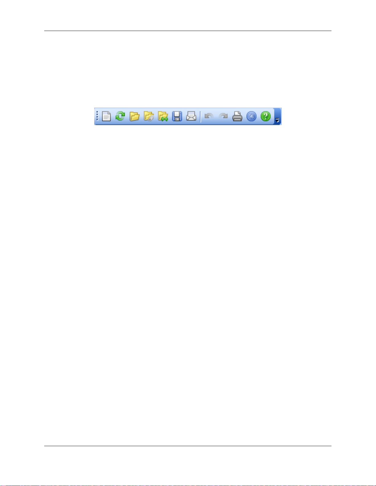
Chapter 9. File Management
With Autodesk NavisWorks Simulate 2009 you can open a wide variety of native 3D CAD file types
without having to have the CAD application on your machine. See Chapter 10, Converting Files for more
detailed information on these file formats and their options. File management all happens with the File
menu and the Standard toolbar.
File Menu
The File menu includes the following items:
• New
• Refresh
• Open
• Open URL
• Append
• Merge
• Save
• Save As
• Publish
• Print
• Print Preview
• Print Setup
• Delete
• Send
• Import
• Export
• Recent Files
• Exit
New Files
This option resets NavisWorks and closes existing files.
48
Page 61
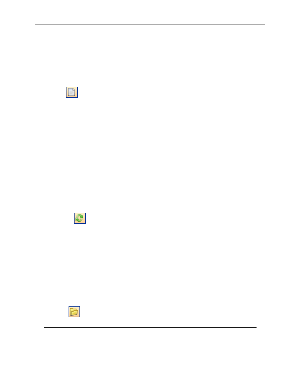
To create a new file:
• On the File menu, click New
or
• Click New on the Standard toolbar.
Refreshing Files
When working in NavisWorks, it is possible that others may be working on the CAD files you are currently
reviewing. For example, if you are coordinating various disciplines on a project, then you may have an
overall .nwf file referencing numerous design files. During the iterative stages of the project, any member
of the design team could potentially be modifying their CAD files. To ensure the data you are reviewing is
current, NavisWorks provides a refresh function to reload any files that have been modified since
commencing the review session. This feature does not reload all of the files you have loaded, merely
those modified since last opening them.
File Management
To refresh your scene with the latest versions of the currently loaded model files:
• On the File menu, click Refresh
or
• Click Refresh on the Standard toolbar.
Opening Files
With Autodesk NavisWorks Simulate 2009 you can open a wide variety of native CAD file types without
having to have the CAD application on your machine. See Chapter 10, Converting Files for more detailed
information on these file formats and their options. To open a model file:
• On the File menu, click Open
or
• Click Open on the Standard toolbar.
Note:
The standard Open dialog use of Shift and Control keys allows multiple files to be selected and
appended to the current set of models.
49
Page 62

Opening Files via URL
With Autodesk NavisWorks Simulate 2009 you can open NavisWorks published .nwd files via the Internet.
Having uploaded your .nwd file to a web server, this file can then be opened directly from within
NavisWorks. Utilizing JetStream technology, it will not be necessary for the entire file to be downloaded
before navigation can commence - between 10% and 50% will be sufficient for this, depending on the file
structure. (The greater the hierarchical structure of the model, the closer to 50% will be required for
navigation to commence. Similarly, the lesser the hierarchical structure of the model, the closer to 10%
will be required).
To open a file via a URL:
• On the File menu, click Open URL.
Appending Files
NavisWorks enables you to build up a complex scene from smaller models by appending, or uniting,
multiple model files together, which can be of any type that Autodesk NavisWorks Simulate 2009
supports. (See Chapter 10, Converting Files for more detailed information on these file formats and their
options).
File Management
Each file has its own units and when appending more files to the scene, each file is automatically scaled
to match the units of the first file loaded into the scene. Each file type has a default unit associated with it
that it uses when loading files of that type. You can change this associated unit on the Units tab of the
Global Options dialog (see “ Units Options ” for more detailed information). However, once a file is
loaded, you can change its unit scaling by clicking File Units and Transform on the Edit menu. See “
Setting a File's Units and Transform ” for more information.
The combined set of models may be published as a single NavisWorks .nwd file using the NavisWorks
Publisher. These models can then be viewed with NavisWorks Freedom™ free viewer. See “ Publishing
from NavisWorks ” for more information.
You can also save the combined set of models as an .nwf file. No geometry is saved in this format, but a
list of appended files, along with their path relative to the .nwf file is saved, along with any overrides,
comments, redlines, viewpoints or other NavisWorks specific information. See “ Saving Files ” for more
information on saving files.
To append a file:
• On the File menu, click Append
or
• Click Append on the Standard toolbar.
Note:
The standard Open dialog use of Shift and Control keys allows multiple files to be selected and
appended to the current set of models.
50
Page 63
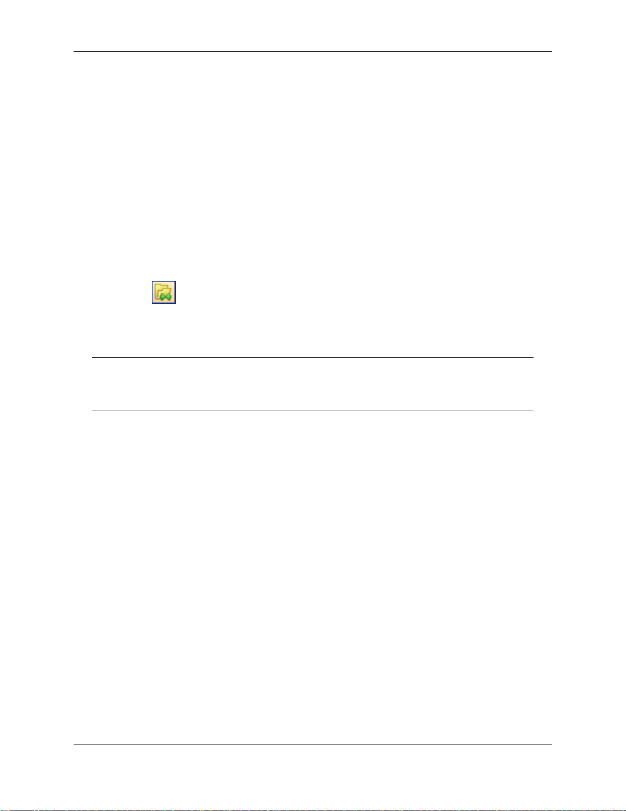
Merging Files
When merging multiple .nwf files, that each comprise the same reference files, NavisWorks will only load
a single set of the combined models, along with all review markup (such as tags, viewpoints or
comments) from each .nwf file. Any duplicate geometry or markup will be removed when merged. See “
NWF Files ” for more information on .nwf files.
Merging a file:
1. Open the first file to be merged, (see “ Opening Files ” for information on how to do this).
2. On the File menu, click Merge
or
Click Merge on the Standard toolbar.
3. Browse to and select the file, or files, to be merged.
File Management
Note:
The standard Open dialog use of Shift and Control keys allows multiple files to be selected and
merged with the currently loaded model.
Merging TimeLiner Data
If two or more merged files contain TimeLiner data, limited merging can be done with this data. Three
scenarios are handled:
• If the two TimeLiner data sets are identical, then merging of files can occur without issue.
• If the two TimeLiner data sets are completely unrelated, merging of data in this context will not be
successful.
• If the two TimeLiner data sets contain the same Primary link, then the data set with the most recent
link (i.e. the newest file date) is chosen over the other. If the Primary links are different, then the data
set with the highest number of tasks will be used, and links will be re-attached wherever possible.
For more information on TimeLiner, see Chapter 41, Overview of TimeLiner .
Saving Files
When you have finished reviewing a model or a set of models and are exiting NavisWorks, you are
prompted to save. When saving to a NavisWorks .nwf file, only a list with pointers to the files currently
loaded is saved, along with the scene's environment, the current view, clash results (if available) and
viewpoints. If you want to take a snapshot of the scene, including all geometry, then you need to publish
an .nwd file. See “ Publishing Files ” for information on how to do this.
51
Page 64

File Management
Saving a file:
1. On the File menu, click Save
or
Click Save on the Standard toolbar.
2. Enter a name and location for the file, if you wish to change the existing name.
3. Click Save to save the file or Cancel to return to NavisWorks without saving.
Saving and Renaming Files
This is exactly the same as the Save option (see “ Saving Files ”, but it gives you the opportunity to
rename the file that you are saving.
Saving a file with a new name:
1. On the File menu, click Save As.
2. Enter a new name and location to store the file.
3. Click Save to save the file or Cancel to return to NavisWorks without saving.
Publishing Files
Publishing a NavisWorks .nwd file takes a snapshot of the current scene that cannot then be changed
(i.e. files cannot be deleted from a published .nwd file). The file can also be used with the NavisWorks
Freedom™ free viewer. This command is only available if you have the NavisWorks Publisher option.
See “ Publishing from NavisWorks ” for more information.
Printing
You can print a hard copy of the current viewpoint to any printer or plotter.
Printing the Current Viewpoint
When the print option is selected, it prints the current viewpoint scaled to fit and centered on the page.
Note:
If you would prefer to export an image for printing, see “ Exporting an Image ” for more
52
Page 65
File Management
information.
Printing the current viewpoint:
1. On the File menu, click Print
or
Click Print on the Standard toolbar.
2. Check the printer settings are as required, and click OK to print the viewpoint or Cancel to return to
NavisWorks without printing anything.
Note:
The maximum image size is 2048x2048 pixels.
The Properties button controls printer-specific ink and paper settings.
Previewing Printouts
Before you print out a copy of the model you are working on, you may wish to see how it will appear.
Previewing a model before printing:
1. On the File menu, click Print Preview.
2. Use Zoom In and Zoom Out to do just that with the preview image.
3. Click Print, OK to confirm and print the image, or click Close to return to NavisWorks.
Setting up printouts
This option enables the setting up of paper size and orientation options.
Changing the print setup:
1. On the File menu, click Print Setup.
The Print Setup dialog box is displayed.
2. Make changes as required to the paper, orientation, and click the Properties button to change
printer-specific settings.
53
Page 66

3. Click OK to print the image, or click Cancel to return to NavisWorks.
Deleting Files
This option deletes the selected files from the scene. It is only available when more than one file is
appended in the scene.
Note:
You cannot delete files from within a "published" NavisWorks .nwd file (see “ Publishing Files ”.
You can only delete appended files, whether they were appended manually, or within an .nwf file.
To delete a file:
• On the File menu, click Delete.
Note:
File Management
It is not possible to undo this command.
Emailing Files
NavisWorks is a communication tool, and the Send option makes it easy for you to send your current
model along with its viewpoints. The Send option uses your current email exchange service and will
prompt you to set one up if it cannot find one.
Sending an email will first save the current working file, so you are guaranteed to always send the latest
review.
To send a file by email from within NavisWorks:
• On the File menu, click Send
or
• Click Send on the Standard toolbar.
This accesses your email package, and sends the current file as an email attachment.
Receiving 3D Mail
If an .nwf file is received, NavisWorks will search for the appended files first using the absolute path that
the sender originally saved the file with. This is useful if a team is on a local network and the files can be
found using the Universal Naming Convention (UNC). Otherwise, a team not sharing a server can
organize a project using the same file hierarchy and drive letter and NavisWorks can find the files this
way.
54
Page 67

If NavisWorks is unable to find the files, then the recipient can save the attached .nwf in a directory where
all the appended files are located. The .nwf can then look for these files relative to its own location.
This way, you are able to move a whole sub-directory from your projects directory to a completely new
location. Save the .nwf file in this new place and it will be able to search for the files from here.
Importing Files
The import option inputs Intergraph PDS review data, including:
• PDS Tags (.tag)
• PDS Display Sets (.dst)
It is also possible to import data that has been exported from previous NavisWorks sessions, including:
• Viewpoints XML (.xml)
• Search XML (.xml)
File Management
• Search Set XML (.xml)
See “ Exporting Files ” for more information on exporting data from NavisWorks.
Importing PDS Tags
Tag information from Intergraph PDS contains a unique ID, saved viewpoint and corresponding
comments. Tag information created in NavisWorks may also be exported to be used in Intergraph PDS.
See “ Exporting Files ” for more information.
Importing PDS tag files:
1. On the File menu, click Import > PDS Tags.
The Import dialog box is displayed.
55
Page 68

File Management
2. Locate and Open the .tag file to import the PDS tag data, or click Cancel to return to NavisWorks
without importing a file.
Importing PDS Display Sets
Display sets from Intergraph PDS contain detailed criteria, defining item selections. When imported into
NavisWorks, .dst files create search sets in the Selection Sets control bar. See “ Selection and Search
Sets ” for more information on search sets.
Importing PDS display sets to create search sets:
1. On the File menu, click Import > PDS Display Sets.
The Import dialog box is displayed.
56
Page 69

File Management
2. Locate and Open the .dst file to import the PDS display sets, or click Cancel to return to NavisWorks
without importing a file.
Importing Viewpoints XML
Viewpoints can be imported into NavisWorks via an .xml file, enabling you to bring viewpoints into the
current scene from another model file. For example, if you are working on different versions of the same
model, you can save viewpoints in one version of the file, export them and then import them into the other
version. See “ Saving Viewpoints ” for more information on saving viewpoints and “ Exporting Viewpoints ”
for more information on exporting viewpoints to an .xml file.
Importing viewpoints and associated data:
1. On the File menu, click Import > Viewpoints XML.
The Import dialog box is displayed.
57
Page 70

File Management
2. Locate and Open the viewpoints .xml file to import the viewpoints, or click Cancel to return to
NavisWorks without importing a file.
Importing Search XML
Search criteria can be imported into NavisWorks which populates the Find Items control bar. The search
can then be run on the current model, finding any items that match the specific criteria. See “ Finding
Items ” for more information on searching the model for items based on their properties.
Importing search criteria into the Find Items control bar:
1. On the File menu, click Import > Search XML.
The Import dialog box is displayed.
58
Page 71

File Management
2. Locate and Open the search .xml file to import the search criteria into the Find Items control bar, or
click Cancel to return to NavisWorks without importing a file.
Importing Search Sets XML
Search sets can be imported into NavisWorks which populates the Selection Sets control bar with
pre-defined search sets. Selecting an imported search set will define the current Find Items criteria and
search the current model accordingly. See “ Finding Items ” for more information on searching the model
for items based on their properties.
Importing search sets into the Selection Sets control bar:
1. On the File menu, click Import > Search Sets XML.
The Import dialog box is displayed:
59
Page 72

File Management
2. Locate and Open the search sets .xml file to import the search sets into the Selection Sets control
bar, or click Cancel to return to NavisWorks without importing a file.
Exporting Files
The export option outputs the current viewpoint in one of four ways:
• Piranesi EPix format (.epx)
• Windows Bitmap format (.bmp)
• Portable Network Graphics format (.png)
• JPEG format (.jpg)
• Rendered image formats (various)
It is also possible to export an animation to:
• Windows AVI (.avi)
60
Page 73

File Management
Or, as a sequence of individual frames, to:
• JPEG format (.jpg)
• Portable Network Graphics format (.png)
• Windows Bitmap (.bmp)
The export option additionally outputs a variety of review data, including:
• PDS Tags (.tag)
• Viewpoints XML (.xml)
• Current Search XML (.xml)
• Search Sets XML (.xml)
• Viewpoint Report HTML (.html)
The export option outputs a number of additional review file types:
• Autodesk DWF (.dwf)
• Google Earth KML (.kml)
Exporting to a Piranesi EPix Format
Exporting an .epx file for rendering in Informatix’s Piranesi:
1. On the File menu, click Export > Piranesi EPix.
2. Click the Browse button to locate a destination and enter a new filename to export, if you wish to
change from the existing filename and location.
3. Select the sizing options for the file to be exported. (See “ Controlling the Size of an Image ” for more
details).
4. Click Save to export the file, or Cancel to return to NavisWorks.
Exporting an Image
Exporting to a Bitmap, PNG or JPEG
1. Display the view you want to export in the main navigation window, and click Export > Image on the
61
Page 74
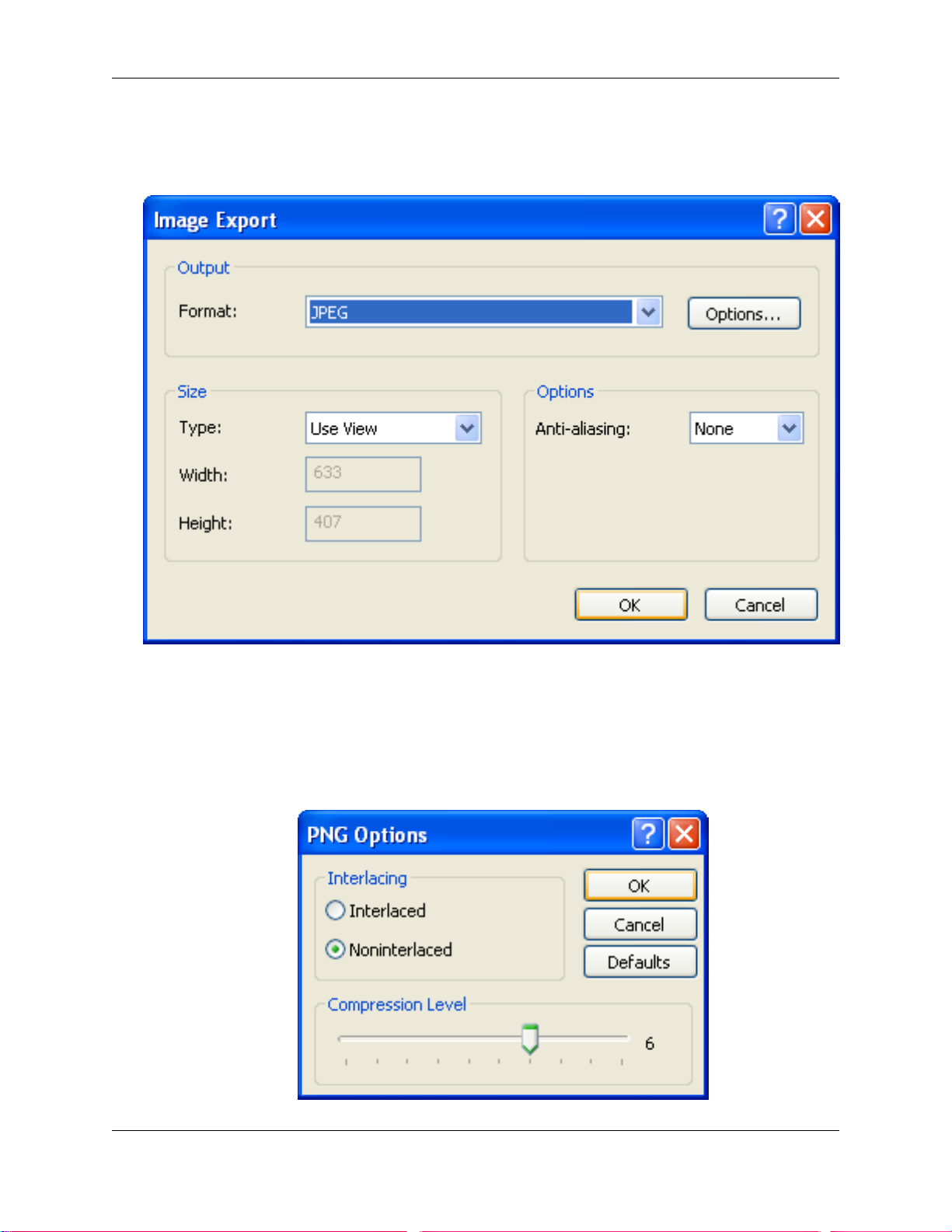
File Management
File menu.
The Image Export dialog box is displayed.
2. Select the format of the image you wish to export:
• Windows Bitmap
• Portable Network Graphics (PNG)
Select Interlacing and Compression options from the PNG Options dialog box:
62
Page 75

File Management
• JPEG
Select Compression and Smoothing options from the JPEG Options dialog box:
3. Select the sizing options for the file to be exported. (See “ Controlling the Size of an Image ” for more
details).
4. Click OK to continue, or click Cancel to return to NavisWorks without exporting an image.
5. Enter a new name and location to store the file.
6. Click Save to export the file, or Cancel to return to NavisWorks.
Exporting an Animation
Exporting an animation to an .avi file, or a sequence of image files:
1. With an animation selected, on the File menu, click Export > Animation.
The Animation Export dialog box will be displayed.
63
Page 76
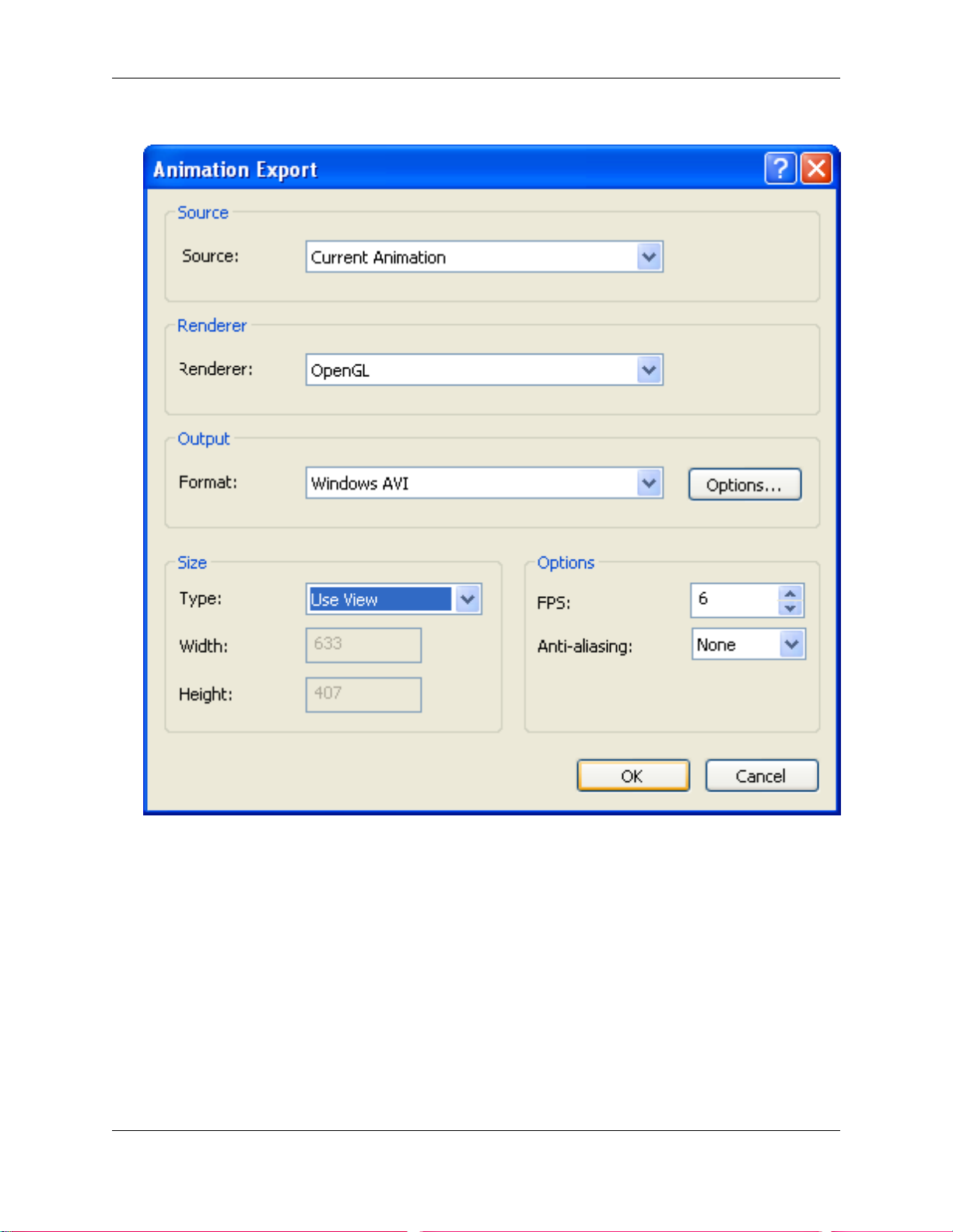
File Management
2. Select the Source from which you wish to export the animation.
Current Animation - the currently selected viewpoint animation.
TimeLiner Simulation - the currently selected TimeLiner sequence.
Current Animator Scene - the currently selected object animation.
3. Select the Renderer with which you wish to render the exported animation.
OpenGL - quickly renders your animation; this option is also ideal for previewing
animations.
Presenter - use this option when you require the highest rendering quality.
64
Page 77

File Management
4. Select the Format in which you wish the output to be exported in:
• Windows AVI
Click Options... to select the Video Compression you require.
Note:
Clicking Compression will open a standard Windows™ dialog box that allows you to choose
which codec to use, as well as its configuration. Only those codecs currently installed will be
shown and the PC that the .avi file will be run on will also need the same codec installed.
• JPEG (sequence of static images, taken from individual frames)
Click Options... to set the Compression and Smoothing levels you require.
• PNG (sequence of static images, taken from individual frames)
Click Options... to set the Interlacing and Compression levels you require.
• Windows Bitmap (sequence of static images, taken from individual frames)
5. Select the sizing options for the file to be exported. See “ Controlling the Size of an Image ” for more
details.
6. For AVI files, you should also enter the number of frames per second (FPS) you require.
Note:
The higher the FPS, the smoother the animation will be. However, using a high FPS will
considerably increase the rendering time. 10-15 fps should be enough for a good quality AVI.
7. Click OK to continue, or Cancel to return to NavisWorks.
8. Enter a new name and location to store the file(s).
Note:
For image sequences, the name will contain the first integer of a 'counter', e.g. 001. Subsequent
frames will be automatically incremented by one, e.g. 002, 003, 004 and so on.
9. Click Save to export the file(s), or Cancel to return to NavisWorks.
Controlling the Size of an Image
65
Page 78
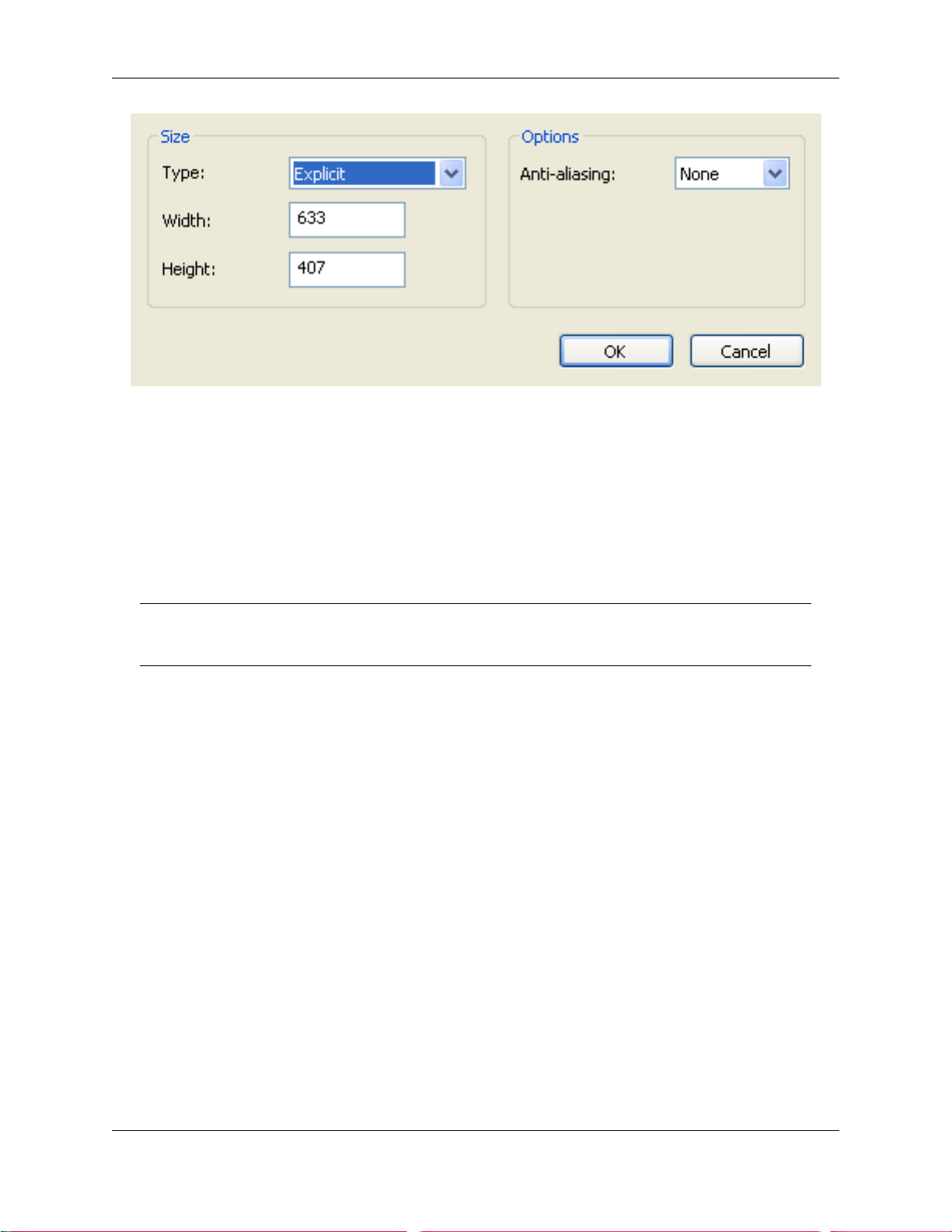
File Management
The size of the exported image/animation can be set in various ways:
Explicit allows you full control of the width and height (the dimensions are in pixels).
Aspect Ratio allows you to set the height, and the width is automatically calculated from the aspect ratio
of your current view.
Use View takes the width and height of your current view.
Anti-Aliasing smoothes the edges of the exported images. The higher the number, the smoother the
image, but the longer they take to export. 4x should be adequate for most situations.
Note:
There is a maximum size of 2048 x 2048 pixels, for NavisWorks OpenGL output.
Exporting PDS Tags
Exporting PDS tags
1. On the File menu, click Export > PDS Tags.
2. Enter a new filename and location, if you wish to change from those suggested.
3. Click Save to export the .tag file, or Cancel to return to NavisWorks.
Exporting Viewpoints
Viewpoints can be exported from NavisWorks to an .xml file. These viewpoints contain all associated
data, including camera positions, sections, hidden items and material overrides, redlines, comments, tags
and collision detection settings.
Once the viewpoint data is exported to this text-based file format, it can either be imported into other
NavisWorks sessions, or it can be accessed and used in other applications. For example, you may want
to set up the same viewpoints in your CAD application.
66
Page 79

Exporting viewpoints:
1. On the File menu, click Export > Viewpoints XML.
2. Enter a new filename and location, if you wish to change from those suggested.
3. Click Save to export the .xml file, or Cancel to return to NavisWorks.
Exporting Current Search
The search criteria specified in the Find Items dialog box can be exported to an .xml file. This can then be
imported into other NavisWorks sessions. For example, if you have specified a complicated search
criteria, containing various logic statements, that relates to all projects you work on, then this feature
allows you to specify it once and use it on all projects.
Exporting current search:
File Management
1. From the File menu, choose Export > Current Search XML.
2. Enter a new filename and location, if you wish to change from those suggested.
3. Click Save to export the .xml file, or Cancel to return to NavisWorks.
Exporting Search Sets
Saved search sets can be exported from NavisWorks as an .xml file. These can then be imported into
other NavisWorks sessions and re-used. For example, if you have a number of generic searches that you
perform on all of your projects, this feature allows you to specify the searches once and use them on all
projects.
Exporting search sets:
1. On the File menu, click Export > Search Sets XML.
2. Enter a new filename and location, if you wish to change from those suggested.
3. Click Save to export the .xml file, or Cancel to return to NavisWorks.
Exporting Viewpoints Report
An .html file can be exported containing a JPEG of all of the saved viewpoints and associated data,
including camera position and comments.
67
Page 80

Note:
To customize the appearance or layout of the html file, you will need to edit the
viewpoints_report_lang.xsl file, where lang is a code representing your language. The installed
file is located in the stylesheets subdirectory of the NavisWorks install directory. You can copy
the edited file to the stylesheets subdirectory of any of the NavisWorks search directories.
See “ Search Directories ” for more information.
Exporting viewpoints report:
1. On the File menu, click Export > Viewpoints Report HTML.
2. Enter a new filename and location, if you wish to change from those suggested.
3. Click Save to export the report, or Cancel to return to NavisWorks.
Exporting to Autodesk DWF
File Management
Autodesk DWF files can be exported from NavisWorks. The exporter creates a .dwf file containing:
• All geometry
• All materials
• Per-vertex colors
• Properties (where available)
Exporting a DWF file:
1. On the File menu, click Export > Autodesk DWF.
2. Enter a new filename and location, if you wish to change from those suggested.
3. Click Save to export the file, or Cancel to return to NavisWorks.
Exporting to Google Earth KML
Google Earth KML files can be exported from NavisWorks. The exporter creates a compressed KML file
with the extension .KMZ and supports the export of:
• Triangles
• Lines
68
Page 81

File Management
• Materials (colour and flat transparency only)
• Viewpoints (adjustments may occur due to Google Earth limitations)
• Model Hierarchy
• Hyperlinks (currently only URLs work correctly in Google Earth)
Exporting to Google Earth KML files:
1. On the File menu, click Export > Google Earth KML.... This brings up the following dialog box.
2. Select Export model relative to terrain height to put Google Earth in a mode where all heights are
measured from the surface of the ground. When this is off all heights are measured from sea-level.
Note:
69
Page 82

File Management
When positioning a model relative to sea level, the height of the Google Earth reference points
must also be measured relative to sea level. When positioning a model relative to the ground, the
Google Earth reference points must be measured relative to the ground.
Google Earth always places new placemarks at an altitude of zero, irrespective of whether that is
relative or absolute.
3. Collapse on export allows different levels of collapsing parts of the model hierarchy in the exported
file.
• None ensures the whole heirarchy is exported
• All objects collapses everything into one node
• Files collapses each file into one node
• Layers collapses each layer into one node
4. Limit number of Polygons should be enabled to restrict the amount of geometry exported into the
output file. Geometry is selected on the basis of taking the most obvious objects in preference to the
fine detail. If the exported file is too large for Google Earth to display, try enabling this and reducing
the number of polygons. View, Scene Statistics in NavisWorks shows the number of triangles
and/or lines in the current project. By setting a polygon limit you are choosing to export only some of
these items.
Note:
Google Earth's ability to handle large numbers of polygons is far more limited than NavisWorks.
Hence it is worth noting that currently Google Earth will consider 1,000,000 polygons as being a
big model.
5. The Origin position values are the first pair of reference points on the Google Earth surface, and
must always be defined. The NavisWorks reference point will always be positioned to exactly overlay
the Google Earth reference point.
Second and Third reference points can be used, and if enabled then the position and orientation of
the model can be more accurately defined.
6. Use the Import buttons to read-in saved placemark locations from KML files exported from Google
Earth.
The Origin Import button differs slightly from the other two; if the KML file contains multiple
placemarks, this button will offer the user the choice of importing second and third reference points if
available. The other two buttons will only import a single reference point.
7. The Pick buttons allow the reference point locations to be selected in the main 3D view.
These points must be visible in the main 3D view prior to exporting, as once the KML Options dialog
box is open you will not be able to navigate before picking.
Note:
You may wish to use View, Split to split the main 3D view enabling you to have separate views of
each reference point.
70
Page 83

Quitting NavisWorks
Quitting NavisWorks:
1. On the File menu, click Exit
2. If the model has been changed since opening it, NavisWorks will ask you whether you want to save
any changes. Respond appropriately and NavisWorks will then close.
File Management
71
Page 84

Chapter 10. Converting Files
With Autodesk NavisWorks Simulate 2009 you can open a wide variety of native CAD file types without
having to have the CAD application on your machine. Files read by NavisWorks include .dwg, .dgn, .dxf
and Inventor. For a full list of CAD files that NavisWorks can open, please refer to the web site
www.autodesk.com/navisworkssimulate. This site will also explain which entities are read by NavisWorks
and which are ignored, as well as any object property information that is converted. It is possible to load
multiple files of different formats into the same scene in NavisWorks and set their units and origins
appropriately. There are also a number of options to help optimize native CAD file reading.
In addition to these native CAD files, Autodesk NavisWorks Simulate 2009 also reads its own native .nwc
(NavisWorks Cache), .nwf (NavisWorks File review) and .nwd (published NavisWorks Data) file formats.
Some file formats, such as those from Autodesk's Viz and Graphisoft's ArchiCAD cannot be read directly
by NavisWorks but there are exporters available to export to the NavisWorks .nwc file format from these
applications. See “ File Exporters ” for more details.
File Readers
As well as the NavisWorks file formats, .nwf, .nwd and .nwc, NavisWorks can open a variety of native
CAD and scanning applications' formats:
• .dwg
• Bentley AutoPLANT .dwg, .mdb
• .dxf
• .dwf
• .3ds
• .dgn
• .man
• PDS files
• .iges
• .step
• Inventor parts & assemblies
• VRML world files (.wrl;.wrz)
• Riegl Scan data (.3dd)
• Faro Scan data (.fls, .flw, .iQscan;.iQmod;.iQwsp)
• Leica Scan data (.pts;.ptx)
• Z+F Scan data (.zfc;.zfs)
• ASCII Laser Scan data (.asc;.txt)
72
Page 85

• STL Stereolithography data (.stl)
• AVEVA Review (.rvm)
• IFC files (.ifc)
• Sketchup (.skp)
NWF Files
.nwf files can be saved by NavisWorks in order to save a current review of the scene. No geometry is
saved in this format, but a list of appended files, along with their path relative to the .nwf file is saved,
along with any overrides, comments, redlines, viewpoints or other NavisWorks specific information. .nwf
files are useful when the CAD files are still changing throughout the design period, as the latest files are
loaded each time the .nwf file is opened.
NWD Files
.nwd files are files published by NavisWorks Publisher and are snapshots of the model at a certain time.
See “ Publishing from NavisWorks ” for more information on this.
Converting Files
NWD Options
NavisWorks allows you to enable and disable geometry compression and select whether the precision of
certain options should be reduced when saving (or publishing) .nwd files. Geometry compression results
in less memory being required and therefore smaller .nwd files.
Setting NWD options:
1. On the Tools menu, click Global Options.
2. Expand the Model node in the Options Editor dialog box, and click the NWD option.
The NWD page is displayed.
73
Page 86

Converting Files
3. Clear the Enable check box if you do not require any geometry compression.
4. Select the Coordinates check box if you want to reduce the precision of coordinates.
Enter the value to which you wish coordinates to be precise to in the Precision box. The larger the
value, the less precise coordinates will be and the smaller the .nwd will be.
5. Select the Normals check box to reduce the precision of normals.
6. Select the Colors check box to reduce the precision of colors.
7. Select the Texture Coordinates check box to reduce the precision of texture coordinates.
8. Click OK to set these options or Cancel to exit the dialog without setting them.
NWC Files
Cache files (.nwc) are used when reading native CAD files, such as files from AutoCAD or MicroStation.
By default, when Autodesk NavisWorks Simulate 2009 opens a native CAD file, it first checks in the same
directory whether there is a NavisWorks cache file present with the same name as the CAD file but with a
.nwc extension. If there is, and this cache file is newer than the native CAD file, then NavisWorks will
open this file instead as it has already been converted to NavisWorks format and therefore will open much
quicker. If, however, there is no cache file present, or the cache file is older than the native CAD file, then
NavisWorks will have to open the CAD file and convert it. At this point, it will by default write a cache file
in the same directory and with the same name as the CAD file, but with the .nwc extension, for speeding
up the opening of this file in future.
See “ File Exporters ” for more information on why you might want to use the .nwc file exporters, which
CAD applications you can export from and how.
74
Page 87

Converting Files
NWC Options
NavisWorks allows you to enable and disable the reading and writing of cache files.
This describes the default process. The options here enable you to enable and disable the reading and
writing of cache files. For example, you may want to disable reading cache files to ensure that
NavisWorks converts every native CAD file each time it is read, even though this is a slower process.
Also, you may want to disable the writing of cache files in order to save on disk space and clutter, even
though the cache files are generally many times smaller than the original native CAD files.
Setting NWC options:
1. On the Tools menu, click Global Options.
2. Expand the Model node in the Options Editor dialog box, and click the NWC option.
The NWC page is displayed.
3. Clear the Read Cache check box if you want to ignore any existing caches when opening a native
CAD file.
4. Clear the Write Cache check box if you do not wish to write a cache file the next time a native CAD
file is loaded.
5. Clear the Enable check box if you do not require any geometry compression when .nwc files are
written.
6. Select the Coordinates check box if you want to reduce the coordinate precision.
Enter the value to which you want coordinates to be precise to in the Precision box. The larger the
75
Page 88

value, the less precise coordinates will be and the smaller the .nwc will be.
7. Select the Normals check box to reduce the precision of normals.
8. Select the Colors check box to reduce the precision of colors.
9. Select the Texture Coordinates check box to reduce the precision of texture coordinates.
10. Click OK to set these options or Cancel to exit the dialog without setting them.
DWG and DXF Files
NavisWorks's .dwg and .dxf file reader uses Autodesk's ObjectDBX™ technology and so is guaranteed to
read all object geometry and information for those third party applications that utilize the ObjectDBX
Framework.
The reader currently supports all surface (shaded) entities (3D faces, rectangular meshes, polyface
meshes, circles, extruded lines and so on), including Proxy Graphics and custom objects such as ACIS
based entities (3D Solid, Region), lines, points and snap points. Complex entities (shapes, dimensions,
text) are not supported. The structure of the drawing is preserved including xrefs, blocks, inserts,
AutoCAD color index, layers, views and active viewpoint. Entities are colored using the AutoCAD Color
Index (ACI), so will match those in an AutoCAD "shaded" view.
Converting Files
There is also an .nwc file exporter for AutoCAD - see “ AutoCAD .nwc Exporter ” for more details.
Note:
The reader supports files from all products based on AutoCAD 2009 and earlier.
Supported Entities
• All 2D and 3D geometry, including arcs, lines, polylines with non-zero thickness, ACIS objects (regions
and solids), polygon and polyface meshes, 3D faces and surfaces.
• Points and snap points.
• Lines, polylines, circles, arcs with zero thickness.
• Named views.
• Layers.
• Colors.
• Blocks, inserts and multiple inserts.
• Groups.
• External references (xrefs).
• Hyperlinks.
• Text or multi-line text.
76
Page 89

• Entity handles.
• Attributes.
• Textures.
• File properties.
Unsupported Entities
• Lights
• Splines
• Multi-lines
• Linetypes
• Dimensions and leaders
• Raster bitmaps
Converting Files
• Construction lines (xlines and rays)
• Hatching
DWG and DXF File Reader Options
Setting the .dwg and .dxf file reader options:
1. On the Tools menu, click Global Options.
2. Expand the File Readers node in the Options Editor dialog box, and click the DWG/DXF/SAT
option.
The DWG/DXF/SAT page is displayed.
77
Page 90

Converting Files
3. Enter the Faceting Factor (the value must be greater than 0). The higher the value, the more
NavisWorks will facet rounded entities and, therefore, the smoother they will appear. See Faceting
Factor for more information.
4. Enter the Max Facet Deviation. This will facet entities to within the specified tolerance. See Max
Facet Deviation for more information.
5. Select the Split by Color check box if you want to be able to select parts of compound entities in
NavisWorks. For example, a window object from Architectural Desktop may be split into a frame and
a pane. If this check box is not selected, then you will only be able to select the window object as a
whole, whereas if you select this check box, you will be able to select the individual pane and frame.
However, the names of the pane and frame will be based on their color.
6. From the Default Decimal Units drop-down list, choose the type of units that NavisWorks will use
when opening .dwg and .dxf files that were created with decimal drawing units. Note that .dwg and
.dxf files do not specify the units they were created in. If the units turn out to be wrong, they can be
easily changed using the File Units and Transform option (see “ Setting a File's Units and
Transform ” for more details).
7. Select the Merge 3D Faces check box if you want to reduce the complexity of the model as seen in
the selection tree by interpreting adjoining faces with the same color, layer and parent as a single
item. To keep the entities as separate items in NavisWorks, clear the check box.
8. Select the Merge Lines check box if you want to reduce the complexity of the model as seen in the
selection tree by interpreting joining lines with the same color, layer and parent as a single item. To
keep the entities as separate items in NavisWorks, clear the check box.
9. Select the Convert Off check box if you want to read layers that are switched off in .dwg and .dxf
files. They will be converted but hidden in NavisWorks.
10. Select the Convert Frozen check box if you want to read layers that are frozen in .dwg and .dxf files.
78
Page 91

Converting Files
They will be converted but hidden in NavisWorks.
11. Select the Convert Entity Handles check box if you want to read entity handles as a property
attached to the item in NavisWorks.
12. Select the Convert Groups check box if you want to retain the groups from .dwg and .dxf files,
adding another selection level to the selection tree. See Chapter 13, Selecting Items for more
information on selecting objects and the selection tree.
13. Select the Convert XRefs check box if you want to convert any external reference files contained
within the .dwg file. Clear this check box to get more control over which files you append into
NavisWorks.
14. Select the Merge XRef Layers check box if you wish to merge the layers of external reference files
into those of the main .dwg file. Leaving this unchecked will keep the external reference file separate
within the selection hierarchy of NavisWorks.
15. Select the Convert Views check box if you want to convert the named views from the file into
NavisWorks viewpoints.
16. Select the Convert Points check box if you want to read any points from .dwg and .dxf files. See “
Display Options ” for more information on how to display these in NavisWorks.
17. Select the Convert Lines check box if you want to read any lines and arcs from .dwg and .dxf files.
See “ Display Options ” for more information on how to display these in NavisWorks.
18. Select the Convert Snap Points check box if you want to read any snap points from .dwg and .dxf
files. See “ Display Options ” for more information on how to display these in NavisWorks.
19. The Loader Version drop-down list allows selection of which version of ObjectDBX is used when
loading AutoCAD files. This allows you to select support for the correct version of object enablers that
may be used within the file. Please note that once any particular version of ObjectDBX is loaded,
which occurs during reading of a .dwg or .dxf file, that the version in use will not change until
NavisWorks is restarted.
20. Select the Load Material Definitions check box if you want to load material definitions into
NavisWorks from Autodesk Architectural Desktop .dwg files.
21. Select the Use ADT Standard Configuration check box to force reading of Autodesk Architectural
Desktop .dwg files using the Standard display configuration. If unchecked, geometry and materials
will be read in according to whether they are displayed in the currently saved display configuration.
22. Select the Convert Hidden ADT Spaces check box to perform conversion of space objects that lack
any visible 3D geometry in ADT (for example if they lack floor or ceiling thicknesses). This will result
in corresponding hidden objects appearing in NavisWorks. The normal behavior for space objects
that have visible 3D geometry in ADT is unaffected.
23. The Material Search Paths edit box may contain file paths in a semi-colon separated list that will be
searched for texture files used in Autodesk Architectural Desktop materials. Default Autodesk paths
are automatically searched and need not be entered.
24. The Render Type drop-down list enables you to specify the render style used for objects when
loading .dwg files.
Selecting the Automatic option means NavisWorks will use the render style saved in the .dwg file. If
geometry does not appear correctly, adjust the render style by selecting the Rendered, Shaded, or
Wireframe option from the drop-down list, as appropriate
79
Page 92
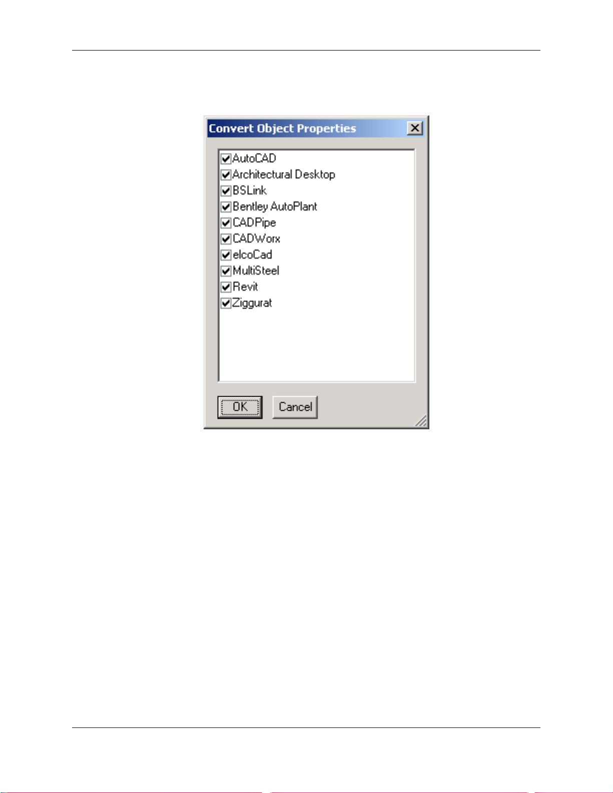
Converting Files
25. Clicking the Advanced button will open a dialog which giving you the option to read object
information from various third party applications that are built on AutoCAD.
Check those applications you wish to read information from.
26. Click OK to set these options or Cancel to exit the dialog without setting them.
DWF Files
Autodesk's DWF (Design Web Format) was specifically developed by Autodesk as a file format for
architects, engineers, and GIS professionals to share design data. The NavisWorks file reader reads all
3D geometry, as well as textures and properties. A full list is given below.
Supported Entities
• All 3D geometry
• Texture maps.
• Texture coordinates
• Colors (per-vertex, per-face)
• Property fields
80
Page 93
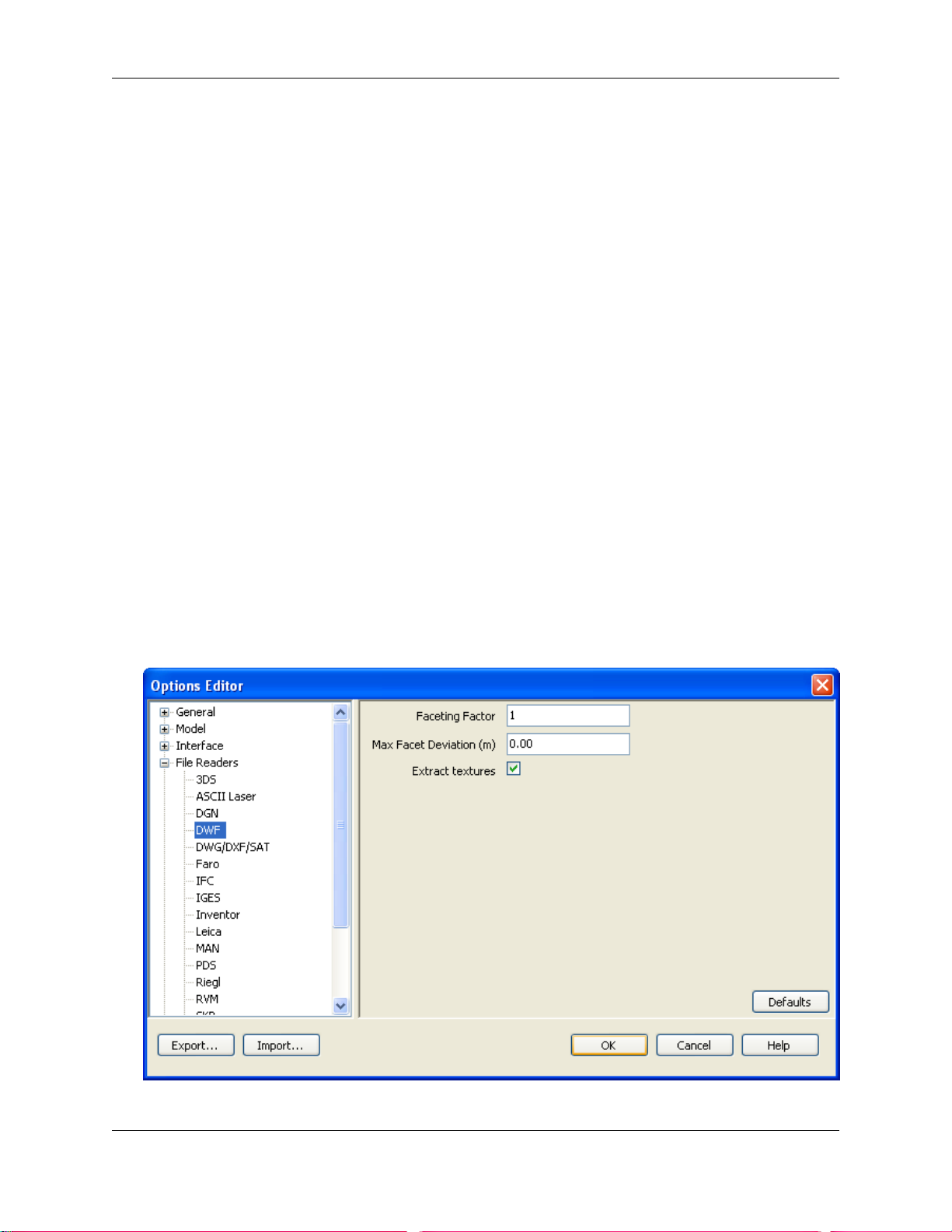
Converting Files
• Categories
Unsupported Entities
• 2D lines/plot sections
• Thumbnails
• Marked-up sketches
• More than one 3D section per file (any others are ignored)
• NURBS Surfaces
• Cameras
DWF File Reader Options
Setting the .dwf file reader options:
1. On the Tools menu, click Global Options.
2. Expand the File Readers node in the Options Editor dialog box, and click the DWF option.
The DWF page is displayed.
3. Enter the Faceting Factor (the value must be greater than 0). The higher the value, the more
81
Page 94

NavisWorks will facet rounded entities and therefore the smoother they will appear. See Faceting
Factor for more information.
4. Enter the Max Facet Deviation. This will facet entities to within the specified tolerance. See Max
Facet Deviation for more information.
5. Select the Extract textures check box to load in textures and environment maps associated with the
file. Environment maps will not automatically be set in the scene, and will need to be manually set up
in Presenter.
6. Click OK to set these options or Cancel to exit the dialog without setting them.
Bentley AutoPLANT Files
Bentley AutoPLANT is based on AutoCAD and as such uses the .dwg file format to store model
geometry. Any settings related to the .dwg file format also affect files from AutoPLANT.
AutoPLANT Object Properties can be stored in external database .mdb files, and NavisWorks supports
these files through the DataTools functionality. By default NavisWorks and DataTools are both set up to
support AutoPLANT .dwg and .mdb files, and will be looking for Equipment, Nozzle and Piping Data.
Converting Files
Setting DataTools:
1. On the Tools menu, click File Options.
2. In the File Options dialog box, click the DataTools tab.
82
Page 95
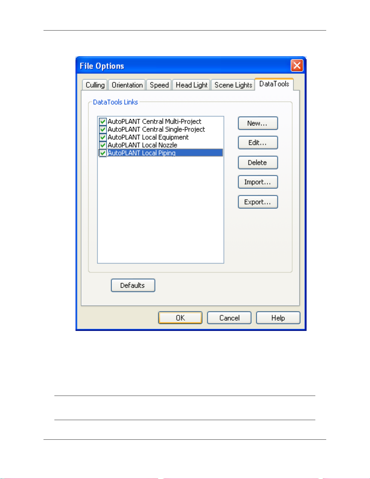
Converting Files
The settings for these three sets of data can be edited by selecting the appropriate item in the list
and clicking on the Edit button. See Chapter 25, DataTools for more information.
For AutoPLANT properties to be loaded correctly an .mdb file must be located in the same directory
as the .dwg file, with the same filename followed by the .mdb extension. If this file exists, NavisWorks
will automatically pick it up and use it to show appropriate properties in the Properties window.
Note:
NavisWorks does not currently support per-project properties.
83
Page 96

3DS Files
3DS is a common file format that is supported by many CAD applications. The NavisWorks file reader
reads all 2D and 3D geometry as well as texture maps. The hierarchy defined by the keyframe data from
keyframe 0 is preserved, including instancing. Entities are positioned based on keyframe 0.
Autodesk NavisWorks Simulate 2009 does not read .max files, but instead has exporters for Viz and Max.
Entity support is the same as for the 3ds reader. See “ Viz and Max .nwc Exporter ” for more information.
Textures from .3DS files come through into NavisWorks Presenter, though you should bear in mind that
.3DS files contain file names in the 8.3 DOS format only and that various formats are not yet supported in
Presenter (see below).
Supported Entities
• All 2D and 3D geometry
• Cameras
• Groups
• Texture maps in the formats: 8-bit color-mapped, 16-bit and 24-bit true color, uncompressed or Run
Length Encoded .tga, .bmp, .jpg, .lwi (LightWork Image).
Converting Files
• Colors (from material color, not wireframe color - ambient, diffuse, shininess, transparency and self
illumination)
Unsupported Entities
• Keyframes (objects are currently taken from keyframe 0)
• Texture maps in the formats: gray-scale .tga, .tif, .gif, .png.
• Other maps (e.g. opacity maps, reflections etc.)
• Wireframe meshes
• Lines, splines
• Points
• Background images
3DS File Reader Options
Setting the .3ds file reader options:
1. On the Tools menu, click Global Options.
2. Expand the File Readers node in the Options Editor dialog box, and click the 3DS option.
84
Page 97

The 3DS page is displayed.
Converting Files
3. Select the Convert Hidden check box if you want to read hidden entities from the .3ds file. They will
be converted but hidden in NavisWorks.
4. The paths of texture map files are not stored with the texture maps in the model so enter a
semi-colon separated list of paths in Bitmap File Search Paths that the reader will search in when it
finds texture maps in the model.
5. From the Default Units drop-down list, choose the type of units that NavisWorks will use when
opening .3ds files. If the units turn out to be wrong, the model can be easily rescaled using the File
Transform option (see “ Setting a File's Units and Transform ” for more details).
6. Click OK to set these options or Cancel to exit the dialog without setting them.
DGN and PRP Files
NavisWorks can read 3D .dgn and .prp files from Bentley's MicroStation, but does not support .cel files or
2D .dgn files. Reference files and instances of cells are respected and the selection tree reflects this file
structure.
There is also an .nwc file exporter for MicroStation - see “ MicroStation .nwc Exporter ” for more details.
Note:
The reader supports files from MicroStation 95, SE and /J. It does not support MicroStation
Modeller and any versions of MicroStation before 95.
The DGN reader additionally does not support auxiliary coordinate systems.
85
Page 98

Converting Files
Supported Entities
• All 2D and 3D geometry including shapes, complex shapes, meshes, cones, surfaces, B-spline
boundaries, solids, SmartSolids and Feature Solids, lines, arcs and ellipses.
• Splines and B-spline curves.
• Lights.
• Levels.
• Cells and shared cells and their instancing.
• Colors and ambient, diffuse and shininess properties of materials from .pal and .mat palette and
material files.
• Texture maps.
• Reference files including aliases.
• Dynamic drawing of parametric models when loading/exporting DGN and PRP files.
• 3D text used for notes and labels is now converted and displayed by default.
• Family, Part and Texture information from TriForma, and PDS object information from .drv files.
• DMRS and database linkage and association ID's.
Unsupported Entities
• Raster bitmaps.
• Dimensions and leaders.
DGN File Reader Options
Setting the .dgn file reader options:
1. On the Tools menu, click Global Options.
2. Expand the File Readers node in the Options Editor dialog box, and click the DGN option.
The DGN page is displayed.
86
Page 99

Converting Files
3. Enter the Faceting Factor (the value must be greater than 0). The higher the value, the more
NavisWorks will facet rounded entities and therefore the smoother they will appear. See Faceting
Factor for more information.
4. Enter the Max Facet Deviation. This will facet entities to within the specified tolerance. See Max
Facet Deviation for more information.
5. Select the Convert Hidden Items check box if you want to read hidden entities from the .dgn file.
They will be converted but hidden in NavisWorks.
6. Select the Show Hidden Items check box if you want to show all entities in the .dgn file whether they
are set as hidden or not. This option will only work if Convert Hidden Items is also selected.
7. Select the Convert Lines and Arcs check box if you want to read lines, splines, curves, arcs, circles
or ellipses from the .dgn file.
8. Select the Merge Lines and Arcs check box if you want to reduce the complexity of the model as
seen in the selection tree by interpreting adjoining lines etc. with the same color, level and parent as
a single item. Clear this check box if you want to leave these elements as separate items in
NavisWorks.
9. Select the Convert Text check box if you want to read text from the .dgn file. Text will be converted
into smart tags in NavisWorks.
10. Enter the Shape Merge Threshold into the box. See Shape Merge Threshold for more information
on Shape Merge Threshold.
11. Select the Convert References check box if you want to read reference files from the .dgn file.
12. Select the Ignore Unres. References check box if you want to ignore unresolved reference files
from the .dgn file. If this check box is cleared, then you will be presented with a dialog to find any
unresolved reference files at a run time.
87
Page 100

Converting Files
13. Select the Use Level Symbology check box if you want to use the level symbology from
MicroStation so that items in NavisWorks take their color from level rather than the default element
color in MicroStation.
14. MicroStation has the concept of a “global origin”, which is where (0, 0, 0) is located (assuming there
are no active ACSs). Changing this global origin in MicroStation doesn't actually move anything; it
simply changes the reporting of coordinates. However, when attaching references in MicroStation,
you can tell it to align global origins.
Select the Align Global Origins check box if you want to use this functionality when loading DGN
files into NavisWorks. When two DGN files are appended together with this check box selected, their
global origins will be in the same place.
15. Select the Use Materials check box if you want to use MicroStation's materials in place of its colors
in NavisWorks. If you choose not to export materials, NavisWorks will assign the same colors as in
the MicroStation scene. Assigning materials will assign the same textures, diffuse, ambient and
specular colors to the elements as in the MicroStation scene.
16. Enter a semi-colon separated list of paths in Material Search Paths that the reader will search in for
MicroStation palette (.pal) and material (.mat) files in order to convert its materials.
17. Select the Convert PDS Data check box if you want to read object information from Intergraph's
Plant Design System™ while reading the .dgn files. PDS information is read from Intergraph's .drv
files. NavisWorks looks for a .drv file with the same base name as the .dgn file in the same directory.
18. Select the Convert TriCAD Data check box if you want to read object information from Triplan's
TriCAD™ while reading the .dgn files.
19. Select the Convert TriForma Data check box if you want to read object information from Bentley's
TriForma™ while reading the .dgn files.
20. Enter a semi-colon separated list of paths in TriForma Dataset Search Paths that the reader will
search for Triforma data set files. User defined datasets will need their directories adding to this list.
21. Enter a View Number if you want to use a specific view for loading. The loader will use the level
visibility of this view when converting items. If you want to use the first active view, set this value to 0.
22. Click OK to set these options or Cancel to exit the dialog without setting them.
MAN Files
NavisWorks can read .man files from Informatix's MicroGDS™ version 6.0 or later. MicroGDS™ projects
are not supported. The workaround is to first export the desired project window as a .man file.
MicroGDS Renderer materials are shown in their flat-shaded colors in NavisWorks Shaded display. In Full
Render or Presenter rendering, the full shaders are used. Only the standard LightWorks shaders are
available - those which are unique to MicroGDS are not available inside NavisWorks - a compromise is
made for shaders which are not available inside NavisWorks.
• height band color shader is treated as plain grey
• wrapped random color shader is treated as a plain color using the flat-shaded color from MicroGDS
• wrapped stencil transparency is ignored
88
 Loading...