

Page 1

Autodesk Navisworks Manage 2010
User Guide
March 2009
Page 2

©
2009 Autodesk, Inc. All Rights Reserved. Except as otherwise permitted by Autodesk, Inc., this publication, or parts thereof, may not be
reproduced in any form, by any method, for any purpose.
Certain materials included in this publication are reprinted with the permission of the copyright holder.
Trademarks
The following are registered trademarks or trademarks of Autodesk, Inc., in the USA and other countries: 3DEC (design/logo), 3December,
3December.com, 3ds Max, ADI, Alias, Alias (swirl design/logo), AliasStudio, Alias|Wavefront (design/logo), ATC, AUGI, AutoCAD, AutoCAD
Learning Assistance, AutoCAD LT, AutoCAD Simulator, AutoCAD SQL Extension, AutoCAD SQL Interface, Autodesk, Autodesk Envision, Autodesk
Insight, Autodesk Intent, Autodesk Inventor, Autodesk Map, Autodesk MapGuide, Autodesk Streamline, AutoLISP, AutoSnap, AutoSketch,
AutoTrack, Backdraft, Built with ObjectARX (logo), Burn, Buzzsaw, CAiCE, Can You Imagine, Character Studio, Cinestream, Civil 3D, Cleaner,
Cleaner Central, ClearScale, Colour Warper, Combustion, Communication Specification, Constructware, Content Explorer, Create>what's>Next>
(design/logo), Dancing Baby (image), DesignCenter, Design Doctor, Designer's Toolkit, DesignKids, DesignProf, DesignServer, DesignStudio,
Design|Studio (design/logo), Design Web Format, Discreet, DWF, DWG, DWG (logo), DWG Extreme, DWG TrueConvert, DWG TrueView, DXF,
Ecotect, Exposure, Extending the Design Team, Face Robot, FBX, Filmbox, Fire, Flame, Flint, FMDesktop, Freewheel, Frost, GDX Driver, Gmax,
Green Building Studio, Heads-up Design, Heidi, HumanIK, IDEA Server, i-drop, ImageModeler, iMOUT, Incinerator, Inferno, Inventor, Inventor
LT, Kaydara, Kaydara (design/logo), Kynapse, Kynogon, LandXplorer, LocationLogic, Lustre, Matchmover, Maya, Mechanical Desktop, Moonbox,
MotionBuilder, Movimento, Mudbox, NavisWorks, ObjectARX, ObjectDBX, Open Reality, Opticore, Opticore Opus, PolarSnap, PortfolioWall,
Powered with Autodesk Technology, Productstream, ProjectPoint, ProMaterials, RasterDWG, Reactor, RealDWG, Real-time Roto, REALVIZ,
Recognize, Render Queue, Retimer,Reveal, Revit, Showcase, ShowMotion, SketchBook, Smoke, Softimage, Softimage|XSI (design/logo),
SteeringWheels, Stitcher, Stone, StudioTools, Topobase, Toxik, TrustedDWG, ViewCube, Visual, Visual Construction, Visual Drainage, Visual
Landscape, Visual Survey, Visual Toolbox, Visual LISP, Voice Reality, Volo, Vtour, Wire, Wiretap, WiretapCentral, XSI, and XSI (design/logo).
The following are registered trademarks or trademarks of Autodesk Canada Co. in the USA and/or Canada and other countries:
Backburner,Multi-Master Editing, River, and Sparks.
The following are registered trademarks or trademarks of MoldflowCorp. in the USA and/or other countries: Moldflow, MPA, MPA
(design/logo),Moldflow Plastics Advisers, MPI, MPI (design/logo), Moldflow Plastics Insight,MPX, MPX (design/logo), Moldflow Plastics Xpert.
LightWorks, the LightWorks logo, LWA and LWA-Enabled are registered trademarks of LightWork Design Ltd. The LWA-Enabled logo, Interactive
Image Regeneration, IIR, A-Cubed, Feature-Following Anti-Aliasing and FFAA are all trademarks of LightWork Design Ltd. All other trademarks,
images and logos remain the property of their respective owners. Copyright of LightWork Design Ltd. 1990-2007, 2008.
This software is based in part on the work of the Independent JPEG Group.
Contains a modified version of Open CASCADE libraries. See the license file "OpenCascadeLicense.txt" in the Navisworks installation directory.
Source code is available from download.autodesk.com/us/navisworks/OpenCascade.zip.
Disclaimer
THIS PUBLICATION AND THE INFORMATION CONTAINED HEREIN IS MADE AVAILABLE BY AUTODESK, INC. "AS IS." AUTODESK, INC. DISCLAIMS
ALL WARRANTIES, EITHER EXPRESS OR IMPLIED, INCLUDING BUT NOT LIMITED TO ANY IMPLIED WARRANTIES OF MERCHANTABILITY OR
FITNESS FOR A PARTICULAR PURPOSE REGARDING THESE MATERIALS.
Page 3

Contents
Welcome to Autodesk Navisworks Manage 2010 . . . . . . . . . . . . . . . . . . . . . . . . . . 1
Chapter 1 What Is New in This Release? . . . . . . . . . . . . . . . . . . . . . . . . . . . . . . . . . . . . 3
Chapter 2 How to Get Assistance . . . . . . . . . . . . . . . . . . . . . . . . . . . . . . . . . . . . . . . . 7
Use Communication Center . . . . . . . . . . . . . . . . . . . . . . . . . . . . . . . . . . . . . . . . . . . 7
Overview of Communication Center . . . . . . . . . . . . . . . . . . . . . . . . . . . . . . . . . . . 7
Specify Communication Center Settings . . . . . . . . . . . . . . . . . . . . . . . . . . . . . . . . . 8
Use the Help System . . . . . . . . . . . . . . . . . . . . . . . . . . . . . . . . . . . . . . . . . . . . . . . 9
Find Information in Help . . . . . . . . . . . . . . . . . . . . . . . . . . . . . . . . . . . . . . . . . 9
Use Searches . . . . . . . . . . . . . . . . . . . . . . . . . . . . . . . . . . . . . . . . . . . . . . . 10
How Help Topics Are Organized . . . . . . . . . . . . . . . . . . . . . . . . . . . . . . . . . . . . . 11
Print Help Topics . . . . . . . . . . . . . . . . . . . . . . . . . . . . . . . . . . . . . . . . . . . . . 11
Show and Hide the Contents Pane . . . . . . . . . . . . . . . . . . . . . . . . . . . . . . . . . . . . 12
Get More Help . . . . . . . . . . . . . . . . . . . . . . . . . . . . . . . . . . . . . . . . . . . . . . . . . 12
Learn the Product . . . . . . . . . . . . . . . . . . . . . . . . . . . . . . . . . . . . . . . . . . . . . . . . 12
Access Subscription Center . . . . . . . . . . . . . . . . . . . . . . . . . . . . . . . . . . . . . . . . . . . 13
About Subscription Center . . . . . . . . . . . . . . . . . . . . . . . . . . . . . . . . . . . . . . . . 14
Manage Files with Autodesk Vault . . . . . . . . . . . . . . . . . . . . . . . . . . . . . . . . . . . . 14
View the Product Readme . . . . . . . . . . . . . . . . . . . . . . . . . . . . . . . . . . . . . . . . . . . 15
Join the Customer Involvement Program . . . . . . . . . . . . . . . . . . . . . . . . . . . . . . . . . . . 15
Chapter 3 Installation . . . . . . . . . . . . . . . . . . . . . . . . . . . . . . . . . . . . . . . . . . . . . 17
Quick Start to Stand-Alone Installation . . . . . . . . . . . . . . . . . . . . . . . . . . . . . . . . . . . . 17
Prepare for Installation . . . . . . . . . . . . . . . . . . . . . . . . . . . . . . . . . . . . . . . . . . 17
System Requirements for Stand-Alone Installation . . . . . . . . . . . . . . . . . . . . . . . . 17
Understand Administrative Permission Requirements . . . . . . . . . . . . . . . . . . . . . . 19
Locate Your Autodesk Navisworks Serial Number and Product Key . . . . . . . . . . . . . . . . 19
Avoid Data Loss During Installation . . . . . . . . . . . . . . . . . . . . . . . . . . . . . . . . 19
Choose a Language . . . . . . . . . . . . . . . . . . . . . . . . . . . . . . . . . . . . . . . . . 19
Configure Button . . . . . . . . . . . . . . . . . . . . . . . . . . . . . . . . . . . . . . . . . . 20
Install Multiple or Bundled Products . . . . . . . . . . . . . . . . . . . . . . . . . . . . . . . 20
Install and Run Autodesk Navisworks Manage 2010 . . . . . . . . . . . . . . . . . . . . . . . . . . 21
Install Autodesk Navisworks . . . . . . . . . . . . . . . . . . . . . . . . . . . . . . . . . . . . 21
Launch Autodesk Navisworks . . . . . . . . . . . . . . . . . . . . . . . . . . . . . . . . . . . 25
How to Launch Autodesk Navisworks in Another Language . . . . . . . . . . . . . . . . . . . 25
Add or Remove Features . . . . . . . . . . . . . . . . . . . . . . . . . . . . . . . . . . . . . . 26
Reinstall or Repair Autodesk Navisworks Manage 2010 . . . . . . . . . . . . . . . . . . . . . . 26
Uninstall Autodesk Autodesk Navisworks Manage 2010 . . . . . . . . . . . . . . . . . . . . . 27
Move to Autodesk Navisworks from a Previous Release . . . . . . . . . . . . . . . . . . . . . . . . . 27
Contents | iii
Page 4

Install Autodesk Navisworks for Multiple Users . . . . . . . . . . . . . . . . . . . . . . . . . . . . . . . . 28
Quick Start to Network Administration and Deployment . . . . . . . . . . . . . . . . . . . . . . . . 28
Deployment Preparation . . . . . . . . . . . . . . . . . . . . . . . . . . . . . . . . . . . . . . 28
Set Up Network Tools and Your License Server . . . . . . . . . . . . . . . . . . . . . . . . . . 31
Distribute the Program . . . . . . . . . . . . . . . . . . . . . . . . . . . . . . . . . . . . . . . 33
Distribute an Autodesk Navisworks Product . . . . . . . . . . . . . . . . . . . . . . . . . . . . 33
Set Up a Deployment . . . . . . . . . . . . . . . . . . . . . . . . . . . . . . . . . . . . . . . . . . . 34
Preliminary Tasks for a Network Deployment . . . . . . . . . . . . . . . . . . . . . . . . . . . 34
Configure Button . . . . . . . . . . . . . . . . . . . . . . . . . . . . . . . . . . . . . . . . . . 35
Your Deployment Choices . . . . . . . . . . . . . . . . . . . . . . . . . . . . . . . . . . . . . 36
Choose a Language . . . . . . . . . . . . . . . . . . . . . . . . . . . . . . . . . . . . . . . . . 40
Create a Deployment . . . . . . . . . . . . . . . . . . . . . . . . . . . . . . . . . . . . . . . . 41
Final Review and Complete Setup . . . . . . . . . . . . . . . . . . . . . . . . . . . . . . . . . 44
Modify a Deployment (optional) . . . . . . . . . . . . . . . . . . . . . . . . . . . . . . . . . 44
Point Users to the Administrative Image . . . . . . . . . . . . . . . . . . . . . . . . . . . . . 44
Uninstall an Autodesk Product . . . . . . . . . . . . . . . . . . . . . . . . . . . . . . . . . . . 45
Installation Troubleshooting . . . . . . . . . . . . . . . . . . . . . . . . . . . . . . . . . . . . . . . . . . 45
General Installation Issues . . . . . . . . . . . . . . . . . . . . . . . . . . . . . . . . . . . . . . . . 45
How can I check my graphics card driver to see if it needs to be updated? . . . . . . . . . . . . 45
When performing a Typical installation, what gets installed? . . . . . . . . . . . . . . . . . . 46
Why should I specify the Project Folder and Site Folder? . . . . . . . . . . . . . . . . . . . . . 46
How do I share the Autodesk Navisworks settings on a site and project basis? . . . . . . . . . . 46
Where are my product manuals? . . . . . . . . . . . . . . . . . . . . . . . . . . . . . . . . . 47
How do I register and activate Autodesk Navisworks? . . . . . . . . . . . . . . . . . . . . . . . 47
Deployment Issues . . . . . . . . . . . . . . . . . . . . . . . . . . . . . . . . . . . . . . . . . . . . 48
Is there a checklist I can refer to when performing a deployment? . . . . . . . . . . . . . . . . 48
Where should deployments be located? . . . . . . . . . . . . . . . . . . . . . . . . . . . . . . 48
Where can I check if service packs are available for my software? . . . . . . . . . . . . . . . . 48
How do I choose between 32-bit and 64-bit deployments? . . . . . . . . . . . . . . . . . . . . 48
What are information channels? . . . . . . . . . . . . . . . . . . . . . . . . . . . . . . . . . 48
Licensing Issues . . . . . . . . . . . . . . . . . . . . . . . . . . . . . . . . . . . . . . . . . . . . . . 49
What is the difference between a stand-alone license and a network license? . . . . . . . . . . 49
What is the benefit to using a network licensed version of the software? . . . . . . . . . . . . 49
What is Internet Explorer used for? . . . . . . . . . . . . . . . . . . . . . . . . . . . . . . . . 49
Networking Issues . . . . . . . . . . . . . . . . . . . . . . . . . . . . . . . . . . . . . . . . . . . . 49
Where do I find my server name? . . . . . . . . . . . . . . . . . . . . . . . . . . . . . . . . . 49
If I choose to create a log file, what kind of information does the log file contain? . . . . . . . 50
What is an administrative image (MSI) file? . . . . . . . . . . . . . . . . . . . . . . . . . . . . 50
What is the impact of selecting all products to be included in the administrative image? . . . . 50
Uninstall and Maintenance Issues . . . . . . . . . . . . . . . . . . . . . . . . . . . . . . . . . . . . 50
When adding or removing features, how can I tell what features get installed by default? . . . 50
Is it possible to change the installation folder when adding or removing features? . . . . . . . 50
When should I reinstall the product instead of a repair? . . . . . . . . . . . . . . . . . . . . . 50
Do I need my original disk to reinstall my software? . . . . . . . . . . . . . . . . . . . . . . . 51
When I uninstall my software, what files are left on my system? . . . . . . . . . . . . . . . . . 51
Chapter 4 Quick Start . . . . . . . . . . . . . . . . . . . . . . . . . . . . . . . . . . . . . . . . . . . . . 53
Start and Quit Autodesk Navisworks . . . . . . . . . . . . . . . . . . . . . . . . . . . . . . . . . . . . . . 53
Automatically Save and Recover Navisworks Files . . . . . . . . . . . . . . . . . . . . . . . . . . . . . . . 53
Command Line Options . . . . . . . . . . . . . . . . . . . . . . . . . . . . . . . . . . . . . . . . . . . . 55
The User Interface . . . . . . . . . . . . . . . . . . . . . . . . . . . . . . . . . . . . . . . . . . . . . . . 57
Parts of Autodesk Navisworks Interface . . . . . . . . . . . . . . . . . . . . . . . . . . . . . . . . . 57
Menu Bar . . . . . . . . . . . . . . . . . . . . . . . . . . . . . . . . . . . . . . . . . . . . . . 57
Toolbars . . . . . . . . . . . . . . . . . . . . . . . . . . . . . . . . . . . . . . . . . . . . . . . 61
Scene Area . . . . . . . . . . . . . . . . . . . . . . . . . . . . . . . . . . . . . . . . . . . . . 68
Dockable Windows . . . . . . . . . . . . . . . . . . . . . . . . . . . . . . . . . . . . . . . . . 70
Status Bar . . . . . . . . . . . . . . . . . . . . . . . . . . . . . . . . . . . . . . . . . . . . . . 71
Undo/Redo Commands . . . . . . . . . . . . . . . . . . . . . . . . . . . . . . . . . . . . . . . . . 72
Autodesk Navisworks Workspaces . . . . . . . . . . . . . . . . . . . . . . . . . . . . . . . . . . . . 73
Default Keyboard Shortcuts . . . . . . . . . . . . . . . . . . . . . . . . . . . . . . . . . . . . . . . 74
Customize the Toolbars . . . . . . . . . . . . . . . . . . . . . . . . . . . . . . . . . . . . . . . . . 76
Autodesk Navisworks Options . . . . . . . . . . . . . . . . . . . . . . . . . . . . . . . . . . . . . . . . . 79
Environment Options . . . . . . . . . . . . . . . . . . . . . . . . . . . . . . . . . . . . . . . . . . . . . 81
Location Options . . . . . . . . . . . . . . . . . . . . . . . . . . . . . . . . . . . . . . . . . . . . . . . . 82
iv | Contents
Page 5

Display Units . . . . . . . . . . . . . . . . . . . . . . . . . . . . . . . . . . . . . . . . . . . . . . . . . . 83
Profiles . . . . . . . . . . . . . . . . . . . . . . . . . . . . . . . . . . . . . . . . . . . . . . . . . . . . . 83
Search Directories . . . . . . . . . . . . . . . . . . . . . . . . . . . . . . . . . . . . . . . . . . . . . . . . 84
Get a Whole-Project View . . . . . . . . . . . . . . . . . . . . . . . . . . . . . . . . . . . . . 85
Chapter 5 Work with Files . . . . . . . . . . . . . . . . . . . . . . . . . . . . . . . . . . . . . . . . . . . 87
Native File Formats . . . . . . . . . . . . . . . . . . . . . . . . . . . . . . . . . . . . . . . . . . . . . . . 87
Compatible CAD Applications . . . . . . . . . . . . . . . . . . . . . . . . . . . . . . . . . . . . . . . . . 88
Supported CAD File Formats . . . . . . . . . . . . . . . . . . . . . . . . . . . . . . . . . . . . . . . 90
Supported Laser Scan File Formats . . . . . . . . . . . . . . . . . . . . . . . . . . . . . . . . . . . . 91
Use File Readers . . . . . . . . . . . . . . . . . . . . . . . . . . . . . . . . . . . . . . . . . . . . . . . . . 91
3DS File Reader . . . . . . . . . . . . . . . . . . . . . . . . . . . . . . . . . . . . . . . . . . . . . . 91
ASCII Laser Scan File Reader . . . . . . . . . . . . . . . . . . . . . . . . . . . . . . . . . . . . . . . 92
Bentley AutoPLANT File Reader . . . . . . . . . . . . . . . . . . . . . . . . . . . . . . . . . . . . . 92
CIS2 File Reader . . . . . . . . . . . . . . . . . . . . . . . . . . . . . . . . . . . . . . . . . . . . . 93
DWG/DXF/SAT File Reader . . . . . . . . . . . . . . . . . . . . . . . . . . . . . . . . . . . . . . . . 95
DWF File Reader . . . . . . . . . . . . . . . . . . . . . . . . . . . . . . . . . . . . . . . . . . . . . 97
DGN File Reader . . . . . . . . . . . . . . . . . . . . . . . . . . . . . . . . . . . . . . . . . . . . . 98
Faro Scan File Reader . . . . . . . . . . . . . . . . . . . . . . . . . . . . . . . . . . . . . . . . . . . 99
IFC File Reader . . . . . . . . . . . . . . . . . . . . . . . . . . . . . . . . . . . . . . . . . . . . . . 99
IGES File Reader . . . . . . . . . . . . . . . . . . . . . . . . . . . . . . . . . . . . . . . . . . . . . 99
Inventor File Reader . . . . . . . . . . . . . . . . . . . . . . . . . . . . . . . . . . . . . . . . . . . 100
JTOpen File Reader . . . . . . . . . . . . . . . . . . . . . . . . . . . . . . . . . . . . . . . . . . . 100
Leica Scan File Reader . . . . . . . . . . . . . . . . . . . . . . . . . . . . . . . . . . . . . . . . . . 101
MAN File Reader . . . . . . . . . . . . . . . . . . . . . . . . . . . . . . . . . . . . . . . . . . . . 102
PDS File Reader . . . . . . . . . . . . . . . . . . . . . . . . . . . . . . . . . . . . . . . . . . . . . 103
Riegl Scan File Reader . . . . . . . . . . . . . . . . . . . . . . . . . . . . . . . . . . . . . . . . . . 103
RVM File Reader . . . . . . . . . . . . . . . . . . . . . . . . . . . . . . . . . . . . . . . . . . . . . 103
SketchUp SKP File Reader . . . . . . . . . . . . . . . . . . . . . . . . . . . . . . . . . . . . . . . . 104
STEP File Reader . . . . . . . . . . . . . . . . . . . . . . . . . . . . . . . . . . . . . . . . . . . . . 104
STL File Reader . . . . . . . . . . . . . . . . . . . . . . . . . . . . . . . . . . . . . . . . . . . . . 105
VRML File Reader . . . . . . . . . . . . . . . . . . . . . . . . . . . . . . . . . . . . . . . . . . . . 105
Z+F Scan File Reader . . . . . . . . . . . . . . . . . . . . . . . . . . . . . . . . . . . . . . . . . . . 106
Use File Exporters . . . . . . . . . . . . . . . . . . . . . . . . . . . . . . . . . . . . . . . . . . . . . . . 106
AutoCAD File Exporter . . . . . . . . . . . . . . . . . . . . . . . . . . . . . . . . . . . . . . . . . 106
Revit File Exporter . . . . . . . . . . . . . . . . . . . . . . . . . . . . . . . . . . . . . . . . . . . . 111
MicroStation File Exporter . . . . . . . . . . . . . . . . . . . . . . . . . . . . . . . . . . . . . . . 112
Viz and Max File Exporter . . . . . . . . . . . . . . . . . . . . . . . . . . . . . . . . . . . . . . . 114
ArchiCAD File Exporter . . . . . . . . . . . . . . . . . . . . . . . . . . . . . . . . . . . . . . . . . 115
Manage Files . . . . . . . . . . . . . . . . . . . . . . . . . . . . . . . . . . . . . . . . . . . . . . . . . . 117
Open Files . . . . . . . . . . . . . . . . . . . . . . . . . . . . . . . . . . . . . . . . . . . . . . . . 117
Create Files . . . . . . . . . . . . . . . . . . . . . . . . . . . . . . . . . . . . . . . . . . . . . . . 117
Save and Rename Files . . . . . . . . . . . . . . . . . . . . . . . . . . . . . . . . . . . . . . . . . 117
Complex Models . . . . . . . . . . . . . . . . . . . . . . . . . . . . . . . . . . . . . . . . . . . . 120
Refresh Files . . . . . . . . . . . . . . . . . . . . . . . . . . . . . . . . . . . . . . . . . . . . . . . 122
Merge Files . . . . . . . . . . . . . . . . . . . . . . . . . . . . . . . . . . . . . . . . . . . . . . . 122
Email Files . . . . . . . . . . . . . . . . . . . . . . . . . . . . . . . . . . . . . . . . . . . . . . . . 123
Receive 3D Mail . . . . . . . . . . . . . . . . . . . . . . . . . . . . . . . . . . . . . . . . . . . . . 123
Chapter 6 Explore Your Model . . . . . . . . . . . . . . . . . . . . . . . . . . . . . . . . . . . . . . . . 125
View Scene Statistics . . . . . . . . . . . . . . . . . . . . . . . . . . . . . . . . . . . . . . . . . . . . . 125
Navigate a Scene . . . . . . . . . . . . . . . . . . . . . . . . . . . . . . . . . . . . . . . . . . . . . . . 125
Orientation in 3D Space . . . . . . . . . . . . . . . . . . . . . . . . . . . . . . . . . . . . . . . . 126
Navigation Modes . . . . . . . . . . . . . . . . . . . . . . . . . . . . . . . . . . . . . . . . . . . . 127
SteeringWheels . . . . . . . . . . . . . . . . . . . . . . . . . . . . . . . . . . . . . . . . . . . . . 133
Camera . . . . . . . . . . . . . . . . . . . . . . . . . . . . . . . . . . . . . . . . . . . . . . . . . 150
ViewCube . . . . . . . . . . . . . . . . . . . . . . . . . . . . . . . . . . . . . . . . . . . . . . . . 152
Navigation Aids . . . . . . . . . . . . . . . . . . . . . . . . . . . . . . . . . . . . . . . . . . . . . 159
View All . . . . . . . . . . . . . . . . . . . . . . . . . . . . . . . . . . . . . . . . . . . . . . . . . 161
View Selected . . . . . . . . . . . . . . . . . . . . . . . . . . . . . . . . . . . . . . . . . . . . . . 161
Focus . . . . . . . . . . . . . . . . . . . . . . . . . . . . . . . . . . . . . . . . . . . . . . . . . . 162
Hold . . . . . . . . . . . . . . . . . . . . . . . . . . . . . . . . . . . . . . . . . . . . . . . . . . . 162
Contents | v
Page 6

Control the Realism of Your Navigation . . . . . . . . . . . . . . . . . . . . . . . . . . . . . . . . . . . 162
Gravity . . . . . . . . . . . . . . . . . . . . . . . . . . . . . . . . . . . . . . . . . . . . . . . . . 162
Crouching . . . . . . . . . . . . . . . . . . . . . . . . . . . . . . . . . . . . . . . . . . . . . . . . 163
Collision . . . . . . . . . . . . . . . . . . . . . . . . . . . . . . . . . . . . . . . . . . . . . . . . . 163
Third Person View . . . . . . . . . . . . . . . . . . . . . . . . . . . . . . . . . . . . . . . . . . . . 164
Head-Up Display . . . . . . . . . . . . . . . . . . . . . . . . . . . . . . . . . . . . . . . . . . . . . . . 165
Chapter 7 Control Model Appearance and Render Quality . . . . . . . . . . . . . . . . . . . . . . . . . 167
Control Model Appearance . . . . . . . . . . . . . . . . . . . . . . . . . . . . . . . . . . . . . . . . . . 167
Select Render Mode . . . . . . . . . . . . . . . . . . . . . . . . . . . . . . . . . . . . . . . . . . . 167
Add Lighting . . . . . . . . . . . . . . . . . . . . . . . . . . . . . . . . . . . . . . . . . . . . . . 168
Select Background Effect . . . . . . . . . . . . . . . . . . . . . . . . . . . . . . . . . . . . . . . . 170
Adjust Displaying of Primitives . . . . . . . . . . . . . . . . . . . . . . . . . . . . . . . . . . . . . 172
Control Render Quality . . . . . . . . . . . . . . . . . . . . . . . . . . . . . . . . . . . . . . . . . . . . 174
Use Culling . . . . . . . . . . . . . . . . . . . . . . . . . . . . . . . . . . . . . . . . . . . . . . . 174
Control Rendering of Objects . . . . . . . . . . . . . . . . . . . . . . . . . . . . . . . . . . . . . . 176
Adjust Presenter Materials . . . . . . . . . . . . . . . . . . . . . . . . . . . . . . . . . . . . . . . 177
Stereo Rendering . . . . . . . . . . . . . . . . . . . . . . . . . . . . . . . . . . . . . . . . . . . . 178
Chapter 8 Review Your Model . . . . . . . . . . . . . . . . . . . . . . . . . . . . . . . . . . . . . . . . 179
Select Objects . . . . . . . . . . . . . . . . . . . . . . . . . . . . . . . . . . . . . . . . . . . . . . . . . 179
Interactive Geometry Selection . . . . . . . . . . . . . . . . . . . . . . . . . . . . . . . . . . . . . 179
Set Selection Resolution . . . . . . . . . . . . . . . . . . . . . . . . . . . . . . . . . . . . . . . . . 183
Set Highlighting Method . . . . . . . . . . . . . . . . . . . . . . . . . . . . . . . . . . . . . . . . 184
Hide Objects . . . . . . . . . . . . . . . . . . . . . . . . . . . . . . . . . . . . . . . . . . . . . . . 185
Find Objects . . . . . . . . . . . . . . . . . . . . . . . . . . . . . . . . . . . . . . . . . . . . . . . . . . 186
Find Items Window . . . . . . . . . . . . . . . . . . . . . . . . . . . . . . . . . . . . . . . . . . . 186
Quick Find . . . . . . . . . . . . . . . . . . . . . . . . . . . . . . . . . . . . . . . . . . . . . . . 190
Create and Use Sets of Objects . . . . . . . . . . . . . . . . . . . . . . . . . . . . . . . . . . . . . . . . 190
Selection Sets Window . . . . . . . . . . . . . . . . . . . . . . . . . . . . . . . . . . . . . . . . . 191
Create and Manage Selection and Search Sets . . . . . . . . . . . . . . . . . . . . . . . . . . . . . 192
Compare Objects . . . . . . . . . . . . . . . . . . . . . . . . . . . . . . . . . . . . . . . . . . . . . . . 194
Object Properties . . . . . . . . . . . . . . . . . . . . . . . . . . . . . . . . . . . . . . . . . . . . . . . 195
Properties Window . . . . . . . . . . . . . . . . . . . . . . . . . . . . . . . . . . . . . . . . . . . 195
Custom Properties . . . . . . . . . . . . . . . . . . . . . . . . . . . . . . . . . . . . . . . . . . . . 196
External Database Links . . . . . . . . . . . . . . . . . . . . . . . . . . . . . . . . . . . . . . . . . 198
Manipulate Object Attributes . . . . . . . . . . . . . . . . . . . . . . . . . . . . . . . . . . . . . . . . . 205
Transform Objects . . . . . . . . . . . . . . . . . . . . . . . . . . . . . . . . . . . . . . . . . . . . 205
Change Color and Transparency . . . . . . . . . . . . . . . . . . . . . . . . . . . . . . . . . . . . 209
Snapping . . . . . . . . . . . . . . . . . . . . . . . . . . . . . . . . . . . . . . . . . . . . . . . . 209
Reset to Original Values . . . . . . . . . . . . . . . . . . . . . . . . . . . . . . . . . . . . . . . . . 210
Measure Tools . . . . . . . . . . . . . . . . . . . . . . . . . . . . . . . . . . . . . . . . . . . . . . . . . 211
Measure Tools Window . . . . . . . . . . . . . . . . . . . . . . . . . . . . . . . . . . . . . . . . . 211
Measuring . . . . . . . . . . . . . . . . . . . . . . . . . . . . . . . . . . . . . . . . . . . . . . . . 212
Comments and Redlines . . . . . . . . . . . . . . . . . . . . . . . . . . . . . . . . . . . . . . . . . . . 216
Add Comments and Redlines . . . . . . . . . . . . . . . . . . . . . . . . . . . . . . . . . . . . . . 216
Review Comments and Redline Tags . . . . . . . . . . . . . . . . . . . . . . . . . . . . . . . . . . 223
Links . . . . . . . . . . . . . . . . . . . . . . . . . . . . . . . . . . . . . . . . . . . . . . . . . . . . . . 227
Link Categories . . . . . . . . . . . . . . . . . . . . . . . . . . . . . . . . . . . . . . . . . . . . . 227
Display Links . . . . . . . . . . . . . . . . . . . . . . . . . . . . . . . . . . . . . . . . . . . . . . 228
Customize Links . . . . . . . . . . . . . . . . . . . . . . . . . . . . . . . . . . . . . . . . . . . . . 229
Add Links . . . . . . . . . . . . . . . . . . . . . . . . . . . . . . . . . . . . . . . . . . . . . . . . 231
Find and Follow Links . . . . . . . . . . . . . . . . . . . . . . . . . . . . . . . . . . . . . . . . . 232
Manage Links . . . . . . . . . . . . . . . . . . . . . . . . . . . . . . . . . . . . . . . . . . . . . . 233
Smart Tags . . . . . . . . . . . . . . . . . . . . . . . . . . . . . . . . . . . . . . . . . . . . . . . . . . . 234
SwitchBack to AutoCAD and MicroStation . . . . . . . . . . . . . . . . . . . . . . . . . . . . . . . . . . 235
Chapter 9 Use Viewpoints and Sectioning Modes . . . . . . . . . . . . . . . . . . . . . . . . . . . . . . 237
Create and Modify Viewpoints . . . . . . . . . . . . . . . . . . . . . . . . . . . . . . . . . . . . . . . . 237
Overview of Viewpoints . . . . . . . . . . . . . . . . . . . . . . . . . . . . . . . . . . . . . . . . 237
Saved Viewpoints Window . . . . . . . . . . . . . . . . . . . . . . . . . . . . . . . . . . . . . . . 237
Save Viewpoints . . . . . . . . . . . . . . . . . . . . . . . . . . . . . . . . . . . . . . . . . . . . . 240
Recall Viewpoints . . . . . . . . . . . . . . . . . . . . . . . . . . . . . . . . . . . . . . . . . . . . 241
vi | Contents
Page 7

Organize Viewpoints . . . . . . . . . . . . . . . . . . . . . . . . . . . . . . . . . . . . . . . . . . 241
Edit Viewpoints . . . . . . . . . . . . . . . . . . . . . . . . . . . . . . . . . . . . . . . . . . . . . 241
Default Viewpoint Options . . . . . . . . . . . . . . . . . . . . . . . . . . . . . . . . . . . . . . . 242
Share Viewpoints . . . . . . . . . . . . . . . . . . . . . . . . . . . . . . . . . . . . . . . . . . . . 244
Sectioning . . . . . . . . . . . . . . . . . . . . . . . . . . . . . . . . . . . . . . . . . . . . . . . . . . . 244
Enable Section Planes . . . . . . . . . . . . . . . . . . . . . . . . . . . . . . . . . . . . . . . . . . 245
Position and Use Section Planes . . . . . . . . . . . . . . . . . . . . . . . . . . . . . . . . . . . . 245
Link Section Planes . . . . . . . . . . . . . . . . . . . . . . . . . . . . . . . . . . . . . . . . . . . 248
Enable and Use Section Boxes . . . . . . . . . . . . . . . . . . . . . . . . . . . . . . . . . . . . . 248
Chapter 10 Record and Play Animations . . . . . . . . . . . . . . . . . . . . . . . . . . . . . . . . . . . 251
Create and Edit Viewpoint Animations . . . . . . . . . . . . . . . . . . . . . . . . . . . . . . . . . . . . 251
Play Animations . . . . . . . . . . . . . . . . . . . . . . . . . . . . . . . . . . . . . . . . . . . . . . . . 254
Share Animations . . . . . . . . . . . . . . . . . . . . . . . . . . . . . . . . . . . . . . . . . . . . . . . 254
Chapter 11 Work Within a Team . . . . . . . . . . . . . . . . . . . . . . . . . . . . . . . . . . . . . . . . 255
Collaborate Toolbar . . . . . . . . . . . . . . . . . . . . . . . . . . . . . . . . . . . . . . . . . . . . . . 255
Collaboration Session . . . . . . . . . . . . . . . . . . . . . . . . . . . . . . . . . . . . . . . . . . . . . 255
Chapter 12 Share Data . . . . . . . . . . . . . . . . . . . . . . . . . . . . . . . . . . . . . . . . . . . . . 259
Print . . . . . . . . . . . . . . . . . . . . . . . . . . . . . . . . . . . . . . . . . . . . . . . . . . . . . . 259
Print Preview . . . . . . . . . . . . . . . . . . . . . . . . . . . . . . . . . . . . . . . . . . . . . . 259
Print Setup . . . . . . . . . . . . . . . . . . . . . . . . . . . . . . . . . . . . . . . . . . . . . . . 259
Print Current Viewpoint . . . . . . . . . . . . . . . . . . . . . . . . . . . . . . . . . . . . . . . . 260
Import Files . . . . . . . . . . . . . . . . . . . . . . . . . . . . . . . . . . . . . . . . . . . . . . . . . . 260
Clash Test Files . . . . . . . . . . . . . . . . . . . . . . . . . . . . . . . . . . . . . . . . . . . . . 260
PDS Tag Files . . . . . . . . . . . . . . . . . . . . . . . . . . . . . . . . . . . . . . . . . . . . . . 260
PDS Display Set Files . . . . . . . . . . . . . . . . . . . . . . . . . . . . . . . . . . . . . . . . . . 261
Viewpoints Files . . . . . . . . . . . . . . . . . . . . . . . . . . . . . . . . . . . . . . . . . . . . . 262
Search Criteria Files . . . . . . . . . . . . . . . . . . . . . . . . . . . . . . . . . . . . . . . . . . . 262
Search Set Files . . . . . . . . . . . . . . . . . . . . . . . . . . . . . . . . . . . . . . . . . . . . . 263
Export Files . . . . . . . . . . . . . . . . . . . . . . . . . . . . . . . . . . . . . . . . . . . . . . . . . . 264
Piranesi EPix Format . . . . . . . . . . . . . . . . . . . . . . . . . . . . . . . . . . . . . . . . . . 264
Clash Test Files . . . . . . . . . . . . . . . . . . . . . . . . . . . . . . . . . . . . . . . . . . . . . 264
PDS Tag Files . . . . . . . . . . . . . . . . . . . . . . . . . . . . . . . . . . . . . . . . . . . . . . 264
Autodesk DWF Format . . . . . . . . . . . . . . . . . . . . . . . . . . . . . . . . . . . . . . . . . 264
Google Earth KML Format . . . . . . . . . . . . . . . . . . . . . . . . . . . . . . . . . . . . . . . 265
TimeLiner CSV . . . . . . . . . . . . . . . . . . . . . . . . . . . . . . . . . . . . . . . . . . . . . 266
Export Images and Animations . . . . . . . . . . . . . . . . . . . . . . . . . . . . . . . . . . . . . 267
Viewpoints Files . . . . . . . . . . . . . . . . . . . . . . . . . . . . . . . . . . . . . . . . . . . . . 268
Current Search Criteria . . . . . . . . . . . . . . . . . . . . . . . . . . . . . . . . . . . . . . . . . 269
Search Set Files . . . . . . . . . . . . . . . . . . . . . . . . . . . . . . . . . . . . . . . . . . . . . 269
Viewpoints Report . . . . . . . . . . . . . . . . . . . . . . . . . . . . . . . . . . . . . . . . . . . 269
Chapter 13 Animate Objects . . . . . . . . . . . . . . . . . . . . . . . . . . . . . . . . . . . . . . . . . . 271
Overview of the Animator Tool . . . . . . . . . . . . . . . . . . . . . . . . . . . . . . . . . . . . . . . . 272
Animator Window . . . . . . . . . . . . . . . . . . . . . . . . . . . . . . . . . . . . . . . . . . . 272
The Animator Toolbar . . . . . . . . . . . . . . . . . . . . . . . . . . . . . . . . . . . . . . 272
The Animator Tree View . . . . . . . . . . . . . . . . . . . . . . . . . . . . . . . . . . . . . 273
The Animator Timeline View . . . . . . . . . . . . . . . . . . . . . . . . . . . . . . . . . . . 275
The Manual Entry Bar . . . . . . . . . . . . . . . . . . . . . . . . . . . . . . . . . . . . . . . 277
Scripter Window . . . . . . . . . . . . . . . . . . . . . . . . . . . . . . . . . . . . . . . . . . . . 278
The Scripter Tree View . . . . . . . . . . . . . . . . . . . . . . . . . . . . . . . . . . . . . . 278
The Events View . . . . . . . . . . . . . . . . . . . . . . . . . . . . . . . . . . . . . . . . . 279
The Actions View . . . . . . . . . . . . . . . . . . . . . . . . . . . . . . . . . . . . . . . . . 280
The Properties View . . . . . . . . . . . . . . . . . . . . . . . . . . . . . . . . . . . . . . . . 281
Create Object Animations . . . . . . . . . . . . . . . . . . . . . . . . . . . . . . . . . . . . . . . . . . . 285
Work with Animation Scenes . . . . . . . . . . . . . . . . . . . . . . . . . . . . . . . . . . . . . . 286
Work with Animation Sets . . . . . . . . . . . . . . . . . . . . . . . . . . . . . . . . . . . . . . . 288
Add Animation Sets . . . . . . . . . . . . . . . . . . . . . . . . . . . . . . . . . . . . . . . . 288
Update Animation Sets . . . . . . . . . . . . . . . . . . . . . . . . . . . . . . . . . . . . . . 288
Manipulate Geometry Objects . . . . . . . . . . . . . . . . . . . . . . . . . . . . . . . . . . 289
Contents | vii
Page 8

Work with Cameras . . . . . . . . . . . . . . . . . . . . . . . . . . . . . . . . . . . . . . . . . . . 291
Work with Section Plane Sets . . . . . . . . . . . . . . . . . . . . . . . . . . . . . . . . . . . . . . 292
Work with Keyframes . . . . . . . . . . . . . . . . . . . . . . . . . . . . . . . . . . . . . . . . . . 292
Capture Keyframes . . . . . . . . . . . . . . . . . . . . . . . . . . . . . . . . . . . . . . . . 293
Edit Keyframes . . . . . . . . . . . . . . . . . . . . . . . . . . . . . . . . . . . . . . . . . . 293
Play Animation Scenes . . . . . . . . . . . . . . . . . . . . . . . . . . . . . . . . . . . . . . . . . 293
Add Interactivity . . . . . . . . . . . . . . . . . . . . . . . . . . . . . . . . . . . . . . . . . . . . . . . 294
Work with Animation Scripts . . . . . . . . . . . . . . . . . . . . . . . . . . . . . . . . . . . . . . 294
Work with Events . . . . . . . . . . . . . . . . . . . . . . . . . . . . . . . . . . . . . . . . . . . . 296
Work with Actions . . . . . . . . . . . . . . . . . . . . . . . . . . . . . . . . . . . . . . . . . . . 297
Enable Scripting . . . . . . . . . . . . . . . . . . . . . . . . . . . . . . . . . . . . . . . . . . . . . 298
Chapter 14 Create Photorealistic Visualizations . . . . . . . . . . . . . . . . . . . . . . . . . . . . . . . . 299
Overview of the Presenter Tool . . . . . . . . . . . . . . . . . . . . . . . . . . . . . . . . . . . . . . . . 299
Presenter Window . . . . . . . . . . . . . . . . . . . . . . . . . . . . . . . . . . . . . . . . . . . . 299
Use the Presenter Archives . . . . . . . . . . . . . . . . . . . . . . . . . . . . . . . . . . . . . . . 300
Photo-Realistic Scene Rendering . . . . . . . . . . . . . . . . . . . . . . . . . . . . . . . . . . . . . . . 301
Use Presenter Materials . . . . . . . . . . . . . . . . . . . . . . . . . . . . . . . . . . . . . . . . . . . . 303
Materials Tab . . . . . . . . . . . . . . . . . . . . . . . . . . . . . . . . . . . . . . . . . . . . . . 303
Apply and Remove Presenter Materials . . . . . . . . . . . . . . . . . . . . . . . . . . . . . . . . . 303
Organize and Manage Materials . . . . . . . . . . . . . . . . . . . . . . . . . . . . . . . . . . . . 305
Edit Presenter Materials . . . . . . . . . . . . . . . . . . . . . . . . . . . . . . . . . . . . . . . . . 306
Advanced Materials . . . . . . . . . . . . . . . . . . . . . . . . . . . . . . . . . . . . . . . . . . . 309
Use Presenter Lights . . . . . . . . . . . . . . . . . . . . . . . . . . . . . . . . . . . . . . . . . . . . . . 310
Lighting Tab . . . . . . . . . . . . . . . . . . . . . . . . . . . . . . . . . . . . . . . . . . . . . . . 310
Add and Position Lights . . . . . . . . . . . . . . . . . . . . . . . . . . . . . . . . . . . . . . . . 311
Organize and Manage Lights . . . . . . . . . . . . . . . . . . . . . . . . . . . . . . . . . . . . . . 312
Edit Lights . . . . . . . . . . . . . . . . . . . . . . . . . . . . . . . . . . . . . . . . . . . . . . . . 313
Shadow Casting . . . . . . . . . . . . . . . . . . . . . . . . . . . . . . . . . . . . . . . . . . . . . 315
Advanced Lighting . . . . . . . . . . . . . . . . . . . . . . . . . . . . . . . . . . . . . . . . . . . 315
Soft Shadows . . . . . . . . . . . . . . . . . . . . . . . . . . . . . . . . . . . . . . . . . . . 316
Physically Accurate Lights . . . . . . . . . . . . . . . . . . . . . . . . . . . . . . . . . . . . 316
Volumetric Lights . . . . . . . . . . . . . . . . . . . . . . . . . . . . . . . . . . . . . . . . . 316
Image-based Lighting . . . . . . . . . . . . . . . . . . . . . . . . . . . . . . . . . . . . . . . 317
Use Presenter RPCs . . . . . . . . . . . . . . . . . . . . . . . . . . . . . . . . . . . . . . . . . . . . . . 318
RPC Tab . . . . . . . . . . . . . . . . . . . . . . . . . . . . . . . . . . . . . . . . . . . . . . . . . 318
Use Presenter Rendering Effects . . . . . . . . . . . . . . . . . . . . . . . . . . . . . . . . . . . . . . . . 321
Effects Tab . . . . . . . . . . . . . . . . . . . . . . . . . . . . . . . . . . . . . . . . . . . . . . . . 321
Background Effects . . . . . . . . . . . . . . . . . . . . . . . . . . . . . . . . . . . . . . . . . . . 321
Foreground Effects . . . . . . . . . . . . . . . . . . . . . . . . . . . . . . . . . . . . . . . . . . . 325
Use Presenter Rendering Styles . . . . . . . . . . . . . . . . . . . . . . . . . . . . . . . . . . . . . . . . 325
Rendering Tab . . . . . . . . . . . . . . . . . . . . . . . . . . . . . . . . . . . . . . . . . . . . . . 325
Rendering Styles . . . . . . . . . . . . . . . . . . . . . . . . . . . . . . . . . . . . . . . . . . . . . 326
Predefined Rendering Styles . . . . . . . . . . . . . . . . . . . . . . . . . . . . . . . . . . . . . . 327
Auto Exposure . . . . . . . . . . . . . . . . . . . . . . . . . . . . . . . . . . . . . . . . . . . . . . 327
Use Presenter Texture Space . . . . . . . . . . . . . . . . . . . . . . . . . . . . . . . . . . . . . . . . . . 328
Use Presenter Rules . . . . . . . . . . . . . . . . . . . . . . . . . . . . . . . . . . . . . . . . . . . . . . 329
Rules Tab . . . . . . . . . . . . . . . . . . . . . . . . . . . . . . . . . . . . . . . . . . . . . . . . 329
Predefined Rules . . . . . . . . . . . . . . . . . . . . . . . . . . . . . . . . . . . . . . . . . . . . . 330
Custom Rules . . . . . . . . . . . . . . . . . . . . . . . . . . . . . . . . . . . . . . . . . . . . . . 331
The Presenter Rules Example . . . . . . . . . . . . . . . . . . . . . . . . . . . . . . . . . . . . . . 332
Chapter 15 Simulate Construction Scheduling . . . . . . . . . . . . . . . . . . . . . . . . . . . . . . . . 335
Overview of TimeLiner Tool . . . . . . . . . . . . . . . . . . . . . . . . . . . . . . . . . . . . . . . . . 335
TimeLiner Window . . . . . . . . . . . . . . . . . . . . . . . . . . . . . . . . . . . . . . . . . . . 336
Tasks Tab . . . . . . . . . . . . . . . . . . . . . . . . . . . . . . . . . . . . . . . . . . . . . 336
Links Tab . . . . . . . . . . . . . . . . . . . . . . . . . . . . . . . . . . . . . . . . . . . . . 339
Configure Tab . . . . . . . . . . . . . . . . . . . . . . . . . . . . . . . . . . . . . . . . . . . 341
Rules Tab . . . . . . . . . . . . . . . . . . . . . . . . . . . . . . . . . . . . . . . . . . . . . 342
Simulate Tab . . . . . . . . . . . . . . . . . . . . . . . . . . . . . . . . . . . . . . . . . . . 342
Select Link Dialog Box . . . . . . . . . . . . . . . . . . . . . . . . . . . . . . . . . . . . . . . . . 343
Field Selector Dialog Box . . . . . . . . . . . . . . . . . . . . . . . . . . . . . . . . . . . . . . . . 343
Simulation Settings Dialog Box . . . . . . . . . . . . . . . . . . . . . . . . . . . . . . . . . . . . . 346
viii | Contents
Page 9

Overlay Text Dialog Box . . . . . . . . . . . . . . . . . . . . . . . . . . . . . . . . . . . . . . . . 349
Get Started . . . . . . . . . . . . . . . . . . . . . . . . . . . . . . . . . . . . . . . . . . . . . . . 350
TimeLiner Tasks . . . . . . . . . . . . . . . . . . . . . . . . . . . . . . . . . . . . . . . . . . . . . . . . 353
Create Tasks . . . . . . . . . . . . . . . . . . . . . . . . . . . . . . . . . . . . . . . . . . . . . . . 354
Edit Tasks . . . . . . . . . . . . . . . . . . . . . . . . . . . . . . . . . . . . . . . . . . . . . . . . 355
Attach Tasks to Geometry . . . . . . . . . . . . . . . . . . . . . . . . . . . . . . . . . . . . . . . . 356
Attach Tasks Manually . . . . . . . . . . . . . . . . . . . . . . . . . . . . . . . . . . . . . . 357
Use Rules to Attach Tasks . . . . . . . . . . . . . . . . . . . . . . . . . . . . . . . . . . . . . 358
Validate Project Schedule . . . . . . . . . . . . . . . . . . . . . . . . . . . . . . . . . . . . . . . . 359
Link to External Project Files . . . . . . . . . . . . . . . . . . . . . . . . . . . . . . . . . . . . . . . . . 360
Supported Scheduling Software . . . . . . . . . . . . . . . . . . . . . . . . . . . . . . . . . . . . . 360
CSV Support . . . . . . . . . . . . . . . . . . . . . . . . . . . . . . . . . . . . . . . . . . . . . . . 362
Add and Manage Links . . . . . . . . . . . . . . . . . . . . . . . . . . . . . . . . . . . . . . . . . 362
Add Links . . . . . . . . . . . . . . . . . . . . . . . . . . . . . . . . . . . . . . . . . . . . . 362
Edit Links . . . . . . . . . . . . . . . . . . . . . . . . . . . . . . . . . . . . . . . . . . . . . 363
Delete Links . . . . . . . . . . . . . . . . . . . . . . . . . . . . . . . . . . . . . . . . . . . . 363
Build Tasks from Links . . . . . . . . . . . . . . . . . . . . . . . . . . . . . . . . . . . . . . . . . 364
Synchronize Tasks with Project Changes . . . . . . . . . . . . . . . . . . . . . . . . . . . . . . . . 364
4D Simulation . . . . . . . . . . . . . . . . . . . . . . . . . . . . . . . . . . . . . . . . . . . . . . . . . 364
Play Simulations . . . . . . . . . . . . . . . . . . . . . . . . . . . . . . . . . . . . . . . . . . . . 364
Configure Simulations . . . . . . . . . . . . . . . . . . . . . . . . . . . . . . . . . . . . . . . . . 365
Simulation Playback . . . . . . . . . . . . . . . . . . . . . . . . . . . . . . . . . . . . . . . 365
Simulation Appearance . . . . . . . . . . . . . . . . . . . . . . . . . . . . . . . . . . . . . . 365
Export . . . . . . . . . . . . . . . . . . . . . . . . . . . . . . . . . . . . . . . . . . . . . . . . . . . . . 366
Add Animation . . . . . . . . . . . . . . . . . . . . . . . . . . . . . . . . . . . . . . . . . . . . . . . . 366
Overview . . . . . . . . . . . . . . . . . . . . . . . . . . . . . . . . . . . . . . . . . . . . . . . . 367
Add Animation to an Entire Schedule . . . . . . . . . . . . . . . . . . . . . . . . . . . . . . . . . 367
Add Animation to Tasks . . . . . . . . . . . . . . . . . . . . . . . . . . . . . . . . . . . . . . . . . 369
Add Scripts to Tasks . . . . . . . . . . . . . . . . . . . . . . . . . . . . . . . . . . . . . . . . . . . 370
Chapter 16 Locate and Manage Interferences . . . . . . . . . . . . . . . . . . . . . . . . . . . . . . . . 371
Overview of Clash Detective Tool . . . . . . . . . . . . . . . . . . . . . . . . . . . . . . . . . . . . . . . 371
Clash Detective Window . . . . . . . . . . . . . . . . . . . . . . . . . . . . . . . . . . . . . . . . 371
Batch Tab . . . . . . . . . . . . . . . . . . . . . . . . . . . . . . . . . . . . . . . . . . . . . 373
Rules Tab . . . . . . . . . . . . . . . . . . . . . . . . . . . . . . . . . . . . . . . . . . . . . 373
Select Tab . . . . . . . . . . . . . . . . . . . . . . . . . . . . . . . . . . . . . . . . . . . . . 374
Results Tab . . . . . . . . . . . . . . . . . . . . . . . . . . . . . . . . . . . . . . . . . . . . 375
Report Tab . . . . . . . . . . . . . . . . . . . . . . . . . . . . . . . . . . . . . . . . . . . . . 379
Get Started . . . . . . . . . . . . . . . . . . . . . . . . . . . . . . . . . . . . . . . . . . . . . . . 380
Clash Batches . . . . . . . . . . . . . . . . . . . . . . . . . . . . . . . . . . . . . . . . . . . . . . . . . 380
Run Clash Tests . . . . . . . . . . . . . . . . . . . . . . . . . . . . . . . . . . . . . . . . . . . . . 380
Manage Batches of Clash Tests . . . . . . . . . . . . . . . . . . . . . . . . . . . . . . . . . . . . . 381
Merge Clash Tests from Multiple Files . . . . . . . . . . . . . . . . . . . . . . . . . . . . . . . . . 381
Import Clash Tests . . . . . . . . . . . . . . . . . . . . . . . . . . . . . . . . . . . . . . . . . . . 381
Export Clash Tests . . . . . . . . . . . . . . . . . . . . . . . . . . . . . . . . . . . . . . . . . . . . 382
Create Custom Clash Tests . . . . . . . . . . . . . . . . . . . . . . . . . . . . . . . . . . . . . . . 383
Clash Rules . . . . . . . . . . . . . . . . . . . . . . . . . . . . . . . . . . . . . . . . . . . . . . . . . . 383
Select Items for Testing . . . . . . . . . . . . . . . . . . . . . . . . . . . . . . . . . . . . . . . . . . . . 386
Select Items for a Clash Test . . . . . . . . . . . . . . . . . . . . . . . . . . . . . . . . . . . . . . 386
Select Clash Test Options . . . . . . . . . . . . . . . . . . . . . . . . . . . . . . . . . . . . . . . . 387
Time-Based and Soft Clash Testing . . . . . . . . . . . . . . . . . . . . . . . . . . . . . . . . . . . 387
Time-Based Clashing . . . . . . . . . . . . . . . . . . . . . . . . . . . . . . . . . . . . . . . 387
Soft Clashing . . . . . . . . . . . . . . . . . . . . . . . . . . . . . . . . . . . . . . . . . . . 388
Time-Based Soft Clashing . . . . . . . . . . . . . . . . . . . . . . . . . . . . . . . . . . . . . 389
Run a Clash Test . . . . . . . . . . . . . . . . . . . . . . . . . . . . . . . . . . . . . . . . . . . . . 390
Clash Results . . . . . . . . . . . . . . . . . . . . . . . . . . . . . . . . . . . . . . . . . . . . . . . . . 390
Understand Clash Results . . . . . . . . . . . . . . . . . . . . . . . . . . . . . . . . . . . . . . . . 390
Manage Clash Results . . . . . . . . . . . . . . . . . . . . . . . . . . . . . . . . . . . . . . . . . . 391
Review Clash Results . . . . . . . . . . . . . . . . . . . . . . . . . . . . . . . . . . . . . . . . . . 393
Visually Identify Clashes in a Model . . . . . . . . . . . . . . . . . . . . . . . . . . . . . . . 393
Add Review Comments and Redlines . . . . . . . . . . . . . . . . . . . . . . . . . . . . . . 396
Time-Based and Soft Clash Test Results . . . . . . . . . . . . . . . . . . . . . . . . . . . . . . . . . 396
Report Clash Results . . . . . . . . . . . . . . . . . . . . . . . . . . . . . . . . . . . . . . . . . . . . . 398
Contents | ix
Page 10

Chapter 17 Autodesk Navisworks Reference . . . . . . . . . . . . . . . . . . . . . . . . . . . . . . . . . 401
File Options Dialog Box . . . . . . . . . . . . . . . . . . . . . . . . . . . . . . . . . . . . . . . . . . . . 401
Culling Tab . . . . . . . . . . . . . . . . . . . . . . . . . . . . . . . . . . . . . . . . . . . . . . . 401
Orientation Tab . . . . . . . . . . . . . . . . . . . . . . . . . . . . . . . . . . . . . . . . . . . . . 402
Speed Tab . . . . . . . . . . . . . . . . . . . . . . . . . . . . . . . . . . . . . . . . . . . . . . . . 402
Head Light Tab . . . . . . . . . . . . . . . . . . . . . . . . . . . . . . . . . . . . . . . . . . . . . 403
Scene Lights Tab . . . . . . . . . . . . . . . . . . . . . . . . . . . . . . . . . . . . . . . . . . . . . 403
DataTools Tab . . . . . . . . . . . . . . . . . . . . . . . . . . . . . . . . . . . . . . . . . . . . . . 403
File Units and Transform Dialog Box . . . . . . . . . . . . . . . . . . . . . . . . . . . . . . . . . . . . . 403
New Link Dialog Box . . . . . . . . . . . . . . . . . . . . . . . . . . . . . . . . . . . . . . . . . . . . . 404
Edit Link Dialog Box . . . . . . . . . . . . . . . . . . . . . . . . . . . . . . . . . . . . . . . . . . . . . 404
Edit Viewpoint Dialog Box . . . . . . . . . . . . . . . . . . . . . . . . . . . . . . . . . . . . . . . . . . 404
Options Editor . . . . . . . . . . . . . . . . . . . . . . . . . . . . . . . . . . . . . . . . . . . . . . . . . 405
General Node . . . . . . . . . . . . . . . . . . . . . . . . . . . . . . . . . . . . . . . . . . . . . . 406
Undo Page . . . . . . . . . . . . . . . . . . . . . . . . . . . . . . . . . . . . . . . . . . . . . 406
Locations Page . . . . . . . . . . . . . . . . . . . . . . . . . . . . . . . . . . . . . . . . . . 406
Environment Page . . . . . . . . . . . . . . . . . . . . . . . . . . . . . . . . . . . . . . . . 406
Communication Center Page . . . . . . . . . . . . . . . . . . . . . . . . . . . . . . . . . . . 406
Auto-Save Page . . . . . . . . . . . . . . . . . . . . . . . . . . . . . . . . . . . . . . . . . . 407
Model Node . . . . . . . . . . . . . . . . . . . . . . . . . . . . . . . . . . . . . . . . . . . . . . . 407
Performance Page . . . . . . . . . . . . . . . . . . . . . . . . . . . . . . . . . . . . . . . . . 407
NWD Page . . . . . . . . . . . . . . . . . . . . . . . . . . . . . . . . . . . . . . . . . . . . . 409
NWC Page . . . . . . . . . . . . . . . . . . . . . . . . . . . . . . . . . . . . . . . . . . . . . 409
Interface Node . . . . . . . . . . . . . . . . . . . . . . . . . . . . . . . . . . . . . . . . . . . . . . 410
Display Units Page . . . . . . . . . . . . . . . . . . . . . . . . . . . . . . . . . . . . . . . . 410
Selection Page . . . . . . . . . . . . . . . . . . . . . . . . . . . . . . . . . . . . . . . . . . . 410
Measure Page . . . . . . . . . . . . . . . . . . . . . . . . . . . . . . . . . . . . . . . . . . . 411
Snapping Page . . . . . . . . . . . . . . . . . . . . . . . . . . . . . . . . . . . . . . . . . . . 411
Viewpoint Defaults Page . . . . . . . . . . . . . . . . . . . . . . . . . . . . . . . . . . . . . 411
Hyperlinks Page . . . . . . . . . . . . . . . . . . . . . . . . . . . . . . . . . . . . . . . . . . 412
Smart Tags Page . . . . . . . . . . . . . . . . . . . . . . . . . . . . . . . . . . . . . . . . . . 415
Developer Page . . . . . . . . . . . . . . . . . . . . . . . . . . . . . . . . . . . . . . . . . . 415
Display Page . . . . . . . . . . . . . . . . . . . . . . . . . . . . . . . . . . . . . . . . . . . . 416
SpaceBall Page . . . . . . . . . . . . . . . . . . . . . . . . . . . . . . . . . . . . . . . . . . . 416
ViewCube Page . . . . . . . . . . . . . . . . . . . . . . . . . . . . . . . . . . . . . . . . . . 417
SteeringWheels . . . . . . . . . . . . . . . . . . . . . . . . . . . . . . . . . . . . . . . . . . 418
File Readers Node . . . . . . . . . . . . . . . . . . . . . . . . . . . . . . . . . . . . . . . . . . . . 419
3DS Page . . . . . . . . . . . . . . . . . . . . . . . . . . . . . . . . . . . . . . . . . . . . . 419
ASCII Laser Page . . . . . . . . . . . . . . . . . . . . . . . . . . . . . . . . . . . . . . . . . . 420
CIS2 Page . . . . . . . . . . . . . . . . . . . . . . . . . . . . . . . . . . . . . . . . . . . . . 420
DGN Page . . . . . . . . . . . . . . . . . . . . . . . . . . . . . . . . . . . . . . . . . . . . . 420
DWF Page . . . . . . . . . . . . . . . . . . . . . . . . . . . . . . . . . . . . . . . . . . . . . 422
DWG/DXF/SAT Page . . . . . . . . . . . . . . . . . . . . . . . . . . . . . . . . . . . . . . . 422
Faro Page . . . . . . . . . . . . . . . . . . . . . . . . . . . . . . . . . . . . . . . . . . . . . 424
IFC Page . . . . . . . . . . . . . . . . . . . . . . . . . . . . . . . . . . . . . . . . . . . . . . 424
IGES Page . . . . . . . . . . . . . . . . . . . . . . . . . . . . . . . . . . . . . . . . . . . . . 425
Inventor Page . . . . . . . . . . . . . . . . . . . . . . . . . . . . . . . . . . . . . . . . . . . 425
JTOpen Page . . . . . . . . . . . . . . . . . . . . . . . . . . . . . . . . . . . . . . . . . . . . 425
Leica Page . . . . . . . . . . . . . . . . . . . . . . . . . . . . . . . . . . . . . . . . . . . . . 426
MAN Page . . . . . . . . . . . . . . . . . . . . . . . . . . . . . . . . . . . . . . . . . . . . . 426
PDS Page . . . . . . . . . . . . . . . . . . . . . . . . . . . . . . . . . . . . . . . . . . . . . 427
Riegl Page . . . . . . . . . . . . . . . . . . . . . . . . . . . . . . . . . . . . . . . . . . . . . 427
RVM Page . . . . . . . . . . . . . . . . . . . . . . . . . . . . . . . . . . . . . . . . . . . . . 428
SKP Page . . . . . . . . . . . . . . . . . . . . . . . . . . . . . . . . . . . . . . . . . . . . . . 429
STEP Page . . . . . . . . . . . . . . . . . . . . . . . . . . . . . . . . . . . . . . . . . . . . . 429
STL Page . . . . . . . . . . . . . . . . . . . . . . . . . . . . . . . . . . . . . . . . . . . . . . 429
VRML Page . . . . . . . . . . . . . . . . . . . . . . . . . . . . . . . . . . . . . . . . . . . . 430
Z + F Page . . . . . . . . . . . . . . . . . . . . . . . . . . . . . . . . . . . . . . . . . . . . . 430
File Exporters Node . . . . . . . . . . . . . . . . . . . . . . . . . . . . . . . . . . . . . . . . . . . 431
DWG Page . . . . . . . . . . . . . . . . . . . . . . . . . . . . . . . . . . . . . . . . . . . . . 431
Revit Page . . . . . . . . . . . . . . . . . . . . . . . . . . . . . . . . . . . . . . . . . . . . . 433
DGN Page . . . . . . . . . . . . . . . . . . . . . . . . . . . . . . . . . . . . . . . . . . . . . 433
Viz/Max Page . . . . . . . . . . . . . . . . . . . . . . . . . . . . . . . . . . . . . . . . . . . 435
Tools Node . . . . . . . . . . . . . . . . . . . . . . . . . . . . . . . . . . . . . . . . . . . . . . . 435
x | Contents
Page 11

Clash Detective Page . . . . . . . . . . . . . . . . . . . . . . . . . . . . . . . . . . . . . . . 435
Presenter Page . . . . . . . . . . . . . . . . . . . . . . . . . . . . . . . . . . . . . . . . . . . 436
TimeLiner Page . . . . . . . . . . . . . . . . . . . . . . . . . . . . . . . . . . . . . . . . . . 437
Scripter Page . . . . . . . . . . . . . . . . . . . . . . . . . . . . . . . . . . . . . . . . . . . . 437
Animator Page . . . . . . . . . . . . . . . . . . . . . . . . . . . . . . . . . . . . . . . . . . 437
Default Collision Dialog Box . . . . . . . . . . . . . . . . . . . . . . . . . . . . . . . . . . . . . . . . . 437
Collision Dialog Box . . . . . . . . . . . . . . . . . . . . . . . . . . . . . . . . . . . . . . . . . . . . . 438
Convert Object Properties Dialog Box . . . . . . . . . . . . . . . . . . . . . . . . . . . . . . . . . . . . 439
Culling Options Dialog Box . . . . . . . . . . . . . . . . . . . . . . . . . . . . . . . . . . . . . . . . . . 439
Customize Dialog Box . . . . . . . . . . . . . . . . . . . . . . . . . . . . . . . . . . . . . . . . . . . . . 440
Toolbars Tab . . . . . . . . . . . . . . . . . . . . . . . . . . . . . . . . . . . . . . . . . . . . . . . 440
Commands Tab . . . . . . . . . . . . . . . . . . . . . . . . . . . . . . . . . . . . . . . . . . . . . 440
Options Tab . . . . . . . . . . . . . . . . . . . . . . . . . . . . . . . . . . . . . . . . . . . . . . . 441
Customize Keyboard Dialog Box . . . . . . . . . . . . . . . . . . . . . . . . . . . . . . . . . . . . . . . 441
Edit Key Frame Dialog Box . . . . . . . . . . . . . . . . . . . . . . . . . . . . . . . . . . . . . . . . . . 442
Publish Dialog Box . . . . . . . . . . . . . . . . . . . . . . . . . . . . . . . . . . . . . . . . . . . . . . 443
Background Settings Dialog Box . . . . . . . . . . . . . . . . . . . . . . . . . . . . . . . . . . . . . . . 444
QTVR Object Movie Settings Dialog Box . . . . . . . . . . . . . . . . . . . . . . . . . . . . . . . . . . . 445
Export Rendered Image Dialog Box . . . . . . . . . . . . . . . . . . . . . . . . . . . . . . . . . . . . . . 445
Image Export Dialog Box . . . . . . . . . . . . . . . . . . . . . . . . . . . . . . . . . . . . . . . . . . . 446
Animation Export Dialog Box . . . . . . . . . . . . . . . . . . . . . . . . . . . . . . . . . . . . . . . . 446
Glossary . . . . . . . . . . . . . . . . . . . . . . . . . . . . . . . . . . . . . . . . . . . . . . 449
Index . . . . . . . . . . . . . . . . . . . . . . . . . . . . . . . . . . . . . . . . . . . . . . . . 455
Contents | xi
Page 12

xii | Contents
Page 13

Welcome to Autodesk Navisworks Manage 2010
Autodesk Navisworks Manage 2010 software is a complete review solution for
design and construction management professionals seeking powerful insight and
predictability to improve productivity and project quality. 3D design data, both
geometry and information, can be combined, regardless of authoring design tools
or file size. Navisworks Manage combines precise fault-finding analysis and
interference management together with dynamic 4D project schedule simulation
and photorealistic visualization. Entire project models can be published and freely
viewed in NWD and 3D DWF™ formats.
1
Page 14

2 | Part 1 Welcome to Autodesk Navisworks Manage 2010
Page 15
What Is New in This Release?
Autodesk Navisworks Manage 2010 contains many new features and
enhancements.
Installation
The installation screen provides links to the installation options, deployment
options, installation tools and utilities, documentation and language settings.
When installing the product you can select to install either the 32-bit or 64-bit
version. You also have the option of selecting the DWG file readers that require
installation, plus the exporter plugins that you require.
NOTE If you are installing the product on a 32-bit operating system the 64-bit install
options are inaccessible.
User Interface
Changes to the Autodesk Navisworks Manage 2010 interface more closely align
the product with Autodesk standard interface and navigation toolsets.
1
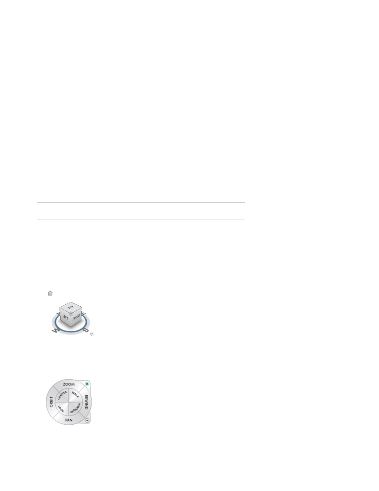
■ ViewCube. The ViewCube is an on-screen widget, shaped like a cube, that
rotates as you orbit your 3D scene and provides you with feedback about your
current camera viewing angle in relation to the model world. See “ViewCube”
on page 152.
■ SteeringWheels. SteeringWheels are task-based floating tool palettes that travel
with the cursor to minimize tool access time. SteeringWheels provide access
to different navigation tools grouped into various wheels depending on the
navigation task and user skill level. See “SteeringWheels” on page 133.
3
Page 16
■ Button menus. In Autodesk Navisworks, some toolbar buttons exist in mutually-exclusive groups of which only one at a
time can be selected. These buttons are now grouped under drop-down menus to improve accessibility and decrease screen
clutter.
■ Artificial horizon. You can now place your model against a fixed artificial horizon so that it appears more realistic and does
not float in mid air. The background of the 3D scene is split across the horizontal plane giving the effect of a sky and the
ground. The resulting artificial horizon gives you an indication of your orientation in the 3D world. See “Select Background
Effect” on page 170.
TimeLiner
Changes to the TimeLiner tool support improved integration with third-party planning tools, and make adding and editing
dates more intuitive.
■ Copy and paste TimeLiner dates.
■ Import and export support for the CSV file format.
■ Attach a selection to multiple TimeLiner tasks.
See “Overview of TimeLiner Tool” on page 335.
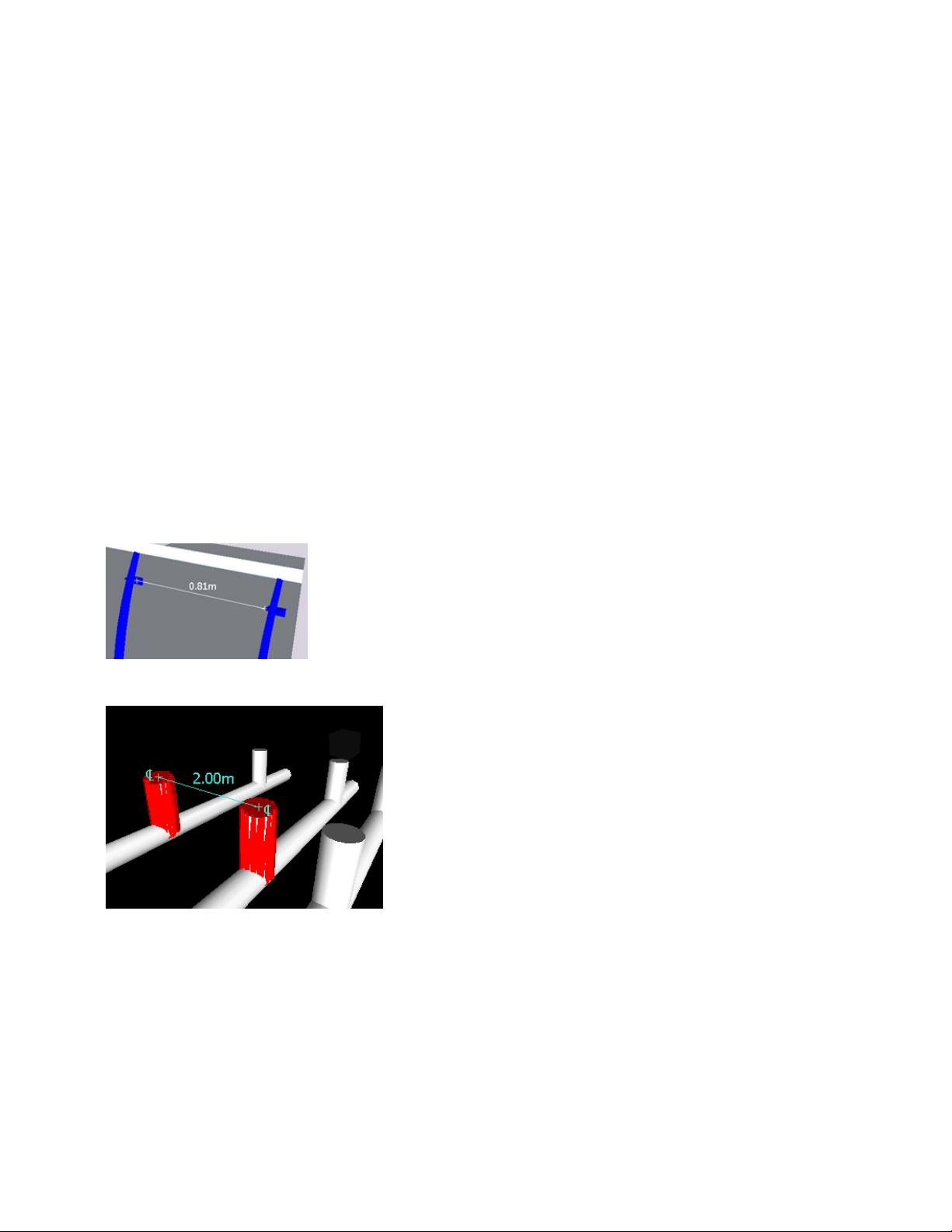
Measurement
Numerous improvements to the measurement tools allow greater accuracy when calculating dimensions and distances between
objects in your Autodesk Navisworks model.
■ Measure Shortest Distance. When measuring the distance between two objects, Autodesk Navisworks can now calculate
and display the shortest distance between the selected objects.
■ Measure distance between center lines of parametric objects.
■ When measuring distances you now have the option of converting measurements into redlines. The end markers, lines,
and dimension labels of your current measurement are converted into a redline and stored in the current viewpoint.
■ When measuring an angle, Autodesk Navisworks now displays a measurement arc.
4 | Chapter 1 What Is New in This Release?
Page 17

■ When measuring an area, Autodesk Navisworks now displays a dotted line to indicate the closure path for the area.
See “Measuring” on page 212.
Sectioning
Improved support for quick and accurate analysis of models using the sectioning toolset.
■ Create a user-defined section box to display only geometry within the defined section box.
■ Align section planes to specific faces of an object or line.
See “Sectioning” on page 244.
Clash Management
Managing multiple clashes has been enhanced, and contextual analysis of a clash relative to the model has been improved.
■ Group clash results into folders and subfolders to manage large numbers of clashes or related clashes.
■ Review clash results in the context of its surrounding geometry.
■ By modifying Clash Detective results display options (enable Dim Other and disable Hide Other), you can make surrounding
geometry transparent when reviewing clashes.
■ Smoothly zoom between clashes when reviewing multiple clashes.
■ A Reviewed status can be applied to a clash to indicate that a clash has been reviewed but not yet resolved.
■ Create a new clash rule to ignore clashes between objects that are connected, as identified by specific properties on each
item, or parent item
See “Overview of Clash Detective Tool” on page 371.
Auto-Save
You now have the option of automatically saving your work at regular intervals.
See “Automatically Save and Recover Files” on page 53.
Communication Center
The Communication Center allows the Autodesk Navisworks and Autodesk team to notify you of product-related updates
and announcements.
See “Use Communication Center” on page 7.
File Format Support
■ Support for JT file format, supporting most geometry types and object attributes. See “JTOpen File Reader” on page 100.
■ Support for CIMSteel Integration Standards (CIS/2). See “CIS2 File Reader” on page 93.
Miscellaneous Enhancements
■ Autodesk Navisworks Manage 2010 is available for full 64-bit installation.
| 5
Page 18

■ Manual override option allows you to specify the distance of Near and Far Clipping Planes. See “Use Culling” on page 174.
■ When entering invalid values in the Options Editor, you are notified of the error.
■ You can now configure site and project folders at install time, making deployment across an organization easier. See “Select
the Project and Site Folder Paths (optional)” on page 40.
■ Upgrades to the Autodesk Navisworks rendering engine (LADS) provide improved support for PNG transparencies and
improved rendering consistency.
■ Improved Revit support for: shared coordinates, rebars, True North, views, and viewpoints exported from Revit 9 and later.
6 | Chapter 1 What Is New in This Release?
Page 19

How to Get Assistance
There are various ways to find information about how to use this program, and
multiple resources are available.
Use Communication Center
Communication Center provides up-to-date product information,
software updates, product support announcements, and other
product-related announcements.
Overview of Communication Center
Communication Center provides up-to-date product information,
software updates, product support announcements, and other
product-related announcements.
Communication Center is an interactive feature that must be
connected to the Internet in order to deliver content and
information.
Each time Communication Center is connected, it sends your
information to Autodesk so that you receive the correct information.
All information is sent anonymously to Autodesk to maintain your
privacy.
2
The following information is sent to Autodesk:
■ Product name (in which you are using Communication Center)
■ Product release number
■ Product language
■ Country/region (specified in the Communication Center settings)
■ Your subscription contract number (if you’re a subscription
customer)
Autodesk compiles statistics using the information sent from
Communication Center to monitor how it is being used and how
it can be improved. Autodesk maintains information provided by
or collected from you in accordance with the company's published
privacy policy, which is available on http://www.autodesk.com/privacy.
Whenever new information is available, Communication Center
notifies you by displaying a balloon message below the
Communication Center button on the InfoCenter box.
7
Page 20

Communication Center provides the following kinds of announcements:
■ Product Support Information. Get breaking news from the Product Support team at Autodesk, including
when Live Update maintenance patches are released.
■ Subscription Announcements. Receive subscription announcements and subscription program news, as well
as links to e-Learning Lessons, if you are an Autodesk subscription member (available in countries/regions
where Autodesk subscriptions are offered).
For more information about Autodesk Subscription, see “Access Subscription Center” on page 13.
■ Articles and Tips. Be notified when new articles and tips are available on Autodesk websites.
■ Live Update Maintenance Patches. Receive automatic notifications whenever new maintenance patches are
released from Autodesk.
■ Featured Technologies and Content. Learn more about third-party developer applications and content.
You can customize the items that display on the Communication Center panel. For more information, see
“Specify Communication Center Settings” on page 8.
To open Communication Center
■ Click the Communication Center button on the Standard toolbar in the upper right-side of the application.
Menu: Help ➤ Communication Center
To receive new information notifications
■ Click the link in the balloon message below the notification icon on the Status bar.
To turn off Balloon Notifications
■ Right-click the notification icon on the Status bar, and click Disable Balloon Notifications.
Specify Communication Center Settings
You can specify Communication Center settings in the Options Editor.
In the Options Editor, you can specify the following settings:
■ General. Your current locations, how often to check for new online content, and maximum age of the
displayed articles.
■ Autodesk Channels. Channels to display in the Communication Center panel as well as the number of articles
to display for each channel.
■ Balloon Notification. Notifications for new product information, software updates, and product support
announcements. Also, you can customize the display time of the balloon.
To specify general settings for Communication Center
1 Open the Communication Center panel, and click Options.
2 In the Options Editor, expand the General node, and click the Communication Center option.
3 On the Communication Center page, select the country in which you are working. This is used for tailoring
location-specific Communication Center content.
4 Use the Check for New Online Content drop-down list to specify the desired frequency. By default,
Communication Center checks for new content every 4 hours.
5 To remove old content, select the Hide Old Content check box, and use the After box to set the number of
days after which old content is hidden. The default value is 14 days.
8 | Chapter 2 How to Get Assistance
Page 21

6 Click OK.
To specify the channels to display in the Communication Center panel
1 Open the Communication Center panel, and click Options.
2 In the Options Editor, expand the General node, expand the Communication Center node, and click the
Autodesk Channels option.
3 On the Autodesk Channels page, select the Subscribed check boxes for all channels you want to display.
4 Click OK.
To specify balloon notification settings
1 Open the Communication Center panel, and click Options.
2 In the Options Editor, expand the General node, expand the Communication Center node, and click the
Balloon Notifications option.
3 On the Balloon Notifications page, use the Enable Balloon Notifications check box to turn balloon notification
on/off.
4 In the Display Duration box, enter the number of seconds to set the length of time for balloon notifications
to display.
The default value for the balloon display time is 5 seconds.
5 Click OK.
Use the Help System
You can get much more benefit from the Help system when you learn how to use it efficiently.
The Help system contains complete information about using this program. In the Help window, you use the left
pane to locate information. The tabs above the left pane give you several ways for finding the topics you want
to view. The right pane displays the topics you select.
Find Information in Help
The tabs on the left side of the Help window provide different methods for finding information.
To locate a specific word or phrase in the current topic, click in the topic text and press the CTRL+F keys.
Contents Tab
■ Presents an overview of the available documentation in a list of topics and subtopics.
■ Allows you to browse by selecting and expanding topics.
■ Provides a structure so you can always see where you are in Help and quickly jump to other topics.
Index Tab
■ Displays an alphabetical list of keywords related to the topics listed on the Contents tab.
■ Accesses information quickly when you already know the name of a feature, command, or operation, or
when you know what action you want the program to perform.
Search Tab
■ Provides a keyword search of all the topics listed on the Contents tab.
■ Accepts the Boolean operators AND (+), OR, NOT (-), and NEAR.
■ Accepts the wild cards *, ?, and ~.
Use the Help System | 9
Page 22

■ Allows you to perform a search for a phrase when the phrase is enclosed in double quotes.
■ Displays a ranked list of topics that contain the word or words entered in the keyword field.
■ Arranges the results alphabetically by title or by location if you click on the Title and Location column
headings.
Use Searches
Use the Search tab to find relevant topics based on keywords that you enter.
The basic search rules are as follows:
■ Type your keywords in uppercase or lowercase characters; searches are not case-sensitive.
■ Search for any combination of letters (a-z) and numbers (0-9).
■ Do not use punctuation marks such as a period, colon, semicolon, comma, hyphen, and single quotation
marks; they are ignored during a search.
■ Group the elements of your search using double quotation marks or parentheses to set each element apart.
Use Wild Card Characters
You can use the following wild card characters in any keyword:
DescriptionSymbol
*
?
~
Replaces one or more characters when
used at the beginning, middle, or end of
a word. For example, “*lish”, “p*lish”, and
“pub*” will all find “publish”. Also, “anno*” will find “annotative”, “annotation”,
“annoupdate”, “annoreset”, and so on.
Replaces a single character. For example,
“cop?” will find “copy”, but not “copybase”.
Expands the tense of the word at the beginning or end of a word. For example,
“plotting~” will find “plots”, “plotted”,
and so on. Also, “~plot” will find “preplot”,
“replot”, and so on.
Search for Phrases
When searching for a phrase, use double quotation marks (" ") to enclose words that must appear next to each
other in the specified sequence. For example, enter "specifying units of measurement" to find only topics with
all those words in that order. If you don't use the quotation marks around that text, Help finds all topics containing
any one of the listed words, that is, all topics containing "specifying", all topics containing "units", all topics
containing "of", and all topics containing "measurement".
TIP If you can’t find the information you need through a search, try using the Contents tab.
Use Boolean Operators
With the AND, OR, NOT, and NEAR operators, you can precisely define your search by creating a relationship
between search terms. The following table shows how you can use each of these operators. If no operator is
10 | Chapter 2 How to Get Assistance
Page 23

specified, AND is used. For example, the query spacing border printing is equivalent to spacing AND border AND
printing.
ResultsExampleSearch for
"tree view" AND “palette”Both terms in the same
topic
viewpoint OR animationEither term in a topic
nwd NOT nwcThe first term without
the second term
user NEAR menuBoth terms in the same
topic, close together
NOTE The |, &, and ! characters do not work as Boolean operators. You must use AND (also +), OR, and NOT (also
-).
How Help Topics Are Organized
Most topics in this Help system have three tabs above the right pane of the Help window. The tabs display
different types of information.
■ Concept tab. Describes a feature or function. When you click the Concept tab, the Help Contents list in the
left pane of the Help window expands and highlights the current topic. The Contents tab displays the structure
of the Help on that topic. You can easily display nearby topics by clicking them in the list.
Topics containing both the
words "tree view" and "palette"
Topics containing either the
word "viewpoint" or the word
"animation" or both
Topics containing the word
"NWD," but not the word "NWC"
Topics containing the word
"user" within eight words of the
word "menu"
■ Procedure tab. Provides step-by-step instructions for common procedures related to the current topic. After
displaying a procedure, you can click the Procedure tab to redisplay the current list of procedures.
■ Quick Reference tab. Lists reference information related to the current topic.
When you click a different tab, the topic remains the same. Only the type of information displayed—concept,
procedures, or quick reference links—is different.
Concept Tab Organization
In a Concept tab, there are two types of information that may be displayed: navigation text and destination text.
Navigation text displays links with short descriptions. The purpose of navigation text is to guide you step-by-step
to the information that you need. The links on navigation pages lead to additional navigation pages deeper in
the Help structure until you come to a destination page. Each link is designed to provide you with more detailed
information.
Procedure Tab and Quick Reference Tab Organization
As you navigate deeper into the Help structure on the Contents tab, the corresponding information on the
Procedure tab and on the Quick Reference tab becomes more specific, and the number of entries displayed on
each of these two tabs decreases.
Print Help Topics
The quickest way to print the current topic is to right-click within the topic and click Print.
The Print button on the Help toolbar provides these print options:
■ Print the selected topic (recommended)
■ Print the selected heading and all subtopics
How Help Topics Are Organized | 11
Page 24
NOTE When you select the second option, you may get numerous printed pages, depending on how many subtopics
the currently selected topic contains.
To print a Help topic
1 Display the topic you want to print.
2 Right-click in the topic pane. Click Print.
3 In the Print dialog box, click Print.
To print a selected heading and all subtopics
1 Display the topic you want to print and make sure that the Contents tab is displayed.
2 On the Help toolbar, click Print.
3 In the Print Topics dialog box, click Print the Selected Heading and All Subtopics.
4 Click OK.
Show and Hide the Contents Pane
Use the Hide button on the Help toolbar to shrink the Help window to a compact size by hiding the pane that
contains the Contents, Index, and Search tabs.
The compact window size is best for displaying procedures while you work.
Use the Show button to expand the Help window to display the pane that contains Contents, Index, and Search
tabs. The expanded window size is best for locating and displaying conceptual and reference information.
Get More Help
You can access several additional sources of help.
■ On the Standard toolbar, use Communication Center. Display the Communication Center panel for product
updates and announcements.
■ Press F1. Displays context-sensitive reference information.
■ Click the Help button in many dialog boxes. Displays reference information for the dialog box.
■ View the product Readme. Displays late-breaking information about this product.
Other resources help you get information about Autodesk products and assistance with your questions about
this program.
■ Autodesk website. Access http://www.autodesk.com.
■ Local support. Check with your dealer or Autodesk country/region office.
Learn the Product
Training programs and products from Autodesk help you learn the key technical features and improve your
productivity. For the latest information about Autodesk training, visit http://www.autodesk.com/training or contact
your local Autodesk office.
12 | Chapter 2 How to Get Assistance
Page 25

Autodesk Authorized Training Centers
The Autodesk® Authorized Training Center (ATC®) network delivers Autodesk-authorized, instructor-led training
to design professionals who use Autodesk software. Autodesk Authorized Training Centers use experienced and
knowledgeable instructors. More than 1,200 ATC sites are available worldwide to meet your needs for
discipline-specific, locally based training.
To find a training center near you, contact your local Autodesk office or visit http://www.autodesk.com/atc.
Autodesk Official Training Courseware
Autodesk Official Training Courseware (AOTC) is technical training material developed by Autodesk. Designed
for traditional 1/2-day to 5-day, instructor-led classroom training and used by Authorized Training Centers and
other Autodesk partners, AOTC is well-suited for self-paced, stand-alone learning. The manuals cover key concepts
and software functionality with hands-on, step-by-step, real-world exercises. You can purchase AOTC from your
local reseller or distributor, or you can order it online from the Autodesk Store at http://www.autodesk.com/aotc.
e-Learning
Autodesk e-Learning for Autodesk Subscription customers features interactive lessons organized into product
catalogs. Each lesson is 20-40 minutes in length and features hands-on exercises, with an option to use a simulation
of the product or the actual application. You can also use an online evaluation tool that identifies gaps in skills,
determines what lessons will be most helpful, and gauges learning progress.
If you are a member of Autodesk subscription, you can access e-Learning and other subscription services from
within your Autodesk product.
For more information about how to access e-Learning in the product, see “Access Subscription Center” on page
13.
For more information about Autodesk subscription resources, visit http://www.autodesk.com/subscriptioncenter.
Autodesk Developer Network
The Autodesk Developer (ADN) program for ADN members provides support for full-time, professional developers
who want to build software based on Autodesk products. As an ADN member, you will receive the business,
software, support, and training you need to be successful. If you are a developer, visit http://www.autodesk.com/adn.
Autodesk Consulting
Autodesk Consulting provides services that help set up processes and provide critical training that will help
increase productivity so you can capitalize on the power of your products. For more information on general
consulting, systems integration, or custom training services, visit http://www.autodesk.com/consulting.
Partner Products and Services
Autodesk works together with thousands of software partners around the world. These partners provide products
and services that enhance Autodesk products for design professionals. Visit the Partner Products & Services page
at http://www.autodesk.com/partnerproducts for a list of resources available for your Autodesk product and your
industry.
Access Subscription Center
The Subscription Center is available to subscription members from within the product.
If you are a subscription member, you can access subscription services by clicking the Communication Center
button on the Standard toolbar, and then clicking a Subscription Center link. To learn more about Autodesk
subscription membership, visit http://www.autodesk.com/subscriptioncenter.
Access Subscription Center | 13
Page 26

About Subscription Center
With Autodesk Subscription, you get the latest releases of Autodesk software, incremental product enhancements,
personalized web support from Autodesk technical experts, and self paced e-Learning. Subscription services are
available to subscription members only.
By clicking the Communication Center button on the Standard toolbar, members have access to the following
options (under Subscription Center):
■ Subscription status. Checks your subscription status.
■ Create support request. Provides direct one-to-one communication with Autodesk support technicians. You
receive fast, complete answers to your installation, configuration, and troubleshooting questions.
■ View support requests. Tracks and manage your questions and responses through Autodesk's state-of-the-art
support system.
■ Edit Subscription Center profile. Sets up and maintains your subscription account.
■ View e-Learning catalog. Features interactive lessons organized into product catalogs.
■ e-Learning Lessons. (For subscription members only.) Each lesson is 15-30 minutes and features hands-on
exercises, with an option to use a simulation instead of the software application. You can use an online
evaluation tool that identifies gaps in skills, determines what lessons will be most helpful, and gauges learning
progress.
Subscription Resources and Privacy
Subscription resources provide interactive product features over the Internet. Each time you access subscription
resources (such as e-Learning or Create Support Request) from Communication Center in an Autodesk product,
product information (such as the serial number, version, language, and the subscription contract ID) is sent to
Autodesk for verification that your product is on subscription.
Autodesk compiles statistics using the information sent to subscription resources to monitor how they are being
used and how they can be improved. Autodesk maintains the information provided by or collected from you in
accordance with Autodesk's published privacy policy, which is available at http://www.autodesk.com/privacy.
To access the Subscription Center in the program
1 Click the Communication Center button on the Standard toolbar.
2 On the Communication Center panel, under Subscription Center, click the subscription resource you want
to access.
NOTE Subscription Center is not available to all product users. If subscription resources are not available in your
product, your product is not entitled to subscription benefits.
Manage Files with Autodesk Vault
If you are a subscription customer, you have access to Autodesk Vault, a file management tool that provides a
repository where documents and files are stored and managed.
Autodesk Vault gives you more power to manage files and track changes. Versioned copies of master files are
maintained, allowing you to easily revert to earlier versions of files. You can check files out for editing and later
check them back in. The master copy is never directly edited.
Autodesk Vault consists of two required components: the Autodesk Data Management Server and the Vault
Client. Optionally, you can also install the Vault Office Add-in.
For information about using the Vault, refer to the Vault Help system.
TIP The main components for the Autodesk Vault can be downloaded from the Autodesk Subscription site.
14 | Chapter 2 How to Get Assistance
Page 27

View the Product Readme
You can find late-breaking information about this software in the Readme.
It is suggested that you read through the Autodesk Navisworks Readme for information about recommended
hardware, updated installation instructions, and known software problems.
Join the Customer Involvement Program
You are invited to participate in helping guide the direction of Autodesk design software.
If you participate in the Customer Involvement Program (CIP), specific information about how you use AutoCAD
is forwarded to Autodesk. This information includes what features you use the most, problems that you encounter,
and other information helpful to the future direction of the product.
Here is a list of the information that is automatically sent to Autodesk:
■ Name and version of the Autodesk product
■ Number of minutes you are running the software
■ Number of sessions that end due to stability issues
■ Menu actions triggered
■ Error conditions encountered, fatal, and non-fatal
■ Import/export actions (including file extension used)
■ Scene statistics after a load or import (number of objects, faces, vertices etc.)
■ Operating system name and version
■ System configuration information such as processor, amount of memory, and graphics card
■ Other Autodesk products installed
■ Plug-in (DLLS) installed with Autodesk Navisworks
■ IP address, used to identify your country or region
What the Customer Involvement Program Cannot Do
The Customer Involvement Program is committed to protecting your privacy. It cannot do any of the following:
■ Collect any drawing or design data
■ Collect any identity information such as name, address, or phone number
■ Send you email or contact you in any other way
For additional information, click the links in the Customer Involvement Program dialog box.
Why You Should Consider Participating
The Customer Involvement Program involves you directly in telling Autodesk
■ The commands and features that Autodesk should focus on
■ The commands and features that are hardly ever used
■ The most common problem areas
■ The hardware typically used with Autodesk Navisworks
NOTE You can start or stop your participation in this program at any time. Access to the controls is available from the
Autodesk Navisworks Help menu. In network installations, your system administrator can choose whether to make the
CIP program available or not.
View the Product Readme | 15
Page 28

To turn the CIP on or off
1 Click Help ➤ Customer Involvement Program.
2 In the Customer Involvement Program dialog box, click a level of participation, and then click OK.
16 | Chapter 2 How to Get Assistance
Page 29

Installation
This chapter provides information about installing and activating Autodesk
Navisworks on a workstation, as well as deploying Autodesk Navisworks from a
network location.
Quick Start to Stand-Alone Installation
This section provides step-by-step instructions about how to prepare,
and then install Autodesk Navisworks.
If you have never installed the product before, you should familiarize
yourself with the entire installation process and options before
beginning.
For information about installing network-licensed or multi-seat
stand-alone versions of the program, see “Install Autodesk
Navisworks for Multiple Users” on page 28.
Prepare for Installation
To prepare for installation, you should review the system
requirements, understand administrative permission requirements,
locate your Autodesk Navisworks Manage 2010 serial number and
product key, and close all running applications.
3
Complete these tasks, and you are ready to begin installing Autodesk
Navisworks Manage 2010.
System Requirements for Stand-Alone Installation
The first task you need to complete is to make sure that your
computer meets the minimum system requirements. If your system
does not meet these requirements, problems can occur, both within
Autodesk Navisworks and at the operating system level.
Whether your Windows operating system is the 32-bit or the 64-bit
version, the version is automatically detected during installation.
NOTE Both the 32-bit version and 64-bit version of Autodesk Navisworks
Manage 2010 can be installed on a 64-bit version of Windows, but the
64-bit version of Autodesk Navisworks Manage 2010 cannot be installed
on a 32-bit version of Windows.
17
Page 30

See the following table for hardware and software requirements.
Hardware and software requirements
RequirementHardware/Software
32-BitOperating system
Windows© XP© Professional, SP 2 or SP 3;
Windows XP Home, SP 2 or SP 3; Windows
Vista Ultimate, SP 1; Windows Vista Enterprise, SP 1; Windows Vista Business, SP 1;
Windows Vista Home Premium, SP 1;
Windows Vista Home Basic, SP 1
64-Bit
Windows© XP© Professional, SP 1; Win-
dows Vista Enterprise, SP 1; Windows Vista
Business, SP 1; Windows Vista Ultimate, SP
1; Windows Vista Home Premium, SP 1
32-BitWeb browser
Microsoft© Internet Explorer 6.0, SP 1 or
later
Graphics card
64-Bit
Internet Explorer 7.0 or later
32-BitProcessor
AMD© Athlon©, 3.0 GHz or faster (minim-
um); Intel© Pentium© IV, 3.0 GHz or faster
(recommended)
64-Bit
AMD or Intel EM64T
32-BitRAM
512 MB (minimum) 2 GB or greater (recommended)
64-Bit
2 GB
128 MB, 1024 x 768 VGA, True Color
(minimum); 256 MB or greater - 1280 x
1024 32-bit color video display adapter,
True Color (recommended)
18 | Chapter 3 Installation
Installation 800 MBHard disk
MS-Mouse compliantPointing device
Any speed (for installation only)DVD-ROM
Page 31

Hardware and software requirements
Optional hardware
Open GL©-compatible 3D video card;
Printer or plotter; Modem or access to an
Internet connection; Network interface
card
Understand Administrative Permission Requirements
To install Autodesk Navisworks, you must have administrator permissions.
You do not need to have domain administrative permissions. See your system administrator for information
about administrative permissions.
To run Autodesk Navisworks, you do not need administrator permissions. You can run the program as a limited
user.
Locate Your Autodesk Navisworks Serial Number and Product Key
When you install Autodesk Navisworks, you are prompted for your serial number and product key in the Product
and User Information page.
The serial number must contain a three-digit prefix followed by an eight-digit number. The product key consists
of five digits.
The serial number and product key are located on the outside of the product packaging, or in the email you
received if you downloaded your product. Make sure to have these available before you install the program so
that you don't have to stop in the middle of the installation.
Make sure to have this number available before you activate the program so that you don't have to stop in the
middle of the installation.
The information you enter is permanently retained with the product. Because you can't change this information
later without uninstalling, take care when entering the information. To review this product information later,
click Help ➤ About.
NOTE If you have lost your serial number or product key, contact your local Autodesk office for assistance.
Avoid Data Loss During Installation
The Autodesk Navisworks installation process may stop if some applications (such as Microsoft® Outlook® or
virus-checking programs) are running.
Close all running applications to avoid possible data loss.
Choose a Language
You can select a different language for installation instructions, and a language for individual product installations
in the same install process.
When you start the installation process, the installer automatically determines your operating system language.
If a supported language is detected, your install pages are displayed in that language. If you want to change that
language, you select a different one from the Installer Language list on the first page of the Installation wizard.
Prepare for Installation | 19
Page 32

NOTE Some products may not have multi-language support at the time of product release. Additional language
support may be available later. Check http://autodesk.com/servicesandsupport for the availability of additional language
packs.
Using Language Packs
Language packs (.msi) support use of different languages in each Autodesk Navisworks product, including
exporters. Pack names start with NAVFREE_, NAVREV_, NAVSIM_, NAVMAN_, and exporters_ respectively.
NOTE You must install at least one language pack for each product.
It is possible to add additional language packs to Autodesk Navisworks products later. You can manually install
the required language packs by double-clicking on the language pack .msi file.
Language packs are located on the installation DVD and unpacked downloaded media under the x86 folder for
32-bit products and under the x64 folder for 64-bit products.
■ Language packs for specific products are included in the NAVFREE, NAVREV, NAVSIM, NAVMAN, and
NWEXPORT subfolders of x86 and x64 folders.
■ Language packs for specific languages are included in the en-US (English), de-DE (German), es-ES (Spanish),
fr-FR (French), it-IT (Italian), ja-JP (Japanese), ko-KR (Korean), pt-BR (Brazilian Portuguese), ru-RU (Russian)
and zh-CN (Chinese PRC) subfolders of the product folders.
So, for example, to install the 32-bit French language pack for Autodesk Navisworks Manage, double-click
x86/NAVMAN/fr-FR/NAVMAN_LP.msi.
Configure Button
During the installation process, you choose either a typical installation (install the product with default settings),
or a customized installation. If you choose to customize, you start that process in the Review - Configure - Install
dialog box. Select the appropriate product from the drop-down list, and click the Configure button.
After you click the Configure button, the following dialog boxes and options are displayed:
■ Select the License Type - Stand-Alone license or Network license. If you choose Network license, you also need
to select the license server model - Single, Distributed, or Redundant.
■ Project and Site Folders - These settings can be shared across an entire project site, or across a specific project
group depending on the required level of granularity. Refer to “Why should I specify the Project Folder and
Site Folder?” on page 46.
■ Select the Installation Type - Typical or Custom. If you choose a Typical installation (default settings), the
product installs the most common application features. To see which features are included in a Typical
installation, refer to “When performing a Typical installation, what gets installed?” on page 46. If you choose
Custom, you select specific features to install.
■ Include a Service Pack - If a service pack is available for your installation, you can include it.
When you have completed your choices, click the Configuration Complete button. This takes you back to the
Review - Configure - Create dialog box, where you can review your selections and complete the installation
process.
If you do not wish to make configuration changes on the Review - Configure - Install page, click Install.
Install Multiple or Bundled Products
Some Autodesk packages are comprised of multiple products or are part of multi-product bundles.
20 | Chapter 3 Installation
Page 33

The Installation wizard for packages that are comprised of multiple products gives you the option to choose
which products you want to install.
In the Installation wizard, for packages containing multiple products, you can choose which products and
languages you want to install. During the install process, you are informed whether a copy of the software is
already installed. You are also warned if your system does not meet the minimum system requirements for the
product. Each product name is displayed on its own tabbed panel; you can configure them individually.
If you purchased a package that is a multi-product bundle, such as an educational or institutional package, you
may have a package that includes several Autodesk products. For these bundled packages, an Installer disc contains
information for all the products in the package. The Installer disc helps you install all of the products.
Install and Run Autodesk Navisworks Manage 2010
To use the product, you must install the product, register and activate it, and then launch it.
You must have administrative permissions to install Autodesk Navisworks.
This section provides instructions for installing and activating Autodesk Navisworks for an individual user on a
stand-alone computer.
For information about installing network-licensed or multi-seat stand-alone versions of the program, see “Install
Autodesk Navisworks for Multiple Users” on page 28.
When you have successfully installed Autodesk Navisworks Manage 2010, you are ready to register your product
and start using the program. To register the product, start Autodesk Navisworks Manage 2010 and follow the
on-screen instructions. For more information, see “How do I register and activate Autodesk Navisworks?” on
page 47
NOTE Autodesk does not recommend or support the distribution of an Autodesk product using imaging software.
Install Autodesk Navisworks
The Autodesk Navisworks Installation wizard contains all installation-related material in one place.
From the Installation wizard, you can access user documentation, change the installer language, select a
language-specific product, install supplemental tools, view support solutions, and learn about deploying your
product on a network.
NOTE Autodesk Navisworks Manage 2010 ships on a single DVD. Insert the Autodesk Navisworks DVD in your DVD
drive to start the installation process. Follow the prompts to complete the installation. As long as the DVD is in the
drive, you can access documentation by clicking the documentation link.
■ Review installation documentation before you install. It is recommended that you take the time to familiarize
yourself with the complete installation process before you install Autodesk Navisworks. You can access PDF
versions of the licensing manuals and CHM versions of the installation manuals from the product's Installation
wizard by selecting the Read this Documentation selection, or the Documentation link at the bottom, left
pane of the install pages.
You can also access PDFs from the product disc. For late-breaking information, it is also recommended that
you review the product Readme.
NOTE To view or print PDF (.pdf) files, Adobe® Reader must be installed on your computer. If you do not have
Adobe Reader, you can download the latest version at http://www.adobe.com.
■ Install Autodesk Navisworks Manage 2010. From the Installation wizard, click Install Products. Follow the
on-screen instructions to complete the installation.
Install Autodesk Navisworks Using Default Values
This is the fastest means of installing Autodesk Navisworks on your system.
Install and Run Autodesk Navisworks Manage 2010 | 21
Page 34
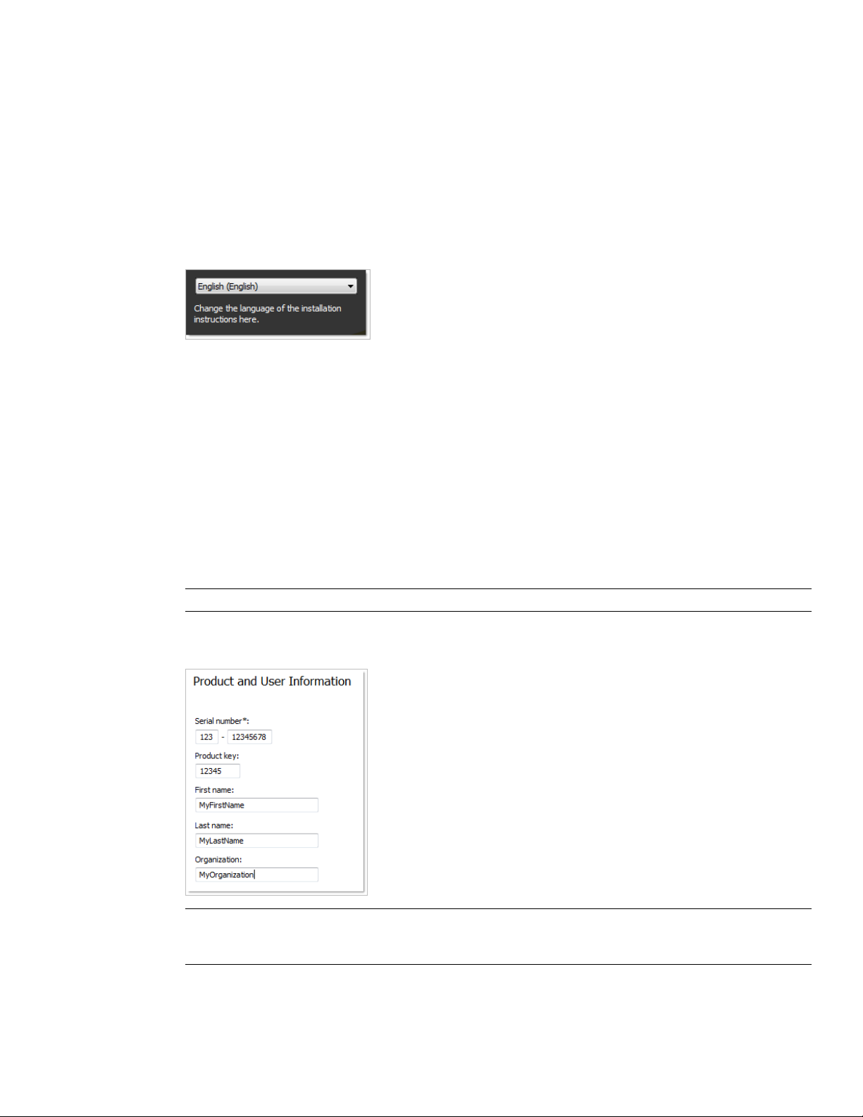
Only default values are used which means it is a typical installation being installed to C:\Program
Files\Autodesk\Navisworks Manage 2010.
To install Autodesk Navisworks using default values on a stand-alone computer
1 Insert the Autodesk Navisworks Manage 2010 DVD into your computer's DVD drive.
The Autodesk Navisworks Manage 2010 Installation wizard launches in the language that best matches the
settings on your computer.
If the Installation wizard does not start automatically, double-click Setup.exe at the root of the Autodesk
Navisworks DVD.
2 In the Installation wizard, select a language for the install instructions or accept the default language. Click
Install Products.
3 Select the products and the languages for the products you want to install:
■ On a 64-bit version of Windows, you can install both 32-bit and 64-bit versions of Autodesk Navisworks,
64-bit version of Autodesk Navisworks Freedom, and both 32-bit and 64-bit versions of exporter plugins.
■ On a 32-bit version of Windows, you can install 32-bit version of Autodesk Navisworks, 32-bit version
of Autodesk Navisworks Freedom, and 32-bit version of exporter plugins.
Click Next.
In order to choose a language for an individual product, you first must click the Select Language for Individual
Products check box, then select the language from the drop-down list. In some cases, additional languages
may not be available for the products you choose to install.
4 Review the Autodesk software license agreement for your country or region. You must accept this agreement
to proceed with the installation. Choose your country or region, click I Accept, and then click Next.
NOTE If you do not agree to the terms of the license and want to terminate the installation, click Cancel.
5 On the Product and User Information page, enter your serial number, product key, and user information.
Review the Privacy Policy from the link at the bottom of the dialog box. After reviewing, click Next.
IMPORTANT The information you enter here is permanent and is displayed in the Autodesk Navisworks Manage
2010 window (accessed by Help ➤ About) on your computer. Because you can't change this information later
without uninstalling the product, make sure you enter the correct information now.
6 On the Review - Configure - Install page, click Install to begin installing.
22 | Chapter 3 Installation
Page 35

The wizard does the following:
■ Uses a Typical installation, which installs the most common application features. To see which features
are included in a Typical installation, refer to “Typically Installed Features” on page 46.
■ Installs Autodesk Navisworks to the default install path of C:\Program Files\Autodesk\Navisworks
Manage 2010.
■ Installs the products you selected in Step 3.
NOTE By default, the Installation wizard automatically enables the exporter plugins for all 3rd party products
already installed on your PC.
7 On the Installation Complete page, choose from the following:
■ View the installation log file - to view the installation log file.
■ View the Autodesk Navisworks Manage 2010 Readme - to open the Readme file with the information
that was not available when the Autodesk Navisworks Manage 2010 documentation was prepared.
■ View the Autodesk Navisworks Freedom 2010 Readme - to open the Readme file with the information
that was not available when the Autodesk Navisworks Freedom 2010 documentation was prepared.
NOTE If you do not want to view the Readme files now, clear the check boxes.
8 Click Finish.
Install Autodesk Navisworks Using Configured Values
With this installation method, you can fine-tune exactly what gets installed by using the Configure option.
You can alter the installation type, the install path, the license type, and specify the location of the Project and
Site folders.
To install Autodesk Navisworks using configured values on a stand-alone computer
1 Insert the Autodesk Navisworks Manage 2010 DVD into your computer's DVD drive.
The Autodesk Navisworks Manage 2010 Installation wizard launches in the language that best matches the
settings on your computer.
If the Installation wizard does not start automatically, double-click Setup.exe at the root of the Autodesk
Navisworks DVD.
2 In the Installation wizard, select a language for the install instructions or accept the default language. Click
Install Products.
3 Select the products and the languages for the products you want to install:
■ On a 64-bit version of Windows, you can install both 32-bit and 64-bit versions of Autodesk Navisworks,
64-bit version of Autodesk Navisworks Freedom, and both 32-bit and 64-bit versions of exporter plugins.
■ On a 32-bit version of Windows, you can install 32-bit version of Autodesk Navisworks, 32-bit version
of Autodesk Navisworks Freedom, and 32-bit version of exporter plugins.
Click Next.
In order to choose a language for an individual product, you first must click the Select Language for Individual
Products check box, then select the language from the drop-down list. In some cases, additional languages
may not be available for the products you choose to install.
4 Review the Autodesk software license agreement for your country or region. You must accept this agreement
to proceed with the installation. Choose your country or region, click I Accept, and then click Next.
NOTE If you do not agree to the terms of the license and want to terminate the installation, click Cancel.
Install and Run Autodesk Navisworks Manage 2010 | 23
Page 36

5 On the Products and User Information page, enter your serial number, product key, and user information.
Review the Privacy Policy from the link at the bottom of the dialog box. After reviewing, click Next.
IMPORTANT The information you enter here is permanent and is displayed in the Autodesk Navisworks Manage
2010 window (accessed by Help ➤ About) on your computer. Because you can't change this information later
without uninstalling the product, make sure you enter the correct information now.
6 On the Review - Configure - Install page, click Configure to make configuration changes. Each of the products
you selected in Step 3 has its own tab:
■ For each of the selected products you can change the license type, installation type, installation path,
and the project and site folder paths.
■ For Navisworks exporter plugins, you can change which plugins are installed.
NOTE At any time you can click Next and then Configuration Complete to return to the Review-Configure-Install
page.
7 To configure a product installation:
a On the Select License Type page, you can choose to install a Stand-Alone License or Network license.
Click Next.
b On the Project and Site Folder Paths page, you can specify:
■ Project Folder - use the Browse button to select the directory that contains the product settings
specific to a project group.
■ Site Folder - use the Browse button to select the directory that contains the product settings standard
across the entire project site.
c On the Select the Installation Type page, you can choose to make the following configuration changes:
■ Typical - installs the most common application features.
■ Custom - installs only the application features that you select from the Select Features To Install
list:
Contains Navisworks ActiveX Lite control.ActiveX Lite Control
API
PDF Manual
Product
Sample RPCs
Contains the Component Object Model
interface for customizing and extending
the Navisworks functionality.
Contains various feature sample files.Example NWD files
Contains the Autodesk Navisworks User
Guide in PDF format.
Contains full set of Autodesk Navisworks
files.
Contains several Rich Photorealistic Content files.
■ Product Install Path - use the Browse button to select the drive and location where product will be
installed. Click Next.
8 To configure Navisworks exporter plugins, click the product tab. The Select the Installation Type page, shows
a list of all exporter plugins:
■ - indicates plugins with the 3rd party software already installed on your PC.
24 | Chapter 3 Installation
Page 37

■ - indicates plugins for the 3rd party software, which is either not installed on your PC or has not been
detected by the Installation wizard.
Select the check boxes next to all required plugins. If the 3rd party software has not been detected by the
wizard, you can manually enable the plugins for it. Selecting the check box automatically opens the dialog
box, which enables you to browse for the correct software installation directory.
9 Click another product tab to configure another product, or click Next and then Configuration Complete
to return to the Review-Configure-Install page. Then, click Install.
NOTE If you want a copy of your configuration summary information, click the Copy to Clipboard button.
10 On the Installation Complete page, choose from the following:
■ View the installation log file - to view the installation log file.
■ View the Autodesk Navisworks Manage 2010 Readme - to open the Readme file with the information
that was not available when the Autodesk Navisworks Manage 2010 documentation was prepared.
■ View the Autodesk Navisworks Freedom 2010 Readme - to open the Readme file with the information
that was not available when the Autodesk Navisworks Freedom 2010 documentation was prepared.
NOTE If you do not want to view the Readme files now, clear the check boxes.
11 Click Finish.
Launch Autodesk Navisworks
Assuming that you've followed all of the previous steps outlined in this Quick Start section, you can launch
Autodesk Navisworks and start taking advantage of its new and updated features.
You can start Autodesk Navisworks in the following ways:
■ Desktop shortcut icon. When you install Autodesk Navisworks, a shortcut icon is placed on your desktop.
Double-click the Autodesk Navisworks icon to start the program.
■ Start menu. On the Start menu, click All Programs (or Programs) ➤ Autodesk ➤ Navisworks Manage 2010 ➤
Autodesk Navisworks Manage 2010.
■ Location where Autodesk Navisworks is installed. If you have administrative permissions, you can run Autodesk
Navisworks in the location where you installed it. If you are a limited-rights user, you must run Autodesk
Navisworks from the Start menu or from the desktop shortcut icon. If you want to create a custom shortcut,
make sure that the Start In directory for the shortcut points to a directory where you have write permissions.
NOTE When the product is started, by default, it uses the language that best matches the settings on your computer.
You can also launch Autodesk Navisworks in another of the supported languages.
How to Launch Autodesk Navisworks in Another Language
To run Autodesk Navisworks in another of the installed languages, you need to add one of the language selector
arguments to the desktop shortcut.
To run Autodesk Navisworks in another language
1 Right-click the Autodesk Navisworks desktop shortcut, and click Properties on the shortcut menu to open
the Autodesk Navisworks Properties dialog box.
2 On the Shortcut tab, enter a space in the Target field after ..\roamer.exe, and then enter one of the following
arguments:
-lang en-US for English localization
-lang de-DE for German localization
Install and Run Autodesk Navisworks Manage 2010 | 25
Page 38

-lang es-ES for Spanish localization
-lang fr-FR for French localization
-lang it-IT for Italian localization
-lang ja-JP for Japanese localization
-lang ko-KR for Korean localization
-lang pt-BR for Brazilian Portuguese localization
-lang ru-RU for Russian localization
-lang zh-CN for Chinese (PRC) localization
3 Click OK to save the changes.
Add or Remove Features
You can add or remove Autodesk Navisworks Manage 2010 features at any time. For example, you may have
chosen a Custom installation option when you first installed Autodesk Navisworks, but now you want to add
features that you did not install originally. Or you may no longer need to use all of the features that were installed
originally.
You can add or remove features by using the Add or Remove Programs dialog box.
To add or remove features
1 In the Control Panel, double-click Add or Remove Programs.
2 In the Add or Remove Programs dialog box, click Autodesk Navisworks Manage 2010, and then click
Change/Remove in Windows XP or Uninstall/Change in Vista.
The Autodesk Navisworks Manage 2010 Installation wizard re-opens in Maintenance Mode.
3 Click Add or Remove Features. On the Add/Remove Features page, select a feature to install or uninstall.
The icons to the left of the selections give you an indication of the action that will be taken.
Indicates a feature that was marked for installation will be in a typical installation.
Indicates a feature that is not currently scheduled for installation.
Indicates a feature that was not originally marked for installation, but was added to the installed feature
list.
Indicates an installed feature that is chosen for removal.
NOTE If you need to revert to the Autodesk Navisworks Manage 2010 features that you selected in your original
installation, click Cancel.
Click Next.
4 On the Update Autodesk Navisworks Manage 2010 Installation page, click Next.
5 On the Update Complete page, you are informed when the updates have been performed. Click Finish.
Reinstall or Repair Autodesk Navisworks Manage 2010
If you accidentally delete or alter files that are required by Autodesk Navisworks Manage 2010, Autodesk Navisworks
might not perform correctly, and you might receive error messages when you try to execute a command or find
a file. You can attempt to fix this problem by reinstalling or repairing Autodesk Navisworks Manage 2010.
26 | Chapter 3 Installation
Page 39

The reinstallation or repair uses the features that were part of the installation type you chose when you initially
installed the program.
To reinstall or repair Autodesk Navisworks Manage 2010
1 In the Control Panel, double-click Add or Remove Programs.
2 In the Add or Remove Programs dialog box, click Autodesk Navisworks Manage 2010, and then click
Change/Remove in Windows XP or Uninstall/Change in Vista.
The Autodesk Navisworks Manage 2010 Installation wizard re-opens in Maintenance Mode.
3 Click Repair Autodesk Navisworks Manage 2010.
4 On the Select Repair or Reinstall page, click one of the following, and then click Next.
■ Repair My Autodesk Navisworks Manage 2010 Installation. This option replaces all registry entries that
Autodesk Navisworks initially installed and restores Autodesk Navisworks Manage 2010 to its default
state.
■ Reinstall My Autodesk Navisworks Manage 2010 Installation. This option repairs the registry and reinstalls
all files from the original installation. Use this option if the Repair My Autodesk Navisworks Manage
2010 Installation option does not solve the problem.
5 On the Repair Autodesk Navisworks Manage 2010 page, click Next to start the process.
6 On the Repair Complete page, you are informed when the repairs have been performed. Click Finish.
Uninstall Autodesk Autodesk Navisworks Manage 2010
When you uninstall Autodesk Navisworks Manage 2010, all components are removed. This means that even if
you've previously added or removed components, or if you've reinstalled or repaired Autodesk Navisworks Manage
2010, the uninstall removes all Autodesk Navisworks installation files from your system.
To uninstall Autodesk Navisworks Manage 2010
1 In the Control Panel, double-click Add or Remove Programs.
2 In the Add or Remove Programs dialog box, click Autodesk Navisworks Manage 2010, and then click
Change/Remove in Windows XP or Uninstall/Change in Vista.
The Autodesk Navisworks Manage 2010 Installation wizard re-opens in Maintenance Mode.
3 Click Uninstall.
4 On the Autodesk Navisworks Manage 2010 page, click Next to remove Autodesk Navisworks from the system.
5 When informed that the product has been successfully uninstalled, click Finish.
NOTE Even though Autodesk Navisworks Manage 2010 is removed from your system, the software license
remains. If you reinstall Autodesk Navisworks Manage 2010 at some future time, you will not have to register and
re-activate the program.
Move to Autodesk Navisworks from a Previous Release
If you have a previous version of Autodesk Navisworks installed on your system, you can install Autodesk
Navisworks Manage 2010 and keep other versions of the program on the same system. This is called a side-by-side
installation.
If you've purchased an upgrade version of Autodesk Navisworks Manage 2010, you are required to uninstall the
previous version within 120 days of installing Autodesk Navisworks Manage 2010. See your license agreement
for more information.
Move to Autodesk Navisworks from a Previous Release | 27
Page 40

Install Autodesk Navisworks for Multiple Users
This section provides step-by-step instructions for installing network-licensed or multi-seat stand-alone versions
of the Autodesk Navisworks Manage 2010.
Quick Start to Network Administration and Deployment
Network deployment of this program requires careful planning and execution.
If you are not familiar with network administration and deployment, you should familiarize yourself with the
following topics before you attempt to deploy and administer the program over a network.
Deployment Preparation
To prepare for a deployment, you should take the time to review the following requirements and options.
System Requirements for a Deployment
This section contains the system requirements for the location of the administrative image that you create, the
network license server, and the client workstation.
Before you begin installing the program on a network, make sure that your servers and client workstations meet
the minimum recommended hardware and software requirements for a deployment.
Whether the Windows operating system is the 32-bit or the 64-bit version is automatically detected when
installing Autodesk Navisworks. You can choose which versions of Navisworks will be installed.
NOTE Both the 32-bit version and 64-bit version of Autodesk Navisworks Manage 2010 can be installed on a 64-bit
version of Windows, but the 64-bit version of Autodesk Navisworks Manage 2010 cannot be installed on a 32-bit
version of Windows.
See the following tables for administrative image, license server, and client workstation system requirements.
Hardware and software requirements for the location of the administrative
image
RequirementHardware/Software
1.5 GB (recommended)Hard disk
Hardware and software requirements for the network license server
RequirementHardware/Software
Windows Vista 32-bitOperating system
Windows XP 32-bit
Windows 2003 Server Edition
Computer/processor
AMD® Athlon®, 3.0 GHz or faster (minim-
um)
Network interface card
28 | Chapter 3 Installation
Intel® Pentium® IV, 3.0 GHz or faster (re-
commended)
Compatible with existing Ethernet network
infrastructure
Page 41

Hardware and software requirements for the network license server
TCP/IPCommunication protocol
Hardware and software requirements for client machine
RequirementHardware/Software
32-BitOperating system
Windows©XP© Professional, SP 2 or SP 3;
Windows XP Home, and Professional, SP
2 or SP 3; Windows Vista Ultimate, SP 1;
Windows Vista Enterprise, SP 1; Windows
Vista Business SP 1; Windows Vista Home
Premium, SP 1; Windows Vista Home Basic,
SP 1
64-Bit
Windows Vista Enterprise, SP 1; Windows
Vista Business, SP 1; Windows Vista Ultimate, SP 1; Windows Vista Home Premium,
SP 1; Windows XP Professional, SP 1
32-BitWeb browser
Graphics card
Internet Explorer 6.0, SP 1 (or later)
64-Bit
Internet Explorer 7.0 or later
32-BitProcessor
AMD® Athlon®, 3.0 GHz or faster (minim-
um); Intel® Pentium® IV, 3.0 GHz or faster
(recommended)
64-Bit
AMD 64 or Intel EM64T
32-BitMemory (RAM)
512 MB (minimum); 2 GB or greater (recommended)
64-Bit
2 GB
128 MB, 1024 x 768 VGA, True Color
(minimum)
256 MB or greater - 1280 x 1024 32-bit
color video display adapter, True Color
(recommended)
Installation 800 MBHard disk
Quick Start to Network Administration and Deployment | 29
Page 42

Hardware and software requirements for client machine
MS-Mouse compliantPointing device
Any speed (for installation only)DVD-ROM
Open Open GL®-compatible 3D video cardOptional hardware
Printer or plotter
Modem or access to an Internet connection
Network interface card
Choose an Installation Type
When you set up your deployment, you need to choose the type of installation to deploy.
In the Autodesk Navisworks Manage 2010 Deployment wizard, you specify one of the following installation
types:
■ Network License installation. With this type of installation, you install the program to workstations with the
files and registry entries that allow the program to communicate with the Network License Manager. You
also define the configuration of the Network License Manager so that the licenses can be accessed. Workstations
running the program based on a network installation do not require individual activation. Licensing of this
program is managed by at least one license server.
The main advantage is that you can install Autodesk Navisworks Manage 2010 on more systems than the
number of licenses you have purchased (for example, purchasing 25 licenses but installing on 40 workstations).
At any one time, Autodesk Navisworks Manage 2010 runs on the maximum number of systems for which
you have licenses. This means you get a true floating license.
■ Multi-Seat Stand-Alone installation (Stand-Alone option). Choose this type of installation for stand-alone
installations where a single serial number and product key are used for multiple seats. Multi-seat stand-alone
installations do not rely upon a Network License Manager to manage product licenses; however, you can still
use the Autodesk Navisworks Manage 2010 Installation wizard to create administrative images and create
deployments. Registration and activation is more automated for multi-seat stand-alone installations. After
the first activation using the multi-seat stand-alone serial number, activation occurs automatically for all
workstations based on this deployment, as long as your systems are connected to the Internet.
■ Stand-Alone installation (Stand-Alone option). Choose this type of installation for stand-alone installations
where a single serial number and product key are used for a single seat. Like a multi-seat stand-alone
installation, you do not use the Network License Manager to manage product licensing, but installation,
registration, and activation occurs on each workstation.
If you choose one of the Stand-Alone installation types, you can proceed to the section “Distribute the Program”
on page 33.
Choose a License Server Model
If you chose the Network License option, you need to decide which license server model to use to distribute the
product licenses.
TIP If you are deploying a stand-alone or multi-seat stand-alone installation type, you do not use a license server model.
Proceed to the section “Distribute the Program” on page 33.
30 | Chapter 3 Installation
Page 43

For the network installation, use one of the following license server models:
■ Single license server model. The Network License Manager is installed on a single server, so license management
and activity is restricted to this server. A single license file represents the total number of licenses available
on the server.
■ Distributed license server model. Licenses are distributed across more than one server. A unique license file
is required for each server. To create a distributed license server, you must run the Network License Manager
on each server that is part of the distributed server pool.
■ Redundant license server model. You use three servers to authenticate a single license file. One server acts as
the master, while the other two provide backup if the master server fails. With this configuration, licenses
continue to be monitored and issued as long as at least two servers are still functional. The license file on all
three servers is the same. You must install the Network License Manager on each server.
Each of these license server models is described in detail in the Network Licensing Guide. It is strongly recommended
that you read that guide before you deploy the program. You can find the Network Licensing Guide by clicking
the Documentation link at the lower left corner of the Autodesk Navisworks Manage 2010 Deployment wizard.
Set Up Network Tools and Your License Server
If you are planning to have users run the program using network licenses, you need to use the Network License
Manager.
The Network License Manager helps you configure and manage license servers.
Install the Network License Manager
The Network License Manager is used to configure and manage the license servers.
To install your Network License Manager
1 In the Autodesk Navisworks Manage 2010 Installation wizard, click Install Tools and Utilities.
2 On the Select the Products to Install page, select Autodesk Network License Manager and click Next.
3 Review the Autodesk software license agreement for your country or region. You must accept this agreement
to proceed with the installation. Choose your country or region, click I Accept, and then click Next.
NOTE If you do not agree to the terms of the license and want to terminate the installation, click Cancel.
4 On the Review - Configure - Install page, review your product selection and the current settings. If you don't
want to make any changes, click Install. If you want to change the install type or installation path, click
Configure.
5 On the Select the Installation Type page, accept the default installation path (C:\Program Files\Autodesk
Network License Manager\) or Browse to specify a different path. If you enter a path that does not exist, a
new folder is created using the name and location you provide. Click Next.
WARNING Do not install the Network License Manager on a remote drive. When you install the Network License
Manager files, you must provide a path to a local drive. You must specify the drive letter; the universal naming
convention (UNC) is not supported.
6 On the Configuration Complete page, click Configuration Complete to return to the confirmation page.
7 On the Review - Configure - Install page, click Install.
8 When the Installation Complete page displays, click Finish.
Quick Start to Network Administration and Deployment | 31
Page 44

To Activate a Network License Through Autodesk.com
If your product does not include the Network License Activation Utility, you can activate your license by going
to https://registeronce.autodesk.com, and following the on-screen instructions.
Configure Your License Server
You configure a license server so that you can manage the Autodesk Navisworks product licenses.
You can configure the license server with the lmtools.exe utility.
You should be logged in with Administrator rights when working with the LMTOOLS utility.
To configure your license server
1 Do one of the following:
■ Click Start menu ➤ All Programs (or Programs) ➤ Autodesk ➤ Network License Manager ➤ LMTOOLS.
■ (Windows Vista) Double-click the LMTOOLS icon on the desktop.
2 In the Lmtools program, on the Service/License File tab, select the Configure Using Services option.
3 Click the Config Services tab.
4 In the Service Name list, select the service name you want to use to manage licenses.
By default, the service name is FLEXnet Service 1. If FLEXnet® is managing other software on your computer
in addition to Autodesk, you can change the service name to avoid confusion, for example, you can rename
FLEXnet Service 1 to Autodesk Server1.
NOTE If you have more than one software vendor using FLEXnet for license management, the Service Name list
contains more than one option. Make sure that only one Autodesk service is listed.
5 In the Path to Lmgrd.exe File field, enter the path to the Network License Manager daemon (lmgrd.exe), or
click Browse to locate the file.
By default, this daemon is installed in the C:\Program Files\Autodesk Network License Manager folder.
6 In the Path to the License File box, enter the path to your license file, or click Browse to locate the file.
7 In the Path to the Debug Log File box, enter a path to create a debug log, or click Browse to locate an existing
log file.
It is recommended that you save to the \Program Files\Autodesk Network License Manager folder. The log file
must have a .log file extension. For new log files, you must enter the .log extension manually.
8 To run lmgrd.exe as a service, select Use Services.
9 To automatically start lmgrd.exe when the system starts, select Start Server at Power Up.
10 Click Save Service to save the new configuration under the service name you selected in step 4. Click Yes
when prompted if you would like to save the settings to the service.
11 Click the Start/Stop/Reread tab and do one of the following:
■ If a service has not yet been defined for Autodesk, click Start Server to start the license server.
■ If a service for Autodesk is already defined and running, click ReRead License File to refresh the Network
License Manager with any changes made to the license file or Options file.
The license server starts running and is ready to respond to client requests.
12 Close lmtools.exe.
32 | Chapter 3 Installation
Page 45
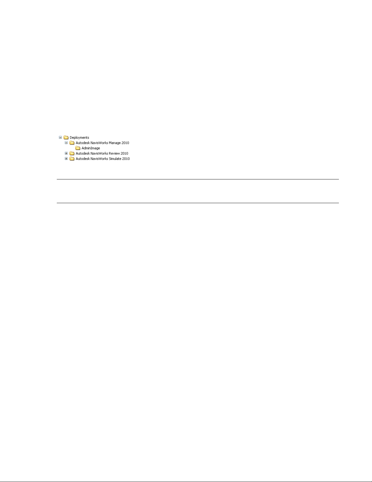
Distribute the Program
Once you have fully prepared for creating a deployment, you are ready to set up and distribute Autodesk
Navisworks by using the Deployment wizard and choosing a deployment method.
Create a Network Share
A network share is an installation folder that you make available to users' computers on a network. You point
users to this location to install the program. Create a network share that will be used by the Autodesk Navisworks
Deployment wizard during the creation of a client deployment.
A shared folder is required for network license and multi-seat stand-alone methods of installation.
It is recommended that you name the network share folder Deployments on the desktop of the system where you
want deployments stored. You can then add subfolders inside the shared Deployments folder that clearly convey
the name of product you plan to deploy. This is also beneficial if you plan to deploy multiple products.
Any subfolders that are placed inside a shared folder are automatically shared.
TIP You must have Full Control permissions set for your shared folder when you are creating your deployment images.
Read permissions are necessary to access the network share and administrative permissions on the workstation where
the program is deployed.
To create your network share
1 On the desktop of a network server, create a folder named Deployments.
2 Right-click the Deployments folder and click Share and Security (or Sharing).
3 In the [folder name] Properties dialog box, Sharing tab, select Share This Folder.
4 Specify a Share Name, such as Deployments, if necessary.
5 Click the Permissions button. In the Permissions dialog box make sure Full Control is active. Click OK.
In Vista, right-click the Deployments folder and then click Share. In the Properties dialog box select Sharing
and then Advanced Sharing to share the folder. Click the Permissions button to make sure Full Control is
active. Click OK.
These steps are important when creating your deployment images.
6 Click OK or Close to close the Properties dialog box.
7 For each product you plan to install, create a subfolder in the Deployments folder. Name each folder with
the pertinent product name.
Minimize the Chances of Installation Failure
The Navisworks installation process may stop if some applications, such as Microsoft Outlook or virus checking
programs, are running when you are creating a deployment. Close all running applications and temporarily
disable virus checking utilities.
Distribute an Autodesk Navisworks Product
You can choose from several methods of distributing an Autodesk program. Network sharing is the default
method.
■ Network Share. Users launch the program with the shortcut icon that you created with the Deployment
wizard. The program is installed on users' local computers, and a product icon appears on their desktop.
Quick Start to Network Administration and Deployment | 33
Page 46
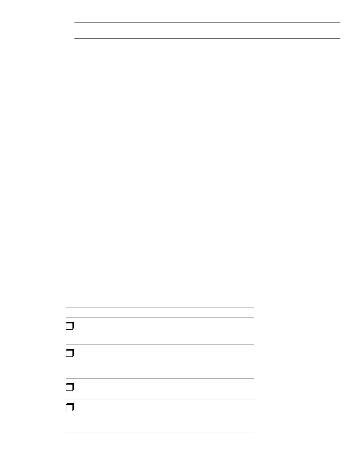
NOTE Users must have Read permissions to access the network share and administrative permissions on the
workstation where this program is installed.
■ Scripting. A script executes a command or a set of commands. Scripts are similar to batch files but are more
flexible. Installation scripts are most useful for stand-alone installation of programs on computers that are
connected to a network. Scripts are also useful for installing service packs, extensions, and object enablers
on a network.
■ Group Policy Objects (GPOs). With group policy objects, this program can be advertised to any Windows XP
or Windows Vista computer that is part of a Windows 2003 Server Active Directory environment.
Autodesk products are designed to be installed on a computer so that any user who logs on to the computer
can run the software. If you attempt to assign this program for a specific user rather than a computer, you
may encounter problems when a second specified user tries to install or uninstall a copy of the program.
■ Microsoft SystemCenter Configuration Manager (SCCM). You can deploy Autodesk software using Microsoft
System Center Configuration Manager (SCCM).
When you use SCCM to deploy Autodesk software, you set up the source directory using the Deployment
wizard. The Deployment wizard creates an administrative image that is used by SCCM to distribute the
Autodesk software to the target systems. The location where you perform the administrative installation
becomes the location of the package source directory.
■ Imaging Software. You can use imaging software, such as Norton Ghost, to create a master image to distribute
Autodesk products. Once created, the master image is then replicated to other computers throughout your
facility.
Care needs to be taken since the use of imaging software can result in conflicts with the product licensing,
incomplete installations, and problems with activation.
®
Set Up a Deployment
The deployment process provides you with numerous options for creating, and customizing your deployments,
so you should set aside ample time to complete the process in one sitting.
To be successful it is recommended that your review the following checklist and information before you begin.
The deployment process is initiated from the Deployment wizard. Once a deployment is created, users then
access the deployment to install products to their computers.
Preliminary Tasks for a Network Deployment
The deployment checklist gives you a quick summary of the type of information you should be familiar with
before begin. When you have completed these tasks, you are ready to create a deployment.
Deployment Checklist
You have reviewed the system requirements. You must
make sure that your network, servers, and client workstations meet the system requirements.
You understand the type of license you’ve purchased.
If you plan a network license deployment, you should
also be familiar with the type of license server model
you want to use and the license server names.
You have installed and activated any supporting tools
and utilities.
34 | Chapter 3 Installation
You have located your product serial number and
product key. The serial number and product key are
located on the outside of the product packaging, or in
the email you received if you downloaded your product.
Page 47

Deployment Checklist
You know how you’re going to personalize the programs during registration. Using consistent registration
data is very important.
You have identified the location (such as a shared folder)
where deployments will reside for each program you
plan to deploy.
You have closed all other programs and disabled antivirus software.
You have decided what languages you will include in
your administrative image, and what languages you will
use for your deployment package.
You have determined if your deployment plan involves
using imaging software to distribute your programs to
client workstations.
You have specified whether you want to create log files
that contain deployment and installation data, run silent
mode, and participate in the Customer Involvement
Program.
You know which type of installation you’ll perform typical or custom.
You have chosen the installation folder option.
You have decided if you want to include centralized
product settings with your deployment, such as global
options, workspaces, datatools, avatars, Clash Detective
rules, Presenter archives, custom Clash Detective tests,
object animation scripts, and so on.
You have set up access and participation in features like
the Customer Involvement Program.
Configure Button
During the deployment process, you can create a deployment that uses the default settings, or you can create a
customized deployment. To customize, you begin in the Review - Configure - Create Deployments dialog box.
Select the appropriate product from the drop-down list, and click the Configure button.
The following options are available after you click the Configure button. See “Your Deployment Choices” on
page 36 for more details about deployment options.
■ Select the License Type - Stand-alone or Network license
■ Select the Installation Type - Typical or Custom
■ Select the Project and Site Folder Paths
■ Select Installation Folder
When you finish selecting options for your customization, click the Configuration Complete button. The Review
- Configure - Create Deployments dialog box is displayed again, and you can review your selections. Once you
have confirmed your selections, click Create Deployment.
Set Up a Deployment | 35
Page 48
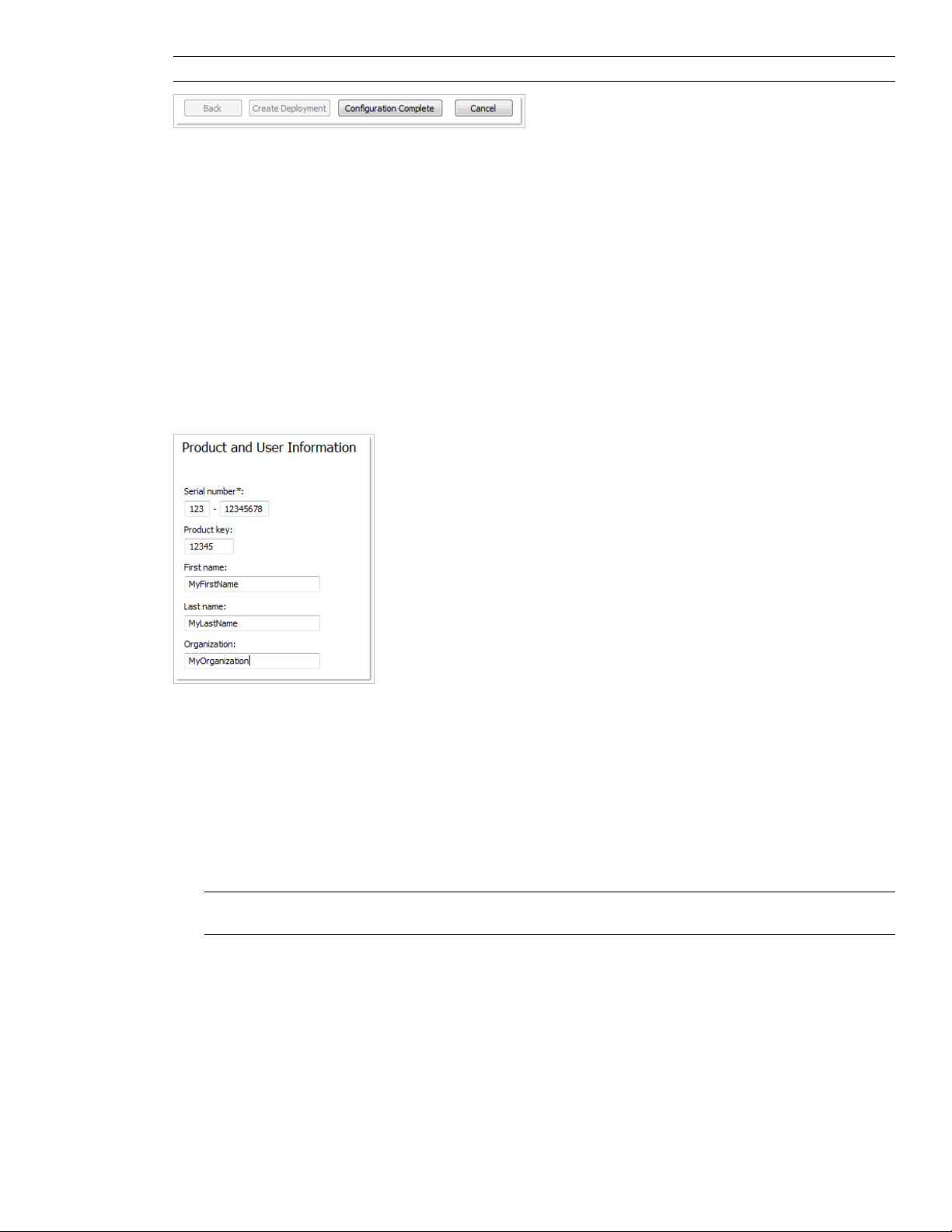
NOTE To get a copy of your settings, select the Copy to Clipboard button.
If you do not wish to make configuration changes on the Review - Configure - Create Deployments page, click
Create Deployment.
Your Deployment Choices
When you create a deployment, you will make several choices during the process to create various client
deployment images and deployment types. The following sections outline your choices in more detail.
Enter Product and User Information
The Product and User Information page is used to personalize the program for your environment.
The information you enter is permanently retained with the product and is displayed in the Help menu on all
workstations. Because you can't change this information later without uninstalling, take care when entering the
information.
You must also enter the product serial number and product key in order to run the product. The product serial
number and product key are located on the product packaging, or in the electronic fulfillment messaging. The
serial number must contain a three-digit prefix followed by an eight-digit number. The product key consists of
five digits.
Your client’s can review this product information later, by clicking Help ➤ About.
To enter your serial number and personal information
1 When creating a deployment, on the Product and User Information page, enter your product serial number
and the required personalization data.
NOTE Although it is required that you enter information in each box on this page, you can enter any information
that you want to convey to users who install the deployment.
2 Click Next.
Specify Log File Locations
The program has two types of log files with which you can monitor information about deployments and
installations.
■ Network log. The network log file keeps a record of all workstations that run the deployment. On the General
Deployment Settings page of the deployment process, you choose whether or not to create a network log
36 | Chapter 3 Installation
Page 49
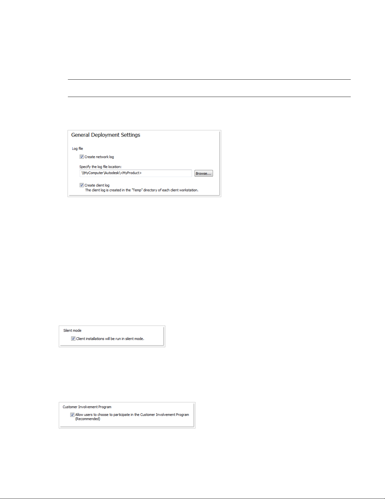
file. The log lists the user name, workstation name, and the status of the installation. Refer to this file for
status information and details about problems that users encountered during installation (for example, low
disc space or inadequate permissions).
The network log is named with the same name you chose for your deployment. You can specify where the
log file is created by entering either a valid UNC (universal naming convention) path or hard-coded path on
your network, for example \\MyComputer\Autodesk\<Autodesk product>. Users should use their actual computer
name in place of MyComputer.
NOTE The folder where the network log resides must be a shared folder where users who install the program have
Change permissions. Otherwise, successes or failures for user installations cannot be written to the log file.
■ Client log. The client log contains detailed installation information for each workstation. This information
may be useful in diagnosing installation problems. The client log is located in the %Temp% directory of each
client workstation.
To specify a log file location
1 While creating a deployment, on the General Deployment Settings page, select the check box next to the
Create Network Log box. Enter the name of the folder where you want the network log to be located.
2 If you want to create a client log, select the Create Client Log option.
3 Click Next.
What Is Silent Mode?
When silent mode is active and a user initiates the deployment, the installation proceeds without any explicit
user input.
No dialog boxes are presented that require interaction from the user. This includes all error and warning dialog
boxes. Check the log file for errors that may occur in the event of installation problems.
Customer Involvement Program (CIP)
If you choose to have your clients participate in the Customer Involvement Program, Autodesk Navisworks
Manage 2010 will automatically send Autodesk information about system configuration, what features you use
most, any problems that you encounter, and other information helpful to the future direction of the product.
Set Up a Deployment | 37
Page 50
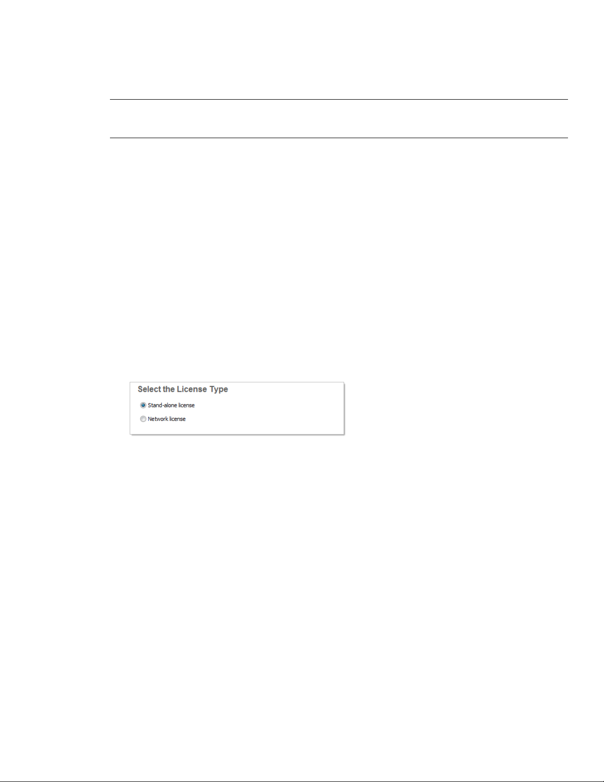
Select a License Type (optional)
When you set up your deployment, you choose the type of installation to deploy based on the type of software
license you purchased: stand-alone or network. You also select the network license server model you want to
use to distribute product licenses.
IMPORTANT Depending on the type of option you choose on the configuration page, network or stand-alone license,
note that you must use the same type of installation for all those products in your deployment session. If you select
products that do not support the type of license you purchased, you will not be able to activate those products.
Specify the license type to use during deployment
■ Stand-Alone license (a single serial number for a single seat). For a stand-alone license, you install, register,
and activate the program on each workstation.
■ Network license. With this type of installation, you install the program to workstations with the files and
registry entries that allow the program to communicate with the Network License Manager. You also define
the configuration of the Network License Manager so that the licenses can be accessed. Workstations running
the program based on a network installation do not require individual activation. Licensing of this program
is managed by at least one license server.
Specify the license server model during deployment
If you choose the Network license option, you need to decide which license server model to use to distribute
your product licenses - single, distributed or redundant license server model.
If you are deploying a stand-alone or multi-seat stand-alone installation type, you do not use a license server
model. For more information on server models, see “Choose a License Server Model” on page 30.
To deploy a stand-alone license
1 While creating a deployment, on the Select the License Type page, select Stand-alone license.
2 Click Next.
To deploy a network license using a single license server model
1 While creating a deployment, on the Select the License Type page, select the Network License option.
2 Select Single License Server as the license server model you want to use with the Network License Manager.
If you have already used the Network License Manager to create a license server model, you must select the
same license server model in this step. If you have not yet used the Network License Manager to create a
license server model, make sure that you select the same settings in the Network License Manager that you
choose here.
3 Enter the server name of the server that will run the Network License Manager, or click the Browse button
to locate the server. Click Next.
For more information about license server models and setting up your license server, see “Choose a License Server
Model” on page 30 or “Configure Your License Server” on page 32
To deploy a network license using a distributed license server model
1 While creating a deployment, on the Select the License Type page, select the Network License option.
2 Select Distributed License Server as the license server model you want to use with the Network License
Manager.
38 | Chapter 3 Installation
Page 51

If you have already used the Network License Manager to create a license server model, you must select the
same license server model in this step. If you have not yet used the Network License Manager to create a
license server model, make sure that you select the same settings in the Network License Manager that you
choose here.
3 Enter the name of one of the servers that will run the Network License Manager, or click the Browse button
to locate the server. Click Add to add the server to the Server Pool. Once all the servers are added to the
Server Pool list, use the Move Up and Move Down buttons to arrange the servers in the order you want
them to be searched by a user's workstation. You must enter at least two servers. Click Next.
For more information about license server models and setting up your license server, see “Choose a License Server
Model” on page 30 or “Configure Your License Server” on page 32
To deploy a network license using a redundant license server model
1 While creating a deployment, on the Select the License Type page, select the Network License option.
2 Select Redundant License Server as the license server model you want to use with the Network License
Manager.
If you have already used the Network License Manager to create a license server model, you must select the
same license server model in this step. If you have not yet used the Network License Manager to create a
license server model, make sure that you select the same settings in the Network License Manager that you
choose here.
3 In the First Server Name field, enter a server name of one server that will run the Network License Manager,
or click the Browse button to locate the server. Enter the server names for the remaining two servers that
you will use in the redundant server pool. Click Next.
NOTE If you are not sure how to obtain the server host name, see Plan Your License Server Configuration in the
Network Licensing Guide, located on the Documentation link of the Installation wizard.
For more information about license server models and setting up your license server, see “Choose a License Server
Model” on page 30 or “Configure Your License Server” on page 32
Select the Installation Type and Location (optional)
As part of making your deployment choices, you can select the type of installation that users receive when they
install the program, choose which optional features are included, and specify a product location.
■ Typical. Installs the most common application features. This option is recommended for most users.
■ Custom. Installs only the application features that you select.
To deploy a typical installation, and specify a product location
1 During the deployment, on the Select the Installation Type page, select Typical as the type of installation
that you want.
2 Enter the path on the client workstation where you want to install the program, for example C:\Program
Files\<Autodesk product>.
The Disc Space Requirements chart lets you review available drives and disc space.
3 Click Next.
To deploy a custom installation, choose optional features, and specify a product location
1 During the deployment, on the Select the Installation Type page, select the Custom option as the type of
installation that you want.
2 From the Select Features to Install list, select the features that you want to install.
Set Up a Deployment | 39
Page 52

Your choices are as follows:
Contains Navisworks ActiveX Lite control.ActiveX Lite Control
API
PDF Manual
Sample RPCs
Contains the Component Object Model
interface for customizing and extending
the Navisworks functionality.
Contains various feature sample files.Example NWD files
Contains the Autodesk Navisworks User
Guide in PDF format.
Contains full set of Navisworks files.Autodesk Navisworks Manage 2010
Contains several Rich Photorealistic Content files.
If, after making feature changes, you decide you want the original selections, click the Restore Defaults
button on the Select the Installation Type page.
3 Enter the path on the client workstation where you want to install the program, for example C:\Program
Files\<Autodesk product>.
The Disc Space Requirements chart lets you review available drives and disc space.
Select the Project and Site Folder Paths (optional)
When you set up your deployment, you can share various Autodesk Navisworks settings across entire project
site, or across a specific project group depending on the required level of granularity.
See also:
■ “How do I share the Autodesk Navisworks settings on a site and project basis?” on page 46
To select the Project and Site folder paths
1 On the Project and Site Folder Paths page, Project Folder box, click the Browse button to select the directory
that contains the Autodesk Navisworks settings specific to a project group.
2 In the Site Folder box, click the Browse button to select the directory that contains the Autodesk Navisworks
settings standard across the entire project site.
Choose a Language
You can select a different language for deployment instructions, and a language for product installations in the
same deployment process.
For example, if you need to provide Autodesk Navisworks to users in one or more languages different than your
own, you can download language packs from the installer that will allow you to deploy the product in the
languages you need to support.
NOTE Language packs can only be included in an administrative image during the creation of the deployment and
not during modification.
When you start the deployment process, the installer automatically determines your operating system language.
If a supported language is detected, your deployment pages are displayed in that language. If you want to change
that language, you can choose a different one from the installer language list on the opening page of the
Installation wizard.
40 | Chapter 3 Installation
Page 53

NOTE Some products may not have multi-language support at the time of product release. Additional language
support may be available later. Check http://autodesk.com/servicesandsupport for the availability of additional language
packs.
Using Language Packs
Language packs (.msi) support use of different languages in each Autodesk Navisworks product, including
exporters. Pack names start with NAVFREE_, NAVREV_, NAVSIM_, NAVMAN_, and exporters_ respectively.
NOTE You can only select one language pack for each product for deployment.
It is possible to manually add additional language packs to Autodesk Navisworks products later by double-clicking
on the language pack .msi file. Alternatively, you can set up and run scripts to install additional language packs.
Language packs are located on the installation DVD and unpacked downloaded media under the x86 folder for
32-bit products and under the x64 folder for 64-bit products.
■ Language packs for specific products are included in the NAVFREE, NAVREV, NAVSIM, NAVMAN, and
NWEXPORT subfolders of x86 and x64 folders.
■ Language packs for specific languages are included in the en-US (English), de-DE (German), es-ES (Spanish),
fr-FR (French), it-IT (Italian), ja-JP (Japanese), ko-KR (Korean), pt-BR (Brazilian Portuguese), ru-RU (Russian)
and zh-CN (Chinese PRC) subfolders of the product folders.
Create a Deployment
A deployment contains a Microsoft Transform (MST) file that modifies the default behavior of the installation
program.
As you begin a deployment, you need to select the location of your Administrative image, a deployment name,
and if your target systems are 32 or 64-bit operating systems.
Create a Deployment Using Default Values
This is the fastest means of creating client deployment images.
To create a default deployment
1 In the Deployment wizard, click Create Deployments.
2 On the Begin Deployment page, specify the following: administrative image location, deployment name,
and if your target system is 32 or 64-bit.
■ In the Administrative Image field, enter the path to your existing shared network location, or use the
Browse button to navigate to that location. This area is where you create and store your administrative
image. Users install the program from this location.
NOTE If you do not know how to create a network share, see “Create a Network Share” on page 33.
■ In the Deployment Name field, enter the new deployment's name. The name you enter here is the name
of the shortcut users will access to install the product.
■ Under This is to be a:, select either 32-bit or 64-bit for your target operating system. This selection does
not identify the system your deployment was created on; it identifies your target system.
Click Next.
Set Up a Deployment | 41
Page 54

3 On the Select the Products to Include in the Deployment page, select the products you want to include, the
languages to include in your administrative image, and the language of your deployment:
a For a 64-bit version of Windows, you can install both 32-bit and 64-bit versions of Autodesk Navisworks,
64-bit version of Autodesk Navisworks Freedom, and both 32-bit and 64-bit versions of exporter plugins.
b On a 32-bit version of Windows, you can install 32-bit version of Autodesk Navisworks, 32-bit version
of Autodesk Navisworks Freedom, and 32-bit version of exporter plugins.
After making your choices, click Next.
4 Review the Autodesk software license agreement for your country or region. You must accept this agreement
to proceed with the deployment. Choose your country or region, click I Accept, and then click Next.
NOTE If you do not agree to the terms of the license and want to terminate the installation, click Cancel.
5 On the Product and User Information page, enter your serial number, product key, and user information.
Review the Privacy Policy, and then click Next.
NOTE The information you enter here is permanent and is displayed in the Help menu on users’ computers.
Because you can't change this information later without uninstalling the product, make sure you enter the
information carefully.
6 On the General Deployment Settings page, choose whether or not you want to create network log and/or
a client log, if you want to run the client installation in silent mode, and if you want users to participate in
the Customer Involvement Program.
■ When you choose to create a network log file, you also have to specify where the log file is created by
entering either a valid UNC (universal naming convention) path or hard-coded path on your network.
The network log file is optional.
NOTE The folder where the network log resides must be a shared folder where users who install the program
have Change permissions. Otherwise, successes or failures for user installations cannot be written to the log
file.
■ Choose whether you want a client log file created.
■ If you want to prevent users from changing installation settings when they install, select Silent mode.
■ If you choose participation in the Customer Involvement Program, Autodesk sends helpful information
about the product.
For more information regarding log files, refer to “Specify Log File Locations” on page 36.
Click Next.
7 On the Review - Configure - Create Deployments page, click Create Deployment.
By clicking Create Deployment, an administrative image is created in your shared folder using the deployment
options listed in the Current Settings field. If you would like a summary of your deployment settings, click
the Copy to Clipboard button.
8 On the Deployment Complete page, click Finish.
Create a Deployment Using Configured or Customized Values
If you plan on altering your deployment by removing features or restricting access to online resources you can
create a configured or customized deployment.
To create a custom deployment
1 In the Deployment wizard, click Create Deployments.
42 | Chapter 3 Installation
Page 55

2 On the Begin Deployment page, specify the following: administrative image location, deployment name,
and if your target system is 32 or 64-bit.
■ In the Administrative Image field, enter the path to your existing shared network location, or use the
Browse button to navigate to that location. This area is where you create and store your administrative
image. Users install the program from this location.
NOTE If you do not know how to create a network share, see “Create a Network Share” on page 33.
■ In the Deployment Name field, enter the new deployment's name. The name you enter here is the name
of the shortcut users will access to install the product.
■ Under This is to be a:, select either 32-bit or 64-bit for your target operating system. This selection does
not identify the system your deployment was created on; it identifies your target system.
Click Next.
3 On the Select the Products to Include in the Deployment page, select the products you want to include, the
languages to include in your administrative image, and the language of your deployment:
a For a 64-bit version of Windows, you can install both 32-bit and 64-bit versions of Navisworks, 64-bit
version of Autodesk Navisworks Freedom, and both 32-bit and 64-bit versions of exporter plugins.
b On a 32-bit version of Windows, you can install 32-bit version of Navisworks, 32-bit version of Autodesk
Navisworks Freedom, and 32-bit version of exporter plugins.
After making your choices, click Next.
4 Review the Autodesk software license agreement for your country or region. You must accept this agreement
to proceed with the deployment. Choose your country or region, click I Accept, and then click Next.
NOTE If you do not agree to the terms of the license and want to terminate the installation, click Cancel.
5 On the Product and User Information page, enter your serial number, product key, and user information.
Review the Privacy Policy, and then click Next.
NOTE The information you enter here is permanent and is displayed in the Help menu on users’ computers.
Because you can't change this information later without uninstalling the product, make sure you enter the
information carefully.
6 On the General Deployment Settings page, choose whether or not you want to create network log and/or
a client log, if you want to run the client installation in silent mode, and if you want users to participate in
the Customer Involvement Program.
■ When you choose to create a network log file, you also have to specify where the log file is created by
entering either a valid UNC (universal naming convention) path or hard-coded path on your network.
The network log file is optional.
NOTE The folder where the network log resides must be a shared folder where users who install the program
have Change permissions. Otherwise, successes or failures for user installations cannot be written to the log
file.
■ Choose whether you want a client log file created.
■ If you want to prevent users from changing installation settings when they install, select Silent mode.
■ If you choose participation in the Customer Involvement Program, Autodesk sends helpful information
about the product.
For more information regarding log files, refer to “Specify Log File Locations” on page 36.
Click Next.
Set Up a Deployment | 43
Page 56

7 On the Review - Configure - Create Deployments page, click the Configure button to make changes to the
administrative image. Each of the products you selected to install, has its own configuration tab:
■ For Autodesk Navisworks Freedom 2010 you can change the installation path.
■ For Autodesk Navisworks Manage 2010, you can change the license type, installation type, installation
path, and the project and site folder paths.
■ For Navisworks exporter plugins, currently you cannot change which plugins are installed. By default,
the exporter plugins for all 3rd party products installed on a client PC will be automatically enabled.
Make your selections, and then click Next.
8 On the Configuration Complete page, select a different product tab to configure another product, or click
Configuration Complete to review your choices.
9 On the Review-Configure-Create Deployments page, click Create Deployment. If you want a summary of
your deployment settings, click the Copy to Clipboard button.
10 On the Deployment Complete page, click Finish.
Final Review and Complete Setup
To complete your deployment setup, confirm the settings you selected.
You have created an Autodesk product deployment with precise options that are specific to your group of users.
You can now use this deployment to install the program.
To confirm and complete the setup of a network deployment
1 On the Review - Configure - Create Deployments page, scroll the list of current settings and verify your
installation selections.
2 Click the Configure button, if you need to change any selections.
3 Click the Copy to Clipboard button, if you want a copy of the installation information.
4 Click Create Deployment.
5 On the Deployment Complete page, click Finish.
Modify a Deployment (optional)
After a deployment is created, it may be necessary to modify the deployment for some client workstations.
You can apply a patch or select various custom files that are not part of the base administrative image. You can
also perform modifications such as changing the installation directory from drive C to drive D.
To modify a deployment
1 Open the shared network folder where you originally chose to place your product deployment.
2 In the Tools folder, double-click the Create and Modify a Deployment shortcut.
This re-opens the Deployment wizard.
3 Click through the deployment pages and make the necessary changes.
4 After all the modifications have been made, click Create Deployment.
Point Users to the Administrative Image
When you have completed the deployment process, you are ready to have users install the newly created or
modified deployment.
44 | Chapter 3 Installation
Page 57

You need to notify your users of the shortcut that was created in the administrative image. The shortcut is the
same name that you chose when you created a deployment.
To point users to the administrative image
■ The simplest method of notifying users how to install the deployment is to email them with instructions
about using the shortcut. At a minimum, the instructions need to include the location of the deployment
and instructions about double-clicking the shortcut to the deployment.
Uninstall an Autodesk Product
When you uninstall an Autodesk product, all components are removed in the process.
This means that even if you have previously added or removed components, or if you have reinstalled or repaired
an Autodesk product, uninstalling removes all Autodesk product installation files from your system.
To uninstall the program
1 Do one of the following:
■ (Windows XP) Click Start menu ➤ Settings ➤ Control Panel ➤ Add or Remove Programs.
■ (Windows Vista) Click Start menu ➤ Control Panel ➤ Programs and Features ➤ Uninstall or change
a program.
2 In the Add/Remove Programs window, select Autodesk Navisworks Manage 2010, and then click
Change/Remove or Uninstall/Change.
3 Click Uninstall.
4 On the Uninstall Autodesk Navisworks Manage 2010 page, click Next to remove Autodesk Navisworks from
the system.
5 When informed that the product has been successfully uninstalled, click Finish.
NOTE Even though Autodesk Navisworks is removed from your system, the software license remains. If you reinstall
Autodesk Navisworks at some future time, you will not have to register and re-activate the program.
Installation Troubleshooting
This section provides solutions to installation issues and answers to commonly asked questions that may arise
while installing your products.
Additional troubleshooting information and support is also available at http://autodesk.com/support.
General Installation Issues
This section provides solutions to installation issues and answers to commonly asked questions that may arise
while installing your products.
How can I check my graphics card driver to see if it needs to be updated?
It is recommended that you verify and update your graphics card driver to optimize your program. Use the
following procedure to identify your current graphics card driver.
To identify your graphics card driver
1 Start Autodesk Navisworks Manage 2010.
2 Click Help ➤ System Info.
The Autodesk Navisworks Manage 2010 information dialog box opens.
Installation Troubleshooting | 45
Page 58
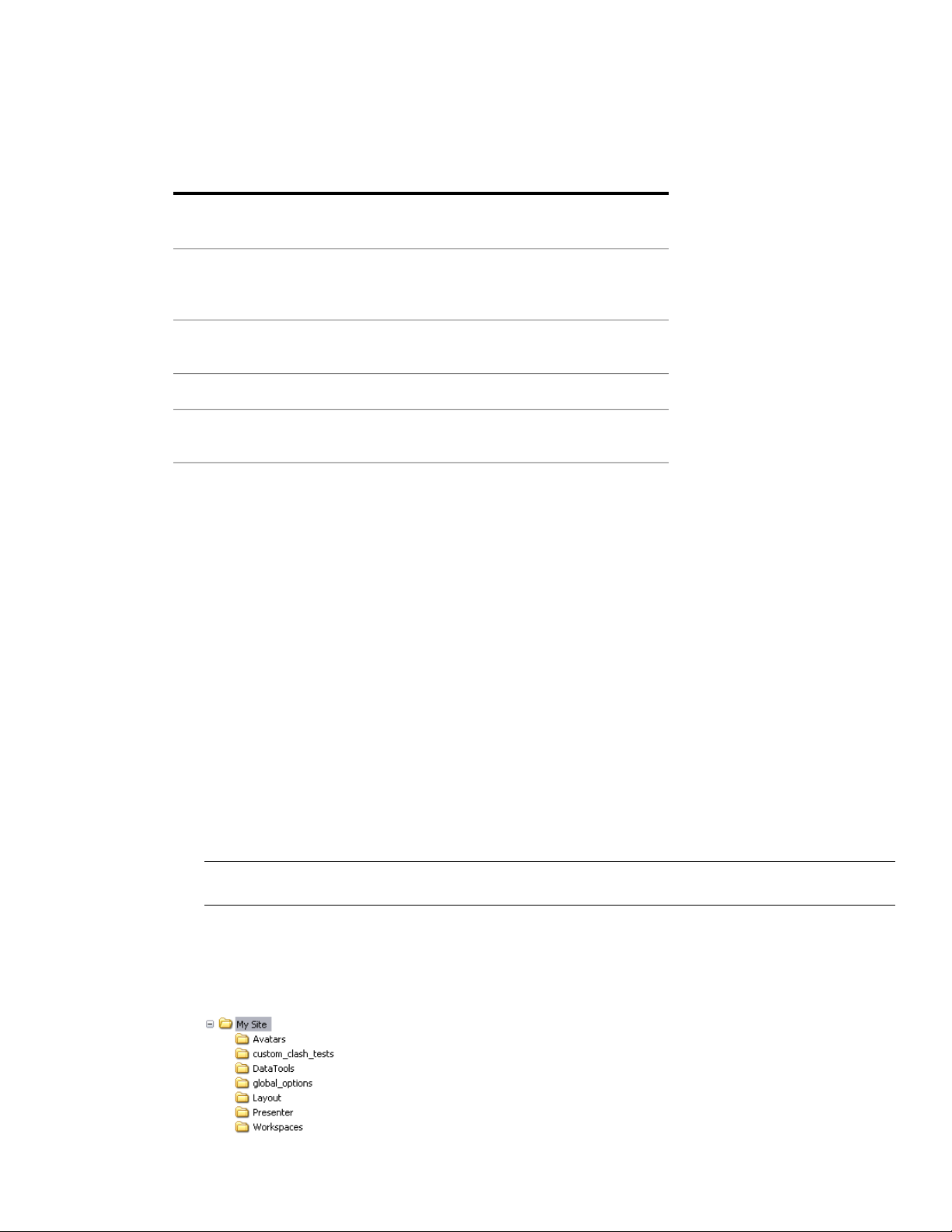
3 Review the information about your system including the graphics card driver and driver version, and click
OK to close the dialog.
When performing a Typical installation, what gets installed?
A Typical installation includes the following features:
Autodesk Navisworks Manage 2010
API
Sample RPC's
PDF manual
Contains full set of Autodesk Navisworks
Manage 2010 files
Contains the Component Object Model
interface for customizing and extending
the Autodesk Navisworks functionality
Contains several Rich Photorealistic Content files for the Presenter tool
Contains various feature sample filesExample NWD files
Contains the Autodesk Navisworks Manage
2010 user guide in PDF format
Why should I specify the Project Folder and Site Folder?
You can share global Autodesk Navisworks settings, workspaces, datatools, avatars, Clash Detective rules, Presenter
archives, custom Clash Detective tests, object animation scripts, and so on, with other users.
These settings can be shared across an entire project site, or across a specific project group depending on the
required level of granularity.
Autodesk Navisworks examines the current user profile and the all users profile on the local machine, and then
checks the settings in the Project Directory and the Site Directory. The files in the Project Directory take precedence.
How do I share the Autodesk Navisworks settings on a site and project basis?
To install Autodesk Navisworks with the pre-configured settings, such as a site-wide set of global options or
project-specific set of workspaces, you need to:
1 Configure and export required settings (such as workspaces, global options, clash tests and so on) in an
XML file format.
When you configure global options, you can lock some of the options to prevent users from editing them
later on local machines.
TIP If you want to create a locked global options file, run the stand-alone Options Editor from the command line
by typing “drive:pathname\OptionsEditor.exe” -l. The Options Editor opens with the locking facility.
2 Set up the Site and Project directory structure.
Typically, you need to place the Site and Project directories on a central server, so that they can be used for
centralized access by Autodesk Navisworks users.
The Site and Project Directories should contain the following subfolders:
46 | Chapter 3 Installation
Page 59

3 Place the exported settings inside the appropriate subfolders.
The centralized workspace files should go into the Workspaces subfolder, the centralized global options files
should go into the global_options subfolder, and so on.
Where are my product manuals?
All documentation created for Autodesk products are built in two different formats: PDF and CHM.
■ CHM files are made available during installation; click the Documentation link in the Installation wizard.
To access CHM files after the product is installed, use the Help system in the product.
■ PDF files are available after the product is installed; they are located in the Autodesk\Autodesk Navisworks
2010\<locale>\Manuals folder.
CHM files are installed to the \Autodesk\Autodesk Navisworks 2010\<locale> folder.
How do I register and activate Autodesk Navisworks?
The first time you start Autodesk Navisworks Manage 2010, the Product Activation wizard is displayed. You can
either activate Autodesk Navisworks at that time or run Autodesk Navisworks and activate it later.
Until you register and enter a valid activation code for Autodesk Navisworks Manage 2010, you are operating
the program in trial mode and the Product Activation wizard is displayed for 30 days from the first time that
you run the program. If after 30 days of running Autodesk Navisworks Manage 2010 in trial mode you have not
registered and provided a valid activation code, your only option is to register and activate Autodesk Navisworks
Manage 2010. You will not be able to run in trial mode after the 30 days expires. Once you register and activate
Autodesk Navisworks Manage 2010, the Product Activation wizard is no longer displayed.
TIP The fastest and most reliable way to register and activate your product is by using the Internet. Simply enter your
registration information and send it to Autodesk over the Internet. Once you submit your information, registration and
activation occur almost instantly.
To register and activate Autodesk Navisworks Manage 2010
1 Click Start menu ➤ All Programs (or Programs) ➤ Autodesk ➤ Autodesk Navisworks Manage 2010 ➤ Autodesk
Navisworks Manage 2010.
2 In the Autodesk Navisworks Manage 2010 Product Activation wizard, select Activate the Product, and then
click Next.
This starts the Register Today process.
3 Click Register and Activate (Get an Activation Code).
4 Click Next and follow the on-screen instructions.
If you do not have Internet access, or if you want to use another method of registration, you can register
and activate Autodesk Navisworks Manage 2010 in one of the following ways:
■ Email. Create an email message with your registration information and send it to Autodesk.
■ Fax or Post/Mail. Enter your registration information, and fax or mail the information to Autodesk.
General Installation Issues | 47
Page 60

Deployment Issues
This section outlines common issues and their solutions with regards to software deployments.
Is there a checklist I can refer to when performing a deployment?
The Installation chapter contains a complete section that describes preliminary actions and the entire deployment
process. See “Preliminary Tasks for a Network Deployment” on page 34.
Where should deployments be located?
Shared folders are required for both network license and multi-seat stand-alone methods of installation.
The shared folder (network share) is created before you run the Installation wizard and is where product
deployments are stored. It is recommended that you name the network share folder Deployments on the desktop
of the system where you want deployments stored. You can then add subfolders inside the shared Deployments
folder that clearly convey the names of products you plan to deploy. For example:
Any subfolders that are placed inside a shared folder are automatically shared.
NOTE You must have Full Control permissions set for your shared folder when you are creating your deployment
images. Read permissions are necessary to access the network share and administrative permissions on the workstation
where the program is deployed.
Where can I check if service packs are available for my software?
To find out if a patch or Service Pack is available for your product, visit the Autodesk Product Support page at
http://support.autodesk.com.
How do I choose between 32-bit and 64-bit deployments?
You have a choice of selecting 32-bit or 64-bit deployment. This choice controls which operating system the
deployment is targeted at, NOT what sort of products to include in the deployment.
■ Selecting 32-bit deployment gives you a choice of 32-bit products, and will only install on 32-bit operating
systems.
■ Selecting 64-bit deployment gives you a choice of 32-bit and 64-bit products, and will only install on 64-bit
operating systems.
So, for example, if you want to install 32-bit products on a 64-bit operating system, you need to choose 64-bit
deployment.
NOTE You can make either type of deployment from either type of operating system.
What are information channels?
The Communication Center allows you to receive announcements from various information channels. Through
information channels, you can receive the following:
■ Product Support information, including maintenance patch notifications.
48 | Chapter 3 Installation
Page 61

■ Subscription Center announcements and subscription program news, as well as links to e-Learning Lessons,
if you are an Autodesk subscription member.
■ Notifications of new articles and tips posted on Autodesk websites.
Licensing Issues
This section outlines common issues and their solutions with regards to software licenses and licensing your
products.
What is the difference between a stand-alone license and a network license?
Stand-alone licensed products are registered and activated to an individual workstation.
While the software can be installed on multiple systems in your facility, the license only allows one system to
be operational. The Portable License Utility can be used if a license needs to be transferred to another system. If
you need to run more systems, you need to purchase more stand-alone licensed products, or consider converting
to network licenses.
Network licensed products rely on the Network License Manager to keep track of software licenses.
The software can be installed and run on multiple systems, up to the maximum number of licenses you’ve
purchased. The Network License Manager "checks out" licenses until they are all in use. No further systems can
run the program until a license is "checked in." If you need to run more systems, you can purchase additional
licenses for the Network License Manager to maintain.
What is the benefit to using a network licensed version of the software?
Network licensed products are recommended for large drafting/design facilities, classrooms, and lab environments.
The main advantage is that you can install products on more systems than the number of licenses you have
purchased (for example, purchasing 25 licenses but installing on 40 workstations). At any one time, products
will run on the maximum number of systems for which you have licenses. This means you get a true floating
license. If software needs to be run on more systems, additional licenses can be purchased.
Registration and activation occurs only once and the licenses are maintained on your Network License Server.
What is Internet Explorer used for?
After installing your product, you can operate in trial mode for a given number of days. Whenever you launch
the program, you are prompted to activate the software.
When you choose to activate the software, Internet Explorer makes this process much faster.
Once you entered your registration data and submit it to Autodesk, an activation code is returned and you are
not prompted again during startup.
Networking Issues
This section outlines common issues and their solutions with regards to performing a network installation or
configuring your network license servers.
Where do I find my server name?
When installing a network licensed product, you must specify the name of the server that will run the Network
License Manager.
If you don’t know the server name, you can quickly find it by opening a Windows command prompt on the
system that will be the Network License Manager. At the prompt, enter ipconfig /all and note the Host Name
entry.
Licensing Issues | 49
Page 62

If I choose to create a log file, what kind of information does the log file contain?
There are two types of log files that can be generated that monitor information about deployments and
installations.
■ The Network log file keeps a record of all workstations that run the deployment. The log lists the user name,
workstation name, and the status of the installation. Refer to this file for status information and details about
problems that users may have encountered during installation.
■ The Client log file contains detailed installation information for each workstation. This information may be
useful in diagnosing installation problems. The client log is located in the \Temp directory of each client
workstation.
What is an administrative image (MSI) file?
An administrative image is a collection of shared file resources created during the deployment process and is used
by deployments to install the program to networked workstations. An.msi file is a Microsoft Installer file.
What is the impact of selecting all products to be included in the administrative image?
If you elect to include all products in your deployment, the administrative image will be larger.
You should select all products only when you create multiple deployments from this image and prefer not to
use the installation disk. If there are products you rarely or never use, and you do not expect to create additional
deployments, you should only select a subset of products.
You can still create a deployment at a later date, and include additional products, but you need to create a new
administrative image. You need the installation media to do so.
Uninstall and Maintenance Issues
This section outlines common issues and their solutions with regards to adding and removing features, reinstalling
or repairing your installation, and uninstalling products.
When adding or removing features, how can I tell what features get installed by default?
To quickly see what gets installed during a typical, default installation, click the Restore Defaults button on the
Add/Remove Features page.
Is it possible to change the installation folder when adding or removing features?
Once your product is installed, you cannot change the installation path from the Add/Remove Features page.
Changing the path while adding features results in program corruption, so it is not an option.
When should I reinstall the product instead of a repair?
You should reinstall your product if you accidentally delete or alter files that are required by the program. Missing
or altered files adversely affect the performance of your product and cause error messages when you try to execute
a command or find a file.
If an attempt to repair an installation fails, reinstalling is the next best option.
50 | Chapter 3 Installation
Page 63

Do I need my original disk to reinstall my software?
When performing a reinstall of the product, you do not need to have the original DVD on hand.
Installation data is cached locally on your drive and that data is reused when reinstalling.
When I uninstall my software, what files are left on my system?
If you uninstall the product, some files remain on your system such as files you created or edited.
Your license file also stays on your workstation when you uninstall your product. If you reinstall on the same
workstation, the license information remains valid and you do not have to reactivate the product.
Uninstall and Maintenance Issues | 51
Page 64

52 | Chapter 3 Installation
Page 65

Quick Start
This chapter helps you get up-to-speed with the Autodesk Navisworks interface.
Start and Quit Autodesk Navisworks
Once you've installed Autodesk Navisworks Manage 2010, you can
start it from the Windows desktop or from the command line.
To start Autodesk Navisworks, do one of the following from the
Windows desktop:
■ Double-click the Autodesk Navisworks icon, or
■ Go to Start ➤ All Programs (or Programs) ➤ Autodesk ➤
Navisworks Manage 2010 ➤ Autodesk Navisworks Manage 2010.
Autodesk Navisworks starts in the language that best matches the
settings on your computer. You can also start Autodesk Navisworks
in another of the installed languages.
NOTE You can add command line switches to specify different startup
routines for the program. See “Command Line Options” on page 55.
To quit Autodesk Navisworks, on the File menu, click Exit.
If the model has been changed since opening it, Autodesk
Navisworks asks you whether you want to save any changes. Respond
appropriately and Autodesk Navisworks will close.
4
Automatically Save and Recover Navisworks Files
Power cuts, system and software failures can cause Autodesk
Navisworks to close before you can save changes to your file.
Autodesk Navisworks can automatically save backup versions of a
file you are working on, enabling you to recover your work if
Autodesk Navisworks closes abnormally.
Auto-saved files have an .nwf format, and named as
<FileName>.AutoSave<x> where <FileName> is the name of the
current Navisworks file, and <x> is a number that increments with
each auto-save. So, for example, if you work with a file called
Enviro-Dome.nwd, the first auto-saved file is called
53
Page 66
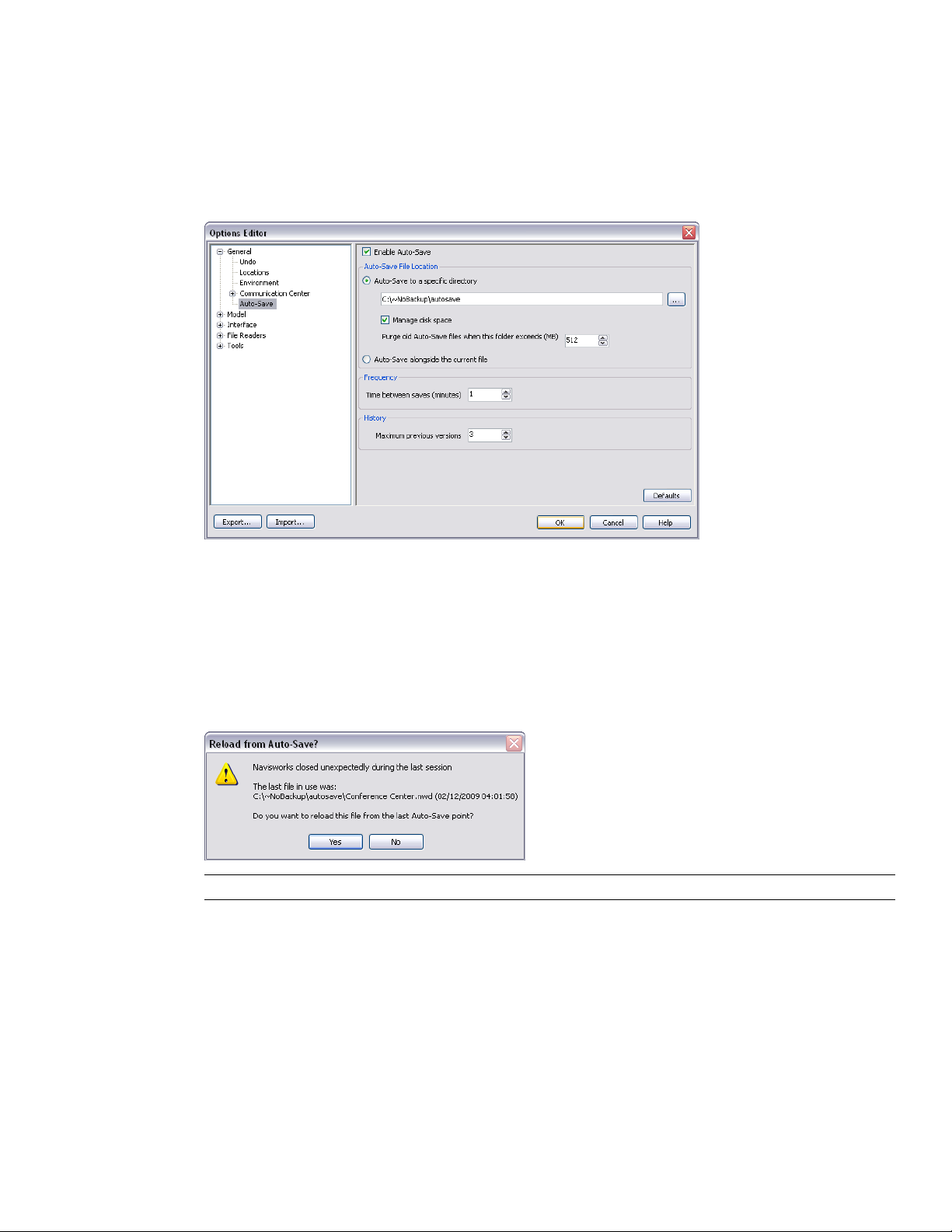
Enviro-Dome.Autosave0.nwf, the second auto-saved file is called Enviro-Dome.Autosave1.nwf and so on.
You can control a number of auto-save options, such as how often Navisworks saves your work, the location of
backup files, and the maximum number of backup files you want to keep.
To customize the auto-save options
1 Click Tools ➤ Global Options.
2 In the Options Editor, expand the General node, and click Auto-Save.
3 Adjust the auto-save options, as required. For example, if you want Navisworks to save a backup file every
20 minutes from a significant file change, enter 20 into the Time Between Saves (minutes) box.
4 Click OK.
To recover your work
1 Start Autodesk Navisworks. You are automatically prompted to reload the last file you were working on.
2 Click Yes to open the most recent saved version of the file.
NOTE Click No, if you don’t want to recover your work, or if you want to manually load a different backup file.
To manually load a backup file into Navisworks
1 Start Autodesk Navisworks. If you are prompted to reload the last file you were working on, click No.
2 Click File ➤ Open.
3 In the Open dialog box, browse to the folder that contains the backup files. By default, it’s <USERPROFILE>\
Application Data\<PRODUCTFOLDER>\AutoSave.
4 Click Open.
5 When you are prompted to save a file with a different name, click Save As.
54 | Chapter 4 Quick Start
Page 67
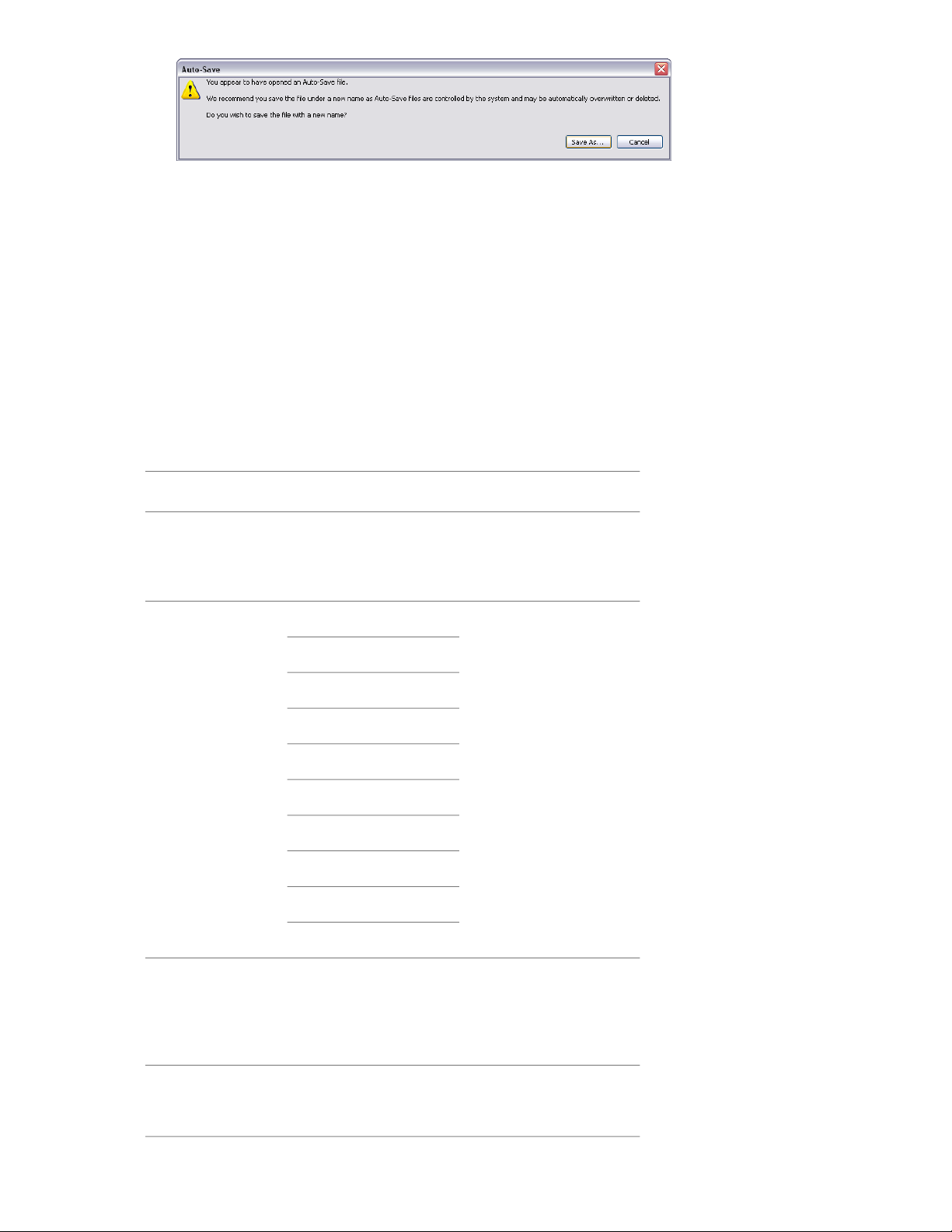
6 In the Save As dialog box, enter a new file name, and browse to the desired location.
7 Click Save.
Command Line Options
Command line switches can specify different startup routines for Navisworks.
You can use command line switches to specify several options when you start the program. For example, you
can run Autodesk Navisworks in another language, perform additional memory checks, load and append files,
output error reports. With command line switches, you can also set up several program icons, each with different
start-up options.
Command line switches are parameters you can add to the roamer.exe command line associated with a Microsoft
Windows® shortcut icon or the Windows Run dialog box. You can include several switches within a single
command line. Valid switches are listed in the following table.
®
Switch
[file_name.dmp]-dump
en-US = English-lang
de-DE = German
es-ES = Spanish
fr-FR = French
it-IT = Italian
ja-JP = Japanese
ko-KR = Korean
pt-BR = Brazilian Portuguese
ru-RU = Russian
DescriptionArgumentCommand Line
Outputs an error report to the
specified file. You must
provide the file name and file
path within quotation marks.
Launches Autodesk Navisworks in the specified language. It is possible to run
Autodesk Navisworks in a language other than the default
locale (for example, you can
run a Japanese version of
Autodesk Navisworks with
English default locale).
-memcheck
zh-CN = Chinese (PRC)
[filename.txt]-log
Outputs log to the specified
file. You must provide the full
file path within quotation
marks. For example,
“C:\temp\log.txt"
Runs Autodesk Navisworks
with additional checks for
memory errors.
Command Line Options | 55
Page 68

Switch
DescriptionArgumentCommand Line
[outputfile.nwc] [inputfile]-nwc
[outputfile.nwd] [input file]-nwd
[filename.xml]-options
Autodesk Navisworks converts
an input file into the NWC
format in the background, and
places it into the specified directory. You must provide the
full file paths within quotation
marks. For example,
“C:\temp\a.dwg"
Autodesk Navisworks converts
an input file into the NWD
format in the background, and
places it into the specified directory. You must provide the
full file paths within quotation
marks. For example,
“C:\temp\b.dwg"
Starts Autodesk Navisworks,
and imports the global options from the specified global
options file. You must provide
the full file path within quotation marks. For example,
"C:\temp\my_global_options.xml"
-regserver
Registers roamer.exe with
COM.
The syntax for using command line switches is:
“drive:pathname\roamer.exe” [switches] [“file1”] [“file2”] [“fileN”], where [switches] are the valid
command line switches in any order, and [file1]...[fileN] are the files to be loaded and appended together, if
required. You must provide the full file paths within quotation marks.
For example, the following entry starts the program from a folder named Autodesk Navisworks in Russian language,
loads the global options file options.xml, and creates a log file log.txt.
"C:\Autodesk Navisworks\roamer.exe" -options "C:\temp\options.xml" -lang ru-ru -log
"C:\temp\file.log"
To start the program with a command line switch
1 Right-click the program icon on the Windows desktop. Click Properties.
2 In the Autodesk Navisworks Properties dialog box, Shortcut tab, in the Target box, edit the parameters for
the switch using the following syntax:
“drive:pathname\roamer.exe” [switches] [“file”] [“file2”] [“fileN”], where [switches] are the valid
command line switches in any order, and [file1]...[fileN] are the files to be loaded and appended together,
if required. You must provide the full file paths within quotation marks.
For example, enter: “D:\Autodesk Navisworks\roamer.exe" -log "D:\temp\nw_log.txt" "D:\temp\a.nwd"
"D:\temp\b.dwg".
3 Click OK.
56 | Chapter 4 Quick Start
Page 69
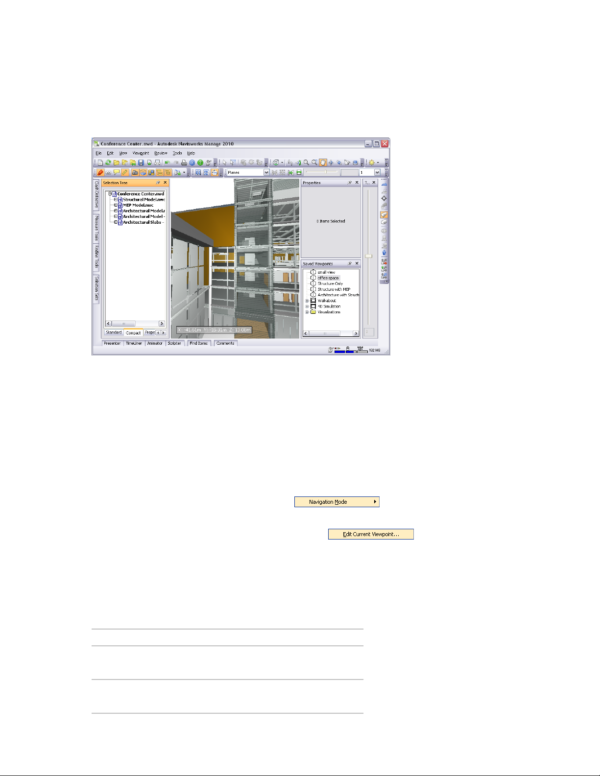
The User Interface
The Autodesk Navisworks interface contains a number of traditional Windows elements, such as toolbars, dockable
windows, dialog boxes and shortcut menus in which you complete tasks.
Parts of Autodesk Navisworks Interface
This section briefly describes the main interface components.
The Autodesk Navisworks interface is intuitive and easy to learn and use. You can adjust the application interface
to match the way you work. For example, you can hide toolbars that you rarely use, so they do not clutter the
interface. You can add and remove buttons from toolbars. You can also create your own toolbars.
Menu Bar
The Menu bar contains all commands available in Autodesk Navisworks, grouped together by similar or 'like'
functionality.
For example, all commands related to review functionality are located under the Review menu, all commands
related to user assistance are located under the Help menu and so on.
When a menu has a right-pointing arrow, such as , there is a submenu associated with that
choice.
When a menu item is followed by a series of dots, such as , there is a dialog box associated
with that choice.
Quick Reference
File Menu
This menu contains commands for managing files.
DescriptionOption
New
Refresh
Resets the program, and closes the currently open Navisworks file.
Refreshes your scene with the latest versions of currently loaded model files.
The User Interface | 57
Page 70

DescriptionOption
Displays the Open dialog box.Open
Displays the Open URL dialog box.Open URL
Displays the Append dialog box.Append
Displays the Merge dialog box.Merge
Saves the currently open Navisworks file.Save
Displays the Save As dialog box.Save As
Displays the Publish dialog box.Publish
Displays the Print dialog box.Print
Enables print preview mode.Print Preview
Displays the Print Setup dialog box.Print Setup
Delete
Send
Import
Export
Recent Files
Deletes the selected files. You can only
delete appended files.
Saves the currently open Navisworks file,
accesses your email program, and adds the
saved file as an email attachment.
Displays the Import dialog box, and enables you to import Intergraph PDS review
data, and various Navisworks data.
Displays the Export dialog box, and enables you to export data from Navisworks.
Displays shortcuts to the most recently
opened files.
Exits the program.Exit
Edit Menu
This menu contains commands for locating, selecting and editing geometry in your model.
DescriptionOption
Reverses the last performed operation.Undo
Redo
Quick Find Next
58 | Chapter 4 Quick Start
Reverses the last operation performed by
the Undo command.
Gives you access to selection functionality.Select
Displays the Quick Find dialog box.Quick Find
Repeats the previously run quick find
search.
Toggles the Find Items control bar.Find Items
Page 71

DescriptionOption
Toggles the Find Comments dialog box.Find Comments
Toggles hidden mode for selected items.Hidden
Toggles required mode for selected items.Required
Toggles hidden mode for unselected items.Unselected Hidden
Override Item
Reset Item
Reset All
Sort
File Units an Transform
Enables you to override color, transparency, and transform for selected items.
Enables you to reset selected items back
to their original state.
Enables you to reset all overridden items
back to their original state.
Enables you to sort the items in the Selection Tree alphabetically.
Displays the File Units and Transform dialog box.
View Menu
This menu contains commands that control the Navisworks interface.
DescriptionOption
Control Bars
Enables you to toggle the display of control
bars.
Enables you to control workspaces.Workspaces
Scene View
Head-Up Display
Enable you to control the views in the
Scene Area.
Enables you to control the Head-Up Display
elements.
Enables you to control the SteeringWheels.SteeringWheels
Puts the video output into stereo mode.Stereo
Displays the Stereo Options dialog box.Stereo Options
Displays useful scene statistics.Scene Statistics
Viewpoint Menu
This menu contains a set of commands that affect the current viewpoint, including model appearance, navigation
and sectioning.
DescriptionOption
Enables you to use saved viewpoints.Saved Viewpoints
Look From
Enables you to look from a preset viewpoint.
Parts of Autodesk Navisworks Interface | 59
Page 72

DescriptionOption
Set Viewpoint Up
Navigation Tools
Sectioning
Edit Current Viewpoint
Sets the viewpoint up vector to align with
the selected orientation.
Enables you to select rendering mode.Rendering
Enables you to select lighting mode.Lighting
Enables you to display primitives.Display
Enables you to select navigation mode.Navigation Mode
Enables you to control the camera during
interactive navigation.
Enables you to create a limited volume of
your model.
Displays the Edit Viewpoint dialog box for
the current viewpoint.
Review Menu
This menu contains commands for reviewing and markup.
DescriptionOption
Comments
Redline
SwitchBack
Renumber Comment IDs
Renumber Tag IDs
Enables you to add and manage comments.
Enables you to add and manage annotations.
Enables you to use the measure tools.Measure
Enables you to add and manage hyperlinks.Hyperlinks
Enables you to locate review tags.Tags
Sends the current view of the currently
loaded file back to AutoCAD or MicroStation-based program.
Renumbers all comment IDs, making them
unique to the scene.
Renumbers all tag IDs, making them
unique to the scene.
Tools Menu
This menu contains commands for advanced model analysis and reviewing, and also commands for customizing
Autodesk Navisworks.
60 | Chapter 4 Quick Start
DescriptionOption
Toggles the Clash Detective tool window.Clash Detective
Toggles the Presenter tool window.Presenter
Toggles the TimeLiner tool window.TimeLiner
Page 73

DescriptionOption
Displays the DataTools dialog box.DataTools
Toggles the Animator tool window.Animator
Toggles the Scripter tool window.Scripter
Displays the Compare dialog box.Compare
Toggles the Redline Tools tool window.Redline
Toggles the display of hyperlinks.Hyperlinks
Toggles the display of smart tags.Smart Tags
Toggles the Measure Tools tool window.Measure
Animation
Background
Enables you to control animation playback,
and record viewpoint animations.
Enables you to select a background color
for the Scene Area.
Displays the File Options dialog box.File Options
Displays the Customize dialog box.Customize
Displays the Options Editor.Global Options
Help Menu
This menu provides access to the Autodesk Navisworks online reference system.
DescriptionOption
Opens the Help system.Help Topics
Communication Center
Navisworks on the Web
Opens the Communication Center
dockable window.
Opens the context-sensitive help.What’s This
Displays the Autodesk Navisworks
product page.
Customer Involvement Program
System Info
About Autodesk Navisworks
Manage 2010
Displays the Customer Involvement dialog box.
Displays detailed information about your
system.
Displays copyright and license information about your copy of Autodesk Navisworks, and enables you to access the
Product Information dialog box.
Toolbars
Autodesk Navisworks toolbars provide quick access to frequently used commands.
Parts of Autodesk Navisworks Interface | 61
Page 74

Every button on a toolbar includes a tooltip, which describes the function the button activates. Placing the
mouse over a button displays a brief instruction on how to use this feature in the Status bar.
You can rearrange, open and close toolbars:
■ To move a toolbar, click the dotted line at the edge of the toolbar, and drag it to a different location.
■ To open or close toolbars, right-click an empty area next to the last toolbar on the screen, and choose from
the list of available toolbars on the shortcut menu.
In addition to rearranging the existing Autodesk Navisworks toolbars, you can customize their appearance and
content, and create your own toolbars.
NOTE To quickly personalize a toolbar, click the Toolbar Options button on the right, and click Add or Remove
Buttons on the shortcut menu.
When a Autodesk Navisworks toolbar button has a down-pointing arrow, such as , a submenu toolbar is
associated with that choice. Click the triangle to open the menu, and select a specific option. As you move
through the menu, additional help is displayed in the Status bar. When the option is selected, it becomes the
current command and is displayed as a button in the toolbar. To repeat the command, click the button in the
toolbar. To choose a different command, click the triangle again.
Some toolbar buttons enable you to choose a program mode. For example, to look around your model, you need
to be in look around mode. To rotate the model, you need to be in examine mode and so on. Autodesk Navisworks
remains in the selected mode until instructed otherwise. To identify the mode you are in, look at the buttons.
If a button is highlighted and has a dark blue boarder around it, the corresponding mode is currently active.
To leave the mode, either click the same button again or choose a different mode.
Some buttons are used to toggle the display of dialog boxes, and dockable windows (for example, the Presenter
window, the Animator window etc.). Again, if a button is highlighted and has a dark blue boarder around it, it
means that the corresponding display element is currently open.
As you open more toolbars on the screen, or resize the Autodesk Navisworks window, the toolbars may get
overlapped with each other to reduce the screen clutter. When this happens, some buttons will be hidden under
the overlaps. To quickly access the entire set of commands on a toolbar, click the chevron button at the right
end of the toolbar. The remaining commands available for that toolbar will appear.
Quick Reference
In this section, you will find a complete list of Navisworks toolbars and associated buttons.
NOTE The actual toolbar content can differ from this reference depending on the workspace you use.
Standard Toolbar
This toolbar provides quick access to file management commands. It also enables you to undo/redo your actions,
and open the Help system.
DescriptionButton
62 | Chapter 4 Quick Start
Resets the program, and closes the currently open Navisworks file.
Refreshes your scene with the latest versions of currently loaded model files.
Page 75
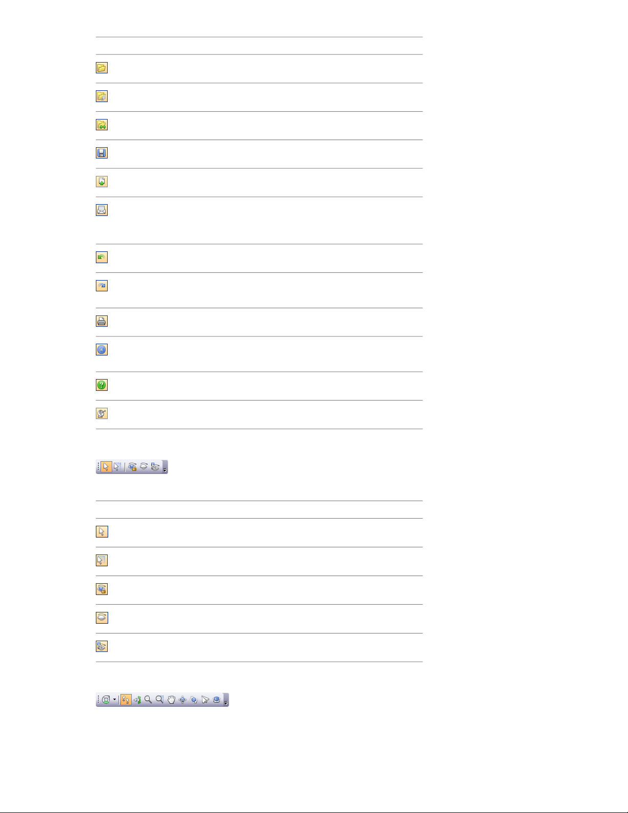
DescriptionButton
Displays the Open dialog box.
Displays the Open URL dialog box.
Displays the Merge dialog box.
Saves the currently open Navisworks file.
Displays the Publish dialog box.
Saves the currently open Navisworks file,
accesses your email program, and adds the
saved file as an email attachment.
Reverses the last performed operation.
Reverses the last operation performed by
the Undo command.
Displays the Print dialog box.
Displays copyright and license information
about your copy of Autodesk Navisworks.
Opens the Help system.
Opens the Communication Center.
Selection Tools Toolbar
This toolbar provides access to the selection commands, plus enables you to hide geometry objects.
DescriptionButton
Turns on select mode.
Turns on select box mode.
Toggles required mode for selected items.
Toggles hidden mode for selected items.
Toggles hidden mode for unselected items.
Navigation Mode Toolbar
Parts of Autodesk Navisworks Interface | 63
Page 76

This toolbar includes nine modes and six SteeringWheels for interactive navigation around your 3D models.
DescriptionButton
Selects the wheel.
Turns on walk mode.
Turns on look around mode.
Turns on zoom mode.
Turns on zoom box mode.
Turns on pan mode.
Turns on orbit mode.
Turns on examine mode.
Turns on fly mode.
Turns on turntable mode.
Rendering Style Toolbar
This toolbar controls the model appearance in Navisworks.
DescriptionButton
Selects lighting mode.
Selects rendering mode.
Toggles the rendering of surfaces.
Toggles the rendering of lines.
Toggles the rendering of points.
Toggles the rendering of snap points.
Toggles the rendering of 3D text.
Workspace Toolbar
64 | Chapter 4 Quick Start
Page 77

This toolbar gives you quick access to the Navisworks review and analysis tools.
DescriptionButton
Toggles the Redline Tools tool window.
Toggles the display of hyperlinks.
Toggles the display of smart tags.
Toggles the Measure Tools tool window.
Toggles the Viewpoints control bar.
Toggles the Sectioning toolbar.
Toggles the Plan Thumbnail control bar.
Toggles the Section Thumbnail control bar.
Toggles the Selection Tree control bar.
Toggles the Selection Sets control bar.
Toggles the Comments control bar.
Toggles the Find Comments dialog box.
Toggles the Find Items control bar.
Toggles the Properties control bar.
Toggles the Clash Detective tool window.
Toggles the Presenter tool window.
Toggles the TimeLiner tool window.
Toggles the Animator tool window.
Toggles the Scripter tool window.
Controls workspaces.
Model Views Toolbar
Parts of Autodesk Navisworks Interface | 65
Page 78

This toolbar controls the views in the Scene Area.
DescriptionButton
Splits your active scene view vertically.
Splits your active scene view horizontally.
Adds title bars to all custom scene views.
Sectioning Toolbar
This toolbar enables you to create a limited volume of your model.
DescriptionButton
Enables you to link two opposing section
planes together.
Displays the Set Sectioning Box Size dialog
box.
Restricts the section distance to the
bounding box limits of the objects selected
in the Scene Area
Displays the Sectioning Plane dialog box.
Enables/disables the current section plane
or box.
Deletes the current section plane.
Enables you to choose the alignment
method.
Animation Toolbar
This toolbar allows you to record viewpoint animations, play back object and viewpoint animations, and toggle
the scripting functionality.
DescriptionButton
Rewinds the current animation back to the
beginning.
Steps back a single animation frame or
keyframe.
66 | Chapter 4 Quick Start
Plays the current animation backwards.
Records the viewpoint animation.
Pauses the animation.
Page 79

DescriptionButton
Stops playing the current animation, and
rewinds it back to the beginning.
Plays the currently selected animation.
Steps one frame or keyframe forwards.
Fast forwards the current animation to the
end.
Toggles the Scripter engine on and off in
the Navisworks file.
Collaborate Bar Toolbar
This toolbar enables you to participate in design review sessions across a Local Area Network (LAN).
DescriptionButton
Starts Windows™ NetMeeting.
Enables you to rtake control of the session,
and become the ‘driver’.
Refreshes Navisworks data on all attendees
machines.
Object Manipulation Toolbar
This toolbar enables you to edit geometry in your model.
DescriptionButton
Toggles the display of the translation
gizmo.
Toggles the display of the rotation gizmo.
Toggles the display of the scale gizmo.
Enables you to apply color override.
Enables you to apply transparency override.
Navigation Tools Toolbar
Enables/disables snapping.
Parts of Autodesk Navisworks Interface | 67
Page 80
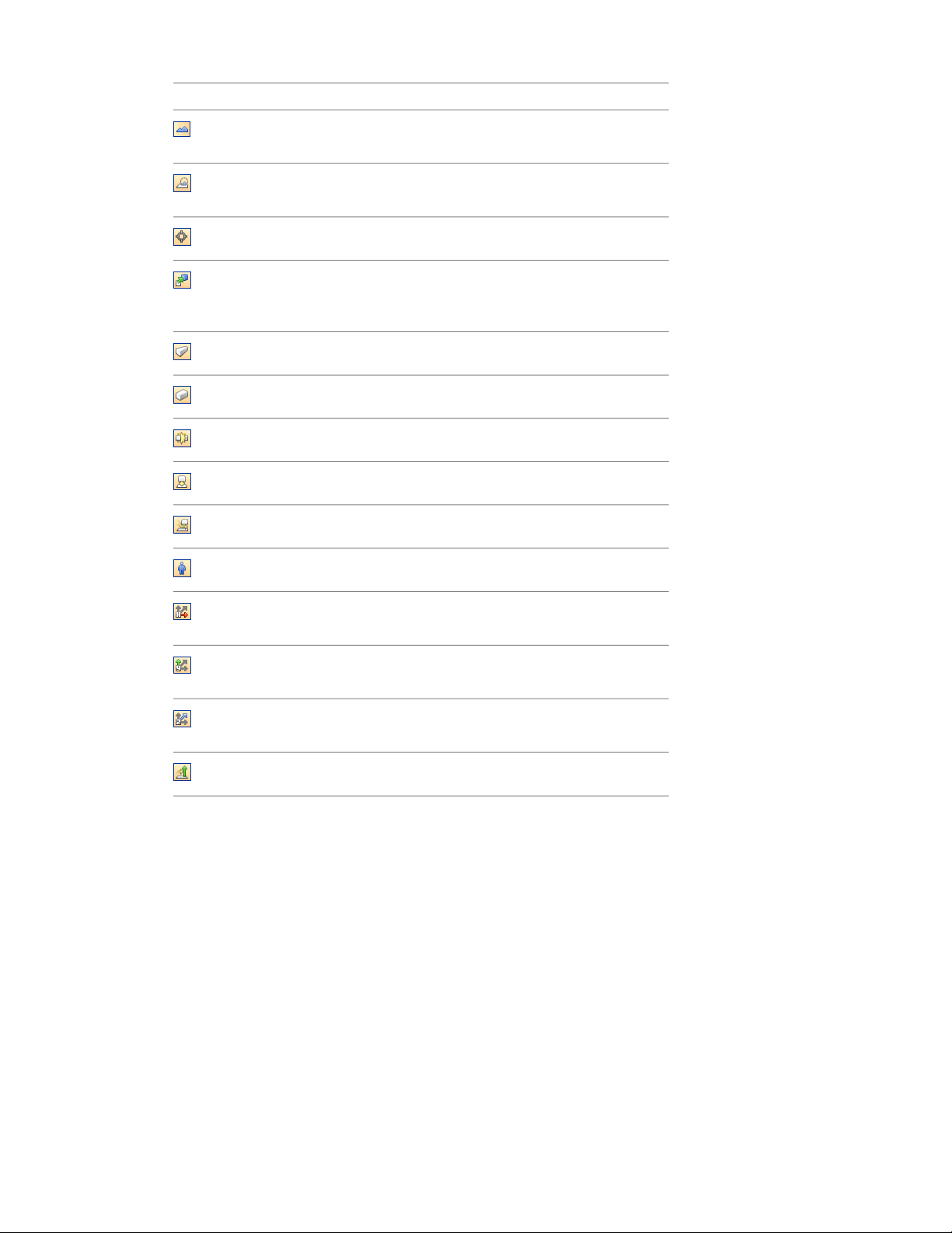
This toolbar enables you to control the camera during interactive navigation.
DescriptionButton
Dollies and pans the camera so that the
entire model is in the Scene View.
Zooms the camera so that the selected
item fills the Scene View.
Puts the Scene View into focus mode.
Holds the selected items. As you move
around the model, these objects will move
with you.
Uses a perspective camera.
Uses an orthographic camera.
Toggles collision.
Toggles gravity.
Toggles crouching.
Toggles third person view.
Aligns the current viewpoint with the X
axis.
Aligns the current viewpoint with the Y
axis.
Aligns the current viewpoint with the Z
axis.
Straightens the camera.
Scene Area
This is the area where you view and interact with your 3D models.
When you start Navisworks, the Scene Area contains only one scene view, but you can add more scene views,
if needed. Custom scene views are named "ViewX" where 'X' is the next available number.
68 | Chapter 4 Quick Start
Page 81
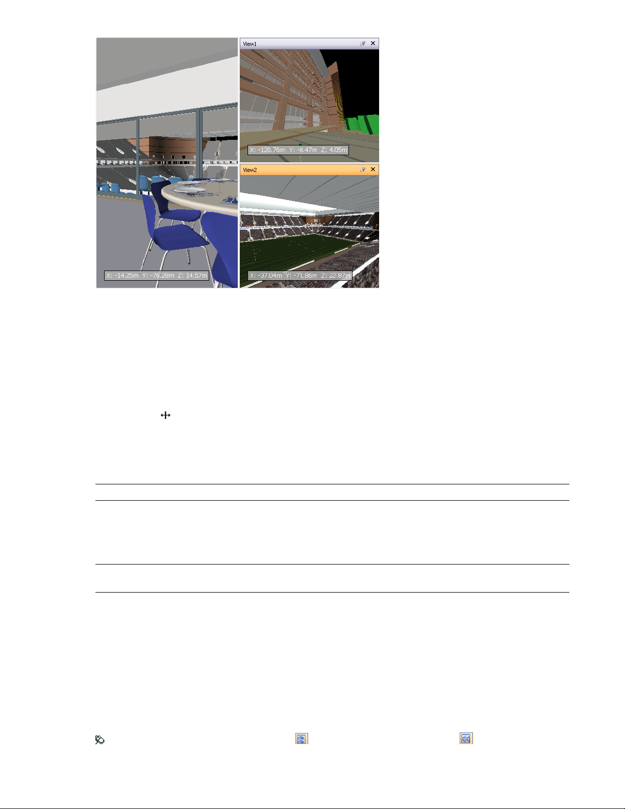
Looking at several views of your model simultaneously is useful when you compare lighting and rendering styles,
animate different parts of your model, and so on.
Only one scene view can be active at a time. A scene view becomes active as you work in it. If you left-click a
scene view, the scene view is activated and whatever you click is selected, or, if you click an empty area, everything
is deselected. Right-clicking a scene view activates it, and opens a shortcut menu.
Each scene view remembers the navigation mode being used. The recording and playback of animations only
occurs in the currently active view.
Each scene view can be resized. To resize scene views, move the cursor over the scene view intersection and drag
the splitter bar .
You can make custom scene views dockable. Dockable scene views have title bars, and can be moved, docked,
tiled, and auto hidden the same way as dockable windows. If you want to use several custom scene views, but
don't want to have any splits in the Scene Area, you can move them elsewhere. For instance, you can tile your
scene views on the Viewpoints control bar.
NOTE You cannot undock the default scene view.
Full Screen Mode
In full screen mode your current scene view takes up the full screen, and no interface controls are shown.
To interact with the model in the scene view, use the keyboard shortcuts and the shortcut menu.
TIP If you use two monitors, your default scene view is automatically placed on the primary display, and the interface
can be placed on the secondary display to control the interaction.
Scene View Content
Navisworks enables you to change the size of content displayed in a scene view. This can be of particular use if
you are composing a scene for image or animation export. By setting the content size to the same proportions
as your intended output, you can visualize exactly how it will look.
To create a custom scene view
■ To split your active scene view horizontally, click View ➤ Scene View ➤ Split Horizontal.
■ To split your active scene view vertically, click View ➤ Scene View ➤ Split Vertical.
Toolbar: Model Views ➤ Split Horizontal and Model Views ➤ Split Vertical
Parts of Autodesk Navisworks Interface | 69
Page 82

To make custom scene views dockable
■ Click View ➤ Scene View ➤ Toggle Title Bars.
All of your custom scene views now have title bars.
Toolbar: Model Views ➤ Toggle Title Bars
To delete a custom scene view
1 If your scene view is not dockable, click View ➤ Scene View ➤ Toggle Title Bars.
2 Click to close the scene view.
NOTE You cannot delete the default scene view.
To toggle full screen mode
■ Click View ➤ Scene View ➤ Full Screen.
Command entry: F11
Shortcut menu: Viewpoint ➤ Full Screen
To resize the content of the active scene view
1 Click View ➤ Scene View ➤ Window Size.
2 In the Window Size dialog box, Type drop-down list, select the sizing type.
■ Use View - makes the content fill the currently active scene view.
■ Explicit - defines the exact width and height for the content.
■ Use Aspect Ratio - uses the aspect ratio of the current scene view to automatically calculate the width
of the content when the height is entered, or the height of the content when the width is entered.
3 If you selected the Explicit option, enter the width and height for your content in pixels.
If you selected the Use Aspect Ratio, enter the width or height for your content in pixels.
4 Click OK.
Dockable Windows
Most Navisworks features are accessible from the dockable windows.
There are two types of dockable windows:
■ Control bars
■ Tool windows
To display a control bar, click View ➤ Control Bars on the Menu bar, and then choose from the list of available
control bars.
70 | Chapter 4 Quick Start
Page 83
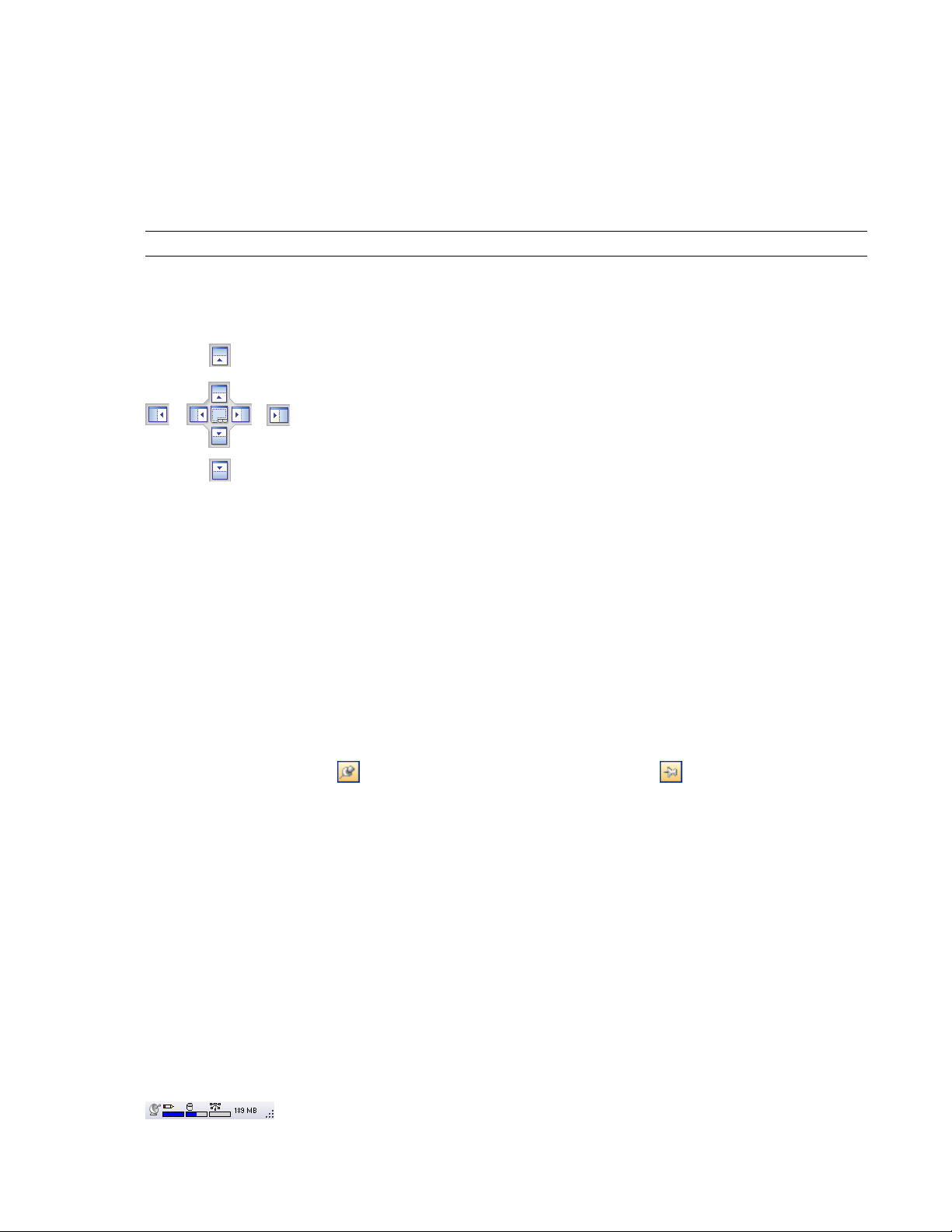
To display a tool window, click Tools on the Menu bar, and then choose from the list of available tool windows.
Alternatively, click the desired button on the Workspace toolbar.
Both types of windows can be moved and resized, and either floated in the Scene Area or docked. A docked
window shares one or more edges with adjacent windows and toolbars. If a shared edge is moved, the windows
change shape to compensate. You can also float windows anywhere on the screen, if necessary.
To undock and relocate a window, click and drag the title bars at the top or side of the window.
To prevent a window from automatically docking while you drag it, hold down the CTRL key.
NOTE You can quickly dock and undock a window by double-clicking the window's title bar.
Use the Docking Tool
When you drag a dockable window from its current location towards a new destination on the interface, a
docking tool appears.
The docking stickers point towards the four edges of the interface.
When the window you are dragging is close to the place where you want it to dock, move the mouse over the
corresponding area of the docking tool. You will see an outline of the window appear on the interface. To dock
the window there, release the mouse button.
Tile Windows
You can tile dockable windows on the interface. To do this, drag a window you want to tile over the window
where you want it to be placed. When a rectangular outline appears, release the mouse button.
Auto Hide Windows
You can auto hide dockable windows; this keeps the windows active while maximizing the amount of available
screen space. If auto-hide is active, the body of the window disappears when you move the cursor out of it,
leaving only the title bar visible. Move the cursor over the title bar to display the entire window again.
To switch auto-hide on, click on the title bar. To switch auto-hide off, click on the title bar.
The Shortcut Menu
Right-clicking a dockable window displays a shortcut menu of available commands. If you right-click a single
item, or select one or more items and right-click, this menu contains commands related to the items. If you
right-click an area that contains no items or data, the menu contains commands related to the dockable window,
if appropriate.
Status Bar
The Status bar appears at the bottom of the Autodesk Navisworks screen. As this is not a toolbar, it cannot be
customized or moved around.
The left-hand corner of the Status bar is used to display short instructions on how to use the Autodesk Navisworks
features.
In the right-hand corner of the Status bar there are four performance indicators that give you constant feedback
as to how well Autodesk Navisworks is performing on your machine, and the notification icon.
Parts of Autodesk Navisworks Interface | 71
Page 84

Notification Icon
Notification icon indicates whether any new information is available. Balloon notifications appear over this icon
whenever new Communication Center content is available. You can right-click this icon to turn off the
notifications, or to customize the Communication Center options.
Pencil Progress Bar
The progress bar under the left hand icon (pencil) indicates how much of the current view is drawn, that is how
much drop-out there is in the current viewpoint. When the progress bar is at 100%, the scene is completely
drawn, with no drop-out. The icon changes color when a redraw is in progress. Whilst the scene is being drawn,
the pencil will change to yellow. If there is too much data to handle and your machine cannot process this
quickly enough for Autodesk Navisworks, then the pencil changes to red, indicating a bottleneck.
Disk Progress Bar
The progress bar under the central icon (disk) indicates how much of the current model is loaded from disk, that
is how much is loaded into memory. When the progress bar is at 100%, the entire model, including geometry
and property information, is loaded into memory. The icon changes color when a file load is in progress. Whilst
data is being read, the disk changes to yellow. If there is too much data to handle and your machine cannot
process this quickly enough for Autodesk Navisworks, then the disk changes to red, indicating a bottleneck.
Web Server Progress Bar
The progress bar under the right hand icon (web server) indicates how much of the current model is downloaded,
that is how much has been downloaded from a web server. When the progress bar is at 100%, the entire model
has been downloaded. The icon changes color when a file load is in progress. Whilst data is being downloaded,
the web server changes to yellow. If there is too much data to handle and your machine cannot process this
quickly enough for Autodesk Navisworks, then the web server changes to red, indicating a bottleneck.
Memory Bar
The field to the right of the icons reports the amount of memory currently being used by Autodesk Navisworks.
This is reported in Megabytes (MB).
Undo/Redo Commands
You can undo or redo your actions in Autodesk Navisworks.
The default settings are adequate for regular Autodesk Navisworks usage, but you can adjust the amount of space
allocated to the undo/redo buffer, if necessary.
The Edit ➤ Undo and Edit ➤ Redo menu items state what type of action you can undo/redo.
To undo an action
■ Click Edit ➤ Undo on the Menu bar.
Command entry: CTRL + Z
Toolbar: Standard ➤ Undo
To redo an action
■ Click Edit ➤ Redo on the Menu bar.
Command entry: CTRL+Y
Toolbar: Standard ➤ Redo
72 | Chapter 4 Quick Start
Page 85

Autodesk Navisworks Workspaces
Workspaces are sets of toolbars and dockable windows that are grouped and organized so that you can work in
a custom, task-oriented design review environment.
Each workspace contains sets of toolbars and dockable windows with the tools required to perform a certain job,
making it easy to switch between design review layouts as necessary. For example, 'file aggregation', 'project
review', 'object animation' and 'interference detection' workspaces could be set up, saved and used as appropriate.
The workspaces can also be shared with other users. You could, for example, create separate workspaces for
occasional and power Navisworks users, or setup your own corporate standard.
Autodesk Navisworks comes with several pre-configured workspaces:
■ Safe Mode - selects the design review layout with the minimum features.
■ Extended - selects the design review layout recommended for advanced users.
■ Default - selects the design review layout recommended for users new to the program.
■ Classic - selects the design review layout used in Navisworks v5 and earlier.
You can use these workspaces as-is or modify them in accordance to your requirements. When you first start
Navisworks, the default workspace is used. You can choose a different workspace at any time by clicking View
➤ Workspaces, and then selecting the required workspace from the list.
Toolbar: Workspace ➤ Workspaces
To save current layout to a new workspace
1 Set up your design review layout. For example, you can close all toolbars except the Standard, Selection
Tools, Navigation Mode, and Workspace.
2 On the View menu, click Workspaces ➤ Save Workspace.
3 In the Save Current Workspace dialog box, enter a name for the new workspace. You can also select the
name of an existing workspace to overwrite it with your modified configuration.
4 Click Save.
To load a saved workspace into Navisworks
1 On the View menu, click Workspaces ➤ Load Workspace.
2 In the Load Workspace dialog box, browse to the folder containing the desired workspace, and select it.
Autodesk Navisworks Workspaces | 73
Page 86
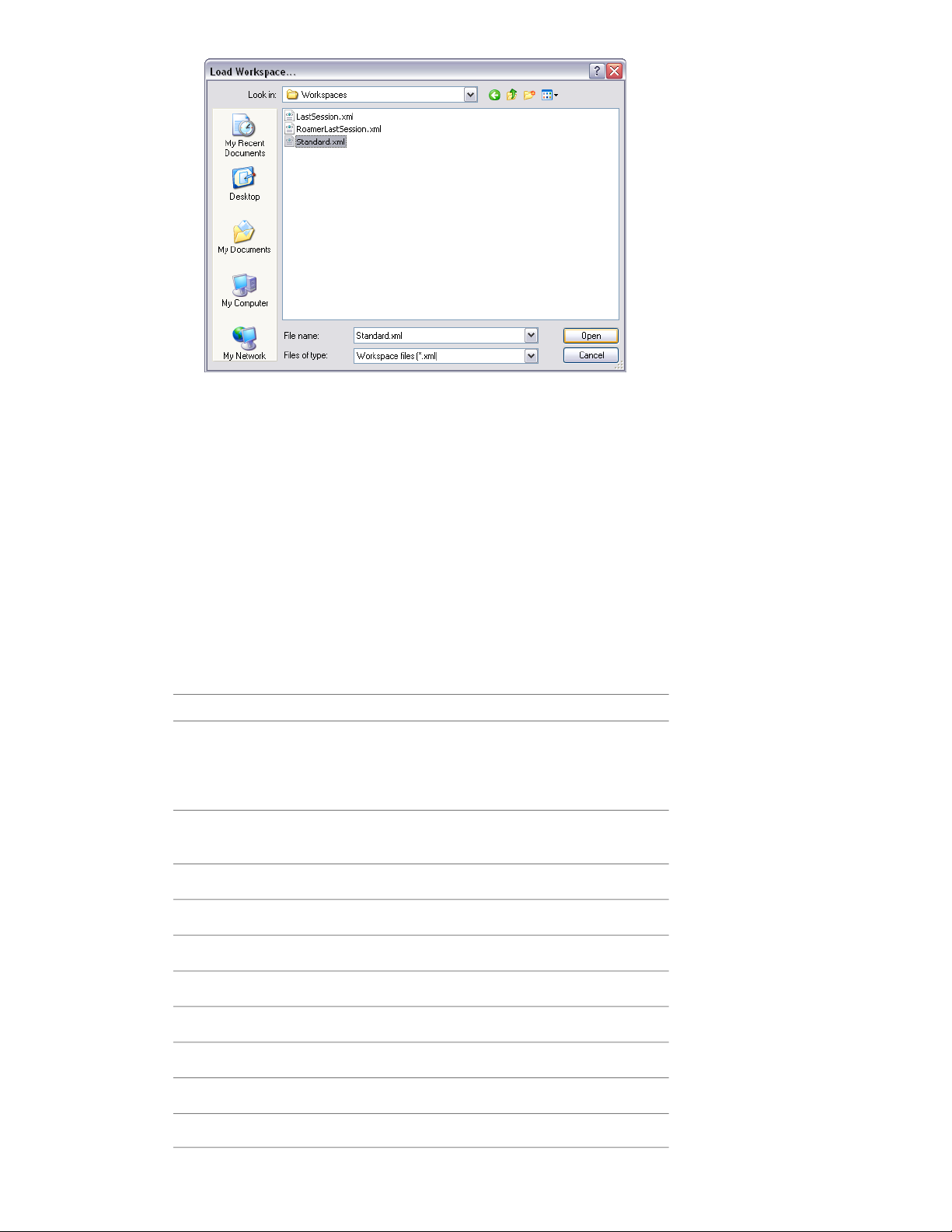
3 Click Open.
Default Keyboard Shortcuts
Keyboard shortcuts are keyboard alternatives you can use to initiate commands normally accessed with the
mouse.
For example, to open the Selection Tree, you can press CTRL + F12, to open the Find Comments dialog box, you
can press SHIFT + F4, and so on. Keyboard shortcuts offer a means to let you work faster and more efficiently.
Some dialog boxes or dockable windows can be closed with the same command used to open it.
Many keyboard shortcuts are already set for most commonly used actions. You can modify the default shortcuts
or add new shortcuts, if necessary.
Quick Reference
DescriptionDefault Keyboard Shortcut
ALT + F4
ALT + F6
74 | Chapter 4 Quick Start
Closes the currently active dockable window when it is undocked, or exits the application if the main application window
is active.
Switches between the dockable windows
when they are undocked.
Turns on turntable mode.CTRL + 0
Turns on select mode.CTRL + 1
Turns on walk mode.CTRL + 2
Turns on look around mode.CTRL + 3
Turns on zoom mode.CTRL + 4
Turns on zoom box mode.CTRL + 5
Turns on pan mode.CTRL + 6
Turns on orbit mode.CTRL + 7
Page 87

DescriptionDefault Keyboard Shortcut
Turns on examine mode.CTRL + 8
Turns on fly mode.CTRL + 9
Displays the Append dialog box.CTRL + A
CTRL + D
CTRL + N
CTRL + Y
Toggles collision mode. You must be in
appropriate navigation mode (that is, Walk
or Fly) for this keyboard shortcut to work.
Displays the Quick Find dialog box.CTRL + F
Toggles gravity mode.CTRL + G
Toggles hidden mode for selected items.CTRL + H
Displays the Merge dialog box.CTRL + M
Resets the program, and closes the currently open Navisworks file.
Displays the Open dialog box.CTRL + O
Displays the Print dialog box.CTRL + P
Toggles required mode for selected items.CTRL + R
Saves the currently open Navisworks file.CTRL + S
Toggles third person mode.CTRL + T
Reverses the last operation performed by
the Undo command.
CTRL + HOME
Reverses the last performed operation.CTRL + Z
Opens the Help system.CTRL + F1
Toggles the Camera Tilt control bar.CTRL + F7
Toggles the Sectioning toolbar.CTRL + F8
Toggles the Plan Thumbnail control bar.CTRL + F9
Toggles the Section Thumbnail control bar.CTRL + F10
Toggles the Viewpoints control bar.CTRL + F11
Toggles the Selection Tree control bar.CTRL + F12
Dollies and pans the camera so that the
entire model is in view.
Takes you to the next redline tag.CTRL + SHIFT + N
Takes you to the previous redline tag.CTRL + SHIFT + P
Default Keyboard Shortcuts | 75
Page 88

DescriptionDefault Keyboard Shortcut
HOME
F2
F3
F5
Enables view selected mode. This keyboard
shortcut only applies to the Scene Area
windows. This means it will only work
when this window has focus.
Deselects everything.ESC
Opens the Help system.F1
Renames the selected item, when appropriate.
Repeats the previously run quick find
search.
Refreshes your scene with the latest versions of currently loaded model files.
Toggles full screen mode.F11
Opens the last used SteeringWheel.Shift + W
Enables you to get context-sensitive help.SHIFT + F1
Toggles the Selection Sets control bar.SHIFT + F2
SHIFT + F10
Customize the Toolbars
You can customize the appearance and contents of the Autodesk Navisworks toolbars by using the Customize
dialog box.
To add a custom toolbar
1 Click Tools ➤ Customize.
2 In the Customize dialog box, Toolbars tab, click the New button.
3 Enter a name for the toolbar in the Toolbar Name box. By default, new toolbars are named "Custom X"
where 'X' is the next available number added to the list.
Toggles the Find Items control bar.SHIFT + F3
Toggles the Find Comments dialog box.SHIFT + F4
Toggles the Comments control bar.SHIFT + F6
Toggles the Properties control bar.SHIFT + F7
Opens a shortcut menu for the active
dockable window.
4 Click OK.
The new toolbar appears in the toolbar area.
76 | Chapter 4 Quick Start
Page 89
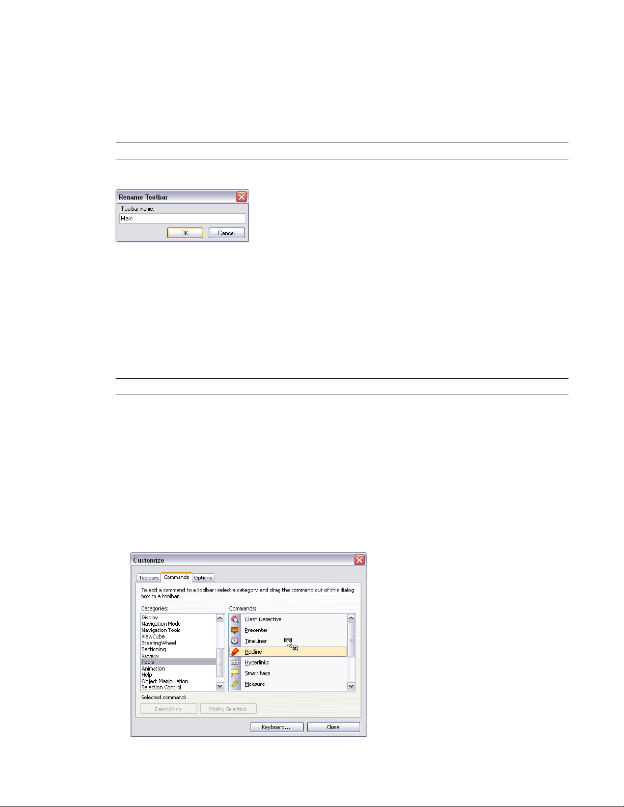
5 Close the Customize dialog box.
To rename a custom toolbar
1 Click Tools ➤ Customize.
2 In the Customize dialog box, Toolbars tab, click your toolbar.
3 Click Rename.
NOTE You can only rename custom toolbars.
4 Enter the new name for your toolbar.
5 Click OK.
6 Close the Customize dialog box.
To delete a custom toolbar
1 Click Tools ➤ Customize.
2 In the Customize dialog box, Toolbars tab, click the toolbar you don’t need.
3 Click Delete.
NOTE You can only delete custom toolbars.
4 Close the Customize dialog box.
To add commands
1 Click Tools ➤ Customize. This opens the Customize dialog box.
2 There are several ways to add commands to a toolbar or a menu:
■ In the Customize dialog box, Commands tab, click the desired category, and drag the command from
the commands list on to the toolbar. If the command has a default icon assigned to it (it is shown next
to the command in the command list), the icon will appear as a button on your toolbar. If no icon is
assigned to the command, the name of the command will appear as a button on the toolbar. For menus,
the command will appear exactly as it is shown in the command list.
Customize the Toolbars | 77
Page 90
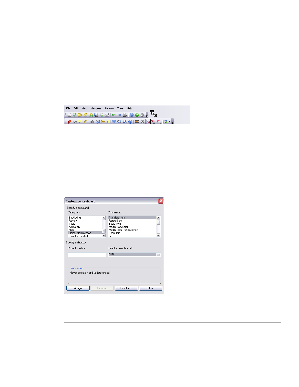
■ Drag the command from another menu or toolbar onto your toolbar or menu. This moves the command
from its original location into a new place.
■ Hold CTRL and drag the command from another menu or toolbar onto your toolbar or menu. This
creates a copy of the command, and does not remove the command from its original location.
3 If you want to edit the command’s appearance, right-click it on the toolbar or menu, and use options on
the shortcut menu.
4 Close the Customize dialog box.
To delete commands
1 Click Tools ➤ Customize. This opens the Customize dialog box.
2 Drag the command away from the menu or toolbar, until a cursor displays a small cross.
3 Release the left mouse button to delete the command.
4 Close the Customize dialog box.
To customize keyboard shortcuts
1 Click Tools ➤ Customize.
2 In the Customize dialog box, click the Keyboard button.
3 In the Customize Keyboard dialog box, use the Categories and Commands lists to find desired command.
4 Click the command, and choose a shortcut in the Select a New Shortcut drop-down list.
5 Click Assign.
NOTE Clicking Remove removes the shortcut assignment for the selected command, and clicking Reset All restores
the default shortcut assignments.
6 Close the dialog boxes.
78 | Chapter 4 Quick Start
Page 91
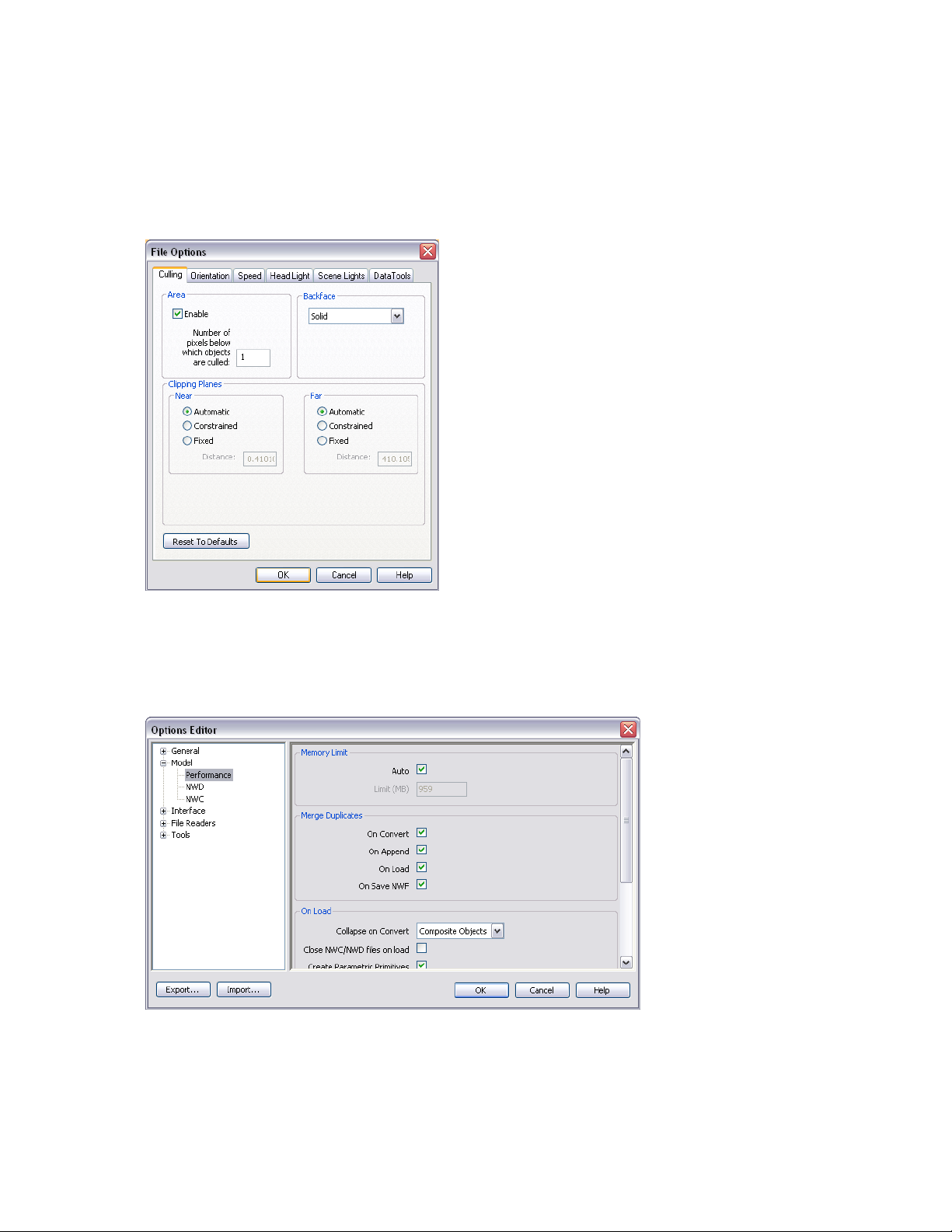
Autodesk Navisworks Options
There are two types of options: File Options and Global Options.
File Options
For each Autodesk Navisworks file (.NWF and .NWD), you can adjust the model appearance and the speed of
navigation around it. File options are stored with Autodesk Navisworks files (.nwf or .nwd), and reloaded each
time you open these files.
The File Options dialog box is used to customize various file options, and can be accessed from the Tools menu.
Global Options
Global options, on the other hand, are set for all Autodesk Navisworks sessions. The Options Editor can be
accessed from the Tools menu, or it can be launched as a separate application. To do this, click Start ➤ Programs
➤ Autodesk ➤ Navisworks Manage 2010 ➤ Options Editor. The options are grouped together, and presented
in a tree structure, making it quicker to find and change them.
Global options can be exported and imported, making it quick and easy for project managers, or systems
administrators, to ensure the Autodesk Navisworks settings on all machines are identical.
To configure file options
1 Click Tools ➤ File Options.
Autodesk Navisworks Options | 79
Page 92

2 Use the File Options dialog box to customize various file settings.
3 Click OK to save the changes.
See also:
■ “File Options Dialog Box” on page 401
To configure global options
1 Click Tools ➤ Global Options.
2 In the Options Editor, expand the desired node, and click the option you want to configure.
3 Click OK to save the changes.
See also:
■ “Options Editor” on page 405
To export global options
1 Click Tools ➤ Global Options.
2 In the Options Editor, click the Export button.
3 In the Select Options to Export dialog box, select the check boxes for all options you want to be exported
(or 'serialized'). If an option cannot be exported, it is greyed out.
TIP To quickly select/deselect all options for a given category, use the top-level check boxes. For example, selecting
the General check box, instantly selects all options under this node.
4 Click OK to export the selected settings.
5 In the Save As dialog box, enter a name for the settings file. You can also select the name of an existing
settings file to overwrite it with your modified configuration.
80 | Chapter 4 Quick Start
Page 93

6 Click Save.
7 Click OK to close the Options Editor.
To import global options
1 Click Tools ➤ Global Options.
2 In the Options Editor, click the Import button.
3 In the Open dialog box, browse to the folder containing the settings file, select it, and click Open.
4 Click OK to close the Options Editor.
Environment Options
You can adjust the number of recent file shortcuts stored by Autodesk Navisworks.
To configure environment options
1 Click Tools ➤ Global Options.
2 In the Options Editor, expand the General node, and click the Environment option.
Environment Options | 81
Page 94
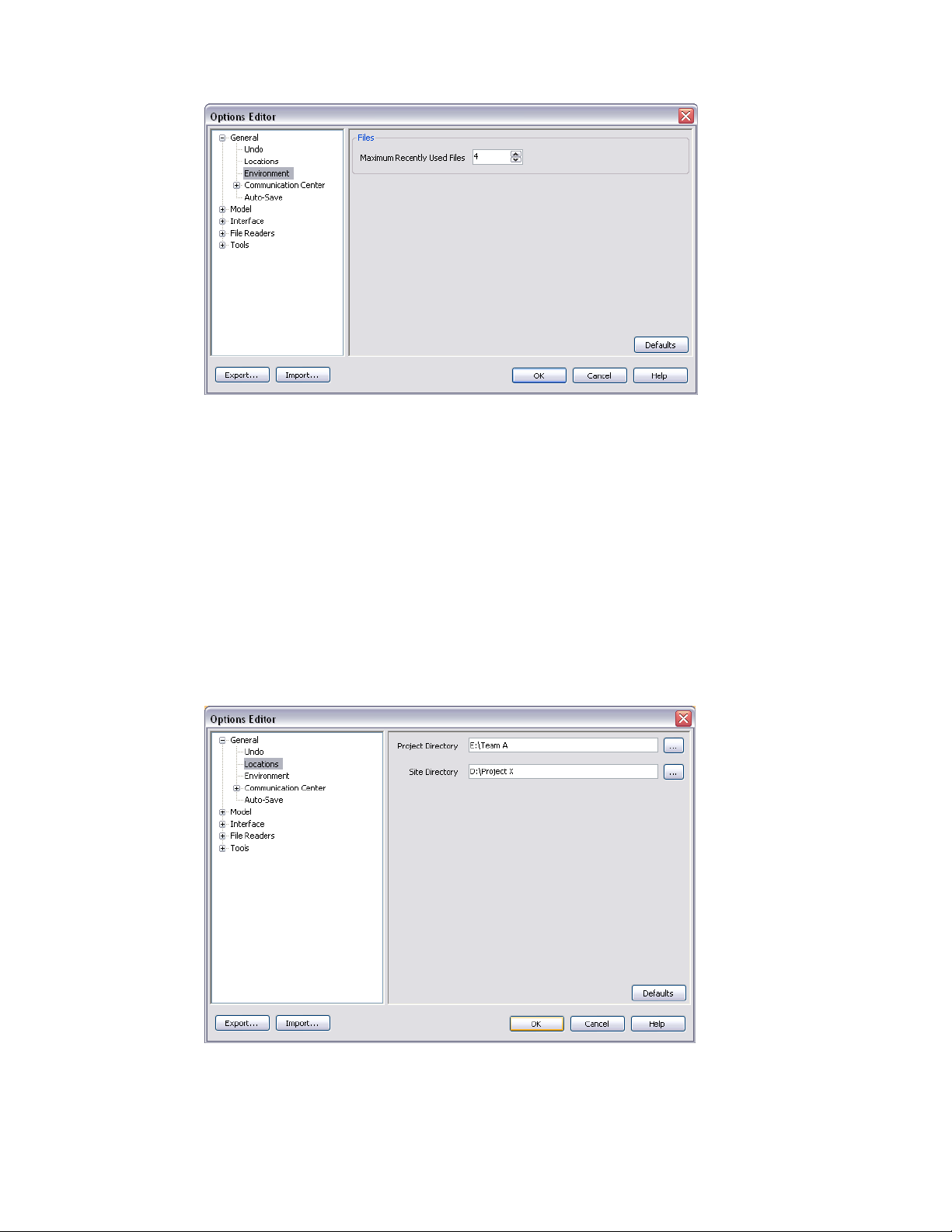
3 On the Environment page, enter the desired number into the Maximum Recently Used Files box. By default,
shortcuts to the four most recently opened files can be displayed.
4 Click OK.
Location Options
These options enable centralized sharing of global Autodesk Navisworks settings, workspaces, datatools, avatars,
Clash Detective rules, Presenter archives, custom Clash Detective tests, object animation scripts, and so on, with
other users.
The settings can be shared across an entire project site, or across a specific project group depending on the
required level of granularity.
To configure location options
1 Click Tools ➤ Global Options.
2 Expand the General node in the Options Editor, and click the Locations option.
3 In the Project Directory box, browse to the directory that contains the Autodesk Navisworks settings specific
to your project group.
4 In the Site Directory box, browse to the directory that contains the Autodesk Navisworks settings standard
across the entire project site.
82 | Chapter 4 Quick Start
Page 95

5 Click OK.
NOTE When you run Autodesk Navisworks for the first time, the settings are picked up from the installation directory.
Subsequently, Autodesk Navisworks examines the current user profile and the all users profile on the local machine,
and then checks the settings in the Project Directory and the Site Directory. The files in the Project Directory take
precedence.
Display Units
Display units determine the scale of your model in Navisworks.
Display units are used to measure geometry in your scene, align appended models, set tolerances for clash
detection, set texture sizes and so on.
When you open CAD and laser scan files, Autodesk Navisworks reads the file units directly from the files. If this
is not possible (for example, the file is unitless), Autodesk Navisworks uses the default file units configured for
that file type in the Global Options whenever possible. Loaded files are scaled appropriately to the configured
display units.
It is possible to rescale the file units, if they are found to be incorrect for the scene.
To customize display units
1 Click Tools ➤ Global Options.
2 Expand the Interface node in the Options Editor, and click the Display Units option.
Profiles
3 Select the Linear Units from the drop-down list. Be sure to choose the exact format required.
4 Select the Angular Units from the drop-down list.
5 Enter the number of decimal places you want to see throughout the interface for your units in the Decimal
Places box. If the unit chosen is a fractional unit, rather than a decimal unit, then you have the choice of
what level of fraction to display the units from the Fractional Display Precision drop-down list.
6 Click OK.
Autodesk Navisworks can be adjusted to your level of CAD technical knowledge.
By default, a standard profile is used. If necessary, you can use a developer profile to display additional object
properties.
Display Units | 83
Page 96

To use a developer profile
1 Click Tools ➤ Global Options.
2 Expand the Interface node, and click the Developer option.
3 Select the Show Internal Properties check box to add additional object properties to the Properties control
bar.
4 Click OK.
Search Directories
Autodesk Navisworks searches for a variety of configuration files in subdirectories of three standard directories.
These files can be overridden on a per user, all users or per installation basis. The search directories are:
■ Application Data\Autodesk Navisworks Manage 2010 within the current user profile. For example, C:\Documents
and Settings\user\Application Data\Autodesk Navisworks Manage 2010 where user is the name of the current
user.
■ Application Data\Autodesk Navisworks Manage 2010 within the all users default profile. For example,
C:\Documents and Settings\All Users\Application Data\Autodesk Navisworks Manage 2010.
■ Within the Navisworks install directory. For example, C:\Program Files\Autodesk Navisworks Manage 2010.
84 | Chapter 4 Quick Start
Page 97

Get a Whole-Project View
85
Page 98

86 | Part 2 Get a Whole-Project View
Page 99

Work with Files
In Autodesk Navisworks you can open files originated from a variety of CAD
applications.
You can combine these files together, and create a single Autodesk Navisworks
file with a whole-project view of your model. This file brings together geometry
and data created by multi-disciplinary teams, and enables you to explore and
review complex models in real-time.
Native File Formats
Autodesk Navisworks has three native file formats: NWD, NWF, and
NWC.
NWD File Format
An NWD file contains all model geometry together with review
markups. You can think of an NWD file as a snapshot of the current
state of the model.
NWD files are very small, as they compress the CAD data by up to
80% of the original size.
NWF File Format
An NWF file contains links to the original native files (as listed on
the Selection Tree) together with review markups. No model
geometry is saved with this file format; this makes an NWF
considerably smaller in size than an NWD.
5
NWC File Format (Cache Files)
By default, when you open or append any native CAD or laser scan
files in Autodesk Navisworks, a cache file is created in the same
directory and with the same name as the original file, but with an
.nwc extension.
NWC files are smaller than the original files, and speed up your
access to commonly used files. When you next open file or append
file in Autodesk Navisworks, the data is read from the corresponding
cache file if it is newer than the original file. If the cache file is older,
which means the original file has changed, Autodesk Navisworks
converts the updated file, and creates a new cache file for it.
See also:
■ “NWC File Options” on page 409
87
Page 100

■ “NWD File Options” on page 409
Compatible CAD Applications
The table below is provided as a quick reference only, and does not contain an exhaustive list of compatible
CAD applications. For additional information, please refer to the Features and Specifications section on our
website http://www.autodesk.com/navisworks.
File FormatsApplication
DWG, DXF, 3DSAutodesk AutoCAD
DWG, DXF, 3DSAutodesk ADT/AutoCAD Architecture
DWG, DXF, 3DSAutodesk Building Systems/AutoCAD MEP
IPT, IAM, IPJ, IGES, STEPAutodesk Inventor
DWG, DXF, 3DSAutodesk AutoCAD Civil 3D
DWG, DXF, 3DS, VRMLAutodesk MDT
DWG, DXF, DGNAutodesk Revit
DWG, DXF, DGNAutodesk Revit Building/Revit Architecture
DWG, DXF, DGN, CIS/2Autodesk Revit Structure
DWG, DXF, DGNAutodesk Revit Systems/Revit MEP
DWG, DXF, 3DS, IGESAutodesk 3DS MAX
DWG, DXF, 3DSAutodesk VIZ
DXF, IGES, VRMLAutodesk Maya
DGN, DWG, DXFBentley AutoPLANT
DGN, DWG, DXF, IGES, VRMLBentley MicroStation SE
DGN, DWG, DXF, IGES, STEP, VRMLBentley MicroStation J
DGN, DWG, DXF, IGES, STEP, VRMLBentley MicroStation
DGN, DWG, DXF, IGES, STEP, VRMLBentley Triforma J
DGN, DWG, DXF, IGES, STEP, VRMLBentley Triforma
DWG, DXF, DGN, IFCGraphisoft ArchiCAD
DWG, DXF, DGNGraphisoft Constructor
88 | Chapter 5 Work with Files
DXFAceCad StruCad
DWG, DXF, 3DS, IGES, STL, VRMLauto.des.sys form.z
DWG, DXF, 3DSAEC CADPIPE
RVMAVEVA PDMS
 Loading...