

Page 1

AutoCAD LT 2013
User's Guide
January 2012
Page 2

©
2012 Autodesk, Inc. All Rights Reserved. Except as otherwise permitted by Autodesk, Inc., this publication, or parts thereof, may not
be reproduced in any form, by any method, for any purpose.
Certain materials included in this publication are reprinted with the permission of the copyright holder.
Trademarks
The following are registered trademarks or trademarks of Autodesk, Inc., and/or its subsidiaries and/or affiliates in the USA and other countries:
123D, 3ds Max, Algor, Alias, Alias (swirl design/logo), AliasStudio, ATC, AUGI, AutoCAD, AutoCAD Learning Assistance, AutoCAD LT, AutoCAD
Simulator, AutoCAD SQL Extension, AutoCAD SQL Interface, Autodesk, Autodesk Homestyler, Autodesk Intent, Autodesk Inventor, Autodesk
MapGuide, Autodesk Streamline, AutoLISP, AutoSketch, AutoSnap, AutoTrack, Backburner, Backdraft, Beast, Beast (design/logo) Built with
ObjectARX (design/logo), Burn, Buzzsaw, CAiCE, CFdesign, Civil 3D, Cleaner, Cleaner Central, ClearScale, Colour Warper, Combustion,
Communication Specification, Constructware, Content Explorer, Creative Bridge, Dancing Baby (image), DesignCenter, Design Doctor, Designer's
Toolkit, DesignKids, DesignProf, DesignServer, DesignStudio, Design Web Format, Discreet, DWF, DWG, DWG (design/logo), DWG Extreme,
DWG TrueConvert, DWG TrueView, DWFX, DXF, Ecotect, Evolver, Exposure, Extending the Design Team, Face Robot, FBX, Fempro, Fire, Flame,
Flare, Flint, FMDesktop, Freewheel, GDX Driver, Green Building Studio, Heads-up Design, Heidi, Homestyler, HumanIK, IDEA Server, i-drop,
Illuminate Labs AB (design/logo), ImageModeler, iMOUT, Incinerator, Inferno, Instructables, Instructables (stylized robot design/logo),Inventor,
Inventor LT, Kynapse, Kynogon, LandXplorer, LiquidLight, LiquidLight (design/logo), Lustre, MatchMover, Maya, Mechanical Desktop, Moldflow,
Moldflow Plastics Advisers, Moldflow Plastics Insight, Moldflow Plastics Xpert, Moondust, MotionBuilder, Movimento, MPA, MPA (design/logo),
MPI, MPI (design/logo), MPX, MPX (design/logo), Mudbox, Multi-Master Editing, Navisworks, ObjectARX, ObjectDBX, Opticore, Pipeplus, Pixlr,
Pixlr-o-matic, PolarSnap, PortfolioWall, Powered with Autodesk Technology, Productstream, ProMaterials, RasterDWG, RealDWG, Real-time
Roto, Recognize, Render Queue, Retimer, Reveal, Revit, RiverCAD, Robot, Scaleform, Scaleform GFx, Showcase, Show Me, ShowMotion,
SketchBook, Smoke, Softimage, Softimage|XSI (design/logo), Sparks, SteeringWheels, Stitcher, Stone, StormNET, Tinkerbox, ToolClip, Topobase,
Toxik, TrustedDWG, U-Vis, ViewCube, Visual, Visual LISP, Voice Reality, Volo, Vtour, WaterNetworks, Wire, Wiretap, WiretapCentral, XSI.
All other brand names, product names or trademarks belong to their respective holders.
Disclaimer
THIS PUBLICATION AND THE INFORMATION CONTAINED HEREIN IS MADE AVAILABLE BY AUTODESK, INC. "AS IS." AUTODESK, INC. DISCLAIMS
ALL WARRANTIES, EITHER EXPRESS OR IMPLIED, INCLUDING BUT NOT LIMITED TO ANY IMPLIED WARRANTIES OF MERCHANTABILITY OR
FITNESS FOR A PARTICULAR PURPOSE REGARDING THESE MATERIALS.
Page 3

Contents
Chapter 1 Get Information . . . . . . . . . . . . . . . . . . . . . . . . . . 1
Find the Information You Need . . . . . . . . . . . . . . . . . . . . . . 1
Access and Search the Product Help . . . . . . . . . . . . . . . . . 1
Learn the Product . . . . . . . . . . . . . . . . . . . . . . . . . . . 2
View the Product Readme . . . . . . . . . . . . . . . . . . . . . . 3
Join the Customer Involvement Program . . . . . . . . . . . . . . 3
Join the Customer Involvement Program . . . . . . . . . . . 4
Get Information from Drawings . . . . . . . . . . . . . . . . . . . . . . 4
Obtain General Drawing Information . . . . . . . . . . . . . . . . 4
Chapter 2 The User Interface . . . . . . . . . . . . . . . . . . . . . . . . . 7
Start a Command . . . . . . . . . . . . . . . . . . . . . . . . . . . . . . 7
Parts of the User Interface . . . . . . . . . . . . . . . . . . . . . . 7
The Menu Bar . . . . . . . . . . . . . . . . . . . . . . . . . . . . . 8
The Tool Sets Palette . . . . . . . . . . . . . . . . . . . . . . . . . 8
The Command Line . . . . . . . . . . . . . . . . . . . . . . . . . 10
Overview of Using the Command Line . . . . . . . . . . . . 10
Enter Commands on the Command Line . . . . . . . . . . 11
Enter System Variables on the Command Line . . . . . . . . 13
Switch Between Dialog Boxes and the Command
Line . . . . . . . . . . . . . . . . . . . . . . . . . . . . . 14
View and Edit Within the Command History . . . . . . . . 14
Work with Shortcut Menus . . . . . . . . . . . . . . . . . . . . . 15
iii
Page 4

About Keyboard Shortcuts . . . . . . . . . . . . . . . . . . . . . 16
Control the Drawing Area Interface . . . . . . . . . . . . . . . . . . . 22
Interface Themes and Background Color . . . . . . . . . . . . . . 22
Interface Themes and Background Color . . . . . . . . . . . 22
Cursors in the Drawing Area . . . . . . . . . . . . . . . . . . . . 23
Selection Style . . . . . . . . . . . . . . . . . . . . . . . . . . . . 23
The UCS Icon . . . . . . . . . . . . . . . . . . . . . . . . . . . . 24
The Coordinates Display . . . . . . . . . . . . . . . . . . . . . . 25
Model Space and Layouts . . . . . . . . . . . . . . . . . . . . . . 25
Control Status, Layers, Properties, and Content . . . . . . . . . . . . . 26
The Status Bar . . . . . . . . . . . . . . . . . . . . . . . . . . . . 26
The Status Bar . . . . . . . . . . . . . . . . . . . . . . . . . 27
The Layers Palette . . . . . . . . . . . . . . . . . . . . . . . . . . 27
The Layers Palette . . . . . . . . . . . . . . . . . . . . . . . 29
The Properties Inspector . . . . . . . . . . . . . . . . . . . . . . 30
The Content Palette . . . . . . . . . . . . . . . . . . . . . . . . . 31
Customize the Drawing Environment . . . . . . . . . . . . . . . . . . 32
Set Interface Options . . . . . . . . . . . . . . . . . . . . . . . . 32
Set Up the Drawing Area . . . . . . . . . . . . . . . . . . . 32
Specify the Behavior of Palettes . . . . . . . . . . . . . . . . 33
Performance Tuning . . . . . . . . . . . . . . . . . . . . . 34
Customize Startup . . . . . . . . . . . . . . . . . . . . . . . . . . 34
Chapter 3 Start and Save Drawings . . . . . . . . . . . . . . . . . . . . . 37
Start a Drawing . . . . . . . . . . . . . . . . . . . . . . . . . . . . . . 37
Overview of Starting a New Drawing . . . . . . . . . . . . . . . . 37
Specify Units and Unit Formats . . . . . . . . . . . . . . . . . . . 38
Determine the Units of Measurement . . . . . . . . . . . . 38
Set the Unit Format Conventions . . . . . . . . . . . . . . 39
Use a Drawing Template File . . . . . . . . . . . . . . . . . . . . 40
Add Identifying Information to Drawings . . . . . . . . . . . . . 41
Open or Save a Drawing . . . . . . . . . . . . . . . . . . . . . . . . . . 41
Open a Drawing . . . . . . . . . . . . . . . . . . . . . . . . . . . 41
Work with Multiple Open Drawings . . . . . . . . . . . . . . . . 44
Preview Open Drawings and Layouts . . . . . . . . . . . . . 44
Switch Between Open Drawings . . . . . . . . . . . . . . . 45
Switch Between Layouts in the Current Drawing . . . . . . 45
Transfer Information between Open Drawings . . . . . . . . 45
Save a Drawing . . . . . . . . . . . . . . . . . . . . . . . . . . . 46
Find a Drawing File . . . . . . . . . . . . . . . . . . . . . . . . . 49
Specify Search Paths and File Locations . . . . . . . . . . . . . . 49
Repair, Restore, or Recover Drawing Files . . . . . . . . . . . . . . . . . 50
Repair a Damaged Drawing File . . . . . . . . . . . . . . . . . . . 50
Create and Restore Backup Files . . . . . . . . . . . . . . . . . . 52
Recover from a System Failure . . . . . . . . . . . . . . . . . . . 53
iv | Contents
Page 5

Chapter 4 Control the Drawing Views . . . . . . . . . . . . . . . . . . . . 55
Change Views . . . . . . . . . . . . . . . . . . . . . . . . . . . . . . . 55
Pan or Zoom a View . . . . . . . . . . . . . . . . . . . . . . . . . 55
Save and Restore Views . . . . . . . . . . . . . . . . . . . . . . . 57
Control the 3D Projection Style . . . . . . . . . . . . . . . . . . . 58
Define a Parallel Projection . . . . . . . . . . . . . . . . . . 58
Choose Preset 3D Views . . . . . . . . . . . . . . . . . . . . 59
Define a 3D View with Coordinate Values or Angles . . . . . 59
Change to a View of the XY Plane . . . . . . . . . . . . . . 60
Hide Lines or Shade 3D Objects . . . . . . . . . . . . . . . . . . . 60
Hide Lines in 3D Objects . . . . . . . . . . . . . . . . . . . 60
Add Simple Shading to 3D Objects . . . . . . . . . . . . . . 61
Display Multiple Views in Model Space . . . . . . . . . . . . . . . . . . 63
Set Model Space Viewports . . . . . . . . . . . . . . . . . . . . . 63
Select and Use the Current Viewport . . . . . . . . . . . . . . . . 65
Save and Restore Model Layout Viewport Arrangements . . . . . 65
Chapter 5 Organize Drawings and Layouts . . . . . . . . . . . . . . . . . 67
Create Single-View Drawings (Model Space) . . . . . . . . . . . . . . . 67
Quick Start for Model Space Drafting . . . . . . . . . . . . . . . . 67
Draw, Scale, and Annotate in Model Space . . . . . . . . . . . . . 68
Create Multiple-View Drawing Layouts (Paper Space) . . . . . . . . . . 71
Quick Start for Layouts . . . . . . . . . . . . . . . . . . . . . . . 71
Understand the Layout Process . . . . . . . . . . . . . . . . . . . 71
Work with Model Space and Paper Space . . . . . . . . . . . . . . 72
Work in Model Space . . . . . . . . . . . . . . . . . . . . . 73
Work on a Named Layout . . . . . . . . . . . . . . . . . . . 73
Access Model Space from a Layout Viewport . . . . . . . . . 74
Create and Modify Layout Viewports . . . . . . . . . . . . . . . . 75
Control Views in Layout Viewports . . . . . . . . . . . . . . . . . 76
Scale Views in Layout Viewports . . . . . . . . . . . . . . . 77
Control Visibility in Layout Viewports . . . . . . . . . . . . 78
Scale Linetypes in Layout Viewports . . . . . . . . . . . . . 81
Align Views in Layout Viewports . . . . . . . . . . . . . . . 81
Rotate Views in Layout Viewports . . . . . . . . . . . . . . 82
Reuse Layouts and Layout Settings . . . . . . . . . . . . . . . . . 83
Work with Layouts in a Project . . . . . . . . . . . . . . . . . . . . . . 84
Quick Start for Projects . . . . . . . . . . . . . . . . . . . . . . . 84
Understand the Project Manager Interface . . . . . . . . . . . . . 85
Create and Manage a Project . . . . . . . . . . . . . . . . . . . . 86
Create a Project . . . . . . . . . . . . . . . . . . . . . . . . 87
Create and Modify Layouts in a Project . . . . . . . . . . . 89
Work with Views on Layouts . . . . . . . . . . . . . . . . . 91
Organize a Project with Groups . . . . . . . . . . . . . . . . 91
Contents | v
Page 6

Include Information with Projects, Groups, Layouts, and
Views . . . . . . . . . . . . . . . . . . . . . . . . . . . . 92
Publish Layouts and Projects . . . . . . . . . . . . . . . . . . . . 93
Use Projects in a Team . . . . . . . . . . . . . . . . . . . . . . . 94
Use Projects in a Multiple Operating System Environment . . . . 96
Chapter 6 Create and Modify Objects . . . . . . . . . . . . . . . . . . . . 99
Control the Properties of Objects . . . . . . . . . . . . . . . . . . . . . 99
Work with Object Properties . . . . . . . . . . . . . . . . . . . . 99
Overview of Object Properties . . . . . . . . . . . . . . . . 99
Display and Change the Properties of Objects . . . . . . . 100
Copy Properties Between Objects . . . . . . . . . . . . . . 101
Work with Layers . . . . . . . . . . . . . . . . . . . . . . . . . 101
Overview of Layers . . . . . . . . . . . . . . . . . . . . . . 101
Use Layers to Manage Complexity . . . . . . . . . . . . . 102
Create and Name Layers . . . . . . . . . . . . . . . . . . . 105
Change Layer Settings and Layer Properties . . . . . . . . 106
Override Layer Properties in Viewports . . . . . . . . . . . 107
Group and Sort the List of Layers . . . . . . . . . . . . . . 109
Reconcile New Layers . . . . . . . . . . . . . . . . . . . . 113
Work with Layer States . . . . . . . . . . . . . . . . . . . 113
Work with Colors . . . . . . . . . . . . . . . . . . . . . . . . . 116
Set the Current Color . . . . . . . . . . . . . . . . . . . . 116
Change the Color of an Object . . . . . . . . . . . . . . . 117
Use Color Books . . . . . . . . . . . . . . . . . . . . . . . 118
Work with Linetypes . . . . . . . . . . . . . . . . . . . . . . . . 119
Overview of Linetypes . . . . . . . . . . . . . . . . . . . . 119
Load Linetypes . . . . . . . . . . . . . . . . . . . . . . . . 120
Set the Current Linetype . . . . . . . . . . . . . . . . . . . 120
Change the Linetype of an Object . . . . . . . . . . . . . 121
Control Linetype Scale . . . . . . . . . . . . . . . . . . . . 122
Display Linetypes on Short Segments and Polylines . . . . 123
Control Lineweights . . . . . . . . . . . . . . . . . . . . . . . . 123
Overview of Lineweights . . . . . . . . . . . . . . . . . . 124
Display Lineweights . . . . . . . . . . . . . . . . . . . . . 125
Set the Current Lineweight . . . . . . . . . . . . . . . . . 126
Change the Lineweight of an Object . . . . . . . . . . . . 126
Control the Display Properties of Certain Objects . . . . . . . . 127
Control the Display of Polylines, Hatches, Gradient Fills,
Lineweights, and Text . . . . . . . . . . . . . . . . . . . 127
Control the Transparency of Objects . . . . . . . . . . . . 129
Control How Overlapping Objects Are Displayed . . . . . . 129
Control the Display of Objects . . . . . . . . . . . . . . . 130
Use Precision Tools . . . . . . . . . . . . . . . . . . . . . . . . . . . . 130
Work with the User Coordinate System (UCS) . . . . . . . . . . 130
Overview of the User Coordinate System (UCS) . . . . . . 130
vi | Contents
Page 7

Control the User Coordinate System (UCS) . . . . . . . . . 131
Work with Named UCS Definitions and Preset
Orientations . . . . . . . . . . . . . . . . . . . . . . . . 132
Control the Display of the User Coordinate System
Icon . . . . . . . . . . . . . . . . . . . . . . . . . . . . 132
Enter Coordinates to Specify Points . . . . . . . . . . . . . . . . 134
Overview of Coordinate Entry . . . . . . . . . . . . . . . . 134
Enter 2D Coordinates . . . . . . . . . . . . . . . . . . . . 135
Enter 3D Coordinates . . . . . . . . . . . . . . . . . . . . 139
Use Dynamic Input . . . . . . . . . . . . . . . . . . . . . . . . 144
Snap to Locations on Objects (Object Snaps) . . . . . . . . . . . 146
Use Object Snaps . . . . . . . . . . . . . . . . . . . . . . . 147
The Object Snap Menu . . . . . . . . . . . . . . . . . . . 148
Set Visual Aids for Object Snaps (AutoSnap) . . . . . . . . 148
Override Object Snap Settings . . . . . . . . . . . . . . . . 149
Restrict Cursor Movement . . . . . . . . . . . . . . . . . . . . . 151
Adjust Grid and Grid Snap . . . . . . . . . . . . . . . . . 151
Use Orthogonal Locking (Ortho Mode) . . . . . . . . . . . 153
Use Polar Tracking and PolarSnap . . . . . . . . . . . . . . 154
Lock an Angle for One Point (Angle) . . . . . . . . . . . . 156
Combine or Offset Points and Coordinates . . . . . . . . . . . . 157
Combine Coordinate Values (Coordinate Filters) . . . . . . 157
Track to Points on Objects (Object Snap Tracking) . . . . . 160
Track to Offset Point Locations (Tracking) . . . . . . . . . 162
Specify Distances . . . . . . . . . . . . . . . . . . . . . . . . . . 162
Enter Direct Distances . . . . . . . . . . . . . . . . . . . . 162
Offset from Temporary Reference Points . . . . . . . . . . 163
Specify Intervals on Objects . . . . . . . . . . . . . . . . . 163
Extract Geometric Information from Objects . . . . . . . . . . . 165
Obtain Distances, Angles, and Point Locations . . . . . . . 165
Obtain Area and Mass Properties Information . . . . . . . 166
Use a Calculator . . . . . . . . . . . . . . . . . . . . . . . . . . 170
Use the Command Prompt Calculator . . . . . . . . . . . 170
Create Objects . . . . . . . . . . . . . . . . . . . . . . . . . . . . . . 172
Draw Linear Objects . . . . . . . . . . . . . . . . . . . . . . . . 172
Draw Lines . . . . . . . . . . . . . . . . . . . . . . . . . . 173
Draw Polylines . . . . . . . . . . . . . . . . . . . . . . . . 173
Draw Rectangles and Polygons . . . . . . . . . . . . . . . 175
Draw Freehand Sketches . . . . . . . . . . . . . . . . . . . 176
Draw Curved Objects . . . . . . . . . . . . . . . . . . . . . . . 177
Draw Arcs . . . . . . . . . . . . . . . . . . . . . . . . . . 177
Draw Circles . . . . . . . . . . . . . . . . . . . . . . . . . 181
Draw Polyline Arcs . . . . . . . . . . . . . . . . . . . . . . 182
Draw Donuts . . . . . . . . . . . . . . . . . . . . . . . . . 184
Draw Ellipses . . . . . . . . . . . . . . . . . . . . . . . . . 185
Draw Splines . . . . . . . . . . . . . . . . . . . . . . . . . 186
Contents | vii
Page 8

Draw Construction and Reference Geometry . . . . . . . . . . . 189
Draw Reference Points . . . . . . . . . . . . . . . . . . . . 190
Draw Construction Lines (and Rays) . . . . . . . . . . . . 190
Create and Combine Areas (Regions) . . . . . . . . . . . . . . . 191
Create Revision Clouds . . . . . . . . . . . . . . . . . . . . . . 193
Select and Modify Objects . . . . . . . . . . . . . . . . . . . . . . . . 194
Select Objects . . . . . . . . . . . . . . . . . . . . . . . . . . . 194
Select Objects Individually . . . . . . . . . . . . . . . . . 195
Select Multiple Objects . . . . . . . . . . . . . . . . . . . 196
Prevent Objects from Being Selected . . . . . . . . . . . . 198
Select Objects by Properties . . . . . . . . . . . . . . . . . 198
Customize Object Selection . . . . . . . . . . . . . . . . . 199
Group Objects . . . . . . . . . . . . . . . . . . . . . . . . 201
Correct Mistakes . . . . . . . . . . . . . . . . . . . . . . . . . . 203
Erase Objects . . . . . . . . . . . . . . . . . . . . . . . . . . . . 204
Cut, Copy, and Paste with the Clipboard . . . . . . . . . . . . . 205
Modify Objects . . . . . . . . . . . . . . . . . . . . . . . . . . . 206
Choose a Method to Modify Objects . . . . . . . . . . . . 206
Modify Objects Using Grips . . . . . . . . . . . . . . . . . 207
Move or Rotate Objects . . . . . . . . . . . . . . . . . . . 211
Copy, Array, Offset, or Mirror Objects . . . . . . . . . . . . 215
Change the Size and Shape of Objects . . . . . . . . . . . 227
Fillet, Chamfer, Break, or Join Objects . . . . . . . . . . . 234
Disassociate Compound Objects (Explode) . . . . . . . . . 242
Modify Polylines . . . . . . . . . . . . . . . . . . . . . . . 243
Modify Splines . . . . . . . . . . . . . . . . . . . . . . . . 245
Add Constraints to Geometry . . . . . . . . . . . . . . . . . . . . . . 248
Overview of Constraints . . . . . . . . . . . . . . . . . . . . . . 248
Constrain Objects Geometrically . . . . . . . . . . . . . . . . . 251
Overview of Geometric Constraints . . . . . . . . . . . . . 251
Apply or Remove Geometric Constraints . . . . . . . . . . 252
Display and Verify Geometric Constraints . . . . . . . . . 256
Modify Objects with Geometric Constraints Applied . . . . 257
Constrain Distances and Angles between Objects . . . . . . . . . 259
Overview of Dimensional Constraints . . . . . . . . . . . 259
Control the Display of Dimensional Constraints . . . . . . 261
Modify Objects with Dimensional Constraints
Applied . . . . . . . . . . . . . . . . . . . . . . . . . . . 261
Constrain a Design with Formulas and Equations . . . . . . . . 263
Overview of Formulas and Equations . . . . . . . . . . . . 263
Control Geometry with Parameters . . . . . . . . . . . . . 264
Chapter 7 Define and Reference Blocks . . . . . . . . . . . . . . . . . . 269
Work with Blocks . . . . . . . . . . . . . . . . . . . . . . . . . . . . 269
Overview of Blocks . . . . . . . . . . . . . . . . . . . . . . . . . 269
Insert Blocks . . . . . . . . . . . . . . . . . . . . . . . . . . . . 271
viii | Contents
Page 9

Work with Dynamic Blocks in Drawings . . . . . . . . . . . . . 273
Overview of Dynamic Blocks . . . . . . . . . . . . . . . . 273
Work With Action Parameters in Blocks . . . . . . . . . . 275
Work With Constraint Parameters in Blocks . . . . . . . . 277
Remove Block Definitions . . . . . . . . . . . . . . . . . . . . . 278
Create and Modify Blocks . . . . . . . . . . . . . . . . . . . . . . . . 278
Define Blocks . . . . . . . . . . . . . . . . . . . . . . . . . . . . 278
Create Blocks Within a Drawing . . . . . . . . . . . . . . . 279
Create Drawing Files for Use as Blocks . . . . . . . . . . . 280
Control the Color and Linetype Properties in Blocks . . . . 281
Nest Blocks . . . . . . . . . . . . . . . . . . . . . . . . . . 283
Create Block Libraries . . . . . . . . . . . . . . . . . . . . 284
Attach Data to Blocks (Block Attributes) . . . . . . . . . . . . . 285
Overview of Block Attributes . . . . . . . . . . . . . . . . 285
Define Block Attributes . . . . . . . . . . . . . . . . . . . 287
Extract Block Attribute Data (Advanced) . . . . . . . . . . 289
Modify Blocks . . . . . . . . . . . . . . . . . . . . . . . . . . . 294
Modify a Block Definition . . . . . . . . . . . . . . . . . . 294
Modify the Data in Block Attributes . . . . . . . . . . . . . 296
Modify a Block Attribute Definition . . . . . . . . . . . . . 296
Disassemble a Block Reference (Explode) . . . . . . . . . . 298
Chapter 8 Work with 3D Models . . . . . . . . . . . . . . . . . . . . . . 299
Create 3D Models . . . . . . . . . . . . . . . . . . . . . . . . . . . . 299
Create Wireframe Models . . . . . . . . . . . . . . . . . . . . . 299
Add 3D Thickness to Objects . . . . . . . . . . . . . . . . . . . 301
Chapter 9 Annotate Drawings . . . . . . . . . . . . . . . . . . . . . . . 303
Work with Annotations . . . . . . . . . . . . . . . . . . . . . . . . . 303
Overview of Annotations . . . . . . . . . . . . . . . . . . . . . 303
Scale Annotations . . . . . . . . . . . . . . . . . . . . . . . . . 304
Overview of Scaling Annotations . . . . . . . . . . . . . . 304
Set Annotation Scale . . . . . . . . . . . . . . . . . . . . . 305
Create Annotative Objects . . . . . . . . . . . . . . . . . . 306
Display Annotative Objects . . . . . . . . . . . . . . . . . 314
Add and Modify Scale Representations . . . . . . . . . . . 315
Set Orientation for Annotations . . . . . . . . . . . . . . . . . . 316
Set Orientation for Annotations . . . . . . . . . . . . . . . 317
Hatches, Fills, and Wipeouts . . . . . . . . . . . . . . . . . . . . . . . 318
Overview of Hatch Patterns and Fills . . . . . . . . . . . . . . . 318
Specify Hatch and Fill Areas . . . . . . . . . . . . . . . . . . . . 319
Control the Appearance of Hatches . . . . . . . . . . . . . . . . 323
Choose a Hatch Pattern or Fill . . . . . . . . . . . . . . . . 323
Control the Hatch Origin Point . . . . . . . . . . . . . . . 324
Control the Scale of Hatch Patterns . . . . . . . . . . . . . 324
Contents | ix
Page 10

Set Property Overrides for Hatches and Fills . . . . . . . . 325
Control the Display of Hatch Boundaries . . . . . . . . . . 325
Control the Draw Order of Hatches and Fills . . . . . . . . 326
Modify Hatches and Fills . . . . . . . . . . . . . . . . . . . . . 326
Modify Hatch Properties . . . . . . . . . . . . . . . . . . . 327
Modify Hatch Alignment, Scale, and Rotation . . . . . . . 327
Reshape a Hatch or Fill . . . . . . . . . . . . . . . . . . . 328
Re-create the Boundary of a Hatch or Fill . . . . . . . . . . 329
Create a Blank Area to Cover Objects . . . . . . . . . . . . . . . 330
Notes and Labels . . . . . . . . . . . . . . . . . . . . . . . . . . . . . 331
Overview of Notes and Labels . . . . . . . . . . . . . . . . . . . 331
Create Text . . . . . . . . . . . . . . . . . . . . . . . . . . . . . 331
Overview of Creating Text . . . . . . . . . . . . . . . . . . 331
Create Single-Line Text . . . . . . . . . . . . . . . . . . . 332
Create Multiline Text . . . . . . . . . . . . . . . . . . . . 334
Create and Edit Columns in Multiline Text . . . . . . . . . 342
Import Text from External Files . . . . . . . . . . . . . . . 343
Create Leaders . . . . . . . . . . . . . . . . . . . . . . . . . . . 343
Overview of Leader Objects . . . . . . . . . . . . . . . . . 343
Create and Modify Leaders . . . . . . . . . . . . . . . . . 344
Modify Leaders Using Grips . . . . . . . . . . . . . . . . . 346
Work with Leader Styles . . . . . . . . . . . . . . . . . . . 347
Add Content to a Leader . . . . . . . . . . . . . . . . . . . 347
Use Fields in Text . . . . . . . . . . . . . . . . . . . . . . . . . 350
Insert Fields . . . . . . . . . . . . . . . . . . . . . . . . . 350
Update Fields . . . . . . . . . . . . . . . . . . . . . . . . . 351
Work with Text Styles . . . . . . . . . . . . . . . . . . . . . . . 353
Overview of Text Styles . . . . . . . . . . . . . . . . . . . 354
Assign Text Fonts . . . . . . . . . . . . . . . . . . . . . . 356
Set Text Height . . . . . . . . . . . . . . . . . . . . . . . . 361
Set Text Obliquing Angle . . . . . . . . . . . . . . . . . . 362
Set Horizontal or Vertical Text Orientation . . . . . . . . . 363
Change Text . . . . . . . . . . . . . . . . . . . . . . . . . . . . 363
Overview of Changing Text . . . . . . . . . . . . . . . . . 364
Change Single-Line Text . . . . . . . . . . . . . . . . . . . 364
Change Multiline Text . . . . . . . . . . . . . . . . . . . . 364
Find and Replace Text . . . . . . . . . . . . . . . . . . . . 365
Check Spelling . . . . . . . . . . . . . . . . . . . . . . . . . . . 366
Format Multiline Text at the Command Prompt . . . . . . . . . 367
Tables . . . . . . . . . . . . . . . . . . . . . . . . . . . . . . . . . . . 370
Create and Modify Tables . . . . . . . . . . . . . . . . . . . . . 370
Work with Table Styles . . . . . . . . . . . . . . . . . . . . . . . 372
Add Text and Blocks to Tables . . . . . . . . . . . . . . . . . . . 373
Use Formulas in Table Cells . . . . . . . . . . . . . . . . . . . . 374
Dimensions and Tolerances . . . . . . . . . . . . . . . . . . . . . . . 375
Understand Basic Concepts of Dimensioning . . . . . . . . . . . 375
x | Contents
Page 11

Overview of Dimensioning . . . . . . . . . . . . . . . . . 375
Parts of a Dimension . . . . . . . . . . . . . . . . . . . . . 376
Associative Dimensions . . . . . . . . . . . . . . . . . . . 377
Use Dimension Styles . . . . . . . . . . . . . . . . . . . . . . . 379
Overview of Dimension Styles . . . . . . . . . . . . . . . . 379
Compare Dimension Styles and Variables . . . . . . . . . . 379
Control Dimension Geometry . . . . . . . . . . . . . . . . 380
Control Dimension Text . . . . . . . . . . . . . . . . . . . 385
Control Dimension Values . . . . . . . . . . . . . . . . . 391
Set the Scale for Dimensions . . . . . . . . . . . . . . . . . . . . 397
Create Dimensions . . . . . . . . . . . . . . . . . . . . . . . . . 398
Create Linear Dimensions . . . . . . . . . . . . . . . . . . 398
Create Radial Dimensions . . . . . . . . . . . . . . . . . . 402
Create Angular Dimensions . . . . . . . . . . . . . . . . . 406
Create Ordinate Dimensions . . . . . . . . . . . . . . . . 408
Create Arc Length Dimensions . . . . . . . . . . . . . . . 410
Modify Existing Dimensions . . . . . . . . . . . . . . . . . . . . 410
Modify A Dimension . . . . . . . . . . . . . . . . . . . . 411
Apply a New Dimension Style to Existing
Dimensions . . . . . . . . . . . . . . . . . . . . . . . . 423
Override a Dimension Style . . . . . . . . . . . . . . . . . 423
Add Geometric Tolerances . . . . . . . . . . . . . . . . . . . . . 424
Overview of Geometric Tolerances . . . . . . . . . . . . . 424
Material Conditions . . . . . . . . . . . . . . . . . . . . . 426
Datum Reference Frames . . . . . . . . . . . . . . . . . . 426
Projected Tolerance Zones . . . . . . . . . . . . . . . . . . 427
Composite Tolerances . . . . . . . . . . . . . . . . . . . . 427
Chapter 10 Plot and Publish Drawings . . . . . . . . . . . . . . . . . . . . 429
Specify Settings for Plotting . . . . . . . . . . . . . . . . . . . . . . . 429
Save Plot Settings as Named Page Setups . . . . . . . . . . . . . 429
Reuse Named Page Setups . . . . . . . . . . . . . . . . . . . . . 430
Specify Page Setup Settings . . . . . . . . . . . . . . . . . . . . 431
Select a Printer or Plotter for a Layout . . . . . . . . . . . . 431
Select a Paper Size for a Layout . . . . . . . . . . . . . . . 431
Determine the Drawing Orientation of a Layout . . . . . . 432
Set the Plot Area of a Layout . . . . . . . . . . . . . . . . . 432
Adjust the Plot Offset of a Layout . . . . . . . . . . . . . . 433
Set the Plot Scale for a Layout . . . . . . . . . . . . . . . . 433
Set the Lineweight Scale for a Layout . . . . . . . . . . . . 434
Select a Plot Style Table for a Layout . . . . . . . . . . . . 434
Set Shaded Viewport and Plot Options for a Layout . . . . 434
Named Page Setups with Projects . . . . . . . . . . . . . . . . . 435
Print or Plot Drawings . . . . . . . . . . . . . . . . . . . . . . . . . . 435
Overview of Plotting . . . . . . . . . . . . . . . . . . . . . . . . 435
Use a Page Setup to Specify Plot Settings . . . . . . . . . . . . . 437
Contents | xi
Page 12

Select a Printer or Plotter . . . . . . . . . . . . . . . . . . . . . 438
Specify the Area to Plot . . . . . . . . . . . . . . . . . . . . . . 438
Set Paper Size . . . . . . . . . . . . . . . . . . . . . . . . . . . . 439
Position the Drawing on the Paper . . . . . . . . . . . . . . . . 439
Specify the Printable Area . . . . . . . . . . . . . . . . . . 439
Set the Position of the Plot . . . . . . . . . . . . . . . . . 440
Set Drawing Orientation . . . . . . . . . . . . . . . . . . 440
Control How Objects Are Plotted . . . . . . . . . . . . . . . . . 441
Set Plot Scale . . . . . . . . . . . . . . . . . . . . . . . . . 441
Set Options for Plotted Objects . . . . . . . . . . . . . . . 442
Use Plot Styles to Control Plotted Objects . . . . . . . . . 443
Use Color-Dependent Plot Style Tables . . . . . . . . . . . 445
Use Named Plot Style Tables . . . . . . . . . . . . . . . . . 446
Change Plot Style Settings . . . . . . . . . . . . . . . . . . 448
Preview a Plot . . . . . . . . . . . . . . . . . . . . . . . . . . . 452
Plot Files to Other Formats . . . . . . . . . . . . . . . . . . . . 452
Plot Adobe PDF Files . . . . . . . . . . . . . . . . . . . . . 452
Publish Drawings . . . . . . . . . . . . . . . . . . . . . . . . . . . . . 453
Overview of Publishing . . . . . . . . . . . . . . . . . . . . . . 453
Create a Drawing Set for Publishing . . . . . . . . . . . . . . . . 453
Publish a Project . . . . . . . . . . . . . . . . . . . . . . . . . . 454
Chapter 11 Share Data Between Files . . . . . . . . . . . . . . . . . . . . 455
Reference Other Drawing Files . . . . . . . . . . . . . . . . . . . . . . 455
Overview of Referenced Drawings (Xrefs) . . . . . . . . . . . . . 455
Attach and Detach Referenced Drawings . . . . . . . . . . . . . 456
Attach Drawing References (Xrefs) . . . . . . . . . . . . . 456
Nest and Overlay Referenced Drawings . . . . . . . . . . . 458
Set Paths to Referenced Drawings . . . . . . . . . . . . . . 459
Detach Referenced Drawings . . . . . . . . . . . . . . . . 461
Update and Archive Referenced Drawings . . . . . . . . . . . . 462
Update Referenced Drawing Attachments . . . . . . . . . 462
Archive Drawings That Contain Referenced Drawings
(Bind) . . . . . . . . . . . . . . . . . . . . . . . . . . . . 463
Clip External References and Blocks . . . . . . . . . . . . . . . . 465
Edit Referenced Drawings . . . . . . . . . . . . . . . . . . . . . 467
Edit a Referenced Drawing in a Separate Window . . . . . 467
Edit Selected Objects in Referenced Drawings and
Blocks . . . . . . . . . . . . . . . . . . . . . . . . . . . 468
Use the Working Set to Edit Referenced Drawings and
Blocks . . . . . . . . . . . . . . . . . . . . . . . . . . . 470
Save Back Edited Referenced Drawings and Blocks . . . . . 470
Edit Referenced Drawings and Blocks with Nesting or
Attributes . . . . . . . . . . . . . . . . . . . . . . . . . 472
Resolve Referenced Drawing Errors . . . . . . . . . . . . . . . . 472
Resolve Missing External References . . . . . . . . . . . . 472
xii | Contents
Page 13

Resolve Circular External References . . . . . . . . . . . . 473
Resolve Name Conflicts in External References . . . . . . . 474
Track External Reference Operations (Log File) . . . . . . . 475
Increase Performance with Large Referenced Drawings . . . . . . 477
Overview of Demand Loading . . . . . . . . . . . . . . . . 477
Unload Xrefs in Large Drawings . . . . . . . . . . . . . . . 478
Work with Demand Loading in Large Drawings . . . . . . 478
Work with Layer and Spatial Indexes . . . . . . . . . . . . 479
Set Paths for Temporary Xref File Copies . . . . . . . . . . 480
Work with Data in Other Formats . . . . . . . . . . . . . . . . . . . . 480
Import Other File Formats . . . . . . . . . . . . . . . . . . . . . 480
Convert DXF Files to DWG Format . . . . . . . . . . . . . 481
Attach PDF Files as Underlays . . . . . . . . . . . . . . . . . . . 481
Overview of PDF Underlays . . . . . . . . . . . . . . . . . 481
Attach, Scale, and Detach PDF Underlays . . . . . . . . . 482
Work with PDF Underlays . . . . . . . . . . . . . . . . . 484
Manage and Publish Drawings Containing PDF Underlays
. . . . . . . . . . . . . . . . . . . . . . . . . . . . . . . 489
Attach Raster Image Files . . . . . . . . . . . . . . . . . . . . . 491
Overview of Raster Images . . . . . . . . . . . . . . . . . . 492
Attach, Scale, and Detach Raster Images . . . . . . . . . . 494
Modify Raster Images and Image Boundaries . . . . . . . . 496
Manage Raster Images . . . . . . . . . . . . . . . . . . . . 499
Tune Raster Image Performance . . . . . . . . . . . . . . . 501
Export Drawings to Other File Formats . . . . . . . . . . . . . . 503
Export PDF Files . . . . . . . . . . . . . . . . . . . . . . . 503
Export DXF Files . . . . . . . . . . . . . . . . . . . . . . . 503
Export Raster Files . . . . . . . . . . . . . . . . . . . . . . 504
Use Drawings from Different Versions and Applications . . . . . 504
Work with Drawings in Earlier Releases . . . . . . . . . . . 504
Save Drawings to Previous Drawing File Formats . . . . . . 508
Work with AutoCAD Drawings in AutoCAD LT . . . . . . . 510
Work with Custom and Proxy Objects . . . . . . . . . . . 512
Chapter 12 Collaborate with Others . . . . . . . . . . . . . . . . . . . . . 515
Use the Internet for Collaboration . . . . . . . . . . . . . . . . . . . 515
Chapter 13 Render Drawings . . . . . . . . . . . . . . . . . . . . . . . . . 521
Draw 2D Isometric Views . . . . . . . . . . . . . . . . . . . . . . . . 521
Get Started with Internet Access . . . . . . . . . . . . . . . . . . 515
Work with Drawing Files over the Internet . . . . . . . . . . . . 516
Open and Save Drawing Files from the Internet . . . . . . 516
Share Drawing Files Internationally . . . . . . . . . . . . . 516
Use AutoCAD WS for Drawing File Collaboration . . . . . 517
Work with Xrefs over the Internet . . . . . . . . . . . . . 518
Contents | xiii
Page 14

Set Isometric Grid and Snap . . . . . . . . . . . . . . . . . . . . 521
Draw Isometric Circles . . . . . . . . . . . . . . . . . . . . . . . 522
Glossary . . . . . . . . . . . . . . . . . . . . . . . . . . . . . . . . . . . . . . . . . . 523
absolute coordinates . . . . . . . . . . . . . . . . . . . . . . . . . . . . . . . . 523
acquired point . . . . . . . . . . . . . . . . . . . . . . . . . . . . . . . . . . . 523
acquisition marker . . . . . . . . . . . . . . . . . . . . . . . . . . . . . . . . . 523
activate . . . . . . . . . . . . . . . . . . . . . . . . . . . . . . . . . . . . . . . 523
adjacent cell selection . . . . . . . . . . . . . . . . . . . . . . . . . . . . . . . 523
alias . . . . . . . . . . . . . . . . . . . . . . . . . . . . . . . . . . . . . . . . . 523
aligned dimension . . . . . . . . . . . . . . . . . . . . . . . . . . . . . . . . . 523
alpha channel . . . . . . . . . . . . . . . . . . . . . . . . . . . . . . . . . . . . 524
angular dimension . . . . . . . . . . . . . . . . . . . . . . . . . . . . . . . . . 524
angular unit . . . . . . . . . . . . . . . . . . . . . . . . . . . . . . . . . . . . . 524
annotational constraint . . . . . . . . . . . . . . . . . . . . . . . . . . . . . . 524
annotations . . . . . . . . . . . . . . . . . . . . . . . . . . . . . . . . . . . . . 524
annotation scale . . . . . . . . . . . . . . . . . . . . . . . . . . . . . . . . . . 524
annotative . . . . . . . . . . . . . . . . . . . . . . . . . . . . . . . . . . . . . . 525
anonymous block . . . . . . . . . . . . . . . . . . . . . . . . . . . . . . . . . . 525
approximation points . . . . . . . . . . . . . . . . . . . . . . . . . . . . . . . 525
array . . . . . . . . . . . . . . . . . . . . . . . . . . . . . . . . . . . . . . . . . 525
arrowhead . . . . . . . . . . . . . . . . . . . . . . . . . . . . . . . . . . . . . . 525
aspect ratio . . . . . . . . . . . . . . . . . . . . . . . . . . . . . . . . . . . . . 525
associative dimension . . . . . . . . . . . . . . . . . . . . . . . . . . . . . . . 525
associative hatch . . . . . . . . . . . . . . . . . . . . . . . . . . . . . . . . . . 526
attribute definition . . . . . . . . . . . . . . . . . . . . . . . . . . . . . . . . . 526
attribute extraction file . . . . . . . . . . . . . . . . . . . . . . . . . . . . . . . 526
attribute extraction template file . . . . . . . . . . . . . . . . . . . . . . . . . . 526
attribute prompt . . . . . . . . . . . . . . . . . . . . . . . . . . . . . . . . . . 526
attribute tag . . . . . . . . . . . . . . . . . . . . . . . . . . . . . . . . . . . . . 526
attribute value . . . . . . . . . . . . . . . . . . . . . . . . . . . . . . . . . . . 526
axis tripod . . . . . . . . . . . . . . . . . . . . . . . . . . . . . . . . . . . . . . 526
baseline . . . . . . . . . . . . . . . . . . . . . . . . . . . . . . . . . . . . . . . 526
baseline dimension . . . . . . . . . . . . . . . . . . . . . . . . . . . . . . . . . 527
base point . . . . . . . . . . . . . . . . . . . . . . . . . . . . . . . . . . . . . . 527
basic tooltip . . . . . . . . . . . . . . . . . . . . . . . . . . . . . . . . . . . . . 527
Bezier curve . . . . . . . . . . . . . . . . . . . . . . . . . . . . . . . . . . . . . 527
bitmap . . . . . . . . . . . . . . . . . . . . . . . . . . . . . . . . . . . . . . . 527
blips . . . . . . . . . . . . . . . . . . . . . . . . . . . . . . . . . . . . . . . . . 527
block . . . . . . . . . . . . . . . . . . . . . . . . . . . . . . . . . . . . . . . . 527
block definition . . . . . . . . . . . . . . . . . . . . . . . . . . . . . . . . . . . 527
block definition table . . . . . . . . . . . . . . . . . . . . . . . . . . . . . . . . 527
block instance . . . . . . . . . . . . . . . . . . . . . . . . . . . . . . . . . . . . 528
block reference . . . . . . . . . . . . . . . . . . . . . . . . . . . . . . . . . . . 528
bounded area . . . . . . . . . . . . . . . . . . . . . . . . . . . . . . . . . . . . 528
B-spline curve . . . . . . . . . . . . . . . . . . . . . . . . . . . . . . . . . . . . 528
BYBLOCK . . . . . . . . . . . . . . . . . . . . . . . . . . . . . . . . . . . . . . 528
xiv | Contents
Page 15

BYLAYER . . . . . . . . . . . . . . . . . . . . . . . . . . . . . . . . . . . . . . 528
candela . . . . . . . . . . . . . . . . . . . . . . . . . . . . . . . . . . . . . . . 528
canvas . . . . . . . . . . . . . . . . . . . . . . . . . . . . . . . . . . . . . . . . 528
category . . . . . . . . . . . . . . . . . . . . . . . . . . . . . . . . . . . . . . . 528
cell . . . . . . . . . . . . . . . . . . . . . . . . . . . . . . . . . . . . . . . . . 528
cell boundary . . . . . . . . . . . . . . . . . . . . . . . . . . . . . . . . . . . . 528
cell style . . . . . . . . . . . . . . . . . . . . . . . . . . . . . . . . . . . . . . . 529
circular external reference . . . . . . . . . . . . . . . . . . . . . . . . . . . . . 529
CMYK . . . . . . . . . . . . . . . . . . . . . . . . . . . . . . . . . . . . . . . . 529
coincident grip . . . . . . . . . . . . . . . . . . . . . . . . . . . . . . . . . . . 529
Color bleed scale . . . . . . . . . . . . . . . . . . . . . . . . . . . . . . . . . . 529
color map . . . . . . . . . . . . . . . . . . . . . . . . . . . . . . . . . . . . . . 529
column . . . . . . . . . . . . . . . . . . . . . . . . . . . . . . . . . . . . . . . 529
command line . . . . . . . . . . . . . . . . . . . . . . . . . . . . . . . . . . . 529
compass . . . . . . . . . . . . . . . . . . . . . . . . . . . . . . . . . . . . . . . 529
constraint bar . . . . . . . . . . . . . . . . . . . . . . . . . . . . . . . . . . . . 529
constraint point . . . . . . . . . . . . . . . . . . . . . . . . . . . . . . . . . . . 529
constraints . . . . . . . . . . . . . . . . . . . . . . . . . . . . . . . . . . . . . 530
construction plane . . . . . . . . . . . . . . . . . . . . . . . . . . . . . . . . . 530
continued dimension . . . . . . . . . . . . . . . . . . . . . . . . . . . . . . . . 530
control frame . . . . . . . . . . . . . . . . . . . . . . . . . . . . . . . . . . . . 530
control point . . . . . . . . . . . . . . . . . . . . . . . . . . . . . . . . . . . . 530
coordinate filters . . . . . . . . . . . . . . . . . . . . . . . . . . . . . . . . . . 530
crosshairs . . . . . . . . . . . . . . . . . . . . . . . . . . . . . . . . . . . . . . 530
crossing selection . . . . . . . . . . . . . . . . . . . . . . . . . . . . . . . . . . 530
CTB file . . . . . . . . . . . . . . . . . . . . . . . . . . . . . . . . . . . . . . . 530
ctrl-cycle . . . . . . . . . . . . . . . . . . . . . . . . . . . . . . . . . . . . . . 531
current drawing . . . . . . . . . . . . . . . . . . . . . . . . . . . . . . . . . . . 531
cursor . . . . . . . . . . . . . . . . . . . . . . . . . . . . . . . . . . . . . . . . 531
cursor menu . . . . . . . . . . . . . . . . . . . . . . . . . . . . . . . . . . . . . 531
curve-fit . . . . . . . . . . . . . . . . . . . . . . . . . . . . . . . . . . . . . . . 531
custom grips . . . . . . . . . . . . . . . . . . . . . . . . . . . . . . . . . . . . 531
customization (CUIx) file . . . . . . . . . . . . . . . . . . . . . . . . . . . . . . 531
custom object . . . . . . . . . . . . . . . . . . . . . . . . . . . . . . . . . . . . 531
decimal degrees . . . . . . . . . . . . . . . . . . . . . . . . . . . . . . . . . . . 531
default . . . . . . . . . . . . . . . . . . . . . . . . . . . . . . . . . . . . . . . . 532
default drawing . . . . . . . . . . . . . . . . . . . . . . . . . . . . . . . . . . . 532
default value . . . . . . . . . . . . . . . . . . . . . . . . . . . . . . . . . . . . 532
definition points . . . . . . . . . . . . . . . . . . . . . . . . . . . . . . . . . . 532
definition table . . . . . . . . . . . . . . . . . . . . . . . . . . . . . . . . . . . 532
dependent named objects (in xrefs) . . . . . . . . . . . . . . . . . . . . . . . . 532
dependent symbols . . . . . . . . . . . . . . . . . . . . . . . . . . . . . . . . . 532
DIESEL . . . . . . . . . . . . . . . . . . . . . . . . . . . . . . . . . . . . . . . 532
dimensional constraint . . . . . . . . . . . . . . . . . . . . . . . . . . . . . . . 532
dimension line arc . . . . . . . . . . . . . . . . . . . . . . . . . . . . . . . . . 532
dimension style . . . . . . . . . . . . . . . . . . . . . . . . . . . . . . . . . . . 533
Contents | xv
Page 16

dimension text . . . . . . . . . . . . . . . . . . . . . . . . . . . . . . . . . . . 533
dimension variables . . . . . . . . . . . . . . . . . . . . . . . . . . . . . . . . . 533
direct distance entry . . . . . . . . . . . . . . . . . . . . . . . . . . . . . . . . 533
drawing area . . . . . . . . . . . . . . . . . . . . . . . . . . . . . . . . . . . . 533
drawing extents . . . . . . . . . . . . . . . . . . . . . . . . . . . . . . . . . . . 533
drawing limits . . . . . . . . . . . . . . . . . . . . . . . . . . . . . . . . . . . . 533
drawing template . . . . . . . . . . . . . . . . . . . . . . . . . . . . . . . . . . 533
driven constraint . . . . . . . . . . . . . . . . . . . . . . . . . . . . . . . . . . 534
driving dimension . . . . . . . . . . . . . . . . . . . . . . . . . . . . . . . . . 534
driving property . . . . . . . . . . . . . . . . . . . . . . . . . . . . . . . . . . 534
DWG . . . . . . . . . . . . . . . . . . . . . . . . . . . . . . . . . . . . . . . . 534
DXF . . . . . . . . . . . . . . . . . . . . . . . . . . . . . . . . . . . . . . . . . 534
dynamic constraint . . . . . . . . . . . . . . . . . . . . . . . . . . . . . . . . . 534
dynamic dimension . . . . . . . . . . . . . . . . . . . . . . . . . . . . . . . . . 534
elevation . . . . . . . . . . . . . . . . . . . . . . . . . . . . . . . . . . . . . . 534
empty selection set . . . . . . . . . . . . . . . . . . . . . . . . . . . . . . . . . 535
explode . . . . . . . . . . . . . . . . . . . . . . . . . . . . . . . . . . . . . . . 535
exploded dimension . . . . . . . . . . . . . . . . . . . . . . . . . . . . . . . . 535
extents . . . . . . . . . . . . . . . . . . . . . . . . . . . . . . . . . . . . . . . 535
external reference (xref) . . . . . . . . . . . . . . . . . . . . . . . . . . . . . . 535
feature control frame . . . . . . . . . . . . . . . . . . . . . . . . . . . . . . . . 535
fence . . . . . . . . . . . . . . . . . . . . . . . . . . . . . . . . . . . . . . . . 535
field . . . . . . . . . . . . . . . . . . . . . . . . . . . . . . . . . . . . . . . . . 536
fill . . . . . . . . . . . . . . . . . . . . . . . . . . . . . . . . . . . . . . . . . . 536
filters . . . . . . . . . . . . . . . . . . . . . . . . . . . . . . . . . . . . . . . . 536
fit points . . . . . . . . . . . . . . . . . . . . . . . . . . . . . . . . . . . . . . 536
fit tolerance . . . . . . . . . . . . . . . . . . . . . . . . . . . . . . . . . . . . . 536
floating viewports . . . . . . . . . . . . . . . . . . . . . . . . . . . . . . . . . . 536
font . . . . . . . . . . . . . . . . . . . . . . . . . . . . . . . . . . . . . . . . . 536
footcandle . . . . . . . . . . . . . . . . . . . . . . . . . . . . . . . . . . . . . . 536
freeze . . . . . . . . . . . . . . . . . . . . . . . . . . . . . . . . . . . . . . . . 536
general property . . . . . . . . . . . . . . . . . . . . . . . . . . . . . . . . . . 536
geometric constraint . . . . . . . . . . . . . . . . . . . . . . . . . . . . . . . . 536
geometry . . . . . . . . . . . . . . . . . . . . . . . . . . . . . . . . . . . . . . 537
graphics area . . . . . . . . . . . . . . . . . . . . . . . . . . . . . . . . . . . . 537
grid . . . . . . . . . . . . . . . . . . . . . . . . . . . . . . . . . . . . . . . . . 537
grid limits . . . . . . . . . . . . . . . . . . . . . . . . . . . . . . . . . . . . . . 537
grip menu options . . . . . . . . . . . . . . . . . . . . . . . . . . . . . . . . . 537
grip modes . . . . . . . . . . . . . . . . . . . . . . . . . . . . . . . . . . . . . 537
grips . . . . . . . . . . . . . . . . . . . . . . . . . . . . . . . . . . . . . . . . . 537
Help menu . . . . . . . . . . . . . . . . . . . . . . . . . . . . . . . . . . . . . 538
horizontal landing . . . . . . . . . . . . . . . . . . . . . . . . . . . . . . . . . 538
hot grip . . . . . . . . . . . . . . . . . . . . . . . . . . . . . . . . . . . . . . . 538
initial environment . . . . . . . . . . . . . . . . . . . . . . . . . . . . . . . . . 538
interface element . . . . . . . . . . . . . . . . . . . . . . . . . . . . . . . . . . 538
interpolation points . . . . . . . . . . . . . . . . . . . . . . . . . . . . . . . . 538
xvi | Contents
Page 17

island . . . . . . . . . . . . . . . . . . . . . . . . . . . . . . . . . . . . . . . . 538
ISO . . . . . . . . . . . . . . . . . . . . . . . . . . . . . . . . . . . . . . . . . 538
isometric snap style . . . . . . . . . . . . . . . . . . . . . . . . . . . . . . . . . 538
knot . . . . . . . . . . . . . . . . . . . . . . . . . . . . . . . . . . . . . . . . . 538
landing . . . . . . . . . . . . . . . . . . . . . . . . . . . . . . . . . . . . . . . 539
landing gap . . . . . . . . . . . . . . . . . . . . . . . . . . . . . . . . . . . . . 539
layer . . . . . . . . . . . . . . . . . . . . . . . . . . . . . . . . . . . . . . . . . 539
layer index . . . . . . . . . . . . . . . . . . . . . . . . . . . . . . . . . . . . . 539
layout . . . . . . . . . . . . . . . . . . . . . . . . . . . . . . . . . . . . . . . . 539
layout viewports . . . . . . . . . . . . . . . . . . . . . . . . . . . . . . . . . . 539
leader tail . . . . . . . . . . . . . . . . . . . . . . . . . . . . . . . . . . . . . . 539
limits . . . . . . . . . . . . . . . . . . . . . . . . . . . . . . . . . . . . . . . . 539
line font . . . . . . . . . . . . . . . . . . . . . . . . . . . . . . . . . . . . . . . 539
linetype . . . . . . . . . . . . . . . . . . . . . . . . . . . . . . . . . . . . . . . 539
lineweight . . . . . . . . . . . . . . . . . . . . . . . . . . . . . . . . . . . . . . 540
LL84 coordinate system . . . . . . . . . . . . . . . . . . . . . . . . . . . . . . . 540
main customization file . . . . . . . . . . . . . . . . . . . . . . . . . . . . . . 540
merge . . . . . . . . . . . . . . . . . . . . . . . . . . . . . . . . . . . . . . . . 540
mirror . . . . . . . . . . . . . . . . . . . . . . . . . . . . . . . . . . . . . . . . 540
mode . . . . . . . . . . . . . . . . . . . . . . . . . . . . . . . . . . . . . . . . 540
model . . . . . . . . . . . . . . . . . . . . . . . . . . . . . . . . . . . . . . . . 540
model space . . . . . . . . . . . . . . . . . . . . . . . . . . . . . . . . . . . . . 540
model viewports . . . . . . . . . . . . . . . . . . . . . . . . . . . . . . . . . . 540
multi-functional grip menu options . . . . . . . . . . . . . . . . . . . . . . . . 541
multileader . . . . . . . . . . . . . . . . . . . . . . . . . . . . . . . . . . . . . 541
named object . . . . . . . . . . . . . . . . . . . . . . . . . . . . . . . . . . . . 541
named objects, dependent . . . . . . . . . . . . . . . . . . . . . . . . . . . . . 541
named view . . . . . . . . . . . . . . . . . . . . . . . . . . . . . . . . . . . . . 541
node . . . . . . . . . . . . . . . . . . . . . . . . . . . . . . . . . . . . . . . . . 541
non-associative dimension . . . . . . . . . . . . . . . . . . . . . . . . . . . . . 541
noun-verb selection . . . . . . . . . . . . . . . . . . . . . . . . . . . . . . . . . 541
object . . . . . . . . . . . . . . . . . . . . . . . . . . . . . . . . . . . . . . . . 541
ObjectARX (AutoCAD Runtime Extension) . . . . . . . . . . . . . . . . . . . . 541
object enabler . . . . . . . . . . . . . . . . . . . . . . . . . . . . . . . . . . . . 542
Object Snap mode . . . . . . . . . . . . . . . . . . . . . . . . . . . . . . . . . 542
object snap override . . . . . . . . . . . . . . . . . . . . . . . . . . . . . . . . 542
origin . . . . . . . . . . . . . . . . . . . . . . . . . . . . . . . . . . . . . . . . 542
orthogonal . . . . . . . . . . . . . . . . . . . . . . . . . . . . . . . . . . . . . 542
Ortho mode . . . . . . . . . . . . . . . . . . . . . . . . . . . . . . . . . . . . . 542
page setup . . . . . . . . . . . . . . . . . . . . . . . . . . . . . . . . . . . . . . 542
palette . . . . . . . . . . . . . . . . . . . . . . . . . . . . . . . . . . . . . . . . 542
pan . . . . . . . . . . . . . . . . . . . . . . . . . . . . . . . . . . . . . . . . . 542
paper space . . . . . . . . . . . . . . . . . . . . . . . . . . . . . . . . . . . . . 542
parametric design . . . . . . . . . . . . . . . . . . . . . . . . . . . . . . . . . . 543
parametric drawing . . . . . . . . . . . . . . . . . . . . . . . . . . . . . . . . . 543
PC3 file . . . . . . . . . . . . . . . . . . . . . . . . . . . . . . . . . . . . . . . 543
Contents | xvii
Page 18

pick button . . . . . . . . . . . . . . . . . . . . . . . . . . . . . . . . . . . . . 543
pick-first . . . . . . . . . . . . . . . . . . . . . . . . . . . . . . . . . . . . . . . 543
pick-first set . . . . . . . . . . . . . . . . . . . . . . . . . . . . . . . . . . . . . 543
pick points . . . . . . . . . . . . . . . . . . . . . . . . . . . . . . . . . . . . . 543
planar projection . . . . . . . . . . . . . . . . . . . . . . . . . . . . . . . . . . 543
plan view . . . . . . . . . . . . . . . . . . . . . . . . . . . . . . . . . . . . . . 543
pline . . . . . . . . . . . . . . . . . . . . . . . . . . . . . . . . . . . . . . . . . 544
plot style . . . . . . . . . . . . . . . . . . . . . . . . . . . . . . . . . . . . . . 544
plot style table . . . . . . . . . . . . . . . . . . . . . . . . . . . . . . . . . . . 544
PMP file . . . . . . . . . . . . . . . . . . . . . . . . . . . . . . . . . . . . . . . 544
point . . . . . . . . . . . . . . . . . . . . . . . . . . . . . . . . . . . . . . . . 544
pointer . . . . . . . . . . . . . . . . . . . . . . . . . . . . . . . . . . . . . . . 544
point filters . . . . . . . . . . . . . . . . . . . . . . . . . . . . . . . . . . . . . 544
polar array . . . . . . . . . . . . . . . . . . . . . . . . . . . . . . . . . . . . . 544
Polar Snap . . . . . . . . . . . . . . . . . . . . . . . . . . . . . . . . . . . . . . 545
polar tracking . . . . . . . . . . . . . . . . . . . . . . . . . . . . . . . . . . . . 545
polygon window selection . . . . . . . . . . . . . . . . . . . . . . . . . . . . . 545
polyline . . . . . . . . . . . . . . . . . . . . . . . . . . . . . . . . . . . . . . . 545
primary table fragment . . . . . . . . . . . . . . . . . . . . . . . . . . . . . . . 545
primitive . . . . . . . . . . . . . . . . . . . . . . . . . . . . . . . . . . . . . . 545
project . . . . . . . . . . . . . . . . . . . . . . . . . . . . . . . . . . . . . . . . 545
prompt . . . . . . . . . . . . . . . . . . . . . . . . . . . . . . . . . . . . . . . 545
proxy object . . . . . . . . . . . . . . . . . . . . . . . . . . . . . . . . . . . . . 545
QuickView . . . . . . . . . . . . . . . . . . . . . . . . . . . . . . . . . . . . . 545
rectangular break . . . . . . . . . . . . . . . . . . . . . . . . . . . . . . . . . . 545
redraw . . . . . . . . . . . . . . . . . . . . . . . . . . . . . . . . . . . . . . . . 546
reference . . . . . . . . . . . . . . . . . . . . . . . . . . . . . . . . . . . . . . 546
regenerate . . . . . . . . . . . . . . . . . . . . . . . . . . . . . . . . . . . . . . 546
region . . . . . . . . . . . . . . . . . . . . . . . . . . . . . . . . . . . . . . . . 546
relative coordinates . . . . . . . . . . . . . . . . . . . . . . . . . . . . . . . . . 546
relax constraints . . . . . . . . . . . . . . . . . . . . . . . . . . . . . . . . . . 546
RGB . . . . . . . . . . . . . . . . . . . . . . . . . . . . . . . . . . . . . . . . . 546
row . . . . . . . . . . . . . . . . . . . . . . . . . . . . . . . . . . . . . . . . . 546
rubber-band line . . . . . . . . . . . . . . . . . . . . . . . . . . . . . . . . . . 546
running object snap . . . . . . . . . . . . . . . . . . . . . . . . . . . . . . . . 546
scale representation . . . . . . . . . . . . . . . . . . . . . . . . . . . . . . . . . 547
script file . . . . . . . . . . . . . . . . . . . . . . . . . . . . . . . . . . . . . . 547
secondary table fragment . . . . . . . . . . . . . . . . . . . . . . . . . . . . . . 547
selection set . . . . . . . . . . . . . . . . . . . . . . . . . . . . . . . . . . . . . 547
shortcut keys . . . . . . . . . . . . . . . . . . . . . . . . . . . . . . . . . . . . 547
shortcut menu . . . . . . . . . . . . . . . . . . . . . . . . . . . . . . . . . . . 547
snap angle . . . . . . . . . . . . . . . . . . . . . . . . . . . . . . . . . . . . . . 547
snap grid . . . . . . . . . . . . . . . . . . . . . . . . . . . . . . . . . . . . . . 547
Snap mode . . . . . . . . . . . . . . . . . . . . . . . . . . . . . . . . . . . . . 547
snap resolution . . . . . . . . . . . . . . . . . . . . . . . . . . . . . . . . . . . 548
spatial index . . . . . . . . . . . . . . . . . . . . . . . . . . . . . . . . . . . . 548
xviii | Contents
Page 19

STB file . . . . . . . . . . . . . . . . . . . . . . . . . . . . . . . . . . . . . . . 548
surface associativity . . . . . . . . . . . . . . . . . . . . . . . . . . . . . . . . . 548
symbol . . . . . . . . . . . . . . . . . . . . . . . . . . . . . . . . . . . . . . . 548
symbol library . . . . . . . . . . . . . . . . . . . . . . . . . . . . . . . . . . . . 548
symbol table . . . . . . . . . . . . . . . . . . . . . . . . . . . . . . . . . . . . 548
system variable . . . . . . . . . . . . . . . . . . . . . . . . . . . . . . . . . . . 548
table . . . . . . . . . . . . . . . . . . . . . . . . . . . . . . . . . . . . . . . . . 548
table break . . . . . . . . . . . . . . . . . . . . . . . . . . . . . . . . . . . . . 548
table style . . . . . . . . . . . . . . . . . . . . . . . . . . . . . . . . . . . . . . 549
temporary files . . . . . . . . . . . . . . . . . . . . . . . . . . . . . . . . . . . 549
tessellation lines . . . . . . . . . . . . . . . . . . . . . . . . . . . . . . . . . . 549
text style . . . . . . . . . . . . . . . . . . . . . . . . . . . . . . . . . . . . . . 549
thaw . . . . . . . . . . . . . . . . . . . . . . . . . . . . . . . . . . . . . . . . . 549
thickness . . . . . . . . . . . . . . . . . . . . . . . . . . . . . . . . . . . . . . 549
tiled viewports . . . . . . . . . . . . . . . . . . . . . . . . . . . . . . . . . . . 549
TILEMODE . . . . . . . . . . . . . . . . . . . . . . . . . . . . . . . . . . . . . 549
tooltip . . . . . . . . . . . . . . . . . . . . . . . . . . . . . . . . . . . . . . . . 550
tracking . . . . . . . . . . . . . . . . . . . . . . . . . . . . . . . . . . . . . . . 550
transparent command . . . . . . . . . . . . . . . . . . . . . . . . . . . . . . . 550
UCS . . . . . . . . . . . . . . . . . . . . . . . . . . . . . . . . . . . . . . . . . 550
UCS definition . . . . . . . . . . . . . . . . . . . . . . . . . . . . . . . . . . . 550
UCS icon . . . . . . . . . . . . . . . . . . . . . . . . . . . . . . . . . . . . . . 550
underconstrained geometry . . . . . . . . . . . . . . . . . . . . . . . . . . . . 550
up direction . . . . . . . . . . . . . . . . . . . . . . . . . . . . . . . . . . . . . 550
user coordinate system (UCS) . . . . . . . . . . . . . . . . . . . . . . . . . . . 550
user parameter . . . . . . . . . . . . . . . . . . . . . . . . . . . . . . . . . . . 551
UVW . . . . . . . . . . . . . . . . . . . . . . . . . . . . . . . . . . . . . . . . 551
vector . . . . . . . . . . . . . . . . . . . . . . . . . . . . . . . . . . . . . . . . 551
vertex . . . . . . . . . . . . . . . . . . . . . . . . . . . . . . . . . . . . . . . . 551
view . . . . . . . . . . . . . . . . . . . . . . . . . . . . . . . . . . . . . . . . . 551
view category . . . . . . . . . . . . . . . . . . . . . . . . . . . . . . . . . . . . 551
viewpoint . . . . . . . . . . . . . . . . . . . . . . . . . . . . . . . . . . . . . . 551
viewport . . . . . . . . . . . . . . . . . . . . . . . . . . . . . . . . . . . . . . . 551
viewport configuration . . . . . . . . . . . . . . . . . . . . . . . . . . . . . . . 552
virtual screen display . . . . . . . . . . . . . . . . . . . . . . . . . . . . . . . . 552
WCS . . . . . . . . . . . . . . . . . . . . . . . . . . . . . . . . . . . . . . . . . 552
window selection . . . . . . . . . . . . . . . . . . . . . . . . . . . . . . . . . . 552
wipeout object . . . . . . . . . . . . . . . . . . . . . . . . . . . . . . . . . . . 552
wireframe model . . . . . . . . . . . . . . . . . . . . . . . . . . . . . . . . . . 552
working drawing . . . . . . . . . . . . . . . . . . . . . . . . . . . . . . . . . . 552
working set . . . . . . . . . . . . . . . . . . . . . . . . . . . . . . . . . . . . . 552
work plane . . . . . . . . . . . . . . . . . . . . . . . . . . . . . . . . . . . . . 552
world coordinates . . . . . . . . . . . . . . . . . . . . . . . . . . . . . . . . . . 552
world coordinate system (WCS) . . . . . . . . . . . . . . . . . . . . . . . . . . 552
X,Y,Z point filters . . . . . . . . . . . . . . . . . . . . . . . . . . . . . . . . . . 553
xref . . . . . . . . . . . . . . . . . . . . . . . . . . . . . . . . . . . . . . . . . 553
Contents | xix
Page 20

zoom . . . . . . . . . . . . . . . . . . . . . . . . . . . . . . . . . . . . . . . . 553
xx | Contents
Page 21

Get Information
Find the Information You Need
There are various ways to find information about how to use this program, and
multiple resources are available.
Access and Search the Product Help
The Help system uses a Web browser and is available online and offline.
You can access the Help system by doing one of the following:
■ Press Fn-F1.
If you press Fn-F1 when a command is active, the appropriate help topic is
opened in the Web browser. Otherwise, the landing page of the Help system
is displayed.
■ On the Mac OS menu bar, click Help ➤ AutoCAD LT Help.
The landing page of the Help system is displayed.
■ In a dialog box, click the Help or ‘?’ button.
The help topic related to the dialog box is opened in the Web browser.
1
Navigate Help
Each page of the help system is divided into four main areas:
■ Header - Contains the navigation links to the Home page along with links
that represent the path to the current topic. Along with navigation links,
the Search text box is also located in the header.
1
Page 22

■ Left Side - Along the left side of a page is the table of contents that allow
you to navigate in the current guide. You can also find links sections on
the current page as well as related topics in the documentation set. When
on the Home page, the left side contains a listing of the guides in the
current documentation set.
■ Middle - The middle of the page contains the content for the current
topic. When on the Home page, the middle of the page contains links to
the main topics in the selected guide in the documentation set from the
left side.
■ Right Side - The right side of the page contains links that are related to
the current topic. These links come from Autodesk.com and are available
only when using the online version of the Help system.
Search Help
In the upper-right corner of each page is a Search text box. Enter a text string
to search on, and click the Search button or press Enter to begin the search.
The results of the search are displayed on a new page. The left side of the
results page lists the books that a search result was found in, while the right
side displays the results for the selected book. Click a book from the left side
to see additional serach results, or click a link from the search results to open
the associated topic.
Learn the Product
For the latest information about Autodesk training, visit ht-
tp://www.autodesk.com/training or contact your local Autodesk office.
Authorized Training Centers
Autodesk Official Training Courseware
2 | Chapter 1 Get Information
More than 1,200 ATC sites are available worldwide to meet your needs
for discipline-specific, locally based
training.
Autodesk Official Training Courseware
(AOTC) is technical training material
developed by Autodesk. You can purchase AOTC from your local reseller
or distributor, or you can order it online from the Autodesk Store.
Page 23

e-Learning
Autodesk e-Learning for Autodesk
Subscription customers features interactive lessons organized into product
catalogs.
Autodesk Developer Network
Consulting
Partner Products and Services
The Autodesk Developer (ADN) program provides support for full-time,
professional developers who want to
build software based on Autodesk
products.
Autodesk Consulting provides services
that help set up processes and provide
critical training that will help increase
productivity so you can capitalize on
the power of your products.
Visit the Partner Products & Services
page for a list of resources available
for your Autodesk product and your
industry.
View the Product Readme
You can find late-breaking information about this software in the online
Readme.
It is suggested that you read through the online Readme for the latest
information about recommended hardware, updated installation instructions,
and known software problems.
View the product Readme
Join the Customer Involvement Program
If you participate in the Customer Involvement Program (CIP), specific
information about how you use AutoCAD LT is forwarded to Autodesk. This
information includes what features you use the most, problems that you
Find the Information You Need | 3
Page 24

encounter, and other information helpful to the future direction of the
product.
See the following links for more information.
■ Learn more about the Autodesk Customer Involvement Program: ht-
tp://www.autodesk.com/cip
■ Read the Autodesk Privacy Statement: http://www.autodesk.com/cipprivacy
When you join, you will be able to view reports that can help you optimize
your use of AutoCAD LT.
Join the Customer Involvement Program
To turn the CIP on or off
1 On the menu bar, click Help ➤ Customer Involvement Program.
2 In the Customer Involvement Program dialog box, choose whether you
want to start or stop participating.
3 Click OK.
Get Information from Drawings
You can retrieve general information from a drawing including identifying
information and the number of objects that it contains.
There are types of information stored in a drawing that are not specific to
objects within the drawing, but provide useful information to help you
understand the behavior of the drawing, the settings of system variables, the
number of objects, descriptive information, and so on.
Obtain General Drawing Information
You can retrieve general information about the drawing file.
This information includes the following:
■ Amount of time spent in the drawing (TIME)
■ Current drawing and objects settings (PROPERTIES)
4 | Chapter 1 Get Information
Page 25

This information can help you document a drawing and provides the total
amount of time spent in the drawing file.
See also:
Enter System Variables on the Command Line (page 13)
Add Identifying Information to Drawings (page 41)
Extract Geometric Information from Objects (page 165)
Compare Dimension Styles and Variables (page 379)
Get Information from Drawings | 5
Page 26

6
Page 27
The User Interface
Start a Command
Use the menu bar, Tool Sets palette, and Command Line to access many
frequently used commands.
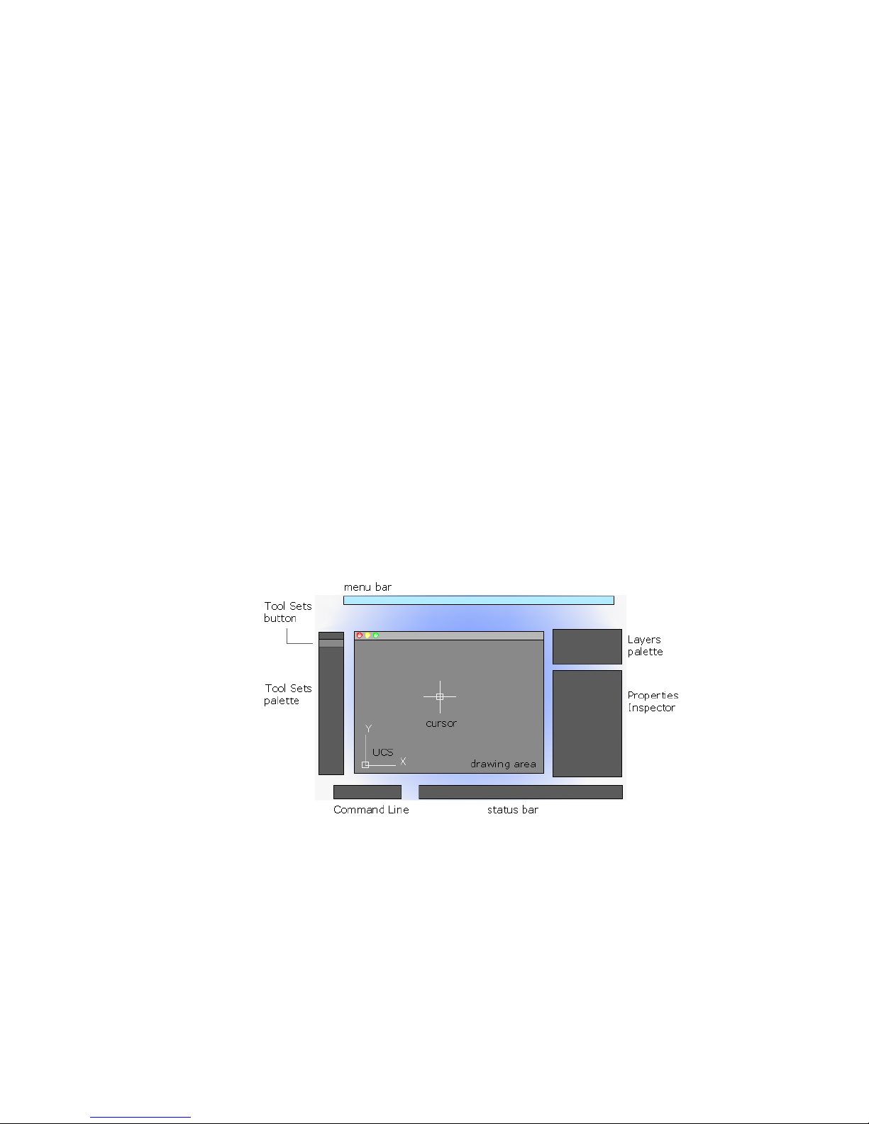
Parts of the User Interface
The user interface consists of palettes and bars around the drawing area. Also,
several controls are displayed within the drawing area.
2
■ Cmd-1 turns the Tool Sets palette on and off
■ Cmd-2 turns the Content Libraries palette on and off
■ Cmd-3 turns the Command Line on and off
7
Page 28
■ Cmd-4 turns the Layers palette on and off
■ Cmd-5 turns the Properties Inspector on and off
■ Cmd-6 turns the Status bar on and off
■ Cmd-7 turns the Reference Manager palette on and off
■ Cmd-0 turns all palettes and bars on and off
You can dock palettes by dragging them to the edge of your screen until a
blue line appears, and then dropping them into place. You can also undock
them by dragging and dropping.
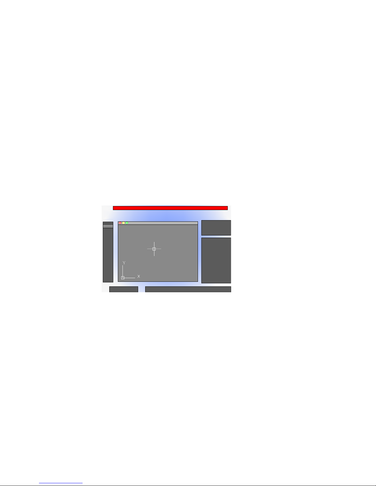
The Menu Bar
The menu bar contains common commands organized into logical categories.
Use the menu bar when learning the product, or browsing for a command.
Many, but not all commands are accessible from the menu bar. Less commonly
used commands can be entered at the Command prompt. All available
commands are listed in the Help system under Command Reference.
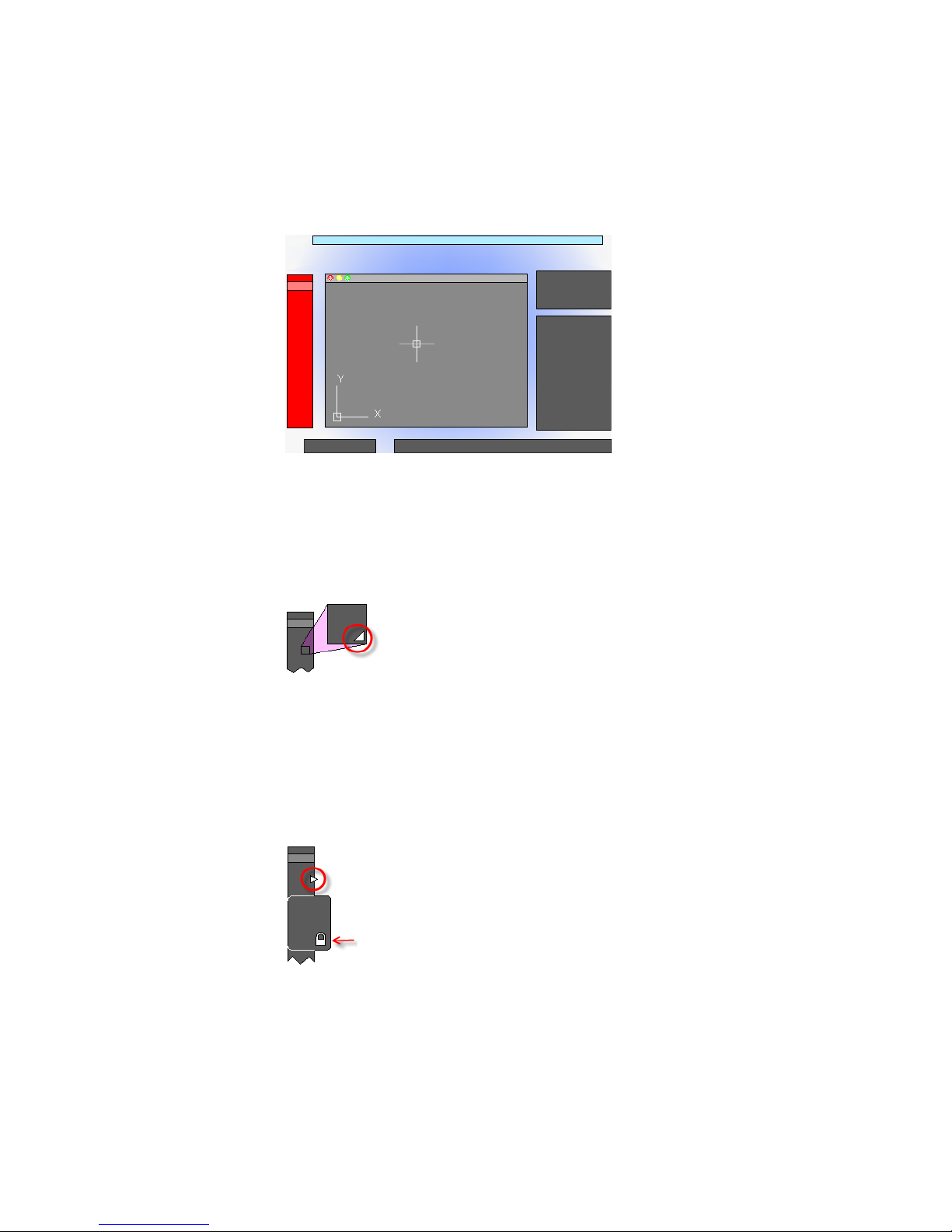
The Tool Sets Palette
The Tool Sets palette provides efficient access to AutoCAD commands.
■ Tool flyouts
■ Tool groups
8 | Chapter 2 The User Interface
Page 29
■ Tool sets
The size of the icons on the Tool Sets palette can be adjusted by using the
Tool Set & Status Bar Icons slider on the Look & Feel tab of the Application
Preferences dialog box (OPTIONS command).
Tool Flyouts
Some of the tools on the Tool Sets palette have a flyout indicator.
Click and hold the flyout to display several options for that command.
Tool Groups
The tools on the Tool Sets palette are organized into tool groups. Click the
arrow to display the entire tool group, which includes additional commands.
To make the tool group stay visible, click the lock icon at the bottom of the
tool group.
Start a Command | 9
Page 30
If you right-click the Tool Sets palette, a menu displays that you can use to
turn off any tool groups that you don’t need.
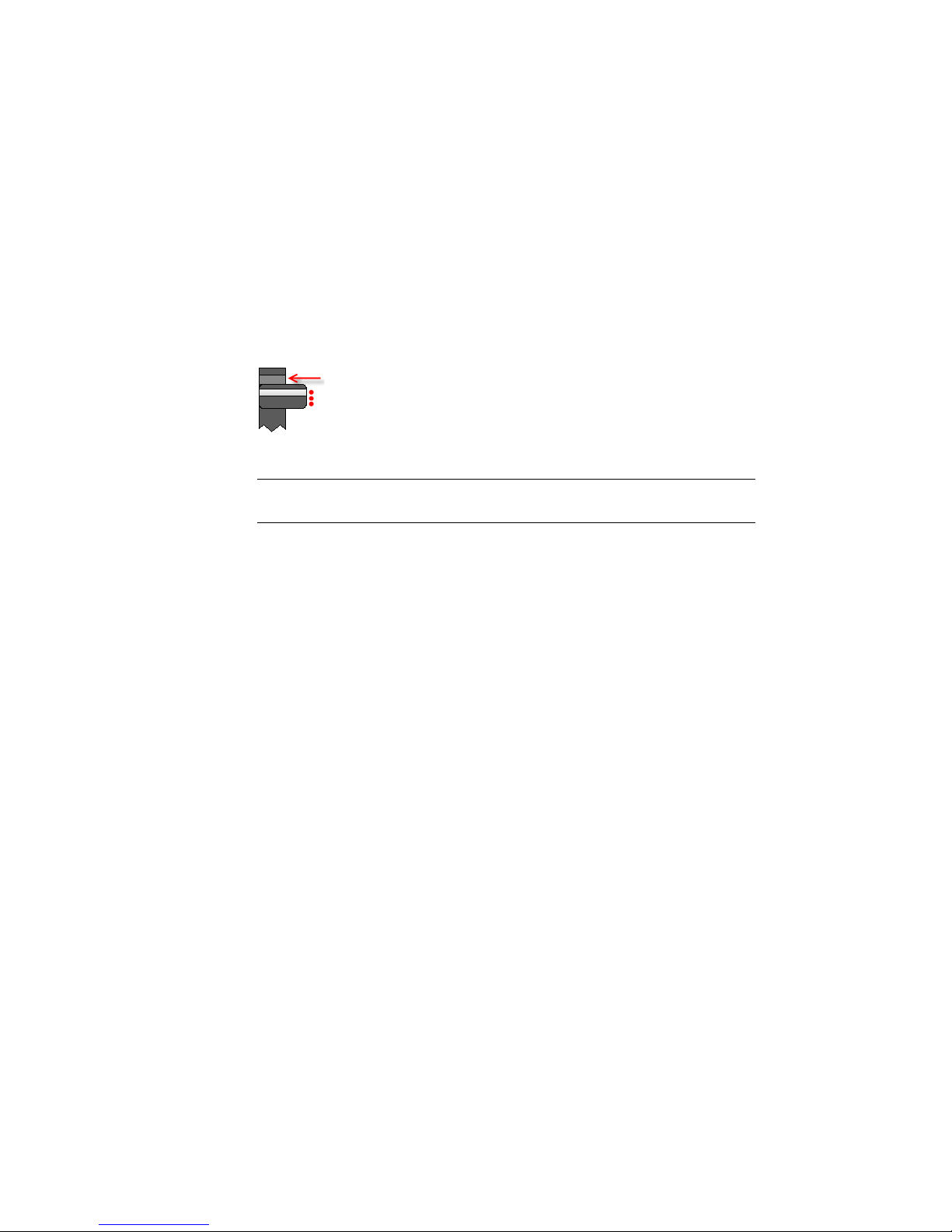
Tool Sets
Click the Tool Sets button to display a list of alternate sets of commands based
on your current tasks. For example, clicking the Annotation tool set replaces
the commands in the Tool Sets palette with commands associated with
dimensioning.
Cmd-1 turns the Tool Sets palette on and off.
TIP Use the Customize dialog box to customize any tool set, or create your own
tool sets.
The Command Line
The Command Line provides a fast way to enter commands and system
variables directly using the keyboard.
Overview of Using the Command Line
The Command Line is not displayed by default, but when initially displayed
it is positioned along the bottom of the screen.
10 | Chapter 2 The User Interface
Page 31

Using the keyboard, you can enter the following in the Command Line:
■ A command or command abbreviation called a command alias
■ The capitalized letters of an option for a command
■ A setting called a system variable that controls how the program operates
by default
Many advanced users prefer this method for speed. Also, the Command Line
displays prompts and error messages.
Cmd-3 turns the Command Line on and off.
Enter Commands on the Command Line
You can enter a command by using the keyboard. Some commands also have
abbreviated names called command aliases.
To enter a command by using the keyboard, type the full command name or
its command alias in the input area of the Command Line, and then press
Enter or Spacebar. The Command Line includes several controls.
Start a Command | 11
Page 32

NOTE When Dynamic Input is turned on and is set to display dynamic prompts,
you can enter commands and options in tooltips near the cursor. Dynamic Input
can be turned on an off from the status bar.
Display Valid Commands and System Variables
By default, AutoCAD automatically completes the name of a command or
system variable as you type it. Additionally, a list of valid choices is displayed
from which you can choose. Use the AUTOCOMPLETE command to control
which automatic features that you want to use.
If the automatic completion feature turned off, you can type a letter on the
command line and press TAB to cycle through all the commands and system
variables that begin with that letter. Press Enter or Spacebar to start the
command or system variable.
Enter Alternate Names of Commands
Some commands also have alternate names. For example, instead of entering
circle to start the CIRCLE command, you can enter c. Command aliases are
defined in the acadlt.pgp file.
To define your own command aliases, see Create Command Aliases in the
Customization Guide.
Specify Command Options
When you enter a command in the Command Line, you see either a set of
options, a dialog box, or a palette. To specify an option displayed in the
Command line, enter the capitalized letters for the option. For example, when
you enter circle, the following prompt is displayed:
Specify center point for circle or [3P/2P/Ttr (tan tan radius)]:
You can specify the center point for the circle either by entering X,Y coordinate
values, or by using the pointing device to click a point in the drawing area.
To choose a different option, enter the letters capitalized in one of the options
in the brackets. You can enter uppercase or lowercase letters. For example, to
choose the three-point option (3P), enter 3p.
Repeat and Cancel Commands
You can repeat the previous command by pressing Enter or Spacebar.
12 | Chapter 2 The User Interface
Page 33

To repeat a recently used command, right-click in the Command Line or click
the drop-down arrow to the left of the command input area. This action
displays a shortcut menu with a list of recently used commands.
You can also repeat a recently used command by cycling through the
commands with Up Arrow and Down Arrow keys, and then pressing Enter.
To cancel any command in progress, press Esc.
See also:
Use Dynamic Input (page 144)
Create Command Aliases
Enter System Variables on the Command Line
System variables are settings that control how certain commands work.
Sometimes you use a system variable in order to change a setting. At other
times you use a system variable to display the current status.
With system variables, you can
■ Turn on or turn off features. For example, the GRIDMODE system variable
turns the grid display on and off when you change the value.
■ Control the operation of a command. For example, the HPASSOC syatem
variable controls whether hatch patterns are associative by default.
■ Retrieve stored information about the current drawing and about the
program configuration. For example, CDATE is a read-only system variable
that stores the current date in decimal format. You can display the values
of read-only system variables, but you cannot change them.
Usually system variables are accessible from dialog boxes. You can change
their values either in a dialog box, directly in the Command Line, or
automatically in a script.
Enter System Variables on the Command Line
To change the setting of a system variable
1 In the Command Line, enter the system variable name. For example,
enter pickadd to change the style for selecting objects, whether selecting
Start a Command | 13
Page 34

objects automatically replaces the current selection set, or whether they
are added to the current selection set.
2 If necessary, press Fn-F1 to view the documentation for that system
variable.
3 Enter the setting that you want to use. In the example of PICKADD,
enter 0, 1, or 2 to determine how you select multiple objects.
Switch Between Dialog Boxes and the Command Line
You can display prompts on the command line instead of using a dialog box,
or switch back again. This option is useful primarily when using scripts.
Some functions are available both in the Command Line and in a dialog box.
In many cases, you can enter a hyphen before a command to suppress the
dialog box and display prompts in the Command Line instead.
For example, entering layer on the command line displays the Layers palette.
Entering -layer on the command line displays the equivalent Command Line
options.
Suppressing a dialog box is useful for familiar operation with earlier versions
of the program, and for using script files. There may be slight differences
between the options in the dialog box and those available in the Command
Line.
These system variables also affect the display of dialog boxes:
■ ATTDIA controls whether the INSERT command uses a dialog box for
entering block attribute values.
■ EXPERT controls whether certain warning dialog boxes are displayed.
■ FILEDIA controls the display of dialog boxes used with commands that
read and write files. For example, if FILEDIA is set to 1, SAVEAS displays
the Save Drawing As dialog box. If FILEDIA is set to 0, SAVEAS displays
prompts on the command line. The procedures in this documentation
assume that FILEDIA is set to 1. Even when FILEDIA is set to 0, you can
display a file dialog box by entering a tilde (~) at the first prompt.
FILEDIA and EXPERT are useful when you use scripts to run commands.
View and Edit Within the Command History
You can copy text from the Command History to repeat commands.
14 | Chapter 2 The User Interface
Page 35
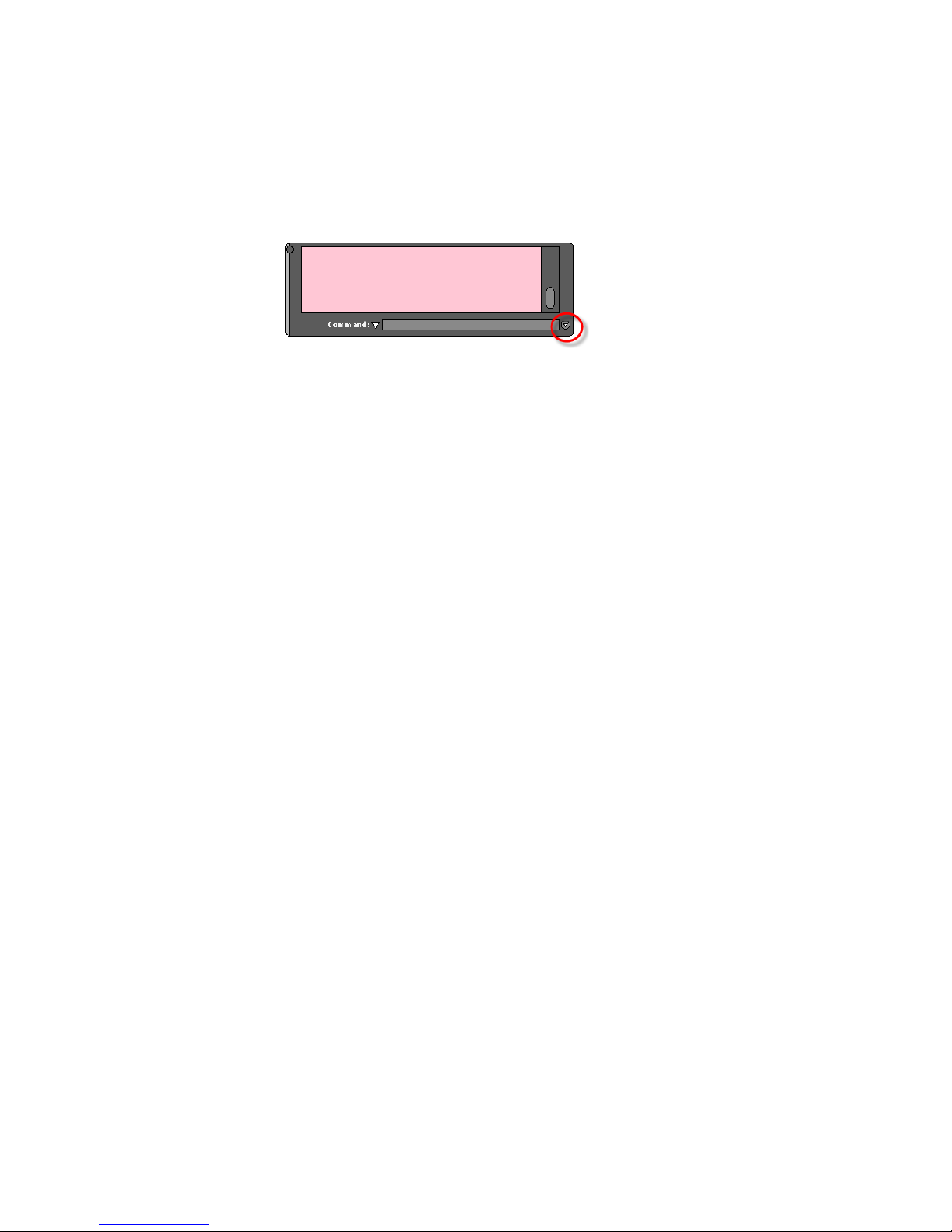
You can expand and collapse the Command History in the Command Line
using the indicated control.
Within the Command History, use the Up Arrow and Down Arrow keys, the
scroll bar, or other scrolling method to locate and then highlight previously
entered commands, system variables, and text.
By default, pressing Cmd-C copies highlighted text to the Clipboard. Pressing
Cmd-V pastes text from the Clipboard to the Command Line.
To copy all the text in the Command History to the Clipboard, right-click and
select Copy History from the shortcut menu, or enter the COPYHIST command.
To save commands automatically to a log file starting with the next command,
enter the LOGFILEON command.
Work with Shortcut Menus
Display a shortcut menu for quick access to commands that are relevant to
your current activity.
Shortcut menus can be used to:
■ Display the controls for a user-interface element such as a palette or the
status bar
■ Control the command in progress, including command options, object
snaps, and canceling
■ Display a list of recent input or repeat the last command entered
■ Cut, copy, and paste from the Clipboard
■ Display a dialog box, such as Drafting Settings or Preferences
■ Undo the last command entered
In the Application Preferences dialog box (the OPTIONS command), you can
customize right-click behavior to be time sensitive, so that a quick right-click
acts the same as pressing Enter, and a longer right-click displays a shortcut
menu.
Start a Command | 15
Page 36

About Keyboard Shortcuts
Keyboard shortcuts allow for quick access to drafting aids, file management
commands, and the Clipboard.
The shortcut keys that AutoCAD LT supports are:
DescriptionKeyboard Shortcut
Fn-F1
Fn-F2
Fn-F5
Cmd-2
Launches the default Web browser and displays the Landing page or a specific Help
topic based on the current context of the
program.
Expands or collapses the display of the
Command Window.
Toggles object snap mode on and off.Fn-F3
Toggles isoplane mode between top, right,
and left isometric planes.
Toggles grid display on and off.Fn-F7 or Control-E
Toggles ortho mode on and off.Fn-F8 or Cmd-L or Shift-Cmd-O
Opens or closes the Tool Sets palette.Cmd-1
Opens or closes the Content palette on and
off.
Shows or hides the Command Window.Cmd-3
Cmd-5 or Cmd-I
16 | Chapter 2 The User Interface
Opens or closes the Layers palette.Cmd-4
Opens or closes the Properties Inspector
palette.
Page 37

DescriptionKeyboard Shortcut
Cmd-6
Cmd-7
Cmd-C or Control-C
Cmd-I
Toggles the display of the status bar on and
off.
Opens or closes the Reference Manager
palette.
Toggles CleanScreen on and off.Cmd-0 or Shift-Cmd-F
Selects all objects in the current layout.Cmd-A or Control-A
Toggles grid snap mode on and off.Cmd-B or Control-B
Copies the selected objects to the Clipboard.
Displays the Find and Replace dialog box.Cmd-F
Groups the selected objects.Cmd-G
Opens or closes the Properties Inspector
palette.
Toggles ortho mode on and off.Cmd-L or Control-L
Cmd-N or Control-N
Cmd-O or Control-O
Cmd-P or Control-P
Minimizes the current drawing window.Cmd-M
Displays the Select Template dialog box.
Select a template to create a new drawing.
Displays the Select File dialog box. Select a
drawing file to open.
Displays the Print dialog box, and creates
a hard copy or PDF file of the current layout.
Closes the program.Cmd-Q or Control-Q
Start a Command | 17
Page 38

DescriptionKeyboard Shortcut
Regenerates the current viewport.Cmd-R
Cmd-S or Control-S
Cmd-V or Control-V
Cmd-X or Control-X
Cmd-,
Saves the current drawing. If the drawing
has not been saved yet, the Save Drawing
As dialog box is displayed.
Toggles polar tracking on and off.Cmd-U or Control-U
Pastes the contents of the Clipboard to the
current layout.
Closes the current drawing.Cmd-W
Removes the selected from the drawing and
adds them to the Clipboard.
Reverses the most recent undo.Cmd-Y or Control-Y
Undoes the most recent action.Cmd-Z or Control-Z
Zooms the drawing out by .5 times.Cmd- -
Zooms the drawing in by 2 times.Cmd- +
Displays the Application Preferences dialog
box.
Shift-Cmd-C
18 | Chapter 2 The User Interface
Displays the Quick View dialog box.Cmd-.
Toggles group selection mode on and off.Shift-Cmd-A
Displays the Color Palette. Select a new
color to make it the current color for new
objects.
Toggles Dynamic Input mode on and off.Shift-Cmd-D
Page 39

DescriptionKeyboard Shortcut
Toggles CleanScreen mode on and off.Shift-Cmd-F
Ungroups the selected group.Shift-Cmd-G
Toggles the display of all palettes on or off.Shift-Cmd-H
Toggles ortho mode on and off.Shift-Cmd-O or Control-L
Displays the Page Setup Manager.Shift-Cmd-P
Shift-Cmd-R
Control-C
Regenerates all viewports in the current
layout.
Displays the Save Drawing As dialog box.Shift-Cmd-S
Toggles object snap tracking on and off.Shift-Cmd-T
Reverses the most recent undo.Shift-Cmd-Z
Displays the Check Spelling dialog box.Shift-Cmd-;
Selects all objects in the current layout.Control-A
Toggles grid snap mode on and off.Control-B
Copies the selected objects to the Clipboard.
Toggles grid display on and off.Control-E
Toggles object snap mode on and off.Control-F
Toggles grid display on and off.Control-G
Toggles PICKSTYLE on and off.Control-H
Start a Command | 19
Page 40

DescriptionKeyboard Shortcut
Toggles the coordinates display mode.Control-I
Repeats the previous command.Control-J
Toggles ortho mode on and off.Control-L
Repeats the previous command.Control-M
Control-N
Control-O
Control-P
Control-S
Control-V
Control-X
Displays the Select Template dialog box.
Select a template to create a new drawing.
Displays the Select File dialog box. Select a
drawing file to open.
Displays the Print dialog box, and creates
a hard copy or PDF file of the current layout.
Closes the program.Control-Q
Saves the current drawing. If the drawing
has not been saved yet, the Save Drawing
As dialog box is displayed.
Toggles polar tracking on and off.Control-U
Pastes the contents of the Clipboard to the
current layout.
Removes the selected from the drawing and
adds them to the Clipboard.
20 | Chapter 2 The User Interface
Reverses the most recent undo.Control-Y
Undoes the most recent action.Control-Z
Page 41

DescriptionKeyboard Shortcut
Control-Arrow Left
Control-Arrow Right
Control-Arrow Up
Control-Arrow Down
Shift-Control-C
Nudges the selected objects to the left in
the drawing area.
Nudges the selected objects to the right in
the drawing area.
Nudges the selected objects up in the
drawing area.
Nudges the selected objects down in the
drawing area.
Toggles group selection mode on and off.Shift-Control-A
Toggles grid snap mode on and off.Shift-Control-B
Copies the selected objects to the Clipboard
with a specified base point.
Toggles object snap mode on and off.Shift-Control-F
Toggles grid display on and off.Shift-Control-G
Delete
Repeats the previous command.Shift-Control-J
Repeats the previous command.Shift-Control-M
Toggles ortho mode on and off.Shift-Control-O
Displays the Save Drawing As dialog box.Shift-Control-S
Toggles polar tracking on and off.Shift-Control-U
Removes the selected objects from the
drawing.
Start a Command | 21
Page 42

Control the Drawing Area Interface
The drawing area includes several tools and controls for viewing and drawing
operations. You can adjust the display of these interface elements.
Interface Themes and Background Color
Many options are provided for customizing the look and feel of the product,
including the color of the icons and the background color of the drawing area.
The default color of the icons and palettes are dark gray. If you prefer, you
can change this theme to a light color.
The default background color of the drawing area is a medium gray, which is
optimum for displaying objects with different colors. Nevertheless, some
people prefer a white or a black background color depending on their tasks
and preferences.
See also:
Set Up the Drawing Area (page 32)
Interface Themes and Background Color
To change the color of the user interface between dark and light
1 On the menu bar, click AutoCAD LT 2013, and then Preferences.
2 In the Application Preferences dialog box, left column, click Look & Feel.
3 Under Interface Theme, click in the Themes box, and click either Dark
or Light.
4 Click OK.
To change the background color of the drawing area in Model space
1 On the menu bar, click AutoCAD LT 2013, and then Preferences.
2 In the Application Preferences dialog box, left column, click Look & Feel.
3 Under Interface Theme, click in the Model box, and then click a color,
or click Select Color.
The default dark gray background color has an RGB value of 33,40,48.
22 | Chapter 2 The User Interface
Page 43

4 If you clicked Select Color, the Color Palette dialog box is displayed. At
the top of the dialog box, click either Index Color, True Color, or Color
Books, and then make your color selection. Click OK to exit the Color
Palette dialog box.
5 Click OK.
Cursors in the Drawing Area
In the drawing area, the appearance of the cursor changes depending on what
you are doing.
■ If you are prompted to specify a point location, the cursor appears as
crosshairs
■ If you are prompted to select an object, the cursor changes to a small square
called a pickbox
■ When you are not in a command, the cursor appears as a combination of
the crosshairs and pickbox cursors
■ If you are prompted to enter text, the cursor appears as a vertical bar
In the following illustrations, these cursors are displayed in order.
You can change the size of the crosshairs and pickbox cursors in the
Application Preferences dialog box by clicking Cursor & Selection (the
OPTIONS command).
Selection Style
Selecting objects conforms to a selection style that is common to most Mac
applications.
Use click and drag to specify a rectangular selection area. Drag to the left for
a crossing selection, or drag to the right for a window selection.
Each time you select one or more objects, it automatically clears the previous
selection. To add objects to the previous selection, hold Shift as you select
them.
Control the Drawing Area Interface | 23
Page 44

You can change the behavior of object selection in the Application Preferences
dialog box by clicking Cursor & Selection (the OPTIONS command).
See also:
Select Multiple Objects (page 196)
The UCS Icon
The drawing area displays an icon representing the XY axis of a rectangular
coordinate system called the User Coordinate System, or UCS.
You can move or rotate the UCS icon with the UCS command, or by clicking
and dragging the icon using the grips that are displayed. The UCS is useful
because it controls features that include
■ The angular orientation that defines horizontal and vertical
■ The alignment and angle of the grid, and hatch patterns
■ The origin and orientation for 2D and 3D coordinate entry
You can change the appearance of the UCS icon with the UCSICON command,
Properties option. With this command, you can also control whether the UCS
icon is visible.
See also:
Overview of the User Coordinate System (UCS) (page 130)
Control the Display of the User Coordinate System Icon (page 132)
24 | Chapter 2 The User Interface
Page 45

The Coordinates Display
The coordinates display is located in the lower-right corner of the active
viewport and displays the current location of the crosshair cursor in the
drawing area.
The display of the coordinates in the active viewport can be toggled in the
Units & Guides tab (Application Preferences dialog box).
Along with the coordinates displayed in the active viewport, you can also get
the current location of the crosshair cursor in a tooltip near the cursor when
dynamic input is turned on. For more information about dynamic input, see
Use Dynamic Input (page 144).
See also:
Use Dynamic Input (page 144)
Overview of Coordinate Entry
Model Space and Layouts
There are two working environments, or spaces, in which you can work, model
space and paper space layouts.
■ Model space is used to create 2D drawings
■ Paper space is used create layouts for plotting
While you can plot from model space, layouts are more convenient for scaling
views, changing the location of views, and controlling the area and settings
used in plotting.
To switch between model space and a layout, click the drop-down near the
left side of the status bar.
Control the Drawing Area Interface | 25
Page 46

See also:
Quick Start for Layouts (page 71)
Control Status, Layers, Properties, and Content
Use the Status bar, Layers palette, Properties Inspector, and Content palette
to change which drafting aids are enabled, modify the layers in the current
drawing, the properties of the current drawing or selected objects, and insert
blocks or hatch patterns from custom content libraries.
The Status Bar
The Status bar includes buttons that turn on and off various features.
For example, this is where you can conveniently turn on and off the grid
display, grid snap, object snap, dynamic input, and so on. The status bar also
includes controls to display lineweights and object transparency. Several
controls relate to the annotation scaling feature.
26 | Chapter 2 The User Interface
Page 47

One of the most important controls on the status bar, highlighted in the
illustration, changes the drawing area between model space and paper space
layouts.
The size of the icons and controls on the status bar can be adjusted by using
the Tool Set & Status Bar Icons slider on the Look & Feel tab of the Application
Preferences dialog box (OPTIONS command).
Cmd-6 turns the status bar on and off.
The Status Bar
To control the display of buttons on the status bar
1 Right-click any empty area of the status bar.
2 In the status bar menu, click Display, and then any flyout.
3 Click any button name in the flyout to change whether it is displayed
or hidden.
The Layers Palette
The Layers palette is used to display and manage layers and layer groups.
The disclosure triangle in the Layers palette expands and compresses the Layers
palette to display either
■ All layers and layer groups in a matrix of information, or
■ The current layer only
Control Status, Layers, Properties, and Content | 27
Page 48

Cmd-4 turns the Layers palette on and off.
Display All Layers and Layer Properties
The layers and layer properties in a drawing can be displayed as a matrix,
similar to a spreadsheet. Each row contains a layer and each column represents
a layer property. Right-click the column header in the Layers list to control
which layer properties are displayed.
When undocked in this format, the Layers palette can display all layer
information simultaneously at the cost of taking up space on the screen.
Docking the Layers palette reduces the space it takes up, but you might have
to scroll left and right to see all the properties.
Display the Current Layer Only
Under normal working conditions, the compressed format that displays only
the name of the current layer is adequate and recommended.
Review Layer Properties
The Properties Inspector palette can be used to display all the properties of
either the current layer, or a selected layer as a vertical list. To switch from
displaying object properties, click the Layer Properties tab at the top of the
Properties Inspector palette.
Display Layer Groups
Layer groups are displayed in the Layer list and allow you to group layers
together by what they represent in the drawing or similar layer properties.
Grouping layers together allows you to change the layer status of all the layers
in the group, and to access the current state or function of layers in the drawing
through the use of dynamic layer groups. Dynamic layer groups automatically
maintain a listing of all the layers that meet a specific set of rules or criteria.
There are four automatic dynamic layer groups that the Layer list supports
and they are:
■ All Used Layers. Lists all the layers that are currently being used in the
drawing.
■ Xref. Lists all the attached external references (xrefs) as nested layer groups,
and each layer group contains the layers of the corresponding xref.
■ Viewport Overrides. Lists all the layers that have viewport overrides
assigned to them in the current viewport.
28 | Chapter 2 The User Interface
Page 49

■ Unreconciled Layers. Lists all the layers that have been recently added
to the drawing and need to be reconciled.
Use Display Settings in the lower-right corner of the Layers palette to control
the display of layer groups in the Layer list. You can also determine which
automatic dynamic layer groups should be displayed and where in the Layer
list that layer groups should be listed.
See also:
Work with Layers (page 101)
The Layers Palette
To create a new layer
1 If necessary, click the Show Layer List disclosure triangle to expand the
Layers palette.
2 At the bottom-left corner of the palette, click the Create Layer button
which looks like a stack of papers.
3 Enter the name of the new layer in the highlighted text area, and then
press Enter.
To change the current layer
1 On the Layers palette, click the Layer drop-down.
2 Click the layer that you want to make the current layer.
There are several alternative methods. In the expanded Layers palette, you
can right-click a layer to display a menu, or you can double-click on the layer
name.
To filter the list of layers
1 If necessary, click the disclosure triangle to expand the Layers palette.
2 Enter one of more characters in the Search area at the bottom of the
palette.
Only the layers with the characters that you entered are displayed in the
Layers palette. Wildcards are not available.
Control Status, Layers, Properties, and Content | 29
Page 50
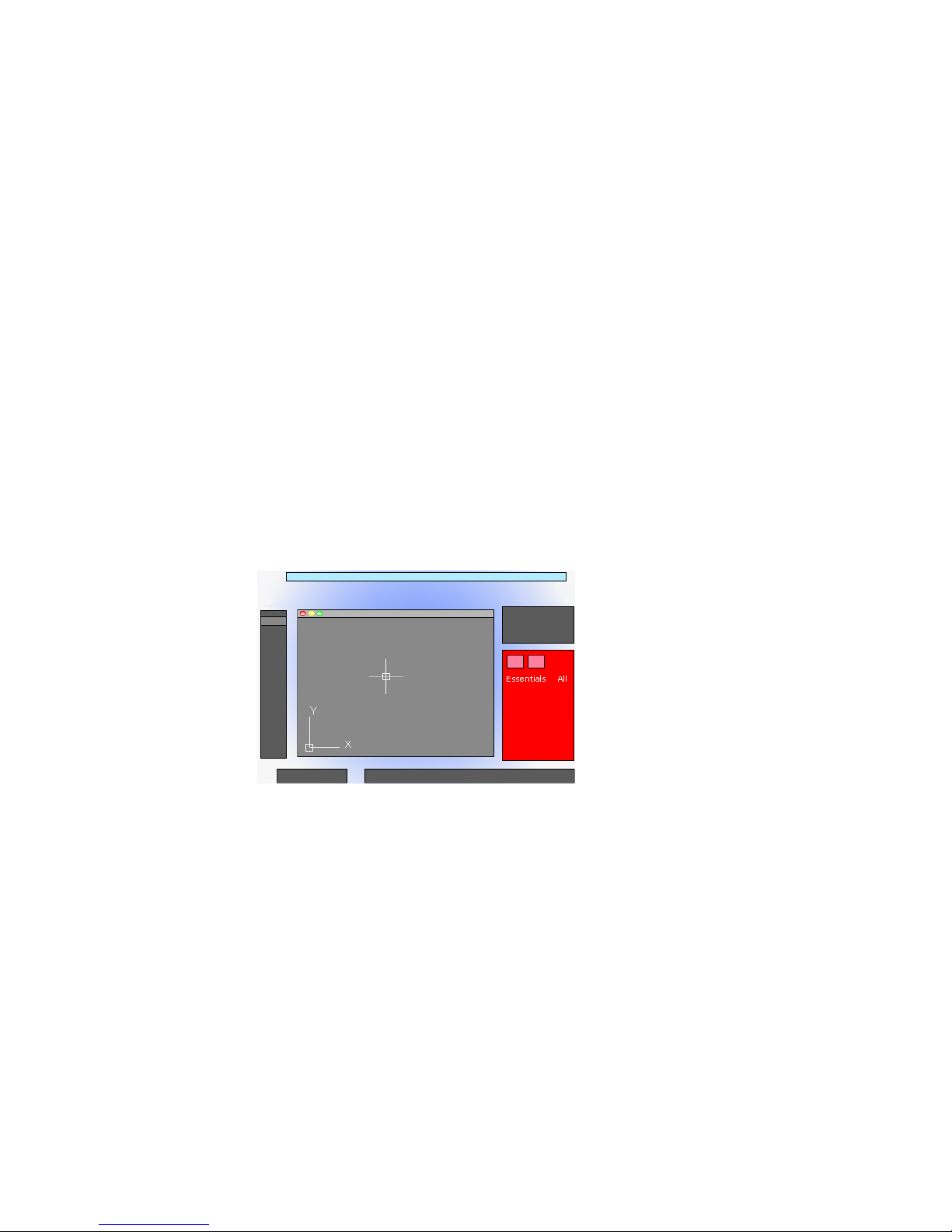
3 It is recommended that you delete the text in the Search area when you
are done.
You can click the magnifying glass icon to display and choose from a
list of previous searches.
The Properties Inspector
With the Properties Inspector, you can display and change the settings and
properties for objects and for layers.
You can perform the following actions:
■ Specify the current default properties assigned to all new objects
■ View and change the properties of one or more selected objects
■ Specify the default properties of the current layer
The key to controlling the information that appears in the Properties Inspector
is choosing either the Object/Current tab, or the Layer Properties tab in the
top-left corner of the palette.
For object properties, clicking either the Essentials button or the All button
controls the number of properties displayed.
Object/Current Properties Tab
The Properties Inspector with the Object/Current button clicked can complete
one of three actions depending on what is selected.
■ With no objects selected, it displays the default properties to be used for
all new objects. You can change these defaults by clicking a property in
the palette, and specifying a different value.
30 | Chapter 2 The User Interface
Page 51

■ With one object selected, it displays the properties for that object only,
and you can change any of its properties.
■ With more than one object selected, it can either display only the common
properties shared by the objects, or all the properties. Any property that
you change is applied to all the selected objects.
Layer Properties Tab
The Properties Inspector provides an efficient way of displaying the properties
and settings associated with the current layer, or a layer that you select in the
Layers palette.
Cmd-5 turns the Properties Inspector on and off.
See also:
Overview of Object Properties (page 99)
The Content Palette
The Content palette allows you to access and manage content libraries.
From the Content palette you can
■ Create custom content libraries to organize frequently used blocks
■ Add and remove blocks from the Favorites library or a custom library
■ Insert blocks from the current drawing, Favorites library, or a custom library
Content Libraries
Libraries are used to help organize and access the blocks that you frequently
use. By default, there is no content available in the Content palette. Custom
libraries are created and managed using the Manage Content Libraries dialog
box. You add content to a library by referencing a saved DWG or DXF file, or
block contained in a saved DWG file.
After content has been added to a library, you can
■ Insert a block into a drawing (see -INSERT)
■ Add a block to or remove it from the Favorites library
■ Search for a block in a library
Control Status, Layers, Properties, and Content | 31
Page 52

WARNING If a drawing being referenced by Favorites or a custom library is moved,
the reference is maintained but the associated block cannot be inserted into a
drawing.
See also:
Insert Blocks (page 271)
Customize the Drawing Environment
Many elements of the working environment can be customized to fit your
needs.
You can change many window and drawing environment settings in the
Application Preferences dialog box. For example, you can change how often
a drawing is automatically saved to a temporary file, and you can link the
program to folders containing files you use frequently.
Set Interface Options
You can adjust the application interface and drawing area to match the way
you work.
Set Up the Drawing Area
You can adjust the color and display schemes used in the application and
drawing windows, and control the behavior of general features such as grip
editing behavior.
Many of the settings are available from shortcut menus and the Application
Preferences dialog box.
Some user interface elements, such as the presence and location of menu items
and palettes, can be specified and saved using the Customize dialog box.
Some settings affect how you work in the drawing area:
■ Color Scheme (Application Preferences dialog box, Look & Feel
tab). You specify a dark or light color theme for the overall user interface.
The settings affect the window frame background, status bar, title bar, and
palettes.
32 | Chapter 2 The User Interface
Page 53

■ Background Colors (Application Preferences dialog box, Look
& Feel tab). You specify the background colors used in the Model and
named layouts.
■ UCS Icon Style, Size, and Color (UCS Icon dialog box). You can
control the appearance of the UCS icon in model space and paper space.
■ Clean Screen. You can expand the drawing area to display only the menu
bar with the Clean Screen button on the status bar. Press Ctrl-0 to restore
the previous setup.
Tooltips
Several types of tooltips provide pop-up information for interaction with
toolbars, object snaps, and drafting operations.
Tooltips are displayed for tools on the Tool Sets and other palettes in the user
interface. Hover the cursor over the control to display the tooltip.
See also:
User Interface Customization in the Customization Guide
Specify the Behavior of Palettes
Palettes, such as Tool Set, status bar, and Reference Manager can be docked,
displayed as icons, or floated.
Settings for these and other options are often changed on a shortcut menu,
available by right-clicking the title bar of the palette.
■ Resize. Drag an edge of the palette to change its size. If one or more
palettes are docked, dragging one of the palettes adjusts the size of the
other docked palettes.
■ Collapse to Icons. You can collapse the display of all palettes, except
command line and status bar, to a set of icons that are displayed along the
left or right side of the screen. Click an icon to temporarily display the
associated palette. (PALETTEICONON command)
■ Show as Palettes. Expands all palettes that are currently collapsed as
icons. The palettes are returned to their previous size and location.
(PALETTEICONOFF command)
You can hide all the palettes at once with HIDEPALETTES and turn on all
hidden palettes with SHOWPALETTES.
Customize the Drawing Environment | 33
Page 54

NOTE
If a palette has been turned back on manually and moved, it is not affected
by SHOWPALETTES.
The placement of palettes can be changed by dragging them on screen. You
can control the location a palette is docked by dragging it to the edge of the
screen and dropping it when you see a blue bar. You can also drag and drop
palettes on a palette that is already docked.
Use RESETPALETTES to return all palettes to their default placement.
Performance Tuning
Performance tuning examines your graphics card and display driver and
determines whether to use software or hardware implementation for features
that support both.
Features that cannot work properly on your system are turned off. Some
features may work but not be recommended for use with your graphics card
or 3D graphics display driver. Enable these features at your own risk. For
information on the options available, see -3DCONFIG.
Graphics Caching
Graphics cache files are created and maintained to optimize performance and
increase the regeneration speed of objects with complex geometry such as 3D
solids, non-mesh surfaces, and regions. These cache files persist between
drawing sessions and are saved in /Users/<user name>/Library/Application
Support/Autodesk/local/<product name>/<release>/<language>/GraphicsCache. The
maximum number of these cache files are limited in number and total size
by the CACHEMAXFILES and CACHEMAXTOTALSIZE system variables. If the
limits are exceeded, the oldest cache files are automatically deleted.
NOTE If you ever need to delete the graphics cache files, you can temporarily set
CACHEMAXFILES or CACHEMAXTOTALSIZE to 0.
Customize Startup
Command line switches can be used to control how the program is started
from the Terminal window or a shell script.
34 | Chapter 2 The User Interface
Page 55
You can use command line switches to specify several options when you start
the program. For example, you can run a script or start with a specified drawing
template.
Command line switches are parameters you can use to create custom shell
scripts to start AutoCAD LT in a specific way. Valid switches are listed in the
following table.
Script name-b
Template file name-t
Designates a script to run after you start the
program (b stands for batch process). Scripts
can be used to set up drawing parameters
in a new drawing file.
Creates a new drawing based on a template
or prototype drawing.
The syntax for using command line switches is
pathname/AutoCAD LT [drawingname] [-switchname]
When using a switch option, you must follow the switch with a space and
then the name of a file. For example, the following entry starts the program
from a folder named AutoCAD LT 2013with the drawing template arch1.dwt
and executes a script file startup.scr.
/Applications/Autodesk/AutoCAD LT 2013/AutoCAD LT
2013.app/Contents/MacOS/AutoCAD LT -t /templates/arch1.dwt
-b startup.scr
Customize the Drawing Environment | 35
Page 56

36
Page 57

Start and Save Drawings
Start a Drawing
All drawings start from either a default drawing template file or a custom drawing
template file that you create. Drawing template files store default settings, styles,
and additional data.
Overview of Starting a New Drawing
Before you start to draw, you need to decide what system of drawing units that
you will use in the drawing, and then choose a drawing template file appropriate
for those drawing units.
Choose Drawing Units
3
A drawing unit can equal one inch, one millimeter, or any other system of
measurement. For more information about drawing units, see Determine the
Units of Measurement (page 38).
Choose a Drawing Template File
When you start a new drawing, AutoCAD LT accesses a drawing template file
to determine many default settings such as unit precision, dimension styles,
layer names, a title block, and other settings. Many of the settings are based on
whether the drawing template file is intended for use with a drawing created
in inches, feet, millimeters, centimeters, or other unit of measurement.
37
Page 58

Customize a Drawing Template File
By customizing your own drawing template file, you save yourself a lot of
work changing settings, and you also ensure that the settings are standardized.
You can create several drawing template files for different projects, and you
can choose one when you click New.
Specify Units and Unit Formats
Before you start to draw, you decide on the units of measurement to be used
in the drawing, and set the format, precision, and other conventions to be
used in coordinates and distances.
Determine the Units of Measurement
Before you start to draw, you must decide what one drawing unit represents
based on what you plan to draw. You can convert a drawing between systems
of measurement by scaling it.
Every object you create is measured in drawing units. Before you start to draw,
you must decide what one drawing unit will represent based on what you
plan to draw. Then you create your drawing at actual size with that convention.
For example, the objects in the illustration might represent two buildings that
are each 125 feet long, or a section of a mechanical part that is measured in
millimeters.
Convert Drawing Units
If you start a drawing in one system of measurement (imperial or metric) and
then want to switch to the other system, use SCALE to scale the model
geometry by the appropriate conversion factor to obtain correct distances and
dimensions.
38 | Chapter 3 Start and Save Drawings
Page 59

For example, to convert a drawing created in inches to centimeters, you scale
the model geometry by a factor of 2.54. To convert from centimeters to inches,
the scale factor is 1/2.54 or about 0.3937.
See also:
Set the Scale for Dimensions (page 397)
Set the Unit Format Conventions
You can set the format and the number of decimal places to be used when
you enter and display linear and angular units.
Set Linear Units
You can choose from several common conventions to represent the format
and the precision of linear distances and coordinates displayed in the Properties
Inspector palette, dynamic input, the status bar, and other locations.
For example, here are three variations of dynamic input.
Set Angular Units
You can specify that positive values of angles are measured either clockwise
or counterclockwise, and the direction of angle 0 (usually East or North). You
can enter angles using grads, radians, or surveyor's units or using degrees,
minutes, and seconds.
If you use surveyor's angles when specifying polar coordinates, indicate whether
the surveyor's angles are in the north, south, east, or west direction. For
example, to enter the relative coordinates for a property line that is 72 feet,
8 inches long with a bearing of 45 degrees north, 20 minutes, 6 seconds east,
enter @72'8"<n45d20'6"e.
Start a Drawing | 39
Page 60

Understand Rounding and Precision
When you specify the display precision of units, the values for coordinates
and distances are rounded off. However, the internal precision of coordinates
and distances is always maintained regardless of the display precision.
For example, if you set the display precision of decimal-format units to 1 (or
0.0), the display of coordinates is rounded to one place after the decimal point.
Thus, the coordinates 0.000,1.375 are displayed as 0.0,1.4, but the internal
precision is still maintained.
Use a Drawing Template File
A drawing template file provides consistency in the drawings that you create
by maintaining your standard styles and settings.
Select a Drawing Template File
A set of drawing template files is installed with AutoCAD LT. Many of them
are provided either for imperial or for metric units, and some are optimized
for 3D modeling. All drawing template files have a .dwt file extension.
While these drawing templates provide a quick way to start a new drawing,
it is best to create drawing templates specific to your company and the type
of drawings you create.
Create a Drawing Template File
When you need to create several drawings that use the same conventions and
default settings, you can save time by creating or customizing a drawing
template file instead of specifying the conventions and default settings each
time you start. Conventions and settings commonly stored in template files
include
■ Unit format and precision (page 38)
■ Title blocks and borders (page 271)
■ Layer names (page 102)
■ Snap and Grid spacing (page 151)
■ Text styles (page 353)
■ Dimension styles (page 379)
■ Multileader styles (page 347)
40 | Chapter 3 Start and Save Drawings
Page 61

■ Linetypes (page 119)
■ Lineweights (page 123)
■ Layouts (page 71)
■ Page setups (page 431)
By default, drawing template files are stored in the template folder, where they
are easily accessible. You can use the Application Preferences dialog box to
set a default for both the template folder and the drawing template file.
Add Identifying Information to Drawings
You can keep track of your drawings more easily if you add keywords or other
information to them.
Use Finder
Finder can be used to location drawing files. For example, you can search for
all files created on a certain date, or for files you modified yesterday.
Display Properties in Fields
You can assign any of the drawing properties to a field in a text object. For
more information about fields, see Use Fields in Text (page 350).
Open or Save a Drawing
You can use several methods to find and open drawings, even damaged
drawings. You can save and backup drawings automatically.
Open a Drawing
You open drawings to work on them just as you do with other applications.
In addition, you can choose from several alternative methods.
To open a drawing, you can
■ Use Open on the File menu to display the Select File dialog box. If the
FILEDIA system variable is set to 0, the Command prompt version displays
instead of a file navigation dialog box.
Open or Save a Drawing | 41
Page 62

■ Double-click a drawing in Finder to launch AutoCAD LT
®
and open the
drawing. If the program is already running, the drawing opens in the
current session.
■ Drag a drawing from Finder onto the AutoCAD LT icon in the Dock.
If you drop a drawing anywhere outside the drawing area—for example,
the command line or the blank space next to the toolbars— the drawing
is opened. However, if you drag a single drawing into the drawing area of
an open drawing, the new drawing is not opened but inserted as a block
reference.
■ Use the Project Manager to locate and open the drawings in a project data
(DST) file.
Work on Drawings During Loading
You can work on drawings before they are fully open. This is useful when you
work on large drawings and you want to begin working immediately. To take
advantage of this capability, three conditions are required.
■ The drawing must have been saved in paper space.
■ The INDEXCTL system variable must be set to a non-zero value.
When these conditions are met, you can create or modify visible objects, pan
or zoom, turn off or freeze layers, and any other operation that does not require
displaying objects not visible when the drawing was last saved.
NOTE
The Quick View feature will not be fully functional during loading under these
conditions.
Resolve Missing References
As you open a drawing, you are notified (messages and task dialog boxes)
when a reference cannot be located. From the References - Unresolved
Reference Files task dialog box, click Update the Location of the Referenced
Files to open the Reference Manager palette to make changes to missing
external references.
42 | Chapter 3 Start and Save Drawings
Page 63

The following table outlines some of the references that might be missing and
describes how to handle them.
DescriptionMissing Reference Types
External references
Shapes
Missing external references are the result of AutoCAD LT
not being able to resolve the last known location of an
xref, raster image, or underlay. To resolve a missing external reference, locate the file and update its location
using the Reference Manager palette.
For information about resolving missing referenced files,
see
■ Resolve Missing External References (page 472)
■ Attach Raster Image Files (page 491)
■ Attach Files as Underlays (page 481)
Missing shape files are often the result of custom shapes
being used in a linetype. Browse to the missing linetype
file, or place the shape file in the folder with the drawing
or one of the support paths defined in the Application
Preferences dialog box.
Work with Large Objects
AutoCAD LT 2010 supports object size limits greater than those available in
previous releases. With increased object size limits you can create larger and
more complex models. Using increased object size limits can result in
compatibility issues with legacy drawing file formats (AutoCAD LT 2007 and
earlier).
When working with drawings that you might need to exchange with others
using AutoCAD LT 2009 and earlier, set the LARGEOBJECTSUPPORT system
variable to 0. Setting LARGEOBJECTSUPPORT to 0 warns you when a drawing
contains large objects that cannot be opened by a release of the program prior
to AutoCAD LT 2010.
Recover Defective Drawing Files
In some circumstances, it is possible that a drawing file becomes defective.
This can result from hardware problems or transmission errors. If a drawing
Open or Save a Drawing | 43
Page 64

file is corrupt, you might be able to recover it. See Repair, Restore, or Recover
Drawing Files (page 50).
Change the Default Drawing Folder
Each time you start AutoCAD LT, the Documents folder is the default path in
each standard file selection dialog box.
Alternatively, you can start AutoCAD LT in the current folder from the
Terminal window. Set REMEMBERFOLDERS to 0 and then start AutoCAD LT
from the current folder.
See also:
Work with Layouts in a Project (page 84)
Open and Save Drawing Files from the Internet (page 516)
Work with Multiple Open Drawings
You can preview and switch between open drawings and layouts in a drawing
and transfer information between open drawings.
Preview Open Drawings and Layouts
With QuickView, you can easily preview and switch between open drawings
and layouts in an open drawing.
The Show Drawings & Layouts button on the status bar allows you to do the
following:
■ Open drawings. All open drawings are displayed along the left side of
the QuickView dialog box. Double-click a drawing thumbnail to switch to
the corresponding drawing file, or right-click a drawing thumbnail to
display a list of available options. For more information, see Switch Between
Open Drawings (page 45)
■ Layouts in an open drawing. Displays the Model layout and named
layouts in the current drawing or the selected drawing when there is more
than one drawing open. Double-click a layout thumbnail to switch to the
corresponding layout and drawing file, or right-click a layout thumbnail
to display a list of available options. For more information, see Switch
Between Layouts in the Current Drawing (page 45)
44 | Chapter 3 Start and Save Drawings
Page 65

Switch Between Open Drawings
Switch between open drawings.
You can use one of the following methods to switch between open drawings:
■ On the menu bar, click the Window menu and choose a drawing from the
bottom of the menu.
■ In the Mac OS Dock, right-click the AutoCAD LT icon and choose a drawing
from the top of the menu.
■ In the Mac OS Dock, right side, click the thumbnail that represents the
open drawing.
■ On the status bar, click the Show Drawings & Layouts button. In the
QuickView dialog box, click the drawing thumbnail along the left side.
■ On the status bar, click the Drawings & Layouts pop-up menu and choose
a drawing from the top of the menu.
Switch Between Layouts in the Current Drawing
Switch between the model space and layouts in the current drawing.
You can use one of the following methods to switch between layouts in the
current drawing:
■ On the status bar, click the Show Drawings & Layouts button. In the
QuickView dialog box, click the layout thumbnail on the right side.
■ On the status bar, click the Drawings & Layouts pop-up menu and choose
a layout from the middle section of the menu.
■ At the Command prompt, enter ctab and press Enter. When prompted
for a new value, enter model or the name of a layout in the drawing and
press Enter.
Transfer Information between Open Drawings
You can easily transfer information between drawings that are open in a single
session.
When you open multiple drawings in a single session, you can
■ Reference other drawings.
■ Insert blocks between open drawings (CONTENT) command.
Open or Save a Drawing | 45
Page 66

■ Copy and paste between drawings.
■ Use object snaps and the Copy with Basepoint (COPYBASE) command to
ensure accurate placement.
Save a Drawing
You save drawing files for later use just as you do with other applications. You
can also set up automatic saving and backup files and save only selected
objects.
When you work on a drawing, you should save it frequently. Saving protects
you from losing work in the event of a power failure or other unexpected
event. If you want to create a new version of a drawing without affecting the
original drawing, you can save it under another name.
The file extension for drawing files is .dwg, and unless you change the default
file format in which drawings are saved, drawings are saved in the latest
drawing file format. This format is optimized for file compression and for use
on a network.
The character limit for a DWG file name (including its path) is 256 characters.
NOTE If the FILEDIA system variable is set to 0, the Command prompt version
displays instead of a file navigation dialog box.
Save Part of a Drawing File
If you want to create a new drawing file from part of an existing drawing, you
use the WBLOCK command. With the command, you can select objects or
specify a block definition in your current drawing and save them to a new
drawing file. You can also save a description with the new drawing.
Save to a Different Type of Drawing File
You can save a drawing to an earlier version of the drawing format (DWG) or
drawing interchange format (DXF), or save a drawing as a template file. Choose
the format in the Save Drawing As dialog box.
Save with Visual Fidelity for Annotative Objects
When working with annotative objects, this option allows you to maintain
visual fidelity for these objects when they are viewed in AutoCAD LT 2007
46 | Chapter 3 Start and Save Drawings
Page 67

and earlier releases. Visual fidelity is controlled by the SAVEFIDELITY system
variable.
If you work primarily in model space, it is recommended that you turn off
visual fidelity (set SAVEFIDELITY to 0). However, if you need to exchange
drawings with other users, and layout fidelity is most important, then visual
fidelity should be turned on (set SAVEFIDELITY to 1).
NOTE
The SAVEFIDELITY system variable does not effect saving a drawing to the
AutoCAD LT 2010 drawing or DXF file formats.
Annotative objects may have multiple scale representation. When visual
fidelity is on, annotative objects are decomposed and scale representations
are saved (in an anonymous block) to separate layers, which are named based
on their original layer and appended with a number. If you explode the block
in AutoCAD LT 2007 or earlier releases, and then open the drawing in AutoCAD
LT 2008 or later releases, each scale representation becomes a separate
annotative object, each with one annotation scale. It is not recommended
that you edit or create objects on these layers when working with a drawing
created in AutoCAD LT 2008 and later releases in AutoCAD LT 2007 and earlier
releases.
When this option is not selected, a single model space representation is
displayed on the Model layout. More annotation objects may be displayed on
the Model layout depending on the ANNOALLVISIBLE setting. Also, more
objects may be displayed in paper space viewports at different sizes than in
AutoCAD LT 2008 and later releases.
Reduce the Time Required to Save a Drawing File
You can reduce the time required to save a drawing file if you specify
incremental saves rather than full saves. An incremental save updates only
those portions of the saved drawing file that you changed.
When you use incremental saves, drawing files will contain a percentage of
potentially wasted space. This percentage increases after each incremental
save until it reaches a specified maximum, at which time a full save is
performed instead. You can set the incremental save percentage in the Open
and Save tab of the Options dialog box or by setting the value of the system
variable ISAVEPERCENT. If you set the value of ISAVEPERCENT to 0, all saves
are full saves.
To reduce the size of drawing files, it is recommended that you perform a full
save (with ISAVEPERCENT set to 0) before transmitting or archiving a drawing.
Open or Save a Drawing | 47
Page 68

Work Internationally
If you share drawing files with companies in other countries and regions, the
drawing file names might contain characters that are not used in other
languages.
If a drawing file is created in a different language version of the operating
system, the following will occur:
■ If support for the language is installed, the file name characters are visible
in Finder.
■ If support for the language is not installed, the file name characters appear
as a series of boxes in Finder.
In either case, you will be able to open the drawing file beginning with
AutoCAD LT 2007 because the product is Unicode-compliant.
NOTE
If you share drawing files with companies using earlier releases of the product,
you can avoid file name issues for Asian languages and languages that use
accented characters. In those circumstances, do not use high ASCII values, or
values of 80 hexadecimal and above, when creating a file name.
Maintain Compatibility with Large Object Limits
Drawings saved to a legacy drawing file format (AutoCAD LT 2007 or earlier)
do not support objects greater than 256MB. With the AutoCAD LT 2010
drawing file format, these limitations have been removed allowing you to
save objects that are greater in size.
When saving to a legacy drawing file format (AutoCAD LT 2007 or earlier),
the drawing cannot contain large objects; there might be compatibility issues
with trying to open the drawing. The LARGEOBJECTSUPPORT system variable
controls the large object size limits used and the warning messages displayed
when a drawing is saved.
The following explains how object size limits for drawings is determined:
■ Drawing files cannot exceed an internal size limit of 4GB. This size is based
on the total size of all objects in a drawing when uncompressed. Since a
drawing file is normally compressed, the final size of a saved drawing file
on disk will vary based on the size and number of objects in a drawing.
■ Each individual object in a drawing cannot exceed an uncompressed size
limit of 256MB. For example, a mesh object, when saved to a file and
48 | Chapter 3 Start and Save Drawings
Page 69

compressed, might be 75MB in size while the same object when
uncompressed might be 257MB.
In these situations, the drawing cannot be saved to an AutoCAD LT 2007 or
earlier file format until the issues are resolved. You can resolve the size limits
by breaking the drawing or objects up into several drawings or objects.
See also:
Save Drawings to Previous Drawing File Formats (page 508)
Work with Drawings in Earlier Releases (page 504)
Export Drawings to Other File Formats (page 503)
Create Drawing Files for Use as Blocks (page 280)
Add Identifying Information to Drawings (page 41)
Create and Restore Backup Files (page 52)
Share Drawing Files Internationally (page 516)
Open and Save Drawing Files from the Internet (page 516)
Find a Drawing File
You can search for a drawing using name, location, and date filters.
■ Use Searchlight in Finder to search for drawings using name, location, and
date filters.
■ Use the Select File dialog box for the OPEN command to display drawing
file previews. When the RASTERPREVIEW system variable is on, a raster
preview image is automatically generated and stored with the drawing
when you save it.
See also:
Add Identifying Information to Drawings (page 41)
Specify Search Paths and File Locations
You can set the search path to drawing support files such as text fonts,
drawings, linetypes, and hatch patterns. You also can specify the location of
temporary files, which is important when working in a network environment.
Open or Save a Drawing | 49
Page 70

The Application tab (Application Preferences dialog box) is where you set the
search path that is used by the program to find drawing support files such as
text fonts, drawings, linetypes, and hatch patterns. The
MYDOCUMENTSPREFIX system variable stores the location of the Documents
folder for the current user.
The working search path for drawing support files lists paths that are valid
and exist in the current system folder structure (including system network
mapping). Using these options helps improve performance when these files
are loaded.
Using the Application tab (Application Preferences dialog box), you can also
specify the location of temporary files. Temporary files are created on disk,
and then deleted when you exit the program. The temporary folder is set to
the location that the operating system uses. If you plan to run this program
from a write-protected folder (for example, if you work on a network or open
files on a CD), specify a different location for your temporary files.
The temporary folder that you specify must not be write-protected, and the
drive containing the folder should have sufficient disk space for the temporary
files. It is recommended that you manually delete the files from this folder
on a regular basis to ensure sufficient space is provided for temporary files. If
not enough space is available for temporary files, you may experience errors
or instability in the program.
If you want to use a file that contains custom interface elements, specify it in
the Customization Files item on the Application tab (Application Preferences
dialog box). The default customization file is acadlt.cuix.
Repair, Restore, or Recover Drawing Files
If a drawing file is damaged or if your program terminates unexpectedly, you
can recover some or all of the data by using commands to find and correct
errors, or by reverting to a backup file.
Repair a Damaged Drawing File
If a drawing file is damaged, you can recover some or all of the data by using
commands to find and correct errors.
50 | Chapter 3 Start and Save Drawings
Page 71

Repair and Recovery
When an error occurs, diagnostic information is recorded in the aclt.err file,
which you can use to report a problem.
A drawing file is marked as damaged if corrupted data is detected, or if you
request that the drawing be saved after a program failure. If the damage is
minor, sometimes you can repair the drawing simply by opening it. A recovery
notification is displayed while opening drawing files that are damaged and
need recovery. You can
■ RECOVER. Performs an audit on, and attempts to open, any drawing file.
■ AUDIT. Finds and corrects errors in the current drawing.
■ RECOVERAUTO. Controls the display of recovery notifications before or
after opening a damaged drawing file.
Example: Auditing Files
Auditing a file generates a description of problems with a drawing file and
recommendations for correcting them. As you start the audit, you specify
whether you want the program to try to fix the problems it encounters. The
report is similar to the following example:
Auditing Header
DXF NAME Current Value Validation Default
PDMODE 990 - 2040
UCSFOLLOW 811 or 0
Error found in auditing header variables
4 Blocks audited
Pass 1 4 objects audited
Pass 2 4 objects audited
Total errors found 2 fixed 2
If you chose not to correct the errors, the last statement changes to
Total errors found 2 fixed 0.
The output from a recovery audit is written to an audit log (ADT) file if the
AUDITCTL system variable is set to 1 (On).
Recovery does not necessarily preserve the high-level consistency of the
drawing file. The program extracts as much material as it can from the damaged
file.
See also:
Create and Restore Backup Files (page 52)
Repair, Restore, or Recover Drawing Files | 51
Page 72

Create and Restore Backup Files
Backup files help ensure the safety of your drawing data. If a problem occurs,
you can restore a drawing backup file.
Computer hardware problems, power failures or surges, user mistakes, or
software problems can cause errors in a drawing. By saving your work
frequently, you can ensure a minimum of lost data if your system fails for any
reason. If a problem occurs, you can restore a drawing backup file.
Use Backup Files
In the Application tab (Application Preferences dialog box), you can specify
that backup files are created when you save drawings. If you do, each time
you save a drawing, the previous version of your drawing is saved to a file
with the same name and a .bak file extension. The backup file is located in
the same folder as the drawing file.
You can revert to your backup version by renaming the .bak file in Finder to
a file with a .dwg extension. You may want to copy it to a different folder to
avoid overwriting your original file.
Save Your Drawing Automatically at Specified Intervals
If you turn the automatic save option on, your drawing is saved at specified
time intervals. By default, files saved automatically are temporarily assigned
the name filename_a_b_nnnn.sv$.
■ Filename is the current drawing name.
■ a is the number of open instances of the same drawing file in the same
work session.
■ b is the number of open instances of the same drawing in different work
sessions.
■ nnnn is a random number.
These temporary files are automatically deleted when a drawing closes
normally. In the event of a program failure or a power failure, these files are
not deleted.
To recover a previous version of your drawing from the automatically saved
file, rename the file using a .dwg extension in place of the .sv$ extension before
you close the program.
52 | Chapter 3 Start and Save Drawings
Page 73

See also:
Recover from a System Failure (page 53)
Recover from a System Failure
A hardware problem, power failure, or software problem can cause this program
to terminate unexpectedly. If this happens, you can restore the drawing files
that were open.
Resolve Drawing Files
After a program or system failure, the Files Recovered dialog box opens the
next time you start AutoCAD LT. The Files Recovered dialog box displays a
list of all drawing files that were open, including the following drawing file
types:
■ Drawing files (DWG)
■ Drawing template files (DWT)
NOTE Unsaved drawings that are open at the time of an unexpected failure are
not tracked by the Files Recovered dialog box. Be sure to save your work after you
begin, and regularly thereafter.
For each drawing, you can open and choose from the following files if they
exist:
■ DrawingFileName.dwg
■ DrawingFileName.bak
■ DrawingFileName_a_b_nnnn.sv$
NOTE The drawing, backup, and recover files are listed in the order of their time
stamps—the time when they were last saved.
If you close the Files Recovered dialog box before resolving all affected
drawings, you can re-open the dialog box at a later time with the
DRAWINGRECOVERY command.
Send an Error Report Automatically to Autodesk
If the program encounters a problem and closes unexpectedly, you can send
an error report to help Autodesk diagnose problems with the software. The
error report includes information about the state of your system at the time
Repair, Restore, or Recover Drawing Files | 53
Page 74

the error occurred. You can also add other information, such as what you were
doing at the time of the error. The REPORTERROR system variable controls
whether the error-reporting feature is available.
54 | Chapter 3 Start and Save Drawings
Page 75

Control the Drawing
Views
Change Views
You can magnify the details in your drawing for a closer view or shift the view
to a different part of the drawing. If you save views by name, you can restore
them later.
See also:
Rotate Views in Layout Viewports (page 82)
Pan or Zoom a View
4
You can pan to reposition the view in the drawing area or zoom to change
magnification.
With the Realtime option of PAN, you pan dynamically by moving your pointing
device. Like panning with a camera, PAN does not change the location or
magnification of objects on your drawing; it changes only the view.
You can change the magnification of a view by zooming in and out, which is
similar to zooming in and out with a camera. ZOOM does not change the
absolute size of objects in the drawing; it changes only the magnification of the
view.
When you work with minute parts in your drawing, you may need to zoom out
frequently to see an overview of your work. Use ZOOM Previous to return quickly
to the prior view.
The options described here are the options most commonly used.
55
Page 76

Zoom to Magnify a Specified Rectangular Area
You can quickly zoom on a rectangular area of your drawing by specifying
two diagonal corners of the area you are interested in.
The lower-left corner of the area you specify becomes the lower-left corner of
the new display. The shape of the zoom area you specify does not correspond
exactly to the new view, which must fit the shape of the viewport.
Zoom in Real Time
With the Realtime option, you zoom dynamically by moving your pointing
device up or down. By right-clicking, you can display a shortcut menu with
additional viewing options.
Zoom to Magnify One or More Objects
ZOOM Objects displays a view with the largest possible magnification that
includes all of the objects you selected.
Zoom to View All Objects in the Drawing
ZOOM Extents displays a view with the largest possible magnification that
includes all of the objects in the drawing. This view includes objects on layers
that are turned off but does not include objects on frozen layers.
56 | Chapter 4 Control the Drawing Views
Page 77

ZOOM All displays either the user-defined grid limits or the drawing extents,
whichever view is larger.
See also:
Scale Views in Layout Viewports (page 77)
Save and Restore Views
When you save specific views by name, you can restore them for layout and
plotting or when you need to refer to specific details.
A named view created with the VIEW command consists of a specific
magnification, position, and orientation. In each drawing session, you can
restore up to 10 previous views displayed in each viewport using ZOOM
Previous.
Named views are saved with a drawing and can be used any time. When you
are composing a layout, you can restore a named view to a viewport on the
layout.
Change Views | 57
Page 78

Save a View
When you name and save a view, the following settings are saved:
■ Magnification, center point, and view direction
■ View category that you assign to the view (optional)
■ The location of the view (the Model or a specific named layout)
■ Layer visibility in the drawing at the time the view is saved
■ User coordinate system
Restore a Named View
You can use named views to do the following:
■ Restore a view that you use frequently while working in model space.
■ Restore a view on a layout that is zoomed into an area of interest on the
layout.
■ With multiple model or layout viewports, restore a different view in each
one.
Control the 3D Projection Style
You can view both parallel and perspective projection of a 3D model.
Define a Parallel Projection
You can define a parallel projection.
To determine the point or angle in model space, you can
■ Enter a coordinate or angles that represent your viewing location in 3D.
■ Change to a view of the XY plane of the current UCS, a saved UCS, or the
WCS.
Viewing in 3D is available only in model space. If you are working in paper
space, you cannot use 3D viewing commands such as VPOINT or PLAN to
define paper space views. The view in paper space is always a plan view. Use
the PERSPECTIVE system variable to turn off perspective views in drawings
created in AutoCAD.
58 | Chapter 4 Control the Drawing Views
Page 79

Choose Preset 3D Views
You can select predefined standard orthographic and isometric views by name
or description.
A quick way to set a view is to choose one of the predefined 3D views. You
can select predefined standard orthographic and isometric views by name or
description. These views represent commonly used options: Top, Bottom,
Front, Left, Right, and Back. In addition, you can set views from isometric
options: SW (southwest) Isometric, SE (southeast) Isometric, NE (northeast)
Isometric, and NW (northwest) Isometric.
To understand how the isometric views work, imagine you are looking down
at the top of a box. If you move toward the lower-left corner of the box, you
are viewing the box from the SW Isometric View. If you move toward the
upper-right corner of the box, you are viewing it from NE Isometric View.
Define a 3D View with Coordinate Values or Angles
You can define a viewing direction by entering the coordinate values of a
point or the measures of two angles of rotation.
This point represents your position in 3D space as you view the model while
looking toward the origin (0,0,0). Viewpoint coordinate values are relative to
the world coordinate system unless you change the WORLDVIEW system
variable. The conventions for defining standard views differ between
architectural (AEC) and mechanical design. In AEC design, the perpendicular
view of the XY plane is the top or plan view; in mechanical design, the
perpendicular view of the XY plane is the front view.
The following illustration shows a view defined by two angles relative to the
X axis and the XY plane of the WCS.
Change Views | 59
Page 80
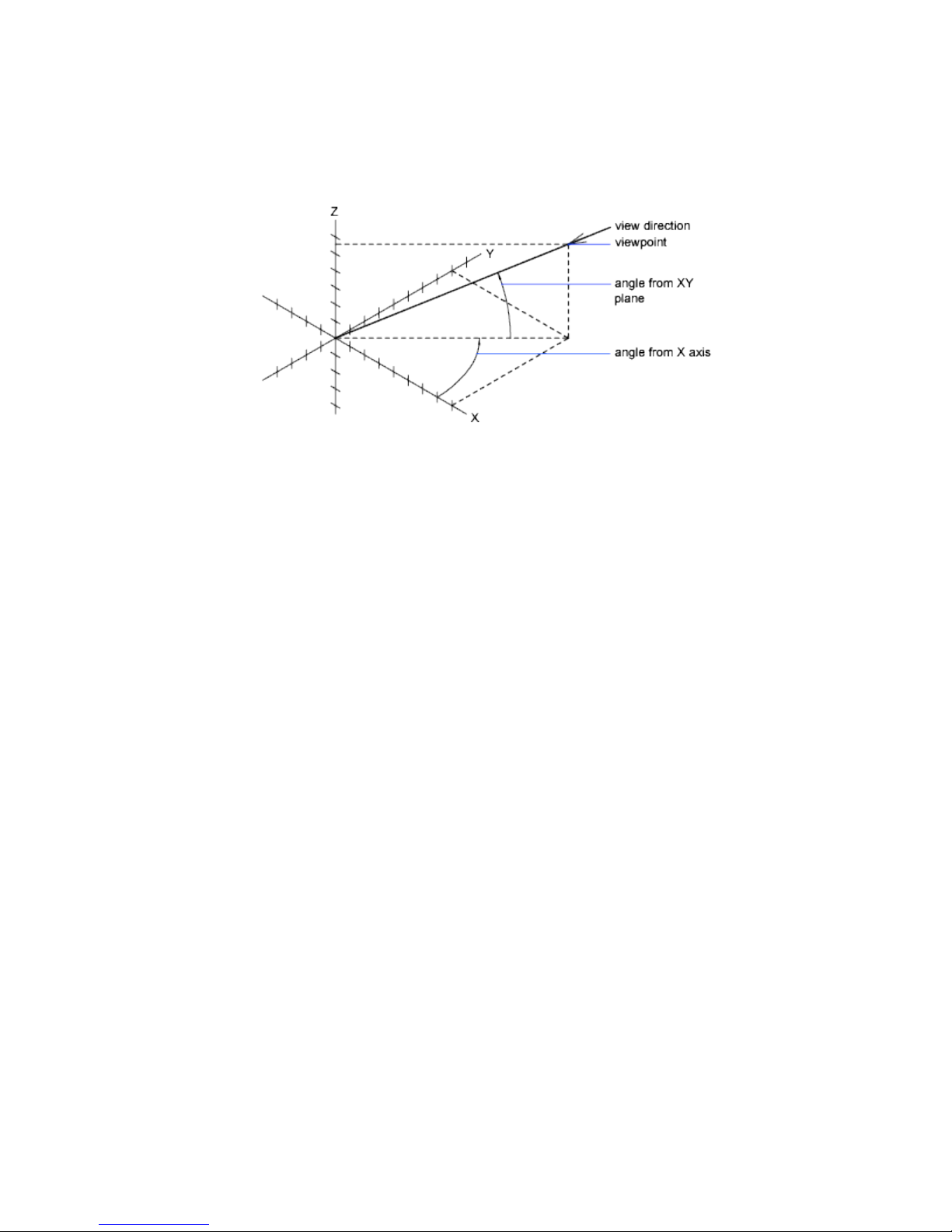
Change to a View of the XY Plane
You can change the current viewpoint to a plan view of the current UCS, a
previously saved UCS, or the WCS.
A plan view is a view aimed toward the origin (0,0,0) from a point on the
positive Z axis. This results in a view of the XY plane.
You can restore the view and coordinate system that is the default for most
drawings by setting the UCS orientation to World and then setting the 3D
view to Plan View.
Hide Lines or Shade 3D Objects
You can create a hidden-line representation or a simple shaded picture of the
objects displayed in the current viewport.
Hide Lines in 3D Objects
Suppress the display of objects—partly or entirely—that are located behind
other objects in three-dimensional views.
You can create a hidden-line representation of the objects displayed in the
current viewport. Hidden-line representations suppress lines, edges, and other
60 | Chapter 4 Control the Drawing Views
Page 81
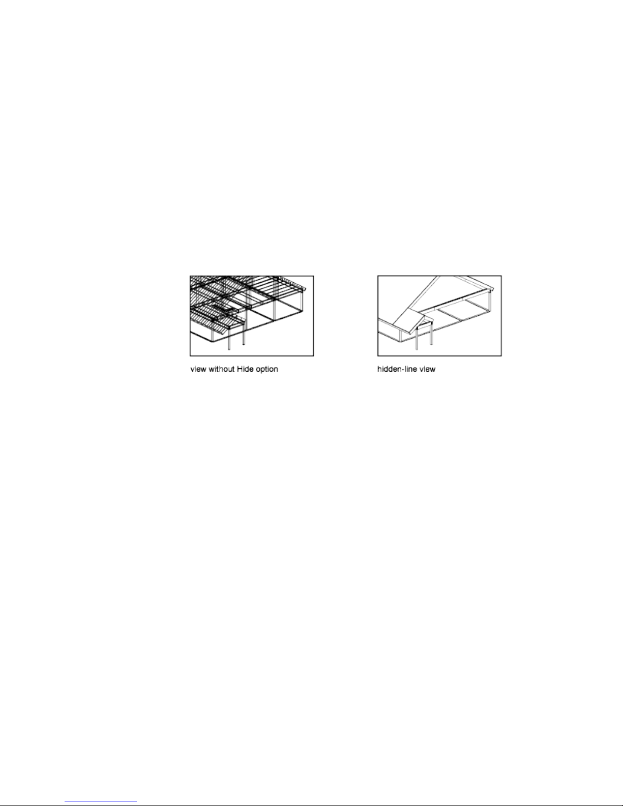
objects—partly or entirely—that are located behind the following types of
objects:
■ Objects with nonzero thickness
■ Circles
■ Two-dimensional solids
■ Wide polylines
■ Surfaces and 3D solids (when viewing models created in AutoCAD)
The illustration below was created with lines that were extruded by giving
them a nonzero thickness.
Objects on layers that are turned off but not frozen can also hide other objects.
You can adjust how hidden lines are displayed by changing the settings in
the Hidden Line Settings dialog box.
Display Views with Hidden Lines Removed
For viewing, you can temporarily suppress hidden lines with HIDE.
HIDE suppresses all hidden lines in a view. When the view is regenerated, all
objects are displayed normally.
See also:
Set Options for Plotted Objects (page 442)
Add Simple Shading to 3D Objects
Generate a simple shaded picture of the objects displayed in the current
viewport.
Change Views | 61
Page 82

You can create a simple shaded picture of the objects displayed in the current
viewport. Shading fills certain objects with a solid color and removes the
display of lines that are located behind the shaded objects. Each object is shaded
using its current color.
In any view, you can shade the following types of objects:
■ Objects with non-zero 3D thickness
■ Circles
■ Solid-filled polygons
■ Wide polylines
■ Surfaces and 3D solids (when viewing models created in AutoCAD)
Choose Shading Options
On systems that display fewer than 256 colors, SHADE produces an image
that removes hidden lines and displays the faces in their original color with
no lighting effect.
You have four shading options:
■ 256 Color. Creates shaded faces with no edge highlighting. You need a
256-color display to see the full effect of this option.
■ 256 Color Edge Highlight. Creates shaded faces with edges highlighted
in the background color. You need a 256-color display with the program's
standard 256-color map to see the full effect of this option.
■ 16 Color Hidden Line. Simulates a hidden-line display. The faces of
polygons are painted in the background color, and the color of visible
edges is determined by the color of the object. You can use any kind of
monitor, including monochrome.
■ 16 Color Filled. Draws faces in their original color but does not shade
them. The program hides hidden lines and traces visible edges in the
background color. You can use this setting on any kind of monitor.
NOTE
The SHADE command produces only flat shading.
62 | Chapter 4 Control the Drawing Views
Page 83

Display Multiple Views in Model Space
To see several views at the same time, you can split the drawing area of the
Model layout into separate viewing areas called model space viewports. You can
save arrangements of model space viewports for reuse at any time.
See also:
Work with Model Space and Paper Space (page 72)
Create and Modify Layout Viewports (page 75)
Set Model Space Viewports
On the Model layout, you can split the drawing area into one or more adjacent
rectangular views known as model space viewports.
Viewports are areas that display different views of your model. As you work
on the Model layout, you can split the drawing area into one or more adjacent
rectangular views known as model space viewports. In large or complex drawings,
displaying different views reduces the time needed to zoom or pan in a single
view. Also, errors you might miss in one view may be apparent in the others.
Viewports created on the Model layout completely fill the drawing area and
do not overlap. As you make changes in one viewport, the others are updated
simultaneously. Three model space viewports are shown in the illustration.
Display Multiple Views in Model Space | 63
Page 84
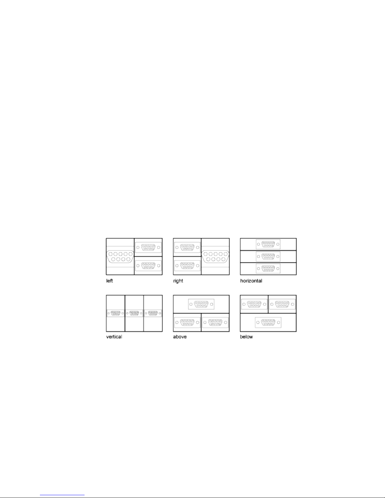
You can also create viewports on a named (paper space) layout. You use those
viewports, called layout viewports, to arrange the views of your drawing on a
sheet. You can move and resize layout viewports. By using layout viewports,
you have more control over the display; for example, you can freeze certain
layers in one layout viewport without affecting the others. For more
information about layouts and layout viewports, see Create Multiple-View
Drawing Layouts (Paper Space) (page 71).
Use Model Space Viewports
With model space viewports, you can do the following:
■ Pan; zoom; set Snap, Grid, and UCS icon modes; and restore named views.
■ Draw from one viewport to another when executing a command.
■ Name a viewport arrangement so that you can reuse it on the Model layout
or insert it on a named layout.
Split and Join Model Space Viewports
The illustrations below show several default model space viewport
configurations.
You can easily modify model space viewports by splitting and joining them.
If you want to join two viewports, they must share a common edge of the
same length.
64 | Chapter 4 Control the Drawing Views
Page 85

Select and Use the Current Viewport
When you use multiple viewports, one of them is the current viewport, which
accepts cursor input and view commands.
When a viewport is current, the cursor is displayed as crosshairs rather than
an arrow, and the viewport boundary is highlighted. You can change the
current viewport at any time except when a View command is in progress.
To make a viewport the current viewport, you click inside it or press Ctrl-R to
cycle through the existing viewports.
To draw a line using two model space viewports, you start the line in the
current viewport, make another viewport current by clicking within it, and
then specify the endpoint of the line in the second viewport. In a large
drawing, you can use this method to draw a line from a detail in one corner
to a detail in a distant corner.
Save and Restore Model Layout Viewport Arrangements
Arrangements of model viewports can be saved and restored by name.
You do not have to set up viewports and views every time you need them.
With VPORTS, viewport arrangements can be saved and later restored by
name. Settings that are saved with viewport arrangements include
■ The number and position of viewports
Display Multiple Views in Model Space | 65
Page 86

■ The views that the viewports contain
■ The grid and snap settings for each viewport
■ The UCS icon display setting for each viewport
You can list, restore, and delete the available viewport arrangements. A
viewport arrangement saved on the Model layout can be inserted on a named
layout.
66 | Chapter 4 Control the Drawing Views
Page 87

Organize Drawings and
Layouts
5
Create Single-View Drawings (Model Space)
To create a two dimensional drawing that has one view, you can create the
drawing and its annotation entirely in model space. This is the traditional
method for creating drawings with AutoCAD LT.
With this method, you create the building, mechanical part, or geographic area
that you want to represent at full scale (1:1), but you create the text, dimensions,
and the title block of the drawing at a scale to match the intended plot scale.
Quick Start for Model Space Drafting
The process of creating and plotting a drawing file in model space is very
different from the process used in manual drafting.
In AutoCAD LT, there are two distinct working environments that are represented
by Model and named layouts.
If you are going to create a two-dimensional drawing that has one view, you
can create both the model and its annotation entirely in model space, not using
a layout. This is the traditional method for creating drawings with AutoCAD
LT. This method is simple but has several limitations, including
■ It is suitable for 2D drawings only
■ It does not support multiple views and view-dependent layer settings
■ Scaling the annotation and title block requires computation unless you use
objects.
67
Page 88

With this method, you always draw geometric objects at full scale (1:1) and
text, dimensions, and other annotation at a scale that will appear at the correct
size when you output the drawing.
For information about using annotative objects and scaling annotations
automatically, see Scale Annotations (page 304).
See also:
Create Multiple-View Drawing Layouts (Paper Space) (page 71)
Draw, Scale, and Annotate in Model Space
If you draw and plot from model space, you must determine and apply a scale
factor to annotate objects before you plot.
You can draw and plot entirely from model space. This method is useful
primarily for two-dimensional drawings that have a single view. With this
method, you use the following process:
■ Determine the unit of measurement (drawing units) for the drawing.
■ Specify the display style for the drawing unit.
■ Calculate and set the scale for dimensions, annotations, and blocks.
■ Draw at full scale (1:1) in model space.
■ Create the annotation and insert the blocks in model space.
■ Print the drawing at the predetermined scale.
You can also use objects if you want to scale annotations automatically. For
information about using annotative objects and scaling annotations
automatically, see Scale Annotations (page 304).
Determine the Unit of Measurement
Before you begin drawing in model space, you determine the unit of
measurement (drawing units) that you plan to use. You decide what each unit
on the screen represents, such as an inch, a millimeter, a kilometer, or some
other unit of measurement. For example, if you are drawing a motor part, you
might decide that one drawing unit equals a millimeter. If you are drawing a
map, you might decide that one unit equals a kilometer.
68 | Chapter 5 Organize Drawings and Layouts
Page 89

Specify the Display Style of Drawing Units
Once you have determined a drawing unit for the drawing, you need to specify
the style for displaying the drawing unit, which includes the unit type and
precision. For example, a value of 14.5 can be displayed as 14.500, 14-1/2, or
1'2-1/2".
Specify the display style of drawing units with the UNITS command. The
default drawing unit type is decimal.
Set the Scale for Annotations and Blocks
Before you draw, you should set the scale for dimensions, annotations, and
blocks in your drawings. Scaling these elements beforehand ensures that they
are at the correct size when you plot the final drawing.
You should enter the scale for the following objects:
■ Text. Set the text height as you create text or by setting a fixed text height
in the text style (STYLE).
■ Dimensions. Set the dimension scale in a dimension style (DIMSTYLE)
or with the DIMSCALE system variable.
■ Linetypes. Set the scale for noncontinuous linetypes with the CELTSCALE
and LTSCALE system variables.
■ Hatch patterns. Set the scale for hatch patterns while creating the hatch
(HATCH), before creating the hatch object with the HPSCALE system
variable, or edit the hatch after it has been created.
■ Blocks.Specify the insertion scale for blocks either as you insert them, or
set an insertion scale in the Insert Block dialog box (INSERT).
The system variables used for inserting blocks are INSUNITS,
INSUNITSDEFSOURCE, and INSUNITSDEFTARGET. This also applies to
the border and title block of the drawing.
You can also use objects if you want to scale annotations automatically. For
information about using annotative objects and scaling annotations
automatically, see Scale Annotations (page 304).
Determine the Scale Factor for Plotting
To plot your drawing from the Model layout, you calculate the exact scale
factor by converting the drawing scale to a ratio of 1:n. This ratio compares
plotted units to drawing units that represent the actual size of the objects you
are drawing.
Create Single-View Drawings (Model Space) | 69
Page 90
For example, if you plan to plot at a scale of 1/4 inch = 1 foot, you would
calculate the scale factor 48 as follows:
1/4" = 12"
1 = 12 x 4
1 (plotted unit) = 48 (drawing units)
Using the same calculation, the scale factor for 1 centimeter = 1 meter is 100,
and the scale factor for 1 inch = 20 feet is 240.
Sample Scale Ratios
The sample architectural scale ratios in the table can be used to calculate text
sizes in model space.
Scale factorScale
To plot text size
at
Set drawing text
size to
30 cm3 mm1001 cm = 1 m
12"1/8"961/8" = 1'-0"
8"1/8"643/16" = 1'-0"
6"1/8"481/4" = 1'-0"
4"1/8"323/8" = 1'-0"
3"1/8"241/2" = 1'-0"
2"1/8"163/4" = 1'-0"
1.5"1/8"121" = 1'-0"
1.0"1/8"81 1/2" = 1'-0"
If you are working in metric units, you might have a sheet size of 210 x 297
mm (A4 size) and a scale factor of 20. You calculate grid limits as follows:
210 x 20 = 4200 mm
70 | Chapter 5 Organize Drawings and Layouts
Page 91

297 x 20 = 5900 mm
See also:
Specify Units and Unit Formats (page 38)
Create Multiple-View Drawing Layouts (Paper
Space)
Paper space is a sheet layout environment where you can specify the size of
your sheet, add a title block, display multiple views of your model, and create
dimensions and notes for your drawing.
Quick Start for Layouts
There are two distinct working environments, or “spaces,” in which you can
create objects in a drawing.
Typically, a model composed of geometric objects is created in a
three-dimensional space called model space. A final layout of specific views
and annotations of this model is created in a two-dimensional space called
paper space.
Working in model space, you draw a model of your subject at 1:1 scale.
Working on a named layout, you create one or more layout viewports,
dimensions, notes, and a title block to represent a drawing sheet.
Each layout viewport is like a picture frame containing a “photograph” of the
model in model space. Each layout viewport contains a view that displays the
model at the scale and orientation that you specify. You can also specify which
layers are visible in each layout viewport.
After you finish arranging the layout, you turn off the layer that contains the
layout viewport objects. The views are still visible, and you can plot the layout
without displaying the viewport boundaries.
Understand the Layout Process
When you use a named layout to prepare your drawing for output, you follow
a series of steps in a process.
Create Multiple-View Drawing Layouts (Paper Space) | 71
Page 92

You design the subject of your drawing in model space and prepare it for
output on a named layout in paper space. A drawing always has at least one
named layout.
Before you can use a layout, it must be initialized. A layout does not contain
any page setup information before it is initialized. Once initialized, layouts
can be drawn upon and output.
Process Summary
When you prepare a layout, you typically step through the following process:
■ Create a model of your subject in model space.
■ Initialize a named layout.
■ Specify layout page settings such as output device, paper size, drawing
area, output scale, and drawing orientation.
■ Insert a title block into the layout (unless you have started with a drawing
template that already has a title block).
■ Create a new layer to be used for layout viewports.
■ Create layout viewports and position them on the layout.
■ Set the orientation, scale, and layer visibility of the view in each layout
viewport.
■ Add dimensions and annotate in the layout as needed.
■ Turn off the layer containing the layout viewports.
■ Output your layout.
You can also use annotative objects if you want to annotate your drawing in
model space and scale the annotations automatically. For information about
using annotative objects and scaling annotations automatically, see Scale
Annotations (page 304).
Work with Model Space and Paper Space
There are several benefits to switching between model space and paper space
to perform certain tasks. Use model space for creating and editing your model.
Use paper space for composing your drawing sheet and defining views.
72 | Chapter 5 Organize Drawings and Layouts
Page 93

Work in Model Space
By default, you start working in a limitless drawing area called model space. In
model space, you draw, view, and edit your model.
You first decide whether one unit represents one millimeter, one centimeter,
one inch, one foot, or whatever unit is most convenient or customary in your
business. You then create your model at 1:1 scale.
In model space, you can view and edit model space objects. The crosshairs
cursor is active over the entire drawing area.
In model space, you can also define named views that you display in layout
viewports on a layout.
Work on a Named Layout
Named layouts access an area called paper space. In paper space, you place your
title block, create layout viewports to display views, dimension your drawing,
and add notes.
In paper space, one unit represents the actual distance on a sheet of paper.
The units will be in either millimeters or inches, depending on how you
configure your page setup.
On a named layout, you can view and edit paper space objects, such as layout
viewports and title blocks. You can also move an object (such as a leader or a
title block) from model space to paper space (or vice versa). The crosshairs
cursor is active over the entire layout area.
Create Additional Named Layouts
By default, a new drawing starts with two named layouts, named Layout1 and
Layout2. If you use a drawing template or open an existing drawing, the
layouts in your drawing may be named differently.
You can create a new layout using one of the following methods:
■ Add a new layout with no settings and then specify the settings in the
Page Setup Manager.
■ Copy a layout and its settings from the current drawing file.
■ Import a layout from an existing drawing template (DWT) file or drawing
(DWG) file.
Create Multiple-View Drawing Layouts (Paper Space) | 73
Page 94

Access Model Space from a Layout Viewport
You can access model space from a layout viewport to edit objects, to freeze
and thaw layers, and to adjust the view.
After creating viewport objects, you can access model space from a layout
viewport to perform the following tasks:
■ Create and modify objects in model space inside the layout viewport.
■ Pan the view inside the layout viewport and change layer visibility.
The method you use to access model space depends on what you plan to do.
Create and Modify Objects in a Layout Viewport
If you plan to create or modify objects, use the Maximize Viewport button on
the status bar to make the layout viewport fill the application window. The
center point and the layer visibility settings of the layout viewport are retained,
and the surrounding objects are displayed.
You can pan and zoom while you are working in model space, but when you
restore the viewport to return to paper space, the position and scale of the
objects in the layout viewport are restored.
NOTE If you use PLOT while a viewport is maximized, the layout is restored before
the Print dialog box is displayed. If you save and close the drawing while a viewport
is maximized, the drawing opens with the named layout restored.
If you choose to switch to the default model space to make changes, the layer
visibility settings are the settings for the drawing as a whole, not the settings
for that particular layout viewport. Also, the view is not centered or magnified
the same way it is in the layout viewport.
Adjust the View in a Layout Viewport
If you plan to pan the view and change the visibility of layers, double-click
within a layout viewport to access model space. The viewport border becomes
thicker, and the crosshairs cursor is visible in the current viewport only. All
active viewports in the layout remain visible while you work. You can freeze
and thaw layers in the current viewport in the Layers palette, and you can
pan the view. To return to paper space, double-click an empty area on the
layout outside a viewport. The changes you made are displayed in the viewport.
74 | Chapter 5 Organize Drawings and Layouts
Page 95

If you set the scale in the layout viewport before you access model space, you
can lock the scale to prevent changes. When the scale is locked, you cannot
use ZOOM while you work in model space.
Create and Modify Layout Viewports
You can create a single layout viewport that fits the entire layout or create
multiple layout viewports in the layout. Once you create the viewports, you
can change their size, their properties, and also scale and move them as needed.
NOTE
It is important to create layout viewports on their own layer. When you are
ready to output your drawing, you can turn off the layer and output the layout
without the boundaries of the layout viewports.
With MVIEW, you have several options for creating one or more layout
viewports. You can also use COPY and ARRAY to create multiple layout
viewports.
Create Nonrectangular Layout Viewports
You can create a new viewport with nonrectangular boundaries by converting
an object drawn in paper space into a layout viewport.
Create Multiple-View Drawing Layouts (Paper Space) | 75
Page 96

You can use the MVIEW command to create nonrectangular viewports.
■ With the Object option, you can select a closed object, such as a circle or
closed polyline created in paper space, to convert into a layout viewport.
The object that defines the viewport boundary is associated with the
viewport after the viewport is created
■ With the Polygonal option, you can create a nonrectangular layout
viewport by specifying points. The prompts are the same as the prompts
for creating a polyline
NOTE When you want to suppress the display of the boundary of a layout viewport,
you should turn off the layer of the nonrectangular viewport instead of freezing
it. If the layer of a nonrectangular layout viewport is frozen, the viewport is not
clipped correctly.
Redefine Layout Viewport Boundaries
You can redefine the boundary of a layout viewport by using the VPCLIP
command. You can either select an existing object to designate as the new
boundary, or specify the points of a new boundary. The new boundary does
not clip the old boundary, it redefines it.
A nonrectangular viewport consists of two objects: the viewport itself and the
clipping boundary. You can make changes to the viewport, the clipping
boundary, or both.
NOTE In the Properties Inspector, the default selection for a nonrectangular
viewport is Viewport. This is because you are more likely to change the properties
of the viewport than of the clipping boundary.
Resize Layout Viewports
If you want to change the shape or size of a layout viewport, you can use grips
to edit the vertices just as you edit any object with grips.
Control Views in Layout Viewports
When you create a layout, you can add layout viewports that act as windows
into model space. In each layout viewport, you can control the view that is
displayed.
76 | Chapter 5 Organize Drawings and Layouts
Page 97

Scale Views in Layout Viewports
To scale each displayed view in output accurately, set the scale of each view
relative to paper space.
You can change the view scale of the viewport using
■ The Properties Inspector
■ The XP option of the ZOOM command
■ The Viewports Scale on the status bar
NOTE You can modify the list of scales that are displayed in all view and print
scale lists with SCALELISTEDIT. After you add a new scale to the default scale list,
you can use the Reset button in the Edit Drawing Scales dialog box to add the
new scale to your drawing.
When you work in a layout, the scale factor of a view in a layout viewport
represents a ratio between the actual size of the model displayed in the
viewport and the size of the layout. The ratio is determined by dividing the
paper space units by the model space units. For example, for a quarter-scale
drawing, the ratio would be a scale factor of one paper space unit to four model
space units, or 1:4.
Scaling or stretching the layout viewport border does not change the scale of
the view within the viewport.
When creating a new drawing based on a template, the scales in the template
are used in the new drawing. The scales in the user profile are not imported.
Lock the Scale of Layout Viewports
Once you set the viewport scale, you cannot zoom within a viewport without
changing the viewport scale. By locking the viewport scale first, you can zoom
in to view different levels of detail in your viewport without altering the
viewport scale.
Scale locking locks the scale that you set for the selected viewport. Once the
scale is locked, you can continue to modify the geometry in the viewport
without affecting the viewport scale. If you turn a viewport's scale locking on,
most of the viewing commands, such as VPOINT, PLAN, and VIEW, no longer
function in that viewport.
Create Multiple-View Drawing Layouts (Paper Space) | 77
Page 98

NOTE Viewport scale locking is also available for nonrectangular viewports. To
lock a nonrectangular viewport, you must perform an extra step in the Properties
Inspector to select the viewport object rather than the viewport clipping boundary.
Annotative Objects and Scaling
Annotative objects are defined at a paper height instead of a model size and
assigned one or more scales. These objects are scaled based on the current
annotation scale setting and automatically displayed at the correct size in the
layout or when plotted. The annotation scale controls the size of the annotative
objects relative to the model geometry in the drawing.
You can specify the default list of scales available for layout viewports, page
layouts, and printing in Default Scale List dialog box.
For more information about annotation scaling, see Scale Annotations (page
304).
Control Visibility in Layout Viewports
You can control the visibility of objects in layout viewports using several
methods. These methods are useful for emphasizing or hiding different
elements of a drawing, and for reducing screen regeneration time.
See also:
Display Annotative Objects (page 314)
Freeze Specified Layers in a Layout Viewport
A major benefit to using layout viewports is that you can selectively freeze
layers in each layout viewport. You can also specify default visibility settings
for new viewports and for new layers. As a result, you can view different objects
in each layout viewport.
You can freeze or thaw layers in current and future layout viewports without
affecting other viewports. Frozen layers are invisible. They are not regenerated
or plotted. In the illustration, the layer showing terrain has been frozen in
one viewport.
78 | Chapter 5 Organize Drawings and Layouts
Page 99
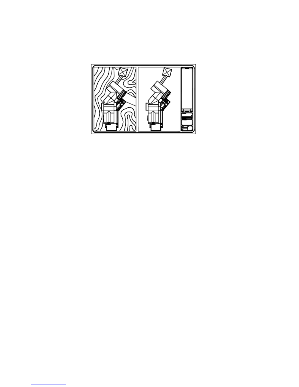
Thawing the layer restores visibility. The easiest way to freeze or thaw layers
in the current viewport is to use the Layers palette.
In the Layers palette, on the right side, use the column labeled VP Freeze to
freeze one or more layers in the current layout viewport. To display the VP
Freeze column, you must be on a layout. Specify the current layout viewport
by double-clicking anywhere within its borders.
Freeze or Thaw Layers Automatically in New Layout Viewports
You can set visibility defaults for specific layers in all new layout viewports.
For example, you can restrict the display of dimensions by freezing the
DIMENSIONS layer in all new viewports. If you create a viewport that requires
dimensions, you can override the default setting by changing the setting in
the current viewport. Changing the default for new viewports does not affect
existing viewports.
Create New Layers That Are Frozen in All Layout Viewports
You can create new layers that are frozen in all existing and new layout
viewports. Then you can thaw the layers in the viewports you specify. This is
a shortcut for creating a new layer that is visible only in a single viewport.
Screen Objects in Layout Viewports
Screening refers to applying less ink to an object when it is plotted. The object
appears dimmer on the screen and output to paper. Screening can be used to
help differentiate objects in a drawing without changing the objects' color
properties.
Create Multiple-View Drawing Layouts (Paper Space) | 79
Page 100

To assign a screening value to an object, you must assign a plot style to the
object, and then define the screening value in that plot style.
You can assign a screening value from 0 to 100. The default setting, 100, means
no screening is applied, and the object is displayed with normal ink intensity.
A screening value of 0 means the object contains no ink and is thus invisible
in that viewport.
See also:
Set Options for Plotted Objects (page 442)
Turn Layout Viewports On or Off
You can save time by turning some layout viewports off or by limiting the
number of active viewports.
Displaying a large number of active layout viewports can affect your system's
performance as the content of each layout viewport regenerates. You can save
time by turning some layout viewports off or by limiting the number of active
viewports. The following illustration shows the effects of turning off two
layout viewports.
New layout viewports are turned on by default. If you turn off the layout
viewports you aren't using, you can copy layout viewports without waiting
for each one to regenerate.
If you don't want to plot a layout viewport, you can turn the layout viewport
off.
80 | Chapter 5 Organize Drawings and Layouts
 Loading...