

Page 1
Getting Started
AutoCAD
®
Electrical 2005
22502-010000-5000A May 11, 2004
Page 2

Copyright © 2004 Autodesk, Inc.
All Rights Reserved
This publication, or parts thereof, may not be reproduced in any form, by any method, for any purpose.
AUTODESK, INC. MAKES NO WARRANTY, EITHER EXPRESSED OR IMPLIED, INCLUDING BUT NOT LIMITED TO ANY IMPLIED
WARRANTIES OF MERCHANTABILITY OR FITNESS FOR A PARTICULAR PURPOSE, REGARDING THESE MATERIALS AND
MAKES SUCH MATERIALS AVAILABLE SOLELY ON AN “AS-IS” BASIS.
IN NO EVENT SHALL AUTODESK, INC. BE LIABLE TO ANYONE FOR SPECIAL, COLLATERAL, INCIDENTAL, OR
CONSEQUENTIAL DAMAGES IN CONNECTION WITH OR ARISING OUT OF PURCHASE OR USE OF THESE MATERIALS. THE
SOLE AND EXCLUSIVE LIABILITY TO AUTODESK, INC., REGARDLESS OF THE FORM OF ACTION, SHALL NOT EXCEED THE
PURCHASE PRICE OF THE MATERIALS DESCRIBED HEREIN.
Autodesk, Inc. reserves the right to revise and improve its products as it sees fit. This publication describes the state of this product
at the time of its publication, and may not reflect the product at all times in the future.
Autodesk Trademarks
The following are registered trademarks of Autodesk, Inc., in the USA and/or other countries: 3D Props, 3D Studio, 3D Studio MAX, 3D
Studio VIZ, 3DSurfer, 3ds max, ActiveShapes, ActiveShapes (logo), Actrix, ADI, AEC Authority (logo), AEC-X, Animator Pro, Animator
Studio, ATC, AUGI, AutoCAD, AutoCAD LT, AutoCAD Map, Autodesk, Autodesk Envision, Autodesk Inventor, Autodesk (logo), Autodesk
Map, Autodesk MapGuide, Autodesk Streamline, Autodesk University (logo), Autodesk View, Autodesk WalkThrough, Autodesk World,
AutoLISP, AutoSketch, backdraft, Biped, bringing information down to earth, Buzzsaw, CAD Overlay, Character Studio, Cinepak, Cinepak
(logo), cleaner, Codec Central, combustion, Design Your World, Design Your World (logo), EditDV, Education by Design, gmax, Heidi,
HOOPS, Hyperwire, i-drop, Inside Track, IntroDV, Kinetix, MaterialSpec, Mechanical Desktop, NAAUG, ObjectARX, PeopleTracker,
Physique, Planix, Powered with Autodesk Technology (logo), ProjectPoint, RadioRay, Reactor, Revit, Softdesk, Texture Universe, The AEC
Authority, The Auto Architect, VISION*, Visual, Visual Construction, Visual Drainage, Visual Hydro, Visual Landscape, Visual Roads, Visual
Survey, Visual Toolbox, Visual Tugboat, Visual LISP, Volo, WHIP!, and WHIP! (logo).
The following are trademarks of Autodesk, Inc., in the USA and/or other countries: AutoCAD Learning Assistance, AutoCAD LT Learning
Assistance, AutoCAD Simulator, AutoCAD SQL Extension, AutoCAD SQL Interface, AutoSnap, AutoTrack, Built with ObjectARX (logo),
burn, Buzzsaw.com, CAiCE, Cinestream, Civil 3D, cleaner central, ClearScale, Colour Warper, Content Explorer, Dancing Baby (image),
DesignCenter, Design Doctor, Designer's Toolkit, DesignProf, DesignServer, Design Web Format, DWF, DWFit, DWG Linking, DXF,
Extending the Design Team, GDX Driver, gmax (logo), gmax ready (logo),Heads-up Design, jobnet, lustre, ObjectDBX, onscreen onair
online, Plans & Specs, Plasma, PolarSnap, Productstream, Real-time Roto, Render Queue, Visual Bridge, Visual Syllabus, and Where Design
Connects.
The following are registered trademarks of Autodesk Canada Inc. in the USA and/or Canada, and/or other countries: discreet, fire, flame,
flint, flint RT, frost, glass, inferno, MountStone, riot, river, smoke, sparks, stone, stream, vapour, wire.
The following are trademarks of Autodesk Canada Inc., in the USA, Canada, and/or other countries: backburner, Multi-Master Editing.
All other brand names, product names or trademarks belong to their respective holders.
ACIS Copyright © 1989-2001 Spatial Corp. Portions Copyright © 2002-2004 Autodesk, Inc.
Copyright © 1997 Microsoft Corporation. All rights reserved.
International CorrectSpell™ Spelling Correction System © 1995 by Lernout & Hauspie Speech Products, N.V. All rights reserved.
PANTONE ® Colors displayed in the software application or in the user documentation may not match PANTONE-identified standards.
Consult current PANTONE Color Publications for accurate color.
PANTONE ® and other Pantone, Inc. trademarks are the property of Pantone, Inc. © Pantone, Inc., 2002
Pantone, Inc. is the copyright owner of color data and/or software which are licensed to Autodesk, Inc., to distribute for use only in
combination with certain Autodesk software products. PANTONE Color Data and/or Software shall not be copied onto another disk or into
memory unless as part of the execution of this Autodesk software product.
Portions Copyright © 1991-1996 Arthur D. Applegate. All rights reserved.
Portions of this software are based on the work of the Independent JPEG Group.
RAL DESIGN © RAL, Sankt Augustin, 2002
RAL CLASSIC © RAL, Sankt Augustin, 2002
Representation of the RAL Colors is done with the approval of RAL Deutsches Institut für Gütesicherung und Kennzeichnung e.V. (RAL
German Institute for Quality Assurance and Certification, re. Assoc.), D-53757 Sankt Augustin.
Copyright © Stade de France - Macary, Zublena et Regembal, Costantini - Architectes, ADAGP - Paris - 2003
Typefaces from the Bitstream ® typeface library copyright 1992.
Typefaces from Payne Loving Trust © 1996. All rights reserved.
Genius™, Genius CAD Software GmbH and CoKG, licensed to Autodesk Inc. for limited use in connection with Genius™14, Genius™ LT,
Genius™ Desktop, Genius™ Mold, Genius™ Motion, Genius™ Pool, Genius™ Profile, Genius™ SAP, Genius™ TNT, and Genius™ Vario.
Cypress Enable™, Cypress Software, Inc.
dBASE™, Ksoft, Inc.
SPEC™, Associated Spring/Barnes Group, Inc.
LUCA TCP/IP Package, Portions Copyright © 1997 Langener GmbH. All rights reserved.
Stingray Objective Toolkit & Objective Grid © Rogue Wave Software, Inc.
PKWARE Data Compression Library ©, PKWARE, Inc.
Use, duplication, or disclosure by the U. S. Government is subject to restrictions as set forth in FAR 12.212 (Commercial Computer
Software-Restricted Rights) and DFAR 227.7202 (Rights in Technical Data and Computer Software), as applicable.
Autodesk Canada Inc. Trademarks
Third Party Trademarks
Third Party Software Program Credits
GOVERNMENT USE
1 2 3 4 5 6 7 8 9 10
Page 3

Contents
Introduction . . . . . . . . . . . . . . . . . . . . . . . . . . . . . . . . . . . . . . . . . . . 1
About AutoCAD Electrical. . . . . . . . . . . . . . . . . . . . . . . . . . . . . . . . . . . . . . . 2
Learning AutoCAD Electrical . . . . . . . . . . . . . . . . . . . . . . . . . . . . . . . . . . . . 2
Using Help. . . . . . . . . . . . . . . . . . . . . . . . . . . . . . . . . . . . . . . . . . . . . . . . . . . 2
Selecting Projects. . . . . . . . . . . . . . . . . . . . . . . . . . . . . . . . . . . . . . . . . . . . . . 3
Add Existing Drawings. . . . . . . . . . . . . . . . . . . . . . . . . . . . . . . . . . . . . 3
Chapter 1 Wires . . . . . . . . . . . . . . . . . . . . . . . . . . . . . . . . . . . . . . . . . . . . . . . . . 7
About Wires. . . . . . . . . . . . . . . . . . . . . . . . . . . . . . . . . . . . . . . . . . . . . . . . . . 8
Inserting Wires . . . . . . . . . . . . . . . . . . . . . . . . . . . . . . . . . . . . . . . . . . . . . . . 8
Trimming Wires . . . . . . . . . . . . . . . . . . . . . . . . . . . . . . . . . . . . . . . . . . . . . 10
Chapter 2 Schematic Components . . . . . . . . . . . . . . . . . . . . . . . . . . . . . . . . . 11
About Schematic Symbols . . . . . . . . . . . . . . . . . . . . . . . . . . . . . . . . . . . . . . 12
Inserting Components . . . . . . . . . . . . . . . . . . . . . . . . . . . . . . . . . . . . . . . . 12
Inserting Parent Components . . . . . . . . . . . . . . . . . . . . . . . . . . . . . . 12
Scooting Components . . . . . . . . . . . . . . . . . . . . . . . . . . . . . . . . . . . . 15
Inserting Child Components. . . . . . . . . . . . . . . . . . . . . . . . . . . . . . . 15
Aligning Components . . . . . . . . . . . . . . . . . . . . . . . . . . . . . . . . . . . . 18
Inserting Push Buttons. . . . . . . . . . . . . . . . . . . . . . . . . . . . . . . . . . . . 18
Inserting Pilot Lights . . . . . . . . . . . . . . . . . . . . . . . . . . . . . . . . . . . . . 20
Inserting System Reset Buttons . . . . . . . . . . . . . . . . . . . . . . . . . . . . . 21
Generating Component Reports . . . . . . . . . . . . . . . . . . . . . . . . . . . . . . . . . 23
Contents | iii
Page 4

Chapter 3 Drawings . . . . . . . . . . . . . . . . . . . . . . . . . . . . . . . . . . . . . . . . . . . . . 25
Working with Templates . . . . . . . . . . . . . . . . . . . . . . . . . . . . . . . . . . . . . . .26
Selecting Templates. . . . . . . . . . . . . . . . . . . . . . . . . . . . . . . . . . . . . . .26
Inserting Ladders . . . . . . . . . . . . . . . . . . . . . . . . . . . . . . . . . . . . . . . . . . . . .27
Inserting 3-Phase Wires . . . . . . . . . . . . . . . . . . . . . . . . . . . . . . . . . . . . . . . .31
Adding Drawings to Projects . . . . . . . . . . . . . . . . . . . . . . . . . . . . . . . . . . . .33
Adding Drawing Descriptions. . . . . . . . . . . . . . . . . . . . . . . . . . . . . . .35
Chapter 4 PLC . . . . . . . . . . . . . . . . . . . . . . . . . . . . . . . . . . . . . . . . . . . . . . . . . 37
About PLC Modules . . . . . . . . . . . . . . . . . . . . . . . . . . . . . . . . . . . . . . . . . . .38
Inserting PLC modules . . . . . . . . . . . . . . . . . . . . . . . . . . . . . . . . . . . . . . . . .38
Removing Ladder Rungs. . . . . . . . . . . . . . . . . . . . . . . . . . . . . . . . . . . . . . . .43
Using Multiple Insert Component. . . . . . . . . . . . . . . . . . . . . . . . . . . . . . . .44
Chapter 5 Wire Numbers . . . . . . . . . . . . . . . . . . . . . . . . . . . . . . . . . . . . . . . . . 49
About Wire Numbers . . . . . . . . . . . . . . . . . . . . . . . . . . . . . . . . . . . . . . . . . .50
Attaching Source Signal Arrows . . . . . . . . . . . . . . . . . . . . . . . . . . . . . . . . . .50
Attaching Destination Signal Arrows. . . . . . . . . . . . . . . . . . . . . . . . . . . . . .52
Inserting Wire Numbers. . . . . . . . . . . . . . . . . . . . . . . . . . . . . . . . . . . . . . . .58
Deleting Wire Numbers . . . . . . . . . . . . . . . . . . . . . . . . . . . . . . . . . . . . . . . .61
Chapter 6 Panel Layouts . . . . . . . . . . . . . . . . . . . . . . . . . . . . . . . . . . . . . . . . . 63
About Panel Layouts. . . . . . . . . . . . . . . . . . . . . . . . . . . . . . . . . . . . . . . . . . .64
Inserting Panel Components . . . . . . . . . . . . . . . . . . . . . . . . . . . . . . . . . . . .64
Modifying Attributes . . . . . . . . . . . . . . . . . . . . . . . . . . . . . . . . . . . . . . . . . .77
Inserting Nameplate Footprints . . . . . . . . . . . . . . . . . . . . . . . . . . . . . . . . . .79
iv | Contents
Index . . . . . . . . . . . . . . . . . . . . . . . . . . . . . . . . . . . . . . . . . . . . . . . . 83
Page 5

Introduction
In This Chapter
AutoCAD® Electrical software provides tools that extend
®
the capabilities of AutoCAD
build and manage an electrical controls drawing set.
This manual provides conceptual information to help
get you started and exercises that introduce you to the
capabilities of AutoCAD Electrical.
allowing you to quickly
■ About AutoCAD Electrical
■ Learning AutoCAD Electrical
■ Using Help
■ Selecting a Project
1
Page 6

About AutoCAD Electrical
All of the AutoCAD commands and features are available while working on
AutoCAD Electrical drawings. All intelligence is carried directly on the
drawing using AutoCAD blocks with attributes and XDATA. AutoCAD
Electrical does not require any underlying database.
Learning AutoCAD Electrical
It is assumed that you have a working knowledge of the AutoCAD interface
and tools. If you do not, use the integrated Design Support System (DSS) to
access the online documentation.
It is also recommended that you have a working knowledge of Microsoft®
Windows NT® 4.0, Windows 2000, or Windows XP, and a working
knowledge of electrical design and schematic ladder wiring diagrams.
Using Help
As you work, you may need additional information on the task you are
performing. The AutoCAD Electrical Help system provides detailed concepts,
procedures, and reference information about every product feature. To access
the Help system:
■ Select Help ➤ Electrical Help Topics from the standard toolbar.
■ Click the Help button or press F1 within a dialog box.
2 | Introduction
Page 7
Selecting Projects
For your convenience, you can select a project file for the exercises in this
book.
NOTE You must install the JIC drawing standards for these exercises to
function properly.
To select an AutoCAD Electrical project
1 Click the Project New/Existing tool.
Menu Projects ➤ Project ➤ Project New/Existing
2 In the Project dialog box, click the Pick Project button.
3 In the Recent Projects dialog box, click the Other Projects button.
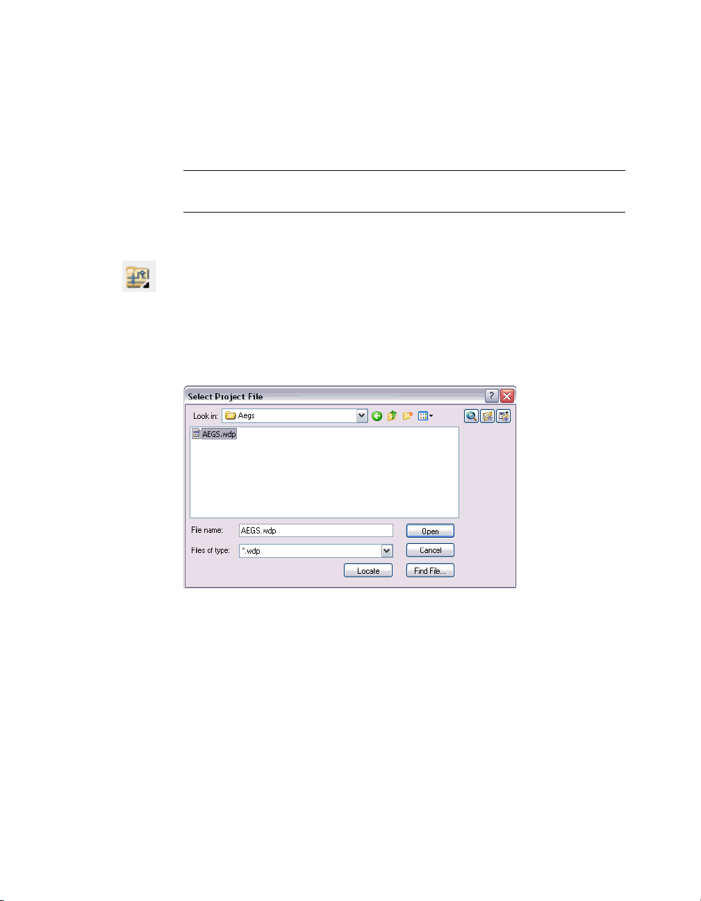
4 In the Select Project file, select AEGS.wdp from the AeData/Proj/Aegs directory,
and then click Open.
Add Existing Drawings
Add existing drawings to the active project.
Selecting Projects | 3
Page 8
To add drawings to the project file
1 In the Project aegs dialog box, click the Add button.
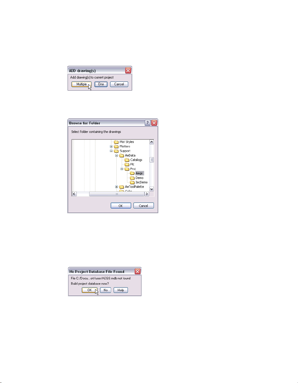
2 In the ADD drawing(s) dialog box, click Multiple to add multiple drawings to
the current project.
3 In the Browse for Folder dialog box, choose the Aegs folder, and then click
OK.
4 In the ADD Drawings(s) to Current Project dialog box, select drawings
DEMO01.dwg to DEMO09.dwg, and then click OK.
The Project aegs dialog box is displayed with the files listed in the Project
Drawing List section.
5 Click OK Project in the Project aegs dialog box.
6 In the No Project Database File Found dialog box, click OK.
You now have convenient access to the needed files when you start using the
exercises in this book.
View drawings using the Project aegs dialog box.
4 | Introduction
Page 9

To quickly view drawings in a project
1 Click the Project New/Existing tool.
Menu Projects ➤ Project ➤ Project New/Existing
2 Highlight demo04.dwg.
3 In the Project aegs dialog box, Project Drawing List section, click the View
button.
4 In the Project aegs dialog box, continue to click the drawing name you want
to preview.
5 When you have finished viewing the drawings, click the Close button in the
Drawing Preview dialog box.
After you open a drawing, you can still quickly view drawings using the Next
and Previous Project Drawing tool.
To view project drawings once a drawing is open
1 In the Project aegs dialog box, double-click demo04.dwg to open.
2 Use the navigation tools Previous Project Drawing and Next Project Drawing
to view the drawings.
This is the end of this tutorial chapter.
Selecting Projects | 5
Page 10

6
Page 11

Wires
In This Chapter
1
AutoCAD® Electrical treats AutoCAD line entities as
wires when the lines are placed on an AutoCAD
Electrical defined wire layer. These lines get tagged with
wire numbers and show up in various wire connection
reports. Two wire segments connect if the end of one
wire segment touches or falls with a small trap distance
of any part of the other wire segment. This connection
can be at the end of the other wire or anywhere along
the length of the other wire. AutoCAD Electrical
considers a wire connected to a component if the wire
end falls within a trap distance from the wire
connection-point attribute of a component.
■ About wires
■ Inserting wires
■ Trimming wires
7
Page 12
About Wires
An AutoCAD Electrical wire is an AutoCAD line entity on an AutoCAD
Electrical wire layer. The wire layer for a new wire segment is determined by:
■ Wires that begin or end in space or begin and end at a component
connection point, are put on the current layer (if it's a wire layer) or on
the first wire layer AutoCAD Electrical finds in a layer name search.
■ Wires that begin at an existing wire take on the same layer as the
beginning wire.
■ Wires that begin in space or at a component and end at an existing wire
take on the layer of the ending wire.
Inserting Wires
You can start or end a wire segment in empty space, from an existing wire
segment, or from an existing component. If you start from a component, the
wire segment snaps to the wire connection terminal closest to your pick
point on that symbol. If the wire segment ends at another wire segment, a
DOT (block name wddot.dwg) is applied if appropriate. If it ends at another
component, the segment connects to the wire connection terminal closest to
your pick point on that symbol.
To insert single phase wiring
1 Click the Project tool to open the aegs project.
Menu Projects ➤ Project ➤ Project New/Existing
2 In the Project dialog box, Project Drawing List section, double-click
demo04.dwg to open the drawing.
3 Zoom in on the upper left corner of the drawing.
4 Click the Add Rung tool.
Menu Wires ➤ Add Rung
8 | Chapter 1 Wires
Page 13
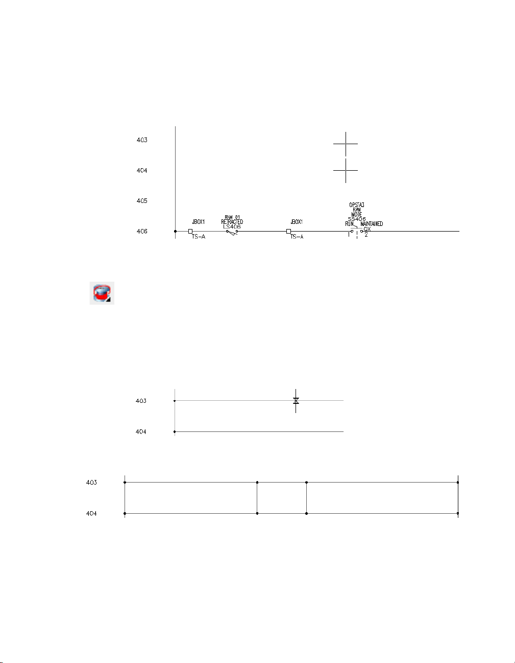
5 Respond to the prompts as follows:
Add rung passing through this location:
Select a location between the two vertical bus wires beside line reference 403 (1)
Add rung passing through this location: Select a location between the two vertical
bus wires beside line reference 404, underneath the newly created rung (2)
1
2
Two horizontal wires are created.
Next, create two vertical wires between the two horizontal wires.
6 Click the Insert Wire tool.
Menu Wires ➤ Insert Wire
7 Respond to the prompts as follows:
Select component or branch for WIRE (S=show connections):
Select the top wire at line reference 403(1)
Select component or branch for WIRE (S=show connections): to: (V=start
Vertical;H=start Horizontal): Select the lower wire at line reference 404 (2)
1
2
8 Insert another wire to the right of the new wire.
The inserted wires resemble the following:
Inserting Wires | 9
Page 14
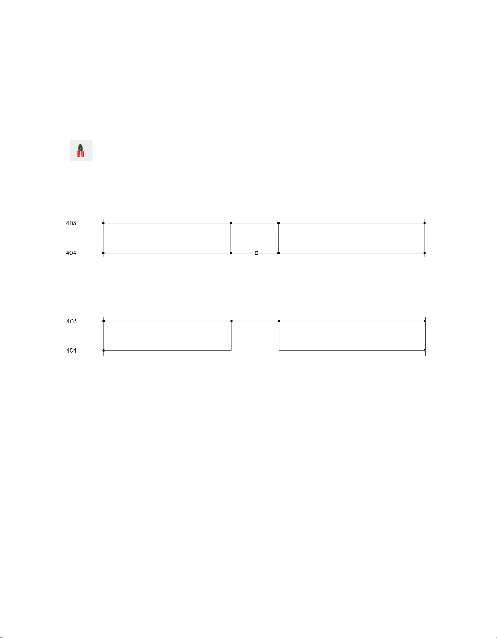
Trimming Wires
After you insert wires, you may need to trim them. The Trim Wire tool
removes wire segments. You can trim single or multiple wires.
To trim a wire
1 Click the Trim Wire tool.
Menu Wires ➤ Trim Wire
2 Respond to the prompts as follows:
Fence/Zext/<Select wire to TRIM>:
Specify the wire segment at line reference 404 between the two vertical wires (1)
Wire segments are trimmed back to a connecting dot, a component, or
completely if neither is encountered along the segment. Any connection
dots that are no longer needed are removed.
The trimmed wire resembles the following image:
1
This is the end of this tutorial chapter.
10 | Chapter 1 Wires
Page 15

Schematic Components
In This Chapter
2
An AutoCAD® Electrical schematic component is an
AutoCAD block with certain expected attributes. When
inserting components, you can use AutoCAD Electrical
tools to automatically break wires, assign unique
component tags, cross reference related components,
and enter values for catalog information, component
descriptions, and location codes.
■ About schematic components
■ Inserting parent components
■ Inserting child components
■ Generating component reports
11
Page 16
About Schematic Symbols
AutoCAD Electrical supplies a schematic symbol dialog box for inserting
schematic components. Besides making it easy to find and insert the desired
symbol, it also triggers a number of additional features such as automatic
wire breaks, component tagging, real-time cross-referencing, and component
annotation.
Inserting Components
AutoCAD Electrical employs a parent/child relationship for schematic
components. A relay coil with a certain number of contacts is represented by
the parent coil symbol and the child contact symbols. When the parent coil
symbol is inserted, it is assigned a unique component tag. When the child
contact symbols are inserted, the child is related to the parent and the parent
tag is assigned to the child symbol.
Use the Insert Component dialog box to insert components into demo04.dwg.
Inserting Parent Components
Start by inserting the parent component.
To insert a parent component
1 Click the Insert Component tool.
Menu Components ➤ Insert Component
2 In the Insert Component: JIC Schematic Symbols dialog box, click the Relays
and Contacts button.
3 In the JIC: Relays and Contacts dialog box, click the Relay Coil.
4 Respond to the prompts as follows:
Specify insertion point: Position the component on the wire at line reference 403
near the neutral wire and click (1)
12 | Chapter 2 Schematic Components
1
Page 17
5 In the Insert/Edit Component dialog box, verify the Component Tag is set to
CR403, and then click the Lookup button in the Catalog Data section of the
dialog box.
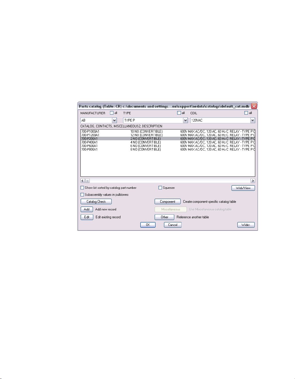
6 In the Parts catalog list dialog box, select:
MANUFACTURER: AB
TYPE: TYPE P
In the CATALOG, CONTACTS, MISCELLANEOUS2, DESCRIPTION list, select
Catalog Number: 700-P200A1
7 Click the Catalog Check button to display the BOM information associated
with the selected part number.
8 In the Bill Of Materials Check dialog box, click the Close button.
9 In the Parts catalog dialog box, click OK.
10 In the Insert/Edit Component dialog box, Description section, specify:
Line 1: MASTER CONTROL
Line 2: RELAY
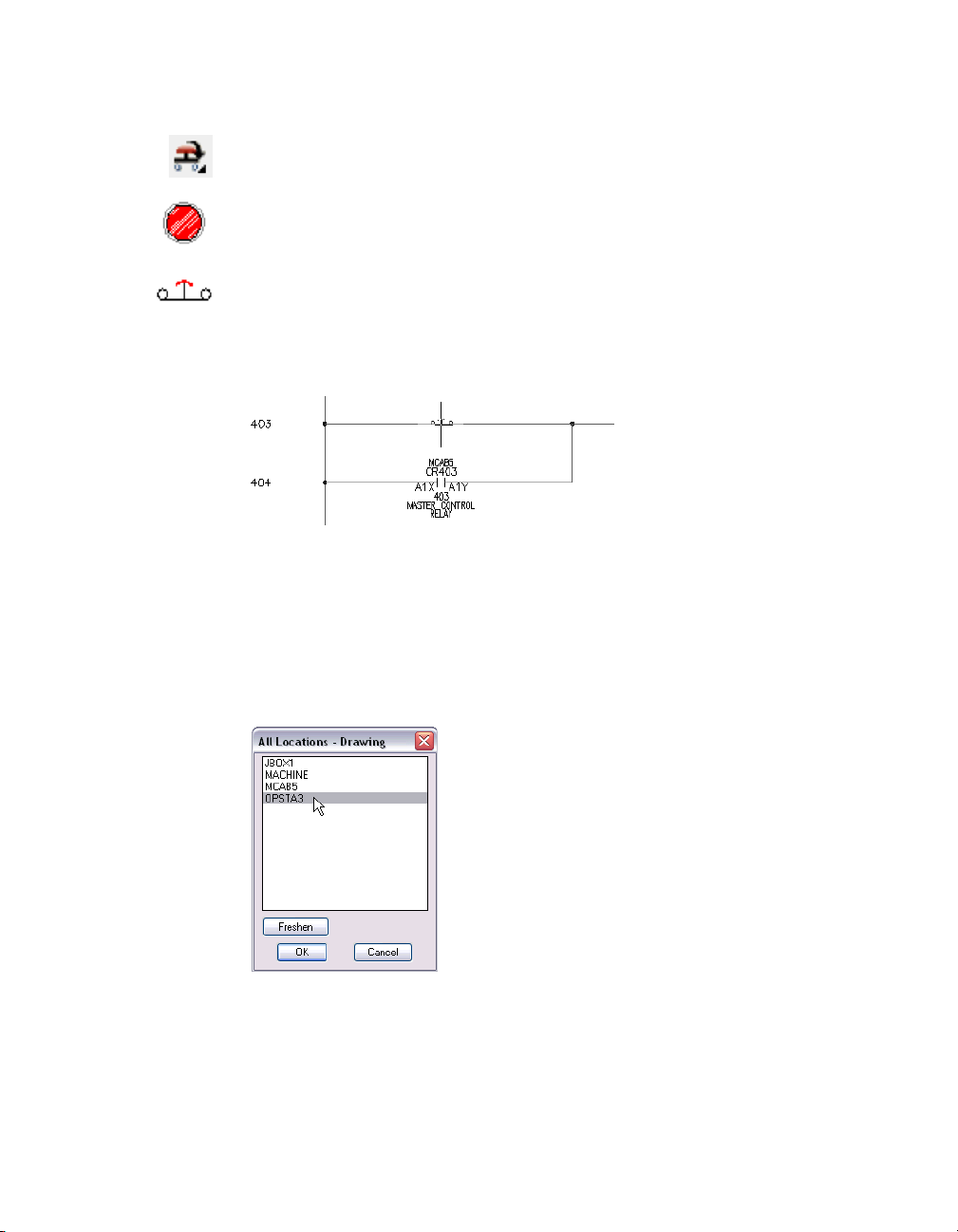
11 In the Insert/Edit Component dialog box, Location code section, click the
Drawing button.
Inserting Components | 13
Page 18
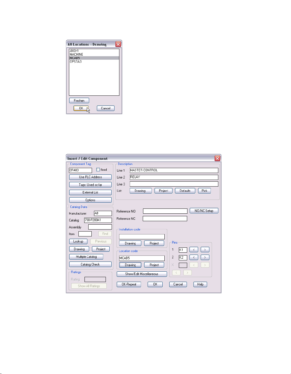
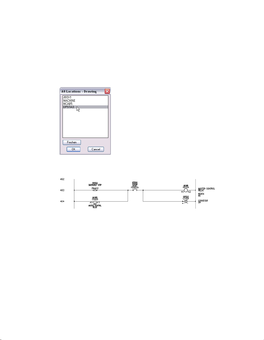
12 In the All Locations - Drawing dialog box, select MCAB5, and then click OK.
13 In the Insert/Edit Component dialog box, Pins section, notice that the
following pin values have been inserted based on the selected part:
Pins: 1: K1
2: K2
Click OK.
Any values entered here are saved as attribute values on the symbol itself.
14 | Chapter 2 Schematic Components
Page 19
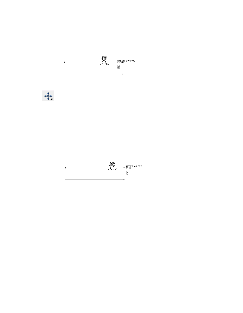
Scooting Components
You may need to scoot the component if it was not inserted in the correct
location.
To scoot a component
1 Click the Scoot tool.
Menu Components ➤ Scoot
2 Respond to the prompts as follows:
Select component, wire, or wire number for SCOOT:
Select the component that was just inserted at line reference 403
The cursor changes to a box and you are prompted to:
Select component, wire, or wire number for SCOOT: to:
Move the cursor to the right and click
The component is now in its new location.
You can use the Scoot tool to grab a component or a wire number and slide
it back and forth along a wire. You can grab a wire or a whole rung of circuitry
and scoot it to a new position, while keeping everything connected.
Inserting Child Components
The steps to insert a parent component and a child component are the same.
The difference between them is when you annotate the symbol.
Inserting Components | 15
Page 20
To insert a child component
1 Click the Insert Component tool.
Menu Components ➤ Insert Component
2 In the Insert Component: JIC Schematic Symbols dialog box, click the Relays
and Contacts button.
3 In the JIC: Relays and Contacts dialog box, click the Relay N.O. Contact
button.
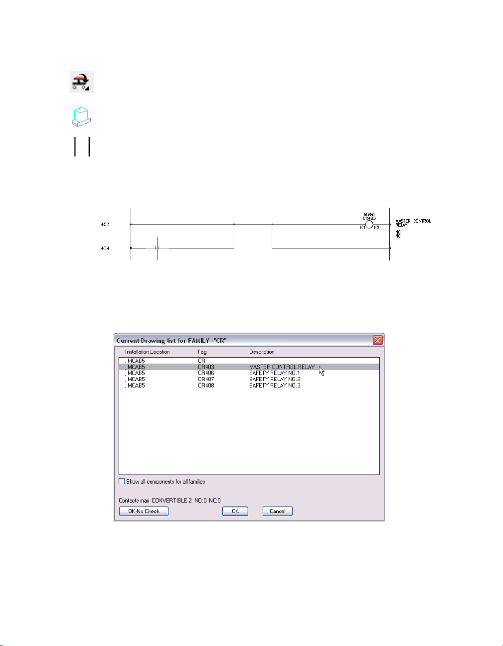
4 Respond to the prompts as follows:
Specify insertion point:
Position the cursor on the wire at line reference 404 near the hot wire and click (2)
2
X
5 In the Insert/Edit Child Component dialog box, Component Tag section,
click the Drawing button.
6 In the Current Drawing list for FAMILY=”CR” dialog box, select:
MCAB5 CR403 MASTER CONTROL RELAY
Click OK.
16 | Chapter 2 Schematic Components
Page 21
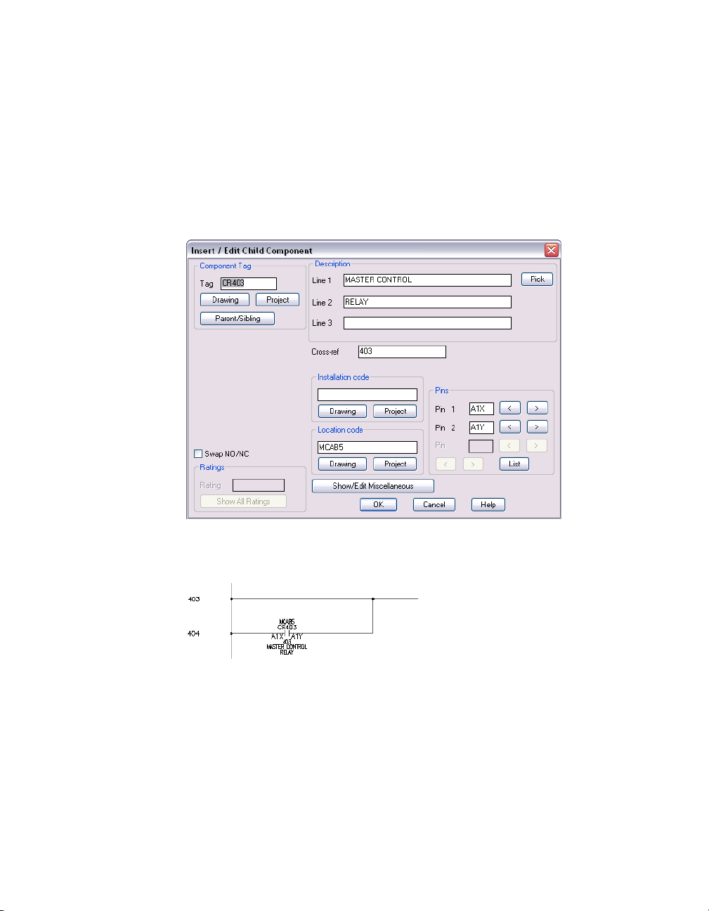
7 In the Insert/Edit Child Component dialog box, verify that the following
options are specified:
Component Tag: Tag: CR403
Description: Line 1: MASTER CONTROL
Line 2: RELAY
Cross-ref: 403
Location code: MCAB5
Pins: Pin 1: A1X
Pin 2: A1Y
Click OK.
The child component is inserted:
If necessary, use Edit Component to modify changes.
Inserting Components | 17
Page 22
Aligning Components
2
Align the normally open relay with an existing component. After inserting a
component, you can align or edit it as necessary.
To align a component.
1 Click the drop-down arrow on the Scoot tool to access the Align Components
tool.
Menu Components ➤ Align
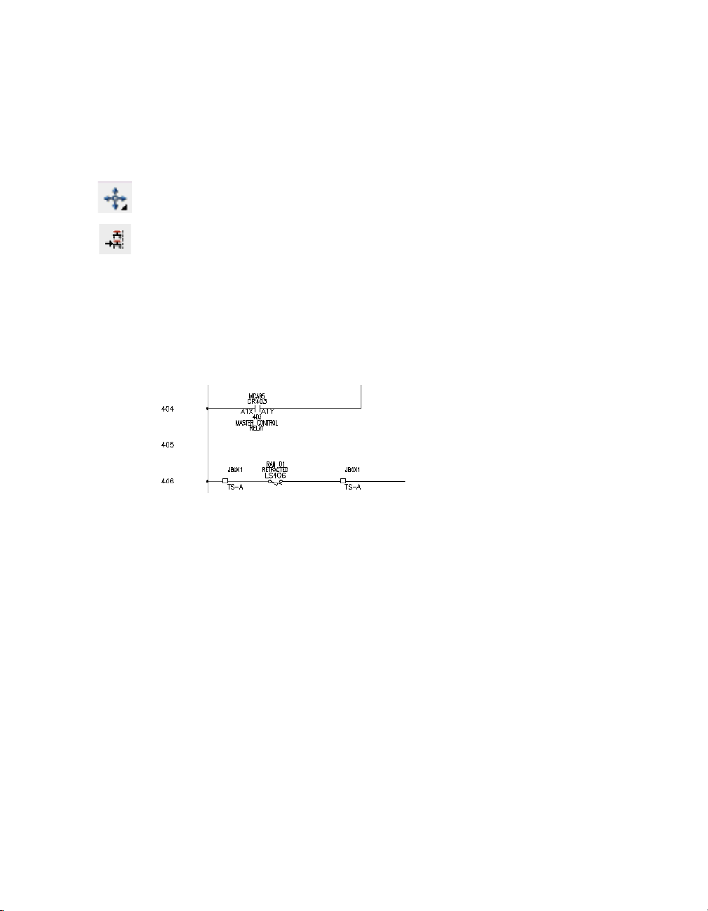
2 Respond to the prompts as follows:
Pick component to align with (Horizontal/<Vertical>): Select the normally open
limit switch component near the hot wire at line reference 406 (1)
A dashed line appears.
Select objects: Select the previously inserted child contact component near the hot
wire at line reference 404 (2)
1
3 Right-click the selection.
The aligned component is placed.
Continue inserting your components.
Inserting Push Buttons
Insert a button for emergency stops.
18 | Chapter 2 Schematic Components
Page 23
To insert a push button
1 Click the Insert Component tool.
Menu Components ➤ Insert Component
2 In the Insert Component: JIC Schematic Symbols dialog box, click the Push
Buttons button.
3 In the JIC: Push Buttons dialog box, click the Mushroom Head N.C. push
button.
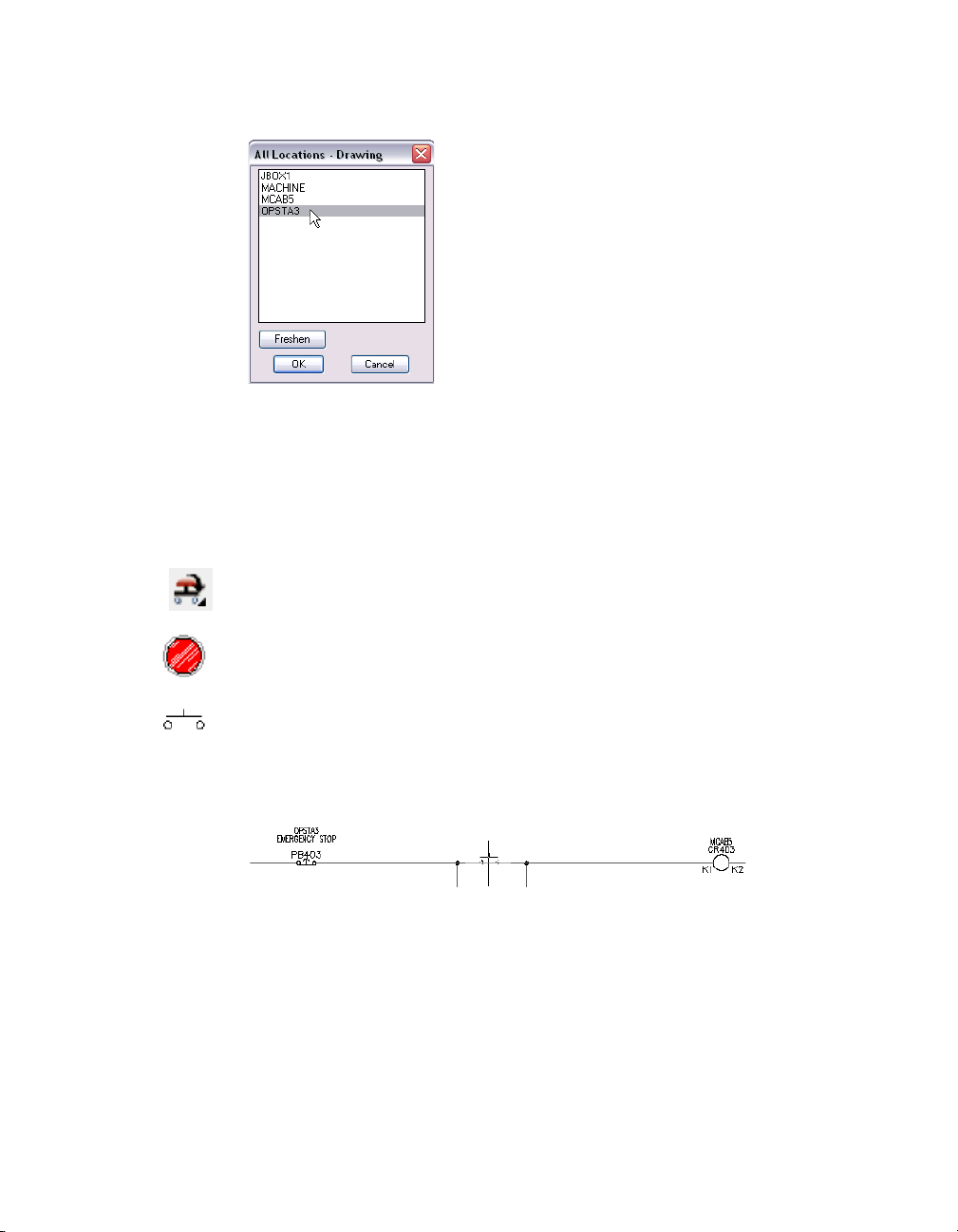
4 Respond to the prompts as follows:
Specify insertion point: Position the push button on the wire at line reference 403
near the hot wire and click (3)
3
5 In the Insert/Edit Component dialog box, verify the following value:
Component Tag: PB403
In the Description section, specify:
Line 1: EMERGENCY STOP
In the Location code section, click the Drawing button.
6 In the All Locations - Drawing dialog box, select OPSTA3, and then click OK.
7 In the Insert/Edit Component dialog box, click OK.
Inserting Components | 19
Page 24
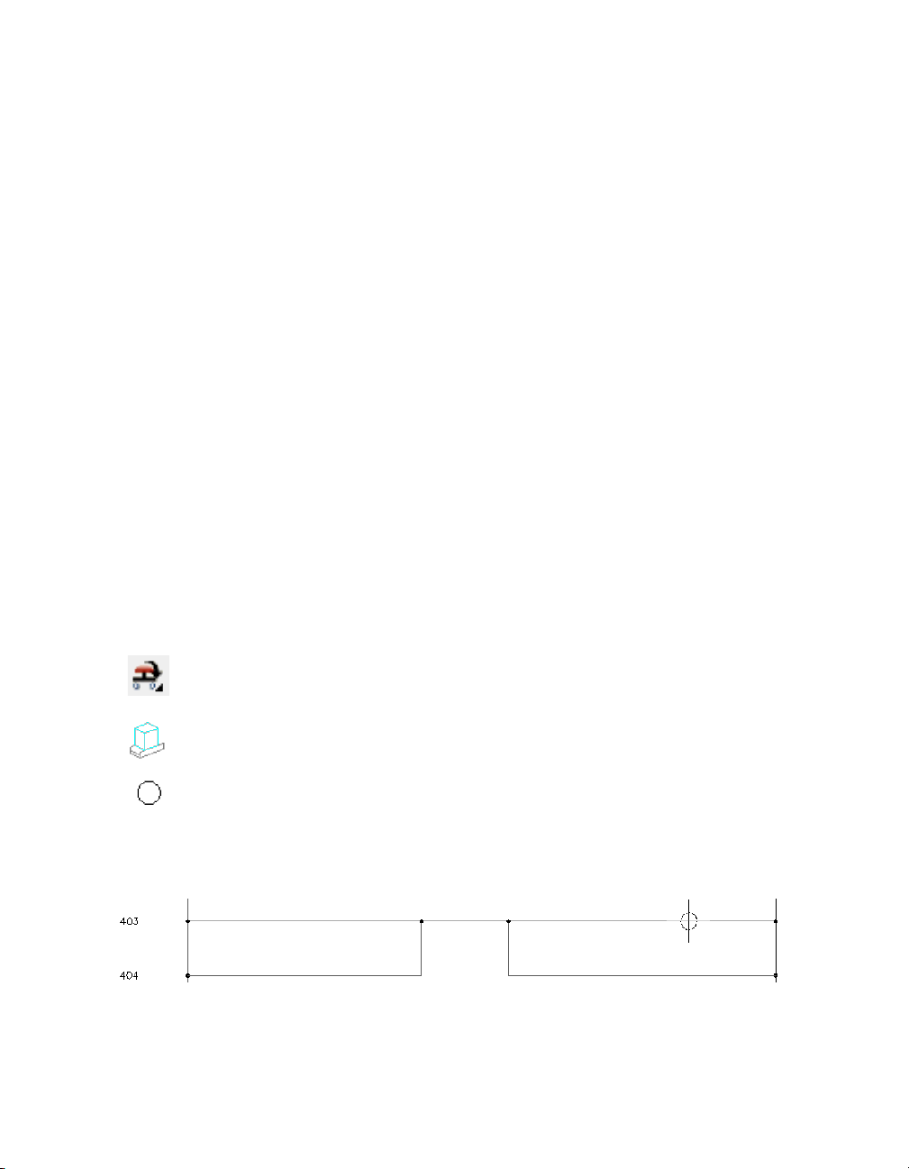
Inserting Pilot Lights
Use the JIC: Pilot Lights dialog box to insert a pilot light.
To insert a pilot light
1 Click the Insert Component tool.
Menu Components ➤ Insert Component
2 In the Insert Component: JIC Schematic Symbols dialog box, click the Pilot
Lights button.
3 In the JIC: Pilot Lights dialog box, click the Green Press to Test Button.
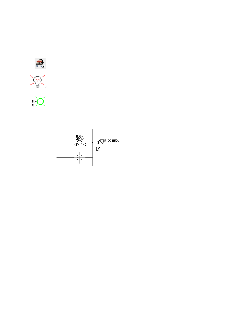
4 Respond to the prompts as follows:
Specify insertion point: Position the push button on the wire at line reference 404
near the neutral wire and click (4)
4
5 In the Insert/Edit Component dialog box, verify the following value:
Component Tag: LT404
In the Description section, specify:
Line 1: CONVEYOR
Line 2: ON
In the Location code section, click the Drawing button.
20 | Chapter 2 Schematic Components
Page 25
6 In the All Locations - Drawing dialog box, select OPSTA3, and then click OK.
7 In the Insert/Edit Component dialog box, click OK.
Inserting System Reset Buttons
The last component you insert is the system reset button.
To insert a system reset button
1 Click the Insert Component tool.
Menu Components ➤ Insert Component
2 In the Insert Component: JIC Schematic Symbols dialog box, click the Push
Buttons button.
3 In the JIC: Push Buttons dialog box, click the Push Button N.O.
4 Respond to the prompts as follows:
Specify insertion point:
Position the push button on the middle of the wire at line reference 403 (5)
5
Inserting Components | 21
Page 26
5 In the Insert/Edit Component dialog box, specify the following value:
Component Tag: PB403A
In the Description section, specify:
Line 1: SYSTEM
Line 2: RESET
In the Location code section, click the Drawing button.
6 In the All Locations - Drawing dialog box, select OPSTA3, and then click OK.
7 Click OK on the Insert/Edit Component dialog box.
Your finished schematic should resemble the following:
22 | Chapter 2 Schematic Components
Page 27
Generating Component Reports
AutoCAD Electrical can perform a project-wide extract of all components
found on your wiring diagram set, including component tags, location
codes, location references, description text, catalog information, and block
names. This data can be formatted into various report configurations that
can be output to a report file, exported to a spreadsheet or database program,
or inserted on to an AutoCAD drawing.
To generate a schematic component report
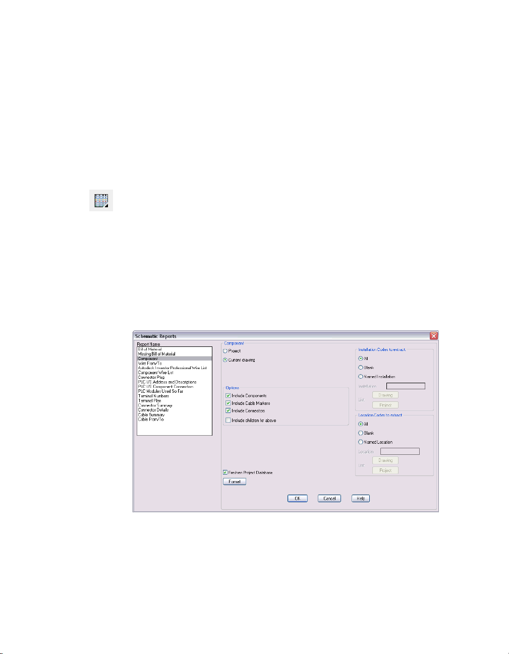
1 Click the Schematic Reports tool.
Menu Projects ➤ Reports ➤ Schematic Reports
2 In the Schematic Reports dialog box, select:
Report Name: Component
Component: Current drawing
Verify that the following options have been specified:
Options: Include Components, Include Cable Markers, Include Connectors
Installation Codes to extract: All
Location Codes to extract: All
Click OK.
Generating Component Reports | 23
Page 28

3 Click OK in the QSAVE dialog box.
The generated report appears in Drawing Schematic Component report for
all locations dialog box.
4 Use this dialog box to incorporate this information into your drawing, save
it to a file, or to print the report.
5 In the Drawing Schematic Component report for all locations dialog box,
click the Close button
This is the end of this tutorial chapter.
24 | Chapter 2 Schematic Components
Page 29

Drawings
In This Chapter
3
An AutoCAD® drawing becomes AutoCAD® Electrical
compatible as soon as you select a AutoCAD Electrical
command to modify your drawing. An invisible block,
WD_M, is automatically inserted right on your drawing.
This block contains a number of attributes that define
many AutoCAD Electrical settings.
■ Working with templates
■ Inserting ladders
■ Inserting 3-phase wiring
■ Adding the current drawing to a
project
■ Adding drawing descriptions
25
Page 30

Working with Templates
In AutoCAD Electrical, you can use templates (*.dwt files) to create drawings.
Predefined templates, which contain settings for various drawings, such as
acad.dwt or ACAD_ELECTRICAL.dwt, are supplied with AutoCAD Electrical.
You can create your own templates, or use any drawing as a template. When
you use a drawing as a template, the settings in that drawing are used in the
new drawing.
Selecting Templates
Use the AutoCAD Electrical template to start a new drawing.
To select a template
1 Select File ➤ New.
2 In the Select template dialog box, select ACAD_ELECTRICAL.dwt, and the
click Open.
26 | Chapter 3 Drawings
Page 31

Inserting Ladders
You can insert a ladder on a drawing at any time. A drawing may have
multiple ladders, as well as single-phase and three-phase ladders. The ladders
do not have to use the same parameters such as rung spacing, number of
rungs, and ladder width.
To insert a single-phase ladder
1 Click the Insert Ladder tool.
Menu Wires ➤ Ladders ➤ Insert Ladder
2 In the Alert dialog box, select Force this drawing’s configuration setting to
match the project settings option, and then click OK.
Your existing drawing format automatically becomes compatible with AutoCAD
Electrical upon insertion of an invisible block, WD_M. Various settings are
stored as invisible attribute values on this block. When you invoke an AutoCAD
Electrical command and it does not find this invisible WD_M block on your
drawing, the command pauses and prompts you for permission to insert the
block automatically.
Inserting Ladders | 27
Page 32

3 In the Insert New Ladder dialog box, specify:
Width: 10.000
Spacing: 1.0000
1st ref: 1001
Length: 20.000
Rungs: 21
Phase: 1 Phase
NOTE Reference 1001 represents Page 10, Reference 01.
Click OK.
28 | Chapter 3 Drawings
Page 33

4 Respond to the prompts as follows:
Specify start position of first rung: Enter 1.5,21, press ENTER
A single phase ladder is inserted in the drawing.
Use the same process to create three-phase ladder.
Inserting Ladders | 29
Page 34

To insert a three-phase ladder
1 Click the Insert Ladder tool.
Menu Wires ➤ Ladders ➤ Insert Ladder
In the Insert New Ladder dialog box, specify:
Phase: 3 Phase Spacing: 0.5000
Spacing: .7500
1st ref: 1022
Index: 1
Click OK.
2 Respond to the prompts as follows:
Specify start position of first rung: Enter 16, 21, press ENTER
Specify approximate position of last reference number (Z=zoom down,
R=realtime pan): Drag down to the bottom of the single-phase ladder, and click
30 | Chapter 3 Drawings
Page 35

The new ladder is placed into the drawing.
Inserting 3-Phase Wires
You can insert vertical or horizontal 3-phase wiring. Three-phase wiring
automatically breaks and reconnects to any underlying components that it
finds in its path. If it crosses any existing wiring, wire-crossing gaps automat
ically insert.
Inserting 3-Phase Wires | 31
-
Page 36

To insert three-phase bus wiring
1 Click the drop-down arrow on the Insert Wire tool to access the Insert 3
Phase Wire tool.
Menu Wires ➤ Insert 3 Phase Wire
2 In the 3-Phase Bus dialog box, verify the following default values are set:
Horizontal: Spacing: 0.7500
Vertical: Spacing: 0.5000
Starting at: component or another bus
Click OK.
3 Respond to the prompts as follows:
Select component or bus for 3 phase wire:
Select the first vertical wire at line reference 1022 and drag across other wires
Select component or bus for 3 phase wire: to:
Click to place the 3 phase wire
32 | Chapter 3 Drawings
Page 37

The three-phase bus is inserted into the drawing:
Adding Drawings to Projects
Select vertical wire
You can add new drawings to your project at any time.
Before you add a new drawing to a project, it must be saved.
Adding Drawings to Projects | 33
Page 38

To s a v e a f i l e
1 Access the Save As command
Menu File ➤ Save As
2 Navigate to the Aegs folder located several directories below Documents and
Settings.
Save in: Aegs
File name: Enter DEMO10.dwg
Click Save.
To add the current drawing to a project
1 Click the Project New/Existing tool.
Menu Projects ➤ Project ➤ Project New/Existing
2 In the Project Aegs dialog box, click the Add Current button.
3 In the Add drawing(s) dialog box, click the One button.
4 In the Add Drawing to Project dialog box, select DEMO10.dwg, and then click
the Open button.
The drawing is added to your project.
34 | Chapter 3 Drawings
Page 39

Adding Drawing Descriptions
Add a description to define the drawing you added to the project.
To add a drawing description
1 In the Project Aegs dialog box, highlight DEMO10.dwg, and then click the
Properties button.
2 In the Properties: Section/Sub-section Codes and Drawing Description dialog
box, Optional description for this drawing section, specify:
Conveyor Line
Click OK.
The description is now added to your drawing.
3 In the Project Aegs dialog box, Project Drawing List section, select the
Description button to view the drawing descriptions.
This is the end of this tutorial chapter.
Adding Drawings to Projects | 35
Page 40

36
Page 41

PLC
In This Chapter
4
Programmable Logic Controller (PLC) modules are built
dynamically when selected from the menu. From a small
set of library symbols, hundreds of PLC modules can be
built on request. This method allows the module to
conform to the underlying ladder rung spacing, so you
can add spacers and break the module at insertion time.
■ About PLC modules
■ Inserting PLC modules
■ Removing ladder rungs
■ Using Fence Insert
37
Page 42

About PLC Modules
AutoCAD® Electrical generates any of hundreds of different PLC I/O modules
on demand, in a variety of different graphical styles, all without a single,
complete I/O module library symbol resident on the system. Modules auto
matically adapt to the underlying ladder rung spacing, whatever that value
might be, and can even be stretched or broken into two or more pieces at
insertion time.
Inserting PLC modules
AutoCAD Electrical builds a PLC I/O module as it is inserted. A PLC module
is selected, the location is picked, and the module is constructed using a
small set of library symbols.
To i n s e r t a P L C m odule
1 Open DEMO10.dwg, if it is not the current drawing.
2 Click the Insert PLC (Parametric) tool.
Menu Components ➤ Insert PLC Modules ➤
Insert PLC (Parametric)
3 In the PLC Parametric Selection dialog box, select:
Allen-Bradley (manufacturer)
1746 (series)
Discrete Input (type)
1746-IA16 (part number)
Graphics Style: 2, Vertical Module
-
38 | Chapter 4 PLC
Page 43

Click OK.
Inserting PLC modules | 39
Page 44

4 Respond to the prompts as follows:
Specify PLC module insert point (Z=zoom down, R=realtime pan): Specify first
wire closer to neutral wire, ensure the X is directly on the horizontal wire (1), click
1
5 In the Module Layout dialog box, verify the following defaults are set:
Spacing: 1.0000
I/O Points: Insert all
Click OK.
40 | Chapter 4 PLC
Page 45

6 In the I/O Point dialog box, specify the following values, and then click OK:
Rack Number: 1
Slot Number: 1
7 In the I/O Address dialog box, specify the beginning address:
Beginning address: I:11/00
NOTE You can also select the beginning address from the Quick picks list.
Click OK.
8 In the I/O Addressing dialog box, click the Decimal button.
Inserting PLC modules | 41
Page 46

The PLC module is inserted into your drawing.
42 | Chapter 4 PLC
Page 47

Removing Ladder Rungs
Use the wire cutters to remove the unused ladder rungs.
To remove ladder rungs
1 Click the Trim Wire tool.
Menu Wires ➤ Trim Wire
2 Respond to the prompts as follows:
Fence/Zext/<Select wire to TRIM>: Enter F, press ENTER
First fence point: Select above the ladder rung at line reference 1018 (1)
First fence point: to:
Drag through the last ladder rung at line reference 1021 (2), click
First fence point: to: to: Right-click the end the trim command
The ladder rungs are removed from your drawing.
1
2
Removing Ladder Rungs | 43
Page 48

Using Multiple Insert Component
You can insert components into wires that are tied to the PLC module. You
can use the Multiple Insert Component tool to insert a string of normally
open limit switches.
To insert a limit switch
1 Click the Multiple Insert Component tool.
Menu Components ➤ Multiple Insert ➤ Multiple Insert (Icon Menu)
2 In the Insert Component: JIC Schematic Symbols dialog box, click the Limit
Switches button.
3 In the JIC: Limit Switches dialog box, select Limit Switch, N.O.
4 Respond to the prompts as follows:
Component Fence, From Point: Select above the wire at line reference 1001 (1)
Component Fence, From Point: to: Drag below the wire at line reference 1003,
click the point (2), right-click to end command
1
2
5 In the Keep dialog box, select Keep this one, Show edit dialog after each, and
then click OK.
6 In the Insert/Edit Component dialog box, verify the following value:
Component Tag: LS1001
44 | Chapter 4 PLC
Page 49

In the Description section, specify:
Line 1: PALLET ENTERING
Line 2: STATION
In the Location code section, specify: MACHINE
Click OK.
NOTE In the Insert/Edit Component dialog box, Component Tag section, you
can use the Use PLC Address button to add the I/O Address as the component tag.
7 In the Keep dialog box, select Keep this one, Show edit dialog after each, and
then click OK.
8 In the Insert/Edit Component dialog box, verify the following values:
Component Tag: LS1002
Location code: MACHINE
In the Description section, specify:
Line 1: PALLET INSIDE
Line 2: STATION
Click OK.
9 In the Keep dialog box, select Keep this one, Show edit dialog after each, and
then click OK.
10 In the Insert/Edit Component dialog box, verify the following values:
Component Tag: LS1003
Location code: MACHINE
In the Description section, specify:
Line 1: PALLET LEAVING
Line 2: STATION
Click OK.
The normally open limit switches are inserted into the drawing.
Using Multiple Insert Component | 45
Page 50

To insert terminals
1 Click the Multiple Insert Component tool.
Menu Components ➤ Multiple Insert ➤ Multiple Insert (Icon Menu)
2 In the Insert Component: JIC Schematic Symbols dialog box, click the
Terminals/Connectors button.
3 In the JIC: Terminals and Connectors dialog box, click the Round with
Terminal Number button.
4 Respond to the prompts as follows:
Component Fence, From Point: Select above wire at line reference 1001 (1)
Component Fence, From Point: to: Select below wire at line reference 1016 (2),
left click to end command, and then right-click to add terminal
1
5 In the Keep dialog box, select Keep this one, Show edit dialog after each, and
then click OK.
46 | Chapter 4 PLC
2
Page 51

6 In the Terminals dialog box, specify:
Tag-ID: TS1
Terminal Number: 1
Location code: MCAB
Click OK.
7 In the Keep dialog box, select Keep all, don’t ask, unselect Show edit dialog
after each, and then click OK.
Using Multiple Insert Component | 47
Page 52

The terminals are automatically added to your drawing.
This is the end of this tutorial chapter.
48 | Chapter 4 PLC
Page 53

Wire Numbers
In This Chapter
5
Wire numbers can be assigned to any and all existing
wires on an individual selection, an entire drawing,
selected drawings in a project, or an entire project.
■ About wire numbers
■ Attaching source signal arrows
■ Attaching destination signal
arrows
■ Inserting wire numbers
■ Deleting wire numbers
49
Page 54

About Wire Numbers
AutoCAD® Electrical assigns a unique wire number to each wire network. A
wire network consists of one or more wires that are electrically connected.
Attaching Source Signal Arrows
You can attach a source signal to a wire segment of a wire network. This
enables the wire number assigned to the network to jump and continue to
another network on the current drawing or on one or more project drawings.
To attach a source signal arrow
1 Click the Project New/Existing tool.
Menu Projects ➤ Project ➤ Project New/Existing
2 Double-click demo03.dwg to open drawing.
3 In the Drawing Modification dialog box, click the Save Changes button to
save the changes to the current drawing.
4 Click the drop-down arrow on the Source Destination Signals tool to access
the Source Signal Arrow tool.
Menu Wires ➤ Signal References ➤ Source Signal Arrow
50 | Chapter 5 Wire Numbers
Page 55

5 Respond to the prompts as follows:
Select wire end for Source: Select the end of the hot wire on the schematic on
the right side of the drawing at line reference 332 (1)
1
6 In the Signal - Source Code dialog box, specify:
Code: 24 VDC
Click OK.
Attaching Source Signal Arrows | 51
Page 56

7 In the Source/Destination Signal Arrows dialog box, click No.
NOTE Click No to insert the signal arrows on the next drawing. Click OK to
insert the signal arrows on the current drawing.
8 Click the Next Project Drawing tool to access demo04.dwg.
Now you are ready to insert a destination signal arrow.
Attaching Destination Signal Arrows
Once the source signal arrow is attached to the drawing, you can then attach
a destination signal to a wire segment of a wire network. This enables the
wire number assigned to another source wire network to automatically carry
over to the current network.
To attach a destination signal
1 Click the drop-down arrow on the Source Destination Signals tool to access
the Destination Signal Arrow tool.
Menu Wires ➤ Signal References ➤ Destination Signal Arrow
2 Respond to the prompt as follows:
Select wire end for Destination: Select the top of the hot wire on the schematic
on the left side of the drawing at line reference 402 (2)
2
52 | Chapter 5 Wire Numbers
Page 57

3 In the Insert Destination Code dialog box, click the Project button.
4 In the Signal codes -- Project-wide SOURCE dialog box, select the following:
Click OK.
5 In the Insert Destination Code dialog box, verify the following value:
Code: 24 VDC
6 Click the OK + Update Source button.
Attaching Destination Signal Arrows | 53
Page 58

Notice the cross-references for your signal are inserted into the drawing
above the hot wire.
Use the same procedure to attach source and destination signals to the neutral
wires.
1 Click the Previous Project Drawing button to return to demo03.dwg.
2 Click the drop-down arrow on the Source Destination Signals tool to access
the Source Signal Arrow tool.
Menu Wires ➤ Signal References ➤ Source Signal Arrow
3 Respond to the prompts as follows:
Select wire end for Source:
Select the bottom of the neutral wire at line reference 332 (3)
54 | Chapter 5 Wire Numbers
3
Page 59

4 In the Signal - Source Code dialog box, specify:
Code: 24 VDC NEUTRAL
Click OK.
5 In the Source/Destination Signal Arrows dialog box, click No.
NOTE Click No to insert the signal arrows on the next drawing. Click OK to
insert the signal arrows on the current drawing.
6 Click the Next Project Drawing tool to access demo04.dwg.
7 Click the drop-down arrow on the Source Destination Signals tool to access
the Destination Signal Arrow tool.
Menu Wires ➤ Signal References ➤ Destination Signal Arrow
8 Respond to the prompt as follows:
Select wire end for Destination:
Select the top of the neutral wire at line reference 402 (4)
4
Attaching Destination Signal Arrows | 55
Page 60

9 In the Insert Destination Code dialog box, click the Project button.
10 In the Signal codes -- Project-wide SOURCE dialog box, select the following
option:
Click OK.
56 | Chapter 5 Wire Numbers
Page 61

11 In the Insert Destination Code dialog box, verify the following value:
Code: 24 VDC NEUTRAL
12 Click the OK + Update Source button.
Notice the cross-references for your signal are inserted into the drawing
above the neutral wire.
Now you can view the new signals.
Attaching Destination Signal Arrows | 57
Page 62
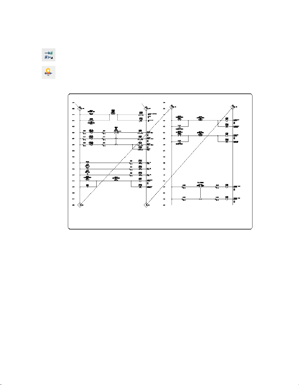
To view signals
1 Click the drop-down arrow on the Source Destination Signals tool to access
the Show Signal Path tool.
Menu Wires ➤ Signal References ➤ Show Signal Paths
Temporary graphics are used to illustrate the flow of the signals on your
drawings.
Inserting Wire Numbers
You can process and tag wires with sequential wire numbers or with wire
numbers based upon the line reference location of the wire network. When
wire numbers are automatically inserted into a drawing, the numbers will
not be duplicated if they are defined on another network.
AutoCAD Electrical works from left to right, top to bottom as it processes wire
networks.
58 | Chapter 5 Wire Numbers
Page 63

To insert wire numbers automatically
1 Verify that demo04.dwg is the current drawing.
2 Zoom the top portion of the wire network on the left side of the drawing.
3 Click the Automatic Wire Numbers tool.
Menu Wires ➤ Automatic Wire Numbers
4 In the Sheet 4 - Wire Tagging dialog box, click the Pick Individual Wires button.
5 Respond to the prompts as follows:
Select objects: Select the wire segment between the two push buttons on line
reference 403 (1), right-click
1
The wire number is placed.
To add wire numbers to the entire drawing
1 Click the Automatic Wire Numbers tool.
Menu Wires ➤ Automatic Wire Numbers
2 In the Sheet 4 - Wire Tagging dialog box, click the Drawing-wide button.
Wire numbers are assigned to each segment in your drawing.
Inserting Wire Numbers | 59
Page 64

To add wire numbers project wide
1 Click the Automatic Wire Numbers tool.
Menu Wires ➤ Automatic Wire Numbers
2 In the Sheet 4 - Wire Tagging dialog box, click the Project-wide button.
3 In the Wire tagging (Project-wide) dialog box, verify the following settings:
Wire tag mode: Reference-based tags
To d o : Tag/retag all
Freshen database (for Signals)
Click OK.
60 | Chapter 5 Wire Numbers
Page 65

4 In the Wire Tagging: Select drawings to process dialog box, Project Drawing
List section, hold the SHIFT key and select demo03.dwg and demo04.dwg, and
then click the Process v button.
5 Verify the selected drawings are listed in the Drawings to Process section of
the Wire Tagging: Select drawings to process dialog box: demo03.dwg and
demo04.
Click OK.
6 In the Create Zip back-up? dialog box, click the No backup button.
7 Click OK in the QSAVE dialog box.
Wire numbers are processed for the selected drawings.
Deleting Wire Numbers
You can use the Delete Wire Numbers tool to select a wire number or to pick
on any wire of the network.
To delete a wire number
1 Click the Delete Wire Number tool.
Menu Wires ➤ Delete Wire Number
2 Respond the prompt as follows:
Select objects: Enter all, press ENTER
The wires in the network change to dashed lines, represented the wires from
which the wire numbers will be erased.
3 Press ENTER again to erase the wire numbers.
This is the end of this tutorial chapter.
Deleting Wire Numbers | 61
Page 66

62
Page 67
Panel Layouts
In This Chapter
6
AutoCAD® Electrical provides tools to create intelligent
panel layout drawings. Layouts can be driven from
information carried on the AutoCAD Electrical
schematic drawings or they can be constructed
independently of the schematics.
■ About panel layouts
■ Inserting panel components
■ Modifying attributes
■ Inserting footprints
63
Page 68

About Panel Layouts
AutoCAD Electrical places no requirements on special naming or attribute
requirements on mechanical footprint symbols. This means that vendor
supplied footprint symbols, in AutoCAD format, can be used as is with
AutoCAD Electrical.
Inserting Panel Components
Using the AutoCAD Electrical Panel Layout tools, you can select from a list
of schematic components and then place the footprint component directly
into a panel layout. Once placed, the footprint remains linked to the original
schematic components. This allows for bidirectional updating between
schematic components and the associated footprint blocks.
For this exercise, use the Panel Layout tools:
You are now ready to select the components to insert on the panel layout.
To select schematic component footprints
1 Click the Project New/Existing tool.
Menu Projects ➤ Project ➤ Project New/Existing
2 Double-click demo08.dwg to open the Operator Station Layout drawing.
3 In the Drawing Modification dialog box, click the Save Changes button.
64 | Chapter 6 Panel Layouts
Page 69

4 Click the drop-down arrow on the Insert Footprint tool to access the Insert
Footprint (Schematic List) tool.
Menu Panel Layout ➤ Insert Footprint (Schematic List)
5 In the Schematic Component List Panel Layout Insert dialog box, verify the
following settings, and then click OK.
Extract component list for: Project
Location Codes to extract: All
Click OK.
6 In the Schematic Components Panel Layout list: select drawings to process
dialog box, select demo04.dwg.
7 Click the Process v button, verify demo04.dwg appears in the Drawing to
Process section of the dialog box, and then click OK.
Inserting Panel Components | 65
Page 70
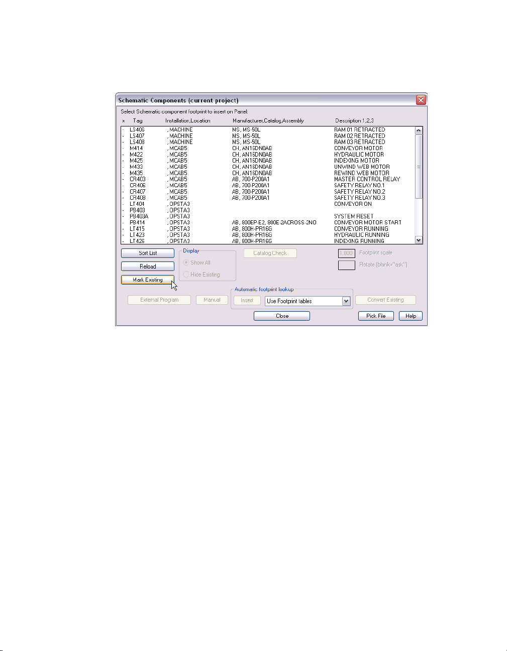
8 In the Schematic Components (current project) dialog box, click the Mark
Existing button. An x marks the components that have already been placed
in the project.
66 | Chapter 6 Panel Layouts
Page 71
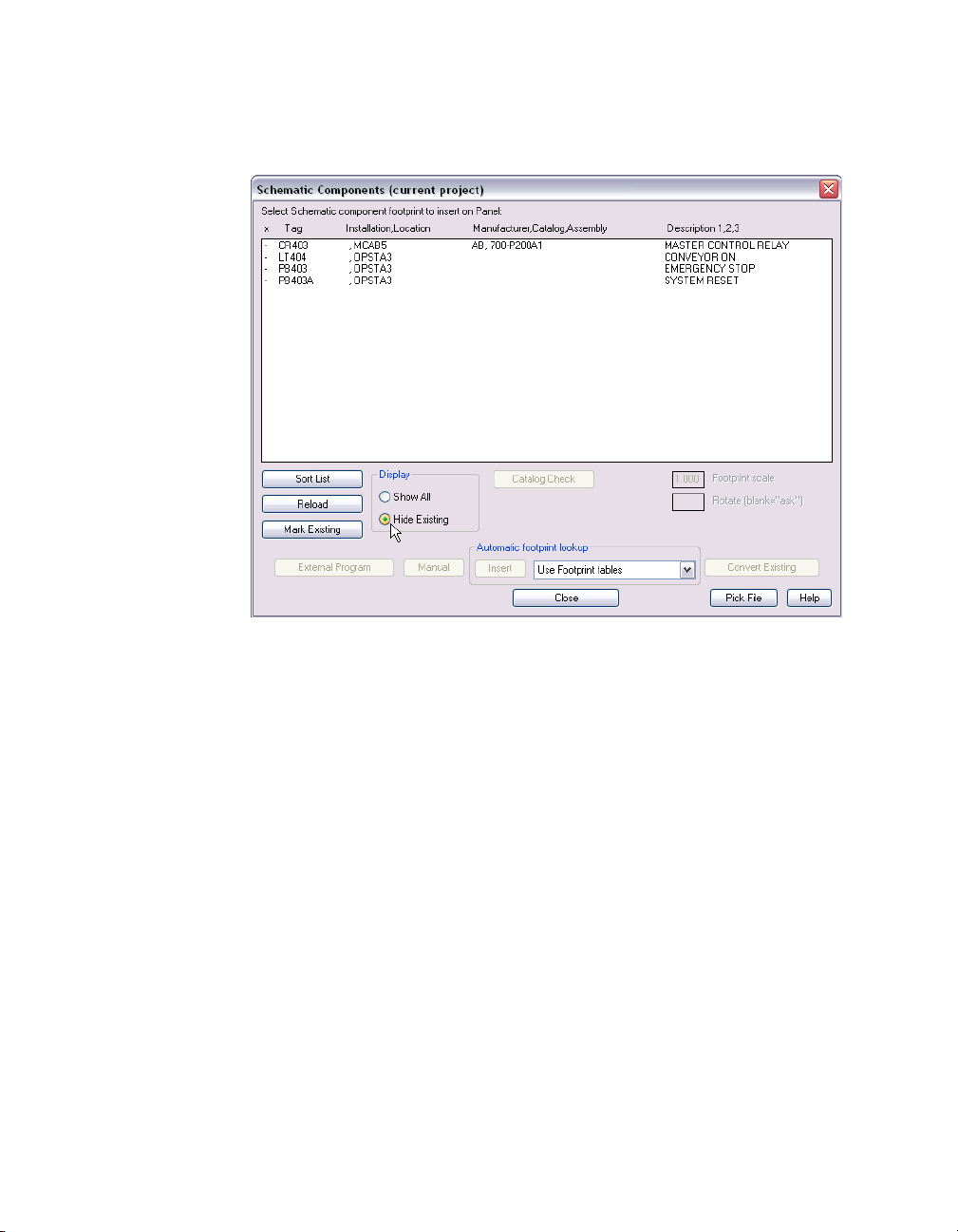
9 In the Schematic Components (current project) dialog box, Display section,
select the Hide Existing radio button to display the schematic component
footprints to be inserted into the panel layout.
You are now ready to begin manually inserting schematic component
footprints on the panel layout.
Inserting Panel Components | 67
Page 72

To manually insert the emergency stop footprint
1 In the Schematic Components (current project) dialog box, select:
PB403 OPSTA3 EMERGENCY STOP, and then click the Manual button.
NOTE The Manual button is used when schematic component footprints do
not have a manufacturer and catalog number defined.
Next, you need to define a catalog assignment for an automatic footprint
selection.
68 | Chapter 6 Panel Layouts
Page 73

To make a catalog assignment
1 In the Footprint dialog box, Choice A section, click the Catalog lookup
button.
NOTE Use Choice B to enter a graphic without selecting a catalog number.
2 In the Parts Catalog dialog box, select:
CATALOG, CONTACTS, DESCRIPTION 800T-D6A 1NO-1NC PUSH
BUTTON-MUSHROOM, NEMA 4/13
Click OK.
3 In the Footprint dialog box, Choice A section, verify the following values:
Manufacturer AB
Catalog 800T-D6A
Click OK.
Inserting Panel Components | 69
Page 74

4 Respond to the prompts as follows:
Select Location for PB403: Select to the left of PB414A (1)
Select Location for PB403: <Ortho on> select ROTATION:
Right-click to place the push button
1
5 In the Panel Layout - Component Insert/Edit dialog box, click OK.
70 | Chapter 6 Panel Layouts
Page 75

NOTE The Panel Layout - Component Insert/Edit dialog box is displayed each
time you insert a panel footprint. Information from the schematic representation
is automatically carried over to the panel footprint representation.
Now you’re ready to insert the system reset button on the panel layout.
To manually insert the system reset footprint
1 In the Schematics Components (current project) dialog box, select:
PB403A
OPSTA3 SYSTEM RESET, and then click the Manual button.
2 In the Footprint dialog box, Choice A section, click the Catalog lookup
button.
Inserting Panel Components | 71
Page 76

3 In the Parts Catalog dialog box, select:
MANUFACTURER AB
TYPE 30.5mm FLUSH
STYLE *ALL*
CATALOG, CONTACTS, STYLE, DESCRIPTION 800T-A2A
1 NO 1 NC BLACK PUSH BUTTON - MOMENTARY, NEMA 4/13
Click OK.
4 In the Footprint dialog box, Choice A section, verify the following values:
Manufacturer AB
Catalog 800T-A2A
Click OK.
5 Respond to the prompts as follows:
Select Location for PB403A: Select to the left of Conveyor Motor Start (2)
Select Location for PB403A: <Ortho on> select ROTATION:
Right-click to place the push button
72 | Chapter 6 Panel Layouts
Page 77

2
6 In the Panel Layout - Component Insert/Edit dialog box, click OK.
NOTE The Panel Layout - Component Insert/Edit dialog box is displayed each
time you insert a panel footprint. Information from the schematic representation
is automatically carried over to the panel footprint representation.
Now you’re ready to insert conveyor on light.
Inserting Panel Components | 73
Page 78

To manually insert the light footprint
1 In the Schematic Components (current project) dialog box, select
LT404 OPTSTA3 CONVEYOR ON, and then click the Manual button.
2 In the Footprint dialog box, Choice A section, click the Catalog lookup
button.
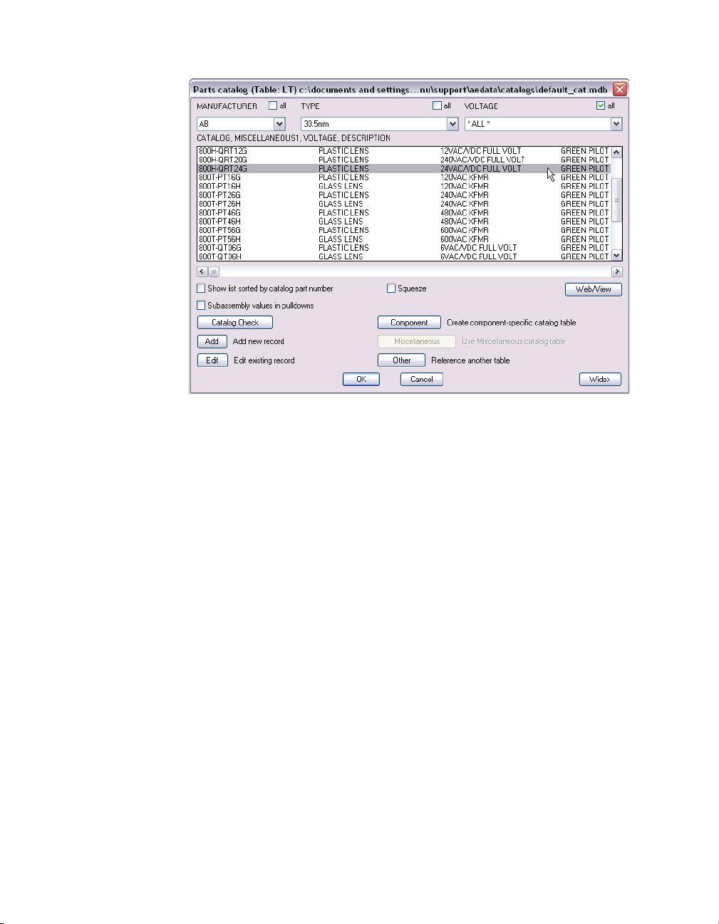
3 In the Parts Catalog dialog box, select:
MANUFACTURER AB
TYPE 30.5mm
VOLTAGE *ALL*
CATALOG, MISCELLANEOUS1, VOLTAGE, DESCRIPTION
800H-QRT24G PLASTIC LENS 24VAC/VDC FULL VOLT GREEN PILOT
NOTE To easily sort the Catalog list, select the Show list sorted by catalog part
number on the Parts catalog dialog box.
74 | Chapter 6 Panel Layouts
Page 79
Click OK.
4 In the Footprint dialog box, Choice A section, verify the following values:
Manufacturer AB
Catalog 800H-QRT24G
Click OK.
Inserting Panel Components | 75
Page 80

5 Respond to the prompts as follows:
Select Location for LT404: Select to the left of the conveyor running light (3)
Select Location for LT404: <Ortho on> select ROTATION:
Right-click to place the push button
3
6 In the Panel Layout - Component Insert/Edit dialog box, click OK.
76 | Chapter 6 Panel Layouts
Page 81

7 In the Schematics Components (current project) dialog box, notice the
master control relay still needs to be placed.
8 Click the Close button.
Modifying Attributes
You can align the inserted schematic component footprints with existing
footprints.
To align footprints vertically
1 Click the drop-down arrow on the Scoot tool to access the Align tool.
Menu Components ➤ Align
2 Respond to the prompts as follows:
Select component to align with (Horizontal/<Vertical>): Enter V, press ENTER
Select component to align with (Horizontal/<Vertical>):
Select the power on button on the top, left of the layout (1)
Select objects:
Select the three components that were just inserted (2-4), right-click
1
2
3
4
The components are aligned vertically.
Use the same procedure to align the schematic component footprints
horizontally.
Modifying Attributes | 77
Page 82

To align footprints horizontally
1 Click the Align tool.
Menu Components ➤ Align
2 Respond to the prompts as follows:
Select component to align with (Horizontal/<Vertical>): Enter H, press ENTER
Select component to align with (Horizontal/<Vertical>):
Select the conveyor running button (1)
Select objects: Select LT404 (2), right click to align horizontally
2
1
3 Follow steps 1 and 2 to align the remaining footprints.
You can also move component attributes.
To move an attribute
1 Click the Move/Show Attribute tool.
Menu Components ➤ Attributes ➤ Move/Show Attribute
2 Respond to the prompts as follows:
Select attribute to Move or pick on block graphics for list (W=Window move):
Select LT404 (1)
Select object: Right-click to select
Base point: Select the base point, drag to the new location (2), right-click
21
The attribute is placed.
78 | Chapter 6 Panel Layouts
Page 83

Inserting Nameplate Footprints
You are now ready to add nameplates to the panel layout.
To insert an automotive type name plate
1 Click the Insert Footprint tool.
Menu Panel Layout ➤ Insert Footprint (Icon Menu)
2 In the Insert Footprint: Panel Layout Symbols dialog box, click the
Nameplates button.
3 In the Panel: Nameplates dialog box, click the Nameplate, Catalog Lookup
button.
4 In Nameplate dialog box, Choice A section, click the Catalog lookup button.
5 In the Parts Catalog dialog box, select:
MANUFACTURER AB
TYPE 800T Automotive
COLOR_AND_ *ALL*
CATALOG, MISCELLANEOUS1, MISCELLANEOUS2, COLOR_AND_,
DESCRIPTION 800T-X701 Red Blank Name Plate
Click OK.
Inserting Nameplate Footprints | 79
Page 84

6 In the Nameplate dialog box, Choice A section, verify the following values:
Manufacturer AB
Catalog 800T-X701
Click OK.
7 Respond to the prompts as follows:
Select objects: Select PB403 (1), right-click to the place the nameplate
1
8 In the Panel Layout - Nameplate Insert/Edit dialog box, click OK to insert the
nameplate.
To insert a half round nameplate
1 Click the Insert Footprint tool.
Menu Panel Layout ➤ Insert Footprint (Icon Menu)
2 In the Insert Footprint: Panel Layout Symbols dialog box, click the
Nameplates button.
3 In the Panel: Nameplates dialog box, click the Nameplate, Catalog Lookup
button.
4 In the Nameplate dialog box, Choice A section, click the Catalog lookup
button.
80 | Chapter 6 Panel Layouts
Page 85
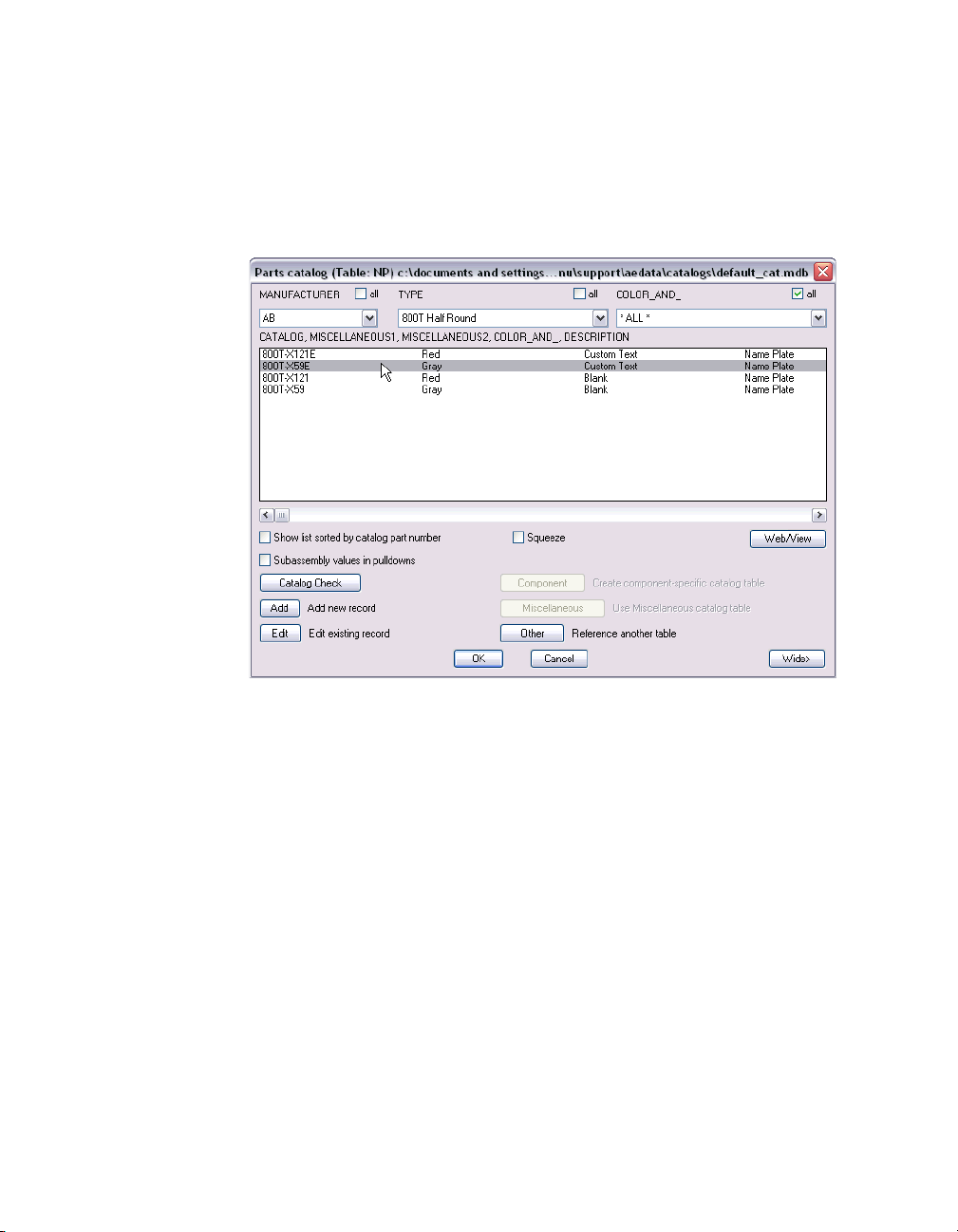
5 In the Parts Catalog dialog box, select:
MANUFACTURER AB
TYPE 800T Half Round
COLOR_AND_ *ALL*
CATALOG, MISCELLANEOUS1, MISCELLANEOUS2, COLOR_AND_,
DESCRIPTION 800T-X59E Gray Custom Text Name Plate
Click OK.
6 In the Footprint dialog box, Choice A section, verify the following values:
Manufacturer AB
Catalog 800T-X59E
Click OK.
Inserting Nameplate Footprints | 81
Page 86

7 Respond to the prompts as follows:
Select objects: Select PB403A (2), right-click to place the nameplate
2
8 In the Panel Layout - Nameplate Insert/Edit dialog box, click OK to insert the
nameplate.
The nameplate is inserted.
This is the end of this tutorial chapter.
82 | Chapter 6 Panel Layouts
Page 87

Index
3-Phase Bus dialog box, 32
A
Add Drawings dialog box, 4
Alert dialog box
align components
All Locations-Drawing dialog box
All Locations-drawing dialog box
AutoCAD Electrical Help
, 27
, 18
, 14
, 22
, 2
B
Browse for Folder dialog box, 4
C
catalog assignments, 69
component fence
component reports
components
aligning
child
parent
scooting
Create New Project File dialog box
Current Drawing List for Family="CR" dialog
, 16
, 12
box
, 44
, 23
, 18
, 15
, 3
, 16
D
destination signals, 52
dialog boxes
3-Phase Bus
Add Drawings
, 32
, 4
dialog boxes (continued)
drawing descriptions
Drawing Extract for All Locations dialog box
Drawing Modification dialog box
drawings
, 27
Alert
All Locations-Drawing
All Locations-drawing
Browse for Folder
Create New Project File
Current Drawing List for FAMILY="CR"
Drawing Extract for All Locations
Drawing Modification
I/O Address
I/O Addressing
I/O Point
Insert New Ladder
Insert/Edit Component
Insert/Edit Contact
Keep
Module Layout
Panel Layout-Component Insert/Edit
Parts Catalog
PLC I/O Module Selection/Insert
Qsave
Schematic Component Report
Schematic Components
Select Template
Sheet 4-Insert Destination Code
Signal Codes-Proj-wide Source
Signal-Source Code
Source/Destination Signal Arrows
Ter min als
, 41
, 41
, 44, 46, 47
, 13
, 24
, 47
, 14, 19, 21
, 22
, 4
, 3
, 24
, 64
, 41
, 28, 30
, 14
, 17
, 40
, 38
, 23
, 66
, 26
, 53, 56
, 53
, 51
, 52, 55
, 35
, 64
in projects
viewing within a project
, 4, 34
, 5
, 70
, 16
, 24
Index | 83
Page 88

E
exercises
prerequisites
setting up for
, 2
, 3
F
footprints
aligning horizontally
aligning vertically
manual insertion
, 78
, 77
, 68
H
Help systems, AutoCAD Electrical, 2
I
I/O Address dialog box, 41
I/O Addressing dialog box
I/O Point dialog box
Insert New Ladder dialog box
Insert/Edit Component dialog box
Insert/Edit Contact dialog box
, 41
, 41
, 28, 30
, 14
, 17
K
Keep dialog box, 44, 46, 47
L
ladder rungs, removing, 43
ladders
single-phase
three-phase
, 27
, 30
Q
Qsave dialog box, 24
R
reports, 23
S
Schematic Component Report dialog box, 23
schematic component reports
Schematic Components dialog box
schematic symbols
green press to test pilot light
limit switch button
normally open limit switch
normally open push button
normally open relay
pilot lights
push buttons
relays button
standard coil
terms and connectors
scooting components
Select Template dialog boxes
Sheet 4-Insert Destination Code dialog box
Signal Codes-Proj-wide Source dialog box
signals
destination
source
Signal-Source Code dialog box
source signals
Source/Destination Signal Arrows dialog box
, 20
, 19, 21
, 12, 16
, 12
, 15
56
, 52
, 50
, 50
52, 55
, 23
, 66
, 20
, 44
, 44
, 21
, 16
, 46
, 26
, 53,
, 53
, 51
,
M
Module Layout dialog box, 40
N
name plates, 78
P
Panel Layout-Component Insert/Edit dialog
Parts Catalog dialog box
PLC I/O Module Selection/Insert dialog box
PLC modules
prerequisites for exercises
projects for exercises
84 | Index
box
, 70
, 13
, 38
, 2
, 3
, 38
T
Terminals dialog box, 47
terms and connectors
three-phase bus wiring
, 46
, 32
W
wire numbers, 59
automatic
deleting
projects
wires
single-phase
three-phase bus
trimming
, 59
, 61
, 60
, 8
, 32
, 10
 Loading...