

Page 1
Get wired.
AutoCAD
®
Electrical
Page 2

The AutoCAD Electrical Advantage
To succeed in today’s global marketplace, electrical controls
designers can no longer aord to rely on generic software
applications to get the job done. AutoCAD Electrical oers
control engineers a competitive edge by helping save hours of
eort, so they can spend more time innovating.
Contents
Error Checking and Prevention ..................3
Standards-Based Drafting
and Component Libraries ........................... 4
Design and Drafting
Productivity Tools .........................................5
Schematic Design Tools ............................. 8
Panel Layout Tools ..................................... 10
Programmable Logic Controller Tools .....11
Comprehensive Terminal
Management................................................. 12
Collaboration and Interoperability ......... 13
Data Management
and Reporting Tools ...................................14
Data Migration Tools .................................. 15
Learn More or Purchase ............................16
AutoCAD® Electrical is AutoCAD® software for
controls designers, purpose-built to create and
modify electrical control systems. It contains all the
functionality of AutoCAD, the world’s leading CAD
software, plus a comprehensive set of electricalspecific features and functions that oer significant
productivity gains.
Feature AutoCAD
Full AutoCAD Functionality
Familiar AutoCAD Interface
Powerful Drafting Tools
AutoCAD Electrical helps you stay ahead of the
competition by automating control engineering
tasks, such as building circuits, numbering wires,
and creating bills of material. AutoCAD Electrical
provides a library of more than 650,000 electrical
symbols and components, includes real-time error
checking, and enables electrical and mechanical
teams to collaborate on digital prototypes built
with Autodesk
Autodesk solution for Digital Prototyping, AutoCAD
Electrical helps manufacturers get their products to
market faster with lower costs.
®
Inventor® software. As part of the
®
AutoCAD® Electrical
• •
• •
• •
DWG™ Compatibility
Comprehensive Symbol Libraries
Electrical-Specific Drafting Features
Real-time Error Checking
Schematic Design Tools
Panel Layout Tools
Terminal Management Tools
PLC I/O Tools
Automatic BOM Generation
Autodesk® Inventor® Associativity
2
• •
•
•
•
•
•
•
•
•
•
Page 3
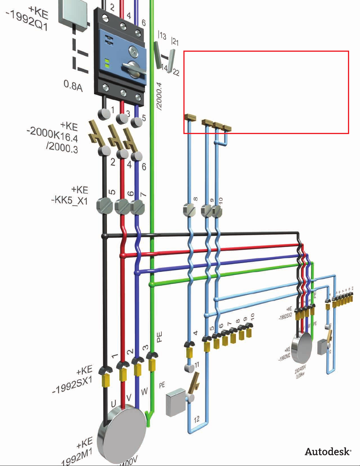
Error Checking and Prevention
AutoCAD
®
Electrical software includes automatic errorchecking capabilities that help designers perform real-time
diagnostics to catch problems before the build phase of a
project.
Automatic Wire Numbering and
Component Tagging
Spending long hours manually assigning wire
numbers and component tags is a thing of the past,
as are the potential errors inherent in that process.
AutoCAD Electrical drafting software automatically
places sequential or reference-based numbers on
all wires and components, based on the configuration you choose. Reference-based numbers and tags
automatically get a sux when necessary so that
names are unique and the software can renumber
the entities as the design requirements change. This
numbering convention is flexible enough to meet
nearly any design requirement.
In addition, if AutoCAD Electrical determines that
an inserted wire number will “bump into” something, it automatically searches laterally along the
wire for a clear spot to place the wire number. If
that fails, it searches for a clear spot away from the
wire. When it finds one, it places the number and
automatically draws a leader back to the wire.
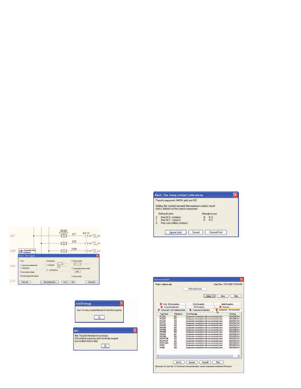
Real-Time Coil and Contact Cross-Referencing
Significantly reduce the risk of costly mistakes associated with assigning too many contacts to a relay.
AutoCAD Electrical sets up a parent/child relationship between the two and keeps track of how many
contacts are assigned to any given coil or multicontact device. When you exceed the limit, you get
an alert.
Another benefit of this feature is the ability to assign
the next available set of terminal pin numbers to each
inserted “child” contact, based on the pin list properties of the parent coil. Display cross-referencing
information in almost any format on the drawings,
and run cross-referencing reports at any time.
Real-Time Error Checking
Avoid costly errors at build time
by catching and removing errors
during design. AutoCAD Electrical drafting software constantly
compares the requested changes
with the current project and
alerts you to potential errors
such as duplicated wire numbers
or component tags as they occur.
Electrical Audit Report
Missing or incorrect wire numbers can cause major
headaches. Use the audit report function to analyze
and report such design anomalies so you can correct
them before they reach manufacturing.
3
Page 4
Standards-Based Drafting and Component Libraries
AutoCAD Electrical supports international standards and
provides comprehensive libraries of manufacturer content
and symbols, enabling users to easily create standards-based
designs that comply with industry requirements.
Extensive Manufacturers’
Catalog Content
Use real manufacturers’ catalog data to streamline
the design process. AutoCAD Electrical comes with a
manufacturers’ catalog database that contains more
than 650,000 components and symbols from the
industry’s most popular vendors. These components
provide a full spectrum of input and output (I/O)
devices, including switches, sensors, lights, and
numerous panel devices, such as wireway and panel
enclosures.
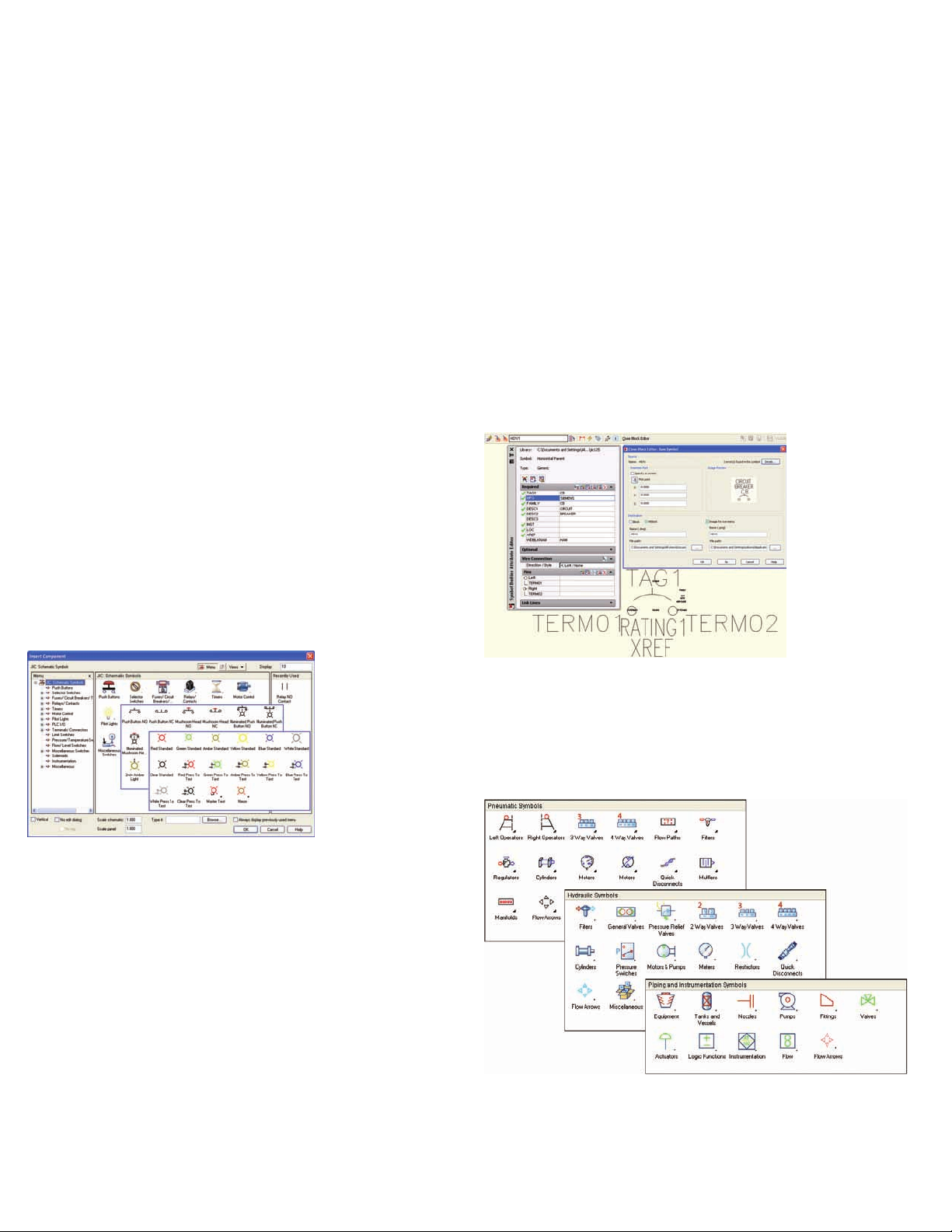
Electrical Component Libraries
Easily select commonly used devices to quickly
create electrical control systems designs. AutoCAD
Electrical provides a simple menu-driven system
for inserting electrical devices. Each menu provides
access to a comprehensive symbol library that includes push buttons, selector switches, pilot lights,
relays, contacts, fuses, terminals, and more.
Symbol Builder
Guide and manage the creation and conversion of
AutoCAD
cal symbols. Built on top of the AutoCAD Block
Editor, the Symbol Builder helps create electrical
symbols and black boxes that conform to the AutoCAD Electrical architecture.
Multidiscipline Symbol Libraries
Quickly generate accurate pneumatic, hydraulic,
and piping and instrumentation diagram (P&ID)
schematics. The comprehensive symbol libraries
include devices such as valves, operators, manifolds,
meters, regulators, filters, and more.
®
blocks into intelligent AutoCAD Electri-
Support for Multiple Design Standards
Meet your customers’ design requirements with
support for the JIC, IEC, JIS, and GB international
standards. Select symbol libraries, cross-reference
settings, wire and device tagging conventions, and
much more to meet geographic design requirements.
User-Defined Attributes
Add custom attributes to AutoCAD Electrical symbols and have their contents available in any project
reports. Easily communicate company-specific design
data by using newly defined metadata to extract
information for standard reports.
4
Page 5
Design and Drafting Productivity Tools
AutoCAD Electrical software oers controls designers
immediate productivity gains with a complete set of specialized
features and tools developed specifically for the creation of
accurate, industry-standard electrical control systems.
Streamlined Design Environment
AutoCAD Electrical features a streamlined user
interface. Find your favorite tools and commands
faster, locate lesser-used tools more eciently, and
discover relevant new features more easily. The result
is less time searching through menus and toolbars,
and more time getting your work done.
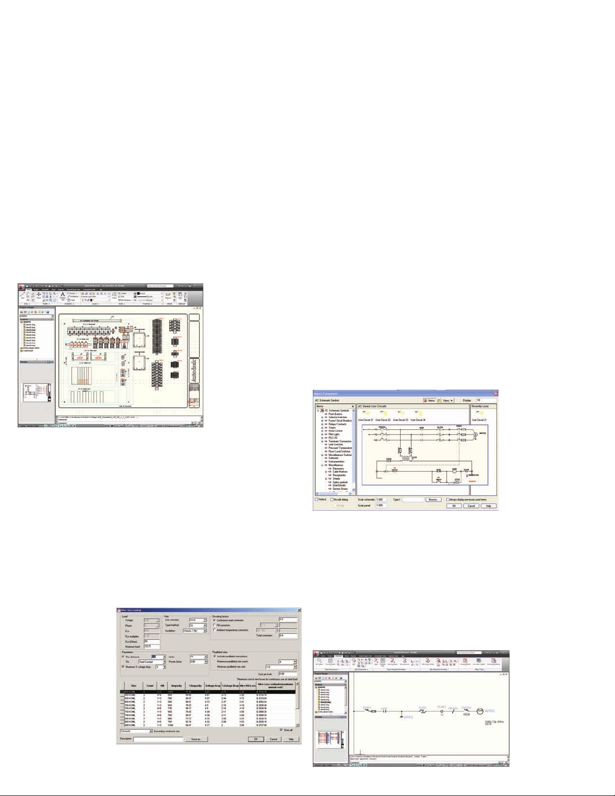
Circuit Builder
Reduce design time and increase drafting eciency
by automating the creation of controls circuits.
Dynamically generate rules-based controls circuits
based on defining functional requirements, such as
components, wiring, ratings, and catalog data.
Make better design decisions based on de-rating factors such as wire material type, insulation temperature rating, ambient temperature, run length, power
conductor bundling and maximum allowable voltage
drop. Circuit Builder can also suggest fuse, breaker,
and disconnect ratings based upon motor or power
feed load.
Reuse Circuits
Slash design time by reusing common circuits.
AutoCAD Electrical gives users the ability to build
commonly used circuits once and then save them for
reuse in future designs. When you place a saved circuit into a new design, AutoCAD Electrical automatically renumbers the wires and devices in the circuit
to match the configuration of the current drawing or
project.
The Circuit Builder tool gives you the necessary information to help you make sound engineering decisions
that are also environmentally “green.” For example,
the conductor size that meets the minimum code
requirements may be the least expensive to purchase,
but it may not provide the best long-term energy and
cost savings.
Circuit Builder provides
dynamic display of worstcase energy loss costs
for a range of conductor
sizes against various
installation and ambient
factors. Suggested wire
conductor sizing can be
automatically calculated
based upon an electrical
code requirement.
One-Line Diagrams for Motor Control
Quickly create and edit one-line circuit representations that can then help drive accurate annotation of
three-line schematic circuit equivalents.
Building on the popular Circuit Builder tool for
three-phase motor control, AutoCAD Electrical now
enables you to interactively create one-line motor circuit and power feed representations. One-line circuit
representations can help drive three-line schematic
circuit generation and vice versa.
5
Page 6

Design and Drafting Productivity Tools
Multiple Drawing Interface Aware
Simultaneously view and edit multiple drawings at
once. AutoCAD Electrical fully supports the multiple
document interface (MDI) standard, allowing you to
have multiple drawings open at one time. Now you
can cut and paste design information between two
open drawings without having to close one of them.
Multiple Wire Insert
By enabling designers to insert multiple wires with a
single command, AutoCAD Electrical automates the
process of connecting devices with several connection points. And, faster design helps ensure that your
projects stay within budget—and on time.
New Drawing Command
With a single click of a button, you can begin a new
drawing and know that AutoCAD Electrical is fully
aware of the current project settings. After you
choose a template with the appropriate title block
and drawing border, the new drawing automatically
becomes part of the active project and you are ready
to start inserting devices.
Swap Block Utility
Save hours of rework by quickly replacing each
instance of a symbol throughout a project. Swap
instances of a block or an individual symbol wherever
it is used in a project. You can even swap symbols for
an entire project between two symbol libraries. For
example, if you need to change the standard used in a
project, just run this command to automatically swap
each JIC device out with its IEC equivalent.
Retagging Components
Reduce design time and help eliminate errors by
retagging all components in a project with a single
command. This single command enables users to
change the format of component tags during a project to accommodate customer changes on the fly.
6
Page 7

Design and Drafting Productivity Tools
Fixed Wire Numbers and Component Tags
AutoCAD Electrical enables you to easily accommodate design modifications late in the cycle
without aecting previous work. When you change
the status of wire numbers and component tags to
a “fixed” format, they remain unaected during a
project-wide renumbering of wires or retagging of
components. If changes are required after the shop
floor has the designs, you can easily add new wire
numbers and device components without aecting
the existing wire numbers.
Wire Label Export for Electrical Design
Slash the time it takes to create an accurate set of
wire labels for a project. With the Wire Label Export
command, you can rapidly extract wire numbers
from an entire project and print the required labels
for each wire.
Toggle Normally Open/Normally Closed
With a single mouse-click, switch the state of a device
from normally open to normally closed and vice versa. If that device is part of a parent/child relationship,
such as a relay coil and contact, AutoCAD Electrical
automatically updates the corresponding device.
Device Navigation
Don’t waste any more of your valuable time managing device relationships. With AutoCAD Electrical
you can easily view and navigate relationships
between devices using the Surfer command. Simply
click a component in the panel layout drawing
and quickly “surf” to the corresponding schematic
device. This command works across multiple drawings in a project and also works on devices with a
parent/child relationship, auxiliary contacts, and
item numbers.
Open and Flexible API
Create simplified custom front-end interfaces or automated workflows using an open architecture that
integrates with existing business and engineer¬ing
systems. Use the flexible and open API (applica-tion
programming interface) in AutoCAD Electrical to
extend its power and functionality to meet specific
design and drafting needs. This built-in API consists
of nearly 200 programming entry points into the
software, so users can easily integrate AutoCAD
Electrical with their existing business and engineering systems.
Drawing Navigation Features for Control
Designers
Quickly navigate through drawings within a project.
Use the previous/next buttons to each drawing in the
project without having to open individual files.
7
Page 8

Schematic Design Tools
Create and modify electrical control schematics more accurately
and in fraction of the time it takes with AutoCAD
®
.
Electrical-Specific Drafting
Commands
Save hours of design time using specialized drafting features in AutoCAD
Electrical developed specifically for
designing control systems. Quickly
trim wires, copy and delete components or circuits, and scoot and
align components for easier drawing
creation.
Ladders and Reference Line Numbers
Use the flexible ladder insertion functionality in
AutoCAD Electrical to quickly place ladders into
a drawing, minimizing the redundancy of creating control drawings. Place ladders horizontally or
vertically while maintaining complete control over
all ladder characteristics, including rung spacing,
number of rungs, and ladder width. Reduce tedious
manual processes with automatic placement of
reference line numbers based on a predefined
configuration.
Automatic Wire Gaps
Eortlessly create easy-to-read schematics. Whenever two wires cross in an electrical design, AutoCAD
Electrical automatically indicates which wire passes
through. You can choose from wire gaps, loops, or
solid wires to show crossing wires.
Visual Wiring Sequence Indicators
Eciently communicate design intent to manufacturing and avoid wiring errors by graphically indicating the proper wiring sequence of a circuit directly
on the schematic. . When you make changes to a
wire sequence, the updated information is automatically accurately reflected in the from/to wire list
report.
Revise Ladder
With AutoCAD Electrical you don’t have to start from
scratch when you need to modify a ladder in your
design. Use the Revise Ladder command to modify
ladders already inserted into drawings. Without
deleting and starting over again, you can modify
most aspects of the ladder, including rung spacing
and number of rungs, as well as starting and ending
reference numbers. This single command saves hours
of manual editing and helps ensure that your time is
spent on high-value work.
8
Page 9

Schematic Design Tools
Insert Rungs
Being able to quickly insert rungs into an existing ladder greatly speeds up the drafting of electrical control schematics. Simply click anywhere inside a ladder
to insert a new rung complete with wire connection
dots and automatically align it with the corresponding wire numbers.
Three-Phase Motor Control
Save time and increase productivity when creating
three-phase motor circuits. Quickly design motor
circuits using intelligent, built-in symbol libraries that
include three-pole breakers, switches, motor contactors, and more. When you insert them, these symbols
adapt to the underlying three-phase rung spacing
automatically.
Source and Destination Markers
Quickly track wires from page to page within a project. When a wire starts on one drawing and continues
onto another, you can connect them electronically
using the source and destination signals.
Cable and Conductor Tracking
Easily manage cable and conductor usage in AutoCAD Electrical projects with automatic tracking
capabilities. Designate individual wires as belonging
to a cable, and then generate reports based on cable
usage for fabrication purposes. Similar to inserting
components, when you assign manufacturer part
number information to cables, AutoCAD Electrical
automatically tracks and reports conductor usage
based on that part number.
Connector Generator
Quickly generate connectors by providing minimal
information, such as the number of pins and orientation. The resulting connector is ready to be wired into
a design. With AutoCAD Electrical, you’ll be able to
generate accurate point-to-point style designs in a
fraction of the time it takes with traditional AutoCAD
software.
Project Interface
Easily manage and navigate the many individual
DWG™ files that make up an electrical control systems project with the AutoCAD Electrical project
interface. The intuitive file management features
in AutoCAD Electrical let you spend more time
designing and less time organizing files.
9
Page 10

Panel Layout Tools
Quickly and easily create panel layout drawings with
intelligent updating to reduce errors.
Create Smart Panel Layout Drawings
from Electrical Schematics
Using AutoCAD
drawings gives you a systematic means of checking
that no devices are missed and makes an electronic
link between the representation of the device in the
schematic and panel drawings.
Here’s how it works: Once you have created an electrical schematic, the software extracts a list of schematic components for placement in the panel layout
drawings. You simply choose a device from the list
and drag it into place. The physical “footprint” representation of each schematic device is inserted into
the layout at the point you select. Then the software
creates an electronic link between the schematic and
panel device representations. So when you change
key data on one drawing, you get a prompt for
permission to update the other. Even non-schematic
items like wire duct and mounting hardware can be
added to the layout and automatically combined to
create a “smart” panel bill of materials (BOM) report.
®
Electrical to create panel layout
Starting Designs with a Panel Layout Drawing
AutoCAD Electrical provides a flexible design environment that works the way you want to work. You
can start designs by creating a panel layout drawing
and using it to drive the creation of the corresponding logical control schematics. This feature gives you
the boost you need for tight turnaround times and
supports the needs of individual designers.
Location Boxes and Markers
Quickly and easily associate groups of devices with
a specific panel location using the Location Box
command. Apply location markers on the schematic
that represent the corresponding panel location. This
capability makes it easy to identify locations for a
device or group of devices, resulting in more accurate
panel layouts.
Insert Balloons on Panel Devices
Save time by automatically annotating control panel
drawings with intelligent item balloons that coincide
with the panel BOM.
10
Page 11

Programmable Logic Controller (PLC) Tools
AutoCAD Electrical includes a set of tools specifically designed
to increase your productivity and accuracy when working with
PLC I/O drawings.
PLC I/O Libraries
Quickly create PLC I/O drawings by selecting from a
library of more than 3,000 intelligent PLC I/O modules from the industry’s most popular vendors.
PLC I/O Import/Export
Export critical I/O address and description information into multiple file formats. Exchange data
bi-directionally between AutoCAD Electrical and
Rockwell Automation’s PLC programming software or
Schneider Electric’s Unity™ software products. Reusing crucial design data between AutoCAD Electrical
and the corresponding PLC program helps you reduce
design time and minimize errors.
Automatically Create PLC/IO Drawings from
Spreadsheets
Generate a complete set of PLC I/O drawings
simply by defining the project’s I/O assignments in
a spreadsheet program. This capability can save you
a tremendous amount of design time by virtually
eliminating the need to create those drawings in an
AutoCAD
Once the drawings have been created, easily export
the I/O information and descriptions to a format
that most PLC programming software packages can
read. The PLC programmer won’t need to recreate
addresses and their descriptions. Then import the
descriptions on each PLC I/O point into your PLC program to maintain consistency between your drawings
and your PLC program.
PLC Module Builder
The PLC module builder makes it easy to add PLC I/O
modules to the standard library. If desired modules
are not included in the currently library, you can
simply add them through a graphical interface.
®
environment.
11
Page 12

Comprehensive Terminal Management
Increase design accuracy and reduce the complexity of
working with terminals in a design.
Graphical Terminal Strip Generator
Slash design time by automatically generating graphical terminal strip layouts based on schematic design
information for use in panel layout drawings or terminal plans. You can choose to generate these terminal
strips in a graphical or table format. AutoCAD Electrical automatically populates terminal strip layouts
with the wiring information for each side of the strip
as defined in the Terminal Strip Editor.
Terminal Jumpers
Easily view, create, and edit jumpers within the
Terminal Strip Editor.Reduce design time and help
eliminate errors by accurately representing terminal
jumpers as part of the control design.
Inserting Spare Terminals
Provide accurate bill of material (BOM) information
by eliminating the guesswork encountered when
planning for spare terminal needs. Users can insert
spare terminals through the Terminal Strip Editor and
accurately update various terminal reports.
Terminal Strip Editor
Easily manage and edit terminals throughout a project with the simplified Terminal Strip Editor interface.
With only a few clicks, you can insert spare terminals
or make modifications, such as reversing the left and
right wiring information for a terminal.
Multitier Terminals
Reduce the complexity of using multilevel terminals
in a control design. AutoCAD Electrical enables you
to define and manage the terminal numbers as well
as all connectivity information, within a single, easyto-use dialog.
Direct to Terminal Wire Sequencing
Deliver more accurate reports by taking advantage
of the flexibility in the level of control available when
defining the wire connection sequence. Land wires
from multiple devices onto a common terminal, and
have all information accurately reflected in various
terminal and wiring reports.
12
Page 13

Collaboration and Interoperability
The sharing of accurate design data between AutoCAD
Electrical and other Autodesk
®
applications enables electrical
and mechanical teams to smoothly collaborate on digital
prototypes.
Link to the Cable and Harness Functionality of
Autodesk
Quickly create accurate 2D and 3D electrical control
designs using the bi-directional interoperability
between AutoCAD
tor
information for cables and conductors from AutoCAD Electrical to Autodesk Inventor Professional to
automatically create a 3D harness design. And, pass
wire-connectivity information from Autodesk Inventor Professional to AutoCAD Electrical to automatically create the corresponding 2D schematics.
®
Inventor® Professional
®
®
Professional software. Pass electrical intent
Electrical and Autodesk® Inven-
Multiuser Environment
Collaborate more eectively and increase productivity while sharing projects within workgroups.
AutoCAD Electrical control design software provides drawing status indicators and better control
of project-wide commands to improve eciency in
multi-user environments.
Publish Designs on the Web
AutoCAD Electrical makes it easy to share designs
with your extended enterprise by publishing either
individual drawings or entire projects on the web.
AutoCAD Electrical creates the HTML pages as well
as the links you need to post your complete design
to the web.
DWF Tools
Publish DWF
turing design applications, and securely collaborate
on 2D and 3D designs with customers, suppliers, planners, and others outside your engineering workgroup.
Using free* Autodesk
members can digitally review, measure, mark-up, and
comment on your 2D and 3D designs while protecting your intellectual property. Tight integration with
Autodesk manufacturing products enables accurate
communication of design information, including
assembly instructions, bills of material (BOMs), and
finite element analysis (FEA) results without requiring
CAD expertise. Autodesk Design Review software
automatically tracks comments and their status,
and the DWF-based markups can be round-tripped,
helping speed the revision process and minimize
information loss.
™
files directly from Autodesk manufac-
®
Design Review software, team
Share Drawings and Track Changes
Easily exchange data with customers or suppliers in
native DWG™ format. AutoCAD Electrical drawings
can be viewed and edited by any DWG-compatible
program such as AutoCAD or AutoCAD
ware. With the built-in AutoCAD Electrical revision
tracking functionality, you can track all changes
made to your drawings since the last update, no
matter how many people accessed them.
®
LT soft-
*Free products are subject to the terms and conditions of the end-user license agreement that accompanies download of the software.
13
Page 14

Data Management and Reporting Tools
Fully integrated data management tools make it easy to
securely store and manage your work-in-process electrical
design data. AutoCAD
®
Electrical also includes built-in tools
that instantly generate and update critical reports so you can
provide accurate information to manufacturing and save hours
on document maintenance.
Integrated Data Management
Accelerate development cycles and increase your
ROI by reusing existing designs. AutoCAD Electrical includes integrated data management tools
for workgroups that securely store and manage
work-in-progress electrical design data and related
documents.
Autodesk
Autodesk
separately and previously known as Autodesk
Productstream®) securely stores and manages
engineering information, design data, and
documents, enabling you to shorten the design-tomanufacturing process. It helps design, engineering,
and manufacturing departments across separate
locations collaborate and share Digital Prototyping
information. It also gives your design departments
advanced tools to track engineering change orders,
manage BOMs, and promote earlier collaboration
through integration with manufacturing business
systems. With support for multi-CAD environments,
Vault allows you to share and manage designs and
engineering data created with third-party software
and AutoCAD
lifecycle.
®
Vault Manufacturing
®
Vault Manufacturing software (sold
®
software throughout the product
®
Automatic Report Generation
Drastically reduce the time required to create and
update reports, while removing associated errors
of producing reports manually. Report generation
in AutoCAD Electrical is simple, customizable, and
gives you the option of running multiple reports
with a single command.
You can automatically generate reports that cover
bills of material (BOM), from/to wire lists, PLC I/O,
terminal plans, cable summaries, and cross-referencing reports.
Customize reports to display relevant information
by sorting and filtering available fields, which can
be run on a current drawing, collection of drawings, the entire project, or a specific location or
panel. Place reports into a drawing as a smart table
object that can be easily updated later or saved to a
file. AutoCAD Electrical supports saving reports in
ASCII, Microsoft
or XML formats.
®
Excel®, Microsoft® Access™, CSV,
Surfable Reports
Navigate reports and their corresponding designs
with the surfable reports feature. When you place
reports into a design as a table, you can click the
various fields to instantly find the corresponding
devices in the schematics or panel layout drawings.
Drawing List Report
AutoCAD Electrical can extract a list of project
drawings that lists drawing numbers, titles, dates,
revisions, and other important data. Create a list of
data extracted from the project drawing title blocks
14
and save to file, print, or insert it into a drawing.
Page 15

Data Migration Tools
Save hours of rework by leveraging your existing design data
from AutoCAD
®
and other products. Automatically convert
data into intelligent AutoCAD® Electrical designs without
losing previous customizations.
Migration Utility
The migration utility lets you easily migrate from
your previous version of AutoCAD Electrical design
software to the latest release while preserving your
existing data and settings.
AutoCAD Data Migration
Quickly bring existing designs created in AutoCAD
or AutoCAD LT
for further modification with the data migration
utilities. The migration tools in AutoCAD Electrical, drastically speed up the conversion of native
AutoCAD data into intelligent AutoCAD Electrical
designs. You’ll be able to realize the advantages of
using purpose-built electrical design tools faster.
®
software into AutoCAD Electrical
promis•e Data Migration
Users of promis•e
rework by easily migrating designs into AutoCAD
Electrical design software using the promis•e data
migration tools.
Content Database Merge Utility
Use this powerful utility to easily merge existing
manufacturer catalog databases, PLC I/O libraries,
footprint lookup databases, and corresponding footprint symbols with content delivered in each new
release. You’ll be able take full advantage of content
additions in new releases, without losing previous
customizations you made to current content libraries.
®
®
software can avoid hours of
15
Page 16

Digital Prototyping for the Manufacturing Market
Autodesk, a world-leading supplier of engineering software,
provides tools that let viewers experience ideas before they
are real. By putting powerful Digital Prototyping technology
within the reach of mainstream manufacturers, Autodesk is
changing the way manufacturers think about the design process
and helping create more productive workflows. The Autodesk
approach to Digital Prototyping is scalable, attainable, and costeective; allows a broader group of manufacturers to realize
its benefits with minimal disruption to existing workflows;
and provides the most straightforward path to creating
and maintaining a single digital model in a multidisciplinary
engineering environment.
Learn More or Purchase
Access specialists worldwide who can provide product expertise, a deep
understanding of your industry, and value that extends beyond your software
purchase. To purchase AutoCAD Electrical software, contact an Autodesk
Premier Solutions Provider or Autodesk Authorized Reseller. Locate a reseller
near you at www.autodesk.com/reseller.
Autodesk Learning and Education
From instructor-led or self-paced classes to online training or education
resources, Autodesk oers learning solutions to fit your needs. Get expert
guidance at an Autodesk Authorized Training Center (ATC
tools online or at your local bookstore, and validate your experience with
Autodesk certifications. Learn more at www.autodesk.com/learning.
Autodesk Services and Support
Accelerate return on investment and optimize productivity with innovative
purchase methods, companion products, consulting services, and support from
Autodesk and Autodesk authorized partners. Designed to get you up to speed
and keep you ahead of the competition, these tools help you make the most
of your software purchase—no matter what industry you are in. Learn more at
www.autodesk.com/servicesandsupport.
Autodesk Subscription
Get the benefits of increased productivity, predictable budgeting, and simplified
license management with Autodesk
of your Autodesk software and any incremental product enhancements, if
these are released during your Subscription term. In addition, you get exclusive
license terms available only to Subscription members. A range of community
resources, including web support direct from Autodesk technical experts,
self-paced training, and e-Learning, help extend your skills and make Autodesk
Subscription the best way to optimize your investment. Learn more at
www.autodesk.com/subscription.
®
Subscription. You get any new upgrades
®
) site, access learning
*Free prod ucts are subject to t he terms and conditions of the end-user license agreement that accompan ies
download of this software.
Autodesk , AutoCAD, AutoC AD LT, Autodesk Inventor, AutoL ISP, DWF, DWG , DWG (logo), Inventor,
Produc tstream, and Visual L ISP are registered tra demarks or tradem arks of Autodesk, I nc., and/or its
subsidiaries and/or aliates in the USA an d/or other countries. A ll other brand names , product names , or
trademarks belong to their res pective holder s. Autodesk reser ves the right to alter pro duct oerings and
specific ations at any time without n otice, and is not responsible for typograp hical or graphical err ors that may
appear in this d ocument.
© 2009 A utodesk, Inc. Al l rights reserved . 225A1-0 00000-MZ07
 Loading...