

Page 1

Preview Guide
AutoCAD®2010
www.autodesk.com/autocad
Page 2

AUTOCAD 2010 PREVIEW GUIDE
Table of Contents
Introduction ........................................................................................................................................................ 3
User Interface ..................................................................................................................................................... 3
Initial Setup ..................................................................................................................................................... 3
Workspaces .................................................................................................................................................... 4
Application Menu ............................................................................................................................................ 4
Ribbon ............................................................................................................................................................ 5
Quick Access Toolbar ..................................................................................................................................... 7
New Features Workshop ................................................................................................................................ 9
Document .......................................................................................................................................................... 10
Parametric Drawing ...................................................................................................................................... 10
Dynamic Blocks ............................................................................................................................................ 16
Annotation Tools ........................................................................................................................................... 20
Color Selection ............................................................................................................................................. 22
Measure Tools .............................................................................................................................................. 23
Reverse Tools .............................................................................................................................................. 24
Spline Editing Tools ...................................................................................................................................... 25
Purge Tools .................................................................................................................................................. 27
Viewport Rotation Tools ................................................................................................................................ 28
External References ..................................................................................................................................... 28
Sheet Sets .................................................................................................................................................... 30
Quick Views .................................................................................................................................................. 31
Communicate .................................................................................................................................................... 31
PDF Support ................................................................................................................................................. 31
Drawing File Format ..................................................................................................................................... 33
3D Printing .................................................................................................................................................... 34
eTransmit ...................................................................................................................................................... 35
Autodesk Seek ............................................................................................................................................. 35
Explore .............................................................................................................................................................. 37
Conceptual Design ....................................................................................................................................... 37
Free-Form Design ......................................................................................................................................... 40
Customize ......................................................................................................................................................... 44
CUIx File ....................................................................................................................................................... 44
Action Macros ............................................................................................................................................... 44
Online License Transfer ................................................................................................................................ 46
Summary ........................................................................................................................................................... 47
www.autodesk.com/autocad http://heidihewett.blogs.com/ 2
Page 3

AUTOCAD 2010 PREVIEW GUIDE
Introduction
With AutoCAD® 2010 software, you can tackle your most challenging problems with ease. Your designs can
now exist in any shape imaginable, thanks to free-form design tools. Many critical features have been
automated, making your workflow more efficient and the move to 3D design even smoother. Sharing and
working on projects with colleagues has never been easier, thanks to multiple upgrades to our PDF capabilities
and the incredible addition of 3D printing. With these and countless other new capabilities you’ve bee n asking
for, AutoCAD 2010 takes any idea and turns it into a reality faster than ever before.
User Interface
Initial Setup
Easily tailor the AutoCAD environment to meet your needs using Initial Setup, which is displayed the first time
you launch AutoCAD. With Initial Setup you can choose your industry as well as workspace and drawing
template preferences. The choices you make in the Initial Setup affect the default settings of various AutoCAD
functionality, including drawing templates, Autodesk
Unified Online Experience portal, and workspaces.
®
Seek filters, Autodesk Developer Network partners, the
Figure 1. Initial Setup
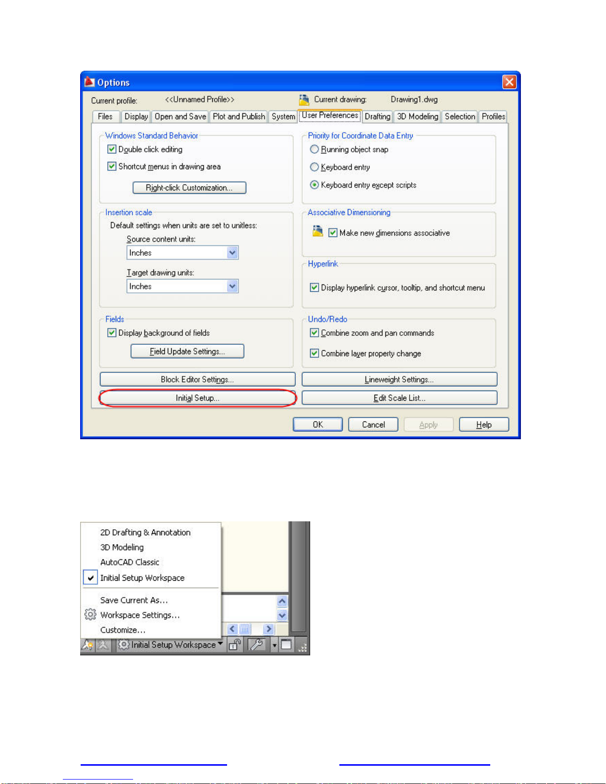
You can access Initial Setup from the User Preferences tab of the Options dialog box.
www.autodesk.com/autocad http://heidihewett.blogs.com/ 3
Page 4
AUTOCAD 2010 PREVIEW GUIDE
Figure 2. Initial Setup on User Preferences tab of the Options dialog box
Workspaces
When you specify Initial Setup options, AutoCAD automatically creates a new workspace based on your
choices and sets it current. The name of the current workspace is displayed in the status bar next to the
Workspace Switching icon and you can select it to access the Workspace menu.
Figure 3. Workspace menu
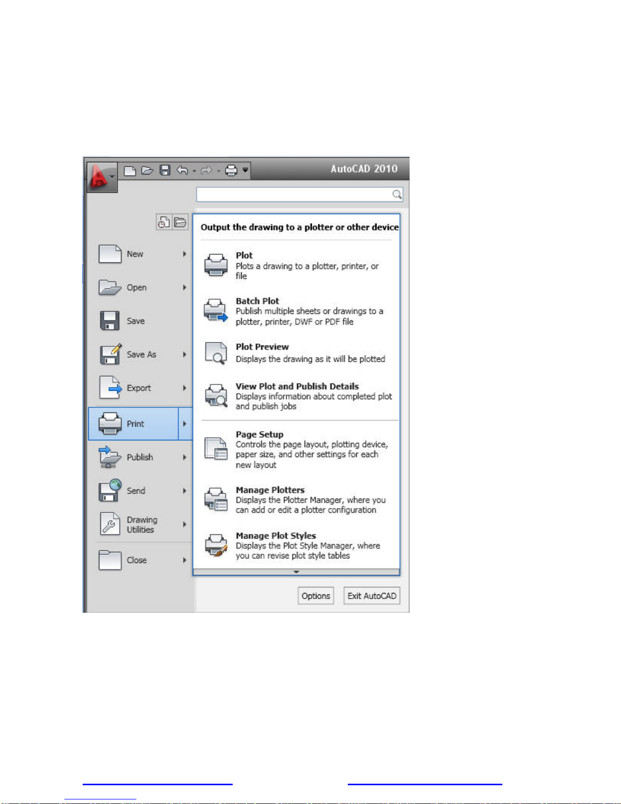
Application Menu
The Application menu, in the upper left corner of the AutoCAD display, has been streamlined to provide easy
access to common tools. You can create, open, save, print, and publish AutoCAD files, send the current
www.autodesk.com/autocad http://heidihewett.blogs.com/ 4
Page 5
AUTOCAD 2010 PREVIEW GUIDE
drawing as an email attachment, and produce electronic transmittal sets. In addition, you can perform drawing
maintenance, such as audit and purge, and close drawings.
A search tool at the top of the Application menu enables you to query the Quick Access toolbar, Application
menu, and the currently loaded ribbon to locate commands, ribbon panel names, and other ribbon controls.
Buttons at the top of the Application menu provide easy access to Recent or Open documents and a new option
in the Recent Documents list enables you to sort by access date in addition to size, type, and ordered list.
Figure 4. Application menu
Ribbon
The ribbon has been updated to provide greater flexibility, easier access to tools, and consistency across
Autodesk applications.
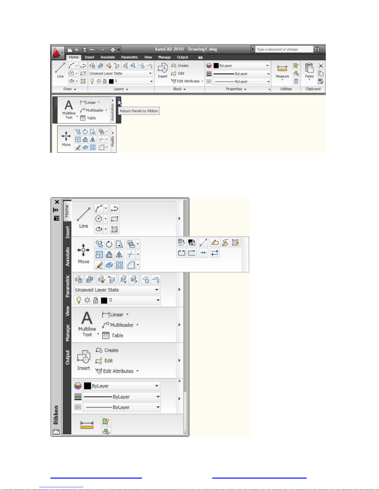
You can drag a ribbon panel off the ribbon to display it as a sticky panel. Sticky panels remain displayed, even
when selecting a different tab, until you select the option to Return Panels to Ribbon.
www.autodesk.com/autocad http://heidihewett.blogs.com/ 5
Page 6
AUTOCAD 2010 PREVIEW GUIDE
Figure 5. Ribbon and sticky panels
The vertical ribbon, which can be displayed by undocking the ribb on from its horizontal position, has been
updated to show the tab names along the side. The panel titles are displayed by default and those with
additional tools include slide-out panels. When resizing the vertical ribbon, buttons automatically flow to the next
or previous row and other elements, such as slider bars, automatically shorten or lengthen.
Figure 6. Vertical ribbon with slide-out panel
www.autodesk.com/autocad http://heidihewett.blogs.com/ 6
Page 7
AUTOCAD 2010 PREVIEW GUIDE
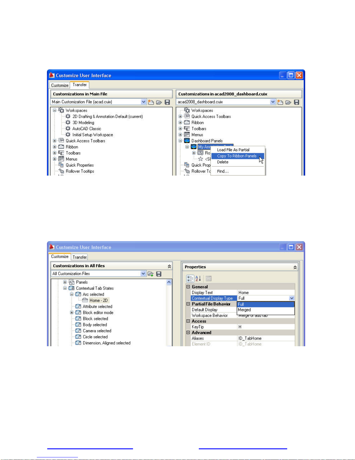
If you customized the Dashboard in AutoCAD 2008, you can easily convert your custom dashboard panels to
new ribbon panels using the Transfer tab in the Customize User Interface (CUI) Editor. The newly converted
panels are then displayed under the Ribbon Panels node in the same CUIx file as the d ashboard panels. Once
converted, you can add the new panels to a tab or transfer them to another CUIx file.
Figure 7. Dashboard conversion
Enhanced ribbon functionality in AutoCAD 2010 enables you to customize contextual ribbon tab states which
control the display of ribbon tabs and panels based on either the type of object selected in the drawing windo w
or the active command. You can display a ribbon tab that is assigned to a ribbon contextual tab state either on
its own tab or with its panels merged onto each of the ribbon tabs in the current workspace. To add a ribbon
tab, drag it from the Tabs node in the Customizations In pane to the contextual tab state. For example, if you
want the Home tab to become active whenever you select an Arc object, drag the Home-2D ribbon tab to the
Arc selected node under the Contextual Tab States. Select it and modify its display type to indicate if it should
be displayed as its own tab or merged onto each ribbon tab.
Figure 8. Ribbon Contextual Tab States
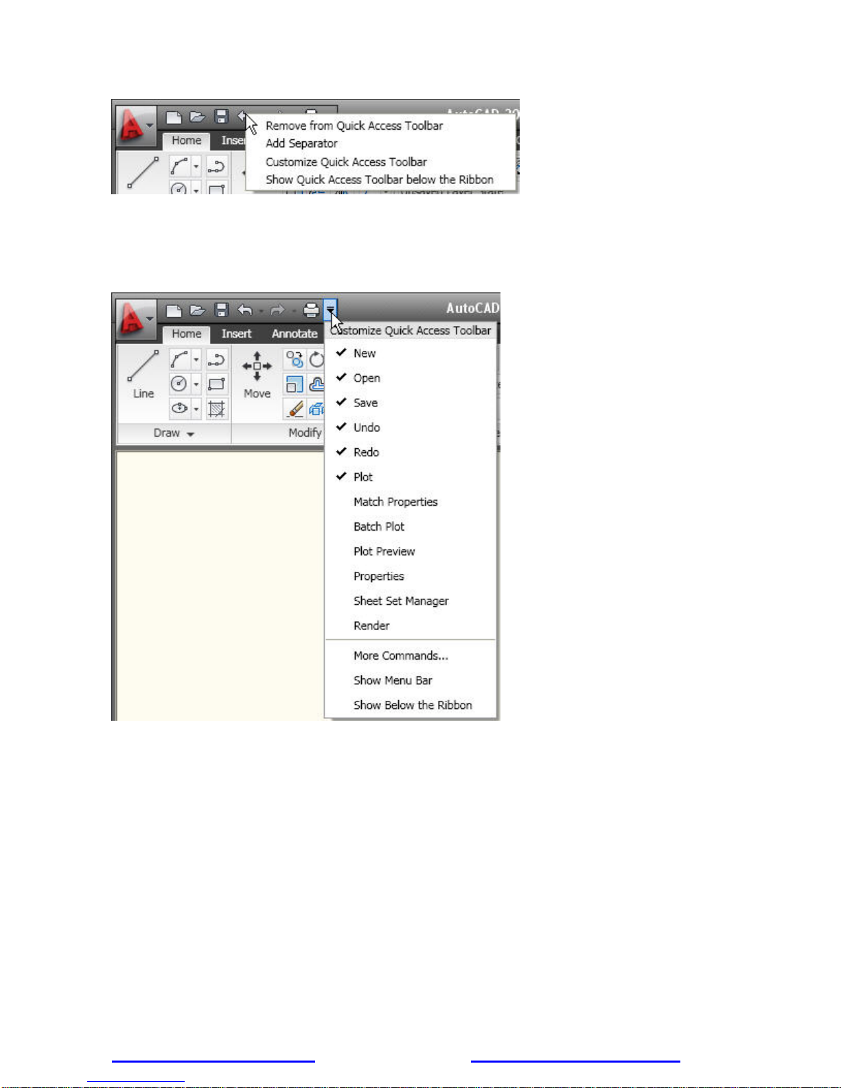
Quick Access Toolbar
The Quick Access toolbar has been enhanced with more functionality and to ensure consistency with other
Windows
options that enable you to easily remove tools from the toolbar, add separators between tools, and display the
Quick Access toolbar above or below the ribbon.
www.autodesk.com/autocad http://heidihewett.blogs.com/ 7
®
applications. The Undo and Redo tools include history support and the rig ht-click menu includes new
Page 8
AUTOCAD 2010 PREVIEW GUIDE
Figure 9. Quick Access toolbar right-click menu
In addition to the right-click menu, the Quick Access toolbar includes a new flyout menu, which displays a list of
common tools that you can select to include in the Quick Access toolbar. The flyout menu provides easy access
to additional tools using the Command List pane in the CUI Editor. Other options enable you to show the menu
bar or display the Quick Access toolbar below the ribbon.
Figure 10. Quick Access toolbar flyout menu
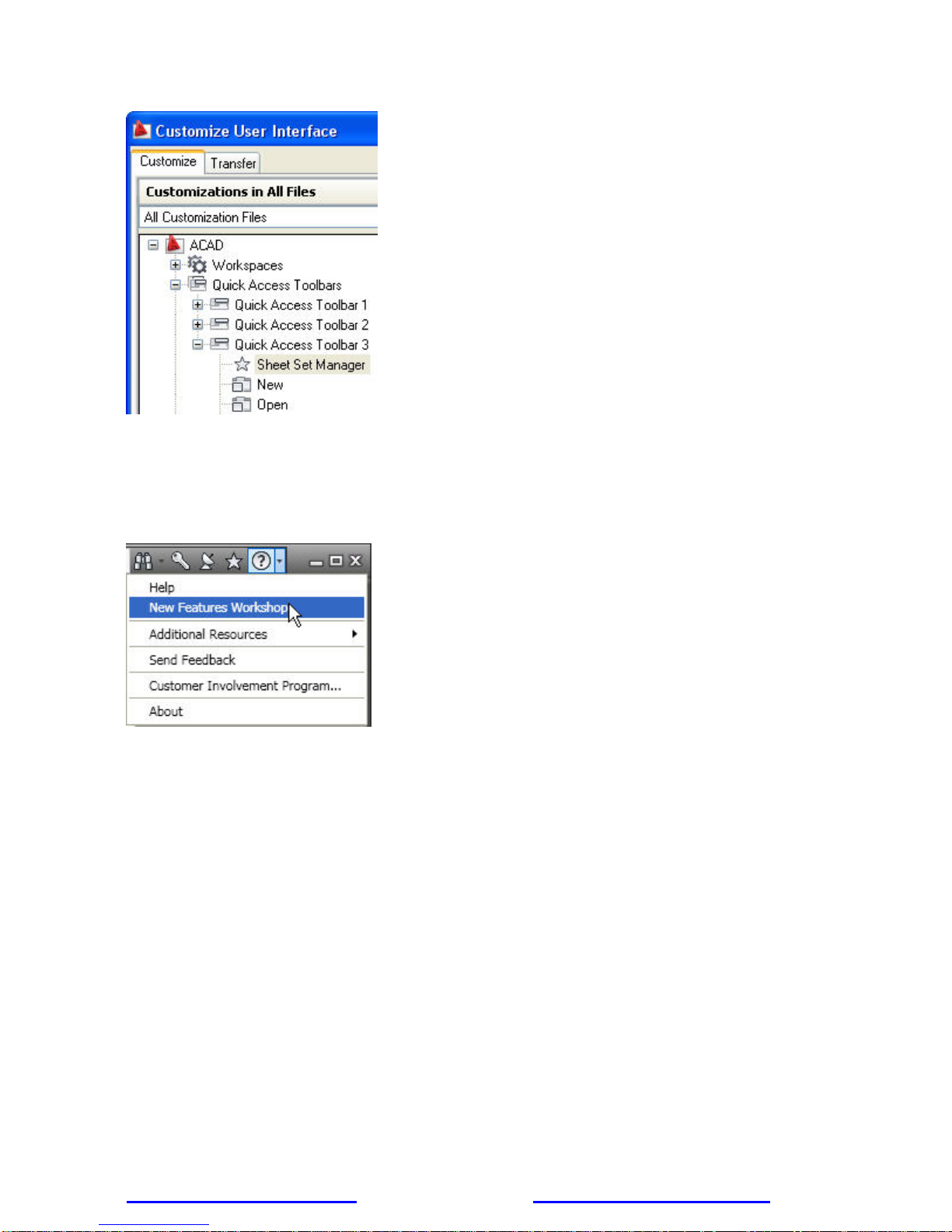
You can further customize the Quick Access toolbar using the new Quick Access toolbars node in the CUI
Editor. Create multiple versions of the Quick Access toolbar and then add them to the appropriate workspaces.
www.autodesk.com/autocad http://heidihewett.blogs.com/ 8
Page 9
AUTOCAD 2010 PREVIEW GUIDE
Figure 11. Quick Access toolbar customization
New Features Workshop
The New Features Workshop has been updated to include AutoCAD 2010 functionality. This interactive
learning tool helps you discover the newest functionality with minimal effort. You can access the New Features
Workshop from the drop-down menu on the InfoCenter toolbar, to the right of the Help button.
Figure 12. Access to the New Features Workshop
www.autodesk.com/autocad http://heidihewett.blogs.com/ 9
Page 10
AUTOCAD 2010 PREVIEW GUIDE
Document
AutoCAD is synonymous with documentation for good reason. Drive your projects from conce pt to completion
with the powerful documentation tools in AutoCAD 2010. Work faster with automation, management, and
editing tools that minimize repetitive tasks and speed your time to completion. No matter your project’s size or
scope, you can meet the challenge with AutoCAD—continuously leading and innovating documentation for over
25 years.
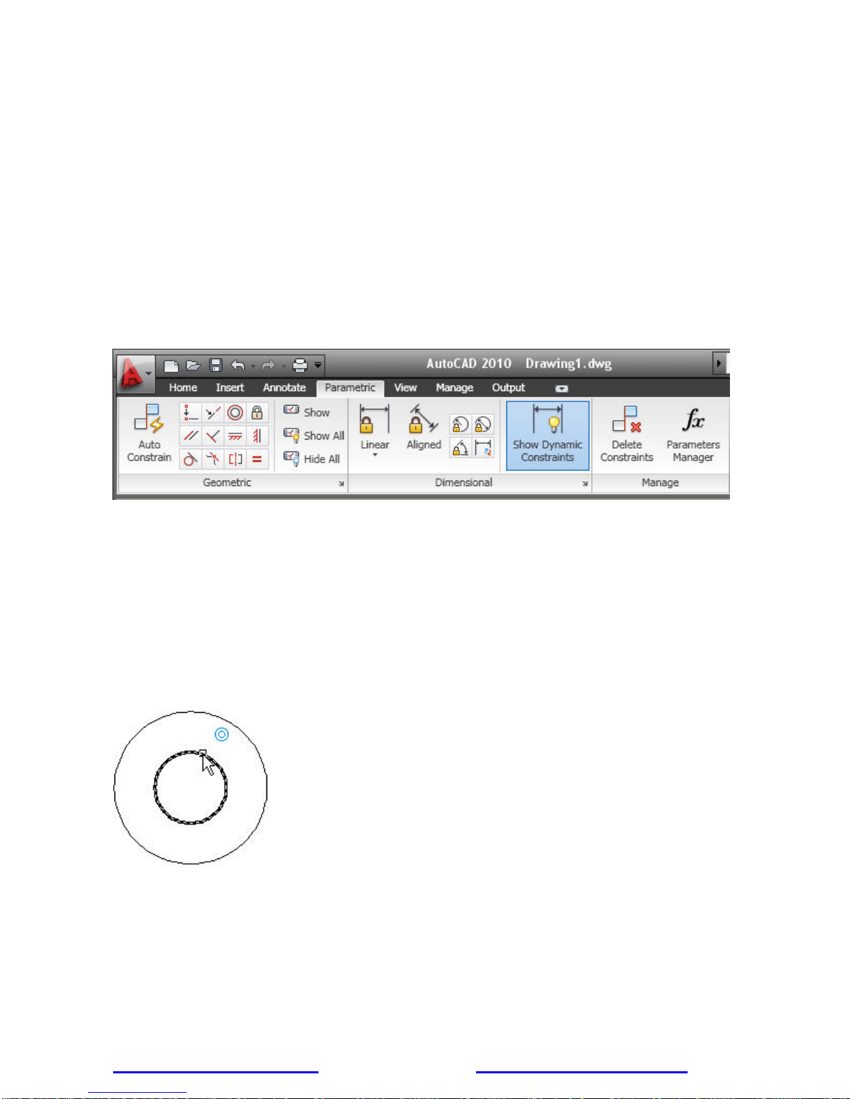
Parametric Drawing
Powerful new parametric drawing functionality in AutoCAD 2010 enables you to dramatically increase
productivity by constraining drawing objects based on design intent. Geometric and dimensional constra ints
help ensure that specific relationships and measurements remain persistent even as obje cts are modified. The
tools for creating and managing geometric and dimensional constraints are available on the Parametric ribbon
tab, which is automatically displayed in the 2D Drafting and Annotation workspace.
Figure 13. Parametric ribbon tab
Establishing Geometric Relationships
Geometric constraints establish and maintain geometric relationships between objects, key points on objects, or
between an object and the coordinate system. Pairs of key points on or between objects can also be
constrained to be vertical or horizontal relative to the current coordinate system. For example, you could specify
that two circles must always be concentric, that two lines are always parallel, or that one side of a rectangle is
always horizontal.
Applying Geometric Constraints
Geometric relationships are defined with geometric constraints, located on the Geometric Panel of the
Parametric tab of the ribbon, or with the GEOMCONSTRAINT command. When applying constraints, an icon
appears next to the cursor to help you remember which constraint you selected.
Figure 14. Concentric geometric constraint icon
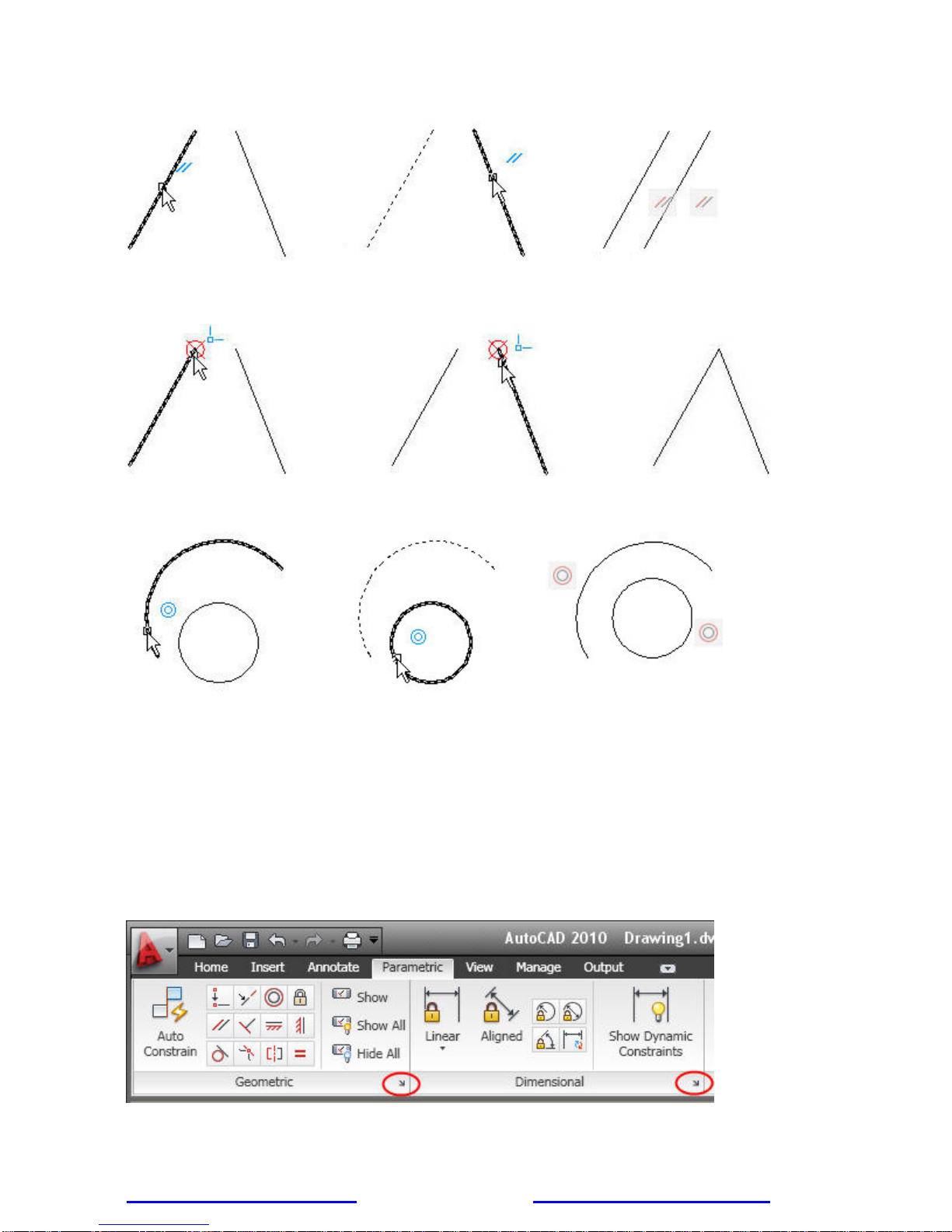
When applying a constraint to points, a temporary marker identifies the closest valid point when rolling over an
object. It generally corresponds with points that can be used as object snaps.
Whether selecting objects or points on objects to constrain, the order and pick location affects how the objects
update: the second object selected updates to satisfy the constraint. After the constraint is applied, though,
either object will update when the other is modified.
www.autodesk.com/autocad http://heidihewett.blogs.com/ 10
Page 11
AUTOCAD 2010 PREVIEW GUIDE
Figure 15. Applying a parallel constraint
Figure 16. Applying a coincident constraint
Figure 17. Applying a concentric constraint
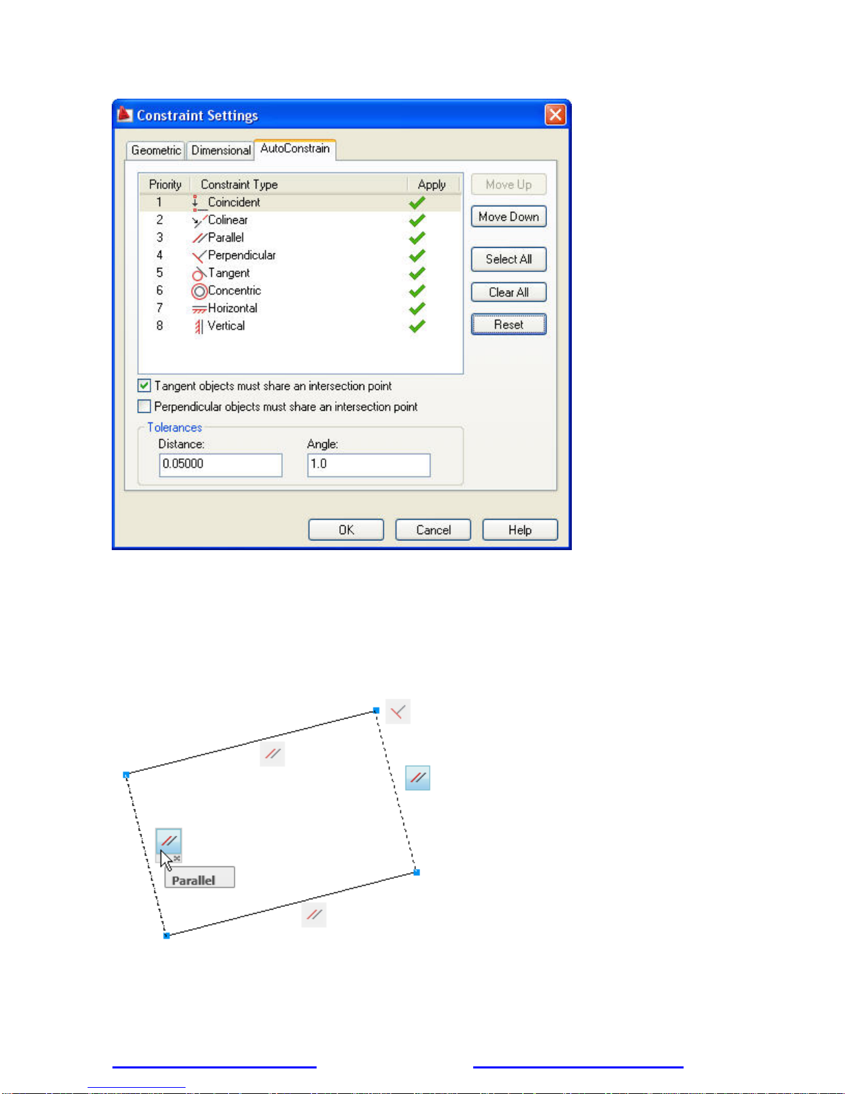
AutoConstrain
You can significantly automate the process of applying constraints using the AutoConstrain functionality,
available on the Geometric panel of the Parametric tab. AutoConstrain automatically applies constraints to
geometry that falls within specified tolerances. For example, applying AutoConstrain to a rectangle consisting of
four lines generates the appropriate coincident, horizontal, parallel, and perpendicular constraints to maintain
the rectangular shape through various edits. You can control which constraints are availab le, in what order they
are applied, and a tolerance to determine whether constraints are automatically applied. These controls are
available on the AutoConstrain tab of the Constraint Settings dialog box, which you can access from the
Parametric tab or using the CONSTRAINTSETTINGS command.
Figure 18. Access to Constraint Settings dialog box
www.autodesk.com/autocad http://heidihewett.blogs.com/ 11
Page 12
AUTOCAD 2010 PREVIEW GUIDE
Figure 19. Constraint Settings dialog box, AutoConstrain tab
Constraint Bars
Constraint bars show the constraints applied to an object. You can control the display of constrai nt bars using
the CONSTRAINTBAR command or the Show, Show All, and Hide All options on the Geometric panel of the
Parametric ribbon tab.
When constraint bars are displayed, you can pass the cursor over a constraint to view the constraint name and
the objects that it affects.
Figure 20. Constraint bar
You can further control the display of constraint bars on the Geometric tab of the Constraint Settings dialog box.
Options include the ability to individually specify which types of constraints can be displayed in the constraint
www.autodesk.com/autocad http://heidihewett.blogs.com/ 12
Page 13

AUTOCAD 2010 PREVIEW GUIDE
bar, apply transparency, and automatically show the constraint bars after applying constraints to selected
objects regardless of the current constraint bar visibility setting.
Figure 21. Constraint Settings dialog box, Geometric tab
Establishing Dimensional Relationships
Dimensional relationships put limits on measurements of geometry. For example, you could use a dimensional
constraint to specify the radius of an arc, the length of a line, or that two parallel lines are always 15 mm apart.
Changing the value of a dimensional constraint forces a change in geometry.
You can create dimensional constraints from the Dimensional panel of the Parametric tab or with the
DIMCONSTRAINT command. There are seven types of dimensional constraints, similar to the different ki nds of
dimensions: Linear, Aligned, Horizontal, Vertical, Angular, Radial, and Diameter. In fact, you can use the
DIMCONSTRAINT command to convert a traditional dimension to the corresponding dimensio nal constraint.
Dimensional constraints are assigned a name when created. The text of a dimensional constraint can display its
name, value, or its name and expression (name = formula or equation or value). A “lock” icon appears next to
all dimensional constraints to help you visually distinguish them from regul ar dime nsions. By default,
dimensional constraints are displayed with a fixed system style that is zoom-invariant—it stays the same size
relative to the screen when you zoom in and out so it is always readable.
www.autodesk.com/autocad http://heidihewett.blogs.com/ 13
Page 14

AUTOCAD 2010 PREVIEW GUIDE
Figure 22. Dimensional constraints
You can control the display of dimensional constraints, including the visibility of the lock icon, from the
Dimensional tab of the Constraint Settings dialog box.
Figure 23. Constraint Settings dialog box, Dimensional tab
Easily edit a dimensional constraint using grips or by double-clicking on the dimension text to enter values.
When you double-click, the constraint name and expression are automatically displayed regardless of the
constraint format setting. You can enter just a value, or a name and value using the format name=value (for
example, Width=1.5 or Width=Length/3). You can rename dimensional constraints, and use those names in
www.autodesk.com/autocad http://heidihewett.blogs.com/ 14
Page 15
AUTOCAD 2010 PREVIEW GUIDE
formulas to set the values of other constraints. For example, if you have a rectangle with constraints named
“length” and “width,” you could define the value of “width” as “length/3” to constrain the rectangle’s width to 1/3
of its length.
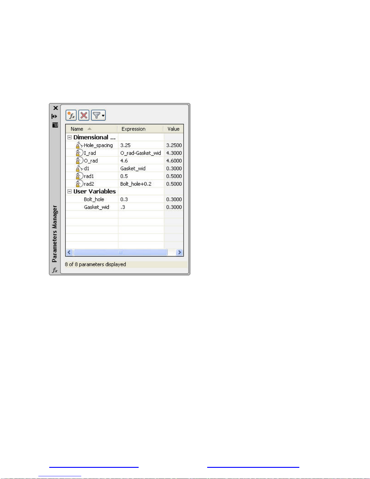
User-Defined Parameters
The Parameters Manager, available from the ribbon, enables you to manage dimensio nal parameters as well
as create and manage user-defined parameters. You can provide a mea n ingful name for the parameter and
then assign a numeric value or formula as its expression. A parameter’s expression can reference other
parameters so that its value automatically updates when the other parameter values change.
Figure 24. Parameters Manager
Constraint Forms
Dimensional constraints can take one of two forms: Annotational or Dynamic. Both forms control geom etry in
the same way, but they differ in their appearance and they way they are managed.
Dynamic dimensional constraints are not intended to be used as plotted annotation and they have a predefined
style that cannot be modified. The display height is controlled by the BPARAMETERSIZE system variable. The
visibility of dynamic constraints can be controlled in a variety of ways. First, you can show or hide all dynamic
constraints with two icons on the ribbon. Second, even if dynamic constraints are hidden, you can choose to
display them when a constrained object is selected, by using the checkbox in the Constraint Settings dialog or
the DYNCONSTRAINTMODE system variable. Finally, even if dynamic constraints are set to “Show All,” they
will only appear if at least one of the constrained objects is visible (on a layer which is On and Thawed).
Annotational constraints look just like dimension objects, and are managed the same way. They have all the
same properties as regular dimensions, including Style. Annotational constraints are intended to be used for
plotted dimensional constraints.
www.autodesk.com/autocad http://heidihewett.blogs.com/ 15
Page 16

AUTOCAD 2010 PREVIEW GUIDE
Figure 25: Rectangle with one annotational and one dynamic dimensional constraint
You can specify which constraint form is applied by default using the CCONSTRAINTFORM system variable.
Additionally, you can specify the constraint form when using the DIMCONSTRAINT command to create a new
dimensional constraint. Even after you have created a dimensional constraint, you can easily change its
constraint form using the Properties palette.
Dynamic Blocks
Dynamic blocks have been enhanced to support geometric and dimensional constraints. They also support the
ability to define a table of variations of the dynamic block, and some general enhancements have been made to
the block editing environment.
Figure 26. Block Editor ribbon tab
Geometric Constraints
You can apply geometric constraints to objects in the Block Editor in the same way as in the Drawing Edit or.
Constrained geometry in the Drawing Editor that is copied into the Block Editor, or selected when creating a
block with the Block command, will remain constrained in the Block Editor.
Constraint Parameters
You can apply dimensional-type constraints, called constraint parameters, to objects within a block. Constraint
parameters behave like dimensional constraints but they also expose their name as a pro perty for the block
reference similar to dynamic block parameters. You can access constraint parameters from the Dimensional
panel of the Block Editor tab in the ribbon or with the BCPARAMETER command. Constraint parameter options
include Linear, Aligned, Horizontal, Vertical, Angular, Radial, and Diameter.
Construction Geometry
Sometimes it is helpful to add construction geometry when constraining geometry to achieve the behavior you
desire. The Block Editor provides a construction geometry tool (BCONSTRUCTION command) that enables
you to convert existing objects to construction geometry. The construction geometry is visible in the Block Editor
and can be constrained, but it does not display or plot in the block reference.
Parameters Manager
A Parameters Manager is available in the Block Editor. It lists user parameters, legacy action parameters, block
constraint parameters, and attributes. Using the Parameters Manager, you can control whether or not a
parameter is displayed in the Properties palette for a selected block reference and you can specif y the order in
which the parameters appear.
www.autodesk.com/autocad http://heidihewett.blogs.com/ 16
Page 17

AUTOCAD 2010 PREVIEW GUIDE
Figure 27. Block Editor Parameters Manager
Test Blocks
A new Test Block tool (BTESTBLOCK command) enables you to test a block definition while authoring dynamic
blocks. When you use this tool, AutoCAD opens a temporary window, similar to a drawing window, with the
block reference already inserted. The Test Block Window is easily identifiable by the title bar, background color,
and the contextual ribbon tab which includes a button to Close Test Block. When you close the test block,
you’re automatically returned to the Block Editor.
Block Properties Table
A new Block Table tool has been added to the Block Editor. Accessible from the Dimensional panel of the
ribbon, or the BTABLE command, it displays the Block Properties Table where you can define different
variations of a property set for the block reference. You can enter properties manually or copy and paste from a
Microsoft® Office Excel® spreadsheet.
www.autodesk.com/autocad http://heidihewett.blogs.com/ 17
Page 18

AUTOCAD 2010 PREVIEW GUIDE
Figure 28. Block Properties Table
A menu grip on the inserted block reference enables you to switch between different sets of values or rows in
the table.
Figure 29. Block Properties Table grip
Selecting “Properties table..” from the grip menu displays the Block table, enabling you set the block to the
values defined by any row in the table.
Action Bars
The display and positioning of Action objects in the Block Editor is enhanced to be consistent with Constraint
bars. Action objects are no longer placed individually in the Block Editor; rather they are automatically grouped
www.autodesk.com/autocad http://heidihewett.blogs.com/ 18
Page 19

AUTOCAD 2010 PREVIEW GUIDE
into Action bars based on the parameters with which they are associated. You can toggle between the new and
old display styles by setting the BACTIONBARMODE system variable prior to entering the Block Editor.
Figure 30. Action bars
When viewing the block definition with Action bars turned on, you can quickly tell which actions are associated
with which parameters and how many actions each of the parameters affects. You can also see which
parameter has its “Chain actions” property enabled. If you roll over an action in an Action bar, both the
associated parameter and affected geometry are highlighted.
Block Editor Settings
A new dialog box, launched with the command BESETTINGS, enables you to control all the settings for the
Block Editor environment in one place. You can apply colors to objects based on their constraint status, makin g
it easy to identify objects that are partially, fully, or over-constrained, or that have no constraints at all. The
system variable BCONSTATUSMODE controls whether this shading is used.
www.autodesk.com/autocad http://heidihewett.blogs.com/ 19
Page 20

AUTOCAD 2010 PREVIEW GUIDE
Figure 31. Block Editor Settings
Authoring Blocks with Constraints versus Parameters and Actions
When creating dynamic blocks using geometric and dimensiona l constraints, it is generally recommended that
you don’t mix them with parameters and actions. For example, if you apply geometric constraints to the
geometry in the block definition, you should use constraint parameters to define custom properties for the block
instead of the action parameters. It is also recommended you add a Fix constraint to the definition and fully
constrain the block. You can check whether the block is fully constrained by clicking on the Constraint Status in
the ribbon.
Annotation Tools
Find and Replace
Find and Replace functionality has been enhanced for increased efficiency. You can use the new Zoom button
to zoom to a highlighted text object, similar to double-clicking on the item within the results list. Additional
buttons enable you to quickly create a selection set that includes all of the objects in the results list or only
those that are highlighted.
Multileaders
Edit the properties of individual Multileader segments by using the CTRL key to select the segment and then
accessing the Properties window. New grips at each corner of the leader text enable you to resize the text box
in the same way you resize a simple mtext object.
Mleader styles have been enhanced to provide you with more control over the leader connections. On the
Leader Structure tab, you can specify Vertical attachment in addition to the traditional Horizontal attachment.
On the Content tab, when a Block multileader type is selected, you can specify a scale. The block scale is also
displayed as a Multileader property in the Properties window. A new button on the Co ntent tab provides direct
access to the Text Style dialog box enabling you to create and modify text styles without exiting the Multileader
Style dialog box.
www.autodesk.com/autocad http://heidihewett.blogs.com/ 20
Page 21

AUTOCAD 2010 PREVIEW GUIDE
The MLEADEREDIT command has been streamlined by eliminating the need for you to select an optio n to add
or remove leader lines. It adds leaders by default until you select the option to remove leaders.
Mtext
Mtext improvements include a default column mode of Dynamic with manual height. In addition, the corner grips
on mtext objects are now consistent with the corner grips on table objects.
Spell Checker
The Check Spelling dialog box has been updated to include an Undo b utton, which enables you to undo actions
you made for the previous spelling mistake. In addition, the Select Objects button has been enhanced so that
you can begin selecting objects to check without first having to choose the Select Objects option from the dropdown list.
Dimensions
Enhancements to dimension styles and properties provide more control over the display and placement of
dimension text.
The Text tab of the Dimension Style dialog box has been updated with a new text placement option that
enables you to position dimension text below the dimension line. You can control the direction of the text using
the new View Direction option in which you can specify that the text be displayed from Left-to-Right or Right-toLeft. The Properties palette has been updated to include these new properties as well.
The Primary and Alternate Units tabs of the Dimension Style dialog box include new sub-unit controls for
suppression of leading zeros. You can specify a sub-units factor and suffix. For example, if the unit is 1 meter,
you could specify a sub-unit factor of 100 and sub-unit suffix of cm. In this case, when the dimension value is
less than 1, such as .96, it displays as 96 cm instead of .96 m. The new sub-units properties are also included
in the Properties palette.
Figure 32. Sub-unit controls
www.autodesk.com/autocad http://heidihewett.blogs.com/ 21
Page 22

AUTOCAD 2010 PREVIEW GUIDE
Hatch
When a hatch boundary area is not found, AutoCAD attempts to show you where the problem may have
occurred. Red circles appear around endpoints near where any gap in geometry is estimated to be.
Figure 33. Hatch boundary gap
Additional enhancements provide more robust boundary detection and the ability to edit nonassociative hatch objects. You can select on a non-associative hatch and then use intuitive grips to
dynamically change its shape.
Figure 34. Non-associative hatch editing
Color Selection
In AutoCAD 2010, you can set layer colors and pick from the AutoCAD Color Index with ease. Access the
Select Color dialog box directly from the Layer drop-down list by selecting on the layer color swatch. If the layer
has a viewport color override, the color swatch has a white border. The new color you select applies to the
appropriate viewport color override or global color. Behavior within the Select Color dialog box has a lso been
improved. As you hover the cursor over a color swatch, the arrow cursor and a black border are displayed in
addition to the traditional white border making it easier to see which swatch you are about to select.
Figure 35. Color selection
www.autodesk.com/autocad http://heidihewett.blogs.com/ 22
Page 23

AUTOCAD 2010 PREVIEW GUIDE
Measure Tools
The new MEASUREGEOM command enables you to measure the distance, radius, angle, area, or volume of a
selected object or a sequence of points. You can access these tools from the Utilities panel of the Home ribbon
tab. The default option is Distance. However, selecting a different measure tool will set it as the default for the
remainder of the AutoCAD session or until a different tool is selected.
Figure 36. Measure tools
The Distance tool enables you to measure the distance between two points. AutoCAD visually displays the
distance, delta x, delta y, and angle in the xy plane within the Drawing Editor. If you select the Multiple option,
you can continue picking points and, with each pick, AutoCAD displays the cumulative distance. Other options
within the Distance tool are similar to the Polyline command enabling you to switch between Line and Arc
measuring modes.
You can use the Radius tool to display the radius of a selected arc or circle. The Angle tool measures the angle
of a specified arc, circle, line, or vertex.
The Area tool enables you to specify points or select objects to display the included area. You can use the Add
or Subtract options to determine cumulative areas. As you specify points or select objects, the included area
dynamically highlights so that you can see what you’ve selected! Additional options within the Area tool enable
you to switch between line and arc measuring tools so that you can easily measur e curved spaces as well as
polygonal.
Figure 37. Area highlighting
www.autodesk.com/autocad http://heidihewett.blogs.com/ 23
Page 24

AUTOCAD 2010 PREVIEW GUIDE
You can use the Volume tool to specify boundary points with visual feed back similar to the Area option, and
then specify a height to determine the volume. Additionally, you can display the vo lume of selected solids or
regions.
Figure 38. Volume highlighting
Reverse Tools
The new REVERSE command enables you to reverse the direction of lines, polylines, splines, and helixes.
Simply select the object(s) to reverse. The ability to change the direction of these objects provides you with
more control, such as the display of special linetypes.
Figure 39. Reverse results
In addition to the new REVERSE command, the PEDIT command has been updated to include a new Reverse
option. Simply select the polyline you want to edit and choose the Reverse option. The results are the same as
using the REVERSE command.
www.autodesk.com/autocad http://heidihewett.blogs.com/ 24
Page 25

AUTOCAD 2010 PREVIEW GUIDE
Figure 40. Reverse option
Spline Editing Tools
The updated SPLINEDIT command includes a new option to convert a spline to a polyline. You can launch the
SPLINEDIT command from the Modify ribbon panel. Select the spline you want to edit and choose the Convert
to Polyline option. You’ll then be prompted to specify a precision for the conversion. Enter any value between 0
and 99. The higher the value, the more accurate the polyline.
Figure 41. Convert to Polyline option
www.autodesk.com/autocad http://heidihewett.blogs.com/ 25
Page 26

AUTOCAD 2010 PREVIEW GUIDE
In addition to the new Convert to Polyline option in the SPLINEDIT command, you can use the updated PEDIT
command to select a Spline object and automatically convert it to a polyline. After selecting the spline and
confirming that “Yes” you really do want to convert it, you can specify the precision between 0 and 99.
Figure 42. Spline to polyline precision
To further control the accuracy when converting splines to polylines, you can use the new
PLINECONVERTMODE variable to specify the fit method. When PLINECONVERTMODE is set to 0, polylines
are created with linear segments. When it’s set to 1 (the default), polylines are created with arc segments.
Spline Pline Pline
Precision=2 Precision=2
Plineconvertmode=0 Plineconvertmode=1
Figure 43. Pline conversion mode
The DELOBJ variable has been updated to support the PEDIT and SPLINEDIT commands. If you’re not familiar
with the DELOBJ variable, it was introduced as a way to control whether geometry used to create 3D objects
(profiles, paths, etc) is retained or deleted. It is typically accessed via the 3D Modeling tab of the Options dialog
box. When DELOBJ is set to 0, the option to Retain Defining Geometry, the original spline is retained in addition
to the new pline, which is created. When DELOBJ is set to any other option/value, the original spline is deleted.
www.autodesk.com/autocad http://heidihewett.blogs.com/ 26
Page 27

AUTOCAD 2010 PREVIEW GUIDE
Figure 44. Options dialog box
Purge Tools
The Purge dialog box has been updated to include an option for purging zero-length geometry and empty text
objects.
Figure 45. Purge dialog box
www.autodesk.com/autocad http://heidihewett.blogs.com/ 27
Page 28

AUTOCAD 2010 PREVIEW GUIDE
How do you create zero-length geometry or empty text objects? Usually by accident! For example, you might
grip-edit a line and accidentally snap one endpoint onto the other endpo int. Or you might begin creating an
mtext, enter a space, and then cancel out of it. The mtext object still exists but you can’t see it because it is
nothing more than a space. After performing the Purge operation, AutoCAD will report how many zero- le ngth or
empty text objects it purged. The same functionality is available at the Command line using the -PURGE
command.
Viewport Rotation Tools
The new VPROTATEASSOC variable enables you to control the rotation of a view within a layout viewport.
When you rotate the viewport with VPROTATEASSOC set to 1 (the default), the view will also rotate to maintain
its orientation relevant to the viewport. When it’s set to 0, the view within the viewport will not rotate even
though the viewport itself does.
Original Viewport VPROTATEASSOC=0 VPROTATEASSOC=1
Figure 46. Viewport rotation
External References
AutoCAD 2010 provides a consolidated interface and increased flexibility for working with externally referenced
file formats, including DWG
Geographic Data
Attach externally referenced drawing files using geograph ic data. If both the host drawing and the external
reference drawing have a geographic location, a new option in the External References di alog box enables you
to locate the attached xref relative to the host drawing using Geographic Data. A similar option is available in
the Insert dialog box.
Reference Tools
The Reference panel on the Insert tab of the ribbon provides tools for you to attach and modify externall y
referenced files. Use the Attach tool to select a DWG, DWF, DGN, PDF, or Image file and specify attachment
options. Additional tools enable you to clip a selected reference, adjust its Fade, Contrast, and Brightness,
control its layer visibility, display reference frames, snap to underlay geometry, and adjust xref fading.
TM
, DWFTM, DGN, PDF, and Image files.
Figure 47. Reference ribbon panel
www.autodesk.com/autocad http://heidihewett.blogs.com/ 28
Page 29

AUTOCAD 2010 PREVIEW GUIDE
When you select a reference file in the drawing, a relevant contextual tab is automatically displa yed in the
ribbon. For example, if you select a PDF underlay, the PDF Underlay tab is displayed providing you easy
access to PDF underlay tools.
Figure 48. PDF Underlay contextual tab
Easily edit the clip boundary of any reference using grips. You can even i nvert the clip with a simple click on the
invert grip!
Figure 49. Inverted clip boundary
You can display the reference frame for each type of reference using its specific frame system variables such
as DWFFRAME, DGNFRAME, and PDFFRAME. To quickly override these individual system variables, use the
Frame tool (FRAME system variable) in the References panel of the Insert ribbon tab. You can hide frames,
display and plot them, or display but not plot them.
Figure 50. Frame controls
You can enable object snapping for geometry in underlay files. To control this behavior for specific reference
types, use its individual system variables such as DWFOSNAP, DGNOSNAP, and PDFOSNAP. You can
override these individual system variables using the Snap to Underlays tool (UOSNAP system variable) in the
References panel of the Insert ribbon tab.
www.autodesk.com/autocad http://heidihewett.blogs.com/ 29
Page 30

AUTOCAD 2010 PREVIEW GUIDE
Figure 51. Underlay controls
When you open a drawing that has unresolved references, a new tool helps identify the missing files.
Figure 52. Unresolved Reference Files
If you choose Update, AutoCAD opens the External References palette so you can repath the missing files. If
you choose Ignore, the warning closes and takes no action. If you always want to ignore unresolved references,
use the checkbox at the bottom to stop the warning from displaying again.
This is a great improvement over previous versions, when you had to manually search for missing references
by checking the command line when opening a file, scouring the drawing for the text strings identifying
unresolved references, or looking in the External References palette.
Sheet Sets
Sheet set functionality includes a variety of enhancements to increase productivity.
A new Sheet right-click menu option enables you to quickly specify whether a sheet should be included in the
publish operation. To control the publish property of multiple sheets and even entire subsets, you can access
the new Publish Sheets dialog box from the right-click menu by selecting the option to Ed it Subset and Sheet
Publish Settings.
The Subset Properties dialog box has a new look and feel, similar to the Sheet Set Properties and Sheet
Properties dialog boxes. It includes a new control to specify if the subset should honor the sheets’ individual
“Include for Publish” settings or if it, the entire subset, should be excluded from the publish operation. The
Subset right-click menu includes similar options. An icon in the sheet list provides a visual indication of those
subsets that are excluded from the Publish operation.
www.autodesk.com/autocad http://heidihewett.blogs.com/ 30
Page 31

AUTOCAD 2010 PREVIEW GUIDE
Sheet List Table functionality is more flexible than ever before. In addition to creating a sheet list table for the
entire sheet set, you can now insert a sheet list table for individual subsets and even individual sheets. You can
access this functionality from the right-click menu in the Sheet List table and a new tab in the Sheet List Table
dialog box enables you to control the behavior of subsets and sheets. You can specify which sheets to include
and which subsets to track so that you are prompted when new sheets are added to that subset.
Figure 53. Sheet List Table
Quick Views
The preview images for Quick View Layouts and Quick View Drawings have been enhanced to include a
preview image of Model space in addition to the layout previews.
Communicate
With AutoCAD 2010 software, communication is a seamless operation. Share critical design data s ecure ly,
efficiently, and accurately. Experience the benefits of native DWG support, the world’s most widely used design
data format, allowing you to keep everyone in the loop at all times. Take your ideas to the next level with
presentation-ready graphics, rendering tools, and the best plotting and 3D printi ng capabilities in the business.
It’s communication at its best.
PDF Support
PDF support has been significantly enhanced in AutoCAD 2010. PDF publishing now provides better visual
quality with smaller file sizes, and you can even attach PDF files to a drawing as an underlay.
PDF Output
PDF output provides more flexibility and higher quality output than previously availab le. T he default vector
resolution has been increased from 400 to 600 dpi to produce precise lineweights at a reasonable file size. To
further improve the visual quality of PDF output, TrueType fonts are exported as text rather than as graphics.
This improves the visual quality of text and also enables highlighting, searching, and cop ying text within the
PDF viewer. Additional improvements enable you to specify merge control, include layer information, and
automatically preview the plotted PDF.
www.autodesk.com/autocad http://heidihewett.blogs.com/ 31
Page 32

AUTOCAD 2010 PREVIEW GUIDE
You can use the Plotter Configuration Editor to view and modify the PDF settings for plotted output. Select the
DWG to PDF.pc3 plotter in the Plot dialog box and then choose Properties. The new Merge Control option is
displayed under the Graphics node and the other options ar e accessible when you select Custom Properties.
Figure 54. DWG to PDF Plotter Configuration Properties
You can control many of the PDF output settings separately for exported, published, or plotted PDF files. A new
Export to DWF/PDF panel on the Output ribbon tab provides access to the Export to DWF/PDF Options dialog
box where you can specify a single- or multi-sheet PDF file, include layer information, and apply merge control.
After applying the appropriate options, you can select PDF from the flyout tools.
Figure 55. Export to DWF/PDF
In addition to the Plot and Export functionality, PDF support has been integrated into Sheet Sets and Publish.
You can specify PDF output, including single- or multi-sheet, layer information, and merge control, in the Sheet
Set Publish Options and the Publish Options dialog boxes.
www.autodesk.com/autocad http://heidihewett.blogs.com/ 32
Page 33

AUTOCAD 2010 PREVIEW GUIDE
Figure 56. Sheet Set and Publish Options
PDF Underlays
AutoCAD 2010 addresses one of the top AUGI® (Autodesk User Group International) wish list requests by
enabling you to attach a PDF file to an AutoCAD drawing as an underlay. You can work with PDF underlays in
the same way you work with other external references including DWG, DWF, DGN, and Image files. You can
even snap to key points on PDF geometry using familiar object snaps. For more information, see the External
References section.
Drawing File Format
AutoCAD 2010 introduces a new file format that offers improved save times, especially when saving files with
lots of annotative objects, along with several new features.
Improved File Navigation
File Navigation dialogs such as Open and Save now support auto-complete when typing file names.
www.autodesk.com/autocad http://heidihewett.blogs.com/ 33
Page 34

AUTOCAD 2010 PREVIEW GUIDE
Figure 57.Auto-complete
Object Size Limits
In previous versions of AutoCAD, no single object in an AutoCAD drawing could be larger than 256 MB. In
AutoCAD 2010, the object size limit has been increased to at least 4 GB (depending on your system
configuration), providing more flexibility. These large objects, however, are not backwards-compatible, so a new
compatibility option has been added to the Open and Save tab of the Options dialog box.
Figure 58. Maintain drawing size compatibility
When the box is checked, object size limits from previous versions will be used instead of the new, expanded
limits.
3D Printing
The new 3D printing functionality in AutoCAD 2010 enables you to output your 3D AutoCAD drawings directly to
STL-supported 3D printing vendors through an internet connection. This simple utility will walk you through
www.autodesk.com/autocad http://heidihewett.blogs.com/ 34
Page 35

AUTOCAD 2010 PREVIEW GUIDE
preparing your model, adjusting the scale, creating an STL file from your model, then download ing your STL file
to a user-specified vendor for printing. The final 3D model will be printed then shipped to you within days.
You can prepare your model for 3D printing using the 3DPRINT command or selecting Send to 3D Print Service
from the output tab. Select all solid objects you want to print. Once all objects are selected, select Return, which
will display the Send to 3D Print Service dialog. Specify the scale of your model, then save the model to an STL
format.
Figure 59. Prepare Send to 3D Print Service dialog box
Once saved, you are automatically directed to a location on Autodesk.com where you can select the 3D print
vendor.
eTransmit
The eTransmit functionality has been enhanced to include a new option to “include unloaded file references.”
When this option is enabled, all unloaded reference files are included in th e transmittal set but will remain
unloaded in the eTransmit package. The Archive functionality includes the same opti on to include unloaded file
references and is enabled by default.
Autodesk Seek
Previously known as “Content Search,” Autodesk Seek is a more efficient online utility that allows users to
quickly search product information and designs from the web and download the designs into AutoCAD. For
example, if you were designing a home, and wanted to include pre-existing windows, you could look for pr oduct
specifications and actual 2D and 3D design files on seek.autodesk.com. Search through the results for your
desired window specifications, and then download the window file to incorporate it into your design.
Note: Currently Seek is focused on manufacturer-specific building products only, but is considering expanding
to manufacturing products.
www.autodesk.com/autocad http://heidihewett.blogs.com/ 35
Page 36

AUTOCAD 2010 PREVIEW GUIDE
Figure 60. Seek search results
AutoCAD 2010 will also enable vendors to easily upload their designs to Seek using the Share with Autodesk
Seek utility. This utility enables product vendors to move their product to the market quicker than ever before,
so that AutoCAD designers can specify actual products in their designs.
Figure 61. Share with Autodesk Seek
After an initial setup process with Seek, users can download new designs whenever they wish using the Share
with Autodesk Seek tool.
www.autodesk.com/autocad http://heidihewett.blogs.com/ 36
Page 37

AUTOCAD 2010 PREVIEW GUIDE
Figure 62. Share with Autodesk Seek dialog box
Explore
AutoCAD 2010 gives you 3D power to explore your ideas in almost any shape imaginable. AutoCAD and a
blank canvas have a lot in common. Both give you the ability to create the previously unimaginab le. But
AutoCAD provides the flexibility to explore design ideas in both 2D and 3D, with intuitive tools that help yo ur
concepts become real. The world is your canvas—what will you create next?
Take your designs from concept to completion, all within your familiar AutoCAD environment. The many new
and improved 3D design tools are easily accessible from the AutoCAD ribbon when the 3D Modeling
workspace is active.
Figure 63. Ribbon in 3D Modeling workspace
Conceptual Design
Apply your existing 2D AutoCAD knowledge to create basic shapes in the early stages of your conceptual
design. As your design progresses, you can easily modify and mold your model using intuitive tools such as 3D
gizmos.
www.autodesk.com/autocad http://heidihewett.blogs.com/ 37
Page 38

AUTOCAD 2010 PREVIEW GUIDE
Figure 64. Variations of a conceptual design
AutoCAD 2010 includes a new 3D Scale gizmo in addition to the 3D Move and 3D Rotate gizmos. Using these
gizmos, you can move, rotate, or scale selected objects within the constraints of a specified axis or plane.
Figure 65. Move, rotate, and scale gizmos
You can access the gizmos by launching the 3DMOVE, 3DROTATE, or 3DSCALE command and then
selecting the objects or, if you have a 3D visual style set current, you can simply select the objects. The gizmo
is automatically displayed at the center of the selection set, saving you the extra step of specifying a position.
When you select objects without first launching a command, the 3D Move gizmo is displayed by default.
Figure 66. Move gizmo at center of selection set
The 3D Move gizmo has been enhanced with longer axes, XYZ labels, and pla nar highlighting to make it easier
for you to view and select the appropriate axis or plane. Save another step using the 3D Move gizmo by picking
the constraint axis or plane and the base point in one operation. As you specify the second point, the 3D Move
gizmo dynamically moves with the selected objects.
www.autodesk.com/autocad http://heidihewett.blogs.com/ 38
Page 39

AUTOCAD 2010 PREVIEW GUIDE
Figure 67. Move gizmo with planar constraint
A new context menu, available when you right-click on a gizmo axis or plane, enables you to change the
gizmo’s behavior. You can set the constraint to a different axis or plane, switch between the 3D Move, 3D
Rotate, and 3D Scale gizmos, relocate the gizmo, and align it to the world UCS, current UCS, or an object face.
You can further customize the location and orientation of the gizmo by manually specifying its origin, direction of
the X-axis, and position of the XY plane.
Figure 68. Gizmo right-click menu
In addition to using the right-click menu option to switch gizmos, you can press the space bar to cycle between
them. If you want to change the gizmo that displays by default when you select an object, use the gizmo flyout
on the ribbon.
Figure 69. Gizmo flyout
The powerful and intuitive 3D gizmos are not limited to whole objects; you can use them with subobjects as
well! For example, you can move, rotate, or scale the plane, edge, or vertex within an object. New subobject
selection filters help ensure that you get the type of object you expected when picking on a subobject. You can
access these filters from the Subobject panel on the Home tab of the ribbon or from the right-click menu when
no objects are selected.
www.autodesk.com/autocad http://heidihewett.blogs.com/ 39
Page 40

AUTOCAD 2010 PREVIEW GUIDE
Figure 70. Subobject selection filters
With the subobject selection filter set to vertex, for example, you can ensure that when you press CTRL and
pick on the corner of an object, AutoCAD will select the vertex rather than the edge.
Figure 71. Subobject editing
The Solid Editing panel of the Home tab includes tools to perform unions, subtractions, interferences,
intersections, and imprinting. These tools, which were previously available only for solid objects, now work on
surfaces as well.
Free-Form Design
The 3D design capabilities in AutoCAD have been significantly improved with the intro duction of free-form
design. New tools in AutoCAD 2010 enable you to create and modify meshes that are free-form and flowing.
www.autodesk.com/autocad http://heidihewett.blogs.com/ 40
Page 41

AUTOCAD 2010 PREVIEW GUIDE
Figure 72. Example of free-form shapes
The new Mesh Modeling ribbon tab provides easy access to the mesh creation and editi ng tools. The Primitives
panel includes a tool to create primitive mesh shapes (Box, Cone, Cylinder, Pyramid, Sphere, Wedge, and
Torus) as well as revolved, ruled, tabbed, and edge mesh surfaces.
Figure 73. Mesh Modeling ribbon tab
A mesh object can be incrementally smoothed to create curved shapes, even when starting with a traditional
primitive shape. The process of creating smooth mesh primitives is similar to creating their solid equiv ale nts.
For example, creating a smooth mesh cylinder provides the same prompts and options as creating a solid
cylinder. By default, mesh primitives are created with no smoothness. You can adjust the smoothness level as
you create the mesh by specifying the Settings option. Entering a smoothness equal to 0 produces a shape with
straight edges. Higher smoothness values produce increasingly more roun ded edges. You can convert existing
3D solids, 3D surfaces, 3D faces, polygon meshes, polyface meshes, regions, and closed polylines to Mesh
objects using the Smooth Objects tool. Even after you’ve created a Mesh object at a specified smoothness, you
can easily increase or decrease its smoothness using the Properties palette or the mesh editing tools available
in the Mesh ribbon panel. The maximum Smoothness value of an object is Level 4. You can use the Mesh
Refine tool to set the object’s current smoothness level as the new baseline thus increasing the smoothness
capability of the remaining levels. However, increasing smoothness and refinement adds complexity to the
object and can affect performance. For the best of both worlds, you can develop your model at low levels of
smoothness and increase the level of smoothness when the basic modeling is complete. In addition, you can
refine individual faces without resetting the baseline level of smoothness. This allows you to confine the
complexity to the areas where detail work is required.
Figure 74. Incrementally smoothed objects
You can control the behavior of subobjects within a mesh using the Crease tools. For exam ple, imagine the
task of designing a modern new building to fit between two existing buildings on a crowded urban street. You
www.autodesk.com/autocad http://heidihewett.blogs.com/ 41
Page 42

AUTOCAD 2010 PREVIEW GUIDE
can crease subobjects near existing buildings and at the base to ensure they remain unaffected b y the m esh
smoothness. Combining the crease, smoothness, and refine functionality enables you to create smooth shapes
within a hard-edged scenario.
Figure 75. Mesh Crease
Unlike their solid equivalents, the faces of mesh objects are divided into smaller faces based on mesh
tessellation values. You can control the default tessellation divisions for each type of primitive using the Mesh
Primitive options, which are accessible with the MESHPRIMITIVEOPTIONS command or from the 3D Modeling
tab of the Options dialog box. Easily preview the results using the Pan, Zoom, and Orbit tools within the Mesh
Primitive Options dialog box.
Figure 76. Mesh Primitive Options dialog box
You can further control the behavior for converting objects such as solids and surfaces to mesh objects using
the Mesh Tessellation Options dialog box, accessible with the MESHOPTIONS command or from the 3D
Modeling tab of the Options dialog box.
www.autodesk.com/autocad http://heidihewett.blogs.com/ 42
Page 43

AUTOCAD 2010 PREVIEW GUIDE
Figure 77. Mesh Tessellation Options
Mesh editing tools, available in the Mesh Edit panel of the ribbon, enable you to edit mesh faces as well as
convert between surfaces and solids.
You can split a mesh face by specifying two split points. You can then select and edit each new face, as well as
the edges and vertices that they produce, using the CTRL key for subobject selection. Selecting individual
subobjects enables you to further modify the shape of the mesh. In addition, you can apply different materials to
individual faces.
Figure 78. Split mesh face
Easily extrude a face in a mesh object using the Extrude Face tool on the Mesh Edit panel. Unlike extrusions
performed on solid objects (which create a new solid object), mesh face extrusions extend and deform the
mesh object without creating a new one.
www.autodesk.com/autocad http://heidihewett.blogs.com/ 43
Page 44

AUTOCAD 2010 PREVIEW GUIDE
Figure 79. Extruded face
After using the mesh creating and editing tools to create organic meshes, you can convert those that are
watertight (no gaps) and not self-intersecting, to smooth or faceted solids. Additional tools enable you to convert
meshes to smooth or faceted surfaces and you can control the smoothness of objects during the conversion
process. These conversion tools are available in the Convert Mesh panel of the ribbon tab.
Figure 80. Convert Mesh tools
Customize
Customize and configure AutoCAD 2010 in ways you never thought possible. Your job is unique. Your software
should be as well. Customizing AutoCAD to meet your unique needs is easier than yo u ever thought possible.
Configure your settings, extend the software, build custom workflows, develop your own application, or leverage
one already built. Some think you have to choose between flexibility a nd power. With AutoCAD, you can have
both.
CUIx File
In AutoCAD 2010, the CUI file is replaced with the new CUIx file format. A CUIx file is a package file format that
helps to improve performance when working with the CUI Editor. In addition to typical CUI information, a CUIx
file contains the custom images used by the commands defined in the file.
Action Macros
User interface for Action Macros have been simplified for increased usability and efficiency.
The option to “Request User Input” has been renamed to “Pause for User Input” and the corresponding icon
has been updated for consistency with the user icons in the Action Tree. The Action tree tooltips and playback
behavior are more predictable and consistent when accepting defau lt values by pressing the Enter key and
www.autodesk.com/autocad http://heidihewett.blogs.com/ 44
Page 45

AUTOCAD 2010 PREVIEW GUIDE
when using dynamic input. In addition, the playback user messages have been streamlined for increased
clarity.
A new command enables you to establish base points at specified locations in your action macro. You ca n
access the new ACTBASEPOINT command as a button in the Action Recorder panel or as a right-click menu
option in the Action Tree.
Figure 81. Action Recorder, Insert Base Point
A new Action Macro Manager enables you to copy, rename, modify, and delete action macro files from a central
location. An Options button in the lower left corner provides quick access to the Action Recorder settings on the
Files tab of the Options dialog box. You can launch the Action Macro Manager from the Action Recorder panel
in the ribbon as well as from the right-click menu (Action Recorder>Play>Manage Action Macros) when no
objects are selected.
www.autodesk.com/autocad http://heidihewett.blogs.com/ 45
Page 46

AUTOCAD 2010 PREVIEW GUIDE
Figure 82. Action Macro Manager
Online License Transfer
AutoCAD 2010 includes a new Online License Transfer (OLT) Utility that enables you to move stand-alone
licenses between computers. It replaces the Portable License Utility (PLU) used in pr evious Autodesk product
releases. You can access OLT functionality from the AutoCAD 2010>License Transfer Utility option in the Start
menu.
Figure 83. License Transfer Utility
From the License Transfer Utility, you can choose to export or import a license. Both options require you to log
in to Autodesk. You can export a license as either private or public. A private license can be imported only by
the person who exported it. A public license can be imported by any user running the same product and serial
number.
www.autodesk.com/autocad http://heidihewett.blogs.com/ 46
Page 47

AUTOCAD 2010 PREVIEW GUIDE
Summary
With AutoCAD 2010, you can tackle your most challenging problems with ease. Create almost any shape
imaginable with free-from design tools, cut revision time and keep everything connected with parametric
drawing, share your ideas as PDFs, or bring them to life with 3D printing. AutoCAD 2010 takes you from idea to
reality faster.
Autodesk, AutoCAD, AUGI, DWF, and DWG are registered trademarks or trademarks of Autodesk, Inc., and/or its
subsidiaries and/or affiliates in the USA and/or other countries. All other brand names, product names, or trademarks belong
to their respective holders. Autodesk reserves the right to alter product offerings and specifications at any time without notice,
and is not responsible for typographical or graphical errors that may appear in this document.
© 2009 Autodesk, Inc. All rights reserved.
www.autodesk.com/autocad http://heidihewett.blogs.com/ 47
 Loading...