

Page 1

Autodesk Alias 2010
Learning Alias
March 2009Part No. 712B1-050000-PM05A
Page 2

©
2009 Autodesk, Inc. All Rights Reserved. Except as otherwise permitted by Autodesk, Inc., this publication, or parts thereof, may not be
reproduced in any form, by any method, for any purpose.
Certain materials included in this publication are reprinted with the permission of the copyright holder.
Trademarks
The following are registered trademarks or trademarks of Autodesk, Inc., in the USA and other countries: 3DEC (design/logo), 3December,
3December.com, 3ds Max, ADI, Alias, Alias (swirl design/logo), AliasStudio, Alias|Wavefront (design/logo), ATC, AUGI, AutoCAD, AutoCAD
Learning Assistance, AutoCAD LT, AutoCAD Simulator, AutoCAD SQL Extension, AutoCAD SQL Interface, Autodesk, Autodesk Envision, Autodesk
Insight, Autodesk Intent, Autodesk Inventor, Autodesk Map, Autodesk MapGuide, Autodesk Streamline, AutoLISP, AutoSnap, AutoSketch,
AutoTrack, Backdraft, Built with ObjectARX (logo), Burn, Buzzsaw, CAiCE, Can You Imagine, Character Studio, Cinestream, Civil 3D, Cleaner,
Cleaner Central, ClearScale, Colour Warper, Combustion, Communication Specification, Constructware, Content Explorer, Create>what's>Next>
(design/logo), Dancing Baby (image), DesignCenter, Design Doctor, Designer's Toolkit, DesignKids, DesignProf, DesignServer, DesignStudio,
Design|Studio (design/logo), Design Web Format, Discreet, DWF, DWG, DWG (logo), DWG Extreme, DWG TrueConvert, DWG TrueView, DXF,
Ecotect, Exposure, Extending the Design Team, Face Robot, FBX, Filmbox, Fire, Flame, Flint, FMDesktop, Freewheel, Frost, GDX Driver, Gmax,
Green Building Studio, Heads-up Design, Heidi, HumanIK, IDEA Server, i-drop, ImageModeler, iMOUT, Incinerator, Inferno, Inventor, Inventor
LT, Kaydara, Kaydara (design/logo), Kynapse, Kynogon, LandXplorer, LocationLogic, Lustre, Matchmover, Maya, Mechanical Desktop, Moonbox,
MotionBuilder, Movimento, Mudbox, NavisWorks, ObjectARX, ObjectDBX, Open Reality, Opticore, Opticore Opus, PolarSnap, PortfolioWall,
Powered with Autodesk Technology, Productstream, ProjectPoint, ProMaterials, RasterDWG, Reactor, RealDWG, Real-time Roto, REALVIZ,
Recognize, Render Queue, Retimer,Reveal, Revit, Showcase, ShowMotion, SketchBook, Smoke, Softimage, Softimage|XSI (design/logo),
SteeringWheels, Stitcher, Stone, StudioTools, Topobase, Toxik, TrustedDWG, ViewCube, Visual, Visual Construction, Visual Drainage, Visual
Landscape, Visual Survey, Visual Toolbox, Visual LISP, Voice Reality, Volo, Vtour, Wire, Wiretap, WiretapCentral, XSI, and XSI (design/logo).
The following are registered trademarks or trademarks of Autodesk Canada Co. in the USA and/or Canada and other countries:
Backburner,Multi-Master Editing, River, and Sparks.
The following are registered trademarks or trademarks of MoldflowCorp. in the USA and/or other countries: Moldflow, MPA, MPA
(design/logo),Moldflow Plastics Advisers, MPI, MPI (design/logo), Moldflow Plastics Insight,MPX, MPX (design/logo), Moldflow Plastics Xpert.
All other brand names, product names or trademarks belong to their respective holders.
Disclaimer
THIS PUBLICATION AND THE INFORMATION CONTAINED HEREIN IS MADE AVAILABLE BY AUTODESK, INC. "AS IS." AUTODESK, INC. DISCLAIMS
ALL WARRANTIES, EITHER EXPRESS OR IMPLIED, INCLUDING BUT NOT LIMITED TO ANY IMPLIED WARRANTIES OF MERCHANTABILITY OR
FITNESS FOR A PARTICULAR PURPOSE REGARDING THESE MATERIALS.
Published by:
Autodesk, Inc.
111 Mclnnis Parkway
San Rafael, CA 94903, USA
Page 3

Contents
Learning Alias . . . . . . . . . . . . . . . . . . . . . . . . . . . . 1
Chapter 1 How to use this book . . . . . . . . . . . . . . . . . . . . . . . . 3
About the Learning Alias Tutorials . . . . . . . . . . . . . . . . . . . . . 3
For More Information . . . . . . . . . . . . . . . . . . . . . . . . . . . 4
Graphic Conventions . . . . . . . . . . . . . . . . . . . . . . . . . . . . 4
Terms . . . . . . . . . . . . . . . . . . . . . . . . . . . . . . . . . . . . 5
Chapter 2 Getting help on Alias . . . . . . . . . . . . . . . . . . . . . . . . 7
Finding help on Alias features . . . . . . . . . . . . . . . . . . . . . . . 7
Finding Alias training resources . . . . . . . . . . . . . . . . . . . . . . 9
Finding support for Alias . . . . . . . . . . . . . . . . . . . . . . . . . 10
Working with Alias . . . . . . . . . . . . . . . . . . . . . . . . . . . . 11
Chapter 3 Interface Basics . . . . . . . . . . . . . . . . . . . . . . . . . . 13
Learning objectives . . . . . . . . . . . . . . . . . . . . . . . . . . . . 13
Introduction . . . . . . . . . . . . . . . . . . . . . . . . . . . . . . . . 13
Installing the tutorial courseware files . . . . . . . . . . . . . . . . . . 13
Starting Alias . . . . . . . . . . . . . . . . . . . . . . . . . . . . . . . 14
Overview of the Alias Interface . . . . . . . . . . . . . . . . . . . . . . 17
Using Help . . . . . . . . . . . . . . . . . . . . . . . . . . . . . . . . . 18
Arranging Windows . . . . . . . . . . . . . . . . . . . . . . . . . . . . 18
iii
Page 4

Using Tools . . . . . . . . . . . . . . . . . . . . . . . . . . . . . . . . 26
Using a Snap Mode . . . . . . . . . . . . . . . . . . . . . . . . . 28
Picking and Unpicking Objects . . . . . . . . . . . . . . . . . . . 33
Shortcuts to Tools . . . . . . . . . . . . . . . . . . . . . . . . . . 40
Creating Custom Shelves . . . . . . . . . . . . . . . . . . . . . . 41
Using and Customizing Marking Menus . . . . . . . . . . . . . . 48
Using hotkeys . . . . . . . . . . . . . . . . . . . . . . . . . . . . 54
Changing Your View of the Model . . . . . . . . . . . . . . . . . . . . 56
Tracking, Dollying, and Tumbling the Camera’s View . . . . . . . 56
Changing the Point of Interest . . . . . . . . . . . . . . . . . . . 63
Using the Viewing Panel . . . . . . . . . . . . . . . . . . . . . . 67
Understanding the Object Lister . . . . . . . . . . . . . . . . . . . . . 76
Types of Nodes . . . . . . . . . . . . . . . . . . . . . . . . . . . 76
The Object Lister window . . . . . . . . . . . . . . . . . . . . . . 78
Conclusion . . . . . . . . . . . . . . . . . . . . . . . . . . . . . . . . 80
Chapter 4 Introduction to 3D . . . . . . . . . . . . . . . . . . . . . . . . 81
Beginning a Model . . . . . . . . . . . . . . . . . . . . . . . . . . . . 81
Part 1: Creating 3D objects . . . . . . . . . . . . . . . . . . . . . . . . 87
Saving your work . . . . . . . . . . . . . . . . . . . . . . . . . . . . . 96
Part 2: Building the lampstand . . . . . . . . . . . . . . . . . . . . . 102
Part 3: Organizing the model . . . . . . . . . . . . . . . . . . . . . . 114
Part 4: Building the lampshade . . . . . . . . . . . . . . . . . . . . . 122
Part 5: Assembling the desk lamp . . . . . . . . . . . . . . . . . . . . 137
Part 6: Posing the Lamp Model . . . . . . . . . . . . . . . . . . . . . 143
Conclusion . . . . . . . . . . . . . . . . . . . . . . . . . . . . . . . . 148
Quiz . . . . . . . . . . . . . . . . . . . . . . . . . . . . . . . . . . . 148
On your own . . . . . . . . . . . . . . . . . . . . . . . . . . . . . . . 150
Quiz Answers . . . . . . . . . . . . . . . . . . . . . . . . . . . . . . . 153
Chapter 5 Modeling a Joystick . . . . . . . . . . . . . . . . . . . . . . . 155
Introduction . . . . . . . . . . . . . . . . . . . . . . . . . . . . . . . 155
Part 1: Creating the Joystick Handle . . . . . . . . . . . . . . . . . . . 157
Part 2: Creating the Joystick Base . . . . . . . . . . . . . . . . . . . . 173
Part 3: Creating the Flexible Sleeve . . . . . . . . . . . . . . . . . . . 199
Part 4: Creating the connecting cable . . . . . . . . . . . . . . . . . . 211
Part 5: Assigning objects to layers . . . . . . . . . . . . . . . . . . . . 223
Part 6: Directly modifying surfaces . . . . . . . . . . . . . . . . . . . 232
Part 7: Creating the button . . . . . . . . . . . . . . . . . . . . . . . 257
Part 8: Visualizing the Model . . . . . . . . . . . . . . . . . . . . . . 264
Conclusion . . . . . . . . . . . . . . . . . . . . . . . . . . . . . . . . 272
Quiz . . . . . . . . . . . . . . . . . . . . . . . . . . . . . . . . . . . 272
On Your Own . . . . . . . . . . . . . . . . . . . . . . . . . . . . . . 274
Quiz Answers . . . . . . . . . . . . . . . . . . . . . . . . . . . . . . . 276
iv | Contents
Page 5

Chapter 6 Modeling a Vacuum Cleaner . . . . . . . . . . . . . . . . . . . 279
Modeling Workflow . . . . . . . . . . . . . . . . . . . . . . . . . . . 280
Part 1: Creating Primary Surfaces . . . . . . . . . . . . . . . . . . . . 281
Part 2: Intersecting and Trimming . . . . . . . . . . . . . . . . . . . . 294
Part 3: Surface Fillet . . . . . . . . . . . . . . . . . . . . . . . . . . . 308
Part 4: Creating the Handle . . . . . . . . . . . . . . . . . . . . . . . 323
Part 5: Air Vents . . . . . . . . . . . . . . . . . . . . . . . . . . . . . 334
Part 6: Power Button . . . . . . . . . . . . . . . . . . . . . . . . . . . 347
Part 7: Dust Bag and Cable Connector . . . . . . . . . . . . . . . . . 365
Part 8: Completing the Model . . . . . . . . . . . . . . . . . . . . . . 385
Conclusion . . . . . . . . . . . . . . . . . . . . . . . . . . . . . . . . 390
Quiz . . . . . . . . . . . . . . . . . . . . . . . . . . . . . . . . . . . 390
On Your Own . . . . . . . . . . . . . . . . . . . . . . . . . . . . . . 392
Quiz Answers . . . . . . . . . . . . . . . . . . . . . . . . . . . . . . . 397
Chapter 7 Modeling an MP3 Player . . . . . . . . . . . . . . . . . . . . . 399
Introduction . . . . . . . . . . . . . . . . . . . . . . . . . . . . . . . 401
Part 1: Creating the Casing Curves . . . . . . . . . . . . . . . . . . . 403
Part 2: Creating the Side Surfaces . . . . . . . . . . . . . . . . . . . . 414
Part 3: Completing the Casing . . . . . . . . . . . . . . . . . . . . . . 425
Part 4: Creating the Screen Recess . . . . . . . . . . . . . . . . . . . . 442
Part 5: Center Navigation Key . . . . . . . . . . . . . . . . . . . . . . 462
Part 6: Control Button . . . . . . . . . . . . . . . . . . . . . . . . . . 470
Part 7: Completing the Model . . . . . . . . . . . . . . . . . . . . . . 493
Conclusion . . . . . . . . . . . . . . . . . . . . . . . . . . . . . . . . 505
Quiz . . . . . . . . . . . . . . . . . . . . . . . . . . . . . . . . . . . 505
On Your Own . . . . . . . . . . . . . . . . . . . . . . . . . . . . . . 506
Quiz Answers . . . . . . . . . . . . . . . . . . . . . . . . . . . . . . . 510
Chapter 8 Modeling a Sports Shower Gel Bottle . . . . . . . . . . . . . . 513
New Concepts . . . . . . . . . . . . . . . . . . . . . . . . . . . . . . 514
Part 1: Creating Primary Surfaces . . . . . . . . . . . . . . . . . . . . 516
Part 2: Creating the Finger Grip . . . . . . . . . . . . . . . . . . . . . 533
Part 3: Label Surface . . . . . . . . . . . . . . . . . . . . . . . . . . . 544
Part 4: Adding Blend Details . . . . . . . . . . . . . . . . . . . . . . . 555
Part 5: Embossed Logo Details . . . . . . . . . . . . . . . . . . . . . . 569
Part 6: Completing the Model . . . . . . . . . . . . . . . . . . . . . . 589
Conclusion . . . . . . . . . . . . . . . . . . . . . . . . . . . . . . . . 599
Quiz . . . . . . . . . . . . . . . . . . . . . . . . . . . . . . . . . . . 600
On Your Own . . . . . . . . . . . . . . . . . . . . . . . . . . . . . . 602
Quiz Answers . . . . . . . . . . . . . . . . . . . . . . . . . . . . . . . 605
Chapter 9 An introduction to Rendering . . . . . . . . . . . . . . . . . . 607
Overview . . . . . . . . . . . . . . . . . . . . . . . . . . . . . . . . . 608
Contents | v
Page 6

Visualizing a PDA . . . . . . . . . . . . . . . . . . . . . . . . . . . . 614
Conclusion . . . . . . . . . . . . . . . . . . . . . . . . . . . . . . . . 628
Quiz . . . . . . . . . . . . . . . . . . . . . . . . . . . . . . . . . . . 629
On Your Own . . . . . . . . . . . . . . . . . . . . . . . . . . . . . . 630
Quiz Answers . . . . . . . . . . . . . . . . . . . . . . . . . . . . . . . 630
Chapter 10 Shaders and Lights . . . . . . . . . . . . . . . . . . . . . . . . 631
Introduction . . . . . . . . . . . . . . . . . . . . . . . . . . . . . . . 632
Part 1: Creating Shaders . . . . . . . . . . . . . . . . . . . . . . . . . 633
Part 2: Adding a Label . . . . . . . . . . . . . . . . . . . . . . . . . . 647
Part 3: Lighting the Scene . . . . . . . . . . . . . . . . . . . . . . . . 657
Part 4: Creating an Image . . . . . . . . . . . . . . . . . . . . . . . . 669
Conclusion . . . . . . . . . . . . . . . . . . . . . . . . . . . . . . . . 676
Quiz . . . . . . . . . . . . . . . . . . . . . . . . . . . . . . . . . . . 677
On Your Own . . . . . . . . . . . . . . . . . . . . . . . . . . . . . . 678
Quiz Answers . . . . . . . . . . . . . . . . . . . . . . . . . . . . . . . 682
Chapter 11 More rendering . . . . . . . . . . . . . . . . . . . . . . . . . 683
Part 1: Editing the Render Globals parameters . . . . . . . . . . . . . 684
Part 2: Creating a background environment . . . . . . . . . . . . . . 692
Part 3: Creating a 3D solid texture . . . . . . . . . . . . . . . . . . . . 702
Part 4: Creating a 2D bump texture . . . . . . . . . . . . . . . . . . . 710
Part 5: Raytracing . . . . . . . . . . . . . . . . . . . . . . . . . . . . 719
Conclusion . . . . . . . . . . . . . . . . . . . . . . . . . . . . . . . . 727
Quiz . . . . . . . . . . . . . . . . . . . . . . . . . . . . . . . . . . . 728
On your own . . . . . . . . . . . . . . . . . . . . . . . . . . . . . . . 729
Quiz Answers . . . . . . . . . . . . . . . . . . . . . . . . . . . . . . . 729
vi | Contents
Index . . . . . . . . . . . . . . . . . . . . . . . . . . . . . . . 731
Page 7

Learning Alias
Welcome to Alias and the world of three-dimensional modeling, rendering, and animating.
Alias offers a complete solution for the creation of digital content in fields such as industrial
design, automotive design, and consumer product design.
1
Page 8

2
Page 9

How to use this book
1
This chapter shows how to use the tutorials, and presents the graphic and text conventions
used in this manual.
About the Learning Alias Tutorials
The tutorials in this book present examples of typical concept design workflows.
The tutorials introduce the powerful tools and interactive features of Alias, and
demonstrate how to use them to accomplish your concept design tasks.
The first six tutorials introduce modeling tools to build your experience level.
We recommend that you start with the first tutorial and proceed sequentially
through the modeling tutorials, because they build on each other.
The next two tutorials introduce rendering tools and skills.
These tutorials are densely packed with information and techniques that may
be new to you. You may want to re-read the lessons after completion, or even
repeat the more difficult lessons.
You can view movies (in Flash format) demonstrating each tutorial in the online
documentation. In order to view these movies, you may need to install a Flash
player. You can download Flash plug-ins for your browser for free from
www.adobe.com.
Disclaimer: There may be slight discrepancies in procedures between the movies
and the written documentation. If you encounter a discrepancy, use the written
documentation version because it will be the most current.
3
Page 10
For More Information
These tutorials are an introduction to Alias. They are not intended as an
exhaustive guide to the capabilities and options of Alias, and will not teach
you everything there is to learn about the products and workflows.
For additional information and more comprehensive explanations of tools
and options, refer to the online documentation included with the product,
and read Getting help on Alias on page 7.
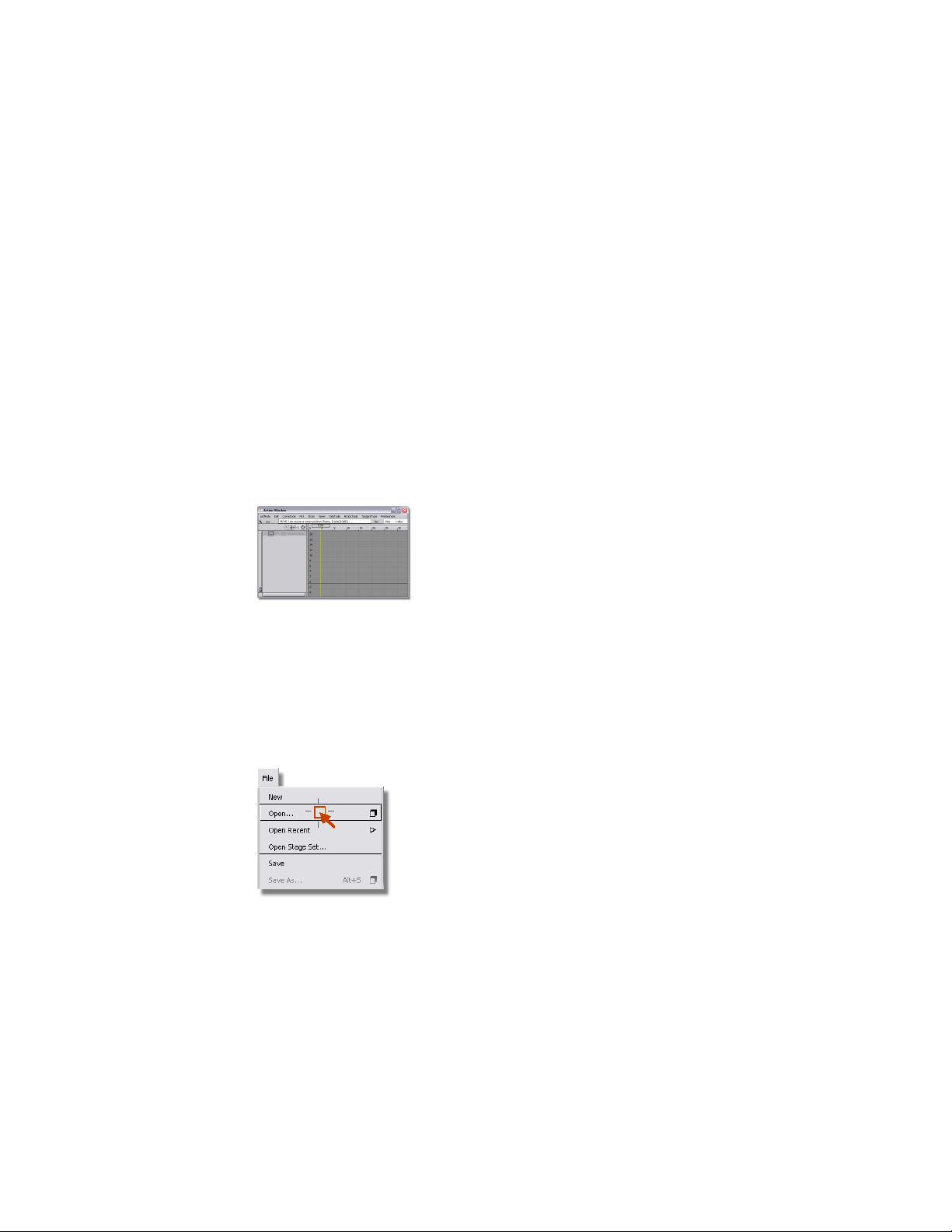
Graphic Conventions
To call attention to part of a screen shot, we highlight the important area and
darken the rest of the image. For example, in the following picture, we have
marked the location of the close box on the Action Window.
To indicate a click, we use this symbol. For example, in the following picture
we have indicated that the Open command should be clicked. In the text of
the instruction, we will refer to this as File > Open. The first word or term is
the name of the menu or palette; it is followed by an arrow and the name of
the menu item or tool. In the case of a submenu, two arrows are used: Layouts
> All Windows > All Windows refers to the All Windows menu item
available from the All Windows sub-menu, which is found on the Layouts
menu.
To indicate that an option box for a tool or menu item should be opened, a
box appears after the tool name, like Surfaces > Skin ❒.
4 | Chapter 1 How to use this book
Page 11

Terms
When we ask you to choose a tool, we show the tool’s icon next to the
instruction, for example, select Pick > Object .
Click: Move the mouse pointer over an object and press and release a mouse
button once.
Double-click: Move the mouse pointer over an object and press and release a
mouse button twice fast.
Drag: Move the mouse pointer over an object and hold down a mouse button,
then move the mouse with the button held down. Then release the mouse
button.
Click-Drag: Move the mouse pointer over an object, press the mouse button,
and move the mouse pointer to a final position before releasing the mouse
button.
The Scene: The 3D “world” inside the view windows.
The Model: The curves, surfaces, and points that make up the object you are
creating.
Terms | 5
Page 12

6
Page 13

Getting help on Alias
2
Autodesk provides you with a number of resources to aid you in becoming a proficient Alias
user.
Finding help on Alias features
Try thisIf:
You want information about installing Alias
You are new to Alias
■ Follow the on-screen instructions on
the installation DVD. For more detailed
instructions, see the InstallingAlias.pdf
file on the top level of the DVD.
■ Read Getting Started, the booklet included in the kit.
■ Browse through the information on
the main documentation page (index.html).
■ Work through these tutorials in Learning Alias. These are basic lessons that
will teach you about working in 3D in
Alias. They are also the prerequisite for
more advanced Alias courses.
■ Use the How To… section of the online
documentation to learn how to perform specific operations within Alias,
like drawing curves, making four-sided
7
Page 14

surfaces, and using masks while painting.
■ Visit http://www.autodesk.com/estore
to find out about learning tools.
You are upgrading from a previous version
of Alias
You are looking for detailed information
about a tool or feature
You want to learn new techniques for using
Alias
■ See the What’s New in Alias document,
available by selecting Help > What’s
New, or available as a PDF file on the
Alias Design Community Web site ht-
tp://aliasdesign.autodesk.com.
■ Look at the What’s New tab in the
default shelf provided with the application.
■ Look in the “Tool Palettes” and
“Menus” sections of the online help.
■ Choose Help > What’s This and
then click the tool or menu item.
■ Use the right mouse button on the
background of any option window to
see help for that tool or operation.
■ See “Learning Alias”.
■ See “Learning Technical Surfacing.”
■ Go to the Communities section of ht-
tp://www.autodesk.com, and check out
the tips and tricks.
■ Visit http://www.autodesk.com/estore
to find learning tools aimed at intermediate and advanced users.
You want a PDF version of one of the
manuals
8 | Chapter 2 Getting help on Alias
■ All of the manuals are available in PDF
format on the Alias Design Community
Web site http://ali-
asdesign.autodesk.com..
Page 15

You want to know what the keyboard
shortcuts are in Alias
■ Choose Help > Modifier Keys from
within Alias, or click Help > Modifier
Keys, Marking Menu Keys, and Hotkeys
on the main online help page.
You want a Quick Reference card
Finding Alias training resources
You want to obtain in-depth training
You want to get tips and techniques from
the experts at Alias MasterClasses
You want to create plug-ins for Alias
■ Print the Quick Reference card PDF file
provided on the Alias Design Community Web site http://ali-
asdesign.autodesk.com.
Try this…If...
■ See the learning materials and training
courses available from Autodesk, see
http://www.autodesk.com/training.
■ For events near you, see ht-
tp://www.autodesk.com/training.
■ Use the Alias Application Programmers’
Interface Manual to learn the objectoriented programming required to
build plug-ins.
You want information about becoming an
Alias-certified instructor
■ See the information at ht-
tp://www.autodesk.com/training or
contact us at learningtools@autodesk.com.
Finding Alias training resources | 9
Page 16

Finding support for Alias
Try thisIf…
You are a Platinum member and want to
access the Knowledgebase or Ask Autodesk
You want to interact with other Alias users
You want answers to common
troubleshooting questions
You want to license your software
■ Go to the Alias support site at ht-
tp://www.autodesk.com/support
■ Go to the online User-to-User Discussion forum on the Alias support site at
http://www.autodesk.com/support
■ See the FAQs (frequently asked questions) in the technical support section
of the Alias support website at ht-
tp://www.autodesk.com/support.
■ If you are a Platinum member and
need a license, check the executable
license file on the top of your installation DVD. If your license isn’t there, go
to http://www.autodesk.com/spar and
follow the instructions in the InstallingAlias.pdf file at the top of the Alias
DVD.
■ If you are a new customer, go to ht-
tp://www.autodesk.com/opa to obtain
a new license.
You want customer or technical support
10 | Chapter 2 Getting help on Alias
■ Go to the webpage ht-
tp://www.autodesk.com/support.
Page 17

Working with Alias
If you create concept designs
■ Read about our concept design workflow
■ Work through the modeling and rendering tutorials in Learning Alias
If you build 3D models based on sketches
■ Work through the modeling tutorials in Learning Alias
If you build 3D models for manufacture
■ Read About Curves and About Modeling
■ Work through the modeling tutorials in Learning Alias
■ Check the community site for tips and tricks
If you modify 3D models for manufacture
■ Read Alias Fundamentals
■ Work through the Learning Technical Surfacing tutorials
If you create rendered images
■ Read About Rendering
■ Work through the rendering tutorials in Learning Alias
■ Check the community site for tips and tricks and downloadable shaders
and backgrounds
If you create animations
■ Do the work in the “If you create rendered images” section
■ Read About Animating
■ Work through the animation tutorials in Learning Alias
Working with Alias | 11
Page 18

■ Check the community site for tips and tricks
12 | Chapter 2 Getting help on Alias
Page 19

Interface Basics
Learning objectives
You will learn how to:
■ Log into the system and start Alias.
■ Arrange windows.
■ Use tools and tool options.
■ Customize shelves and marking menus.
■ Tumble, track, and dolly the view.
■ Use the Object Lister window to understand the model.
3
Introduction
Before you begin working in Alias, you should spend some time learning how
Alias represents the scene and the model (both externally and internally), and
how you use menus and tools to create and edit model data.
Installing the tutorial courseware files
Each tutorial in this book is based on an Alias wire file, which contains the
material you need to learn the tools, skills, and concepts in the tutorial. These
files are required to complete the Learning Alias and Technical Surfacing
tutorials.
13
Page 20

When you install Alias, the courseware files (Alias wire files and other support
files) are not automatically installed. You must install them manually.
To install the courseware for use with Alias
The courseware files (Alias wire files and other support files) are not
automatically installed when you install the documentation from the Alias
Installation DVD.
1 Download the courseware files from the Alias Design Community Web
site http://aliasdesign.autodesk.com.
NOTE You need write permissions to the directory in which you plan to install
the courseware files.
2 Copy the downloaded CourseWare folder into your user_data folder.
On Windows systems, this is typically:
C:\Documents and Settings\[userid]\My Documents\Autodesk\Ali
as\user_data\CourseWare
On Mac OS X, this is typically:
/Documents/Autodesk/Alias/user_data/CourseWare
Starting Alias
Logging In
If you have not logged in to your account on your workstation, do so now.
To log in to your account
■ Type your user name and password at the prompts.
If you have an account on this workstation, the operating system user
environment appears.
Depending on which product you are using, the Alias icon may have a different
name, such as Design or Automotive.
14 | Chapter 3 Interface Basics
Page 21

To start Alias on Windows
1 Do one of the following:
■ Double-click the Alias 2010 shortcut icon on the desktop
■ Select Programs > Autodesk > Alias 2010 > Alias from the Start
menu.
If you work in an environment where there are several Alias products
installed, the first time you run Alias, you may be presented with a choice
of products to launch. The product choice depends on the licenses owned
by your organization.
2 Choose the product you want to run, and click Go.
If you select Surface or Design, skip to step 4#.
If you selected the Automotive product, you are presented with a
workflow selection.
3 For the purpose of these tutorials, choose the Default workflow, which
gives you access to all 3D curve and surface creation tools.
The Paint workflow is for working solely within a 2D environment. You
can click the do not show again check box, so this window will not
appear every time you launch Alias. If you have chosen a workflow setting
and checked don’t show again, you can change the default workflow
by choosing the workflow you want from Preferences > Workflows.
Alias launches the application in the same workflow that was active when
you last exited the application.
4 Alias shows a splash window as it loads.
During start-up, Alias may warn you about unusual conditions on your
system:
If you are already running Alias (or if Alias exited abnormally the last
time you ran it), the application asks you if you really want to start
another copy.
If you are sure Alias is not running, click Yes to continue loading.
5 After Alias has finished loading its resources and plug-ins, the workspace
window opens.
To start Alias on Mac OS X
1 Do one of the following:
■ Double-click the Alias 2010 shortcut icon on the desktop
Starting Alias | 15
Page 22

■ Click the Alias icon on the Dock.
■ From the Apple Finder, select Go > Applications, browse to
Autodesk > Alias2010 and double-click Alias.
If you work in an environment where there are several Alias products
installed, the first time you run Alias, you may be presented with a choice
of product to launch. The product choice depends on the licenses owned
by your organization.
2 Choose the product you want to run, and click Go.
If you select Surface or Design, skip to step 4#.
If you selected the Automotive product, you are presented with a
workflow selection.
3 For the purpose of these tutorials, choose the Default workflow, which
gives you access to all 3D curve and surface creation tools.
The Paint workflow is for working solely within a 2D environment. You
can click the do not show again check box, so this window will not
appear every time you launch Alias. If you have chosen a workflow setting
and checked don’t show again, you can change the default workflow
by choosing the workflow you want from Preferences > Workflows.
Alias launches the application in the same workflow that was active when
you last exited the application.
4 Alias shows a splash window as it loads.
During start-up, Alias may warn you about unusual conditions on your
system:
If you are already running Alias (or if Alias exited abnormally the last
time you ran it), the application asks you if you really want to start
another copy.
If you are sure Alias is not running, click Yes to continue loading.
5 After Alias has finished loading its resources and plug-ins, the workspace
window opens.
16 | Chapter 3 Interface Basics
Page 23

Overview of the Alias Interface
The main parts of the Alias interface are:
■ the Palette (location can be customized)
■ the Menu Bar, located at the top
■ the Window Area, taking up most of the interface and located in the
middle (this area may or may not contain view windows when you first
start Alias).
■ the Shelves (location can be customized)
■ the Control Panel, located on the right
If the Palette or Shelves are not visible, choose Windows > Palette... or
Window > Shelves... from the Menu Bar.
The position of the Palette and Shelves can be customized from the options
in Preferences > Interface > Palette/Shelves Layout ❒. In the following tutorials,
we will work with the Palette on the Left and the Shelves on the Bottom
Overview of the Alias Interface | 17
Page 24

of the interface. (To learn how to set options see Set options for a tool or menu
item.)
As you continue through this tutorial, you will become more and more familiar
with the Alias interface.
Using Help
One of the most important menus is the Help menu. The Help menu is
organized so you can get quick and specific information on just about any
tool in Alias.
To get help on a tool or menu item
It is easy to get help on any tool or menu item in the interface using the
following steps.
1 Click the Help menu, located at the right end of the menu bar.
2 In the Help menu, click What’s This?
3 Click a menu item or a tool icon in the Palette.
You are prompted to select the tool for which you want help. (This prompt
appears in the prompt line, located just below the menu bar.)
A browser window launches and the on-line documentation about that
tool icon or menu item displays.
4 When you are finished reading the information, minimize or close the
browser window.
Arranging Windows
Performing Menu Commands
To use the menus to choose a window layout
1 Click the Layouts menu to open the menu.
NOTE Notice the arrow next to the All Windows command. This means
there are suboptions for this command:
18 | Chapter 3 Interface Basics
Page 25
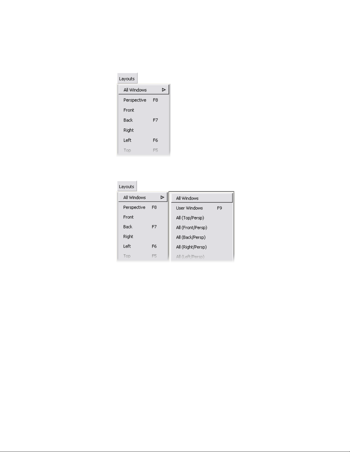
2 Click the All Windows command to open the submenu, then click the
All Windows option.
The All Windows command arranges view windows in the following
layout: Top, Left, Back, and Perspective.
Arranging Windows | 19
Page 26
These tutorials sometimes refer to menu options by the path through the
menus to the item. So, All Windows is: Layouts > All Windows > All
Windows .
As an alternative to the single-click method, you can use the pull-down
menus by dragging the mouse down the menu and releasing on the
option you want.
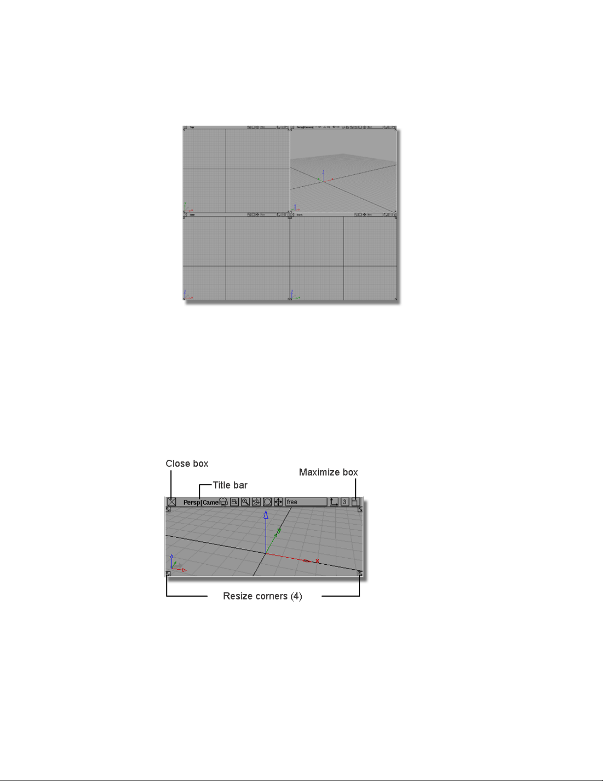
Window Controls
Use these controls on the borders of view windows to move, close, and resize
the window:
20 | Chapter 3 Interface Basics
Page 27
The view windows have more controls across the top, but for now, concentrate
on the close box, title bar, maximize, and resize corners.
You will discover the functions of the other icons later in the tutorials.
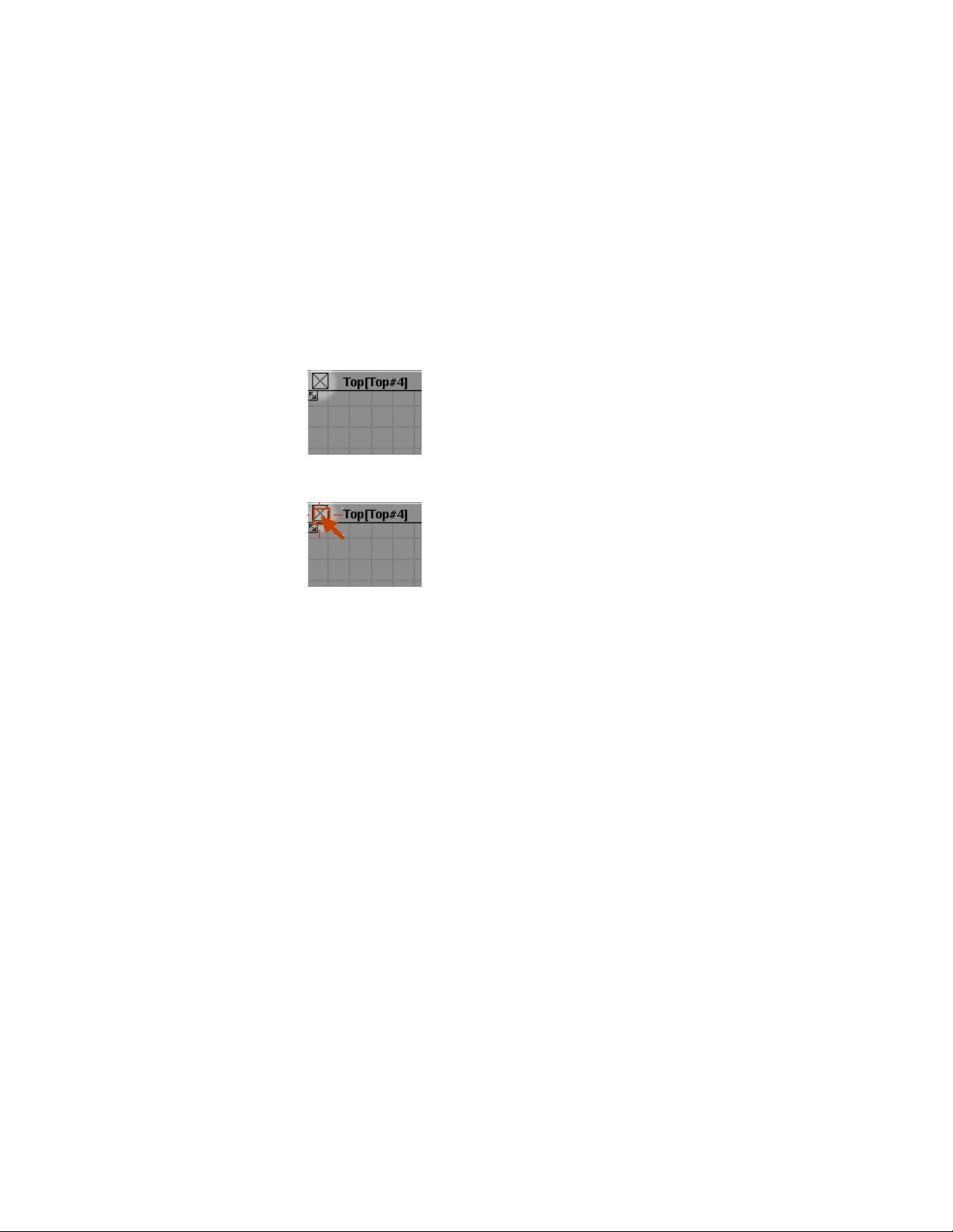
Closing Windows
To close the Top view using the close box
■ Find the close box in the upper left corner of the Top view window.
■ Click the Top view window close box.
The Top view window disappears.
Resizing Windows
You can change the size of windows using the resize arrows at each corner.
To change the size of a view window using the resize arrows and maximize
box
1 Find the resize arrows in the corners of a view window.
Arranging Windows | 21
Page 28
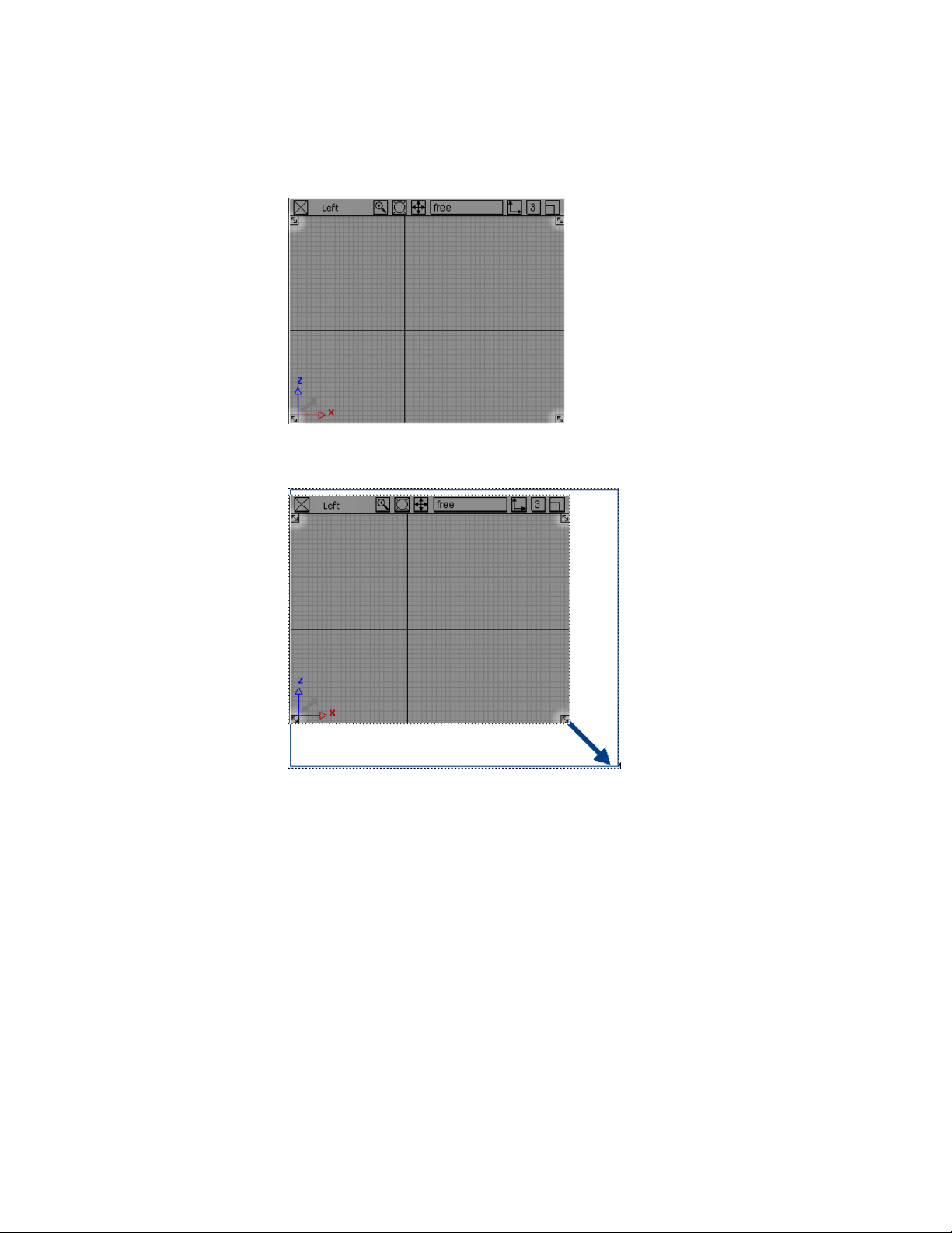
2 Drag a resize arrow to change the size of the window. An outline of the
view window follows the mouse.
3 Release the mouse button. The corner of the window snaps to the new
size.
4 Try dragging the resize corners in the other corners to see how they resize
the window.
■ To work in one large window to see more detail, use the maximize
box to temporarily make the view window fill the entire screen.
5 Find the maximize box in the upper right corner of a view window.
22 | Chapter 3 Interface Basics
Page 29
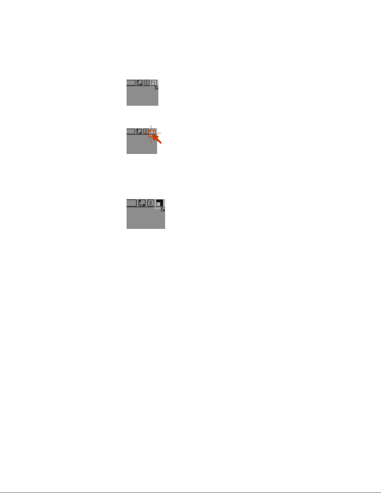
6 Click the maximize box of the view window.
The view expands to fill the entire screen.
Notice that the maximize box changes to black to show the window is
maximized.
7 Click the maximize box again to return the view window to normal size.
Moving Windows
To move and arrange the remaining windows
1 Find a view window’s title bar.
The title bar is the area at the top of the window, between the close box
and the other icons on the right.
2 Drag the title bar. An outline of the view window follows the mouse.
Arranging Windows | 23
Page 30
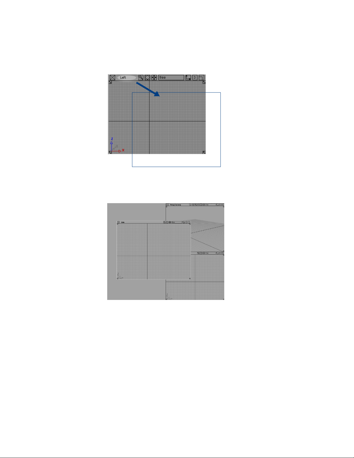
3 Release the mouse button. The window snaps to the new location.
4 By now you probably have some view windows overlapping other
windows, similar to this:
The windows are like a stack of papers on a desk. As you shuffle them,
they can overlap.
24 | Chapter 3 Interface Basics
Page 31

When windows overlap like this, you can click in a window to move that
window to the front of the stack.
5 Click the title bar of the Perspective view window to move it in front of
the other windows.
The windows are probably a little disorganized at this point. Quickly reset
them to a default layout using the commands in the Layout menu again.
6 Choose Layouts > All Windows > All Windows .
The Active Window
Notice one of the view windows has a white border. This is how Alias indicates
the active view window (sometimes also called the current view window).
Arranging Windows | 25
Page 32

The active view window is always the last view window you clicked in.
Some tools change behavior based on which view is active, but for now you
can disregard which view window is active.
Saving an arrangement of windows
If you have a particular choice of windows that you plan to use repeatedly,
you can save the set by choosing Layouts > User Windows > Save Current
Layout . You are prompted for a file name. To use this layout in the future,
choose Layouts > User Windows > Retrieve Layout .
Using Tools
Describes how to use the Alias interface, such as selecting tools and creating shortcuts.
Tool Basics
To orient yourself in the Palette window
1 Find the Palette window floating on the left side of the screen.
If the palette is not visible, go to the Windows menu and choose
Palette.
26 | Chapter 3 Interface Basics
Page 33

The Palette window is divided into separate palettes of tools, each labeled
with a tab at the top.
For example, the Curves palette contains tools for creating new curves.
The Curve Edit palette contains tools for editing and reshaping existing
curves.
2 Find the Surfaces palette. It is the eighth palette from the top of the
window.
NOTE If you cannot see the Surfaces palette, use the scroll bar on the left
side of the palette window to scroll up or down until it is visible in the window.
3 Hold the cursor over a tool.
The name of the tool appears in a small box just below the icon. This
small text window is called a tooltip.
This feature can help you to identify tools until you become familiar with
the icons in the palette.
NOTE Once you are familiar with the icons in the palette, you may want to
disable tooltips. To do this, select the Tooltips option in the Interface
section of the General Preferences window (Preferences > General
Preferences ❒).
Tool Basics | 27
Page 34

Now use the geometric primitive tools to add some geometry to the scene.
The primitive tools create simple 3D geometric shapes such as cubes, spheres,
and cones.
As a technical surfacer, you may not regularly need to add these simple shapes
to a model. However, they allow you to practice several Alias interface concepts,
including choosing tools, using manipulators, subpalettes, tool option
windows, and snapping.
To create a primitive sphere in the scene
1 Click the Surfaces > Primitives > Sphere tool.
2 A red outline appears around the icon to show it is the current tool.
3 Click in the Top view window to place the new sphere.
A new sphere, one grid unit wide, appears where you release the mouse
button.
Using a Snap Mode
To use grid snapping to place a primitive cube
You may have noticed that some tools have a small yellow arrow in the top
right corner.
28 | Chapter 3 Interface Basics
Page 35

This arrow indicates that more, similar tools are available in a hidden
subpalette. To access the extra tools, click and hold the mouse to open the
subpalette.
1 In the Surfaces palette, click and hold the Sphere tool icon.
2 The Surfaces > Primitives subpalette appears.
3 Hold the middle mouse button on the different tools in the subpalette to
see their names.
4 Click the Cube tool.
The subpalette disappears. The Cube tool is selected and now occupies
the space in the main palette where the Sphere tool was.
This time place the new primitive using grid snapping.
5 Find the snap buttons, to the right of the promptline.
6 Click the Grid button to turn on grid snapping.
7 Click and drag in the Top view window.
Using a Snap Mode | 29
Page 36

The cube snaps to the grid intersections as you drag.
8 Place the cube at a grid point by releasing the mouse button.
9 Click the Grid snap button again to turn grid snapping off.
NOTE In addition to using the Grid button, you can grid snap by pressing
and holding the Alt (Windows) or Command (Mac) key while you place a
primitive.
To use the palette menu to choose the Cone tool
This time use an alternative method for choosing tools from palettes.
1 Click the tab at the top of the Surfaces palette.
The palette collapses to just the tab, and the other palettes move up to
fill the space.
This feature is very useful for saving space in the palette window and in
shelves. You can still choose tools from the palette using the palette’s
menu.
2 Click the right mouse button on the Surfaces palette’s title tab to open
the palette’s menu.
3 Click the Primitives option to open the submenu.
Just like the menus at the top of the screen, arrows indicate that an item
in the palette menu has subitems.
30 | Chapter 3 Interface Basics
Page 37

4 Click the Cone tool option.
You have now seen two different ways to choose a tool from a palette.
From now on, when instructed to choose tools by name, for example:
“On the Surfaces palette, choose Primitives > Cone.”
you can either click the tool icon, or choose the tool from the palette
menu.
5 Click in the Top view to place a cone in the scene.
6 Click the Surfaces palette’s tab again to expand the Surfaces palette
back to normal.
To use tool options to add a half-cylinder
1 With the right mouse button, click the title tab of the Surfaces palette to
open the palette menu, then open the Primitives submenu.
Notice that some items have shadowed boxes next to the name of the
item.
Using a Snap Mode | 31
Page 38

2 Click the shadowed box next to the Cylinder item.
3 The Cylinder options window appears.
4 Double-click in the text box labeled Sweep, then type 180 and press
Enter (Windows) or Return (Mac) to set the sweep to 180 degrees.
5 Use the slider next to the Sections text box to set the sections to 4.
6 Click the Go button at the bottom of the window.
This button applies the settings in the window and activates the tool.
7 Click in the Top view window to place the new half-cylinder in the scene.
32 | Chapter 3 Interface Basics
Page 39

As you specified in the option window, the cylinder has a 180-degree
perimeter and is created from four sections (spans).
8 Look at the Cylinder tool icon. It has a small option box symbol in the
top left corner.
Like the symbol in the menu, this indicates the tool has options.
9 Double-click the Cylinder tool icon.
The Cylinder Options window appears.
10 Click Exit to close the options window.
Picking and Unpicking Objects
Picking refers to selecting objects in the scene for use with other tools. For
example, to move a CV, you must pick the CV, then use the Move tool on
the picked CV.
Picking objects in the scene is a fundamental part of modeling with Alias.
Because it is so important, Alias provides several different tools for picking.
To pick all and pick nothing
1 In the Pick palette, choose Object Types > All Objects/Lights .
2 All the objects in the scene highlight to show they are picked.
Picking and Unpicking Objects | 33
Page 40

Unlike most selection tools, Pick > Object Types > All Objects/Lights
does not stay selected, since you never need to use it twice in a row.
When these momentary types of tools finish, the current tool reverts to
the last continuous tool you selected.
3 In the Pick palette, choose the Nothing tool.
4 The Pick > Nothing tool unpicks every object, leaving nothing picked.
Like the Pick > Object Types > All Objects/Lights tool, the Pick >
Nothing tool does not stay selected. The current tool reverts to the last
tool you used.
To pick and unpick individual objects
1 Choose the Pick > Object tool.
34 | Chapter 3 Interface Basics
Page 41

2 Click the cone primitive in the view windows with the left mouse button.
The cone highlights to show it is picked.
3 Click the other objects with the left mouse button. They also become picked.
4 With all the objects picked, click one of the picked objects with the left
mouse button.
Picking and Unpicking Objects | 35
Page 42

The object you clicked becomes unpicked.
The left mouse button toggles objects between picked and unpicked.
5 Now click one of the primitives with the middle mouse button.
The object you clicked is picked and the other objects are unpicked.
The middle mouse button picks only the object you click.
6 Click the picked primitive with the right mouse button.
36 | Chapter 3 Interface Basics
Page 43

The object is unpicked.
The right mouse button unpicks objects. This is most useful with pick boxes,
as you will see in the next procedure.
To use pick boxes to pick and unpick several objects at once
1 With the Pick > Object tool still selected, click one of the primitive objects
with the left mouse button.
2 Press the left mouse button and drag a box around all the primitive objects.
Picking and Unpicking Objects | 37
Page 44

All the objects inside the pick box toggle between picked and unpicked.
3 Now drag a pick box with the middle mouse button around some objects.
38 | Chapter 3 Interface Basics
Page 45

Now only the objects inside the box are picked.
4 Now drag a pick box with the right mouse button around some of the
picked objects.
Any objects inside the pick box are unpicked.
To pick by name
1 Use the middle mouse button to pick only the sphere.
2 On the Windows menu, choose Information
> Information Window.
The Information window appears.
Picking and Unpicking Objects | 39
Page 46

The information window allows you to adjust parameters for objects in
the scene.
3 Find the Name field. The name of the object should be sphere or
something similar.
4 Close the Information window.
5 Click in empty space with the middle mouse button.
All objects in the scene are unpicked.
■ Remember, the middle mouse button picks only what you click. If
you pick “nothing” (empty space), then the tool acts as if you had
chosen Pick > Nothing .
6 Type sphere, then press Enter (Windows) or Return (Mac). The text appears
as you type in the promptline at the top of the workspace window.
When you press Enter (Windows) or Return (Mac), the sphere is picked.
Shortcuts to Tools
The variety of tools available is the source of Alias’s power, but finding tools
in the palette can become potentially time consuming. You can make
commonly used tools available more quickly, and hide rarely used tools until
you need them.
Alias provides three solutions: shelves, marking menus, and hotkeys.
40 | Chapter 3 Interface Basics
Page 47

Shelves are like the palettes, except you control the tools’ options and their
position on the shelves. You use shelves to organize all your commonly used
tools.
Marking menus appear at the current mouse location. They provide a very
fast method to choose the tools you use most often (such as Pick > Object ).
Hotkeys are special key combinations that perform common menu or tool
commands.
Creating Custom Shelves
To show and hide the shelf window
1 On the Windows menu, choose Shelves.
The Shelves window appears.
■ The Shelves window provides a floating window in which to keep
commonly used tools.
Alias, however, provides another, even more convenient location for
shelves. In these tutorials, you will use the shelf area in the control
panel.
■ Since you will not be using the Shelves window, you can close it.
2 Choose Windows > Shelves again to hide the Shelves window, or click
the Shelves window’s close button.
To help demonstrate how to make new shelves, clear the default shelves and
make new shelves specific to these tutorials.
Before you clear the default shelves, save them, so you can retrieve them later.
To save the initial shelf set
1 Choose Windows > Control Panel. The control panel appears.
2 Hold the left mouse button on the Shelf menu button at the top of the
control panel’s shelf area to open the options menu.
Creating Custom Shelves | 41
Page 48

3 Drag down to the Save option and release the mouse button.
A file requester appears.
4 Click in the Object name text field and type Default, then click Save.
In the next procedure, you will start a new shelf of tools commonly used in
curve fitting in preparation for the lesson on fitting curves to scan data.
To clear the existing shelf set and create a new one
1 Hold the left mouse button on the menu button at the top of the shelf area
to open the options menu. Notice how the menu button is now called
Default, after the name of the current shelf.
2 Choose New from the options menu.
A requester appears asking for the name of the new shelf.
3 Click in the text box, press the Esc key to clear the text, and type CurveFit.
Click OK to name the new shelf.
42 | Chapter 3 Interface Basics
Page 49

The old Shelf set is deleted and a new, empty shelf appears in the shelf
area.
Now you can begin adding tools to the new shelf.
4 In the Palette window, find the Curve Edit palette.
5 With the middle mouse button, drag the Fit Curve tool onto the CurveFit
shelf in the control panel.
The tool appears in the shelf.
You could move the entire Curve Edit palette onto the shelf by dragging
its title tab, but you only want a selection of tools from the full palette.
Next, add curve drawing tools to the palette.
Since you will often need to create curves of different degree in technical
surfacing, it would be useful to have customized versions of tools with different
settings.
The shelf allows you to do this. When you drag a tool onto a shelf, the new
copy of the tool keeps the settings it had when it was dropped on the shelf,
independent of the original tool in the palette.
Using this technique, create several versions of the two original curve creation
tools, New curve (edit pts ) and New curve (cvs) .
For each version, assign different settings for the Degree option.
To add versions of the New curve tools to the shelf with different options
1 In the Curves palette, double-click New Curves > New Edit Point
Curve and open the tool’s option window.
2 (Remember that you can also choose New Edit Point Curve from the
palette menu).
The New Edit Point Curve option window appears.
Creating Custom Shelves | 43
Page 50

The options let you set the knot spacing (parameterization) and degree
of the new curve.
3 Make sure Knot Spacing is set to Uniform and Create Guidelines
is off.
4 Set the Degree option to 2.
5 Find the tool icon at the top of the option window.
This icon represents the tool as configured with these settings.
6 Press the middle mouse button on the tool icon at the top of the option
box and drag it to the CurveFit shelf.
44 | Chapter 3 Interface Basics
Page 51

Now when you choose this icon in the shelf, the New Curve (edit pts)
tool creates degree 2 curves.
7 Back in the option window, set the Degree to 3.
8 Use the middle mouse button to drag the tool icon at the top of the option
window to the shelf.
Another copy of the tool is added to the shelf. When you choose this
copy of the tool, the New Curve (edit pts) tool will create degree 3
curves.
9 Click Exit at the bottom of the option window to close the window.
To rename the tools
1 Move the mouse over the CurveFit shelf’s title tab and press the right
mouse button to show the shelf’s menu.
Creating Custom Shelves | 45
Page 52

Note that the two versions of the tool have the exact same name and
icon.
To be able to distinguish between the tools, rename them.
2 Find the first version of New Curve by Edit Points you dragged to the
shelf.
If you cannot remember which is which, double-click the two icons to
see their option windows. You want the version with the Degree option
set to 2.
3 Hold down the Ctrl (Windows) or Control (Mac) key and double-click the
tool icon.
A name requester appears.
4 Double-click in the text box and type Edit_pt_Deg_2, then click OK to
rename the tool.
5 Hold down the Ctrl (Windows) or Control (Mac) key and double-click the
second copy of the New Curve by Edit Points tool.
6 Double-click in the text box and type Edit_pt_Deg_3, then click OK to
rename the tool.
7 Hold down the right mouse button on the title tab of the shelf to open the
shelf menu.
The two copies of the tool are now distinguishable in the menu, but still
have identical icons.
We recommend you keep the shelves collapsed and use the shelf menus
to choose tools. This saves space in the shelf.
46 | Chapter 3 Interface Basics
Page 53

To remove a tool from the shelf
1 Add another tool to the CurveFit shelf.
Let’s now assume that this was a mistake and you want to remove the
tool.
2 Hold the middle mouse button over the tool’s icon in the shelf.
The name of the tool appears.
3 With the middle mouse button held down, drag the label to the upper-right
corner of the window and position the cursor over the trash can icon.
4 Release the mouse button. The tool disappears from the shelf.
You can also delete groups of tools by dragging a tab with the middle
mouse button to the trash can.
You may have noticed that icons are a bit crowded on the shelf. The large
icons are good when you are learning which icon is which, but now you can
switch to the small icon size to save space in the shelf.
To change to the small icon size
1 In the Preferences menu, choose General Preferences ❒. The
Interface options appear.
Creating Custom Shelves | 47
Page 54

2 Set the Tool Icons to Small.
If you want, you can also turn on the icon labels option to display name
labels for all the icons.
3 Click the Go button at the bottom of the window to apply the changes.
Alias loads smaller versions of all the tool icons.
You have seen how to create shelves with customized tools. In later lessons,
you will load pre-made shelves containing all the tools you need to complete
the tutorials.
Using and Customizing Marking Menus
An even faster method for selecting tools is the marking menus. Marking
menus generally hold fewer tools than a shelf, but are much faster since you
can use quick gestures to choose tools. With practice, selecting tools with
marking menus becomes almost instantaneous.
48 | Chapter 3 Interface Basics
Page 55

To choose common tools with marking menus
1 Hold down the Shift and Ctrl (Windows) or Shift and Control (Mac) keys.
2 With the keys held down, hold the left mouse button.
The left mouse button marking menu appears at the location of the mouse
pointer.
3 Keep the left mouse button held down and drag down until the Pick >
Object box is highlighted.
A thick black line shows the direction of the mouse pointer.
4 Release the mouse button to choose the highlighted tool.
The Pick > Object tool is now the current tool.
5 Hold Shift and Ctrl (Windows) or Shift and Control (Mac) with the middle,
then with the right mouse buttons to see the other marking menus.
Each mouse button has a separate marking menu.
Using and Customizing Marking Menus | 49
Page 56

Once you have learned which direction corresponds to which tool in a
marking menu, you can use a quick gesture to choose the tool.
6 Hold the Shift and Ctrl (Windows) or Shift and Control (Mac) keys, then
drag up and release the mouse button quickly.
The black line shows the direction, but the menu is not drawn.
When you release the mouse button, the marking menu flashes the name
of the selected tool on the screen.
You have just selected Pick > Nothing .
Use this method to choose tools even faster once you have mastered the
positions of the tools on the menu.
Learn which tools are on the marking menus, and use the marking menus
whenever you need to choose one of those tools. The more you use them, the
faster you will become, until you can choose tools with quick gestures.
50 | Chapter 3 Interface Basics
Page 57

To customize a marking menu with common tools
1 On the Preferences menu, open the Interface submenu and choose
Marking Menus.
The MarkingMenus shelf window appears.
This is a special shelf window. The tools and menu items on the different
tabs appear in corresponding marking menus.
The procedure to modify the content of marking menus is similar to the
one for modifying shelves that you learned earlier.
Here you will make a small modification to the Selection marking menu
shelf.
2 Click the Pick tab in the Palette (if it isn’t already expanded) and locate
the Pick > Template tool.
3 Hold down the middle mouse button on the icon and drag it to the marking
menu shelf, to the location shown in the image below.
Using and Customizing Marking Menus | 51
Page 58

4 Release the mouse button to position the icon at the location indicated
by the red arrow.
You now have a tool on the marking menu to pick templated geometry.
5 Hold down Shift and Ctrl (Windows) or Shift and Control (Mac) keys and
press the left mouse button to show the marking menu again.
52 | Chapter 3 Interface Basics
Page 59

The tool you just added is called Pick > Template in the marking menu.
Change the name to something more concise.
6 In the MarkingMenu shelf window, hold down the Ctrl (Windows) or
Control (Mac) key and double-click the Pick Template tool in the shelf.
7 A dialog box appears.
8 Type Template in the text field and click OK to rename the tool in the
marking menu.
9 Show the left mouse button marking menu again.
Using and Customizing Marking Menus | 53
Page 60

You now know how to customize the marking menus. In later lessons, you
will load pre-made marking menus with common surfacing tools.
Using hotkeys
Hotkeys are special key combinations that choose tools or perform menu
commands. You can get a complete listing of all the hotkeys in the hotkey
editor.
To use hotkeys
1 On the Preferences menu, click Interface and choose Hotkeys/Menu
Editor.
The hotkey editor appears.
54 | Chapter 3 Interface Basics
Page 61

■ Alias’ s option windows use a hierarchy similar to that of the File Lister:
options are organized into hierarchical sections that can be collapsed
and expanded.
2 In the Menu section, click the Layouts subsection title to expand it.
Click to open a Section Heading.
You can see the hotkey for the User windows item, as well as text fields
for defining other hotkeys.
Using hotkeys | 55
Page 62

You can define your own hotkeys, if you want. For the most part, you
will not use hotkeys in these lessons.
If you are new to Autodesk Alias products, we recommend that you spend
some time working with the product before you define hotkeys, so you
can learn which commands you use frequently enough to need a hotkey.
3 Click the close box to close the hotkey editor.
Changing Your View of the Model
Learn how Alias represents the 3D model on your 2D monitor, and how to use the
view controls to get the best possible angle on the model for the task at hand.
Tracking, Dollying, and Tumbling the Camera’s View
There are many different ways to change the camera’s view in Alias.
In general, you only need to learn three camera moves to model effectively:
tumble, dolly, and track.
56 | Chapter 3 Interface Basics
Page 63

Because these camera movements are so common, Alias uses special
hotkey/mouse combinations to access these movements quickly.
To use the camera move mode to move the camera in a perspective window
1 Hold down the Shift and Alt (Windows) or Shift and Command (Mac) keys.
Keep the keys held down during the following steps.
2 Make sure the mouse pointer is over the perspective view window.
Tracking, Dollying, and Tumbling the Camera’s View | 57
Page 64

3 Drag the left mouse button to tumble the camera:
■ Drag left and right to rotate the camera.
■ Drag up and down to tilt the camera.
Tumbling the camera changes the azimuth and elevation angles of the
camera.
4 Release the left mouse button, but keep the Shift and Alt (Windows) or Shift
and Command (Mac) keys held down.
5 Drag the right mouse button to dolly the camera in and out.
58 | Chapter 3 Interface Basics
Page 65

Dollying moves the camera forward and backward.
6 Again, release the right mouse button, but keep the Shift and Alt (Windows)
or Shift and Command (Mac) keys held down.
7 Drag the middle mouse button to track the camera.
Tracking moves the camera, but does not change the direction in which
the camera is pointing.
8 When you are done moving the camera, release the mouse button and
the Shift and Alt (Windows) or Shift and Command (Mac) keys to exit camera
move mode.
Tracking, Dollying, and Tumbling the Camera’s View | 59
Page 66

Now, try moving the camera in the orthographic windows.
To use the camera move keys to move the camera in an orthographic window
1 Hold the Shift and Alt (Windows) or Shift and Command (Mac) keys to enter
camera move mode.
2 Make sure the pointer is over an orthographic window such as Top, Side,
or Back.
3 Drag the right mouse button to dolly in and out.
4 Drag the middle mouse button to track up, down, left and right.
60 | Chapter 3 Interface Basics
Page 67

5 Now try dragging the left mouse button to tumble the orthographic view.
Nothing happens. You cannot change the view direction of orthographic
windows. They always look in the same direction.
Moving the camera is a very important skill in Alias. Throughout these lessons,
you need to move the camera to work with geometry.
Using the camera move mode soon becomes second nature. With practice,
you will be able to move the camera where you need it without thinking about
the keys or the mouse.
Practice tumbling, tracking, and dollying the camera around the model some
more before you move on.
To use Look At to center on an object
1 Use the marking menus to choose the Pick > Nothing tool.
2 Remember that the left mouse button marking menu has the pick tools.
3 Now use the marking menus to choose the Pick > Object tool.
4 Pick one of the geometric objects you created earlier.
Tracking, Dollying, and Tumbling the Camera’s View | 61
Page 68

5 Find the View palette. It is near the bottom of the Palette window.
6 Choose the Look At tool.
7 The active view window (the window with the white outline) changes
to center on the picked object.
8 Pick nothing .
9 Use the Look At tool again.
10 The active view changes to center on all the existing geometry.
62 | Chapter 3 Interface Basics
Page 69

When you use Look At with nothing or everything picked, the view
centers on all the geometry in the scene.
Look At is most useful to quickly find geometry that is outside the view of
a window or too far to be seen clearly. Alias provides two additional tools to
make it easier to move the camera around a model quickly: the “point of
interest” and Viewing Panel.
Changing the Point of Interest
Normally, camera move mode (Shift+Alt (Windows) or Shift+Command (Mac))
is calibrated to best view objects at the origin (the center of world space,
coordinate 0,0,0). This can become awkward when you want to move the
camera around objects away from the origin.
The point of interest manipulator lets you center the camera movements on
a point on the model.
To use the point of interest manipulator
First, make sure the point of interest manipulator is turned on.
1 Choose Preferences > General Preferences ❒.
The General Preferences window appears.
2 Click Viewing on the left-hand side to open the Viewing section.
3 Turn on the Use point of interest option.
Changing the Point of Interest | 63
Page 70

4 Change the View Control setting to Viewing Panel.
The ViewCube is the default view control, but we will use the Viewing
Panel in these tutorials. The ViewCube and NavBar provide the same
functionality as the Viewing Panel. For information, see Use the ViewCube
tool and NavBar.
NOTE The point of interest manipulator works the same for both the Viewing
Panel and the ViewCube and NavBar.
5 Click Go to close the window and use the new settings.
6 Hold down the Shift and Alt (Windows) or Shift and Command (Mac) keys
to enter camera move mode. Keep the keys held down for the rest of this
procedure.
The Viewing Panel appears in the upper left corner of the Perspective
window.
7 Position the mouse pointer on the wireframe of one of the primitive
objects and double-click with the left mouse button.
When you release the mouse button, the point of interest manipulator
appears on the model where you clicked.
64 | Chapter 3 Interface Basics
Page 71

Drag with the left mouse button to tumble. The view tumbles around the
point of interest.
8 Click and release on another point on one of the primitive objects.
The point of interest manipulator jumps to the new point.
9 Drag the circle at the center of the point of interest manipulator.
The manipulator moves across the surface of the object.
10 Notice the light blue or yellow arrow extending from the center of the
manipulator. This arrow indicates the normal at this point on the surface.
The arrow is light blue when it is pointing toward you and yellow when
pointing away.
11 Click the light blue or yellow arrow.
The view changes to look at the point down the normal.
12 Now look for the red and green arrows extending from the center of the
manipulator (tumble the view to show the arrows more clearly, if
necessary).
These arrows represent the tangents along the U and V directions of the
object.
13 Click the red arrow.
The view changes to look down the tangent in the U direction.
Changing the Point of Interest | 65
Page 72

Use the following overview illustration as a reminder of the different controls
on the point of interest manipulator.
66 | Chapter 3 Interface Basics
Page 73

Using the Viewing Panel
The Viewing Panel appears when you enter camera move mode in the
Perspective window.The ViewCube tool and NavBar appear by default, but
you changed this setting in the previous section. This window lets you quickly
switch the Perspective window to a default or user-defined view of the model.
As you work on the model, you will probably find yourself changing the
camera view back and forth between two or more areas of interest. The
Viewing Panel lets you “bookmark” views of the model and return to those
views by clicking the name of the bookmark.
To use the Viewing Panel to move between different views
1 Click the maximize box in the upper right corner of the Perspective view
window.
The Perspective view window enlarges to full screen.
2 Open the General Preferences window and click Go.
3 Hold down the Shift and Alt (Windows) or Shift and Command (Mac) keys
to enter camera move mode. Keep the keys held down for the rest of this
procedure.
Using the Viewing Panel | 67
Page 74

The Viewing Panel appears in the upper left corner of the Perspective
window.
The images at the center of the panel (small icons of the top and bottom
of a car) represent the model.
4 Click an arrow to view the model from one of eight different directions.
The horizontal and vertical arrows represent front, side, and back views.
The diagonal arrows represent three-quarter views.
5 Click the left car icon to see a top view, or the right car icon to see a
bottom view.
68 | Chapter 3 Interface Basics
Page 75

6 Click the white arrow near the bottom of the Viewing Panel to return to
the view previous to your last camera move.
7 Click the Viewing Panel section heading at the top of the panel to
collapse the entire panel into a small heading.
Using the Viewing Panel | 69
Page 76

Use this technique to get the Viewing Panel out of the way when you
want as much viewing area as possible.
To use the Point of Interest manipulator
1 Hold down the Shift and Alt (Windows) or Shift and Command (Mac) keys,
then press the left mouse button to open the Viewing Panel. Keep the keys
held down for the rest of this procedure.
NOTE If the Viewing Panel does not appear, ensure that you are not clicking
the left mouse button before holding down Shift and Alt (Windows) or Shift
and Command (Mac) .
2 Double-click an object. This shows the manipulator and adds Pnt of
Interest to the Viewing Panel.
3 Click the arrow next to Pnt of Interest to see the options.
70 | Chapter 3 Interface Basics
Page 77

4 Turn off the manipulator by clicking the Visible check box to hide the
point of interest manipulator.
Turn the Visible check box on to show the manipulator again.
5 Turn on the Locked check box to keep the point of interest manipulator
locked at its current position.
The manipulator does not move when you click at another point or drag
its center handle. Use this option if you find you are moving the
manipulator unintentionally.
Turn the Locked check box off to free the manipulator.
6 Turn off the Perspective check box.
The perspective view changes to an isographic projection.
Using the Viewing Panel | 71
Page 78

Many people find an isographic view easier for technical modeling, since
parallel lines in the model remain parallel in the view window.
For the remainder of the tutorials, the screen shots will show isographic
views. However, feel free to turn the Perspective checkbox back on if
you prefer a perspective view.
To set and show bookmarks
1 Move the mouse pointer over the Perspective view and hold down the
Shift and Alt (Windows) or Shift and Command (Mac) keys, keeping them
held down, to enter camera move mode.
2 With Shift and Alt (Windows) or Shift and Command (Mac) still held down,
find the Bookmarks section at the bottom of the Viewing Panel.
If it is not visible, click the tag in the bottom right corner of the Viewing
Panel. It turns white and the bookmarks section appears.
3 Click the new button in the bookmarks section.
72 | Chapter 3 Interface Basics
Page 79

A new bookmark appears at the bottom of the section.
4 Move the camera to a new view on the model.
5 Click the new button again.
A second bookmark appears in the bookmark list.
6 Click the label for the first bookmark, then the second.
The view switches back and forth between the two bookmarked views.
NOTE To be able to distinguish between bookmarks later, you should rename
them now.
7 Click the edit button in the BookMarks section.
The BookMarks Lister window appears.
8 Release the Shift and Alt (Windows) or Shift and Command (Mac) keys.
Using the Viewing Panel | 73
Page 80

9 Hold down the Ctrl (Windows) or Control (Mac) key and double-click the
first bookmark icon in the Bookmark Lister.
A dialog box appears.
10 Type a new name for the bookmark, then click OK.
For production work, you should use meaningful names, such as “back
panel” or “door handle”.
NOTE By default, bookmarks are named bm, bm#2, bm#3, and so on. Move
the cursor over a bookmark icon to see its current name.
11 Ctrl (Windows) or Control (Mac) double-click and rename the other
bookmark.
12 Note the buttons in the Bookmark Lister window:
■ The Delete button removes the selected bookmarks (white outline)
from the list.
■ The New button adds a bookmark of the current view. This is the
same as clicking new in the Viewing Panel.
■ The Prev and Next buttons change the view to the bookmark that
precedes or follows the highlighted bookmark (green outline).
■ The Toggle Camera Only Mode button displays bookmarks either
with the camera view only, or with both the view and display
attributes (default).
■ The Cycle button displays the bookmarked views in a slideshow
fashion.
74 | Chapter 3 Interface Basics
Page 81

■ The Publish button saves the selected bookmarks, current shelf
bookmarks, or all bookmark(s) as image files on your disk.
■ Clicking on a bookmark icon changes the view to that bookmark.
This is the same as clicking a bookmark in the Viewing Panel.
■ Clicking the right mouse button in an empty part of the Bookmark
Lister, and choosing New shelf from the drop down menu creates
a new shelf.
13 Close the Bookmark Lister.
14 Hold the Shift and Alt (Windows) or Shift and Command (Mac) keys in the
Perspective window to show the Viewing Panel.
Notice your new names in the BookMarks section.
See also Windows > Bookmark Lister.
Use the following overview illustration as a reminder of the different controls
on the Viewing Panel.
NOTE The Twist and Azimuth/Elevation tools rotate the view around the
point of interest.
See also:
■ Use the view panel
Using the Viewing Panel | 75
Page 82

Understanding the Object Lister
Alias keeps track of every aspect of the scene in a hierarchical data structure.
You can view representations of this structure through the SBD (scene block
diagram) or through the Object Lister.
Curves, surfaces, groupings, transformations, components, lights, and
everything else in the scene is represented by nodes in the hierarchy.
You may want to use the Object Lister in the following circumstances:
■ In complex models, it can be easier to pick objects in the Object Lister
than in a view window.
■ The Object Lister shows important information that has no visual
equivalent in the view windows, such as how the components and objects
are grouped, and how they relate to modeling layers.
■ The Object Lister lets you confirm the effects of tools and menu items on
the internal structure of the scene to help diagnose problems.
Types of Nodes
Information of different types is associated with nodes in the hierarchical data
structure. These nodes can represent surfaces of different types, curves, lights,
or groups of objects.
Different types of geometry are indicated by different icons.
For a full list of icons, see Windows > Object Lister .
76 | Chapter 3 Interface Basics
Page 83

Node States
■ Grouped: you can group several objects. In the Object Lister, this is
represented by putting the objects under an orange block.
■ Instanced: you can duplicate an object as an “instance”. Instead of a new
object, an instance is just a pointer to existing geometry. It is represented
in the Object Lister as a white cube. As well, the object that has been
instanced gains a node underneath.
■ Compressed: as the Object Lister becomes busier, you may want to collapse
a part of the graph into a single node. The node with other nodes below
it has a plus sign (+) in front of it. Nodes that have been expanded and
can be collapsed have a minus sign (-) in front. Shift -click a - or + sign to
expand or compress the entire hierarchy.
■ Invisible: you can make objects in the scene invisible. Nodes for invisible
objects have gray text.
Types of Nodes | 77
Page 84

■ Templated: you can “template” objects in the scene so they are still visible,
but cannot be transformed or picked. Nodes for templated objects do not
change their appearance; however, when the object is picked, in the view
windows, it will be pink. When inactive, gray.
The Object Lister window
To view and pick using the Object Lister window
1 On the Windows menu, choose Object Lister.
The Object Lister window appears.
The graph in the window is the diagram representing the current scene.
2 Use the scroll bar on the left to move through the graph.
The nodes are labelled with their names and icons showing their types.
3 Click a geometry node in the Object Lister window.
The corresponding object in the scene becomes picked.
Pick > Object and Pick > Component
Unlike in the modeling windows, you can use either Pick > Object or Pick >
Component to select whole objects or parts of objects in the Object Lister. In
this section, you will compare picking in the modeling window with picking
in the Object Lister.
To pick using Pick > Object and Pick > Component
1 Choose Pick > Nothing .
2 In the Object Lister window, click the plus (+) sign beside the cube to
open its representation.
You can see that the cube is constructed of six planes that are grouped.
3 Choose Pick > Object and pick the cube in a view window.
4 In the Object Lister window, you can see that the grouping node is
picked.
5 Choose Pick > Component .
78 | Chapter 3 Interface Basics
Page 85

6 Find the component filter buttons to the left of the promptline. These
buttons appear when the Pick > Component tool is active.
7 Make sure the Surfaces button is pushed in.
8 Click the cube.
■ Since you must click an edge, which is shared by two sides, a small
box appears under the mouse pointer with the name of both sides.
Click the name you want.
■ The Pick > Component tool only picks one side of the cube.
In the Object Lister window, you can see that instead of picking
the entire group, the Pick > Component tool picked one of the
subnodes
9 Instead of choosing Pick > Component and having difficulties selecting
a surface that can be attached to or overlaid by another surface, you can
click the subobject directly in the Object Lister.
The Object Lister window | 79
Page 86

Conclusion
You now know how to:
■ Log into the system and start Alias.
■ Get help.
■ Arrange windows.
■ Use tools and tool options.
■ Customize shelves and marking menus.
■ Tumble, track, and dolly the view.
■ Use the Object Lister window to understand the internal representation
of the model.
80 | Chapter 3 Interface Basics
Page 87

Introduction to 3D
4
Learning Objectives
In this introductory modeling tutorial, you will start working with 3D space.
You will learn how to:
■ create primitive objects
■ duplicate objects
■ move, scale, and rotate objects
■ group and organize components
■ save files
This tutorial introduces you to working in 3D space, using the Autodesk Alias modeling
environment. You will build a desk lamp from cylinders and spheres using the Alias Surfaces
menu. As you build up the design, you will get used to moving, scaling and rotating objects
in 3D space.
You will learn how to group and organize the desk lamp, so that you can rotate the component
parts to simulate the operation of a real lamp.
Beginning a Model
Desk lamp modeling strategy
The modeling strategy for building the desk lamp model is shown below.
81
Page 88

First, you will create a base from cylinders. Then, you will build a moveable
arm at an angle, also using cylinders. Finally, you will build a lampshade using
spheres, which will then be assembled onto the arm.
As you gain experience in using Alias, choosing a modeling strategy will
become a natural part of your workflow.
To help you build the desk lamp model, an exercise file has been provided
which contains outline sketches of the design.
Opening the tutorial file
Watch how to open files and set projects.
1 Choose File > Open to open the File Browser.
82 | Chapter 4 Introduction to 3D
Page 89

The file browser window appears.
If the desklamp file is shown, jump to step 2. If not, follow the next steps
to set up the CourseWare directory.
On Windows, click the arrow next to the Go field and select Projects
to open the user_data directory.
Beginning a Model | 83
Page 90

On Mac OS X, select Projects from the Projects drop-down list to open
the user_data directory.
The projects in the user_data directory are displayed. If the CourseWare
project is not shown, refer to To install the courseware for use with Alias
on page 14.
Make the CourseWare directory the current project and open its wire
subdirectory as follows:
■ On Windows, click the CourseWare directory and choose Project >
Set Current.
84 | Chapter 4 Introduction to 3D
Page 91

■ On Mac OS X, click the CourseWare directory, click Set Current.
2 In the wire directory, choose the file desklamp and click Open.
Alternatively, double-click the file to open it.
When prompted to delete all objects, click Yes.
Beginning a Model | 85
Page 92

NOTE If your values for construction settings differ from those in the
desklamp.wire file, you are presented with a dialog box. Click Accept New
Settings to use the construction settings in desklamp.wire.
The file browser closes and the desk lamp exercise file appears in the Alias
window.
86 | Chapter 4 Introduction to 3D
Page 93

A sketch of the desk lamp design displays in the Left view. This sketch is
a reference image, known as a canvas plane. You will use it as a guide to
model the desk lamp.
If the two sketches do not appear, it is because the canvas plane display
has been turned off. To turn on canvas display, choose WindowDisplay
> Toggles > Canvas Planes .
TIP If you do not see any views, or the views do not take up the full view
window space, choose Layouts > All Windows > All Windows .
Part 1: Creating 3D objects
In this section you will create a primitive object, a cylinder, for the base of
the desk lamp.
Watch Part 1 of the tutorial.
Part 1: Creating 3D objects | 87
Page 94

Creating a Primitive Object
What are Primitives?
Primitives are ready-made objects in familiar shapes. The primitives are made
from a single surface, or a group of surfaces that form an enclosed volume.
In Alias, you can create the following primitives:
■ Sphere
■ Torus
■ Cylinder
■ Cone
■ Cube
■ Plane
Placing Primitives in views
Use the 2D views (Top, Left, and Back) to place the primitives. Which window
you choose affects which way up the primitive is created.
For example, placing a cylinder in the Top view creates a pillar.
Placing the cylinder in the Left or Back views creates a ‘fallen pillar’, or a ‘log’.
88 | Chapter 4 Introduction to 3D
Page 95

Creating the lamp stand
Now create a cylinder for the base of the lamp stand.
1 Create the first cylinder using the Top window.
Maximize the Top view.
Part 1: Creating 3D objects | 89
Page 96

2 Choose Surfaces > Primitives > Cylinder from the palette. If the palette
is not open, choose Windows > Palette from the menu bar.
3 To choose the Cylinder tool, press and hold the mouse button, so the
cursor is over the Sphere icon until the entire Primitives drawer
appears.
Then, click the Cylinder icon to choose the Cylinder tool.
The Cylinder tool is displayed in the Surfaces palette, and is outlined
in red to indicate it is the active tool.
4 You can control the exact placing of a primitive using various snapping
modes. In this section, use grid snapping to align all the cylinders centrally
on the grid origin. The grid origin is where the two dark grid lines cross.
Hold down the Alt (Windows) or Command (Mac) key to turn on grid snap
mode.
Press and hold the Alt (Windows) or Command (Mac) key near the origin.
Keep your finger held down on the Alt (Windows) or Command (Mac) key
and move the mouse until the new cylinder snaps to the correct grid
point.
90 | Chapter 4 Introduction to 3D
Page 97

Release the Alt (Windows) or Command (Mac) key and the mouse button.
5 Choose Layouts > All Windows > All Windows or press the F9 key to
display all four views, and check that the cylinder has been placed
correctly, as shown.
The cylinder remains picked, or active. Picked objects are drawn with
white lines, and objects that are not picked are drawn with dark blue
Part 1: Creating 3D objects | 91
Page 98

lines. Most tools and commands work on picked objects. Since the
Cylinder is picked, any tools or commands you choose will be applied to
it.
NOTE The cylinder has a manipulator attached to it, as do all primitives when
they are first added to the scene. The manipulator can be useful for
transforming a primitive, but is not relevant to this tutorial.
TIP To delete the cylinder, press the Delete key.
Scaling the lamp base
Next scale the cylinder to the correct size.
1 Maximize the Left view, as this is the view you will continue working
in.
2 Choose Transform > Scale .
92 | Chapter 4 Introduction to 3D
Page 99

The Scale icon is outlined in red to indicate it is the active tool. At the
same time, the cylinder’s manipulators disappear.
3 Click and drag the left mouse button to scale the cylinder equally in all
axes.
Scale the cylinder to roughly fit the width of the bottom cylinder shown
on the sketch. This forms the base of the lamp.
Part 1: Creating 3D objects | 93
Page 100

The Transform > Non-p Scale tool (non-proportional scale) modifies the
x, y or z scale of an object separately. This allows an object to be stretched
or squashed.
The mouse buttons are used to control the non-proportional scaling. For
this section, use the 2D views (Top, Side, and Back) to control the
transforms. In these views, the mouse buttons work as follows:
free transformLeft mouse button
94 | Chapter 4 Introduction to 3D
 Loading...