

Page 1

AutoCAD MEP 2010
User's Guide
March 2009
Page 2

©
2009 Autodesk, Inc. All Rights Reserved. Except as otherwise permitted by Autodesk, Inc., this publication, or parts thereof, may not be
reproduced in any form, by any method, for any purpose.
Certain materials included in this publication are reprinted with the permission of the copyright holder.
Trademarks
The following are registered trademarks or trademarks of Autodesk, Inc., in the USA and other countries: 3DEC (design/logo), 3December,
3December.com, 3ds Max, ADI, Alias, Alias (swirl design/logo), AliasStudio, Alias|Wavefront (design/logo), ATC, AUGI, AutoCAD, AutoCAD
Learning Assistance, AutoCAD LT, AutoCAD Simulator, AutoCAD SQL Extension, AutoCAD SQL Interface, Autodesk, Autodesk Envision, Autodesk
Insight, Autodesk Intent, Autodesk Inventor, Autodesk Map, Autodesk MapGuide, Autodesk Streamline, AutoLISP, AutoSnap, AutoSketch,
AutoTrack, Backdraft, Built with ObjectARX (logo), Burn, Buzzsaw, CAiCE, Can You Imagine, Character Studio, Cinestream, Civil 3D, Cleaner,
Cleaner Central, ClearScale, Colour Warper, Combustion, Communication Specification, Constructware, Content Explorer, Create>what's>Next>
(design/logo), Dancing Baby (image), DesignCenter, Design Doctor, Designer's Toolkit, DesignKids, DesignProf, DesignServer, DesignStudio,
Design|Studio (design/logo), Design Web Format, Discreet, DWF, DWG, DWG (logo), DWG Extreme, DWG TrueConvert, DWG TrueView, DXF,
Ecotect, Exposure, Extending the Design Team, Face Robot, FBX, Filmbox, Fire, Flame, Flint, FMDesktop, Freewheel, Frost, GDX Driver, Gmax,
Green Building Studio, Heads-up Design, Heidi, HumanIK, IDEA Server, i-drop, ImageModeler, iMOUT, Incinerator, Inferno, Inventor, Inventor
LT, Kaydara, Kaydara (design/logo), Kynapse, Kynogon, LandXplorer, LocationLogic, Lustre, Matchmover, Maya, Mechanical Desktop, Moonbox,
MotionBuilder, Movimento, Mudbox, NavisWorks, ObjectARX, ObjectDBX, Open Reality, Opticore, Opticore Opus, PolarSnap, PortfolioWall,
Powered with Autodesk Technology, Productstream, ProjectPoint, ProMaterials, RasterDWG, Reactor, RealDWG, Real-time Roto, REALVIZ,
Recognize, Render Queue, Retimer,Reveal, Revit, Showcase, ShowMotion, SketchBook, Smoke, Softimage, Softimage|XSI (design/logo),
SteeringWheels, Stitcher, Stone, StudioTools, Topobase, Toxik, TrustedDWG, ViewCube, Visual, Visual Construction, Visual Drainage, Visual
Landscape, Visual Survey, Visual Toolbox, Visual LISP, Voice Reality, Volo, Vtour, Wire, Wiretap, WiretapCentral, XSI, and XSI (design/logo).
The following are registered trademarks or trademarks of Autodesk Canada Co. in the USA and/or Canada and other countries:
Backburner,Multi-Master Editing, River, and Sparks.
The following are registered trademarks or trademarks of MoldflowCorp. in the USA and/or other countries: Moldflow, MPA, MPA
(design/logo),Moldflow Plastics Advisers, MPI, MPI (design/logo), Moldflow Plastics Insight,MPX, MPX (design/logo), Moldflow Plastics Xpert.
Third Party Software Program Credits
ACIS Copyright© 1989-2001 Spatial Corp. Portions Copyright© 2002 Autodesk, Inc.
Flash ® is a registered trademark of Macromedia, Inc. in the United States and/or other countries.
International CorrectSpell™ Spelling Correction System© 1995 by Lernout & Hauspie Speech Products, N.V. All rights reserved.
InstallShield™ 3.0. Copyright© 1997 InstallShield Software Corporation. All rights reserved.
PANTONE® Colors displayed in the software application or in the user documentation may not match PANTONE-identified standards. Consult
current PANTONE Color Publications for accurate color. PANTONE Color Data and/or Software shall not be copied onto another disk or into
memory unless as part of the execution of this Autodesk software product.
Portions Copyright© 1991-1996 Arthur D. Applegate. All rights reserved.
Portions of this software are based on the work of the Independent JPEG Group.
RAL DESIGN© RAL, Sankt Augustin, 2002
RAL CLASSIC© RAL, Sankt Augustin, 2002
Representation of the RAL Colors is done with the approval of RAL Deutsches Institut für Gütesicherung und Kennzeichnung e.V. (RAL German
Institute for Quality Assurance and Certification, re. Assoc.), D-53757 Sankt Augustin.
Typefaces from the Bitstream® typeface library copyright 1992.
Typefaces from Payne Loving Trust© 1996. All rights reserved.
Printed manual and help produced with Idiom WorldServer™.
WindowBlinds: DirectSkin™ OCX © Stardock
®
AnswerWorks 4.0 ©; 1997-2003 WexTech Systems, Inc. Portions of this software © Vantage-Knexys. All rights reserved.
The Director General of the Geographic Survey Institute has issued the approval for the coordinates exchange numbered TKY2JGD for Japan
Geodetic Datum 2000, also known as technical information No H1-N0.2 of the Geographic Survey Institute, to be installed and used within
this software product (Approval No.: 646 issued by GSI, April 8, 2002).
Portions of this computer program are copyright © 1995-1999 LizardTech, Inc. All rights reserved. MrSID is protected by U.S. Patent No.
5,710,835. Foreign Patents Pending.
Portions of this computer program are Copyright ©; 2000 Earth Resource Mapping, Inc.
OSTN97 © Crown Copyright 1997. All rights reserved.
OSTN02 © Crown copyright 2002. All rights reserved.
OSGM02 © Crown copyright 2002, © Ordnance Survey Ireland, 2002.
FME Objects Engine © 2005 SAFE Software. All rights reserved.
AutoCAD 2009 is produced under a license of data derived from DIC Color Guide® from Dainippon Ink and Chemicals, Inc. Copyright
Dainippon Ink and Chemicals, Inc. All rights reserved.
Government Use
Use, duplication, or disclosure by the U.S. Government is subject to restrictions as set forth in FAR 12.212 (Commercial Computer
Software-Restricted Rights) and DFAR 227.7202 (Rights in Technical Data and Computer Software), as applicable.
©
Page 3

Contents
Chapter 1 New Features in This Release . . . . . . . . . . . . . . . . . . . . . . . . . . . . . . . . . . 1
New Features for Getting Started . . . . . . . . . . . . . . . . . . . . . . . . . . . . . . . . . . . . . . 1
New Features for Drawing Electrical Systems . . . . . . . . . . . . . . . . . . . . . . . . . . . . . . . . 1
New Features for Drawing Piping Systems . . . . . . . . . . . . . . . . . . . . . . . . . . . . . . . . . 2
New Features for Drawing Radiant Heating Systems . . . . . . . . . . . . . . . . . . . . . . . . . . . . 2
New Features for Customizing Catalogs . . . . . . . . . . . . . . . . . . . . . . . . . . . . . . . . . . 3
New Features for Customizing Display . . . . . . . . . . . . . . . . . . . . . . . . . . . . . . . . . . . 3
New Features for Building Systems . . . . . . . . . . . . . . . . . . . . . . . . . . . . . . . . . . . . . 3
Chapter 2 Moving from AutoCAD to AutoCAD MEP . . . . . . . . . . . . . . . . . . . . . . . . . . . . 5
AutoCAD to AutoCAD MEP Task Comparisons . . . . . . . . . . . . . . . . . . . . . . . . . . . . . . 5
Creating Building Systems . . . . . . . . . . . . . . . . . . . . . . . . . . . . . . . . . . . . . . . . . 6
AutoCAD MEP Workspaces . . . . . . . . . . . . . . . . . . . . . . . . . . . . . . . . . . . . . . 6
Insertion Tools . . . . . . . . . . . . . . . . . . . . . . . . . . . . . . . . . . . . . . . . . . . . 7
Layer Keying . . . . . . . . . . . . . . . . . . . . . . . . . . . . . . . . . . . . . . . . . . . . . 7
Modifying Building Systems . . . . . . . . . . . . . . . . . . . . . . . . . . . . . . . . . . . . . . . . 7
Associative Movement . . . . . . . . . . . . . . . . . . . . . . . . . . . . . . . . . . . . . . . . 7
Grips . . . . . . . . . . . . . . . . . . . . . . . . . . . . . . . . . . . . . . . . . . . . . . . . . . 8
Snaps . . . . . . . . . . . . . . . . . . . . . . . . . . . . . . . . . . . . . . . . . . . . . . . . . 11
Automating Design Tasks . . . . . . . . . . . . . . . . . . . . . . . . . . . . . . . . . . . . . . . . . 12
Domain-Specific Ribbons . . . . . . . . . . . . . . . . . . . . . . . . . . . . . . . . . . . . . . 12
Auto Layout . . . . . . . . . . . . . . . . . . . . . . . . . . . . . . . . . . . . . . . . . . . . . 12
Interference Detection . . . . . . . . . . . . . . . . . . . . . . . . . . . . . . . . . . . . . . . . 12
Connectivity Checks . . . . . . . . . . . . . . . . . . . . . . . . . . . . . . . . . . . . . . . . . 13
Working With Sizing and Calculation Tools . . . . . . . . . . . . . . . . . . . . . . . . . . . . . . . 13
Sizing Tools . . . . . . . . . . . . . . . . . . . . . . . . . . . . . . . . . . . . . . . . . . . . . 13
Electrical Circuit Manager . . . . . . . . . . . . . . . . . . . . . . . . . . . . . . . . . . . . . . 14
Plumbing Tools . . . . . . . . . . . . . . . . . . . . . . . . . . . . . . . . . . . . . . . . . . . 14
Pipe Routing Preferences . . . . . . . . . . . . . . . . . . . . . . . . . . . . . . . . . . . . . . 14
Solution Tips . . . . . . . . . . . . . . . . . . . . . . . . . . . . . . . . . . . . . . . . . . . . . 15
Creating Accurate Construction Documents . . . . . . . . . . . . . . . . . . . . . . . . . . . . . . . 15
Section Views . . . . . . . . . . . . . . . . . . . . . . . . . . . . . . . . . . . . . . . . . . . . 15
iii
Page 4

Tagging . . . . . . . . . . . . . . . . . . . . . . . . . . . . . . . . . . . . . . . . . . . . . . . . 16
Labeling and Annotation Scaling . . . . . . . . . . . . . . . . . . . . . . . . . . . . . . . . . . 17
Layout Symbols . . . . . . . . . . . . . . . . . . . . . . . . . . . . . . . . . . . . . . . . . . . 18
Project Management . . . . . . . . . . . . . . . . . . . . . . . . . . . . . . . . . . . . . . . . . 19
Schedules . . . . . . . . . . . . . . . . . . . . . . . . . . . . . . . . . . . . . . . . . . . . . . . 19
Leveraging AutoCAD Knowledge in AutoCAD MEP . . . . . . . . . . . . . . . . . . . . . . . . . . . 19
Working with AutoCAD Commands in AutoCAD MEP . . . . . . . . . . . . . . . . . . . . . . . . . . 20
ALIGN . . . . . . . . . . . . . . . . . . . . . . . . . . . . . . . . . . . . . . . . . . . . . . . . 20
ARRAY . . . . . . . . . . . . . . . . . . . . . . . . . . . . . . . . . . . . . . . . . . . . . . . . 20
BREAK . . . . . . . . . . . . . . . . . . . . . . . . . . . . . . . . . . . . . . . . . . . . . . . . 21
CHAMFER . . . . . . . . . . . . . . . . . . . . . . . . . . . . . . . . . . . . . . . . . . . . . . 21
COPY . . . . . . . . . . . . . . . . . . . . . . . . . . . . . . . . . . . . . . . . . . . . . . . . . 21
ERASE . . . . . . . . . . . . . . . . . . . . . . . . . . . . . . . . . . . . . . . . . . . . . . . . 21
EXPLODE . . . . . . . . . . . . . . . . . . . . . . . . . . . . . . . . . . . . . . . . . . . . . . 22
EXTEND . . . . . . . . . . . . . . . . . . . . . . . . . . . . . . . . . . . . . . . . . . . . . . . 22
FILLET . . . . . . . . . . . . . . . . . . . . . . . . . . . . . . . . . . . . . . . . . . . . . . . . 22
JOIN . . . . . . . . . . . . . . . . . . . . . . . . . . . . . . . . . . . . . . . . . . . . . . . . . 23
LENGTHEN . . . . . . . . . . . . . . . . . . . . . . . . . . . . . . . . . . . . . . . . . . . . . 23
MATCHPROP . . . . . . . . . . . . . . . . . . . . . . . . . . . . . . . . . . . . . . . . . . . . 24
MIRROR . . . . . . . . . . . . . . . . . . . . . . . . . . . . . . . . . . . . . . . . . . . . . . . 24
MOVE . . . . . . . . . . . . . . . . . . . . . . . . . . . . . . . . . . . . . . . . . . . . . . . . 24
OFFSET . . . . . . . . . . . . . . . . . . . . . . . . . . . . . . . . . . . . . . . . . . . . . . . . 25
PURGE . . . . . . . . . . . . . . . . . . . . . . . . . . . . . . . . . . . . . . . . . . . . . . . . 25
ROTATE and ROTATE3D . . . . . . . . . . . . . . . . . . . . . . . . . . . . . . . . . . . . . . . 25
SCALE . . . . . . . . . . . . . . . . . . . . . . . . . . . . . . . . . . . . . . . . . . . . . . . . 26
STRETCH . . . . . . . . . . . . . . . . . . . . . . . . . . . . . . . . . . . . . . . . . . . . . . . 26
TRIM . . . . . . . . . . . . . . . . . . . . . . . . . . . . . . . . . . . . . . . . . . . . . . . . . 26
Help Resources . . . . . . . . . . . . . . . . . . . . . . . . . . . . . . . . . . . . . . . . . . . . . . . 26
Chapter 3 Getting Started . . . . . . . . . . . . . . . . . . . . . . . . . . . . . . . . . . . . . . . . . 27
About AutoCAD MEP . . . . . . . . . . . . . . . . . . . . . . . . . . . . . . . . . . . . . . . . . . . 27
AutoCAD MEP Workflow . . . . . . . . . . . . . . . . . . . . . . . . . . . . . . . . . . . . . . 28
Intelligent Objects . . . . . . . . . . . . . . . . . . . . . . . . . . . . . . . . . . . . . . . . . . 28
Location of Part Catalogs . . . . . . . . . . . . . . . . . . . . . . . . . . . . . . . . . . . . . . 29
Analysis Tools . . . . . . . . . . . . . . . . . . . . . . . . . . . . . . . . . . . . . . . . . . . . 30
Project Management Tools . . . . . . . . . . . . . . . . . . . . . . . . . . . . . . . . . . . . . 30
Contacting Autodesk . . . . . . . . . . . . . . . . . . . . . . . . . . . . . . . . . . . . . . . . . . . 30
Getting Help . . . . . . . . . . . . . . . . . . . . . . . . . . . . . . . . . . . . . . . . . . . . . . . . 31
Guides . . . . . . . . . . . . . . . . . . . . . . . . . . . . . . . . . . . . . . . . . . . . . . . . 31
Tutorials . . . . . . . . . . . . . . . . . . . . . . . . . . . . . . . . . . . . . . . . . . . . . . . 32
Training . . . . . . . . . . . . . . . . . . . . . . . . . . . . . . . . . . . . . . . . . . . . . . . 32
Classes . . . . . . . . . . . . . . . . . . . . . . . . . . . . . . . . . . . . . . . . . . . . . 32
Courseware . . . . . . . . . . . . . . . . . . . . . . . . . . . . . . . . . . . . . . . . . . 32
E-Learning . . . . . . . . . . . . . . . . . . . . . . . . . . . . . . . . . . . . . . . . . . . 32
Certification . . . . . . . . . . . . . . . . . . . . . . . . . . . . . . . . . . . . . . . . . . 33
Discussion Groups . . . . . . . . . . . . . . . . . . . . . . . . . . . . . . . . . . . . . . . . . . 33
Additional Resources . . . . . . . . . . . . . . . . . . . . . . . . . . . . . . . . . . . . . . . . . 33
Updating AutoCAD MEP . . . . . . . . . . . . . . . . . . . . . . . . . . . . . . . . . . . . . . . . . 33
The AutoCAD MEP 2010 Drawing Domain . . . . . . . . . . . . . . . . . . . . . . . . . . . . . . . . 33
Workspace Fundamentals . . . . . . . . . . . . . . . . . . . . . . . . . . . . . . . . . . . . . . . . . 35
Default Workspaces in AutoCAD MEP . . . . . . . . . . . . . . . . . . . . . . . . . . . . . . . 36
Creating Workspaces . . . . . . . . . . . . . . . . . . . . . . . . . . . . . . . . . . . . . . . . . 37
Switching Workspaces . . . . . . . . . . . . . . . . . . . . . . . . . . . . . . . . . . . . . . . . 37
Workspace Settings . . . . . . . . . . . . . . . . . . . . . . . . . . . . . . . . . . . . . . . . . 37
Workspace Components . . . . . . . . . . . . . . . . . . . . . . . . . . . . . . . . . . . . . . . . . . 38
Ribbon . . . . . . . . . . . . . . . . . . . . . . . . . . . . . . . . . . . . . . . . . . . . . . . . 39
Displaying the Ribbon . . . . . . . . . . . . . . . . . . . . . . . . . . . . . . . . . . . . . 39
Using the Ribbon . . . . . . . . . . . . . . . . . . . . . . . . . . . . . . . . . . . . . . . 39
Locating Commands in the Workspace . . . . . . . . . . . . . . . . . . . . . . . . . . . . 41
iv | Contents
Page 5

Static Ribbon Tabs . . . . . . . . . . . . . . . . . . . . . . . . . . . . . . . . . . . . . . . 43
Contextual Tabs . . . . . . . . . . . . . . . . . . . . . . . . . . . . . . . . . . . . . . . . 47
Application Menu . . . . . . . . . . . . . . . . . . . . . . . . . . . . . . . . . . . . . . . . . . 48
Accessing the Application Menu . . . . . . . . . . . . . . . . . . . . . . . . . . . . . . . 49
Using the Application Menu to Locate Commands . . . . . . . . . . . . . . . . . . . . . 49
Displaying Recently Opened Documents in the Application Menu . . . . . . . . . . . . . 50
Displaying Currently Open Documents in the Application Menu . . . . . . . . . . . . . . 51
Changing the Number of Recent Files and Actions in the Application Menu . . . . . . . . 51
Quick Access Toolbar . . . . . . . . . . . . . . . . . . . . . . . . . . . . . . . . . . . . . . . . 51
Context Menus . . . . . . . . . . . . . . . . . . . . . . . . . . . . . . . . . . . . . . . . . . . 52
Tool Palettes . . . . . . . . . . . . . . . . . . . . . . . . . . . . . . . . . . . . . . . . . . . . . 53
Properties Palette . . . . . . . . . . . . . . . . . . . . . . . . . . . . . . . . . . . . . . . . . . 53
Drawing Status Bar . . . . . . . . . . . . . . . . . . . . . . . . . . . . . . . . . . . . . . . . . . 53
Showing and Hiding Commands on the Drawing Status Bar . . . . . . . . . . . . . . . . . 55
Showing and Hiding the Drawing Status Bar . . . . . . . . . . . . . . . . . . . . . . . . . 55
Command Line . . . . . . . . . . . . . . . . . . . . . . . . . . . . . . . . . . . . . . . . . . . 55
Application Status Bar . . . . . . . . . . . . . . . . . . . . . . . . . . . . . . . . . . . . . . . . 56
Showing and Hiding Commands on the Application Status Bar . . . . . . . . . . . . . . . 58
Project Navigator Palette . . . . . . . . . . . . . . . . . . . . . . . . . . . . . . . . . . . . . . 58
Finding Information in AutoCAD MEP . . . . . . . . . . . . . . . . . . . . . . . . . . . . . . . . . . 59
InfoCenter Toolbar . . . . . . . . . . . . . . . . . . . . . . . . . . . . . . . . . . . . . . . . . 59
Help Menu . . . . . . . . . . . . . . . . . . . . . . . . . . . . . . . . . . . . . . . . . . . 60
Communication Center . . . . . . . . . . . . . . . . . . . . . . . . . . . . . . . . . . . . 60
F1 Context Help . . . . . . . . . . . . . . . . . . . . . . . . . . . . . . . . . . . . . . . . . . . 60
Tooltips . . . . . . . . . . . . . . . . . . . . . . . . . . . . . . . . . . . . . . . . . . . . . . . 60
Command Tooltips . . . . . . . . . . . . . . . . . . . . . . . . . . . . . . . . . . . . . . 60
Controlling the Display of Command Tooltips . . . . . . . . . . . . . . . . . . . . . . . . 61
Dialog and Palette Tooltips . . . . . . . . . . . . . . . . . . . . . . . . . . . . . . . . . . 61
Object Rollover Tooltips . . . . . . . . . . . . . . . . . . . . . . . . . . . . . . . . . . . . 62
Property Palette Tooltips . . . . . . . . . . . . . . . . . . . . . . . . . . . . . . . . . . . . 62
Thumbnail (Preview) Tooltips . . . . . . . . . . . . . . . . . . . . . . . . . . . . . . . . . 63
Solution Tips . . . . . . . . . . . . . . . . . . . . . . . . . . . . . . . . . . . . . . . . . . 64
Object Grip Tooltips . . . . . . . . . . . . . . . . . . . . . . . . . . . . . . . . . . . . . . 65
Working in Model Space and Paper Space . . . . . . . . . . . . . . . . . . . . . . . . . . . . . . . . . 66
Customizing the Display of MEP Objects . . . . . . . . . . . . . . . . . . . . . . . . . . . . . . . . . 66
Using Custom Display . . . . . . . . . . . . . . . . . . . . . . . . . . . . . . . . . . . . . . . . 67
Chapter 4 Drawing Essentials . . . . . . . . . . . . . . . . . . . . . . . . . . . . . . . . . . . . . . . 69
Drawing Preferences . . . . . . . . . . . . . . . . . . . . . . . . . . . . . . . . . . . . . . . . . . . . 69
About Layout Preferences . . . . . . . . . . . . . . . . . . . . . . . . . . . . . . . . . . . . . . 69
Initialization Preferences . . . . . . . . . . . . . . . . . . . . . . . . . . . . . . . . . . . . . . 70
Specifying Part Catalogs and Style-Based Content Locations . . . . . . . . . . . . . . . . . 70
Layout Rules . . . . . . . . . . . . . . . . . . . . . . . . . . . . . . . . . . . . . . . . . . 71
Defining System Elevations . . . . . . . . . . . . . . . . . . . . . . . . . . . . . . . . . . 73
Configuring Tooltip Settings . . . . . . . . . . . . . . . . . . . . . . . . . . . . . . . . . 74
AutoCAD MEP Snaps . . . . . . . . . . . . . . . . . . . . . . . . . . . . . . . . . . . . . 75
Mechanical, Electrical, and Plumbing Equipment in Building Systems . . . . . . . . . . . . . . . . . 76
Working with Catalog-Based Content . . . . . . . . . . . . . . . . . . . . . . . . . . . . . . . . . . . 79
How Catalog Parts are Stored and Referenced . . . . . . . . . . . . . . . . . . . . . . . . . . . . 80
How Catalog Parts Are Defined . . . . . . . . . . . . . . . . . . . . . . . . . . . . . . . . . . . 81
Part Sizes . . . . . . . . . . . . . . . . . . . . . . . . . . . . . . . . . . . . . . . . . . . . . . . 82
Default Parts . . . . . . . . . . . . . . . . . . . . . . . . . . . . . . . . . . . . . . . . . . . . . 83
Importing a Building Component into AutoCAD MEP 2010 . . . . . . . . . . . . . . . . . . . . . . . 84
Working with Style-Based Content . . . . . . . . . . . . . . . . . . . . . . . . . . . . . . . . . . . . 85
How Style-Based Content is Stored and Referenced . . . . . . . . . . . . . . . . . . . . . . . . . 85
Orthographic and Isometric Views of Style-Based Content . . . . . . . . . . . . . . . . . . . . . 86
Working with Tool Palettes . . . . . . . . . . . . . . . . . . . . . . . . . . . . . . . . . . . . . . . . 87
Opening the Tool Palette Set . . . . . . . . . . . . . . . . . . . . . . . . . . . . . . . . . . . . 88
Changing the Active Group in the Tool Palette Set . . . . . . . . . . . . . . . . . . . . . . . . . 88
Contents | v
Page 6

Modifying the Appearance of the Tool Palette Set . . . . . . . . . . . . . . . . . . . . . . . . . 89
Docking the Tool Palette Set . . . . . . . . . . . . . . . . . . . . . . . . . . . . . . . . . . 89
Hiding the Tool Palette Set . . . . . . . . . . . . . . . . . . . . . . . . . . . . . . . . . . 89
Adjusting the Transparency of the Tool Palette Set . . . . . . . . . . . . . . . . . . . . . . 89
Modifying the Appearance of Tools . . . . . . . . . . . . . . . . . . . . . . . . . . . . . . 90
Working with the Properties Palette . . . . . . . . . . . . . . . . . . . . . . . . . . . . . . . . . . . . 91
Opening the Properties Palette . . . . . . . . . . . . . . . . . . . . . . . . . . . . . . . . . . . 91
Modifying Object Properties Using the Properties Palette . . . . . . . . . . . . . . . . . . . . . 91
Modifying Display Properties Using the Properties Palette . . . . . . . . . . . . . . . . . . . . . 92
Modifying the Appearance of the Properties Palette . . . . . . . . . . . . . . . . . . . . . . . . 92
Docking the Properties Palette . . . . . . . . . . . . . . . . . . . . . . . . . . . . . . . . 92
Hiding the Properties Palette . . . . . . . . . . . . . . . . . . . . . . . . . . . . . . . . . 92
Adjusting the Transparency of the Properties Palette . . . . . . . . . . . . . . . . . . . . . 92
Working with Systems . . . . . . . . . . . . . . . . . . . . . . . . . . . . . . . . . . . . . . . . . . . 93
About System Groups . . . . . . . . . . . . . . . . . . . . . . . . . . . . . . . . . . . . . . . . 94
Creating Systems . . . . . . . . . . . . . . . . . . . . . . . . . . . . . . . . . . . . . . . . . . . 95
Specifying the Design Rules of a System . . . . . . . . . . . . . . . . . . . . . . . . . . . . . . 97
Specifying the Rise/Drop Style of a System . . . . . . . . . . . . . . . . . . . . . . . . . . . . . 98
Specifying the Display Properties of a System . . . . . . . . . . . . . . . . . . . . . . . . . . . . 99
Attaching Notes and Files to a System . . . . . . . . . . . . . . . . . . . . . . . . . . . . . . . 100
Copying Systems Between Drawings . . . . . . . . . . . . . . . . . . . . . . . . . . . . . . . . 100
Purging Systems . . . . . . . . . . . . . . . . . . . . . . . . . . . . . . . . . . . . . . . . . . 101
Selecting a Display Configuration . . . . . . . . . . . . . . . . . . . . . . . . . . . . . . . . . . . . 102
Essentials of Objects . . . . . . . . . . . . . . . . . . . . . . . . . . . . . . . . . . . . . . . . . . . 103
Object Types . . . . . . . . . . . . . . . . . . . . . . . . . . . . . . . . . . . . . . . . . . . . 104
Matching Object Properties . . . . . . . . . . . . . . . . . . . . . . . . . . . . . . . . . . . . 106
Working with Connectors . . . . . . . . . . . . . . . . . . . . . . . . . . . . . . . . . . . . . 107
Working with Anchors . . . . . . . . . . . . . . . . . . . . . . . . . . . . . . . . . . . . . . . 108
Attaching Objects with a Curve Anchor . . . . . . . . . . . . . . . . . . . . . . . . . . . 109
Attaching Objects with a System Anchor . . . . . . . . . . . . . . . . . . . . . . . . . . 110
Attaching Objects with a Reference Anchor . . . . . . . . . . . . . . . . . . . . . . . . . 110
Rotating Objects Attached with Curve Anchors . . . . . . . . . . . . . . . . . . . . . . . 110
Releasing Anchored Objects . . . . . . . . . . . . . . . . . . . . . . . . . . . . . . . . . 111
Part Anchors . . . . . . . . . . . . . . . . . . . . . . . . . . . . . . . . . . . . . . . . . 111
Using the Compass . . . . . . . . . . . . . . . . . . . . . . . . . . . . . . . . . . . . . . . . . . . . 112
Customizing the Compass Display . . . . . . . . . . . . . . . . . . . . . . . . . . . . . . . . . 114
Designing with Dynamic Input and Grips . . . . . . . . . . . . . . . . . . . . . . . . . . . . . . . . 114
Dynamic Input . . . . . . . . . . . . . . . . . . . . . . . . . . . . . . . . . . . . . . . . . . . 115
Grip Tooltips . . . . . . . . . . . . . . . . . . . . . . . . . . . . . . . . . . . . . . . . . . . . 116
Grip Constraints . . . . . . . . . . . . . . . . . . . . . . . . . . . . . . . . . . . . . . . . . . 116
Trigger Grips . . . . . . . . . . . . . . . . . . . . . . . . . . . . . . . . . . . . . . . . . . . . 116
Grip Editing Modes . . . . . . . . . . . . . . . . . . . . . . . . . . . . . . . . . . . . . . . . . 117
Drafting with Flow Direction . . . . . . . . . . . . . . . . . . . . . . . . . . . . . . . . . . . . . . . 118
Selecting Similar Objects . . . . . . . . . . . . . . . . . . . . . . . . . . . . . . . . . . . . . . . . . 119
Selecting MEP Objects . . . . . . . . . . . . . . . . . . . . . . . . . . . . . . . . . . . . . . . . . . 120
Regenerating an AutoCAD MEP Model . . . . . . . . . . . . . . . . . . . . . . . . . . . . . . . . . 120
Viewing Part Properties . . . . . . . . . . . . . . . . . . . . . . . . . . . . . . . . . . . . . . . . . . 121
Basic Part Information . . . . . . . . . . . . . . . . . . . . . . . . . . . . . . . . . . . . . . . 121
System Assignments for Parts and Connectors . . . . . . . . . . . . . . . . . . . . . . . . . . 122
Part Styles . . . . . . . . . . . . . . . . . . . . . . . . . . . . . . . . . . . . . . . . . . . . . . 124
Part Property Details . . . . . . . . . . . . . . . . . . . . . . . . . . . . . . . . . . . . . . . . 125
Part Location . . . . . . . . . . . . . . . . . . . . . . . . . . . . . . . . . . . . . . . . . . . . 127
Chapter 5 Working with Projects . . . . . . . . . . . . . . . . . . . . . . . . . . . . . . . . . . . . . 129
Working with Drawing Management Projects . . . . . . . . . . . . . . . . . . . . . . . . . . . . . . 129
Establishing Project Standards . . . . . . . . . . . . . . . . . . . . . . . . . . . . . . . . . . . . . . 130
AutoCAD MEP Layer Standards . . . . . . . . . . . . . . . . . . . . . . . . . . . . . . . . . . . . . 132
Layer Standards Overview . . . . . . . . . . . . . . . . . . . . . . . . . . . . . . . . . . . . . 132
Layer Standards . . . . . . . . . . . . . . . . . . . . . . . . . . . . . . . . . . . . . . . . 132
vi | Contents
Page 7

Layer Key Styles and Layer Keys . . . . . . . . . . . . . . . . . . . . . . . . . . . . . . . 133
Layer Standards Drawing . . . . . . . . . . . . . . . . . . . . . . . . . . . . . . . . . . . 133
Layer Properties Manager . . . . . . . . . . . . . . . . . . . . . . . . . . . . . . . . . . 133
Specifying a Layer Standard and a Layer Key Style . . . . . . . . . . . . . . . . . . . . . . . . 134
Accessing Layer Key Styles and Layer Keys . . . . . . . . . . . . . . . . . . . . . . . . . . . . . 134
AutoCAD MEP Displays . . . . . . . . . . . . . . . . . . . . . . . . . . . . . . . . . . . . . . . . . 134
Display System Structure . . . . . . . . . . . . . . . . . . . . . . . . . . . . . . . . . . . . . . 135
Display Representations . . . . . . . . . . . . . . . . . . . . . . . . . . . . . . . . . . . 137
Display Sets . . . . . . . . . . . . . . . . . . . . . . . . . . . . . . . . . . . . . . . . . . 139
Display Configurations . . . . . . . . . . . . . . . . . . . . . . . . . . . . . . . . . . . . 139
Hierarchy of Display Control . . . . . . . . . . . . . . . . . . . . . . . . . . . . . . . . . . . 141
Managing Display Settings During Project Setup . . . . . . . . . . . . . . . . . . . . . . 141
Configuring Display Settings During Design . . . . . . . . . . . . . . . . . . . . . . . . 143
Display of Objects Based on Elevation . . . . . . . . . . . . . . . . . . . . . . . . . . . . . . . 144
Workflow for Displaying Objects Based on Elevation . . . . . . . . . . . . . . . . . . . . 146
Enabling the Elevation-Based Display Components . . . . . . . . . . . . . . . . . . . . . 147
Specifying the Cut Plane and Display Range for a Display Configuration . . . . . . . . . 147
Configuring Elevation-Based Display Components . . . . . . . . . . . . . . . . . . . . . 149
Modifying Elevation-Based Display Components on the Properties Palette . . . . . . . . 149
Overriding the Cut Plane . . . . . . . . . . . . . . . . . . . . . . . . . . . . . . . . . . . 150
Display of Crossing Objects in 2-Line Plan Views . . . . . . . . . . . . . . . . . . . . . . . . . 151
Configuring the Display of a Gap Between Crossing Objects . . . . . . . . . . . . . . . . 151
Modifying Hidden Lines for Objects . . . . . . . . . . . . . . . . . . . . . . . . . . . . . 152
Display of Center Lines on Ducts . . . . . . . . . . . . . . . . . . . . . . . . . . . . . . . . . 152
Display of Objects by Classification . . . . . . . . . . . . . . . . . . . . . . . . . . . . . . . . 154
Adding Custom Graphics as a Display Component . . . . . . . . . . . . . . . . . . . . . . . . 155
Troubleshooting Object Display . . . . . . . . . . . . . . . . . . . . . . . . . . . . . . . . . . 155
AutoCAD MEP Templates . . . . . . . . . . . . . . . . . . . . . . . . . . . . . . . . . . . . . . . . 156
Default Drawing Templates . . . . . . . . . . . . . . . . . . . . . . . . . . . . . . . . . . . . 156
Creating a Custom Template from a Template or Drawing . . . . . . . . . . . . . . . . . . . . 157
Creating a Custom Template . . . . . . . . . . . . . . . . . . . . . . . . . . . . . . . . . . . . 158
Working with Referenced Drawings . . . . . . . . . . . . . . . . . . . . . . . . . . . . . . . . . . . 158
Attaching or Overlaying Xrefs . . . . . . . . . . . . . . . . . . . . . . . . . . . . . . . . . . . 159
Reloading Xrefs . . . . . . . . . . . . . . . . . . . . . . . . . . . . . . . . . . . . . . . . . . . 160
Clipping Xrefs . . . . . . . . . . . . . . . . . . . . . . . . . . . . . . . . . . . . . . . . . . . 160
Changing the Display Configurations of Xrefs . . . . . . . . . . . . . . . . . . . . . . . . . . 161
Chapter 6 Drawing HVAC Systems . . . . . . . . . . . . . . . . . . . . . . . . . . . . . . . . . . . . 163
HVAC System Workflow . . . . . . . . . . . . . . . . . . . . . . . . . . . . . . . . . . . . . . . . . 163
Mechanical System Workflow . . . . . . . . . . . . . . . . . . . . . . . . . . . . . . . . . . . 164
Duct System Workflow . . . . . . . . . . . . . . . . . . . . . . . . . . . . . . . . . . . . . . . 164
Flow Annotation . . . . . . . . . . . . . . . . . . . . . . . . . . . . . . . . . . . . . . . . . . 165
Duct . . . . . . . . . . . . . . . . . . . . . . . . . . . . . . . . . . . . . . . . . . . . . . . . . 166
Flexible Duct Runs . . . . . . . . . . . . . . . . . . . . . . . . . . . . . . . . . . . . . . 167
Auto-layout . . . . . . . . . . . . . . . . . . . . . . . . . . . . . . . . . . . . . . . . . . 168
HVAC System Settings . . . . . . . . . . . . . . . . . . . . . . . . . . . . . . . . . . . . 168
Duct Fitting Vanes . . . . . . . . . . . . . . . . . . . . . . . . . . . . . . . . . . . . . . 168
Takeoff Position . . . . . . . . . . . . . . . . . . . . . . . . . . . . . . . . . . . . . . . 169
Duct Sizing Methods and Tools . . . . . . . . . . . . . . . . . . . . . . . . . . . . . . . 169
Duct System Snaps . . . . . . . . . . . . . . . . . . . . . . . . . . . . . . . . . . . . . . . . . 172
Grips . . . . . . . . . . . . . . . . . . . . . . . . . . . . . . . . . . . . . . . . . . . . . . . . 172
Configuring Duct System Settings . . . . . . . . . . . . . . . . . . . . . . . . . . . . . . . . . . . . 174
Configuring Duct Layout Preferences . . . . . . . . . . . . . . . . . . . . . . . . . . . . . . . 174
Configuring Justification for Duct Insertion . . . . . . . . . . . . . . . . . . . . . . . . . 174
Configuring Sloped Duct . . . . . . . . . . . . . . . . . . . . . . . . . . . . . . . . . . . 175
Breaking Duct at Even Intervals . . . . . . . . . . . . . . . . . . . . . . . . . . . . . . . 176
Adding Lining or Insulation . . . . . . . . . . . . . . . . . . . . . . . . . . . . . . . . . 176
Adding Labels or Flow Arrows to Ducts . . . . . . . . . . . . . . . . . . . . . . . . . . . 177
Configuring the Display of Turning Vanes and Flanges . . . . . . . . . . . . . . . . . . . 178
Contents | vii
Page 8

Configuring Flexible Duct Preferences . . . . . . . . . . . . . . . . . . . . . . . . . . . . 179
Specifying Default Parts for Layout . . . . . . . . . . . . . . . . . . . . . . . . . . . . . 180
Configuring Duct Connections . . . . . . . . . . . . . . . . . . . . . . . . . . . . . . . 180
Configuring Duct System Definitions . . . . . . . . . . . . . . . . . . . . . . . . . . . . . . . 181
Creating a Duct System Definition . . . . . . . . . . . . . . . . . . . . . . . . . . . . . 181
Specifying a Calculation Method for Duct Sizing . . . . . . . . . . . . . . . . . . . . . . 182
Configuring the Display of Ducts and Fittings . . . . . . . . . . . . . . . . . . . . . . . . . . 183
Using Spaces for Load Analysis . . . . . . . . . . . . . . . . . . . . . . . . . . . . . . . . . . . . . . 183
Configuring Space Styles . . . . . . . . . . . . . . . . . . . . . . . . . . . . . . . . . . . . . . 183
Viewing Classification Settings . . . . . . . . . . . . . . . . . . . . . . . . . . . . . . . . 185
Configuring Zone Styles . . . . . . . . . . . . . . . . . . . . . . . . . . . . . . . . . . . . . . 185
Adding Spaces to a Floor Plan . . . . . . . . . . . . . . . . . . . . . . . . . . . . . . . . . . . 185
Adding Engineering Data to Spaces . . . . . . . . . . . . . . . . . . . . . . . . . . . . . . . . 187
Attaching Property Sets to Zones . . . . . . . . . . . . . . . . . . . . . . . . . . . . . . . . . . 189
Attaching Spaces to Zones . . . . . . . . . . . . . . . . . . . . . . . . . . . . . . . . . . . . . 189
Exporting Zones for Load Analysis . . . . . . . . . . . . . . . . . . . . . . . . . . . . . . . . . 190
Reviewing Spaces and Zones . . . . . . . . . . . . . . . . . . . . . . . . . . . . . . . . . . . . 191
Importing Load Analysis Results . . . . . . . . . . . . . . . . . . . . . . . . . . . . . . . . . . 192
Using Space and Zone Calculated Data . . . . . . . . . . . . . . . . . . . . . . . . . . . . . . 193
Creating a Duct System . . . . . . . . . . . . . . . . . . . . . . . . . . . . . . . . . . . . . . . . . . 194
Adding HVAC Equipment . . . . . . . . . . . . . . . . . . . . . . . . . . . . . . . . . . . . . 194
Adding HVAC Equipment . . . . . . . . . . . . . . . . . . . . . . . . . . . . . . . . . . 195
Adding Parts In-Line to Ducts . . . . . . . . . . . . . . . . . . . . . . . . . . . . . . . . 195
Configuring Mechanical Parts for Analysis . . . . . . . . . . . . . . . . . . . . . . . . . 196
Adding Duct . . . . . . . . . . . . . . . . . . . . . . . . . . . . . . . . . . . . . . . . . . . . 196
Drawing a Duct Run . . . . . . . . . . . . . . . . . . . . . . . . . . . . . . . . . . . . . 196
Adding Duct Using Grips . . . . . . . . . . . . . . . . . . . . . . . . . . . . . . . . . . . 200
Drawing a Vertical Duct Run . . . . . . . . . . . . . . . . . . . . . . . . . . . . . . . . . 201
Drawing 1-Line Duct . . . . . . . . . . . . . . . . . . . . . . . . . . . . . . . . . . . . . 201
Calculating Duct Sizes for a Duct System . . . . . . . . . . . . . . . . . . . . . . . . . . 203
Adding a Duct Fitting Manually . . . . . . . . . . . . . . . . . . . . . . . . . . . . . . . 205
Drawing Flexible Duct . . . . . . . . . . . . . . . . . . . . . . . . . . . . . . . . . . . . 206
Adding a Parallel Duct Run . . . . . . . . . . . . . . . . . . . . . . . . . . . . . . . . . 207
Offsetting Duct from Existing Geometry . . . . . . . . . . . . . . . . . . . . . . . . . . 208
Drawing Sloped Duct . . . . . . . . . . . . . . . . . . . . . . . . . . . . . . . . . . . . . 208
Using the Elevation Lock . . . . . . . . . . . . . . . . . . . . . . . . . . . . . . . . . . . 208
Connecting Ducts Through Referenced Drawings . . . . . . . . . . . . . . . . . . . . . . 209
Adding a Takeoff to a Duct . . . . . . . . . . . . . . . . . . . . . . . . . . . . . . . . . . 211
Converting a Line to Duct . . . . . . . . . . . . . . . . . . . . . . . . . . . . . . . . . . 213
Converting a Polyline to Flexible Duct . . . . . . . . . . . . . . . . . . . . . . . . . . . 213
Adding Turning Vanes to Fittings . . . . . . . . . . . . . . . . . . . . . . . . . . . . . . 214
Creating a Custom Duct Fitting . . . . . . . . . . . . . . . . . . . . . . . . . . . . . . . 215
Using the Part Size Not Found Dialog . . . . . . . . . . . . . . . . . . . . . . . . . . . . 217
Annotating a Duct System . . . . . . . . . . . . . . . . . . . . . . . . . . . . . . . . . . . . . 218
Adding a Label to a Duct . . . . . . . . . . . . . . . . . . . . . . . . . . . . . . . . . . . 218
Adding a Hatching Pattern to Identify a Duct System . . . . . . . . . . . . . . . . . . . . 219
Modifying a Duct System . . . . . . . . . . . . . . . . . . . . . . . . . . . . . . . . . . . . . . . . . 219
About Associative Movement . . . . . . . . . . . . . . . . . . . . . . . . . . . . . . . . . . . 219
Selecting Components . . . . . . . . . . . . . . . . . . . . . . . . . . . . . . . . . . . . . . . 219
Modifying Components Using Grips . . . . . . . . . . . . . . . . . . . . . . . . . . . . . . . 220
Moving Duct Components . . . . . . . . . . . . . . . . . . . . . . . . . . . . . . . . . . 221
Modifying the Elevation of HVAC Parts and Ducts . . . . . . . . . . . . . . . . . . . . . 222
Modifying the Length of Ducts . . . . . . . . . . . . . . . . . . . . . . . . . . . . . . . 225
Rotating Duct Components . . . . . . . . . . . . . . . . . . . . . . . . . . . . . . . . . 228
Modifying HVAC Equipment . . . . . . . . . . . . . . . . . . . . . . . . . . . . . . . . . . . . 230
Modifying HVAC MvPart Location . . . . . . . . . . . . . . . . . . . . . . . . . . . . . 230
Modifying HVAC Parts . . . . . . . . . . . . . . . . . . . . . . . . . . . . . . . . . . . . 231
Changing a Part to Match Another Part . . . . . . . . . . . . . . . . . . . . . . . . . . . 232
Modifying the Flow Value Assigned to a Part . . . . . . . . . . . . . . . . . . . . . . . . 232
Modifying the System Assigned to a Part Connection . . . . . . . . . . . . . . . . . . . 232
viii | Contents
Page 9

Modifying Duct . . . . . . . . . . . . . . . . . . . . . . . . . . . . . . . . . . . . . . . . . . . 232
Modifying the Size or Shape of a Duct . . . . . . . . . . . . . . . . . . . . . . . . . . . . 233
Modifying Duct Using AutoCAD Commands . . . . . . . . . . . . . . . . . . . . . . . . 234
Breaking or Merging Duct . . . . . . . . . . . . . . . . . . . . . . . . . . . . . . . . . . 234
Locking the Size of a Duct or Fitting . . . . . . . . . . . . . . . . . . . . . . . . . . . . . 235
Modifying the System Assigned to a Duct . . . . . . . . . . . . . . . . . . . . . . . . . . 235
Modifying a Duct Fitting . . . . . . . . . . . . . . . . . . . . . . . . . . . . . . . . . . . 235
Modifying the Layout of Flexible Duct . . . . . . . . . . . . . . . . . . . . . . . . . . . 236
Moving an Off-Center Takeoff . . . . . . . . . . . . . . . . . . . . . . . . . . . . . . . . 237
Modifying a Custom Fitting . . . . . . . . . . . . . . . . . . . . . . . . . . . . . . . . . 237
Modifying Turning Vanes . . . . . . . . . . . . . . . . . . . . . . . . . . . . . . . . . . 238
Modifying Insulation or Lining . . . . . . . . . . . . . . . . . . . . . . . . . . . . . . . 238
Checking Connectivity in a Duct System . . . . . . . . . . . . . . . . . . . . . . . . . . . . . 239
Modifying Annotation . . . . . . . . . . . . . . . . . . . . . . . . . . . . . . . . . . . . . . . 239
Modifying a Label . . . . . . . . . . . . . . . . . . . . . . . . . . . . . . . . . . . . . . 239
Calculating Duct Sizes Using External Tools . . . . . . . . . . . . . . . . . . . . . . . . . . . . . . . 241
Specifying ASHRAE Fitting Types . . . . . . . . . . . . . . . . . . . . . . . . . . . . . . . . . 242
Exporting Duct System Data . . . . . . . . . . . . . . . . . . . . . . . . . . . . . . . . . . . . 242
Importing Optimized System Data . . . . . . . . . . . . . . . . . . . . . . . . . . . . . . . . . 244
Resizing a System . . . . . . . . . . . . . . . . . . . . . . . . . . . . . . . . . . . . . . . . . . 244
Creating Duct System Construction Documents . . . . . . . . . . . . . . . . . . . . . . . . . . . . 245
Chapter 7 Drawing Piping Systems . . . . . . . . . . . . . . . . . . . . . . . . . . . . . . . . . . . 247
Pipe Systems Overview . . . . . . . . . . . . . . . . . . . . . . . . . . . . . . . . . . . . . . . . . . 247
Workflow for Designing a Pipe System . . . . . . . . . . . . . . . . . . . . . . . . . . . . . . . 247
Associative Movement . . . . . . . . . . . . . . . . . . . . . . . . . . . . . . . . . . . . . . . 248
Movement of a Pipe Segment . . . . . . . . . . . . . . . . . . . . . . . . . . . . . . . . 248
Movement of a Pipe MvPart . . . . . . . . . . . . . . . . . . . . . . . . . . . . . . . . . 249
Routing Preferences . . . . . . . . . . . . . . . . . . . . . . . . . . . . . . . . . . . . . . . . 250
Auto Layout . . . . . . . . . . . . . . . . . . . . . . . . . . . . . . . . . . . . . . . . . . . . 252
Routing Solutions . . . . . . . . . . . . . . . . . . . . . . . . . . . . . . . . . . . . . . 254
Sloped Piping . . . . . . . . . . . . . . . . . . . . . . . . . . . . . . . . . . . . . . . . . . . . 256
Pipe System Definitions . . . . . . . . . . . . . . . . . . . . . . . . . . . . . . . . . . . . . . 257
Pipe System Displays . . . . . . . . . . . . . . . . . . . . . . . . . . . . . . . . . . . . . . . . 258
Display Configurations in AutoCAD MEP . . . . . . . . . . . . . . . . . . . . . . . . . . 258
1-Line Display . . . . . . . . . . . . . . . . . . . . . . . . . . . . . . . . . . . . . . . . 259
Graphical 1-Line Display . . . . . . . . . . . . . . . . . . . . . . . . . . . . . . . . . . . 260
2-Line Display . . . . . . . . . . . . . . . . . . . . . . . . . . . . . . . . . . . . . . . . 260
Straight Centerline Display of Elbows . . . . . . . . . . . . . . . . . . . . . . . . . . . . 261
Placeholder Parts . . . . . . . . . . . . . . . . . . . . . . . . . . . . . . . . . . . . . . . 261
Pipe Parts Catalog . . . . . . . . . . . . . . . . . . . . . . . . . . . . . . . . . . . . . . . . . 262
Pipe Connections . . . . . . . . . . . . . . . . . . . . . . . . . . . . . . . . . . . . . . . . . . 264
Pipe Connectors . . . . . . . . . . . . . . . . . . . . . . . . . . . . . . . . . . . . . . . 264
Connector Assignments . . . . . . . . . . . . . . . . . . . . . . . . . . . . . . . . . . . 265
Connection Types for Pipe and Pipe Fittings . . . . . . . . . . . . . . . . . . . . . . . . 266
Male-Female Fittings . . . . . . . . . . . . . . . . . . . . . . . . . . . . . . . . . . . . . 267
Pipe Joints . . . . . . . . . . . . . . . . . . . . . . . . . . . . . . . . . . . . . . . . . . 268
Pipe Length . . . . . . . . . . . . . . . . . . . . . . . . . . . . . . . . . . . . . . . . . . 268
Pipe Snaps . . . . . . . . . . . . . . . . . . . . . . . . . . . . . . . . . . . . . . . . . . 270
Pipe Elevation Lock . . . . . . . . . . . . . . . . . . . . . . . . . . . . . . . . . . . . . 270
Pipe Grips . . . . . . . . . . . . . . . . . . . . . . . . . . . . . . . . . . . . . . . . . . . 271
Configuring Pipe System Settings . . . . . . . . . . . . . . . . . . . . . . . . . . . . . . . . . . . . 279
Configuring Routing Preferences . . . . . . . . . . . . . . . . . . . . . . . . . . . . . . . . . 279
Creating or Copying a Routing Preference . . . . . . . . . . . . . . . . . . . . . . . . . . 279
Configuring Properties for a Routing Preference . . . . . . . . . . . . . . . . . . . . . . 280
Configuring Size Ranges . . . . . . . . . . . . . . . . . . . . . . . . . . . . . . . . . . . 280
Deleting a Routing Preference . . . . . . . . . . . . . . . . . . . . . . . . . . . . . . . . 281
Configuring System Definitions . . . . . . . . . . . . . . . . . . . . . . . . . . . . . . . . . . 281
Creating a System Definition . . . . . . . . . . . . . . . . . . . . . . . . . . . . . . . . 281
Contents | ix
Page 10

Configuring System Definitions for 1-Line, 2-Line, or Single Line Graphics . . . . . . . . 282
Configuring Graphics for Single Line Pipe Display . . . . . . . . . . . . . . . . . . . . . . . . 283
Configuring the Straight Centerline Display of Elbows . . . . . . . . . . . . . . . . . . . . . . 284
Creating a Piping System . . . . . . . . . . . . . . . . . . . . . . . . . . . . . . . . . . . . . . . . . 285
Adding Pipe Equipment . . . . . . . . . . . . . . . . . . . . . . . . . . . . . . . . . . . . . . 285
Placing a Pipe MvPart in a Drawing . . . . . . . . . . . . . . . . . . . . . . . . . . . . . 285
Adding Parts In-Line to Pipe . . . . . . . . . . . . . . . . . . . . . . . . . . . . . . . . . 286
Adding Pipe . . . . . . . . . . . . . . . . . . . . . . . . . . . . . . . . . . . . . . . . . . . . . 286
Pipe Properties Palette (Add Mode) . . . . . . . . . . . . . . . . . . . . . . . . . . . . . 286
Adding Pipe Using the Tool Palette . . . . . . . . . . . . . . . . . . . . . . . . . . . . . 291
Configuring Basic Properties for Pipe . . . . . . . . . . . . . . . . . . . . . . . . . . . . 293
Configuring Pipe Layout Preferences . . . . . . . . . . . . . . . . . . . . . . . . . . . . 293
Configuring Justification for Pipe Insertion . . . . . . . . . . . . . . . . . . . . . . . . . 297
Specifying Cut Length . . . . . . . . . . . . . . . . . . . . . . . . . . . . . . . . . . . . 297
Drawing a Pipe Run . . . . . . . . . . . . . . . . . . . . . . . . . . . . . . . . . . . . . 298
Adding Pipe Using Grips . . . . . . . . . . . . . . . . . . . . . . . . . . . . . . . . . . . 302
Manually Specifying Parts During Layout . . . . . . . . . . . . . . . . . . . . . . . . . . 303
Using Routing Solutions to Connect Objects . . . . . . . . . . . . . . . . . . . . . . . . 306
Adding a Pipe Fitting Manually . . . . . . . . . . . . . . . . . . . . . . . . . . . . . . . 306
Creating a Custom Pipe Fitting . . . . . . . . . . . . . . . . . . . . . . . . . . . . . . . 307
Drawing Sloped Piping . . . . . . . . . . . . . . . . . . . . . . . . . . . . . . . . . . . . 308
Drawing a Flexible Pipe Run . . . . . . . . . . . . . . . . . . . . . . . . . . . . . . . . . 310
Viewing Connection Details . . . . . . . . . . . . . . . . . . . . . . . . . . . . . . . . . 311
Adding a Parallel Pipe Run Using Offsets . . . . . . . . . . . . . . . . . . . . . . . . . . 313
Offsetting Pipe from Existing Geometry . . . . . . . . . . . . . . . . . . . . . . . . . . . 314
Locking Pipe Elevation During Drawing . . . . . . . . . . . . . . . . . . . . . . . . . . . 315
Adding a Takeoff to a Pipe . . . . . . . . . . . . . . . . . . . . . . . . . . . . . . . . . . 315
Adding Insulation to Pipe . . . . . . . . . . . . . . . . . . . . . . . . . . . . . . . . . . 317
Adding Labels or Flow Arrows to Pipe . . . . . . . . . . . . . . . . . . . . . . . . . . . . 317
Converting a Polyline to Flexible Pipe . . . . . . . . . . . . . . . . . . . . . . . . . . . . 318
Modifying a Piping System . . . . . . . . . . . . . . . . . . . . . . . . . . . . . . . . . . . . . . . . 318
Selecting or Filtering Objects . . . . . . . . . . . . . . . . . . . . . . . . . . . . . . . . . . . . 318
Filtering Pipe Objects with Quick Select . . . . . . . . . . . . . . . . . . . . . . . . . . . 319
Filtering by Pipe Part Type . . . . . . . . . . . . . . . . . . . . . . . . . . . . . . . . . . 319
Modifying Components Using Grips . . . . . . . . . . . . . . . . . . . . . . . . . . . . . . . 320
Moving Pipe Components Using Location Grips . . . . . . . . . . . . . . . . . . . . . . 320
Modifying the Elevation of Pipe Components . . . . . . . . . . . . . . . . . . . . . . . 320
Rotating Pipe Components . . . . . . . . . . . . . . . . . . . . . . . . . . . . . . . . . 321
Modifying the Length of a Pipe Segment . . . . . . . . . . . . . . . . . . . . . . . . . . 322
Modifying Pipe Equipment . . . . . . . . . . . . . . . . . . . . . . . . . . . . . . . . . . . . . 322
Modifying the Location or Elevation of an MvPart . . . . . . . . . . . . . . . . . . . . . 322
Modifying the Size or Elevation of an MvPart . . . . . . . . . . . . . . . . . . . . . . . . 323
Matching an MvPart of One Type to Another . . . . . . . . . . . . . . . . . . . . . . . . 324
Modifying the K-Factor . . . . . . . . . . . . . . . . . . . . . . . . . . . . . . . . . . . . 324
Modifying the System for an MvPart Connector . . . . . . . . . . . . . . . . . . . . . . 324
Modifying Pipe . . . . . . . . . . . . . . . . . . . . . . . . . . . . . . . . . . . . . . . . . . . 324
Pipe Properties Palette (Modify Mode) . . . . . . . . . . . . . . . . . . . . . . . . . . . . 325
Modifying the Routing Preference and Nominal Size . . . . . . . . . . . . . . . . . . . . 328
Modifying the Pipe or Fitting Location . . . . . . . . . . . . . . . . . . . . . . . . . . . 328
Modifying Connected Objects Along a Pipe Run . . . . . . . . . . . . . . . . . . . . . . 329
Breaking or Merging Pipe Segments . . . . . . . . . . . . . . . . . . . . . . . . . . . . . 329
Locking the Size of a Pipe or Fitting . . . . . . . . . . . . . . . . . . . . . . . . . . . . . 330
Modifying the System Assigned to a Pipe . . . . . . . . . . . . . . . . . . . . . . . . . . 331
Modifying a Pipe Fitting . . . . . . . . . . . . . . . . . . . . . . . . . . . . . . . . . . . 331
Modifying the Layout of a Flexible Pipe . . . . . . . . . . . . . . . . . . . . . . . . . . . 331
Modifying Insulation on a Pipe or Fitting . . . . . . . . . . . . . . . . . . . . . . . . . . 332
Checking Connectivity in a Pipe System . . . . . . . . . . . . . . . . . . . . . . . . . . 332
Modifying a Label or Flow Arrow . . . . . . . . . . . . . . . . . . . . . . . . . . . . . . 332
x | Contents
Page 11

Chapter 8 Drawing Radiant Heating Systems . . . . . . . . . . . . . . . . . . . . . . . . . . . . . . 335
Radiant Heating Systems Overview . . . . . . . . . . . . . . . . . . . . . . . . . . . . . . . . . . . 335
Creating Radiator Parts . . . . . . . . . . . . . . . . . . . . . . . . . . . . . . . . . . . . . . . . . . 336
Using a Calculation Program to Add Radiators . . . . . . . . . . . . . . . . . . . . . . . . . . . . . 337
Adding Radiators Using Calculated Data . . . . . . . . . . . . . . . . . . . . . . . . . . . . . 338
Rules About Updating Existing Radiators . . . . . . . . . . . . . . . . . . . . . . . . . . . . . 339
Exporting Drawing Information for Analysis . . . . . . . . . . . . . . . . . . . . . . . . . . . 340
Designing Radiant Heating Systems . . . . . . . . . . . . . . . . . . . . . . . . . . . . . . . . . . . 340
Adding a Radiator MvPart . . . . . . . . . . . . . . . . . . . . . . . . . . . . . . . . . . . . . 341
Modifying a Radiator MvPart . . . . . . . . . . . . . . . . . . . . . . . . . . . . . . . . . . . 343
Radiator Valves . . . . . . . . . . . . . . . . . . . . . . . . . . . . . . . . . . . . . . . . . . . . . . 343
Adding a Radiator Valve . . . . . . . . . . . . . . . . . . . . . . . . . . . . . . . . . . . . . . 343
Modifying a Radiator Valve . . . . . . . . . . . . . . . . . . . . . . . . . . . . . . . . . . . . 344
Moving a Radiator Valve . . . . . . . . . . . . . . . . . . . . . . . . . . . . . . . . . . . . . . 344
Connecting MvParts Using Alignment Grips . . . . . . . . . . . . . . . . . . . . . . . . . . . 345
Creating Pipe Runs for Radiators . . . . . . . . . . . . . . . . . . . . . . . . . . . . . . . . . . . . 346
Adding Parallel Pipes to a Radiant Heating System . . . . . . . . . . . . . . . . . . . . . . . . 347
Correcting a Parallel Pipe Routing Conflict . . . . . . . . . . . . . . . . . . . . . . . . . . . . 350
Connecting Multiple Radiators to Parallel Pipes . . . . . . . . . . . . . . . . . . . . . . . . . . 350
Correcting a Radiator Connection Failure . . . . . . . . . . . . . . . . . . . . . . . . . . . . . 351
Chapter 9 Drawing Electrical Systems . . . . . . . . . . . . . . . . . . . . . . . . . . . . . . . . . . 353
About Electrical Systems . . . . . . . . . . . . . . . . . . . . . . . . . . . . . . . . . . . . . . . . . 353
Design Workflow for Electrical Systems . . . . . . . . . . . . . . . . . . . . . . . . . . . . . . 353
Define System Requirements . . . . . . . . . . . . . . . . . . . . . . . . . . . . . . . . . 353
Design the Electrical System Project . . . . . . . . . . . . . . . . . . . . . . . . . . . . . 354
Circuits . . . . . . . . . . . . . . . . . . . . . . . . . . . . . . . . . . . . . . . . . . . . . . . 356
Electrical Project Database . . . . . . . . . . . . . . . . . . . . . . . . . . . . . . . . . . 356
Circuit Manager . . . . . . . . . . . . . . . . . . . . . . . . . . . . . . . . . . . . . . . 356
Electrical Objects . . . . . . . . . . . . . . . . . . . . . . . . . . . . . . . . . . . . . . . . . . 357
Devices . . . . . . . . . . . . . . . . . . . . . . . . . . . . . . . . . . . . . . . . . . . . 357
Panels . . . . . . . . . . . . . . . . . . . . . . . . . . . . . . . . . . . . . . . . . . . . . 358
Wires . . . . . . . . . . . . . . . . . . . . . . . . . . . . . . . . . . . . . . . . . . . . . 359
Wire Size Calculations . . . . . . . . . . . . . . . . . . . . . . . . . . . . . . . . . . . . 360
Cable Trays and Conduits . . . . . . . . . . . . . . . . . . . . . . . . . . . . . . . . . . . . . 360
Auto Layout . . . . . . . . . . . . . . . . . . . . . . . . . . . . . . . . . . . . . . . . . 361
Cable Tray and Conduit Settings . . . . . . . . . . . . . . . . . . . . . . . . . . . . . . . 361
Electrical and Wire Ways Snaps . . . . . . . . . . . . . . . . . . . . . . . . . . . . . . . . . . 361
Customizable Electrical Content . . . . . . . . . . . . . . . . . . . . . . . . . . . . . . . . . . . . . 362
Control the Appearance and Behavior of Electrical System Designs . . . . . . . . . . . . . . . . . . 363
Creating Electrical System Definitions . . . . . . . . . . . . . . . . . . . . . . . . . . . . . . . 363
Creating Load Category Definitions . . . . . . . . . . . . . . . . . . . . . . . . . . . . . . . . 364
Configuring Electrical Preferences . . . . . . . . . . . . . . . . . . . . . . . . . . . . . . . . . 365
Specifying Voltage Definitions . . . . . . . . . . . . . . . . . . . . . . . . . . . . . . . . 365
Configuring Circuiting Options . . . . . . . . . . . . . . . . . . . . . . . . . . . . . . . 366
Specifying an Electrical Project Database File . . . . . . . . . . . . . . . . . . . . . . . . 367
Device Style Setup . . . . . . . . . . . . . . . . . . . . . . . . . . . . . . . . . . . . . . . . . 367
Specifying Design Rules for Device Styles . . . . . . . . . . . . . . . . . . . . . . . . . . 367
Configuring Connectors for Device Styles . . . . . . . . . . . . . . . . . . . . . . . . . . 368
Specifying Classifications for Device Styles . . . . . . . . . . . . . . . . . . . . . . . . . 369
Configuring Styles for Panels . . . . . . . . . . . . . . . . . . . . . . . . . . . . . . . . . . . . 371
Specifying Design Rules for Panel Styles . . . . . . . . . . . . . . . . . . . . . . . . . . . 372
Configuring Connectors for Panel Styles . . . . . . . . . . . . . . . . . . . . . . . . . . 372
Configuring Styles for Wires . . . . . . . . . . . . . . . . . . . . . . . . . . . . . . . . . . . . 373
Defining Design Specifications for Wire Styles . . . . . . . . . . . . . . . . . . . . . . . 373
Specifying Annotation for Wire Styles . . . . . . . . . . . . . . . . . . . . . . . . . . . . 374
Configuring Layout Preferences for Cable Tray or Conduit . . . . . . . . . . . . . . . . . . . . 376
Specifying Alignment for Cable Tray or Conduit Insertion . . . . . . . . . . . . . . . . . 376
Contents | xi
Page 12

Specifying the Slope for Cable Tray or Conduit . . . . . . . . . . . . . . . . . . . . . . . 377
Breaking Cable Tray or Conduit at Even Intervals . . . . . . . . . . . . . . . . . . . . . . 378
Specifying Annotation for Cable Tray or Conduit . . . . . . . . . . . . . . . . . . . . . . 379
Specifying Default Parts for Cable Tray or Conduit . . . . . . . . . . . . . . . . . . . . . 379
Configuring Connections for Cable Tray . . . . . . . . . . . . . . . . . . . . . . . . . . 380
Working with Circuits . . . . . . . . . . . . . . . . . . . . . . . . . . . . . . . . . . . . . . . . . . 380
Using an Electrical Project Database . . . . . . . . . . . . . . . . . . . . . . . . . . . . . . . . 381
How the Electrical Project Database Works . . . . . . . . . . . . . . . . . . . . . . . . . 381
Creating an Electrical Project Database . . . . . . . . . . . . . . . . . . . . . . . . . . . 382
Linking to the Electrical Project Database . . . . . . . . . . . . . . . . . . . . . . . . . . 383
Reloading the Electrical Project Database . . . . . . . . . . . . . . . . . . . . . . . . . . 383
Unlinking From the Electrical Project Database . . . . . . . . . . . . . . . . . . . . . . . 384
Using Circuits . . . . . . . . . . . . . . . . . . . . . . . . . . . . . . . . . . . . . . . . . . . . 384
Creating Circuits Using the Circuit Manager . . . . . . . . . . . . . . . . . . . . . . . . 385
Configuring a Circuit . . . . . . . . . . . . . . . . . . . . . . . . . . . . . . . . . . . . . 387
Viewing Circuit Information . . . . . . . . . . . . . . . . . . . . . . . . . . . . . . . . . 388
Linking Panels . . . . . . . . . . . . . . . . . . . . . . . . . . . . . . . . . . . . . . . . 389
Managing Circuits in a Project . . . . . . . . . . . . . . . . . . . . . . . . . . . . . . . . 390
Creating Electrical Systems . . . . . . . . . . . . . . . . . . . . . . . . . . . . . . . . . . . . . . . . 391
Adding Devices . . . . . . . . . . . . . . . . . . . . . . . . . . . . . . . . . . . . . . . . . . . 391
Configuring the Electrical Connectors of a Device . . . . . . . . . . . . . . . . . . . . . 395
Example: Aligning a Device to Floor Plan Geometry . . . . . . . . . . . . . . . . . . . . 398
Example: Adding Devices at a Specific Distance Interval . . . . . . . . . . . . . . . . . . 399
Example: Adding a Specific Number of Devices . . . . . . . . . . . . . . . . . . . . . . . 401
Example: Inserting a Device into a Wire . . . . . . . . . . . . . . . . . . . . . . . . . . . 403
Adding Panels . . . . . . . . . . . . . . . . . . . . . . . . . . . . . . . . . . . . . . . . . . . 403
Example: Aligning a Panel to Floor Plan Geometry . . . . . . . . . . . . . . . . . . . . . 409
Copying Devices and Panels . . . . . . . . . . . . . . . . . . . . . . . . . . . . . . . . . . . . 409
Example: Copying a Device . . . . . . . . . . . . . . . . . . . . . . . . . . . . . . . . . 411
Example: Copying a Panel . . . . . . . . . . . . . . . . . . . . . . . . . . . . . . . . . . 412
Adding Wires . . . . . . . . . . . . . . . . . . . . . . . . . . . . . . . . . . . . . . . . . . . . 412
Drawing or Generating Wires . . . . . . . . . . . . . . . . . . . . . . . . . . . . . . . . 413
Drawing a Home Run . . . . . . . . . . . . . . . . . . . . . . . . . . . . . . . . . . . . 418
Creating a Wire from a Polyline . . . . . . . . . . . . . . . . . . . . . . . . . . . . . . . 419
Adding Electrical Equipment . . . . . . . . . . . . . . . . . . . . . . . . . . . . . . . . . . . . 419
Drawing Cable Trays and Conduits . . . . . . . . . . . . . . . . . . . . . . . . . . . . . . . . 420
Drawing a Cable Tray or Conduit Run . . . . . . . . . . . . . . . . . . . . . . . . . . . . 421
Adding a Cable Tray or Conduit Branch . . . . . . . . . . . . . . . . . . . . . . . . . . . 423
Adding Cable Tray or Conduit Fittings Manually . . . . . . . . . . . . . . . . . . . . . . 424
Checking Electrical Systems . . . . . . . . . . . . . . . . . . . . . . . . . . . . . . . . . . . . . . . 425
Calculating Wire Sizes Using the Circuit Manager . . . . . . . . . . . . . . . . . . . . . . . . . 425
Viewing Circuit Information . . . . . . . . . . . . . . . . . . . . . . . . . . . . . . . . . . . . 426
Checking Circuit Loads . . . . . . . . . . . . . . . . . . . . . . . . . . . . . . . . . . . . . . . 426
Generating a Circuit Report . . . . . . . . . . . . . . . . . . . . . . . . . . . . . . . . . . . . 427
Showing Circuited Devices . . . . . . . . . . . . . . . . . . . . . . . . . . . . . . . . . . . . . 427
Showing Connected Objects . . . . . . . . . . . . . . . . . . . . . . . . . . . . . . . . . . . . 428
Viewing Power Totals . . . . . . . . . . . . . . . . . . . . . . . . . . . . . . . . . . . . . . . . 428
Modifying Electrical Systems . . . . . . . . . . . . . . . . . . . . . . . . . . . . . . . . . . . . . . . 429
Modifying Circuits . . . . . . . . . . . . . . . . . . . . . . . . . . . . . . . . . . . . . . . . . 429
Moving Circuits to Manage Demand Load . . . . . . . . . . . . . . . . . . . . . . . . . 429
Modifying Circuit Properties . . . . . . . . . . . . . . . . . . . . . . . . . . . . . . . . . 429
Deleting Circuits . . . . . . . . . . . . . . . . . . . . . . . . . . . . . . . . . . . . . . . 430
Modifying Devices and Panels . . . . . . . . . . . . . . . . . . . . . . . . . . . . . . . . . . . 431
Moving a Device or Panel . . . . . . . . . . . . . . . . . . . . . . . . . . . . . . . . . . 431
Modifying Device Properties . . . . . . . . . . . . . . . . . . . . . . . . . . . . . . . . . 434
Modifying Panel Properties . . . . . . . . . . . . . . . . . . . . . . . . . . . . . . . . . 439
Modifying Wires . . . . . . . . . . . . . . . . . . . . . . . . . . . . . . . . . . . . . . . . . . 440
Modifying Wire Layouts . . . . . . . . . . . . . . . . . . . . . . . . . . . . . . . . . . . 441
Modifying Wire Properties . . . . . . . . . . . . . . . . . . . . . . . . . . . . . . . . . . 441
Moving Tick Marks on Wires . . . . . . . . . . . . . . . . . . . . . . . . . . . . . . . . . 443
xii | Contents
Page 13

Flipping Tick Marks on Wires . . . . . . . . . . . . . . . . . . . . . . . . . . . . . . . . 443
Modifying Electrical Equipment . . . . . . . . . . . . . . . . . . . . . . . . . . . . . . . . . . 444
Modifying Cable Trays and Conduits . . . . . . . . . . . . . . . . . . . . . . . . . . . . . . . 444
Modifying the Layout of a Cable Tray or Conduit Run . . . . . . . . . . . . . . . . . . . 444
Changing the System of a Cable Tray or Conduit Run . . . . . . . . . . . . . . . . . . . 445
Changing the Elevation of a Cable Tray or Conduit Run . . . . . . . . . . . . . . . . . . 445
Modifying the Size of a Cable Tray or Conduit Run . . . . . . . . . . . . . . . . . . . . . 446
Modifying the Length of Cable Tray or Conduit Segments . . . . . . . . . . . . . . . . . 446
Breaking and Merging Cable Tray or Conduit Segments . . . . . . . . . . . . . . . . . . 449
Modifying a Cable Tray or Conduit Fitting . . . . . . . . . . . . . . . . . . . . . . . . . 450
Rotating Cable Tray or Conduit Fittings . . . . . . . . . . . . . . . . . . . . . . . . . . . 450
Annotating Electrical System Drawings . . . . . . . . . . . . . . . . . . . . . . . . . . . . . . . . . 452
Adding Labels to Wire, Conduit, and Cable Tray . . . . . . . . . . . . . . . . . . . . . . . . . 452
About Panel Schedules . . . . . . . . . . . . . . . . . . . . . . . . . . . . . . . . . . . . . . . 453
Generating Panel Schedules . . . . . . . . . . . . . . . . . . . . . . . . . . . . . . . . . 455
Updating Panel Schedules . . . . . . . . . . . . . . . . . . . . . . . . . . . . . . . . . . 459
Exporting a Panel Schedule to Excel . . . . . . . . . . . . . . . . . . . . . . . . . . . . . 459
Creating Panel Schedule Table Styles . . . . . . . . . . . . . . . . . . . . . . . . . . . . 460
Creating Electrical System Construction Documents . . . . . . . . . . . . . . . . . . . . . . . . . . 461
Chapter 10 Drawing Plumbing Systems . . . . . . . . . . . . . . . . . . . . . . . . . . . . . . . . . . 463
Plumbing Design Workflow . . . . . . . . . . . . . . . . . . . . . . . . . . . . . . . . . . . . . . . 463
Plumbing Systems Overview . . . . . . . . . . . . . . . . . . . . . . . . . . . . . . . . . . . . . . . 464
Plumbing Runs and Lines . . . . . . . . . . . . . . . . . . . . . . . . . . . . . . . . . . . . . 464
Plumbing System Definitions . . . . . . . . . . . . . . . . . . . . . . . . . . . . . . . . . . . 465
Plumbing Fittings . . . . . . . . . . . . . . . . . . . . . . . . . . . . . . . . . . . . . . . . . . 465
Associative Movement . . . . . . . . . . . . . . . . . . . . . . . . . . . . . . . . . . . . . . . 466
Movement of a Plumbing Line Segment . . . . . . . . . . . . . . . . . . . . . . . . . . . 466
Movement of an MvPart . . . . . . . . . . . . . . . . . . . . . . . . . . . . . . . . . . . 467
Plumbing Grips . . . . . . . . . . . . . . . . . . . . . . . . . . . . . . . . . . . . . . . . . . . 469
Grips for Adding to a Plumbing Run . . . . . . . . . . . . . . . . . . . . . . . . . . . . . 469
Grips for Modifying a Plumbing Run . . . . . . . . . . . . . . . . . . . . . . . . . . . . 470
Rise/Run Angles and Slope . . . . . . . . . . . . . . . . . . . . . . . . . . . . . . . . . . . . . 475
Fixture Units . . . . . . . . . . . . . . . . . . . . . . . . . . . . . . . . . . . . . . . . . . . . 475
Calculations . . . . . . . . . . . . . . . . . . . . . . . . . . . . . . . . . . . . . . . . . . . . 475
Plumbing Line Sizing Tables . . . . . . . . . . . . . . . . . . . . . . . . . . . . . . . . . 475
Customizing Plumbing Content . . . . . . . . . . . . . . . . . . . . . . . . . . . . . . . . . . 477
Creating Style-Based Content . . . . . . . . . . . . . . . . . . . . . . . . . . . . . . . . 477
Creating Catalog-Based Content . . . . . . . . . . . . . . . . . . . . . . . . . . . . . . . 477
Configuring Plumbing System Definitions . . . . . . . . . . . . . . . . . . . . . . . . . . . . . . . 477
Creating a Plumbing System Definition . . . . . . . . . . . . . . . . . . . . . . . . . . . . . . 478
Specifying the Default Fittings for a Plumbing System Definition . . . . . . . . . . . . . . . . 478
Configuring Fixture Unit Tables . . . . . . . . . . . . . . . . . . . . . . . . . . . . . . . . . . 479
Applying a Default Fixture Unit . . . . . . . . . . . . . . . . . . . . . . . . . . . . . . . 479
Creating a Fixture Unit Table . . . . . . . . . . . . . . . . . . . . . . . . . . . . . . . . 480
Importing a Fixture Unit Table into a Drawing . . . . . . . . . . . . . . . . . . . . . . . 480
Specifying Plumbing Line Sizing Tables . . . . . . . . . . . . . . . . . . . . . . . . . . . . . . 480
Configuring Styles for Plumbing Lines and Fittings . . . . . . . . . . . . . . . . . . . . . . . . 481
Specifying Annotation for a Plumbing Line Style . . . . . . . . . . . . . . . . . . . . . . 481
Specifying Standard Sizes for a Plumbing Line Style . . . . . . . . . . . . . . . . . . . . 482
Specifying Type and Subtype for a Plumbing Fitting Style . . . . . . . . . . . . . . . . . 482
Connectors for a Plumbing Fitting Style . . . . . . . . . . . . . . . . . . . . . . . . . . . 483
Specifying Plumbing Preferences for Labels and Flow Arrows . . . . . . . . . . . . . . . . . . . 484
Creating Plumbing Systems . . . . . . . . . . . . . . . . . . . . . . . . . . . . . . . . . . . . . . . 484
Adding Plumbing Equipment and Fixtures . . . . . . . . . . . . . . . . . . . . . . . . . . . . 485
Adding Plumbing Lines . . . . . . . . . . . . . . . . . . . . . . . . . . . . . . . . . . . . . . 486
Drawing a Plumbing Run from Equipment or Fixtures . . . . . . . . . . . . . . . . . . . 486
Drawing a Plumbing Run Using Add Grips . . . . . . . . . . . . . . . . . . . . . . . . . 487
Drawing a Plumbing Run . . . . . . . . . . . . . . . . . . . . . . . . . . . . . . . . . . 488
Contents | xiii
Page 14

Creating a Plumbing Run from a Polyline . . . . . . . . . . . . . . . . . . . . . . . . . . 488
Connecting Plumbing Lines at Different Elevations . . . . . . . . . . . . . . . . . . . . . . . . 489
Overriding the Default Plumbing Fittings for an Individual Run . . . . . . . . . . . . . . . . . 489
Adding Plumbing Fittings Manually . . . . . . . . . . . . . . . . . . . . . . . . . . . . . . . . 490
Adding an Expansion Loop to a Plumbing Run . . . . . . . . . . . . . . . . . . . . . . . . . . 491
Modifying Plumbing Systems . . . . . . . . . . . . . . . . . . . . . . . . . . . . . . . . . . . . . . 492
Component Selection . . . . . . . . . . . . . . . . . . . . . . . . . . . . . . . . . . . . . . . 492
Selecting Connected Branches . . . . . . . . . . . . . . . . . . . . . . . . . . . . . . . . 492
Filtering Plumbing Objects by Part Properties . . . . . . . . . . . . . . . . . . . . . . . . 492
Filtering Selections by Part Type . . . . . . . . . . . . . . . . . . . . . . . . . . . . . . . 493
Modifying Plumbing Equipment and Fixtures . . . . . . . . . . . . . . . . . . . . . . . . . . . 494
Calculating the Slope of a Plumbing Line . . . . . . . . . . . . . . . . . . . . . . . . . . . . . 495
Modifying Plumbing Lines and Fittings Using Grips . . . . . . . . . . . . . . . . . . . . . . . 496
Moving Plumbing Lines and Fittings . . . . . . . . . . . . . . . . . . . . . . . . . . . . 497
Modifying the Length of Plumbing Lines . . . . . . . . . . . . . . . . . . . . . . . . . . 497
Rotating Plumbing Fittings . . . . . . . . . . . . . . . . . . . . . . . . . . . . . . . . . . 498
Modifying Plumbing Lines and Fittings . . . . . . . . . . . . . . . . . . . . . . . . . . . . . . 498
Modifying the System Assigned to a Plumbing Line or Fitting . . . . . . . . . . . . . . . 498
Reversing the Flow of a Plumbing Run . . . . . . . . . . . . . . . . . . . . . . . . . . . 499
Modifying the Elevation of a Plumbing Line or Fitting . . . . . . . . . . . . . . . . . . . 499
Modifying the Location Coordinates of a Plumbing Line or Fitting . . . . . . . . . . . . 500
Modifying the Nominal Size of a Plumbing Line Segment . . . . . . . . . . . . . . . . . 500
Modifying the Style of a Plumbing Line or Fitting . . . . . . . . . . . . . . . . . . . . . 501
Calculating the Sizes of Supply Plumbing Lines . . . . . . . . . . . . . . . . . . . . . . . . . . . . . 501
Sizing Supply Plumbing Lines . . . . . . . . . . . . . . . . . . . . . . . . . . . . . . . . . . . 501
Reviewing the Sizing Results for Supply Plumbing Lines . . . . . . . . . . . . . . . . . . . . . 503
Calculations for the Longest Run . . . . . . . . . . . . . . . . . . . . . . . . . . . . . . 503
Calculations at Selected Component . . . . . . . . . . . . . . . . . . . . . . . . . . . . 504
How the Software Performs Calculations to Size Plumbing Lines . . . . . . . . . . . . . . . . . 507
Calculating the Sizes of Sanitary Plumbing Lines . . . . . . . . . . . . . . . . . . . . . . . . . . . . 508
Overview of Sizing Sanitary Plumbing Lines . . . . . . . . . . . . . . . . . . . . . . . . . . . . 508
Sanitary Branch Sizing . . . . . . . . . . . . . . . . . . . . . . . . . . . . . . . . . . . . 509
Sanitary Offset Sizing . . . . . . . . . . . . . . . . . . . . . . . . . . . . . . . . . . . . . 510
Sanitary Stack Sizing . . . . . . . . . . . . . . . . . . . . . . . . . . . . . . . . . . . . . 511
Sizing Sanitary Plumbing Lines . . . . . . . . . . . . . . . . . . . . . . . . . . . . . . . . . . 511
Sizing Sanitary Plumbing Lines for Multiple Floors . . . . . . . . . . . . . . . . . . . . . . . . 512
Reviewing the Sizing Results for Sanitary Plumbing Lines . . . . . . . . . . . . . . . . . . . . 513
Chapter 11 Drawing Schematic Diagrams . . . . . . . . . . . . . . . . . . . . . . . . . . . . . . . . 517
About Schematic Diagrams . . . . . . . . . . . . . . . . . . . . . . . . . . . . . . . . . . . . . . . . 518
Schematic Lines . . . . . . . . . . . . . . . . . . . . . . . . . . . . . . . . . . . . . . . . . . 519
Schematic Symbols . . . . . . . . . . . . . . . . . . . . . . . . . . . . . . . . . . . . . . . . . 519
Drawing in Orthographic Mode . . . . . . . . . . . . . . . . . . . . . . . . . . . . . . . . . . 519
Drawing in Isometric Mode . . . . . . . . . . . . . . . . . . . . . . . . . . . . . . . . . . . . 520
Customizing Schematic Content . . . . . . . . . . . . . . . . . . . . . . . . . . . . . . . . . . . . . 521
Configuring Schematic Settings . . . . . . . . . . . . . . . . . . . . . . . . . . . . . . . . . . . . . 521
Creating Schematic System Definitions . . . . . . . . . . . . . . . . . . . . . . . . . . . . . . 521
Configuring Styles for Schematic Lines . . . . . . . . . . . . . . . . . . . . . . . . . . . . . . 522
Defining Designations for Schematic Line Styles . . . . . . . . . . . . . . . . . . . . . . 522
Specifying Annotation for Schematic Line Styles . . . . . . . . . . . . . . . . . . . . . . 523
Creating a Schematic Diagram . . . . . . . . . . . . . . . . . . . . . . . . . . . . . . . . . . . . . . 525
Adding Schematic Lines in Orthographic Mode . . . . . . . . . . . . . . . . . . . . . . . . . . 525
Adding Schematic Symbols in Orthographic Mode . . . . . . . . . . . . . . . . . . . . . . . . 527
Adding Schematic Lines in Isometric Mode . . . . . . . . . . . . . . . . . . . . . . . . . . . . 528
Adding Schematic Symbols in Isometric Mode . . . . . . . . . . . . . . . . . . . . . . . . . . 531
Adding Schematic Lines Using Grips . . . . . . . . . . . . . . . . . . . . . . . . . . . . . . . 534
Creating a Schematic Line from an AutoCAD Line, Arc, or Polyline . . . . . . . . . . . . . . . 534
Modifying a Schematic Diagram . . . . . . . . . . . . . . . . . . . . . . . . . . . . . . . . . . . . . 534
Associative Movement . . . . . . . . . . . . . . . . . . . . . . . . . . . . . . . . . . . . . . . 535
xiv | Contents
Page 15

Selecting Components . . . . . . . . . . . . . . . . . . . . . . . . . . . . . . . . . . . . . . . 535
Modifying the Properties of a Schematic Line . . . . . . . . . . . . . . . . . . . . . . . . . . . 536
Modifying the Properties of a Schematic Symbol . . . . . . . . . . . . . . . . . . . . . . . . . 537
Moving Schematic Lines . . . . . . . . . . . . . . . . . . . . . . . . . . . . . . . . . . . . . . 538
Moving Schematic Symbols . . . . . . . . . . . . . . . . . . . . . . . . . . . . . . . . . . . . 540
Modifying the Length of Schematic Lines . . . . . . . . . . . . . . . . . . . . . . . . . . . . . 541
Rotating Schematic Symbols . . . . . . . . . . . . . . . . . . . . . . . . . . . . . . . . . . . . 542
Rotating Orthographic Symbols . . . . . . . . . . . . . . . . . . . . . . . . . . . . . . . 542
Rotating Isometric Symbols . . . . . . . . . . . . . . . . . . . . . . . . . . . . . . . . . 542
Resizing Schematic Symbols . . . . . . . . . . . . . . . . . . . . . . . . . . . . . . . . . . . . 544
Resizing by Scale Factor . . . . . . . . . . . . . . . . . . . . . . . . . . . . . . . . . . . 544
Resizing by Reference . . . . . . . . . . . . . . . . . . . . . . . . . . . . . . . . . . . . 545
Resizing Using Grips . . . . . . . . . . . . . . . . . . . . . . . . . . . . . . . . . . . . . 545
Chapter 12 Creating Construction Documents . . . . . . . . . . . . . . . . . . . . . . . . . . . . . . 547
Construction Document Workflow . . . . . . . . . . . . . . . . . . . . . . . . . . . . . . . . . . . 547
Creating Construction Documents . . . . . . . . . . . . . . . . . . . . . . . . . . . . . . . . . . . . 548
Annotation . . . . . . . . . . . . . . . . . . . . . . . . . . . . . . . . . . . . . . . . . . . . . 548
Scaling Annotation . . . . . . . . . . . . . . . . . . . . . . . . . . . . . . . . . . . . . . 549
Label Curve Styles . . . . . . . . . . . . . . . . . . . . . . . . . . . . . . . . . . . . . . 555
Labels . . . . . . . . . . . . . . . . . . . . . . . . . . . . . . . . . . . . . . . . . . . . . 559
Adding Annotation Symbols from DesignCenter . . . . . . . . . . . . . . . . . . . . . . 560
Tags . . . . . . . . . . . . . . . . . . . . . . . . . . . . . . . . . . . . . . . . . . . . . . . . . 561
Adding a Tag . . . . . . . . . . . . . . . . . . . . . . . . . . . . . . . . . . . . . . . . . 562
Modifying Property Set Data for a Part . . . . . . . . . . . . . . . . . . . . . . . . . . . 562
Using Part Number Tags and Schedules . . . . . . . . . . . . . . . . . . . . . . . . . . . . . . 563
Working with Part Number Tags and Schedules . . . . . . . . . . . . . . . . . . . . . . . 564
Schedules . . . . . . . . . . . . . . . . . . . . . . . . . . . . . . . . . . . . . . . . . . . . . . 566
Adding a Schedule . . . . . . . . . . . . . . . . . . . . . . . . . . . . . . . . . . . . . . 566
Linking a Schedule to an External Drawing . . . . . . . . . . . . . . . . . . . . . . . . . 567
Creating an Electrical Panel Schedule . . . . . . . . . . . . . . . . . . . . . . . . . . . . 567
Updating a Schedule . . . . . . . . . . . . . . . . . . . . . . . . . . . . . . . . . . . . . 567
Exporting a Schedule to a Spreadsheet . . . . . . . . . . . . . . . . . . . . . . . . . . . . 568
Views . . . . . . . . . . . . . . . . . . . . . . . . . . . . . . . . . . . . . . . . . . . . . . . . 568
Creating a General View . . . . . . . . . . . . . . . . . . . . . . . . . . . . . . . . . . . 568
Creating a Detail View . . . . . . . . . . . . . . . . . . . . . . . . . . . . . . . . . . . . 569
Creating a Section View . . . . . . . . . . . . . . . . . . . . . . . . . . . . . . . . . . . 570
Creating an Elevation View . . . . . . . . . . . . . . . . . . . . . . . . . . . . . . . . . 573
Updating a Section or Elevation View . . . . . . . . . . . . . . . . . . . . . . . . . . . . 575
Sheets . . . . . . . . . . . . . . . . . . . . . . . . . . . . . . . . . . . . . . . . . . . . . . . . 576
Creating a Sheet . . . . . . . . . . . . . . . . . . . . . . . . . . . . . . . . . . . . . . . 576
Creating a Cover Sheet . . . . . . . . . . . . . . . . . . . . . . . . . . . . . . . . . . . . 577
Ordering Sheets in the Sheet Set . . . . . . . . . . . . . . . . . . . . . . . . . . . . . . . 578
Publishing a Sheet Set to DWF™ . . . . . . . . . . . . . . . . . . . . . . . . . . . . . . . 578
Adding Elevation Labels . . . . . . . . . . . . . . . . . . . . . . . . . . . . . . . . . . . . . . . . . 578
Checking Your Drawings . . . . . . . . . . . . . . . . . . . . . . . . . . . . . . . . . . . . . . . . . 579
Showing Solution Tips . . . . . . . . . . . . . . . . . . . . . . . . . . . . . . . . . . . . . . . 579
Showing Connected Runs . . . . . . . . . . . . . . . . . . . . . . . . . . . . . . . . . . . . . 581
Showing Connected Objects . . . . . . . . . . . . . . . . . . . . . . . . . . . . . . . . . . . . 581
Finding Interferences . . . . . . . . . . . . . . . . . . . . . . . . . . . . . . . . . . . . . . . . 582
Running Interference Detection . . . . . . . . . . . . . . . . . . . . . . . . . . . . . . . 582
Viewing and Resolving Interferences . . . . . . . . . . . . . . . . . . . . . . . . . . . . 584
Tagging Interferences or Openings . . . . . . . . . . . . . . . . . . . . . . . . . . . . . . 585
Exiting Interference Detection . . . . . . . . . . . . . . . . . . . . . . . . . . . . . . . . 586
Excluding a Material from 2D Section Shrinkwrap . . . . . . . . . . . . . . . . . . . . . . . . 586
Collecting Project Data . . . . . . . . . . . . . . . . . . . . . . . . . . . . . . . . . . . . . . . . . . 587
Defining Property Set Definitions . . . . . . . . . . . . . . . . . . . . . . . . . . . . . . . . . 588
Defining Property Set Data . . . . . . . . . . . . . . . . . . . . . . . . . . . . . . . . . . . . . 588
Using Classifications . . . . . . . . . . . . . . . . . . . . . . . . . . . . . . . . . . . . . . . . 589
Contents | xv
Page 16

Copying a Schedule Table Style . . . . . . . . . . . . . . . . . . . . . . . . . . . . . . . . . . 590
Purging AutoCAD MEP Objects . . . . . . . . . . . . . . . . . . . . . . . . . . . . . . . . . . . . . 590
Sharing Drawings . . . . . . . . . . . . . . . . . . . . . . . . . . . . . . . . . . . . . . . . . . . . . 590
Displaying Custom Objects . . . . . . . . . . . . . . . . . . . . . . . . . . . . . . . . . . . . 591
Object Enablers . . . . . . . . . . . . . . . . . . . . . . . . . . . . . . . . . . . . . . . . 591
Proxy Graphics . . . . . . . . . . . . . . . . . . . . . . . . . . . . . . . . . . . . . . . . 591
Export to AutoCAD . . . . . . . . . . . . . . . . . . . . . . . . . . . . . . . . . . . . . . 591
Posting and Plotting Your Drawings . . . . . . . . . . . . . . . . . . . . . . . . . . . . . . . . 592
Plotting . . . . . . . . . . . . . . . . . . . . . . . . . . . . . . . . . . . . . . . . . . . . 592
Comparing Drawings . . . . . . . . . . . . . . . . . . . . . . . . . . . . . . . . . . . . . . . . . . . 592
Using Industry Foundation Classes . . . . . . . . . . . . . . . . . . . . . . . . . . . . . . . . . . . 593
Select a Style . . . . . . . . . . . . . . . . . . . . . . . . . . . . . . . . . . . . . . . . . . . . . . . 597
Chapter 13 Customizing Style-Based Content . . . . . . . . . . . . . . . . . . . . . . . . . . . . . . 599
Workflow for Creating Style-Based Content . . . . . . . . . . . . . . . . . . . . . . . . . . . . . . . 599
Creating a Style-Based Content Library . . . . . . . . . . . . . . . . . . . . . . . . . . . . . . 600
Creating the Blocks for a Style . . . . . . . . . . . . . . . . . . . . . . . . . . . . . . . . . . . 600
Creating a Style . . . . . . . . . . . . . . . . . . . . . . . . . . . . . . . . . . . . . . . . . . . 601
Editing Style-Based Content . . . . . . . . . . . . . . . . . . . . . . . . . . . . . . . . . . . . . . . 602
Configuring Styles . . . . . . . . . . . . . . . . . . . . . . . . . . . . . . . . . . . . . . . . . . . . 603
Specifying the Design Rules of a Style . . . . . . . . . . . . . . . . . . . . . . . . . . . . . . . 603
Defining the Views of a Style . . . . . . . . . . . . . . . . . . . . . . . . . . . . . . . . . . . . 604
Defining Style Views for Devices, Panels, and Plumbing Fittings . . . . . . . . . . . . . . 605
Defining Style Views for Schematic Symbols . . . . . . . . . . . . . . . . . . . . . . . . 607
Configuring the Connectors of a Style . . . . . . . . . . . . . . . . . . . . . . . . . . . . . . . 608
Configuring the Display Properties of a Style . . . . . . . . . . . . . . . . . . . . . . . . . . . 610
Attaching Notes and Files to a Style . . . . . . . . . . . . . . . . . . . . . . . . . . . . . . . . 611
Copying Styles Between Drawings . . . . . . . . . . . . . . . . . . . . . . . . . . . . . . . . . 612
Rise/Drop Styles . . . . . . . . . . . . . . . . . . . . . . . . . . . . . . . . . . . . . . . . . . 612
Defining Rise/Drop Styles . . . . . . . . . . . . . . . . . . . . . . . . . . . . . . . . . . 614
Connector Styles . . . . . . . . . . . . . . . . . . . . . . . . . . . . . . . . . . . . . . . . . . 616
Categorizing Style-Based Content . . . . . . . . . . . . . . . . . . . . . . . . . . . . . . . . . . . . 617
Creating Categories in AutoCAD MEP . . . . . . . . . . . . . . . . . . . . . . . . . . . . . . . 617
Customizing Device Content . . . . . . . . . . . . . . . . . . . . . . . . . . . . . . . . . . . . . . 618
Converting Blocks and Parts to Devices . . . . . . . . . . . . . . . . . . . . . . . . . . . . . . 618
Converting Device Styles to Blocks . . . . . . . . . . . . . . . . . . . . . . . . . . . . . . . . 620
Converting Blocks to Device Styles . . . . . . . . . . . . . . . . . . . . . . . . . . . . . . . . 622
Creating Device Conversion Scripts . . . . . . . . . . . . . . . . . . . . . . . . . . . . . 623
Modifying Device Conversion Scripts . . . . . . . . . . . . . . . . . . . . . . . . . . . . 625
Customizing Schematic Symbol Content . . . . . . . . . . . . . . . . . . . . . . . . . . . . . . . . 630
Converting Schematic Symbol Styles to Blocks . . . . . . . . . . . . . . . . . . . . . . . . . . 630
Converting Blocks to Schematic Symbol Styles . . . . . . . . . . . . . . . . . . . . . . . . . . 631
Creating Symbol Conversion Scripts . . . . . . . . . . . . . . . . . . . . . . . . . . . . . 633
Modifying Symbol Conversion Scripts . . . . . . . . . . . . . . . . . . . . . . . . . . . . 635
Chapter 14 Customizing Catalog-Based Content . . . . . . . . . . . . . . . . . . . . . . . . . . . . . 641
Understanding Parametric and Block-Based Parts . . . . . . . . . . . . . . . . . . . . . . . . . . . . 641
Approaches to Creating Parts . . . . . . . . . . . . . . . . . . . . . . . . . . . . . . . . . . . . . . . 643
Content Builder . . . . . . . . . . . . . . . . . . . . . . . . . . . . . . . . . . . . . . . . . . . . . . 646
Tips for Using Content Builder . . . . . . . . . . . . . . . . . . . . . . . . . . . . . . . . . . . 646
Allowing for Automatic Layer Mapping of Part Sizes for Content Builder . . . . . . . . . . . . 647
Starting Content Builder . . . . . . . . . . . . . . . . . . . . . . . . . . . . . . . . . . . . . . 647
Working with Parametric Parts . . . . . . . . . . . . . . . . . . . . . . . . . . . . . . . . . . . . . . 649
Building Parametric Fittings Using Content Builder . . . . . . . . . . . . . . . . . . . . . . . . 650
Best Practices for Creating a Parametric Fitting . . . . . . . . . . . . . . . . . . . . . . . 650
Recommendations for Creating Parametric Fittings Content . . . . . . . . . . . . . . . . 651
Rules for Connector Behavior . . . . . . . . . . . . . . . . . . . . . . . . . . . . . . . . 652
Parametric Part Creation Overview . . . . . . . . . . . . . . . . . . . . . . . . . . . . . 653
xvi | Contents
Page 17

Workflow for Creating a Parametric Fitting with Content Builder . . . . . . . . . . . . . 674
Creating a Parametric Fitting with Content Builder . . . . . . . . . . . . . . . . . . . . . 675
Building Parametric Parts Using the Wizard . . . . . . . . . . . . . . . . . . . . . . . . . . . . 694
Building Parametric MvParts with Content Builder . . . . . . . . . . . . . . . . . . . . . . . . 696
Workflow for Creating a Parametric MvPart with Content Builder . . . . . . . . . . . . . 696
Starting Content Builder for Creating a Parametric MvPart . . . . . . . . . . . . . . . . . 698
Specifying the Part Configuration of a Parametric MvPart . . . . . . . . . . . . . . . . . 698
Modeling a Parametric MvPart . . . . . . . . . . . . . . . . . . . . . . . . . . . . . . . . 700
Adding Connectors to a Parametric MvPart . . . . . . . . . . . . . . . . . . . . . . . . . 720
Adding Dimensions to a Parametric MvPart . . . . . . . . . . . . . . . . . . . . . . . . . 724
Generating a Preview Image of a Parametric MvPart . . . . . . . . . . . . . . . . . . . . 732
Defining the Part Insertion Behaviors of a Parametric MvPart . . . . . . . . . . . . . . . 733
Validating, Saving, and Previewing a Parametric MvPart . . . . . . . . . . . . . . . . . . 733
Creating a Schematic Symbol of a Parametric MvPart . . . . . . . . . . . . . . . . . . . . 735
Modifying Parametric Parts Using Content Builder . . . . . . . . . . . . . . . . . . . . . . . . 741
Starting Content Builder for Modifying a Parametric Part . . . . . . . . . . . . . . . . . 741
Modifying a Parametric Part . . . . . . . . . . . . . . . . . . . . . . . . . . . . . . . . . 742
Working with Block-Based Parts . . . . . . . . . . . . . . . . . . . . . . . . . . . . . . . . . . . . . 743
Converting MvBlocks to Block-Based Parts . . . . . . . . . . . . . . . . . . . . . . . . . . . . 743
Best Practices for Creating a Block-Based Part . . . . . . . . . . . . . . . . . . . . . . . . . . . 745
Block-Based Part Creation Overview . . . . . . . . . . . . . . . . . . . . . . . . . . . . . . . . 745
3D Model Block for a Block-Based Part . . . . . . . . . . . . . . . . . . . . . . . . . . . 745
Schematic Symbol of a Block-Based Part . . . . . . . . . . . . . . . . . . . . . . . . . . . 746
Behavior of a Block-Based Part . . . . . . . . . . . . . . . . . . . . . . . . . . . . . . . . 747
View Blocks of a Block-Based Part . . . . . . . . . . . . . . . . . . . . . . . . . . . . . . 749
Preview Image of a Block-Based Part . . . . . . . . . . . . . . . . . . . . . . . . . . . . . 750
Connectors of a Block-Based Part . . . . . . . . . . . . . . . . . . . . . . . . . . . . . . 751
Property Set Information for a Block-Based Part . . . . . . . . . . . . . . . . . . . . . . . 752
Workflow for Creating a Block-Based Part . . . . . . . . . . . . . . . . . . . . . . . . . . . . . 753
Creating Block-Based Parts Using Content Builder . . . . . . . . . . . . . . . . . . . . . . . . 754
Creating a 3D Model and Schematic Symbol for a Block-Based MvPart . . . . . . . . . . 754
Starting Content Builder for Creating a Block-Based MvPart . . . . . . . . . . . . . . . . 757
Defining the Part Behavior of a Block-Based MvPart . . . . . . . . . . . . . . . . . . . . 757
Assigning Part Size Names and Views of a Block-Based MvPart . . . . . . . . . . . . . . . 759
Generating a Preview Image of a Block-Based MvPart . . . . . . . . . . . . . . . . . . . . 760
Adding Connectors to a Block-Based MvPart . . . . . . . . . . . . . . . . . . . . . . . . 760
Adding Property Set Information to a Block-Based MvPart . . . . . . . . . . . . . . . . . 763
Modifying Block-Based Parts Using Content Builder . . . . . . . . . . . . . . . . . . . . . . . 764
Starting Content Builder for Modifying a Block-Based Part . . . . . . . . . . . . . . . . . 764
Modifying a Block-Based Part . . . . . . . . . . . . . . . . . . . . . . . . . . . . . . . . 765
Working with Custom Parameter Groups . . . . . . . . . . . . . . . . . . . . . . . . . . . . . . . . 766
Saving Custom Parameters in Groups . . . . . . . . . . . . . . . . . . . . . . . . . . . . . . . 766
Adding Groups of Saved Custom Parameters to Parts . . . . . . . . . . . . . . . . . . . . . . . 768
Testing Parts Created with Content Builder . . . . . . . . . . . . . . . . . . . . . . . . . . . . . . . 768
Testing the Display Representations of a Part . . . . . . . . . . . . . . . . . . . . . . . . . . . 768
Testing the Connectors of a Part . . . . . . . . . . . . . . . . . . . . . . . . . . . . . . . . . . 769
Testing the View Block Orientations of a Part . . . . . . . . . . . . . . . . . . . . . . . . . . . 769
Chapter 15 Customizing Catalogs . . . . . . . . . . . . . . . . . . . . . . . . . . . . . . . . . . . . . 771
About Catalog Editor . . . . . . . . . . . . . . . . . . . . . . . . . . . . . . . . . . . . . . . . . . . 771
Key Catalog Terms . . . . . . . . . . . . . . . . . . . . . . . . . . . . . . . . . . . . . . . . . . . . 773
Opening Catalog Editor . . . . . . . . . . . . . . . . . . . . . . . . . . . . . . . . . . . . . . . . . 774
Opening a Part Catalog in Catalog Editor . . . . . . . . . . . . . . . . . . . . . . . . . . . . . . . . 774
Customizing Catalogs in Catalog Editor . . . . . . . . . . . . . . . . . . . . . . . . . . . . . . . . . 774
Working with Part Data in the Tree View . . . . . . . . . . . . . . . . . . . . . . . . . . . . . 774
Working with Part Data in the Table View . . . . . . . . . . . . . . . . . . . . . . . . . . . . . 775
Creating Parts in Catalog Editor . . . . . . . . . . . . . . . . . . . . . . . . . . . . . . . . . . 777
Adding Part Sizes in Catalog Editor . . . . . . . . . . . . . . . . . . . . . . . . . . . . . . . . 777
Adding Custom Data to Parts in Catalog Editor . . . . . . . . . . . . . . . . . . . . . . . . . . 778
Contents | xvii
Page 18

Creating Part Catalogs in Catalog Editor . . . . . . . . . . . . . . . . . . . . . . . . . . . . . . 779
Working with Part Data in Excel . . . . . . . . . . . . . . . . . . . . . . . . . . . . . . . . . . 780
Validating and Regenerating Part Catalogs . . . . . . . . . . . . . . . . . . . . . . . . . . . . . . . 781
Validating the Parts in a Catalog . . . . . . . . . . . . . . . . . . . . . . . . . . . . . . . . . . 781
Regenerating a Part Catalog . . . . . . . . . . . . . . . . . . . . . . . . . . . . . . . . . . . . 782
Migrating Part Catalogs . . . . . . . . . . . . . . . . . . . . . . . . . . . . . . . . . . . . . . 782
Redefining the Catalog Parts in a Drawing . . . . . . . . . . . . . . . . . . . . . . . . . . . . 783
Chapter 16 Customizing AutoCAD MEP . . . . . . . . . . . . . . . . . . . . . . . . . . . . . . . . . . 785
Creating Drawing Environment Configurations for Users . . . . . . . . . . . . . . . . . . . . . . . 785
Styles and Support Files . . . . . . . . . . . . . . . . . . . . . . . . . . . . . . . . . . . . . . . . . 786
Customizing Tool Palettes . . . . . . . . . . . . . . . . . . . . . . . . . . . . . . . . . . . . . . . . 787
Creating a Tool Palette . . . . . . . . . . . . . . . . . . . . . . . . . . . . . . . . . . . . . . . 787
Creating a Tool Palette Set . . . . . . . . . . . . . . . . . . . . . . . . . . . . . . . . . . . . . 787
Customizing a Tool Palette Set . . . . . . . . . . . . . . . . . . . . . . . . . . . . . . . . . . . 788
Specifying Different Tool Palettes for the Tool Palette Set . . . . . . . . . . . . . . . . . . 789
Renaming the Tool Palette Set . . . . . . . . . . . . . . . . . . . . . . . . . . . . . . . . 789
Customizing Tools . . . . . . . . . . . . . . . . . . . . . . . . . . . . . . . . . . . . . . . . . . . . 789
Creating Tools for Style-Based Content . . . . . . . . . . . . . . . . . . . . . . . . . . . . . . 790
Creating Tools from Routing Preferences . . . . . . . . . . . . . . . . . . . . . . . . . . . . . 792
Creating Tools from AEC Content in DesignCenter . . . . . . . . . . . . . . . . . . . . . . . . 792
Creating Command Tools . . . . . . . . . . . . . . . . . . . . . . . . . . . . . . . . . . . . . 793
Creating Property-Based Tools . . . . . . . . . . . . . . . . . . . . . . . . . . . . . . . . . . . 794
Changing Tool Properties . . . . . . . . . . . . . . . . . . . . . . . . . . . . . . . . . . . . . 795
Changing Tool Icons . . . . . . . . . . . . . . . . . . . . . . . . . . . . . . . . . . . . . . . . 795
Deleting Tools . . . . . . . . . . . . . . . . . . . . . . . . . . . . . . . . . . . . . . . . . . . 796
Chapter 17 Working with the U.K Profile . . . . . . . . . . . . . . . . . . . . . . . . . . . . . . . . . 797
Using Other Profiles . . . . . . . . . . . . . . . . . . . . . . . . . . . . . . . . . . . . . . . . . . . 797
Working with Hangers . . . . . . . . . . . . . . . . . . . . . . . . . . . . . . . . . . . . . . . . . . 798
Configuring Hanger Styles . . . . . . . . . . . . . . . . . . . . . . . . . . . . . . . . . . . . . 798
Adding Hangers . . . . . . . . . . . . . . . . . . . . . . . . . . . . . . . . . . . . . . . . . . 799
Modifying Hangers . . . . . . . . . . . . . . . . . . . . . . . . . . . . . . . . . . . . . . . . . 801
Rotating Cable Trays . . . . . . . . . . . . . . . . . . . . . . . . . . . . . . . . . . . . . . . . . . . 801
Glossary . . . . . . . . . . . . . . . . . . . . . . . . . . . . . . . . . . . . . . . . . . . . 803
Glossary Terms . . . . . . . . . . . . . . . . . . . . . . . . . . . . . . . . . . . . . . . . . . . . . . 803
Appendix - Reference Information . . . . . . . . . . . . . . . . . . . . . . . . . . . . . . 821
Definitions of Part Properties . . . . . . . . . . . . . . . . . . . . . . . . . . . . . . . . . . . . . . . 821
Using Object Match . . . . . . . . . . . . . . . . . . . . . . . . . . . . . . . . . . . . . . . . . . . 826
Index . . . . . . . . . . . . . . . . . . . . . . . . . . . . . . . . . . . . . . . . . . . . . 831
xviii | Contents
Page 19

New Features in This Release
NOTE AutoCAD® MEP 2010 is built on AutoCAD and AutoCAD Architecture. See the Help systems for those products
to learn about their new features and enhancements.
1
New Features for Getting Started
Improved Ribbon-Based User Interface
Ribbon tabs group commands according to the current architectural task. For example, there is one tab for
annotating a drawing and another for generating output files. Seeing only the tools required for the current
task reduces learning time. Logical and thematic panels group subtask commands, making them easier to
find and access. For more information, see Workspace Components on page 38.
New Features for Drawing Electrical Systems
Panel Schedule Enhancements
As you design and refine electrical systems, a graphical representation shows that an electrical panel schedule
is out of date. Adding or changing circuits and panels, plus certain other operations, require that panel
schedules be refreshed. Use the Regen command to update the schedule. For more information, see Updating
Panel Schedules on page 459.
Wire Add Grips on Devices
As you lay out electrical designs, use the new Add grip ( ) on electrical devices to invoke the add-wire
mode for connecting one or more devices. When using the Add grip, you add wire of the same style as that
used by the previous use of the command. For more information, see Drawing or Generating Wires on page
413.
1
Page 20

New Features for Drawing Piping Systems
Drawing Sloped Piping Layouts
Catalog content has been expanded to support gravity-based designs for sanitary drain, waste, vent, and
sewer/storm drainage systems. Auto layout can generate routing solutions for sloped piping systems based
on points you specify in the drawing. Sloped piping layouts model real-world piping requirements. For more
information, see Sloped Piping on page 256 and Drawing Sloped Piping on page 308.
New Parts Added to Pipe Routing Preferences
The Pipe domain has been expanded to include fittings, such as laterals and eccentric transitions, that you
can use in sloped piping designs. You can also connect to a sloped pipe with a wye (lateral) or an angled
tee, instead of a 90-degree tee. For more information, see Routing Preferences on page 250.
Updated Pipe Properties Palette
New settings for sloped piping layouts on the Pipe Properties palette include slope and slope format, bend
and branch angles, and branch fitting. For more information, see Pipe Properties Palette (Add Mode) on
page 286 and Drawing Sloped Piping on page 308.
You can apply a slope value to an angled pipe run as you lay out pipes and fittings, without having to
manually calculate angles. AutoCAD MEP includes different slope formats (such as angle, percentage, and
rise/run) to accommodate your piping requirements. For more information, see Configuring Pipe Layout
Preferences on page 293.
Angle of deflection (also called fitting tolerance) specifies whether to allow deflection at joints with a tolerance
angle and includes female connection types with non-standard angles based on manufacturer requirements.
To enable angle of deflection as you add pipe, select Yes for the Use fitting tolerance option on the Pipe
Properties palette. For more information, see Angle of Deflection (Fitting Tolerance) on page 267, Pipe
Properties Palette (Add Mode) on page 286, and Drawing Sloped Piping on page 308.
Customizing Symbols for Pipe Connection Types
You can customize symbols for pipe connection types (such as grooved, glued, and flanged) for 1-Line display
configurations. You match a pipe connector type with a graphics block. For more information, see Configuring
System Definitions for 1-Line, 2-Line, or Single Line Graphics on page 282.
New Features for Drawing Radiant Heating Systems
Creating Parallel Pipe Runs
Using a single routing as the guide, you can create the parallel pipework required for a radiator system.
Create two pipe segments, invoke the Parallel Pipe tool, select one segment to be the baseline pipe, and draw
pipe, which will create a second pipe run in parallel with the baseline pipe. For more information, see Adding
Parallel Pipes to a Radiant Heating System on page 347.
With one radiator connected to a pipe system, select it, right-click, and click Connect Multiple Parts, and
connect all other radiators in your design to the pipe system. For more information, see Connecting Multiple
Radiators to Parallel Pipes on page 350.
2 | Chapter 1 New Features in This Release
Page 21

New Features for Customizing Catalogs
Migrating Part Catalogs
To ensure that you are using the most current catalog data in your engineering designs, you can upgrade
catalogs in a domain. For more information, see Migrating Part Catalogs on page 782.
Redefining the Catalog Parts in a Drawing
You can scan the pipe fittings and MvParts in a legacy drawing and update the drawing with any modified
catalog parts. For more information, see Redefining the Catalog Parts in a Drawing on page 783.
New Features for Customizing Display
Configuring the Display of AutoCAD MEP Objects Based on Elevation
Enable Display by Elevation on the Options dialog to configure display components to show or hide MvParts,
as well as pipe, cable tray, conduit, and duct objects, based on elevation. You can differentiate the display
attributes for these parts relative to their location above or below the active cut plane and display ranges.
For more information, see Display of Objects Based on Elevation on page 144.
New Features for Building Systems
Converting Solids or Mass Elements to Block-Based Parts
Convert 3D solids or mass elements directly to block-based MvParts. It is no longer necessary to convert the
3D solid or mass element object to an AutoCAD block, and then convert the block to an MvPart. For more
information, see Converting MvBlocks to Block-Based Parts on page 743.
Importing Manufacturer-Specific Parts from Autodesk Inventor
Use the Building Component command to import manufacturer-specific content created by Autodesk
Inventor or similar applications into AutoCAD MEP as block-based MvParts. No intermediate conversion to
AutoCAD blocks is necessary.
New Features for Customizing Catalogs | 3
Page 22

4
Page 23

Moving from AutoCAD to AutoCAD MEP
AutoCAD MEP, an AutoCAD-based building design solution, enhances AutoCAD functionality with tools designed for
mechanical, electrical, and plumbing (MEP) engineers, designers, and drafters. This section describes several features where
AutoCAD MEP builds on AutoCAD capabilities for designing building systems.
2
AutoCAD to AutoCAD MEP Task Comparisons
The following table contrasts functionality that is available in AutoCAD and AutoCAD MEP.
In AutoCAD MEPIn AutoCADFunctionality
yesyesAutomate sheet management
yesyesManage and update project standards and deviations
yesyesEdit geometric elements (such as lines, polylines, arcs, and circles)
guage (gbXML) format for analysis by third-party tools
and snaps on page 11 on MEP objects to create intelligent, connected building
systems
drawing
and Z planes without breaking connectivity in existing layouts
yesyesImport or export data in DWG, DWF™, IFC, and other formats
yesnoImport or export engineering data in the Green Building Extensible Markup Lan-
yesyesAdjust annotation on page 17 style and scaling
yesnoUse the AutoCAD MEP workspaces on page 6, along with the grips on page 8
yesnoUse layer keying on page 7 to automatically map objects to defined layers in a
yesnoUse associative movement on page 7 to modify building systems in the X, Y,
5
Page 24
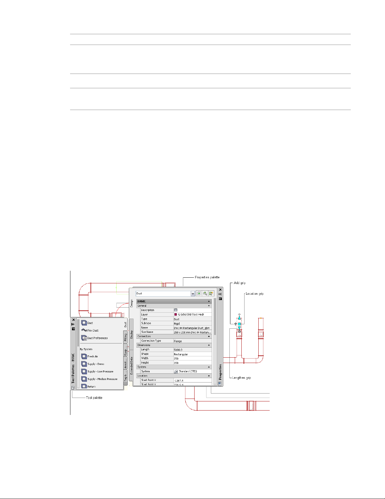
interference detection on page 12, and connectivity checks on page 13 using
domain-specific ribbons and palettes
and display components based on elevation as you lay out the run.
Creating Building Systems
AutoCAD meets the fundamental drafting needs of the AEC, civil engineering, and manufacturing industries.
You use basic geometric elements, such as lines, arcs, and circles, to draw engineering layouts.
With AutoCAD MEP, you create intelligent building systems that exceeds AutoCAD capabilities. You use
MEP parts to create complete, connected systems that contain information you can use to analyze and refine
your designs. For example, you can create a duct system on page 194 that contains ceiling diffusers with a
specified flow rate. The system can detect the amount of downstream airflow required by the diffusers. You
can use sloped piping on page 256 to design gravity-based piping system. You can use circuit features on page
380 to create and manage circuits for your electrical plans. You can place plumbing equipment and fixtures
in a drawing to create a plumbing run on page 464.
In AutoCAD MEPIn AutoCADFunctionality
yesnoAutomate many building system design tasks such as auto layout on page 12,
yesnoCreate accurate construction documents on page 15 with tagging and annotation.
yesnoAutomatically add layout symbols on page 18, such as rise/drop, hidden lines,
AutoCAD MEP Workspaces
Out of the box, AutoCAD MEP contains tools geared to mechanical, electrical, and plumbing professionals
in the building industry. The workspace environments (electrical, HVAC, piping, plumbing, and schematic)
include individual palettes and domain-specific ribbons to optimize your workflow tasks.
Duct system in AutoCAD MEP HVAC workspace
The tool palette includes parts related to the current domain. You can define tool properties from the tool
or properties palette. You can also customize the tool palette to include unique tools commonly used in
6 | Chapter 2 Moving from AutoCAD to AutoCAD MEP
Page 25

your company’s engineering designs. For more information, see Working with Tool Palettes on page 87 and
Customizing Tool Palettes on page 787.
RELATED See also Workspace Components on page 38.
Insertion Tools
You can use add grips ( ) along with the domain-specific palettes in AutoCAD MEP to add components
to your drawings. After adding a part from the tool palette, use add grips on a segment or object to route
the pipe, plumbing, electrical, schematic, or duct system to ensure connectivity along the run. You can draw
a run from one end of the part segment, from a midpoint of a part segment, from a multi-view part (called
an MvPart), or from a fitting, such as an elbow or a tee. For more information, see Grips for Adding to a Pipe
Run on page 272.
AutoCAD MEP also lets you automatically insert fittings into a run. For example, AutoCAD MEP can identify
the type of elbow fitting to insert into a plumbing layout, based on the preferences defined for the plumbing
system. When drawing pipe runs, you can use different routing preferences on page 250 that match your
pipe specifications to ensure that the proper fittings are inserted automatically. As you draw cable tray or
conduit in the Electrical workspace, the software adds fittings based on the defined preferences.
Layer Keying
As you add parts to your layouts, each object is automatically placed on the correct layer. With layer keying,
AutoCAD MEP automatically places an object on a predefined layer that conforms to a particular layer
standard. You can modify the layer standards to map to specific company standards. You can also turn layers
on or off for a particular system or use filters to disable objects on a particular layer. For more information,
see AutoCAD MEP Layer Standards on page 132.
Modifying Building Systems
In AutoCAD, you modify the geometric elements, including lines, arcs, and circles, in your design projects.
You use common editing tools in the software, such as COPY, TRIM, and EXTEND. See the AutoCAD Help
for more information.
AutoCAD MEP helps you streamline the task of modifying building systems using techniques such as
associative movement, grips, and snaps.
Associative Movement
You can move, shrink, or stretch connected objects (such as part segments and fittings) to a new location
in a drawing without breaking the connection between parts or altering other portions of the run. For more
information, see Associative Movement on page 248.
With associative movement, you use grips to move the connected parts as a single unit while other parts
remain in place in the same layout. The software identifies the parts that are connected and maintains their
connectivity. The following illustrations show the progression of the associative movement feature in the
Piping domain.
Insertion Tools | 7
Page 26
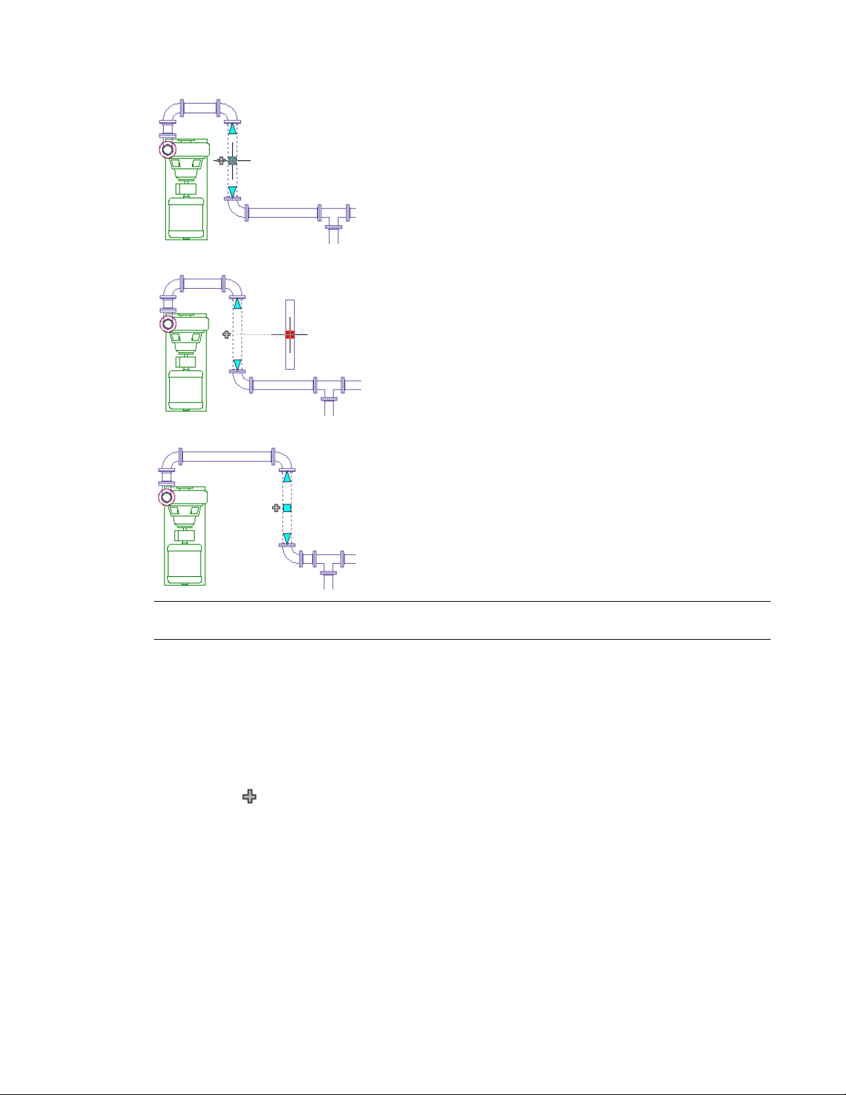
Moving pipe using location grip
Dragging to new location
Resulting layout
Grips
NOTE Associative movement lets you move objects in the XY plane. You can also modify the elevation of connected
parts relative to their top, centerline, or bottom orientation in side and isometric views.
You can use grips to make direct changes to a part segment in a drawing. Hovering over a grip displays a
tooltip describing the grip’s function. Some tooltips also suggest options, such as using the CTRL or ALT
keys. For more information, see Designing with Dynamic Input and Grips on page 114.
Several types of grips are available:
■ Add grips ( ) add segments, such as duct, pipe, plumbing line, wire, cable tray, or conduit, to a new
or existing run without sacrificing connectivity along the run.
8 | Chapter 2 Moving from AutoCAD to AutoCAD MEP
Page 27
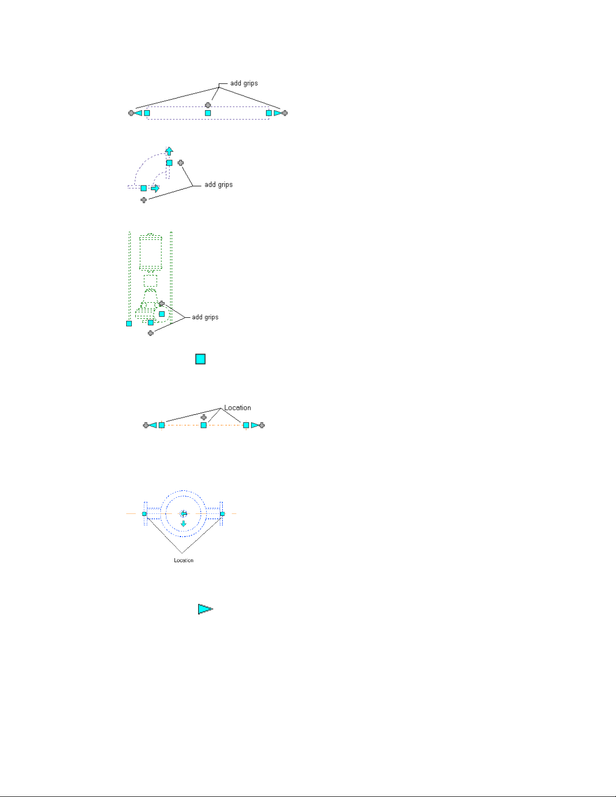
Pipe segment
Pipe fitting (elbow with flange connections)
Base-mounted pump (MvPart)
■ Location grips ( ) move a component in the current XY plane. Location grips appear at the insertion
and connector points on a part.
Plumbing
MvPart
■ Lengthen grips ( ) change the length of a part segment. Lengthen grips use the segment's current
orientation to maintain connectivity in the existing run.
Grips | 9
Page 28
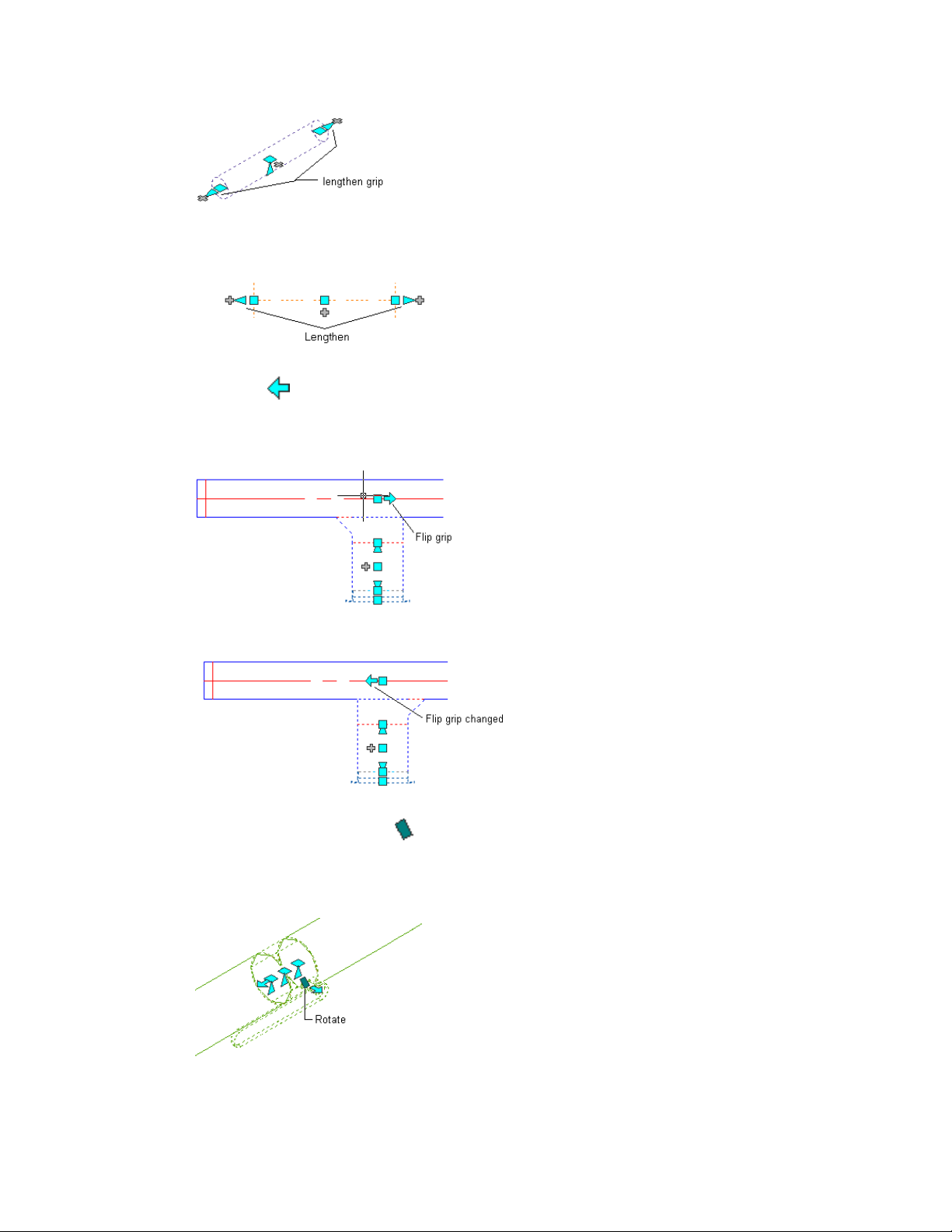
Piping
Plumbing
■ Flip grips ( ) switch the orientation of some parts (such as fittings or takeoffs) based on the direction
of the grip.
Takeoff selected — Flip grip shown
Orientation flipped
■ Diamond-shaped rotate grips ( ) in isometric views rotate an object around its centerline to any angle,
if that object has round connectors on opposite ends. Rotate grips are available on parts and fittings that
can be rotated without breaking the connection with existing objects.
Rotating a damper in an isometric view
10 | Chapter 2 Moving from AutoCAD to AutoCAD MEP
Page 29
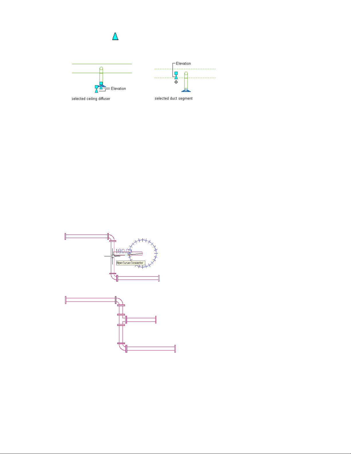
Snaps
■ Elevation grips ( ) modify the elevation of part segments in side and isometric views relative to the
top, centerline, or bottom of the segment. Elevation grips appear at the insertion and connector points
on the specified part segment.
AutoCAD MEP includes AutoCAD object snaps and AutoCAD MEP snaps. You use object snaps to snap
drawing points to geometric locations on other objects. For example, you can snap to the endpoint of a line
or snap to the intersection of 2 lines.
AutoCAD MEP snaps connect MEP objects to other objects, maintaining the integrity and connectivity of
the system. For example, you can use pipe snaps to connect a pipe, fitting, or MvPart directly to a pipe end
connector at the end of a pipe segment. AutoCAD MEP snaps are available in all the engineering workspaces.
For more information, see Configuring AutoCAD MEP Snaps on page 75.
Segments, such as duct and pipe, contain end connector snaps and curve connector snaps. End connector
snaps connect new objects to the ends of existing objects. Curve connector snaps connect a segment anywhere
along the centerlines of existing objects. For example, when you can use pipe curve connector snaps on an
existing pipe run, the software inserts a pipe fitting in the resulting branch, as shown next.
Snapping a pipe to an existing run using the pipe
curve connector
Resulting branch with an inserted fitting
You can use electrical snaps to wire a junction box to a light. You can also use wireway snaps to make
connections to a cable tray, conduit, or electrical MvParts.
Snaps | 11
Page 30
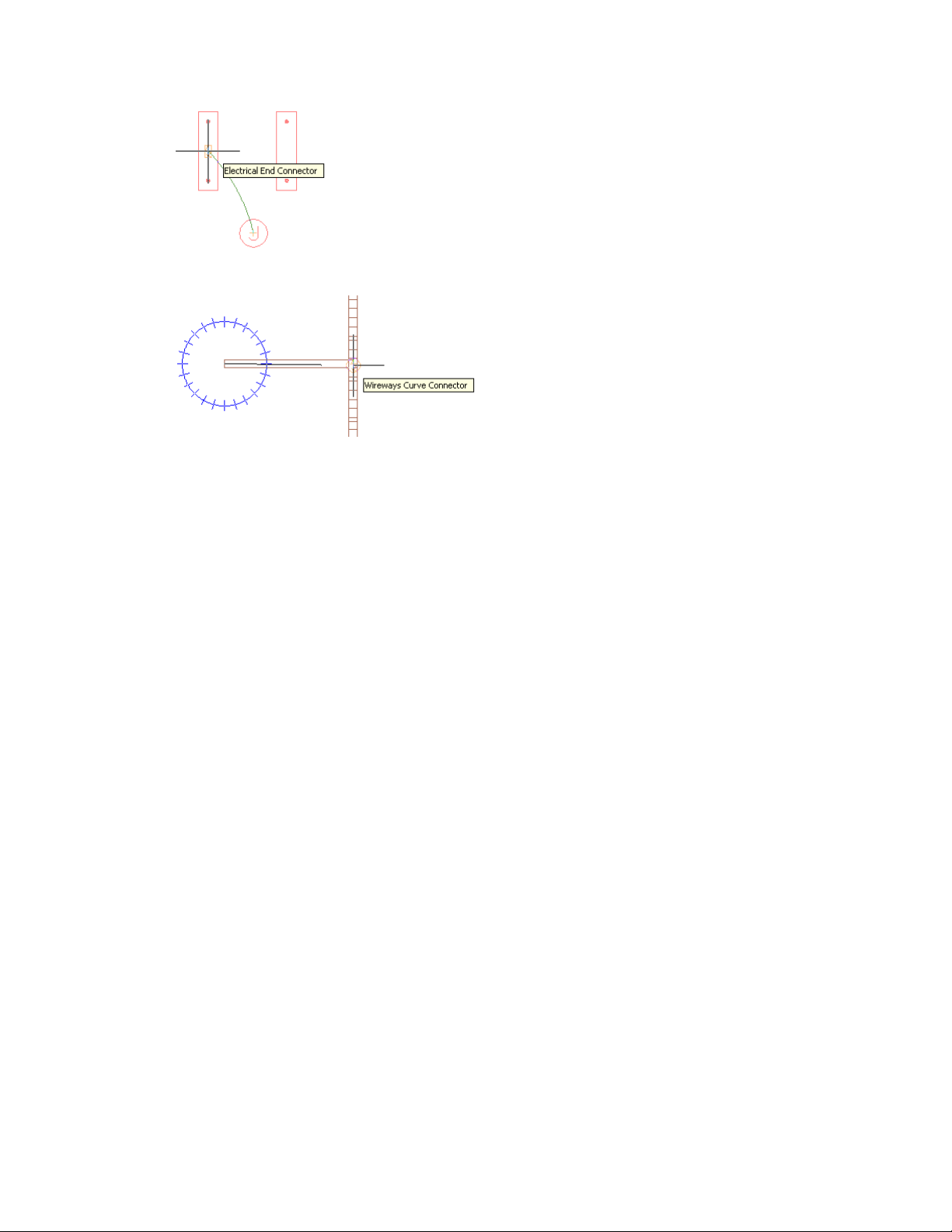
Electrical
Wireways
Automating Design Tasks
In AutoCAD, design tasks are performed manually. AutoCAD does not automatically update the part
specification data in construction documents.
AutoCAD MEP includes features that automate many engineering tasks and provides immediate feedback
as you perform those tasks.
Domain-Specific Ribbons
Out of the box, each engineering workspace in AutoCAD MEP includes a contextual ribbon with preferences
and system definitions unique to the active domain. You can use preferences to automate many design
layout functions. For example, you can define default parts to use during layout, and you can also specify
properties, such as annotation labels, connection behavior, and display settings.
AutoCAD MEP provides system definitions, such as design rules, display properties, and rise/drop
configurations. System definition settings control the appearance and functions of parts in a system. You
can also override system settings to accommodate unique part requirements. For more information, see
Workspace Components on page 38.
Auto Layout
Auto layout can generate routing solutions that you can use as you lay out duct, pipe, cable tray, or conduit
runs. AutoCAD MEP automatically inserts the appropriate segments and fittings based on the current part
or routing preferences. For more information, see Auto Layout on page 252.
Interference Detection
You can improve project coordination using the interference detection tool. The software checks for
interferences between different types of objects, such as between ducts and pipes or between these MEP
objects and architectural/structural objects, such as walls. Interference detection can occur on objects within
the current drawing, objects in referenced drawings (xrefs), or objects in both the current drawing and in
12 | Chapter 2 Moving from AutoCAD to AutoCAD MEP
Page 31

an xref. AutoCAD MEP shows interferences as mass elements in the drawing. You can add tags to the mass
element and insert opening symbols that get captured in a linked interference detection schedule. For more
information, see Finding Interferences on page 582.
Connectivity Checks
The built-in connectivity tools ensure that objects are properly connected and that adjacent objects are
updated accordingly. Connectivity tools also promote the precision of the sizing and calculation tools.
You use the Show Connected Run command to verify the connectivity in a duct, pipe, plumbing line,
conduit, cable tray, or wired electrical run. This functionality is especially useful with complicated designs.
You use the Show Connected Objects command to identify the other objects that are connected to a particular
object. The software verifies that adjacent parts are properly connected and that connectivity is continuous
throughout the run or branches. In the Electrical workspace, the Show Connected Objects command checks
the connectivity between the lighting devices, wires, junction boxes, and switches in a lighting network, as
well as between MvParts and conduit or cable tray runs.
Working With Sizing and Calculation Tools
AutoCAD MEP includes several built-in sizing and calculation tools.
Sizing Tools
Because duct systems connect intelligently, AutoCAD MEP can calculate duct sizes. The software uses the
air flow values you assign for the outlet parts in a duct system. The Duct System Size Calculator computes
duct sizes for an entire connected system or for portions of a system. The Instant Sizing Calculator computes
sizes for ductwork as you draw duct runs or when you modify existing runs.
Instant sizing tool
Connectivity Checks | 13
Page 32

Electrical Circuit Manager
You can configure circuits and panels for electrical systems. When you assign devices to a circuit, the device
loads are automatically added to the circuit load. The Circuit Manager displays circuit load, circuit information,
or a circuit report for one or more selected devices. The Circuit Manager also displays overloaded circuits in
red. You can turn on a feature to be notified when a circuit is overloaded as you are assigning devices to
circuits. For more information, see Checking Electrical Systems on page 425.
Plumbing Tools
Out of the box, AutoCAD MEP includes sample sizing tables for supply lines and sanitary lines, based on
typical industry standards. Supply plumbing line sizing tables specify the equivalent plumbing line length
values for fittings and valves. Sanitary plumbing line sizing tables specify the maximum allowable fixture
unit loads for different types of sanitary runs (stacks, branches, and offsets). You can also customize the
sizing tables to meet your project requirements or conform to applicable codes.
You can also use the plumbing line slope tool to compute the start elevation, end elevation, or slope of a
plumbing line based on the starting or ending points in the run. The software prompts for one of three
entries — starting point of the segment, ending point, or slope. For more information, see Calculating the
Slope of a Plumbing Line on page 495.
Pipe Routing Preferences
AutoCAD MEP uses the routing preference in the Piping domain as specified in the Style Manager to insert
fittings as you draw the pipe run. If you try to add or modify a part, angle, or transition that is not defined
in the current routing preference, AutoCAD MEP prompts you to make a part substitution. You are also
14 | Chapter 2 Moving from AutoCAD to AutoCAD MEP
Page 33

prompted if you try to connect objects with different joint types. For more information, see Routing
Preferences on page 250 and Choosing a Part on page 303.
Solution Tips
AutoCAD MEP displays optional solution tips that highlight where invalid connections exist between objects
in the layout. Solution tips describe the problem and offer one or more possible solutions. For more
information, see Showing Solution Tips on page 579.
Creating Accurate Construction Documents
In AutoCAD, there is no automated way to revise construction documents to reflect changes in your original
drawing or to automate the creation of section views. As the design changes, manually updating section
views is not only time-consuming but also error-prone. You also would need to use a text editor in AutoCAD
to perform tasks, such as adding labels to objects, formatting text, justifying positioning, or setting scale
representations.
In AutoCAD MEP, you can maximize your productivity using automated tools, such as tagging, labeling,
annotation scaling, and layout symbols. Because project drawings are created, stored, and maintained using
the drawing management tools in AutoCAD MEP, the resulting construction documents are updated
automatically when changes get made.
Section Views
You can create section views from your AutoCAD MEP model, as shown next.
Solution Tips | 15
Page 34

Specifies the parts of the drawing to include in the new
section view
Tagging
You can regenerate section views after you change any aspects of the model. Because you view AutoCAD
MEP systems in 3 dimensions, you can also create elevation and detail views. For more information, see
Creating a Section View on page 570.
AutoCAD MEP automates part tagging. For example, as you create a building system, you can add part
number tags to objects in the drawing.
16 | Chapter 2 Moving from AutoCAD to AutoCAD MEP
Page 35

Property set data for a ceiling diffuser
Each tagged part contains a property set that you configure on the Properties palette based on the part
specification. Part schedules linked to the drawing reflect the tagged data. For more information, see Defining
Property Set Data on page 588 and Tags on page 561.
Labeling and Annotation Scaling
AutoCAD MEP lets you add labels and flow arrows as you lay out a run. You can specify the number of labels
or flow arrows and the placement of the annotation. As you make changes, the labeling updates automatically.
Labeling and Annotation Scaling | 17
Page 36

The annotation scaling feature lets you specify different annotation scales for model space and for individual
viewports in paper space. The annotation scales and plots accurately even if different scales for the viewports
in the layout are used.
Layout Symbols
AutoCAD MEP displays symbols that represent unique conditions in the layout. For example, rise/drop
symbols reflects the elevation direction of vertical segments in the layout for any predefined orthographic
view (top, bottom, left, right, front, or back).
You can display objects differently based on elevation on page 144. You can also change the appearance of
hidden lines, layers, line types, or color for crossing or overlapping objects at different elevations in 2-line
plan views. For example, AutoCAD MEP displays hidden lines as dashes, as shown next. For more information
about the various display options in AutoCAD MEP, see AutoCAD MEP Displays on page 134.
Hidden lines shown as dashes
18 | Chapter 2 Moving from AutoCAD to AutoCAD MEP
Page 37

Project Management
AutoCAD MEP controls the management of project sheets and views through the use of the Project Navigator.
As you design systems in AutoCAD MEP, you develop 3-dimensional models that are saved in construct
drawings.
Construction documents consist of views and sheets. A view references the model in the construct drawing,
and it consists of one view of the model with a specific drawing scale. Two examples of view drawings are
a cross-sectional view of an HVAC system and a floor plan of a lighting system.
Views are referenced onto sheets for plotting or transmitting. Because views and sheets reference the model,
you only need to update the model, and the changes are automatically propagated through the views and
sheets.
Schedules
Creating and maintaining accurate schedules can be complex, error-prone, and time-consuming. However,
AutoCAD MEP automates this task by linking the schedule to the original AutoCAD MEP designs.
An MEP schedule displays tagged parts, along with selected attributes for each part, in tabular form, as shown
next.
Device schedule
Because schedules built in AutoCAD MEP are linked, any changes, additions, or deletions to the existing
tagging data or part specifications are automatically updated in the schedule. The schedule format inherits
the schedule table style assigned to the schedule tool. However, you can modify the table style to reflect the
desired data format.
Leveraging AutoCAD Knowledge in AutoCAD MEP
The AutoCAD user interface guides you through the CAD design process. AutoCAD MEP builds on the
fundamental infrastructure, capabilities, and familiar AutoCAD user interface. Therefore, you do not need
to toss away your knowledge about AutoCAD.
Your familiarity with AutoCAD helps you lessen your learning curve and maximize your productivity. The
contextual ribbon structures, domain-specific tool and properties palettes, and task-oriented dialogs in
AutoCAD MEP reflect the particular task-based design work you are performing. For more information, see
Workspace Components on page 38.
The AutoCAD command line is also available at the lower left corner of the AutoCAD MEP user interface.
When you enter a command, the software prompts you with the next step. For more information about the
command line, see the AutoCAD Help.
Command line
Project Management | 19
Page 38

Working with AutoCAD Commands in AutoCAD MEP
Because AutoCAD MEP is built on the AutoCAD infrastructure, all of the commands in AutoCAD are available
in AutoCAD MEP. However, some differences exist between the commands to modify basic AutoCAD objects,
such as lines, polylines, and arcs, and the commands to modify intelligent building systems objects, such
as parts, fittings, and segments of duct, pipe, or cable tray.
This section provides guidance on using AutoCAD commands in an AutoCAD MEP environment. The effects
of commands on building systems objects are discussed, and, where applicable, alternative or more enhanced
methods of accomplishing tasks are suggested.
NOTE Many of the sections that follow reference AutoCAD Help topics. The quickest way to locate an AutoCAD
topic referenced in AutoCAD MEP Help is to click the Search tab in the Help window, select the Search titles only
option, copy and paste or enter the AutoCAD topic name, and then click List Topics.
ALIGN
The ALIGN command moves, rotates, and tilts objects so they align with other objects.
When you use ALIGN to align an object in AutoCAD MEP, you can snap and attach the object to another
at the new location, but the command does not intelligently connect the 2 objects. This action results in
an invalid connection in the overall building system.
To maintain the connectivity of objects, use Alignment grips to align devices or panels, and use Location
or Rotate grips, snaps, and polar tracking to align other objects. The grips enable you to move or rotate
objects while optionally maintaining their connections to other objects.
ARRAY
For more information, see the following topics:
■ Moving Duct Components on page 221
■ Rotating Duct Components on page 228
■ Moving Pipe Components Using Location Grips on page 320
■ Rotating Pipe Components on page 321
■ Moving a Device or Panel on page 431
■ Modifying the Layout of a Cable Tray or Conduit Run on page 444
■ Rotating Cable Tray or Conduit Fittings on page 450
■ Moving Plumbing Lines and Fittings on page 497
■ Rotating Plumbing Fittings on page 498
■ “Align Objects” in the AutoCAD Help
The ARRAY command creates copies of objects in a rectangular or polar (circular) pattern called an array.
In AutoCAD MEP, you can use ARRAY to create arrays of a selection set of objects (for example, a complete
duct branch). If possible, the software connects a suitable object in each copy of the selection set, such as a
tee or takeoff, to a segment at each destination.
Unlike COPY or MOVE, ARRAY does not align or orient the copies of the selection set when it connects
them to objects at their destinations. The copies maintain the alignment and orientation of the original
selection set.
20 | Chapter 2 Moving from AutoCAD to AutoCAD MEP
Page 39

For more information, see “Create an Array of Objects” in the AutoCAD Help.
BREAK
The BREAK command breaks an object between 2 points that you specify and optionally creates a gap
between the new objects that are created.
In AutoCAD MEP, when you use BREAK to break segments of duct, pipe, cable tray, or conduit, or to break
plumbing lines, the software connects the 2 new segments if the first and second specified break points are
the same. However, when you break a segment where a takeoff is connected, the software connects the
takeoff to only 1 of the 2 new segments. You should reposition the takeoff as needed.
You can break one or more duct, pipe, cable tray, or conduit segments into multiple segments of a specific
length. For example, in the Piping domain, you use the Pipe Length on page 329 dialog.
For more information about BREAK, see “Break and Join Objects” in the AutoCAD Help. For more information
about breaking segments into multiple segments in AutoCAD MEP, see:
■ Breaking or Merging Duct on page 234
■ Breaking or Merging Pipe Segments on page 329
■ Breaking and Merging Cable Tray or Conduit Segments on page 449
CHAMFER
COPY
ERASE
The CHAMFER command connects 2 objects with an angled line. It is typically used to represent a beveled
edge on a corner, but it can also be used to extend 2 objects until they intersect.
In AutoCAD MEP, CHAMFER only works on AutoCAD objects, such as lines, polylines, and 3D solids. It
does not work on building systems objects, such as schematic lines, plumbing lines, or duct, pipe, cable tray,
or conduit segments. To extend and connect these types of objects, use FILLET, EXTEND, or a combination
of grips, snaps, and polar tracking.
For more information, see “Create Chamfers” in the AutoCAD Help.
The COPY command creates duplicates of objects at a specified distance and direction from the originals.
In AutoCAD MEP, when you use COPY to copy a selection set of objects (for example, a complete duct
branch), the software copies the objects and, if possible, connects a suitable object in the selection set, such
as a tee or takeoff, to a segment at the destination. When connecting the object, the software breaks into
the segment and then aligns and orientates the object (and the selection set). For more information, see
“Copy Objects” in the AutoCAD Help.
To copy a device or panel, use Alignment grips instead. The grips enable you to align the copy perpendicular
to an object, such as a wall. For more information, see Copying Devices and Panels on page 409.
The ERASE command removes a selection set of objects from a drawing.
In some cases in AutoCAD MEP, ERASE joins the objects that remain after you erase an object. For example,
it joins remaining duct or pipe segments when you erase inline parts. However, when you erase fittings, the
BREAK | 21
Page 40

software disconnects the remaining objects because it does not know how to join them. In these cases, you
can connect or merge the disconnected objects to reflect the desired design.
NOTE Erasing objects does not remove unused, named items from a drawing. You must purge them.
For more information, see the following topics:
■ Breaking and Merging Duct Segments on page 234
■ Breaking or Merging Pipe Segments on page 329
■ Breaking and Merging Cable Tray or Conduit Segments on page 449
■ “Erase Objects” in the AutoCAD Help
EXPLODE
The EXPLODE command breaks a compound object into its component objects.
In AutoCAD MEP, the first time that you explode a building systems object (for example, a part or fitting),
the software converts the object to an anonymous block reference and changes its Z (elevation) value to
zero. You can then explode the object again to convert it to its primitive AutoCAD components, such as
lines, arcs, and splines.
Typically, you explode the objects in a drawing in order to share the drawing with users who do not have
AutoCAD MEP or an AutoCAD MEP object enabler, or who have a version of AutoCAD not supported by
the Export to AutoCAD commands.
EXTEND
FILLET
WARNING Exploding a building systems object causes the object to permanently lose its connectivity with other
objects, among other changes. For this reason, always create a copy of the source drawing, and then explode the
objects on the copy.
For more information, see Export to AutoCAD on page 591.
The EXTEND command extends objects to meet other objects.
In AutoCAD MEP, EXTEND works on duct, pipe, cable tray, and conduit segments, and plumbing lines.
However, fittings are not automatically inserted. To have fittings inserted automatically based on the
preferences in the drawing, use Add grips instead.
You can also extend plumbing lines and schematic lines using the FILLET command.
For more information, see the following topics:
■ Adding Duct Using Grips on page 200
■ Adding Pipe Using Grips on page 302
■ Drawing a Plumbing Run Using Add Grips on page 487
The FILLET command fillets and rounds the corners of objects. If you use this command to connect 2 objects
and set the fillet radius to zero, the command trims or extends the objects until they intersect but does not
create an arc.
22 | Chapter 2 Moving from AutoCAD to AutoCAD MEP
Page 41

In AutoCAD MEP, you can use FILLET to fillet not only AutoCAD objects, such as lines, polylines, and arcs,
but also schematic lines and plumbing lines. By using FILLET with a fillet radius of zero (default), you can
easily connect schematic lines or plumbing lines by extending or trimming them. You can use the command
in orthographic mode or isometric mode.
Filleting plumbing lines
NOTE The resulting single schematic line or plumbing line has the properties of the segment that you select first,
such as system, style, and flow direction. In the case of plumbing lines, the resulting plumbing line also has an
elbow of the type specified for the plumbing system. For more information, see Specifying the Default Fittings for
a Plumbing System Definition on page 478.
For more information about the FILLET or EXTEND commands, see the AutoCAD Help.
JOIN
The JOIN command joins similar objects to form a single, unbroken object. You can also use it to create
complete circles and ellipses from arcs and elliptical arcs.
In AutoCAD MEP, JOIN only works on AutoCAD objects, such as lines, polylines, arcs, and splines. However,
you can join duct, pipe, cable tray, or conduit segments, as well as plumbing lines, by merging them. You
can also connect plumbing lines or schematic lines with the FILLET command.
For more information, see the following topics:
■ Breaking or Merging Duct on page 234
■ Breaking or Merging Pipe Segments on page 329
■ Breaking and Merging Cable Tray or Conduit Segments on page 449
LENGTHEN
The LENGTHEN command changes the length of lines, polylines, arcs, and splines and the included angle
of arcs.
In AutoCAD MEP, LENGTHEN does not work on duct, pipe, cable tray, or conduit segments. Rather, you
can use Lengthen grips to modify the length of segments. Depending on the editing mode you select, the
grips move or lengthen connected objects to maintain their connectivity.
JOIN | 23
Page 42

For more information, see the following topics:
■ Modifying the Length of Ducts on page 225
■ Modifying the Length of a Pipe Segment on page 322
■ Modifying the Length of Cable Tray or Conduit Segments on page 446
■ Modifying the Length of Plumbing Lines on page 497
■ “Resize or Reshape Objects” in the AutoCAD Help
MATCHPROP
The MATCHPROP command copies some or all of the properties of one object to other objects.
In AutoCAD MEP, MATCHPROP only copies AutoCAD object properties, such as color, layer, linetype, and
lineweight. To copy building systems object properties, such as system, elevation, and size, use the Match
command option when adding or modifying an object. For more information see the following topics:
■ Using Object Match on page 826
■ “Copy Properties Between Objects” in the AutoCAD Help
MIRROR
MOVE
In AutoCAD, the MIRROR command creates a mirror image copy of an object. MIRROR works similarly in
AutoCAD MEP. For more information, see “Mirror Objects” in the AutoCAD Help.
The MOVE command moves objects a specified distance in a specified direction.
In AutoCAD MEP, when you use MOVE to move a selection set of parts, fittings, and segments (for example,
a complete duct branch), the software moves the objects and, if possible, connects a suitable object in the
selection set, such as a tee or takeoff, to a segment at the destination. When connecting the moved object
to the segment, the software breaks into the segment and then aligns and orients the object (and the selection
set). However, the command does not connect or adjust disconnected objects that remain at the original
location.
As an alternative to MOVE, use Location grips to move parts, fittings, segments, and schematic symbols.
Depending on the editing mode you select, the Location grips move or adjust all affected objects to maintain
the connectivity of the run.
To move devices or panels, use Alignment grips. The grips let you accurately align a device or panel
perpendicular to an object, such as a wall.
To move schematic lines, use MOVE or enter a new location on the Location tab of the Schematic Line
Properties dialog.
For more information, see the following topics:
■ Moving Duct Components on page 221
■ Moving Pipe Components Using Location Grips on page 320
■ Moving a Device or Panel on page 431
■ Modifying the Layout of a Cable Tray or Conduit Run on page 444
24 | Chapter 2 Moving from AutoCAD to AutoCAD MEP
Page 43

OFFSET
PURGE
■ Moving Plumbing Lines and Fittings on page 497
■ Rotating Isometric Symbols on page 542
■ Moving Schematic Lines on page 538
■ “Move Objects” in the AutoCAD Help
The OFFSET command copies a selected object, giving the copy a shape that reflects the original. Because
OFFSET offsets polylines, in AutoCAD MEP you can use it to offset schematic lines.
You can also use this command to offset individual segments of duct, pipe, cable tray, or conduit, and
individual plumbing lines. However, because the command does not support the selection of multiple
objects, you cannot use it to offset a complete run.
For more information, see “Offset an Object” in the AutoCAD Help.
The PURGE command removes unused, named AutoCAD objects, such as blocks, layers, and styles, from a
drawing.
Because PURGE purges only AutoCAD objects, in AutoCAD MEP you should purge unused building systems
objects first, and then use the Style Manager to purge unused system definitions.
For more information, see the following topics:
■ Purging AutoCAD MEP Objects on page 590
■ Purging Systems on page 101
■ “Erase Objects” in the AutoCAD Help
ROTATE and ROTATE3D
The ROTATE command rotates an object around a base point. The ROTATE3D command rotates an object
around a 3-dimensional axis.
In AutoCAD MEP, you can use ROTATE3D to rotate fittings around a specified axis and connection point.
However, a quicker and easier alternative is Rotate grips. In plan or isometric views, you can use Rotate grips
to rotate both fittings and inline parts. The grips adjust connected objects and maintain their connectivity
whenever possible.
For more information, see the following topics:
■ Rotating Duct Components on page 228
■ Rotating Pipe Components on page 321
■ Rotating Cable Tray or Conduit Fittings on page 450
■ Rotating Plumbing Fittings on page 498
■ “Rotate Objects” in the AutoCAD Help
OFFSET | 25
Page 44

SCALE
The SCALE command makes an object uniformly larger or smaller.
In AutoCAD MEP, SCALE properly resizes schematic symbols, electrical devices, electrical panels, plumbing
fittings, and plumbing valves. You can also resize schematic symbols using their grips in Scale grip mode.
For more information, see the following topics:
■ Resizing Schematic Symbols on page 544
■ “Resize or Reshape Objects” in the AutoCAD Help
STRETCH
The STRETCH command relocates the object endpoints that lie across or within a crossing window selection.
In AutoCAD MEP, STRETCH increases the length of ducts, pipes, cable trays, conduits, and plumbing lines,
but it does not adjust connected objects and can break their connectivity. For this reason, use Lengthen
grips, instead of STRETCH, to modify the lengths of segments. Depending on the editing mode you select,
the Lengthen grips move or lengthen connected objects to maintain their connectivity. On unconnected
segments, you can also use the Start or End grips to change both the length and angle of the segment. To
stretch or change the angle of a schematic line, drag a grip point to a new location.
For more information, see the following topics:
■ Modifying the Length of Ducts on page 225
■ Modifying the Length of a Pipe Segment on page 322
■ Modifying the Length of Cable Tray or Conduit Segments on page 446
■ Modifying the Length of Plumbing Lines on page 497
■ Modifying the Length of Schematic Lines on page 541
■ “Resize or Reshape Objects” in the AutoCAD Help
TRIM
The TRIM command trims objects at a cutting edge defined by other objects.
In AutoCAD MEP, TRIM only works on plumbing lines and segments of duct, pipe, cable tray, and conduit.
However, fittings are not automatically inserted. For more information, see “Trim or Extend Objects” in the
AutoCAD Help.
Help Resources
The AutoCAD MEP Help provides various help resources. Click and then click a help resources in the
list. You can also explore various help resources in the Welcome Screen page in AutoCAD MEP.
26 | Chapter 2 Moving from AutoCAD to AutoCAD MEP
Page 45

Getting Started
3
Welcome to AutoCAD MEP 2010, an AutoCAD-based building design and construction documentation solution for
Mechanical/Electrical/Plumbing engineers, designers, and drafters.
This section introduces you to the software and describes how to contact Autodesk, get help, navigate the user interface,
and perform basic but important tasks.
About AutoCAD MEP
AutoCAD MEP is designed for the MEP (mechanical, electrical, piping, and plumbing) disciplines in the
building industry. It includes:
■ Catalogs of drawing objects that represent the real-world parts in building systems and that connect
intelligently to one another.
■ Tools specific to the mechanical, electrical, and plumbing disciplines, such as analysis tools for sizing
systems for optimal performance.
■ Common design tools that you can use in all 3 disciplines:
■ Project management tools that integrate building system designs with architectural building plans.
■ Tools for specifying design preferences that control how objects appear and behave.
■ Drawing templates with basic, standards-based settings to get you started quickly.
You can use the software to design comprehensive systems for commercial, institutional, and residential
building plans.
27
Page 46

AutoCAD MEP Workflow
AutoCAD MEP provides features that allow the creation of very complex designs. While the software has
many intricacies, there is a basic workflow for using it. Use the following table to navigate to detailed
workflows for designing mechanical, electrical, and plumbing systems.
Establish high-level project
parameters, and create document
sets
View more informationGeneral task
Define project standards, the look of the drawing
area, the look of parts, the tool catalogs to use,
and other settings. See Working with Drawing
-----
Management Projects on page 129. Create sheets,
sheet lists, and cover sheets for construction
document sets. See Construction Document
Workflow on page 547.
Use Project Navigator to create cross references
to the floor plans onto to which MEP designs will
-----Link to architectural floor plans
display. See Working with Referenced Drawings
on page 158
Create preliminary domain outlines
using flow and 1-line diagrams
Create detailed domain designs
using catalog parts and custom
content
Intelligent Objects
Use the schematic tool set in MEP to create
-----
concept designs. See About Schematic Diagrams
on page 518
Create:
■ HVAC designs on page 163
■ Electrical designs
-----
■ Plumbing designs
■ Radiant heating system designs
■ Piping system designs
Use Drawing Compare to see how drawings differ
-----Circulate designs for review
from one revision to another. See Comparing
Drawings on page 592
AutoCAD MEP is an object-based CAD application. When you design in the application, you use large
collections of objects that represent the real-world components in mechanical, electrical, and plumbing
systems. Examples of these objects include segments of duct, pipe, cable tray, and plumbing lines; fittings
of all types; and equipment—called multi-view parts or MvParts in the software—such as air handling units,
electrical transformers, and drinking fountains.
28 | Chapter 3 Getting Started
Page 47

AutoCAD MEP objects are composed of lines, arcs and other standard AutoCAD objects, but they also contain
information that allows them to function like the real-world components that they represent, to relate
intelligently to one another, and to display in a 2-dimensional (2D) or 3-dimensional (3D) context. The
objects have specially designed connection points called connectors that enable them to connect intelligently
to appropriate objects and transfer information, such as shape, size, and system.
As an example, you can insert a variable air volume (VAV) box into an HVAC system drawing, and then
draw a duct from one of its connectors. When you draw the duct, the software detects the size and shape
of the connector on the VAV box and draws an appropriate duct segment as shown.
Drawing duct from a VAV box
To continue the example, you can draw and connect additional duct segments, fittings, and HVAC equipment
that are all intelligently connected in the same manner. As you do so, the software inserts and adjusts the
objects in the run to maintain their connectivity. For example, it inserts appropriately-sized fittings as you
lay out duct segments. It also inserts an appropriately-sized transition fitting if you change the size of a
segment.
The ability of the software to detect the attributes of objects and act accordingly to maintain the connectivity
of the system is an important aspect of the software. It enables you to design fully connected systems quickly
and preserves their connectivity when you modify them.
Location of Part Catalogs
AutoCAD MEP includes objects that include hundreds of industry-specific, standards-based fittings and
multi-view parts called MvParts. The objects are organized into part catalogs, which you access when you
add or modify objects in your drawings.
The following part catalogs are available in both imperial and metric units:
■ Cable Tray
■ Conduit
■ Duct
■ MvParts on page 76 for all building systems disciplines
■ Pipe
The software also includes additional content for style-based objects: electrical devices and panels, plumbing
fittings and valves, and schematic symbols.
Location of Part Catalogs | 29
Page 48

For more information on part catalogs, see Working with Catalog-Based Content on page 79.
Analysis Tools
Mechanical, electrical, and plumbing systems require analysis to ensure proper sizing and operation. AutoCAD
MEP includes several, integrated engineering tools for performing analyses:
■ Before you begin to design, you can model spaces and zones to determine the heating and cooling loads
for a building plan. You can also export the engineering data in Green Building Extensible Markup
Language (gbXML) for analysis by third-party tools, and then import the results into your drawing. For
more information, see Calculating Duct Sizes Using External Tools on page 241.
■ As you draw, you can use instant sizing tools to calculate duct or wire sizes. For more information, see
Drawing a Duct Run on page 196 or Drawing or Generating Wires on page 413.
■ After you complete your design, you can analyze the HVAC, electrical, or plumbing system to check
loads and resize components for optimal performance. For more information, see Calculating Duct Sizes
for a Duct System on page 203, Calculating Wire Sizes Using the Circuit Manager on page 425, Calculating
the Sizes of Supply Plumbing Lines on page 501, or Calculating the Sizes of Sanitary Plumbing Lines on
page 508.
Project Management Tools
AutoCAD MEP includes tools that formalize and automate the processes related to building model design
and documentation:
■ a Project Browser—Use this tool to create design projects and specify high-level project information and
settings, such as the project number, project name, and the file locations of the tool palettes and content
library to use on the project.
■ a Project Navigator—Use this tool to perform project-specific tasks, such as defining building levels and
divisions, creating drawings, and creating plotting sheets.
When you manage your project using the Project Browser and Project Navigator, you have consistency in
all aspects of the project. Everyone on your design team has a centralized project environment from which
to access the most current information, tools, and documents—from project templates to composite views
and construction documents.
For more information, see Working with Drawing Management Projects on page 129.
Contacting Autodesk
Use the following resources to contact Autodesk about AutoCAD MEP and other Autodesk products.
Corporate Headquarters
For general inquiries and information, contact Autodesk corporate headquarters:
Autodesk, Inc.
111 McInnis Parkway
San Rafael, CA 94903
USA
Phone: 415-507-5000, Web site: http://www.autodesk.com
30 | Chapter 3 Getting Started
Page 49

Sales Information
To purchase additional Autodesk software, contact your local reseller. For the name of the authorized reseller
nearest you, call 1-800-964-6432 or refer to the Reseller Center Web site: http://www.autodesk.com/resellers.
Technical Support
If you have a technical question, contact your local reseller or refer to the AutoCAD MEP Web site:
http://www.autodesk.com/support. The Web site provides links to frequently asked questions, a searchable
knowledge base, and searchable discussion groups.
For information on other help resources, see Getting Help on page 31.
Feedback
If you have a suggestion for a product enhancement, a compliment, or a complaint, or if you think you
have found a defect, we would like to know about it. To provide feedback, visit the AutoCAD MEP Web site:
http://www.autodesk.com/contact.
Getting Help
AutoCAD MEP includes several resources designed to help you learn the software.
Guides
To quickly get you started with AutoCAD MEP, the software includes several AutoCAD MEP guides in PDF
format:
■ AutoCAD MEP 2010 User’s Guide. This guide includes conceptual information on all features and step-by-step
instructions on performing end user tasks. The information in the guide is also included in the online
help.
■ AutoCAD MEP 2010 Network Administrator’s Guide. This guide provides information on how to perform
network installations or multi-seat, stand-alone installations.
■ AutoCAD MEP 2010 Stand-Alone Installation Guide. This guide provides information on how to perform a
stand-alone installation for an individual user.
You can access PDF versions of the installation guides from the Installation Wizard, which launches when
you insert the installation disc into your DVD drive. Click the Documentation link at the bottom of the left
pane.
A PDF version of the AutoCAD MEP 2010 User’s Guide is located in the following folder: \Program Files\AutoCAD
MEP 2010\Help.
To open or print a guide, you must have Adobe® Acrobat® Reader installed on your computer. If you do not
have Acrobat Reader installed, you can download the latest version from the Adobe Web site:
http://www.adobe.com.
NOTE PDF versions of the user’s guides for AutoCAD Architecture and AutoCAD are also available on the AutoCAD
MEP installation disc. To access them, use Windows® Explorer to navigate to the \Install\docs folder.
Getting Help | 31
Page 50

Tutorials
Training
AutoCAD MEP includes these in-depth, domain-specific tutorials that are available by download:
■ Mechanical/Piping
■ Electrical
■ Plumbing
■ Construction Documents
In addition to these in-depth tutorials, the Express Workshop provides mini-tutorials to get up and running
quickly.
For more information, click ➤ Tutorials from the InfoCenter in the software.
Training programs and products from Autodesk help you learn the key technical features of your Autodesk
software and improve your productivity. For the latest information about Autodesk training, visit
http://www.autodesk.com/autocadmep-training or contact your local Autodesk office.
Classes
Be more productive with Autodesk® software. Get trained at an Autodesk Authorized Training Center (ATC®)
with hands-on, instructor-led classes to help you get the most from your Autodesk products. Enhance your
productivity with proven training from over 1,400 ATC sites in more than 75 countries. For more information
about Autodesk Authorized Training Centers, contact atc.program@autodesk.com or visit the online ATC
locator at http://www.autodesk.com/atc.
Courseware
Autodesk publishes many courseware titles each year for users at all levels to improve their productivity with
Autodesk software. The preferred training materials of Autodesk partners, these books are also well-suited
for self-paced, standalone learning. All courseware simulates real-world projects with hands-on, job-related
exercises. Autodesk Official Training Courseware (AOTC) is developed by Autodesk. Autodesk Authorized
Training Courseware (AATC) is developed by Autodesk partners, including titles in a growing number of
languages. Autodesk Official Certification Courseware (AOCC) teaches the knowledge and skills assessed on
the Certification examinations. Visit http://www.autodesk.com/aotc to browse the Autodesk Courseware catalog.
E-Learning
Autodesk e-Learning for Autodesk Subscription customers features interactive lessons organized into product
catalogs. Each lesson is 20-40 minutes in length and features hands-on exercises, with an option to use a
simulation or the software application. You can also use an online evaluation tool that identifies gaps in
skills, determines what lessons will be most helpful, and gauges learning progress.
If you are a member of Autodesk subscription, you can access e-Learning and other subscription services
from within your Autodesk product. For more information about Autodesk subscription resources, visit
http://www.autodesk.com/subscription.
32 | Chapter 3 Getting Started
Page 51

Certification
Gain a competitive edge with your career by obtaining Autodesk Certification, validating your knowledge
and skills on Autodesk products. Autodesk provides an end-to-end solution for assessing your readiness for
certification, preparing for certification, and obtaining certification. For more information on Autodesk
Certification, visit http://www.autodesk.com/certification.
Discussion Groups
Autodesk provides searchable, peer-to-peer discussion groups and blogs in which you can ask questions and
share information with other users of Autodesk products, including AutoCAD MEP. For more information,
see the Autodesk Web site: http://www.autodesk.com/autocadmep-community.
Additional Resources
From the Help menu in the software, you can access additional help resources, including but not limited to
a searchable AutoCAD MEP knowledge base, resources for developers, and support services for members of
the Autodesk Subscription program.
Updating AutoCAD MEP
AutoCAD MEP includes a notification tool called the Communication Center that keeps you informed about
service pack availability. If you are a member of the Autodesk Subscription program, the Communication
Center also notifies you of additional product information, such as extension availability, tips, and support
information. You can set the Communication Center to notify you of updates and other information daily,
weekly, or monthly, or you can update on demand. For more information, see “Overview of Communication
Center” in the AutoCAD Help.
The AutoCAD MEP 2010 Drawing Domain
The AutoCAD MEP 2010 user interface provides access to the commands and controls that enable the
production of intricate M/E/P designs. Later sections describe this workspace in detail. By way of introduction,
here are the highlights:
Ribbon
Using the Microsoft Office 2007 model, AutoCAD MEP 2010 now uses the ribbon as the central access point
for commands. The ribbon contains a number of tabs on which commands are grouped according to
conceptual task types or selected objects.
The ribbon replaces the menu bar and the toolbars as the primary command access point.
Application Menu
The application menu contains basic commands pertaining to the drawing as a whole: Open, Save, Print,
Export etc. Like the menu browser it replaces, the application menu is accessed by clicking in the
upper-left corner of the workspace.
Discussion Groups | 33
Page 52

Workspaces
AutoCAD MEP is equipped with six workspaces (HVAC, Piping, Electrical, Plumbing, Schematic, and
Architecture). The default workspace after initial installation is HVAC, but can be user-defined (see Workspace
Settings on page 37).
NOTE The tool palette groups associated with all the workspaces are available from the context menu of the tool
palettes set.
Drawing Status Bar Menu
The drawing status bar menu has been removed from AutoCAD MEP 2010. Commands formerly found there
can now be accessed from the application menu.
Commands on the old menu
Help Access
With the removal of the menu bars, the commands to access Help features have been moved into the
InfoCenter at the top right of the application window. Here, you can find the online resources of InfoCenter
and the Help menu, which lets you access Help, Tutorials, and other interactive resources.
34 | Chapter 3 Getting Started
Page 53

Toolbars
Toolbars have been removed from AutoCAD MEP. Commands formerly found on toolbars can now be
accessed from the ribbon.
Autodesk Seek
You can use Autodesk Seek to find product design information. Many content providers, both corporate
partners and individual contributors, publish to Autodesk Seek. Content includes 3D models, 2D drawings,
specifications, brochures, and other descriptions of products or components.
Import design content into AutoCAD MEP 2010
You can also share your own content with others using Autodesk Seek. Upload drawings or blocks to Autodesk
Seek to give your partners and customers ready access to your content.
Workspace Fundamentals
Workspaces are user interface configurations that determine the ribbon panels that display in the drawing
window. For example, the workspace determines whether the Tool Palettes window and Command Line
window float or dock to specific sides of the application window.
If you work in a multi-disciplinary firm and perform several different design tasks, such as the design of
HVAC and piping systems, workspaces are particularly useful. You can use them to save user interface
configurations that are tailored to different tasks. Once the workspaces are created, you can quickly switch
between them as needed.
Workspace Fundamentals | 35
Page 54

Example of Piping workspace
Default Workspaces in AutoCAD MEP
AutoCAD MEP includes pre-built workspaces for several building systems disciplines.
DescriptionWorkspace
HVAC
Piping
Electrical
Plumbing
Schematic
Architecture
Configured for the design of HVAC systems. Ribbon tabs are populated with HVAC tools
and commands, and the HVAC tool palette group is displayed.
Configured for the design of piping systems. Ribbon tabs are populated with piping
tools and commands, and the Piping tool palette group is displayed.
Configured for the design of electrical systems. Ribbon tabs are populated with electrical
tools and commands, and the electrical Electrical tool palette is displayed.
Configured for the design of plumbing systems. Ribbon tabs are populated with
plumbing tools and commands, and the Plumbing tool palette group is displayed.
Configured for the design of schematic diagrams. Ribbon tabs are populated with
schematic tools and commands, and the Schematic tool palette is displayed.
Configured for the design of architectural plans. Ribbon tabs are populated with architecture-specific tools and commands and the architecture tool palette group is displayed.
36 | Chapter 3 Getting Started
Page 55

Creating Workspaces
You can create your own personal workspaces or, if your design organization requires more control over
your drawing environment, your CAD manager can create read-only workspaces designed to be shared by
many users.
To create a personal workspace
1 Arrange the ribbon panels in the drawing environment as desired.
2 On the application status bar, click the active workspace ➤ Save Current As.
3 Enter a name for the workspace, and click Save.
For more information on workspaces, including information on modifying workspaces and the differences
between workspaces and profiles, see “Create Task-Based Workspaces” in AutoCAD Help.
Switching Workspaces
To activate a workspace, select the workspace name from the drop-down list on the application status bar.
Piping workspace selected
Workspace Settings
Select Workspace Settings from the drop-down list on the application status bar to:
■ Set the default workspace (MyWorkspace)
■ Change the order of the workspaces list
■ Add separators
■ Specify whether to automatically save workspace changes
Creating Workspaces | 37
Page 56

Workspace Components
The workspace consists of a drawing window with ribbon, tool palettes, and other controls that you use to
set up a M/E/P project, create your design, and generate construction documents.
In the following sections, each component of the workspace is described in detail. Components can be
turned off and on for different workspaces, depending on your requirements.
For an interactive guide to the user interface, click the Help button in the InfoCenter on the top right of the
application window and click User Interface Overview.
38 | Chapter 3 Getting Started
Page 57

Ribbon
The ribbon is the central location for accessing commands in AutoCAD MEP 2010. The ribbon is organized
into tabs that reflect common tasks in the drawing process. There are 2 types of tabs:
■ Static tabs are available regardless of whether objects are selected in the drawing area. The commands
on these tabs previously appeared on menus and toolbars.
Static Home tab
■ Contextual tabs display depending on the object selected in the drawing area. When you select a duct,
the ribbon displays a contextual tab for Duct. The commands on the contextual tabs reflect the commands
on the context (right-click) menu of an object.
Contextual tab for duct objects
Displaying the Ribbon
To display the ribbon if it is not displayed in your workspace, or has been turned off, enter ribbon on the
command line.
You can use the button at the right of the tab names to modify the appearance of the ribbon as follows:
■ To display only the panel titles of the ribbon tabs, click (Minimize to Panel Titles) at the top right
of the ribbon.
■ To display only the tab names as titles, click again (Minimize to Tabs).
■ To redisplay the full ribbon, click a third time (Show Full Ribbon).
Using the Ribbon
To start a command from the ribbon
1 If the ribbon is not displayed by default, enter ribbon on the command line.
2 Click the desired tab.
3 Move the cursor over the commands on the tab as needed to view tooltips describing the commands.
4 Click a command.
Ribbon | 39
Page 58

Some ribbon commands are grouped under a drop-down menu. You can access them by clicking the
arrow next to the command.
Example of drop-down menu
Some panels have an expansion arrow to indicate that the panel can be expanded. The expanded
part typically contains commands that are less frequently used.
5 The expanded panel is displayed when you click the arrow . To pin the expanded part of the panel
onscreen, click .
To tear of a panel from a static ribbon tab
6 If you want a panel from a static tab to remain in your workspace when you switch to another tab, you
can tear the panel off its tab and use it as a floating palette. To do so, move the cursor over the title bar
of the panel, and then drag the panel off the ribbon and into the drawing area.
40 | Chapter 3 Getting Started
Page 59

The software automatically saves any changes you make to the workspace unless you changed the
default workspace setting on page 37 for saving changes.
To return a floating panel to the ribbon
7 Move the cursor over the floating panel, and click Return Panels to Ribbon.
To hide and display tabs and panels
8 To hide or display tabs and panels:
Then...If you want to...
hide a tab
display a tab
hide a panel
display a panel
right-click anywhere on the ribbon, click
Tabs and click the static tab to deselect it.
right-click anywhere on the ribbon, click
Tabs and click the static tab to select it.
click the tab you want to modify, click
Panels, right-click on the ribbon, and click
the panel name to deselect it.
click the tab you want to modify, click
Panels, right-click on the ribbon, and click
the panel name to select it.
A check mark next to each tab or panel name indicates that it is currently being displayed on the ribbon.
Locating Commands in the Workspace
The ribbon is intuitive and task-related, and so the transition from menus and toolbars to the new UI will
in most cases be quick and easy. However, it is a new design and so the following tips might be helpful to
be productive without a break.
Where is My Command? Tool
The Where is my command? tool is a help file that lists all commands by their previous menu location and
displays their current location on the ribbon.
Ribbon | 41
Page 60

Where is My Command? tool
You can access the Where is my Command? tool from the Help menu ➤ Where is my Command,
or from the landing page of the regular Online Help.
Home Tab
The Home tab contains the most frequently used commands within the software. Basic object and drawing
tools can be found here, as well as frequently used utilities like modification tools, layers, and basic annotation.
Use the Home tab as your starting point in a new drawing.
Application Menu
The application menu has a Search mode, where you can enter a full or partial command name, and see a
list of locations in the user interface where the command can be accessed. For more information, see
Application Menu on page 48.
Context Menu
Commands that refer to a selected object appear on the contextual tab for that object. Commands disappear
from the ribbon after the object is deselected.
Duct context tab
The command layout of the contextual tab of an object is in most cases based on the structure of commands
on the context menu of the object.
42 | Chapter 3 Getting Started
Page 61

Duct context menu
For example, on the context menu of a duct you can find the Add Selected command. On the contextual
Duct tab, you can find the Add Selected command on the General panel.
Finding More Information about the Ribbon
Use the following resources to find out more about the ribbon:
■ New Features Workshop
■ Tutorials
Static Ribbon Tabs
The workspace comprises a set of static tabs that are optimized for M/E/P tasks. The default HVAC workspace
for the US version of AutoCAD MEP 2010 includes the following static tabs on the ribbon. The following
sections describe these tabs and the panels they contain.
Home Tab
The Home tab contains the most frequently used commands within the software. Basic object and drawing
tools can be found here, as well as frequently used utilities like modification tools, layers, and basic annotation.
■ Build. Contains the basic commands for adding the most commonly used objects, like ducts, duct fittings,
and equipment, as well as commands for opening the tool palettes on page 87, Properties palettes on
page 91, and the Content Browser Overview.
■ Draw. Contains common linework tools, like lines, polylines, and rectangles, as well as hatch and
boundary tools and polygons.
Ribbon | 43
Page 62

■ Modify. Contains commands for manipulating objects and linework in a drawing. In addition to standard
commands like Move, Rotate, Erase, Offset, Mirror, Scale, Array, Explode, Join, there is also a command
for converting AEC objects to mass elements and converting mass elements to 3D Solids.
■ Layers. Contains commands that you need to work with layers. You can open the Layer Manager and
the Layer States Manager from here.
■ Annotation. Contains basic commands for inserting text, leaders, and dimensions. For more information,
see Annotate Tab on page 45.
■ Inquiry (Schematic and Architecture workspaces only). Contains commands for measuring distance and
areas, and the AutoCAD list command. Furthermore, you can find commands for evaluating architectural
spaces.
■ Section and Elevation. Contains commands for generating sections and elevations of your plan or model.
To create sections and elevations with callouts, see the Callouts panel on the Annotate tab on page 45.
■ Details. Accesses Detail Component Manager from which you can insert detail components directly into
drawings or onto tool palettes.
Floating View Panel
The floating View panel offers access to the commands for Views, visual styles, and the Zoom and Pan tools.
This panel is not docked to the ribbon by default, so you can access it independently of the current ribbon
tab. You can dock the floating View panel to the Home tab, if desired.
Insert Tab
The Insert tab lets you work with references, blocks, multi-view blocks, attributes, and content from external
sources like Content Browser and Autodesk Seek.
■ Reference. Contains commands for working with external references (xrefs), DWF/DWFx files, DGN
underlays, and raster images.
■ Block. Contains commands for inserting and editing blocks and multi-view blocks.
■ Attributes. Contains commands for creating and editing attributes.
■ Import. Contains commands for importing Radiator, WMF, ACIS, 3D Studio Max, DGN, and LandXML
files.
■ Content. Contains commands for inserting content from Content Browser Overview, from DesignCenter,
or from Autodesk Inventor into your drawing.
■ Seek Panel: The Seek panel lets you search online for prefabricated design content. For more information
about Seek, see “Use Autodesk Seek to Share Drawings” in the AutoCAD Help.
44 | Chapter 3 Getting Started
Page 63

Annotate Tab
The Annotate tab contains commands that help you to mark up your drawing files.
Annotate tab
■ Tools. Accesses the Document tool palettes set.
■ Text. Contains all commands for text and text styles and accesses the Fields editor.
■ Dimensions. Contains commands for inserting and editing both AEC and AutoCAD dimensions.
■ Scheduling. Contains commands for inserting schedule tables on page 566for basic objects, creating and
inserting schedule tags on page 566, and running a space evaluation. Additionally, you can create schedule
table styles, and renumber property set data on page 588.
■ Callouts. Contains commands for placing title marks, sections, elevations, and detail views.
■ Label. Provides commands for attaching MEP Labels and leaders.
■ Keynoting. Contains commands for adding sheet and reference keynotes, keynote legends, opening the
keynote editor, and selecting a keynote database.
■ Markup. Accesses commands for marking up a drawing for review. You can add revision clouds, mask
blocks, wipeouts, open the Markup Set Manager, and load a markup DWF.
■ Annotation Scaling: Commands here let you add the current scale to objects, display and edit the scale
list, and add and delete scales for annotative objects.
Analyze Tab
The Analyze tab contains all the commands you need to make engineering calculations on the objects in
the current workspace. These calculation tools vary from the HVAC workspace to the Electrical and other
workspaces.
■ Inquiry. Provides tools to check for interferences between MEP objects and mass elements, to determine
the distance between or area bounded by selected objects, and the QuickCalc tool for performing
calculations.
■ HVAC. Provides a duct size calculation tool, plus a way to import DuctXML and gbXML data.
■ Space and Zone: Provides tools for adding spaces and zones to your drawings, and to create and modify
space/zone templates.
View Tab
The View tab is the central location for defining and changing views and navigating the drawing.
Ribbon | 45
Page 64

NOTE The View tab contains a number of commands also found on the application status bar.
■ Navigate. Contains the ViewCube and SteeringWheels, as well as the Pan, Zoom, and Orbit commands.
■ Appearance. Here, you can select predefined views, create new views, open View Manager, select a visual
style, open the Visual Styles Manager, and define Walk and Fly settings. You can access predefined display
themes. You can also adjust clip planes and access the Regenerate commands.
■ Coordinates. Contains commands relevant to the World Coordinate System (WCS) or User Coordinate
System (UCS).
■ Viewports. Here you can switch between different viewport configurations, create new viewports, and
clip and join viewports.
■ Face Effects. Contains commands for defining object settings, including shading, color, face lighting,
and x-ray.
■ Edge Effects. Contains command for defining edge settings, including facet edges, isolines, edge overhang,
jitter, and silhouette. You can also define the color of obscured edges and edge intersections here.
■ MEP View. Provides tools to see the flow direction of ducts and pipes, a command to display broken
connections (solution tips), and a way to adjust the compass settings. The expanded tab provides a way
to hide the compass bar, and a tool for controlling the size of solution tips.
■ Windows. Contains most of the commands that were on the Windows menu in previous versions. Here
you can switch between open drawings, arrange open windows onscreen, lock the workspace windows,
display and hide the drawing window status bar on page 53, turn items on the drawing window status
bar on an off, and display the text window.
Manage Tab
On the Manage tab, you can find features for advanced users and CAD managers.
■ Action Recorder. Contains commands for recording and playing action macros.
■ CAD Standards. Contains commands for configuring AutoCAD standards, check your drawing for
standards violations, and start Layer Translator.
■ Project Standards. Contains commands associated with project standards for an AEC project. You can
configure project standards, synchronize the project with its standards, synchronize standards with each
other, and audit projects and drawings.
■ Style and Display. Accesses the Style Manager, the Display Manager, the AEC Dimension Style Wizard,
the structural member catalog, and the structural member wizard. You can also define and insert profiles.
■ Preferences (HVAC, Piping, Electrical, and Plumbing workspaces only). Provides a way to set or modify
preferences.
■ MEP Content. Provides commands to launch Content Builder and Catalog Editor. The expanded panel
provides tools to change, test, and migrate catalog data, as well as tools to batch convert and decompose
drawing components.
46 | Chapter 3 Getting Started
Page 65

■ Applications. Contains commands for loading extra applications, like ARX, LSP, or VB applications, and
running user-defined scripts and VBA macros. Also accesses the VBA Manager and the Visual Basic and
Visual Lisp editors here.
■ Customization. Accesses the User Interface Editor (CUI) and the tool palettes on page 87.
Contextual Tabs
The following table lists and describes the contextual tabs in AutoCAD MEP. All contextual tabs include a
General panel containing several generic commands, such as Select System, Object Viewer, and Isolate
Objects.
Unique CommandsContextual Tab Name
Duct
Duct Fitting
Duct Custom Fitting
Duct Flex
Pipe
Pipe Fitting
Pipe Custom Fitting
Insert Equipment, Duct Properties, Duct
Modify, Duct Length, Calculate Duct Sizes,
Set Flow Direction, Show/Update Flow
Insert Equipment, Duct Fitting Properties,
Duct Fitting Modify, Add/Remove Vanes,
Calculate Duct Sizes, Set Flow Direction,
Show/Update Flow
Insert Equipment, Custom Fitting Properties, Calculate Duct Sizes, Set Flow Direction, Show/Update Flow
Insert Equipment, Flex Duct Properties,
Flex Duct Modify, Calculate Duct Sizes, Set
Flow Direction, Show/Update Flow
Insert Equipment, Pipe Properties, Modify
Run, Pipe Length, Set Flow Direction, Show
Flow
Insert Equipment, Set Flow Direction, Show
Flow
Insert Equipment, Custom Fitting Properties, Set Flow Direction, Show Flow
Plumbing Line
Cable Tray
Conduit
Insert Fitting, Modify Plumbing Line, Add
Expansion Loop, Merge Plumbing Line,
Size Plumbing Line, Show Objects for Sizing, Reverse Flow
Show Connected ObjectsPlumbing Fitting
Modify Cable Tray, Cable Tray Properties,
Cable Tray Length
Modify Fitting, Fitting PropertiesCable Tray Fitting
Modify Conduit, Conduit Properties, Conduit Length
Ribbon | 47
Page 66

Unique CommandsContextual Tab Name
Modify Fitting, Fitting PropertiesConduit Fitting
Equipment
Panel
Application Menu
The application menu contains commands that are relevant for the drawing as a whole.
Modify Equipment, Equipment Properties,
Convert to Device, Update Flow
Convert to Other Panel, Remove Connection, Circuit Manager, Panel Schedule
Circuit ManagerWire
Insert SymbolSchematic Line
Show Connected ObjectsSchematic Symbol
Dimensions, Send To..Multiple Objects
Zoom to, Tags, Opening SymbolsEdit in Place: Interference
The application menu contains commands for the following file operations:
■ Create new drawings and projects
■ Open drawing files, project files, DGN files, and IFC files
48 | Chapter 3 Getting Started
Page 67

■ Save drawings to the current file format, to AutoCAD 2007 file format, as DWT file, or as DWS file
■ Export files to DGN, DWF, PDF, IFC, gBXML, and DuctXML formats, and previous versions of AutoCAD
■ Plot drawings
■ Publish drawings to Mapguide, DWF, Seek, and eTransmit
■ Access drawing setup and drawing utilities
■ Access the program options
■ Close drawings and projects
■ Exit AutoCAD MEP
Accessing the Application Menu
To access the application menu, click at the upper-left corner of the workspace.
The application menu remains open as long as the cursor is located inside the application menu window.
To close the application menu, either activate a menu command, or click outside of the application menu
window.
Using the Application Menu to Locate Commands
In the application menu, you can search for a command and then select it from the list of matches. Search
results are retrieved from the following locations:
■ Application menu
■ Static ribbon tabs
■ Any contextual tab currently on display
■ Quick Access toolbar
You can enter the following strings to search for:
■ Display name of the command in application menu, ribbon or Quick Access toolbar. For example, you
can enter “Style Manager” or “Plot Preview”.
■ Part of the display name: If you are not sure what the exact name is you can enter a part of the name,
for example “Style” or “Save”. This will retrieve all commands that contain that string.
■ Actual command name: You can enter the name of a command as it would be typed on the command
line, for example “aecstylemanager” or “dist.” This will retrieve all locations this command can be found
in.
IMPORTANT When searching for AutoCAD MEP 2010 commands, you must include the Aecb prefix (for
example, aecbPipeAdd instead of PipeAdd) to the command.
In addition to instances of the search string, the results include the contents of the associated tooltip and
any search tags you have defined in the Customize User Interface editor (CUI). For information about search
tags, see “Assign Search Tags” in the AutoCAD help.
Application Menu | 49
Page 68

1 At the upper-left corner of the workspace, click to open the application menu.
2 In the text entry box at the top of the menu, enter the desired search term.
A list of matches replaces the regular application menu display.
3 To select one of the found commands, click it.
4 To return to the regular application menu display, click at the right side of the text entry
box.
Displaying Recently Opened Documents in the Application Menu
The application menu lets you display a list of recently opened documents according to preferences you
specify.
1 Click to open the application menu.
2 At the top of the menu, click Recent Documents .
3 At the top of the menu, under Recent Documents, specify how you want documents grouped:
■ By access date
■ By Size
■ By Type (DWG, APJ, and DGN)
■ By Ordered List (alphabetical order)
50 | Chapter 3 Getting Started
Page 69

4 At the top right of the list of documents to specify whether to display file type icons or
preview images next to the document names.
5 If you want to keep a document in the list, regardless of its last-saved date, click its pushpin so
that the image changes from to . The document will remain in the list until you unpin
it.
Displaying Currently Open Documents in the Application Menu
The application menu lets you display currently open documents.
1 Click to open the application menu.
2 At the top of the menu, click Open documents .
3 At the top right of the list of documents, to specify whether to display file type icons or
preview images next to the document names.
Changing the Number of Recent Files and Actions in the Application Menu
Use this procedure to change the default number (9) of recent documents displayed in the application menu:
1 Click to open the application menu.
2 At the bottom of the application menu, click Options.
3 On the Open and Save tab of the Options dialog, under Application Menu, change the value
for Number of recently-used files.
4 Click OK.
Quick Access Toolbar
The Quick Access toolbar is a customizable toolbar located at the top of the application window, just to the
right of the application menu button.
By default, this toolbar contains a set of frequently used commands for the application. You can add and
remove commands as needed.
Quick Access Toolbar | 51
Page 70

To add a command from the ribbon
To add other commands to the Quick Access Toolbar
To remove a command from the Quick Access toolbar
➤ Select the command on the Quick Access toolbar, right-click, and click Remove from Quick
Context Menus
When you right-click in the drawing area, the content of the context menu depends on the currently selected
object(s). For example, if one or more duct objects are selected, a duct-specific context menu is displayed as
shown.
Duct context menu
1 On the ribbon, locate the command you want to add.
2 Right-click the command, and click Add to Quick Access Toolbar.
NOTE Not all commands can be added to the Quick Access toolbar. If a command is ineligible, the
Add to Quick Access Toolbar command is not visible in the context menu.
3 On the Quick Access toolbar, click the down arrow at the right end of the toolbar, and select
More Commands.
4 In the Customize User Interface Editor, select the command you want to add and drag it onto
the Quick Access toolbar.
Access Toolbar.
Most commands that can be found on the context menu of an object exist in the contextual ribbon tab of
the object, too.
If more than one type of object is selected, the context menu includes only those commands that can be
applied to all the selected objects. Likewise, the ribbon displays a Multiple Objects contextual tab that
contains only the applicable commands. If no objects are selected, the general context menu is displayed
as shown below. This menu contains non-object-specific commands.
52 | Chapter 3 Getting Started
Page 71

General drawing context menu
Tool Palettes
Tool palettes provide the main method for accessing tools to create objects in your model. You can have
tools for standard objects as well as for objects with specific styles and properties. Tool palettes are organized
by tool palette groups in a tool palettes set. You can create your own tool palettes, or you can copy existing
tool palettes from the Content Browser.
For more information, see Working with Tool Palettes on page 87.
Properties Palette
The Properties palette provides a central location to view and modify both the physical and graphical
properties of an object. The object can be one you are about to draw, or one that is already selected in the
drawing area. Using the Extended Data tab of the Properties palette, you can also attach other kinds of
information to an object, such as classifications, notes, reference documents, hyperlinks, and property set
data. You typically keep the Properties palette open during an AutoCAD MEP session.
For more information, see Working with the Properties Palette on page 91.
Drawing Status Bar
Located at the bottom of the drawing area, the drawing status bar displays status information about the
current drawing and provides access to the following commands that can be applied to the drawing.
Drawing status bar
The drawing status bar contains the following information and controls:
■ Project Information: If the drawing is part of an AutoCAD MEP project, this information includes the
name of the project and the type of file, (such as View or Construct). For more information, see Concepts
of Drawing Management.
■ Annotation Scale: To change the annotation scale for the current viewport, click the current value, and
select a new one from the list. Changing the scale may also change the Level of Detail setting described
below.
Tool Palettes | 53
Page 72

■ Annotation Visibility: Click to show annotative objects for all scales. Click to automatically
add scales to annotative objects when the annotation scale changes.
■ Level of Detail: Shows the current display configuration of the active viewport and provides a drop-down
list from which you can select another configuration.
■ Cut Plane: Identifies the global cut plane height for the active display configuration and provides access
to a dialog that lets you adjust the setting. For more information, see Overriding the Cut Plane on page
150.
■ (Surface Hatch Toggle): Lets you switch the display of surface hatching on or off. For more information,
see Working with Surface Hatches.
■ (Layer Key Overrides): Lets you switch layer key overrides on or off in the Layer Key Overrides dialog.
For more information, see Layer Key Overrides.
■ (Isolate Objects): Lets you hide or display objects you have selected in the drawing.
■ (AEC Project Standards): When a project is loaded, click here to synchronize or configure standards
for the current project. For more information, see Project Standards Overview.
■ (Autodesk Trusted DWG): This icon indicates that you have opened a DWG, DWT, or DWS file that
is created using Autodesk applications or RealDWG™-based applications.
■ (Manage Xrefs): Click to open the External References palette, where you can reload xrefs that are
associated with your current drawing.
54 | Chapter 3 Getting Started
Page 73

■ Missing Standards File(s): When applicable, this warning indicates that standards files are missing in the
current drawing; you can then check settings for the standards and configure them as necessary. For
more information, see Configuring Project Standards.
■ Drawing Status Bar Menu: A drop-down list of the settings and commands available for display on the
drawing status bar.
Showing and Hiding Commands on the Drawing Status Bar
You can specify which features on the drawing status bar menu are shown or hidden as needed.
1 At the right end of the drawing status bar, click the drawing status bar menu arrow.
2 Select commands you want show, and clear commands you want to hide.
Showing and Hiding the Drawing Status Bar
The drawing status bar can be turned on and off from the ribbon or from the application status bar on page
56.
To show and hide the drawing status bar, click View tab ➤ Windows panel ➤ Drawing Status Bar .
Command Line
You can directly enter commands using the command line window located immediately below the drawing
status bar.
To hide and display the command line window, click View tab ➤ Windows panel ➤ Command Line
.
If you want to hide the floating command line window except for its title bar when you are not using it,
click on the title bar of the command line window. Moving the cursor over the title bar will redisplay
the command line window. This icon is not displayed when the command line is docked at the bottom of
the drawing area.
Command Line | 55
Page 74

Floating command line
Application Status Bar
The application status bar contains settings for the current drawing session. Some settings, such as options
for different elevations, only display if you are working within a project.
The group of commands on the left side of the application status bar can be displayed as icons or text labels.
Commands displayed as icons
Commands displayed as text labels
To change the display of these commands right-click any of them, and select Use Icons.
To activate or deactivate any of the commands in this group, click the icon or label. Blue indicates an active
control; gray indicates an inactive control. To change the settings for one of these commands, right-click
the icon or label, and click Settings.
For detailed information about these options, see “Use Precision Tools” in the AutoCAD help.
The following commands and settings are available on the application status bar:
■ Cursor coordinate values: Controls the coordinate format as either relative or absolute. For more
information, see “Overview of Coordinate Entry” in the AutoCAD help.
■ (Snap): Lets you restrict the movement of the cursor to the drawing grid.
■ (Grid): Lets you display a rectangular grid as a drawing aid.
■ (Ortho): Lets you restrict cursor movement to horizontal and vertical directions when creating and
modifying objects.
■ (Polar Tracking): Lets you restrict cursor movement to specified angles.
■ (Object Snap): Lets you restrict movement of the cursor to specified points on objects, such as the
midpoint or an intersection point.
■ (Object Snap Tracking): Lets the cursor track along alignment paths based on other object snap
points when specifying points in a command. This feature can be used only in conjunction with Object
Snap.
56 | Chapter 3 Getting Started
Page 75

■ (Dynamic UCS): Lets you temporarily and automatically align the XY plane of the UCS with a plane
on a solid model while creating objects.
■ (Dynamic Input): Lets you enter values for objects directly onscreen near the cursor. Dynamic input
can be turned on and off during creating or editing an object in the drawing area.
■ (Lineweight): Lets you turn the lineweight display component on or off for objects in the drawing.
In model space, lineweights are displayed in pixels and do not change when zoomed in or out. Displaying
the lineweight could create some very heavy line display.
■ (Quick Properties): This feature is intended for AutoCAD objects and is turned off in AutoCAD MEP.
■ (Model Space) or (Paper Space): Switches between layouts. For more information, see “Work
with Model Space and Paper Space” in the AutoCAD Online Help.
■ (Quick View Layouts): Lets you preview model space and all layouts in a drawing as a horizontal
row of images. Click on a preview image to display the layout. For more information, see Quick View
Tools and “Navigate within a Drawing (Model Space and Layouts)” in the AutoCAD Help.
■ (Quick View Drawings): Lets you preview all currently open drawings with their model space and
layouts. Click on the preview image to display the drawing or layout. For more information, see Quick
View Tools and “Navigate Between Open Drawings” in the AutoCAD Help.
■ (ShowMotion): Provides an onscreen display that can be used to create, select, and play back
cinematic camera animations called shots. These animations can be used for presentation purposes or
for navigation. For more information, see “ShowMotion” in the AutoCAD Help.
■ (Pan): Lets you drag the view to reposition it within the drawing area
■ (Zoom): Lets you increase or decrease the apparent size of objects in the drawing area
■ (SteeringWheel): Lets you display a tracking menu containing different navigation tools. For more
information, see “Navigate with SteeringWheels” in the AutoCAD Online Help.
■ (Workspaces): Lets you switch between workspaces. For more information, see Workspace
Fundamentals on page 35.
■ (Toolbar/Window Positions): Lets you switch between docked windows and toolbars and floating
windows and toolbars.
■ Elevation: Click to open the Elevation Offset dialog. Select a level for the calculation of the elevation
offset. This option is available only if your current drawing is a construct drawing from an AEC project.
■ (Replace Z value with current elevation): Can be switched on or off, replacing the existing Z value
with the current elevation.
Application Status Bar | 57
Page 76

■ (Clean Screen): Click to switch between the standard screen and a full screen. In full-screen mode,
all toolbars and palettes (except the tool palettes) are hidden. Hidden palettes retain their current state.
Showing and Hiding Commands on the Application Status Bar
You can show or hide individual commands on the application status bar menu.
1 At the right end of the application status bar, click the application status bar menu arrow.
2 Select commands as desired.
NOTE Alternatively, you can click View tab ➤ Windows panel ➤ Status Bar to access these
commands.
Project Navigator Palette
The Project Navigator palette is the central location to create, modify, and access AutoCAD MEP project
files. You typically have the Project Navigator palette open in the workspace while you work on a project.
For more information, see Concepts of Drawing Management.
58 | Chapter 3 Getting Started
Page 77

Project Navigator palette
Finding Information in AutoCAD MEP
In addition to online help and tutorials, AutoCAD MEP provides various ways to quickly access the
information you need to be successful with new and existing features. Review the sections below to learn
how you can get help quickly and with minimal disruption of your workflow.
InfoCenter Toolbar
InfoCenter is a central location where you can search for product-related help and other information sources.
You can search for information through keywords (or by typing a phrase), display the Communication
Center panel for product updates and announcements, or display the Favorites panel to access saved topics.
When you enter keywords or type a phrase, and then press ENTER or click the Search button, you search
multiple Help resources in addition to any files that have been specified in the InfoCenter Settings dialog.
The results are displayed as links on a panel. You can click any of these links to display the Help topic, article,
or document.
In addition, Communication Center displays Did You Know balloons for selected feature areas. These balloons
provide knowledge base information and general instructional messages such as tips. You can click on the
arrow icon to expand the balloon to view the detailed information.
Example of Did You Know balloon
For detailed information about InfoCenter, see “Find Information Using InfoCenter” in the AutoCAD Help.
Finding Information in AutoCAD MEP | 59
Page 78

Help Menu
With the removal of the menu bars, the commands to access Help features have been moved into the
InfoCenter at the top right of the application window. Here, you can find the Help menu that lets you access
Help, Tutorials, and other interactive resources.
Help menu
Communication Center
Communication Center is accessed from the InfoCenter toolbar. This resource displays links to information
about product updates and product announcements, and may include links to Subscription Center, CAD
Manager specified files, and RSS feeds.
F1 Context Help
For many commands and dialogs you can access a context-related Help topic using one of the following
methods:
■ Press F1 while a command is active or a dialog is open.
■ Press F1 while a ribbon tooltip is displayed.
■ Click the Help button in a dialog.
Tooltips
In addition to interactive tooltips that help you to create and edit objects (see Direct Editing with Grips and
Dynamic Dimensions), AutoCAD MEP provides tooltips that display information about the command,
option, or file over which you pause the cursor.
Command Tooltips
A short description displays whenever you pause the cursor over a command in any of the following locations:
■ The ribbon
■ The Quick Access toolbar
For some commands, an extended tooltip displays after a user-specified time interval.
60 | Chapter 3 Getting Started
Page 79

Standard tooltip for command
Extended tooltip for command
Controlling the Display of Command Tooltips
You can change the display of command tooltips. For extended tooltips, you can define a time interval
between the display of the basic tooltip and the extended tooltip.
1 Click ➤ Options.
2 Click the Display tab.
3 Under Window Elements, select Show Tooltips.
4 If you want to change the time interval between displaying the basic tooltip and the extended
tooltip, select a different value for Number of seconds to delay. If you want to turn off the
extended tooltip information completely, deselect Show extended Tooltips.
Dialog and Palette Tooltips
The following dialogs and palettes support extended tooltips:
■ Project Browser dialog
■ Project Navigator palette
■ Drawing Compare palette
■ Interference Detection palette
Tooltips | 61
Page 80

Object Rollover Tooltips
When you pause the cursor over an object in the drawing area, an informational tooltip displays basic
information about the object.
Unlike the rollover tooltips provided for AutoCAD objects, such as lines or polylines, this information is
standardized and cannot be changed. For information on how to configure rollover tooltips for AutoCAD
objects, see “Customize Rollover Tooltips” in the AutoCAD Customization Guide.
Property Palette Tooltips
The Properties palette displays tooltips when you pause the cursor over a property in the list.
62 | Chapter 3 Getting Started
Page 81

Thumbnail (Preview) Tooltips
In the Project Navigator, you can display thumbnail previews of project drawings. The preview can be a
graphic or a detail, or a combination of both. Displaying thumbnails can be helpful when you are navigating
large projects with many drawings.
To activate preview tooltips in Project Navigator
1 On the Quick Access toolbar, click (Project Navigator).
2 Open the Constructs, Views, or Sheets tab
3 Right-click in the toolbar area at the bottom of the tab.
Tooltips | 63
Page 82

4 Click Tooltip style, and select one of these options:
Tooltip DisplayTooltip Style Option
Name
Preview
Details
Preview & Details
Displays only the name of the drawing file.
Use this option if you want to maximize
the file tree visibility.
Displays only a preview image of the file.
You can specify the preview size (Small,
Medium, or Large).
Displays a text description of the file,
identifying its location, size, last-saved
date, and last editor.
Displays a preview image and a text description. You can specify the preview size
(Small, Medium, or Large).
5 If you want to display the information provided with the preview and detail tooltips, right-click,
and click Preview/Details Pane. This option displays either a text description, or a preview of a
selected graphic in an area below the file tree.
Solution Tips
The intended interaction among objects in an AutoCAD MEP drawing depends on various rules about how
objects are placed in relation to one another. Whenever the software identifies a problem with the placement
of objects or their components, a solution tip icon is displayed to identify the location of the problem, as
shown.
64 | Chapter 3 Getting Started
Page 83

Move the cursor over the icon to display a message that describes the problem and provides one or more
possible solutions. Some solution tips provide complete instructions for resolving the problem. Where more
detailed instructions are required, you can press F1 to access the relevant topic in Help.
Note that not all object configuration problems have an easily identifiable cause or a specific solution. This
is often true in the case of boolean operations where an entity such as a body modifier is added to or
subtracted from an object. In these cases, the solution tip identifies the kind of object or component involved
and suggests corrective action. You may be advised to modify the location or the geometry of the object,
but it is essentially a trial-and-error approach. The messages are tips rather than guaranteed solutions.
By default, solution tip icons are displayed when you are drafting, but not during plotting or publishing.
You can change these settings in the Options dialog using the following procedure:
1 Click ➤ Options.
2 In the Options dialog, click the AEC Editor tab.
3 In the Solution Tip panel, select or clear Drafting and Plotting/Publishing as desired.
Object Grip Tooltips
Objects in AutoCAD MEP have grips to manipulate them. Each grip has a tooltip that displays the function
of the grip.
Pipe fitting grips and tooltip
When you use a grip to edit an object, in many cases additional information appears in a tooltip, helping
you to perform the grip action.
Tooltips | 65
Page 84

For more information, see Direct Editing with Grips and Dynamic Dimensions.
Working in Model Space and Paper Space
There are 2 distinct working environments in which you can create objects in an M/E/P drawing:
■ Model Space. This space is a limitless, 3D drawing area. In model space, you draw, view, and modify
your building system designs.
■ Paper Space. This space is a 2D sheet layout environment. In paper space, create specific views of your
designs, add annotation, and create plotting sheets.
In AutoCAD MEP, these spaces are accessible on 2 or more tabs at the bottom of the drawing area: the Model
tab, the Work tab, and one or more sheet tabs. They are turned off by default.
■ Model Tab. This tab is available on both the model and sheet templates. It can be set to only TILEMODE
1, which means you can divide the drawing area into multiple viewports (a process called tiling). Each
tiled viewport can display a different view of the model. For example, one viewport might display a plan
view, and another might display a side view. The same display configuration must be used in all tiled
viewports, and you cannot use floating viewports or freeze different layers in different tiled viewports.
■ Work Tab. Available on the model templates, this tab enables you to work with your design in both plan
and 3D at the same time. The tab contains 2 viewports, each of which is assigned a default display
configuration. One viewport is assigned a Top (plan) view direction for working with schematic, single-line,
double-line, or reflected ceiling plans. The other viewport is assigned an isometric view direction for
creating isometric drawings and performing other tasks better suited to an isometric view. You can create
a copy to add a second work tab, or delete the work tab if it is not needed for a particular project.
■ Sheet Tabs. These tabs (also called layout tabs) are available on the sheet templates. Use the tabs to
configure a layout of your drawing for plotting or printing. The sheet tabs include a border and title
block, which you can modify and apply to your projects or replace with a custom border and title block.
There are advantages to working on tabs other than the Model tab. On other tabs, you can assign different
display configurations to different viewports, freeze different layers in different viewports, and use floating
viewports.
By default, you can switch between tabs using the status bar buttons on the application status bar.
The tab controls are provided as status bar buttons to maximize your drawing space.
To display the actual tabs, right-click the Model or Work icon, and click Display Layout and Model tabs.
The default templates provided with the software each include one or more layout tabs for designing and
plotting building systems. The tabs are configured to promote efficient and accurate designs.
For more information on working in model space and paper space, see “Work with Model Space and Paper
Space” in AutoCAD® Help.
Customizing the Display of MEP Objects
Custom Display is a special editing mode for making on-screen changes to the components of an MEP object
in plan view. For example, you might want to add unique line work, such as vanes, hangers, and accessories
to objects and fittings. Or, while working on a mechanical layout with piping, you might have a rack layout
to which you want to add pipe breaks in order to see multiple elevations of the rack in a plan view. Finally,
66 | Chapter 3 Getting Started
Page 85

while placing equipment, such as electrical panels or base-mounted pumps, you might want to use a hidden
line to indicate equipment pads or the access space required by the manufacturer around the equipment.
NOTE You can edit duct, pipe, cable tray, conduit, Multi-View Parts, wires, devices, and panels using Custom
Display. However, Custom Display is not available for plumbing lines and fittings, or for schematic objects and
symbols.
You can use Custom Display to edit objects that reside in externally referenced drawings (xrefs). When you
save the changes, they do not affect the xref drawing itself. The custom display is valid only as long as the
xref is associated with the same host drawing.
When the Custom Display mode is active, you can continue to add to other MEP objects in the drawing,
but not to the object being edited. Also, you can use commands to add and delete linework for the object
being edited.
NOTE If you share drawings with users who are using an earlier version of AutoCAD MEP, they will be able to see
and remove custom displays. However, they will not be able to edit the custom displays.
Using Custom Display
When you begin a Custom Display session, a temporary in-place edit profile is drawn around the object
being edited, and all other objects in the drawing are unavailable and dimmed.
NOTE You can change the brightness of the dimming that appears during a Custom Display mode session. Click
➤ Options ➤ Display tab. Under Fade Control, for In-place edit and annotative representations, enter a
value or drag the slider, then click OK.
After making changes, you can save the changes and exit the Custom Display session. Alternatively, you
can discard the changes before exiting to revert to the original state of the object.
To customize the display of an object
1 On the command line, enter objectgraphicsedit.
2 Select the object to edit.
3 To zoom to the object, click Edit In Place ➤ Graphics panel ➤ Zoom To .
4 Add to, modify, or delete the graphics for the object.
For example, you might want to add linework to indicate an equipment pad and an access area
for a chiller.
5 To save the changes and exit, click Edit In Place ➤ Edits panel ➤ Finish . Otherwise, to
discard the changes and exit, click Edit In Place: Graphics tab ➤ Edits panel ➤ Cancel .
NOTE Objects edited using Custom Display use the Custom Graphics display component. After an object has
been edited using this method, any display overrides applied to the object, its style, or its system are ignored.
To remove the custom display for an object
1 On the command line, enter objectgraphicsoverrideremove.
2 Select the object from which to remove the custom display.
You can also select the object, right-click, and click Remove Custom Graphics.
NOTE With the exception of MvParts, when an object is moved, custom displays are removed.
Using Custom Display | 67
Page 86

68
Page 87

Drawing Essentials
4
Default preferences, such as part catalogs and system layout settings, can be specified once and used repeatedly. Using
one set of preferences for multiple drawings can help to maintain conformity to project standards, but designers can also
draw systems without having to configure preferences first.
Drawing Preferences
Drawing preferences control the form and function of your designs. There are 2 general types:
■ Layout preferences
■ Initialization preferences
You can specify preferences for a single drawing, or save them in a template to be shared by a design team.
The AutoCAD MEP sample templates include default preferences, so you can begin designing immediately.
As you become more familiar with the software, you can experiment with different settings until you create
the drawing environment that best suits your needs.
About Layout Preferences
Layout preferences are based on specific drafting or design requirements. Typically, you apply them to a
specific mechanical/electrical system and change them as needed to achieve the desired design. Examples
include settings for the default parts and the connections to use during layout. For more information, see
■ Configuring Duct Layout Preferences on page 174
■ Configuring Pipe Layout Preferences on page 293
■ Configuring Layout Preferences for Cable Tray or Conduit on page 376
NOTE You can specify additional preferences for electrical and plumbing drawings. For more information, see
Configuring Electrical Preferences on page 365 and Specifying Plumbing Preferences for Labels and Flow Arrows
on page 484.
69
Page 88

Initialization Preferences
Initialization preferences are settings that you typically specify at the start of a project, you apply to all
systems, and you do not change during the design process. Examples include settings for crossed objects,
general connection rules, and the file locations for catalogs and style-based content.
Initialization preferences can be accessed from the Options button on the Application menu. Drafting settings
control the on-screen behavior of the cursor by specifying parameters such as snap increments for distances
and angles. They also control how an object being drawn will snap to existing drawing objects. The Options
dialog also contains settings for default part catalogs, building elevations, drawing layout behavior, and
tooltip displays.
Specifying Part Catalogs and Style-Based Content Locations
1 Click ➤ Options.
2 In the Options dialog, click the MEP Catalogs tab.
3 Under Catalogs, expand a domain-specific category (for example, duct) and specify the catalogs
you want available during layout. Part catalogs have an APC (Autodesk Part Catalog) file
extension.
want to ...
add a catalog
catalog
specify a
different
catalog
70 | Chapter 4 Drawing Essentials
Then ...If you
select the category to which you want to add the catalog, and click Add. In the file selection
dialog, navigate to the catalog (APC file), select it, and click Open.
select the catalog, and click Remove.remove a
Select the catalog that you want to replace, and click Browse. In the file selection dialog, navigate
to the catalog (APC file), select it, and click Open.
Page 89

want to ...
Then ...If you
reorder
catalogs
4 Under Style-Based Content Paths, for each type of content (electrical devices, electrical panels,
plumbing fittings, and schematic symbols), specify the folder that contains the content you
want available during layout. To do so, click the value for Path, and click . In the folder
selection dialog, browse to the folder, select it, and click Open.
NOTE The Shared Content Path specifies the location for generic part templates, primitives (limited
part models from which you can quickly build complete parts), and other configuration files required
by the software. It is shared in the sense that it is required by the software regardless of the specific
content packs (Global, U.S. Metric, and so on) you are using.
AutoCAD MEP includes part catalogs and content libraries, respectively, containing hundreds of
industry-standard parts and style-based objects. However, you can also create your own custom catalogs and
custom content. For more information, see Customizing Catalogs on page 771, Customizing Catalog-Based
Content on page 641, and Customizing Style-Based Content on page 599.
IMPORTANT To facilitate the process of upgrading to a new version of AutoCAD MEP, add all of your custom
parts to custom catalogs; do not add custom parts to the catalogs provided with the software. When you upgrade,
this allows you to easily move your custom catalogs to the appropriate locations in your new installation (where
new versions of the catalogs provided with the software are located).
select the catalog, and click Move Up or Move Down as needed.
The order in which the catalogs are listed on the MEP Catalogs tab is also the order in which
they are listed during part selection during layout.
In the Options dialog, you specify the locations of the content (part catalogs and style-based content) you
need available during layout. If the content is stored on your computer, you specify local locations in the
dialog. If it is stored on a network because it is shared by multiple users, you specify network locations.
You can specify multiple part catalogs for a category. For example, you can specify the duct catalog provided
with the software and a custom duct catalog for the Duct category. However, if 2 parts in different catalogs
have the same ID or the same name, only the part in the catalog that is higher in the list will be displayed
during part selection (for example, when adding MvParts to a drawing or when selecting pipe fittings for a
routing preference definition).
Layout Rules
You can configure layout rules for system connections, the use of non-standard parts, and the display of
interferences between drawing objects.
Part Connection Rules
You can allow or prevent connections between dissimilar parts. In general, you do not want to connect
dissimilar systems. For unique design situations, however, you might want to allow such a connection or
be prompted on a case-by-case basis.
For example, you might be drafting a water supply layout where you define one system for cold water and
another for hot water. During layout, rather than having a third system for the main supply that enters the
building, you might draft the main supply pipe on the cold water system and connect to the hot water
heater that is a part of the hot water system. In this case, you would want to connect the hot water and cold
Initialization Preferences | 71
Page 90

water systems. You could configure layout rules to either allow the connection automatically or prompt you
before making the connection.
For a connection to be valid, the connected parts must be assigned to the same system group and the
connector style rules must be met. System groups are configured for part system definitions, and they enable
you to connect different part systems that are assigned to the same system group. For example, you can
connect medium-pressure supply duct to low-pressure supply duct if both are assigned to the supply system
group.
When a connection test fails, you can prevent a connection from being made. You can also allow a connection
of dissimilar systems, or allow a connection when the system of the part being drawn is automatically
changed to match the system to which it is connecting.
NOTE It is recommended that you use Prompt for user input as the default preference until you become familiar
with AutoCAD MEP.
Configuring Connection Test Rules
1 Click ➤ Options.
2 In the Options dialog, click the MEP Layout Rules tab.
3 Under Connection Test Mismatch, select a rule:
Then…If you want to…
draw the part to the selected point
without connecting to the existing
part
be prompted before connecting
to an existing system
select Do not make connection.
NOTE If you select this option, when you are connecting devices
with wires, and the system of the wire does not match the system
of the electrical connector on the device, you cannot add the
wire.
select Prompt for user input. If you accept a connection between dissimilar systems, you have 2 options:
■ You can establish a valid connection by changing the part’s system
to match the existing system.
■ You can ignore the system and create an invalid connection.
NOTE If you select this option, when you are connecting devices
with wires, and the system of the wire does not match the system
of the electrical connector on the device, you are prompted to
accept the change of the system of the connector. If you do not
accept the change, you cannot add the wire. The system of the
device, which only determines how the device is displayed, is
not affected.
72 | Chapter 4 Drawing Essentials
Page 91

Then…If you want to…
always connect the parts and
change the part’s system to match
the existing system
select Automatically match and make connection.
NOTE If you select this, when you are connecting devices with
wires, and the system of the wire does not match the system of
the electrical connector on the device, you can add the wire. The
system of the connector on the device is automatically changed.
The system of the device, which only determines how the device
is displayed, is not affected.
Standard and Custom Part Sizes
You can specify that custom sizes can be used for parts during layout, or you can allow only defined part
sizes in the part catalog. For example, when creating a piping layout you might need an elbow with an angle
that does not match any elbows in the part catalog. An elbow with the custom angle can be automatically
created in your layout.
If you use custom sizes, any custom parts created are available only in the current drawing and are not saved
to the part catalogs for future use. If your designs require custom sizes on a regular basis, see Customizing
Catalog-Based Content on page 641.
Configuring Part Selection
1 Click ➤ Options.
2 In the Options dialog, click the MEP Layout Rules tab.
3 Under Part Selection, select the sizing option you want to specify:
part catalog
be prompted before choosing a
custom size for a part
Defining System Elevations
1 Click ➤ Options.
2 In the Options dialog, click the MEP Elevations tab.
Then…If you want to…
select Use Catalog Parts Only.allow only standard sizes from the
select Prompt when Non-Standard Parts are Needed. If you accept the
proposed part, the custom part is created. If you decline, the last segment drawn is removed.
select Use Non-Standard Parts.always allow custom sizes for parts
Initialization Preferences | 73
Page 92

3 Define the elevation:
then…If you want to…
add an elevation
edit an elevation
delete an elevation
You can define elevations to use for your systems during layout. You can create elevations for different
systems on the same floor or for multiple floors in a single building. You can also manually enter elevations
as you add parts, but using defined elevations maintains accuracy and saves time.
For example, if you want all air supply ducts on the first floor to have an elevation of 12'-0'', create an
elevation of 12'-0'' with the name Supply - 1st Floor. You can select this elevation when adding duct in the
drawing. All non-vertical duct segments and fittings in the run are automatically placed at 12'-0''.
click and specify the name, elevation, and description.
select an elevation. Click in the name, elevation, or description field and
edit the text.
select an elevation and click .
Configuring Tooltip Settings
Tooltips are displayed when you hover the cursor over items such as menus, icons or palettes. AutoCAD
MEP tooltips provide a quick view of object information, such as the object name, the system to which it
is assigned, and its elevation.
To specify the information displayed in AutoCAD MEP tooltips
1 Click ➤ Options.
2 In the Options dialog, click the Display tab.
3 Under Window Elements, specify the desired tooltip options.
You can also control the color, size, and transparency of tooltips. See the Tooltip Appearance
Dialog Box topic in the AutoCAD help file for more information.
74 | Chapter 4 Drawing Essentials
Page 93

AutoCAD MEP Snaps
AutoCAD MEP includes 2 kinds of snaps:
■ Object Snaps. These are standard AutoCAD
locations on other objects. For example, you can snap to the endpoint of a line, or snap to the intersection
of 2 lines.
■ AutoCAD MEP Snaps. These enable you to snap objects intelligently to other building system objects,
thereby creating valid connections with existing systems. AutoCAD MEP snaps are available for schematic,
duct, pipe (also used for plumbing), electrical, and wire way systems (cable tray or conduit). You can use
the snaps to quickly and precisely draw a system that is fully connected. For example, if the snaps for
pipes are turned on, you can draw a pipe and connect it to an existing pipe run. When you snap the pipe
to the run, the software creates a valid connection, which maintains the integrity of the pipe system.
There are 2 types of AutoCAD MEP snaps: end connectors (often referred to as just connectors) and curve
connectors. Use end connectors to connect new objects to the ends of existing objects. Use curve
connectors to connect new objects anywhere along the centerlines of existing objects.
When you use AutoCAD MEP snaps, the software inserts an appropriate fitting when needed, as shown
in the following example of adding a pipe branch.
Snapping a pipe to an existing run using the pipe
curve connector
®
snaps that allow you to snap drawing points to geometric
Resulting branch with an inserted fitting
When you turn on AutoCAD MEP snaps, they remain on until you turn them off. If the snaps are off when
you use an Add command, the relevant AutoCAD MEP snap is turned on only for the Add command. For
example, if all AutoCAD MEP snaps are off and you start the plumbing line Add command, the Pipe Curve
and Pipe Connector snaps are turned on. Once you exit the plumbing line Add command, the Pipe Curve
and Pipe Connector snaps are turned off.
TIP You can also enter the following AutoCAD MEP snaps on the command line, which can be helpful if you miss
a connector during object selection: SCON (Schematic Connector), DCON (Duct Connector), PCON (Pipe
Connector), ECON (Electrical Connector), WCON (Wire Way Connector), SCUR (Schematic Curve), DCUR (Duct
Curve), PCUR (Pipe Curve), ECUR (Electrical Curve), and WCUR (Wire Way Curve).
Configuring AutoCAD MEP Snaps
Use this procedure to turn AutoCAD MEP snaps on or off.
Initialization Preferences | 75
Page 94

1 On the application status bar, right-click (object snap), then choose Settings.
2 In the Drafting Settings dialog, click the Object Snap tab, and then scroll down to AutoCAD
MEP.
3 Click to select the snaps you want to activate. You can also click the check box to the right of
the AutoCAD MEP title bar to select all the snaps at one time. Click the check box again to clear
all the AutoCAD MEP snap selections.
Mechanical, Electrical, and Plumbing Equipment in Building Systems
You can lay out a building system design by adding mechanical, electrical, and plumbing equipment to your
drawing. In the software, equipment is referred to as Multi-view Parts, MvParts, or parts. MvParts model the
size and shape of a part, and they can intelligently connect to AutoCAD MEP parts. The software includes
hundreds of MvParts commonly used in commercial, institutional, and industrial building systems. You can
place these parts accurately in your drawing and also modify their size, elevation, or location.
MvParts are organized by type and stored in part catalogs. You or your CAD manager can customize part
catalogs or create custom parts to meet company standards or project requirements. For more information,
see About Catalog Editor on page 771 and Content Builder on page 646.
The part catalogs available to you during a drawing session are specified in the initialization preferences.
For more information, see Specifying Part Catalogs and Style-Based Content Locations on page 70.
Architectural drawings referenced in an AutoCAD MEP drawing can contain MvBlock parts that might be
useful as MvParts. MvBlocks are similar to MvParts in that they can be viewed from different directions (such
as isometric or orthographic). However, MvBlocks cannot connect intelligently in a building system. Instead,
you can convert MvBlocks into MvParts and then assign engineering information and connectors to them
for use in the building system.
For example, in the HVAC workspace, the reference drawing may contain an MvBlock of an air grille that
you want to connect to your HVAC network. You can convert the grille to an MvPart with duct connections.
Similarly, a plumbing drawing might contain a sink as an MvBlock that you want to connect to your plumbing
system. You can convert the sink to an MvPart and then specify the water supply and drain connectors. For
more information, see Converting MvBlocks to Block-Based Parts on page 743.
76 | Chapter 4 Drawing Essentials
Page 95

About Electrical Equipment
Unlike devices, panels, and wires, electrical equipment does not work with circuits. You can only connect
equipment to physical wireways such as conduit and cable tray. In some cases, such as a junction box, there
are both devices and MvParts available in the electrical catalogs. The junction box device works with circuits
and connects to wires. The junction box MvPart connects with conduit.
Electrical drawings are usually shown in 2D, where devices and panels are represented with symbols, and
wiring is represented with single lines. In plan view, electrical MvParts display the actual part geometry to
scale. You can display equipment in 3D. For example, you might want to show a 3D model that includes
the electrical equipment, conduits, and cable trays for the building. In this case, you can display the real-world
geometry of the objects in a 3D view.
Examples of electrical equipment
For more information, see Adding Electrical Equipment on page 419 or Modifying Electrical Equipment on
page 444.
About Pipe Equipment
The software includes a plumbing part catalog that contains hundreds of parts in thousands of sizes. Pipe
MvParts range from large equipment, such as chillers and cooling towers, to small components, such as
valves and fire sprinklers. The following example shows Pipe MvParts in an isometric view.
From left to right: Firetube boiler, centrifugal chiller, and cooling
tower
You can change an MvPart from one type to another on page 324. For example, you can change a ball valve
to a butterfly valve. In the part catalogs, parts are divided into types, such as valves. The Valves type is
divided into subtypes such as ball, butterfly, gate, and globe.
For more information, see Adding Pipe Equipment on page 285 or Modifying Pipe Equipment on page 322.
Mechanical, Electrical, and Plumbing Equipment in Building Systems | 77
Page 96

About Mechanical Equipment (HVAC)
The software includes an HVAC part catalog that contains hundreds of parts in thousands of sizes. The part
types range from large components, such as rooftop air conditioning units, to small components, such as
grilles. For some HVAC parts, such as air terminals and VAV boxes, you can assign flow values; these values
can be used to calculate duct sizes.
The following example shows mechanical MvParts (HVAC domain) in an isometric view:
From left to right: Furnace, VAV box, and ceiling
diffuser
For more information, see Adding HVAC Equipment on page 194 or Modifying HVAC Equipment on page
230.
About Plumbing Equipment and Fixtures
The software includes a plumbing part catalog that contains hundreds of parts in thousands of sizes. The
part types include plumbing equipment, such as pumps and water heaters, and plumbing fixtures, such as
drains, water closets, and sinks. The following shows a few examples.
Plumbing equipment
Plumbing fixtures
78 | Chapter 4 Drawing Essentials
Page 97

For more information, see Adding Plumbing Equipment and Fixtures on page 485 or Modifying Plumbing
Equipment and Fixtures on page 494.
Working with Catalog-Based Content
Building systems are typically assembled from fabricated, off-the-shelf components. The part catalogs included
with AutoCAD MEP offer an extensive collection of parts for use during design. You can query the part
catalogs to assist with part selection, retrieve parts for integration into your designs, and store parts you
create in a catalog for future use.
Parts of a mechanical system
Parts of an electrical system
Parts of a plumbing system
The following part catalogs are available in both metric and imperial units:
■ Cable Tray
■ Conduit
■ Duct
■ Multi-view Parts for all building systems disciplines
■ Pipe
The software also includes style-based content for devices, panels, plumbing fittings, valves, and schematic
symbols.
Working with Catalog-Based Content | 79
Page 98

NOTE U.S. metric content is developed based on the U.S. General Services Administration (GSA) standards for
metric design. U.K. and Global metric content is developed based on the British Standards Institute (BSI) standards
for metric design.
As you design systems, the parts and style-based content available to you depends on the catalogs and
content locations you have specified on the MEP Catalogs tab of the Options dialog. (For more information,
see Specifying Part Catalogs and Style-Based Content Locations on page 70.)If you require a part that is not
available, you can use the tools provided with the software to create custom catalogs that contain custom
parts.
RELATED For more information on creating parametric or block-based content, see Working with Parametric Parts
on page 649 or Working with Block-Based Parts on page 743.
IMPORTANT To facilitate the process of upgrading to a new version of AutoCAD MEP, add all of your custom
parts to custom catalogs. Do not add custom parts to the catalogs provided with the software. When you upgrade,
this allows you to easily move all of your custom catalog content as a whole to the catalog folders for the new
version (where new versions of the catalogs provided with the software are also located). You can use both types
of catalogs during layout if you specify multiple catalogs for a domain, as described in Specifying Part Catalogs
and Style-Based Content Locations on page 70.
How Catalog Parts are Stored and Referenced
AutoCAD MEP part catalogs are typically organized in chapter folders grouped by related parts. Within the
chapters reside part families that store individual part sizes. A part family is a group of related part sizes. The
following example shows the organization of a pipe part catalog.
Example of US Imperial pipe parts catalog
NOTE The organization of the pipe parts catalog varies depending on the profile in which you are running AutoCAD
MEP. For more information, see Pipe Parts Catalog on page 262.
80 | Chapter 4 Drawing Essentials
Page 99

You can browse part catalogs through the Add and Modify dialogs, which give you direct access to the parts
currently available to integrate into your designs. When you select a part from a part catalog, you are selecting
a specific part size that is defined in a part family.
In the Add Multi-view Parts dialog and Multi-view Part Modify dialog, you can also use the Part Filter tab
to specify part properties to query a part family to find a specific part size. You can view the part sizes available
in a part family by clicking Details. The available part sizes are presented in an easy-to-navigate part size
table. Select Display/Hide additional parameters to show all the parameters in the table.
NOTE The Visible attribute is initially set in the Parameters Configuration view in the Size Parameters dialog in
Content Builder. For more information, see Size Parameter Attributes on page 83.
How Catalog Parts Are Defined
A catalog part is defined by the associated files, or definition files, that store the part information:
DWG file. The drawing stores the model geometry that defines the appearance and enables the display
of the part.
BMP file. Stores the preview image of the part, which helps to identify the part during part selection.
XML file. The extensible mark-up language (XML) file stores the part size and additional part properties
that define the part.
Each part family in a catalog contains references to the associated definition files. If a file is missing, the
part cannot be defined and is not available during part selection. The definition files are saved in the associated
catalog folder in the ProgramData\Autodesk\MEP 2010\enu\AEC Content directory.
NOTE AutoCAD MEP provides a catalog editor that a CAD manager or advanced user can use to browse, edit, or
add part content to part catalogs. For more information, see About Catalog Editor on page 771.
How Catalog Parts Are Defined | 81
Page 100

Part Sizes
To understand how individual part sizes relate to the definition files of a part, it is important to understand
how the part data is defined in the XML file. Part data stored in the XML definition file consists of 2 types
of properties: common parameters and size parameters.
Common parameters remain constant for all part sizes. They are defined once in a part family and are shared
by all part sizes. If you change a common parameter, it is updated for all part sizes. Common parameters
include domain, type, and subtype. The following examples show common parameters for a mechanical,
electrical, and plumbing part size.
■ Mechanical: Common parameters for the 6 x 4 inch Rectangular Floor Register part size are as follows:
■ Electrical: Common parameters for the 13 Hole Large Outlet Box - 1 inch Conduit part size are as follows:
■ Plumbing: Common parameters for the 5 x 5 inch Rectangular Floor Drain part size are as follows:
Size parameters include a set of parameter attributes such as name, description, and units; and parameter
values such as size dimensions and material type. A size parameter can define one or more part sizes depending
on how the size parameter is stored in the part family. Different storage methods enable multiple part sizes
to be defined by various combinations of size parameters.
Viewing part sizes in Catalog Editor and in the part size table of the Add dialog
rectangular floor registerair terminalduct component
square outlet boxjunction boxconduit component
rectangular floor draindrain plumbingpipe component
82 | Chapter 4 Drawing Essentials
 Loading...