

Autodesk 225A1-05A111-1001 - AutoCAD Electrical 2009, AutoCAD Electrical 2010 Getting Started
Page 1

AutoCAD Electrical 2010
Getting Started
January 2009Part No. 225B1-050000-PM01A
Page 2

©
2009 Autodesk, Inc. All Rights Reserved. Except as otherwise permitted by Autodesk, Inc., this publication, or parts thereof, may not be
reproduced in any form, by any method, for any purpose.
Certain materials included in this publication are reprinted with the permission of the copyright holder.
Trademarks
The following are registered trademarks or trademarks of Autodesk, Inc., in the USA and other countries: 3DEC (design/logo), 3December,
3December.com, 3ds Max, ADI, Alias, Alias (swirl design/logo), AliasStudio, Alias|Wavefront (design/logo), ATC, AUGI, AutoCAD, AutoCAD
Learning Assistance, AutoCAD LT, AutoCAD Simulator, AutoCAD SQL Extension, AutoCAD SQL Interface, Autodesk, Autodesk Envision, Autodesk
Insight, Autodesk Intent, Autodesk Inventor, Autodesk Map, Autodesk MapGuide, Autodesk Streamline, AutoLISP, AutoSnap, AutoSketch,
AutoTrack, Backdraft, Built with ObjectARX (logo), Burn, Buzzsaw, CAiCE, Can You Imagine, Character Studio, Cinestream, Civil 3D, Cleaner,
Cleaner Central, ClearScale, Colour Warper, Combustion, Communication Specification, Constructware, Content Explorer, Create>what's>Next>
(design/logo), Dancing Baby (image), DesignCenter, Design Doctor, Designer's Toolkit, DesignKids, DesignProf, DesignServer, DesignStudio,
Design|Studio (design/logo), Design Web Format, Discreet, DWF, DWG, DWG (logo), DWG Extreme, DWG TrueConvert, DWG TrueView, DXF,
Ecotect, Exposure, Extending the Design Team, Face Robot, FBX, Filmbox, Fire, Flame, Flint, FMDesktop, Freewheel, Frost, GDX Driver, Gmax,
Green Building Studio, Heads-up Design, Heidi, HumanIK, IDEA Server, i-drop, ImageModeler, iMOUT, Incinerator, Inferno, Inventor, Inventor
LT, Kaydara, Kaydara (design/logo), Kynapse, Kynogon, LandXplorer, LocationLogic, Lustre, Matchmover, Maya, Mechanical Desktop, Moonbox,
MotionBuilder, Movimento, Mudbox, NavisWorks, ObjectARX, ObjectDBX, Open Reality, Opticore, Opticore Opus, PolarSnap, PortfolioWall,
Powered with Autodesk Technology, Productstream, ProjectPoint, ProMaterials, RasterDWG, Reactor, RealDWG, Real-time Roto, REALVIZ,
Recognize, Render Queue, Retimer,Reveal, Revit, Showcase, ShowMotion, SketchBook, Smoke, Softimage, Softimage|XSI (design/logo),
SteeringWheels, Stitcher, Stone, StudioTools, Topobase, Toxik, TrustedDWG, ViewCube, Visual, Visual Construction, Visual Drainage, Visual
Landscape, Visual Survey, Visual Toolbox, Visual LISP, Voice Reality, Volo, Vtour, Wire, Wiretap, WiretapCentral, XSI, and XSI (design/logo).
The following are registered trademarks or trademarks of Autodesk Canada Co. in the USA and/or Canada and other countries:
Backburner,Multi-Master Editing, River, and Sparks.
The following are registered trademarks or trademarks of MoldflowCorp. in the USA and/or other countries: Moldflow, MPA, MPA
(design/logo),Moldflow Plastics Advisers, MPI, MPI (design/logo), Moldflow Plastics Insight,MPX, MPX (design/logo), Moldflow Plastics Xpert.
All other brand names, product names or trademarks belong to their respective holders.
Disclaimer
THIS PUBLICATION AND THE INFORMATION CONTAINED HEREIN IS MADE AVAILABLE BY AUTODESK, INC. "AS IS." AUTODESK, INC. DISCLAIMS
ALL WARRANTIES, EITHER EXPRESS OR IMPLIED, INCLUDING BUT NOT LIMITED TO ANY IMPLIED WARRANTIES OF MERCHANTABILITY OR
FITNESS FOR A PARTICULAR PURPOSE REGARDING THESE MATERIALS.
Published by:
Autodesk, Inc.
111 Mclnnis Parkway
San Rafael, CA 94903, USA
Page 3

Contents
AutoCAD Electrical Environment . . . . . . . . . . . . . . . . . . 1
Chapter 1 Introduction . . . . . . . . . . . . . . . . . . . . . . . . . . . . 3
About Standards . . . . . . . . . . . . . . . . . . . . . . . . . . . . . . 3
Performing Exercises . . . . . . . . . . . . . . . . . . . . . . . . . . . . 3
Prerequisites . . . . . . . . . . . . . . . . . . . . . . . . . . . . . 4
Help . . . . . . . . . . . . . . . . . . . . . . . . . . . . . . . . . . 4
Command Summary . . . . . . . . . . . . . . . . . . . . . . . . . . . . 5
Chapter 2 Projects . . . . . . . . . . . . . . . . . . . . . . . . . . . . . . . 7
Working with Projects . . . . . . . . . . . . . . . . . . . . . . . . . . . 7
Working with Drawings . . . . . . . . . . . . . . . . . . . . . . . . . . 10
Ladder Style Diagrams . . . . . . . . . . . . . . . . . . . . . . 17
Chapter 3 Wires . . . . . . . . . . . . . . . . . . . . . . . . . . . . . . . . 19
About Wires . . . . . . . . . . . . . . . . . . . . . . . . . . . . . . . . 19
Inserting Wires . . . . . . . . . . . . . . . . . . . . . . . . . . . . . . 20
Trimming Wires . . . . . . . . . . . . . . . . . . . . . . . . . . . . . . 21
Chapter 4 Schematic Components . . . . . . . . . . . . . . . . . . . . . . 23
iii
Page 4

About Schematic Components . . . . . . . . . . . . . . . . . . . . . . 23
Inserting Components . . . . . . . . . . . . . . . . . . . . . . . . . . 23
Relocating Components . . . . . . . . . . . . . . . . . . . . . . 28
Aligning Components . . . . . . . . . . . . . . . . . . . . . . . . 32
Inserting Components . . . . . . . . . . . . . . . . . . . . . . . 33
Editing Components . . . . . . . . . . . . . . . . . . . . . . . . . . . 36
Linking Components . . . . . . . . . . . . . . . . . . . . . . . . . . . 40
Editing Catalog Information . . . . . . . . . . . . . . . . . . . . . . . 42
Moving Between Symbols . . . . . . . . . . . . . . . . . . . . . . . . . 46
Swapping Components . . . . . . . . . . . . . . . . . . . . . . . . . . 48
Creating Custom Symbols . . . . . . . . . . . . . . . . . . . . . . . . . 50
Adding Attribute Symbols . . . . . . . . . . . . . . . . . . . . . . 51
Adding Wire Connection Points . . . . . . . . . . . . . . . . . . 54
Saving Symbols . . . . . . . . . . . . . . . . . . . . . . . . . . . 57
Chapter 5 Circuitry . . . . . . . . . . . . . . . . . . . . . . . . . . . . . . 59
Moving an Existing Circuit . . . . . . . . . . . . . . . . . . . . . . . . 59
Creating a New Motor Circuit . . . . . . . . . . . . . . . . . . . . . . . 64
Saving and Inserting Standard Circuits . . . . . . . . . . . . . . . . . . 81
Inserting Saved Circuits Using WBlock . . . . . . . . . . . . . . . . . . 91
Inserting a One-line Motor Circuit . . . . . . . . . . . . . . . . . . . . 93
Inserting a Dual One-line Power Feed Circuit . . . . . . . . . . . . . . 98
Referencing an Existing Circuit . . . . . . . . . . . . . . . . . . . . . 101
Chapter 6 PLC . . . . . . . . . . . . . . . . . . . . . . . . . . . . . . . . 105
Inserting Ladders into Drawings . . . . . . . . . . . . . . . . . . . . . 105
Inserting PLC Modules . . . . . . . . . . . . . . . . . . . . . . . . . . 107
Using Multiple Insert Component . . . . . . . . . . . . . . . . . . . . 111
Annotating PLC I/O Descriptions . . . . . . . . . . . . . . . . . . . . 116
Inserting I/O Based Wire Numbers . . . . . . . . . . . . . . . . . . . 118
Resequencing Ladders . . . . . . . . . . . . . . . . . . . . . . . . . . 121
Chapter 7 Wire Numbers . . . . . . . . . . . . . . . . . . . . . . . . . . 123
About Wire Numbers . . . . . . . . . . . . . . . . . . . . . . . . . . . 123
Attaching Source Signal Arrows . . . . . . . . . . . . . . . . . . . . . 123
Attaching Destination Signal Arrows . . . . . . . . . . . . . . . . . . 125
Inserting Wire Numbers . . . . . . . . . . . . . . . . . . . . . . . . . 131
Working with Wire Layers . . . . . . . . . . . . . . . . . . . . . . . . 134
Chapter 8 Panel Layouts . . . . . . . . . . . . . . . . . . . . . . . . . . 137
About Panel Layouts . . . . . . . . . . . . . . . . . . . . . . . . . . . 137
Inserting Panel Components . . . . . . . . . . . . . . . . . . . . . . 137
Modifying Attributes . . . . . . . . . . . . . . . . . . . . . . . . . . . 149
Adding Nameplate Footprints . . . . . . . . . . . . . . . . . . . . . . 153
iv | Contents
Page 5

Editing Terminal Strips . . . . . . . . . . . . . . . . . . . . . . . . . . 156
Point-to-Point Diagramming . . . . . . . . . . . . . . . . . . 165
Chapter 9 Connector Diagrams . . . . . . . . . . . . . . . . . . . . . . . 167
About Connector Diagrams . . . . . . . . . . . . . . . . . . . . . . . 167
Inserting Connectors . . . . . . . . . . . . . . . . . . . . . . . . . . . 167
Wiring Connectors . . . . . . . . . . . . . . . . . . . . . . . . . . . . 171
Grouping Wires . . . . . . . . . . . . . . . . . . . . . . . . . . 176
Modifying Connectors . . . . . . . . . . . . . . . . . . . . . . . . . . 180
Adding Wire Numbers . . . . . . . . . . . . . . . . . . . . . . . 185
Adding Connector Descriptions . . . . . . . . . . . . . . . . . . 186
Chapter 10 Pneumatic, Hydraulic, and P&ID Diagrams . . . . . . . . . . . 189
Setting Up Hydraulic Drawings . . . . . . . . . . . . . . . . . . . . . 189
Inserting Hydraulic Schematic Symbols . . . . . . . . . . . . . . . . . 190
Creating Pipes . . . . . . . . . . . . . . . . . . . . . . . . . . . . . . 194
Completing the Hydraulic Drawing . . . . . . . . . . . . . . . . . . . 199
Setting Up P&ID Drawings . . . . . . . . . . . . . . . . . . . . . . . . 206
Inserting P&ID Schematic Symbols . . . . . . . . . . . . . . . . . . . 210
Creating Pipes . . . . . . . . . . . . . . . . . . . . . . . . . . . . . . 213
Generating Reports . . . . . . . . . . . . . . . . . . . . . . . 217
Chapter 11 Report Generation . . . . . . . . . . . . . . . . . . . . . . . . 219
Generating Bill of Material Reports . . . . . . . . . . . . . . . . . . . 219
Inserting BOM Tables into Drawings . . . . . . . . . . . . . . . . . . 220
Editing BOM Tables on Drawings . . . . . . . . . . . . . . . . . . . . 221
Changing Formats of BOMs . . . . . . . . . . . . . . . . . . . . . . . 224
Exporting BOMs to Spreadsheets . . . . . . . . . . . . . . . . . . . . 225
Migrating AutoCAD Data . . . . . . . . . . . . . . . . . . . . 227
Chapter 12 Migration of AutoCAD Data . . . . . . . . . . . . . . . . . . . 229
About Tagging and Linking Tools . . . . . . . . . . . . . . . . . . . . 229
Exploding Block and Attributes . . . . . . . . . . . . . . . . . . . . . 229
Tagging Schematic Components . . . . . . . . . . . . . . . . . . . . . 231
Linking Schematic Attributes . . . . . . . . . . . . . . . . . . . . . . 232
Adding Wire Connections . . . . . . . . . . . . . . . . . . . . . . . . 235
Adding Geometry . . . . . . . . . . . . . . . . . . . . . . . . . . . . 238
Tagging and Linking Panel Components . . . . . . . . . . . . . . . . 239
Updating Panel or Schematic Components . . . . . . . . . . . . . . . 241
Contents | v
Page 6

Index . . . . . . . . . . . . . . . . . . . . . . . . . . . . . . . 245
vi | Contents
Page 7

AutoCAD Electrical
Environment
Part 1 of this manual provides information about access to AutoCAD® Electrical commands
and how to set up a project.
1
Page 8

2
Page 9

Introduction
1
AutoCAD® Electrical software extends the capabilities of AutoCAD® so that you can quickly
build and manage an electrical controls drawing set.
This manual provides concepts and exercises to help you get started with AutoCAD Electrical.
About Standards
AutoCAD Electrical currently supports the following industry standards: JIC
(US), IEC (Europe), JIS (Japan), GB (China) and AS (Australia). Although AutoCAD
Electrical supports many standards, the Getting Started manual follows the JIC
standard and sample drawing set.
Since the workflow for both JIC and IEC are nearly identical, you can perform
the following exercises using the IEC demo drawing set, however your
components and wire numbering will display differently.
Performing Exercises
All of the AutoCAD commands and features are available while working on
AutoCAD Electrical drawings. All intelligence is carried directly on the drawing
using AutoCAD blocks with attributes and XDATA. AutoCAD Electrical does
not require any underlying database.
Backup exercise files are found at Documents and Settings\{username}\My
Documents\Acade {version}\Aedata\Tutorial\Aegs or
Users\{username}\Documents\Acade {version}\Aedata\Tutorial\Aegs on a Windows
Vista® installation. If you make a mistake while working through the exercises
in this manual, simply browse to and copy the demo file(s) to your project
folder.
3
Page 10

NOTE The exercises in this manual must be performed in order. It is advised to
turn off the AutoCAD Dynamic Input feature (found on the status bar) before
starting the exercises.
The Getting Started manual uses two manufacturers: Allen Bradley and Siemens.
You must install both manufacturers in order to have the same results that
are shown here. If you need to install content from these manufacturers,
follow these steps.
1 Open the Add or Remove Programs tool in your Control Panel.
2 Select AutoCAD Electrical
3 Click Change/Remove.
4 Click Add/Remove Features.
5 Click Next on the first screen.
6 Select AB and Siemens on the Manufacturer Contents Selection screen.
7 Click Next on the Symbol Libraries screen.
8 Click Next to continue.
Prerequisites
It is assumed that you have a working knowledge of the AutoCAD interface
and tools. If you do not, review the AutoCAD online documentation.
It is recommended that you have a working knowledge of Microsoft
Windows® 2000 or Windows® XP, and a working knowledge of electrical
design and schematic ladder wiring diagrams.
®
Help
The AutoCAD Electrical Help system provides detailed concepts, procedures,
and reference information about every product feature. To access the Help
system:
■ Select the Help icon in the upper right to display a menu of help options.
■ Select Help ➤ Electrical Help Topics from the menu.
4 | Chapter 1 Introduction
Page 11

■ Click the Help button or press F1 within a dialog box or at a command
prompt.
Be more productive with Autodesk® software. Get trained at an Autodesk
Authorized Training Center (ATC®) with hands-on, instructor-led classes to
help you get the most from your Autodesk products. Enhance your productivity
with proven training from over 1,400 ATC sites in more than 75 countries.
For more information about Autodesk Authorized Training Centers, contact
atc.program@autodesk.com or visit the online ATC locator at
www.autodesk.com/atc.
Command Summary
You can access commands in AutoCAD Electrical through the command line,
the ribbon, and toolbars.
AutoCAD Electrical provides three predefined workspaces.
■ ACADE & 2D Drafting & Annotation - ribbons that provide the AutoCAD
Electrical tools, and the AutoCAD 2D Drafting and Annotation tools.
■ ACADE & 3D Modeling - ribbons that provide the AutoCAD Electrical
tools, and the AutoCAD 3D Modeling tools.
■ AutoCAD Electrical Classic - toolbars and pull down menus that provide
the AutoCAD Electrical tools and AutoCAD tools.
You can switch to another workspace whenever you need to by selecting the
Workspace icon on the status bar.
It is recommended to use the ACADE & 2D Drafting & Annotation workspace
for these exercises.
Command Summary | 5
Page 12

6
Page 13

Projects
2
This chapter contains information about AutoCAD® Electrical projects and how to work with
them.
Working with Projects
AutoCAD Electrical is a project-based system. An ASCII text with a .wdp extension
defines each project. This project file contains a list of project information,
default project settings, drawing properties, and drawing file names. You can
have an unlimited number of projects; however, only one project can be active
at a time.
NOTE Install the JIC symbol library for these exercises to function properly.
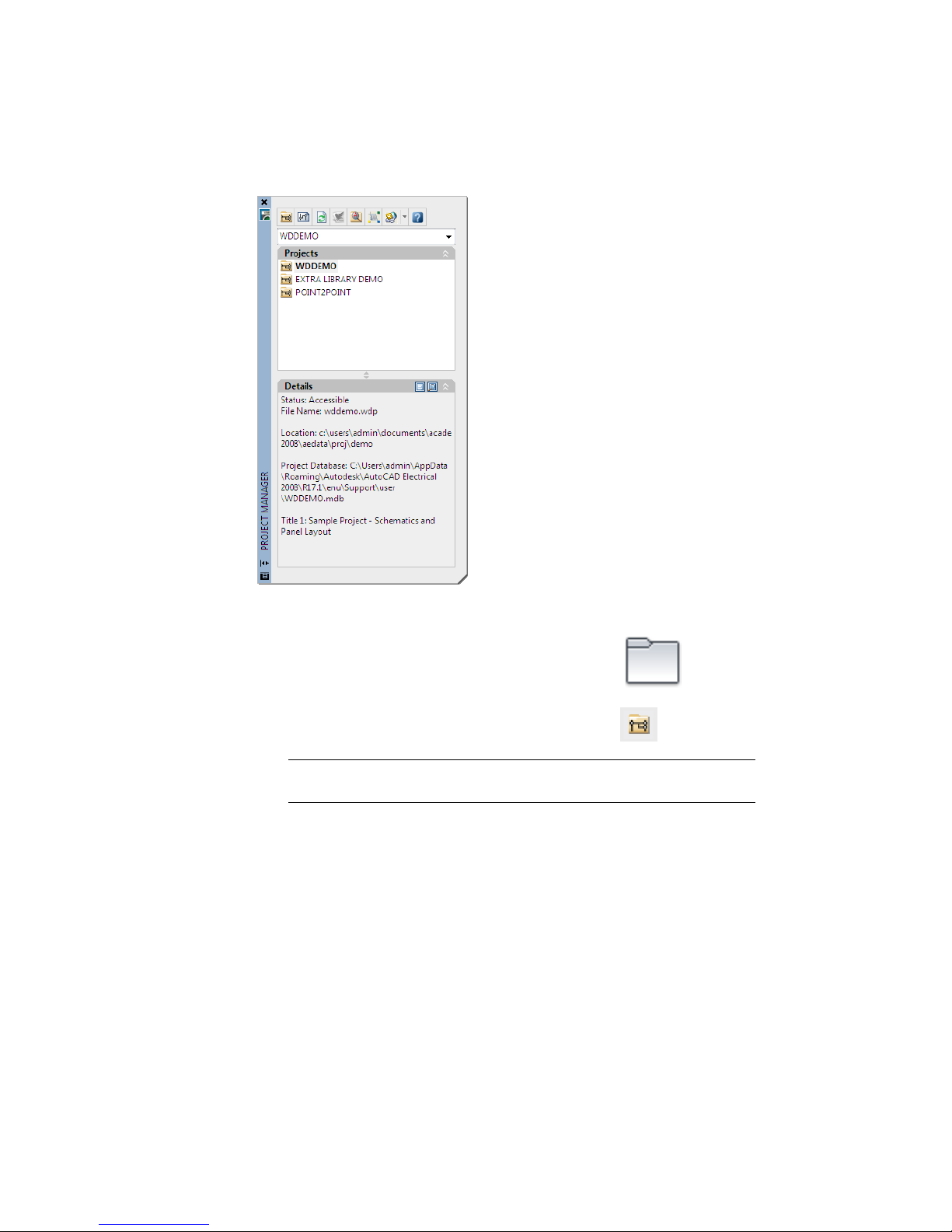
Use the Project Manager to add new drawings, reorder drawing files, and change
project settings. You cannot have two projects open in the Project Manager
with the same project name. By default, the Project Manager is open and docked
on the left-hand side of your screen. You can dock the Project Manager into a
specific location on the screen or hide it until you want to use the project tools.
Right-click the properties icon to display options to move, size, close, dock,
hide, or set the transparency for the Project Manager.
7
Page 14
Create an AutoCAD Electrical project
1 Click Project tab ➤ Project Tools panel ➤ Manager.
2 In the Project Manager, click the New Project tool.
NOTE You can also use the Project Manager to open an existing project. In
the Project Manager, click the project selection arrow and select Open Project.
3 In the Create New Project dialog box, specify:
Name: AEGS
A name must be entered to define any of the project properties. The .wdp
extension is not required in the edit box.
4 Make sure wddemo.wdp is specified in the Copy Settings from Project File
edit box.
8 | Chapter 2 Projects
Page 15

5 Click OK-Properties.
Your new project is added to the current projects list and automatically
becomes the active project.
The Project Properties dialog box displays, where you can modify your project
default settings. All information defined on these tabs are saved to the project
definition file as project defaults and settings.
Set project properties
1 In the Project Properties dialog box, click the Components tab.
2 In the Component Tag Format section, verify that Line Reference is
selected.
This selection creates unique reference-based tags when multiple
components of the same family are located at the same reference location.
When reference-based tagging is used, a suffix variable is required to keep
components of the same family type unique. For example, three push
buttons on line reference 101 could be labeled PB101, PB101A, and
PB101B. Click Suffix Setup to change the suffix variable.
3 Click the Wire Numbers tab.
4 In the Wire Number Format section, verify that Line Reference is selected.
This selection creates unique reference-based wire number tags for
multiple wire networks beginning at the same reference location. When
reference-based numbering is used, a suffix variable is required to keep
wires on the same reference line or in the same reference zone unique.
Click Suffix Setup to change the suffix variable.
Working with Projects | 9
Page 16

5 Review the various options on the different tabs of the Project Properties
dialog box.
NOTE In the Project Properties dialog box, icons indicate whether the settings
apply to project settings or drawing defaults. Settings that apply to project
settings have the project icon next to them and are saved inside the project
definition file (*.wdp). Settings that are saved in the project file as drawing
defaults have the drawing icon next to them. Drawing related data to add
to the project when running the Add Drawing command is saved as Drawing
Custom Properties.
6 Click OK.
Working with Drawings
A single project file can have drawings located in many different directories.
There is no limit to the number of drawings in a project. You can add drawings
to your project at any time. When you create a drawing, using the New
Drawing tool, it is automatically added to the active project.
Many of the drawing settings used by AutoCAD Electrical are stored in a smart
block on the drawing named WD_M.dwg. Each AutoCAD Electrical drawing
should contain only one copy of the WD_M block. If multiple WD_M blocks
are present, the settings cannot be stored and read consistently.
10 | Chapter 2 Projects
Page 17

Create a drawing
1 In the Project Manager, click the New Drawing tool.
2 In the Create New Drawing dialog box, specify:
Name: AEGS11
Description 1: Bill of Materials Report
3 Click Browse next to the Template edit box.
A set of templates (*.dwt files) installed with AutoCAD Electrical contain
settings for various kinds of drawings, such as acad.dwt and
ACAD_ELECTRICAL.dwt.
You can create your own templates, or use any drawing as a template.
You can save a drawing at any stage of completion as a template file.
When you use a drawing as a template, the settings in that drawing are
used in the new drawing. The changes you make to a drawing that is
based on a template do not affect the template file.
AutoCAD Electrical fully supports the use of AutoCAD template files. To
make an AutoCAD drawing compatible with AutoCAD Electrical, select
an AutoCAD Electrical command to modify the drawing.
4 In the Select template dialog box, select ACAD_ELECTRICAL.dwt, and
click Open.
5 In the Create New Drawing dialog box, click OK.
Working with Drawings | 11
Page 18

NOTE You could click OK-Properties to display the Drawing Properties dialog
box. This dialog box has options like the options found in the Project
Properties dialog box. It defines drawing-specific settings that are maintained
inside the WD_M block of the drawing.
6 In the Project Manager, double-click the project name (AEGS) to display
the drawing files. AEGS11 should be the only file in the list.
Add drawings to the project
1 In the Project Manager, right-click AEGS, and select Add Drawings.
2 In the Select Files to Add dialog box, select drawings AEGS01.dwg to
AEGS10.dwg and click Add.
3 When asked whether to apply the project default values to the drawing
settings, click Yes.
The Project Manager lists the files under the AEGS folder. New drawings
that you add from this point on are added at the end of the drawing
order. You now have access to the files required for the exercises in this
book.
NOTE Two projects can reference the same drawing file. However it can lead
to conflicts if both projects try to modify the same drawing with a project-wide
tagging or cross-referencing function.
The drawing order in the Project Manager determines how AutoCAD
Electrical processes the drawings during project-wide operations such as
resequencing and wire numbering.
4 In the Project Manager, right-click the project name, and select Reorder
Drawings.
12 | Chapter 2 Projects
Page 19

5 In the Reorder Drawings dialog box, select AEGS10.dwg and AEGS11.dwg
and click Move Down until the drawings are at the bottom of the list.
6 Click OK.
AEGS11.dwg is now at the bottom of the project drawing file list in the
Project Manager.
NOTE The active drawing displays in bold text in the project drawing list.
You can easily see which file you are working in.
You can add descriptions for each drawing to the project file. You can reuse
drawing descriptions in title block attributes and associate them with AutoCAD
Electrical reports.
Add the description of a drawing you add
1 In the Project Manager, right-click AEGS10.dwg, and select Properties ➤
Drawing Properties.
2 In the Drawing Properties ➤ Drawing Settings dialog box, Drawing File
section, specify:
Description 1: Connector Drawing
3 Click OK.
4 In the Project Manager, select AEGS10.dwg.
Working with Drawings | 13
Page 20

5 In the Project Manager, Details section, review the drawing descriptions.
The drawing details update when you highlight a drawing file and remain
visible until a new drawing file is selected. Displayed information includes
the status, file name, file location, file size, last saved date, and the name
of the last user who modified the file.
Use the Project Manager to preview drawings easily. Moving among drawings
using the up and down keys does not open the drawing. It changes the preview
or details display in the Project Manager.
View drawings in a project
1 In the Project Manager, select AEGS04.dwg.
2 In the Project Manager, Details section, click Preview.
3 Continue to click the drawing name you want to preview or use the up
and down arrow keys to scroll through the drawing files.
4 When you finish viewing the drawings, click Details to return to the
drawing details view.
If a project drawing is currently open and you want to move to the previous
or next drawing in the list of the project, use the Previous Project Drawing
and Next Project Drawing tools. When you move among drawings, any
unsaved changes to the current drawing are saved, the drawing is closed, and
the requested drawing is opened.
View project drawings when a drawing is open
1 In the Project Manager, double-click AEGS04.dwg.
14 | Chapter 2 Projects
Page 21

2 To view the drawings, Click Project tab ➤ Other Tools panel ➤ Previous
DWG.
or Click Project tab ➤ Other Tools panel ➤ Next DWG.
A new window opens and the original window closes when you click the
navigation tools unless you hold the Shift key while clicking the tools.
Working with Drawings | 15
Page 22

16
Page 23

Ladder Style Diagrams
Part 2 of this manual provides information about how to set up and work with ladder style
diagrams.
17
Page 24

18
Page 25

Wires
3
This chapter contains information about wires and how they are used in AutoCAD® Electrical.
About Wires
AutoCAD Electrical treats AutoCAD® line entities as wires when the lines are
placed on an AutoCAD Electrical defined wire layer. The number of wire layers
available in AutoCAD Electrical is unlimited. These lines get tagged with wire
numbers and show up in various wire connection reports.
Two wire segments connect if the end of one wire segment touches or falls
within a small trap distance of any part of the other wire segment. This
connection can be at the end of the other wire or anywhere along the length
of the other wire.
AutoCAD Electrical considers a wire connected to a component if the wire end
falls within a trap distance from the wire connection-point attribute of a
component.
The wire layer for a new wire segment is determined by:
■ Wires that begin or end in space, or begin and end at a component
connection point. They are put on the current layer (if it is a wire layer), or
on the first wire layer AutoCAD Electrical finds in a layer name search.
■ Wires that begin at an existing wire are put on the same layer as the
beginning wire.
■ Wires that begin in space or at a component and end at an existing wire
take on the layer of the ending wire.
19
Page 26

Inserting Wires
You can start or end a wire segment in empty space, from an existing wire
segment, or from an existing component. If you start from a component, the
wire segment snaps to the wire connection terminal closest to your pick point
on that symbol. If the wire segment ends at another wire segment, a DOT
(block name wddot.dwg) is applied if appropriate. If it ends at another
component, the segment connects to the wire connection terminal closest to
your pick point on that symbol.
NOTE When inserting wires, if a wire already occupies a wire connection point,
the new wire is drawn as an angled wire connection.
Insert wiring
1 In the Project Manager, Project Drawing List, double-click AEGS04.dwg.
2 Zoom in on the upper left corner of the drawing. Make sure the hot and
neutral vertical wires are displayed.
3 Click Schematic tab ➤ Edit Wires/Wire Numbers panel ➤ Modify Ladder
drop-down ➤ Add Rung.
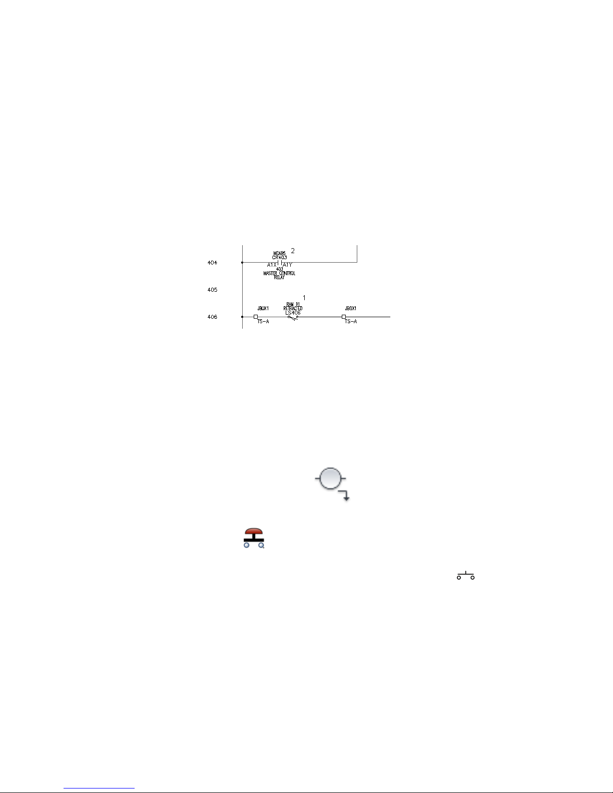
4 Respond to the prompts as follows:
Add rung passing through this location or [wiretype (T)]:
Select a location between the two vertical bus wires beside line reference 403
(1)
Add rung passing through this location or [wiretype (T)]:
Select a location between the two vertical bus wires beside line reference 404,
underneath the newly created rung (2), press ENTER
Two horizontal wires are created automatically between the vertical bus
wires at the closest line reference location.
20 | Chapter 3 Wires
Page 27

Create two vertical wires between two horizontal wires
1 Click Schematic tab ➤ Insert Wires/Wire Numbers panel ➤ Insert Wires
drop-down ➤ Wire.
2 Respond to the prompts as follows:
Specify wire start or [wireType/X=show connections]:
Select the top wire at line reference 403(1)
Specify wire end or [V=start Vertical/H=start
Horizontal/Continue]: Select the lower wire at line reference 404 (2)
The color of temporary graphics changes for a new wire when AutoCAD
Electrical can connect the wire to an existing wire.
Each component wire connection point is displayed as a green x at the
wire connection when you enter X + ENTER during wire insertion. If you
pan or zoom, repeat the command to view the wire connection points.
3 Insert another wire to the right of the new wire.
4 Press ENTER to exit the command.
The inserted wires resemble the following image.
Trimming Wires
After you insert wires, you can trim them. The Trim Wire tool removes wire
segments. You can trim single or multiple wires.
Trimming Wires | 21
Page 28

Trim a wire
1 Click Schematic tab ➤ Edit Wires/Wire Numbers panel ➤ Trim Wire.
2 Respond to the prompts as follows:
Fence/Crossing/Zext/<Select wire to TRIM>:
Specify the wire segment at line reference 404 between the two vertical wires
(1), right-click
Wire segments are trimmed back to a connecting dot, a component, or
completely if neither is encountered along the segment. Any connection
dots that are no longer needed are removed.
The trimmed wire resembles the following image.
22 | Chapter 3 Wires
Page 29

Schematic Components
4
This chapter contains information about schematic components in AutoCAD® Electrical and
inserting them into drawings.
About Schematic Components
An AutoCAD Electrical schematic component is an AutoCAD® block with certain
expected attributes. When inserting components, use AutoCAD Electrical tools
to break wires, assign unique component tags, cross reference related
components, and enter values for catalog information, component descriptions,
and location codes.
AutoCAD Electrical supplies a schematic symbol dialog box for finding and
inserting schematic components. It also triggers some additional features.
■ Automatic wire breaks
■ Component tagging
■ Real-time cross-referencing
■ Component annotation
Inserting Components
AutoCAD Electrical employs a parent/child relationship for schematic
components. A relay coil with a certain number of contacts is represented by
the parent coil symbol and the child contact symbols. When the parent coil
symbol is inserted, it is assigned a unique component tag. When the child
contact symbols are inserted, the child is related to the parent and the parent
tag is assigned to the child symbol.
23
Page 30

In this exercise, you insert components on the wires previously defined in
AEGS04.dwg.
Insert a parent component
1 Zoom in on the upper left corner of the drawing.
2 Click Schematic tab ➤ Insert Components panel ➤ Insert Components
drop-down ➤ Icon Menu.
3 In the Insert Component: JIC Schematic Symbols dialog box, click Relays/
Contacts.
4 In the JIC: Relays and Contacts dialog box, click Relay Coil.
5 Respond to the prompts as follows:
Specify insertion point:
Position the component on the wire at line reference 403 near the neutral wire
and click (1)
The coil symbol breaks the underlying ladder wire and reconnects if you
select directly on the wire or near to it. You did not select close enough
to the wire if the underlying wire did not break. To try again, click Cancel
on the Insert/Edit Component dialog box. Right-click or press ENTER to
repeat the command. Turning on Snap helps (0.125 is a good setting to
use).
This tool inserts components into alignment with underlying wires, it
does not align components side-to-side. If you want to insert components
in neat columns, you have three options: use AutoCAD Snap when
inserting components; use the Scoot command to move components and
connected wires in place; or use the Align Component tool.
6 In the Insert/Edit Component dialog box, verify that the Component
Tag is set to CR403.
24 | Chapter 4 Schematic Components
Page 31

AutoCAD Electrical automatically determines the unique tag name for
the new relay based on the line reference location that you inserted the
symbol on. “CR” indicates that it is a control relay and “403” indicates
that the symbol is on line reference 403. If you inserted this symbol on
line reference 404 then the tag name would be “CR404.”
You can assign a catalog number to the component that can be extracted
into reports. There are two pieces of BOM catalog information:
manufacturer code and catalog number. These values are carried as
invisible attributes on the symbol. You can type in values for each or
select the BOM information from an on-line catalog database file.
7 In the Catalog Data section, click Lookup.
There are three search criteria pull-down lists across the top of the Parts
Catalog dialog box. You can easily change the search criteria to get a
different set of valid catalog numbers. Each time you make a selection
from one of these lists, the catalog selection is filtered.
8 In the Parts catalog dialog box, select the following search criteria:
MANUFACTURER: AB
TYPE: TYPE P
9 Change the catalog assignment to 700-P200A1.
Inserting Components | 25
Page 32

10 Click Catalog Check.
11 In the Bill Of Material Check dialog box, review the BOM information
associated with the selected part number.
Click Close.
12 In the Parts catalog dialog box, click OK.
The selected manufacturer code and catalog number display in the
Insert/Edit Component dialog box. When you click OK on the dialog
box, the values transfers to the symbol.
NOTE Sample catalog information is provided with AutoCAD Electrical in
Access Database format (.mdb). If your company uses its own internal coding
system instead of manufacturer catalog numbers, substitute those numbers
into catalog database files of AutoCAD Electrical. If you use your own system
and reference a number of a vendor, extra user fields are available in all the
sample database files.
13 In the Insert/Edit Component dialog box, Description section, specify:
26 | Chapter 4 Schematic Components
Page 33

Line 1: MASTER CONTROL
Line 2: RELAY
Up to three lines of description text can be entered as a description for
components. If the third description line is unavailable, the symbol does
not carry an attribute for a third line of description.
NOTE You can specify a description by entering text or by clicking Defaults
to select from a list of standard component descriptions.
14 In the Insert/Edit Component dialog box, Location code section, click
Drawing.
AutoCAD Electrical does a quick read of the drawing file and returns a
list of all location codes used so far.
15 In the All Locations - Drawing dialog box, select MCAB5 and click OK.
NOTE You can also include an external “LOC” location list in the project
“LOC” list to help with consistency. To use this feature, create a file called
default.loc and put it in an AutoCAD Electrical search directory. The format
for this text file is each location on its own line in the file with no leading
spaces. You can also create a project-specific file by naming it the same as
your project but with a .loc extension.
16 In the Insert/Edit Component dialog box, the pin values are inserted
based on the selected catalog number:
Pins: 1: K1
Pins: 2: K2
Inserting Components | 27
Page 34

17 In the Insert/Edit Component dialog box, click OK.
Any values entered here are saved as attribute values on the symbol itself.
Relocating Components
You might need to scoot the component if it was not inserted in the correct
location. Use the Scoot tool to select a component or wire number and slide
it back and forth along the wire while keeping everything connected. You can
select a wire or a whole rung of circuitry and scoot it to a new position. If
there are any parent components among the scooted items, you are asked if
you want to retag the scooted components.
The Scoot tool works on wire numbers, components, terminals, PLC I/O
modules, jogs in dashed link lines, signal arrows, wires, and wires with
wire-crossing loops.
28 | Chapter 4 Schematic Components
Page 35

Scoot a component
1 Click Schematic tab ➤ Edit Components panel ➤ Modify Components
drop-down ➤ Scoot.
2 Respond to the prompts as follows:
Select component, wire, or wire number for SCOOT:
Select the component that was just inserted at line reference 403
The cursor changes to a box.
Select component, wire, or wire number for SCOOT: to
Move the cursor to the right and click, right-click to exit the command
The component moves to its new location.
You can use the Scoot tool to grab a component or a wire number and
slide it back and forth along a wire. You can grab a wire or a whole rung
of circuitry and scoot it to a new position, while keeping everything
connected.
The steps to insert a parent component and a child component are the same,
except when you annotate the symbol.
Insert a child component
1 Click Schematic tab ➤ Insert Components panel ➤ Insert Components
drop-down ➤ Icon Menu.
Relocating Components | 29
Page 36

2 In the Insert Component: JIC Schematic Symbols dialog box, click Relays/
Contacts.
3 In the JIC: Relays and Contacts dialog box, click Relay NO Contact.
4 Respond to the prompts as follows:
Specify insertion point:
Position the cursor on the wire at line reference 404 near the hot wire and click
(1)
The Insert/Edit Child Component dialog box displays. Notice that
AutoCAD Electrical did not automatically assign a tag name for the relay
contact; there is just a generic “CR” in the edit box. Determine the relay
contact tag name. A relay contact is a child component that must link
to a parent relay coil on a drawing in the active project. The child gets
the same tag name that is found on the parent relay coil.
Assign the tag name by clicking Parent/Sibling and picking the parent in
the drawing. Or, click Drawing or Project to select from a list of
components with the same family name.
5 In the Insert/Edit Child Component dialog box, Component Tag section,
click Drawing.
6 In the Active Drawing list for FAMILY=”CR” dialog box, select:
MCAB5 CR403 MASTER CONTROL RELAY
30 | Chapter 4 Schematic Components
Page 37

7 Click OK.
The values of the parent are immediately transferred to the contact.
8 In the Insert/Edit Child Component dialog box, verify that the following
options are specified:
Component Tag: CR403
Description: Line 1: MASTER CONTROL
Description: Line 2: RELAY
Cross-reference: 403
Location code: MCAB5
Pins: Pin 1: A1X
Pins: Pin 2: A1Y
Relocating Components | 31
Page 38

9 In the Insert/Edit Child Component dialog box, click OK.
The child component is inserted. It is cross-referenced in real time. The
coil is annotated with the line reference number of the new child contact
and the child contact gets annotated with the line reference location of
the parent coil.
Aligning Components
Align the normally open relay contact with an existing component. After you
insert a component, you can align or edit it as necessary.
Align a component
1 Click Schematic tab ➤ Edit Components panel ➤ Modify Components
drop-down ➤ Align.
32 | Chapter 4 Schematic Components
Page 39
2 Respond to the prompts as follows:
Pick component to align with (Horizontal/<Vertical>):
Select the normally open limit switch component near the hot wire at line
reference 406 (1)
A dashed line is displayed.
Select objects:
Select the previously inserted child contact component near the hot wire at line
reference 404 (2), right-click
The aligned component is placed.
Inserting Components
Now you insert a system reset push button, pilot light, and an emergency stop
push button to make up the circuit.
Insert a system reset button
1 Click Schematic tab ➤ Insert Components panel ➤ Insert Components
drop-down ➤ Icon Menu.
2 In the Insert Component: JIC Schematic Symbols dialog box, click Push
Buttons.
3 In the JIC: Push Buttons dialog box, click Push Button NO.
4 Respond to the prompts as follows:
Specify insertion point:
Inserting Components | 33
Page 40

Position the push button on the wire at line reference 403 near the hot wire
and click (1)
5 In the Insert/Edit Component dialog box, verify the following:
Component Tag: PB403
AutoCAD Electrical automatically assigned the tag name based on the
line reference.
6 In the Descriptions section, specify:
Line 1: SYSTEM
Line 2: RESET
7 In the Location code section, click Drawing.
8 In the All Locations - Drawing dialog box, select OPSTA3 and click OK.
9 In the Insert/Edit Component dialog box, click OK.
Insert a pilot light
1 Click Schematic tab ➤ Insert Components panel ➤ Insert Components
drop-down ➤ Icon Menu.
2 In the Insert Component: JIC Schematic Symbols dialog box, click Pilot
Lights.
3 In the JIC: Pilot Lights dialog box, click Green Press to Test.
4 Respond to the prompts as follows:
Specify insertion point:
34 | Chapter 4 Schematic Components
Page 41

Position the pilot light on the wire at line reference 404 near the neutral wire
and click (2)
TIP Having Snap turned on makes positioning the pilot light easier.
5 In the Insert/Edit Component dialog box, verify:
Component Tag: LT404
6 In the Descriptions section, specify:
Line 1: CONVEYOR
Line 2: ON
7 In the Location code section, click Drawing.
8 In the All Locations - Drawing dialog box, select OPSTA3 and click OK.
9 In the Insert/Edit Component dialog box, click OK.
Insert a push button for emergency stop
1 Click Schematic tab ➤ Insert Components panel ➤ Insert Components
drop-down ➤ Icon Menu.
2 In the Insert Component: JIC Schematic Symbols dialog box, click Push
Buttons.
3 In the JIC: Push Buttons dialog box, click Mushroom Head NC.
4 Respond to the prompts as follows:
Specify insertion point:
Inserting Components | 35
Page 42

Position the push button on the middle of the wire at line reference 403 and
click (3)
5 In the Insert/Edit Component dialog box, verify:
Component Tag: PB403A
AutoCAD Electrical automatically assigned the tag name based on the
line reference. It added the “A” suffix since it is your second push button
on this line reference.
6 In the Descriptions section, specify:
Line 1: EMERGENCY STOP
7 In the Location code section, click Drawing.
8 In the All Locations - Drawing dialog box, select OPSTA3 and click OK.
9 In the Insert/Edit Component dialog box, click OK.
Your finished schematic should resemble the following:
Editing Components
You can go back to a component at any time and make changes. You can
change description, tag, catalog number, location code, terminal numbers,
and rating values using the Edit Component tool.
Insert a child contact
1 Zoom in on the blank ladder rung at line reference 410.
2 Press F9 to turn on SNAP .
36 | Chapter 4 Schematic Components
Page 43

3 Click Schematic tab ➤ Insert Components panel ➤ Insert Components
drop-down ➤ Icon Menu.
4 In the Insert Component: JIC Schematic Symbols dialog box, click Selector
Switches.
5 In the JIC: Selector Switches dialog box, click 2nd+ NC Contact.
6 Respond to the prompts as follows:
Specify insertion point:
Position the selector switch at line reference 410 near the left side of the ladder
and click (1)
7 In the Insert/Edit Child Component dialog box, click OK.
Insert a pilot light
1 Click Schematic tab ➤ Insert Components panel ➤ Insert Components
drop-down ➤ Icon Menu.
2 In the Insert Component: JIC Schematic Symbols dialog box, click Pilot
Lights.
3 In the JIC: Pilot Lights dialog box, click Blue Press to Test.
4 Respond to the prompts as follows:
Editing Components | 37
Page 44
Specify insertion point:
Position the pilot light at line reference 410 near the neutral wire but exactly
in line with the selector switch and click (2)
5 In the Insert/Edit Component dialog box, verify:
Component Tag: LT410
6 In the Descriptions section, specify:
Line 1: MAINT
Line 2: MODE
7 In the Insert/Edit Component dialog box, click OK.
Edit a child contact
1 Press F9 to turn off SNAP .
2 Click Schematic tab ➤ Edit Components panel ➤ Edit Components
drop-down ➤ Edit.
NOTE You can also right-click on a component and select Edit Component
from the context menu.
3 Respond to the prompts as follows:
Select component/cable/location box to EDIT:
Select the selector switch on line reference 410
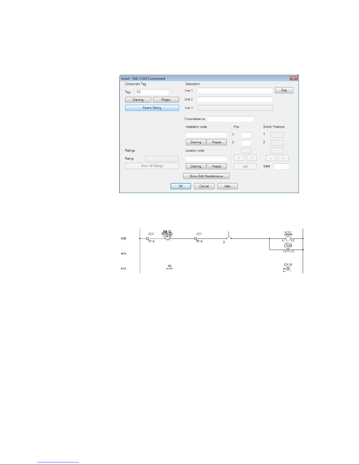
4 In the Insert/Edit Child Component dialog box, Component Tag section,
click Parent/Sibling.
38 | Chapter 4 Schematic Components
Page 45
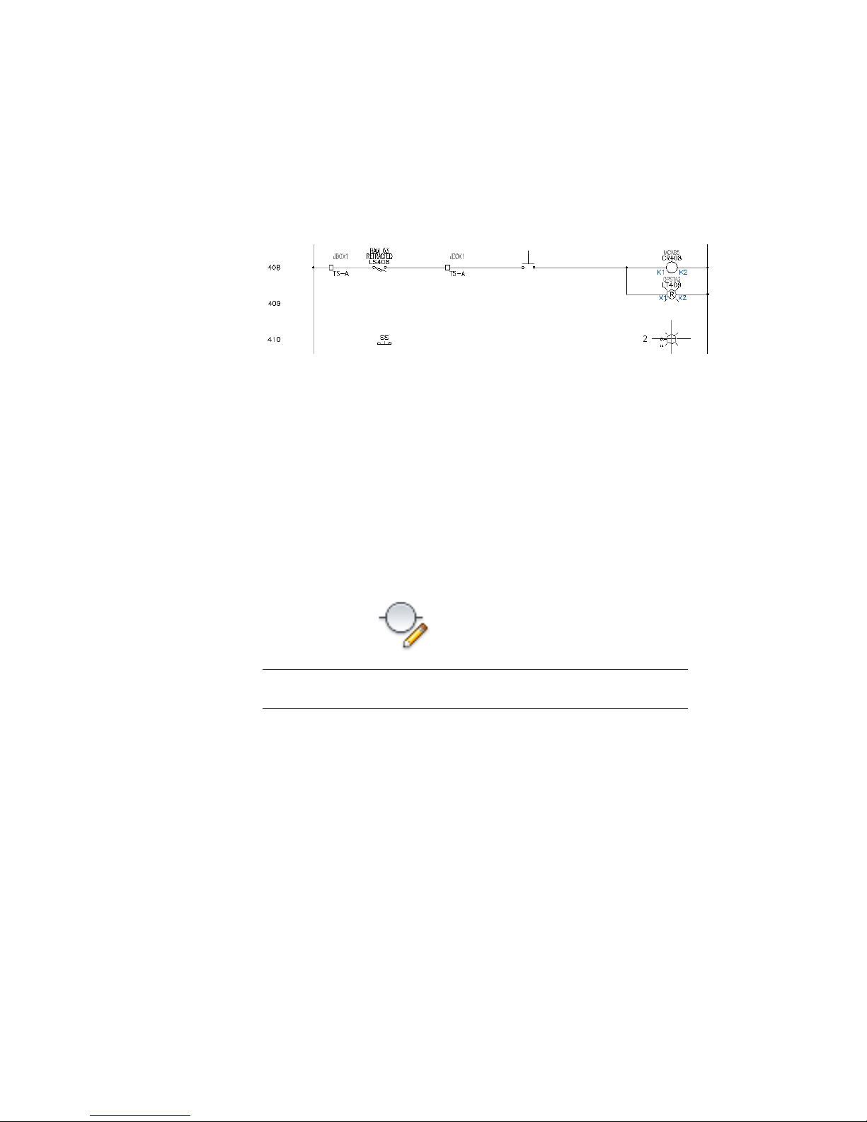
5 Respond to the prompts as follows:
Select component:
Select the bottom sibling contact (3) of the existing switch on line reference 408
AutoCAD Electrical reads the sibling contact and transfers the appropriate
annotation to your new switch contact.
Editing Components | 39
Page 46

6 In the Insert/Edit Child Component dialog box, click OK.
The sibling contact information is displayed on the drawing.
Linking Components
In this exercise, you link the selector switch you inserted to the existing RAM
MODE selector switch residing on line reference 406 through 408 using dashed
link lines.
Connect components using wires
1 Click Schematic tab ➤ Insert Wires/Wire Numbers panel ➤ Insert Wires
drop-down ➤ Wire.
40 | Chapter 4 Schematic Components
Page 47

2 Respond to the prompts as follows:
Specify wire start or [wireType/X=show connections]:
Click the wire connection point on the right-hand side of the switch contact (4)
Specify wire end or [Continue]:
Drag the wire to the right and click the wire connection point on the left-hand
side of the blue pilot light (5)
Specify wire start or [Scoot/wireType/X=show connections]:
Click the left-hand side of the switch contact
Specify wire end or [Continue]:
Drag the wire to the left and click the left-hand vertical bus wire
The wire automatically ends on the bus and inserts a wire connection
dot.
3 Repeat the process to connect the right-hand side of the blue pilot light
to the vertical bus wire.
4 Right-click and select Enter to finish creating the wire connections.
If you lay a wire over the top of a series of components, AutoCAD
Electrical automatically breaks and reconnects to the underlying wire
connection points.
Link components
1 Click Schematic tab ➤ Insert Components panel ➤ Dashed Link Line
drop-down ➤ Link Components with Dashed Line.
2 Respond to the prompts as follows:
Component to link from:
Click the contact of the switch on line reference 408 (6)
Linking Components | 41
Page 48
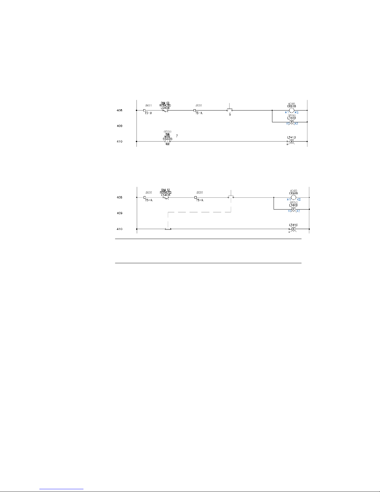
Component to link to:
Click anywhere on your new switch contact (7), right-click
The annotation of the contact is changed to invisible and a dashed link
line is drawn from the bottom of the upper contact to the top of your
new contact.
Your finished schematic should resemble the following:
NOTE The Scoot command is fully compatible with dashed line links. Scooting
one contact left or right causes both links to update automatically. You can
even scoot the horizontal “jog” in the dashed link line up or down.
Editing Catalog Information
Sample catalog information is supplied with AutoCAD Electrical. The
information is held in tables in an Access Database file (.mdb) that is populated
with sample vendor data.
You can use filter criteria in the catalog lookup to display catalog numbers
selectively for a component type.
Filter catalog data
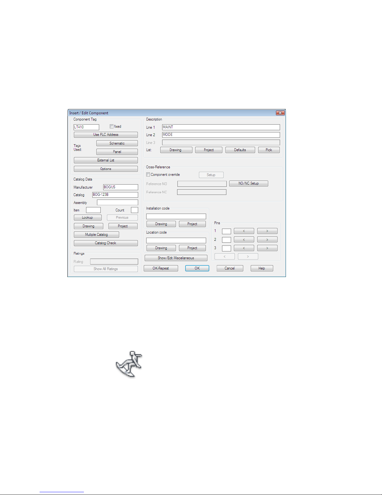
1 Right-click LT410 and select Edit Component.
2 In the Insert/Edit Component dialog box, Catalog Data section, click
Lookup.
42 | Chapter 4 Schematic Components
Page 49

3 In the Parts Catalog dialog box, select:
Manufacturer: AB
Type: 30.5mm
Voltage: 120VAC XFMR
4 Change the catalog assignment to 800T-PT16E.
Add a catalog entry
1 In the Parts Catalog dialog box, click Add.
Editing Catalog Information | 43
Page 50
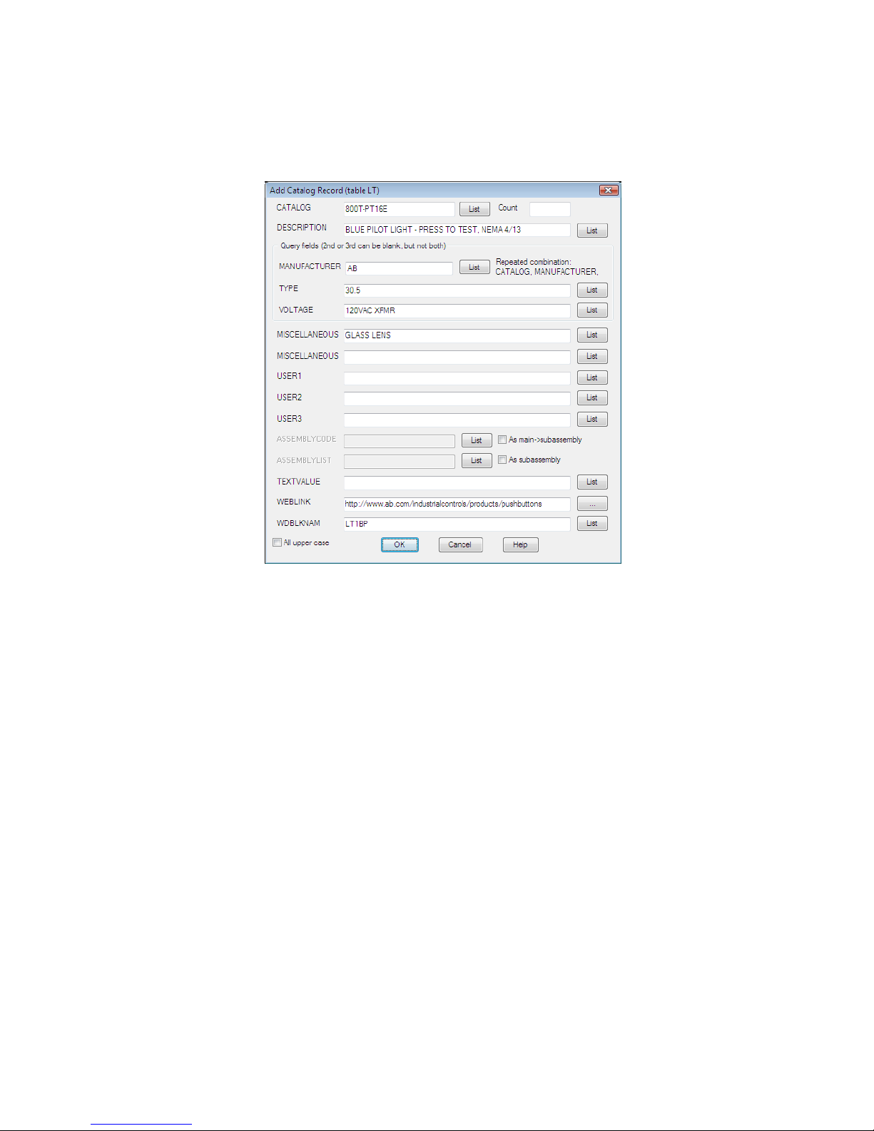
The entries are prefilled with the information for the currently assigned
catalog part number. It is easy to add a new entry with similar
information.
2 In the Add Catalog Record dialog box, specify:
Catalog: BOG-123B
Manufacturer: BOGUS
The catalog lookup works most efficiently when field values that are
meant to be the same are the same in both spelling and capitalization.
The list box beside each field helps you maintain consistency as you add
new catalog items.
3 Click List next to the Description field.
AutoCAD Electrical does a quick scan of the existing catalog file. It collects
and displays a list of all the different description field values found in
the catalog.
4 In the Field Description existing values dialog box, select BLUE PILOT
LIGHT - PRESS TO TEST, NEMA 4/13 and click OK.
44 | Chapter 4 Schematic Components
Page 51

5 In the Add Catalog Record dialog box, click List next to the Type, Voltage
and Miscellaneous fields. Select the values shown in the following image
if not already selected.
AutoCAD Electrical provides three blank user fields for your own internal
use. Each can be a maximum of 24 characters wide and are extracted into
BOM reports along with all the other fields.
NOTE You can add catalog entries with a subassembly. To link a subassembly
with the main, the catalog part numbers share the same codes. In the Edit
Catalog Record dialog box, select As main->sub, enter the ASSYCODE, and
click OK. The ASSYCODE must be unique since it links the main catalog item
with subassembly items. To add the subassembly item, in the Add Catalog
Record dialog box, create a catalog entry, select As sub, enter an
ASSEMBLYLIST code, and click OK.
6 In the Add Catalog Record dialog box, click OK.
As the new entry is being added to the file, the Part Catalog dialog box
displays.
Editing Catalog Information | 45
Page 52
7 In the Parts Catalog dialog box, select the BOG-123B catalog entry and
click OK.
8 In the Insert/Edit Component dialog box, click OK.
Moving Between Symbols
Use the AutoCAD Electrical Surf utility to move from component reference
to reference across the project drawing set quickly.
1 Zoom on the upper left-hand portion of the first ladder column.
2 Click Projects tab ➤ Other Tools panel ➤ Surfer drop-down ➤ Surfer.
3 Click anywhere on relay coil CR407.
46 | Chapter 4 Schematic Components
Page 53

All instances of CR407 appear in the Surf dialog box.
4 Select the reference on sheet 6.
5 Click Go To.
The instance of CR407 on sheet 6 is surfed to and displayed in the drawing
next to the Surf dialog box.
Moving Between Symbols | 47
Page 54

6 Select the reference on sheet 9.
7 Click Go To.
You can edit or delete the component using options in the Surf dialog
box.
8 Double-click the first entry in the Surf dialog box to return to the original
AEGS04.dwg drawing.
9 Click Close.
NOTE Drawing files are saved while surfing if AutoCAD Electrical senses that
a change has been made to the drawing.
Swapping Components
Use the Swap Block tool to swap one component for another (such as swapping
a proximity switch with a limit switch) in a single drawing or project-wide.
Swap switches while keeping wire connections
1 Zoom in on the limit switch on line reference 406.
48 | Chapter 4 Schematic Components
Page 55

2 Click Schematic tab ➤ Edit Components panel ➤ Swap/Update Block.
3 In the Swap Block/ Update Block/ Library Swap dialog box, specify:
Option A: Swap a Block - drawing wide
Pick new block from icon menu
Retain old block scale
Auto re tag if parent swap causes FAMILY change
Attribute Mapping: Use Same Attribute Names (default)
Click OK.
4 In the Insert Component: JIC Schematic Symbols dialog box, click
Miscellaneous Switches.
5 In the JIC: Other Switch Types dialog box, click Proximity Switch NO.
6 Respond to the prompts as follows:
Select component type to swap out: Select the limit switch, LS406
The limit switch symbol disappears and the proximity switch symbol
inserts. All existing text annotation transfers to the new symbols and the
wires reconnect.
Swapping Components | 49
Page 56

Creating Custom Symbols
You can use the Symbol Builder to create an AutoCAD Electrical symbol easily.
This utility builds a smart schematic symbol by either adding AutoCAD
Electrical attributes to the geometry of the symbol, or by converting text
entities to AutoCAD Electrical attributes. You can also use AutoCAD attribute
definition and editing commands to do the same thing. This tool makes the
task easier because you quickly pick and place attributes. It tracks what
attributes are present and checks your work to make sure that any required
attributes are not omitted.
NOTE If you exit out of the Symbol Builder, restart it. On the Select Symbol/Objects
dialog box, click Select objects and select any graphics and attributes you added
so far. You can then start from where you left off.
Create a parent schematic symbol
1 Open AEGS03.dwg.
2 Draw a rectangle anywhere on the drawing.
TIP It is easiest to draw it in the white space on the left-hand side of the
drawing.
50 | Chapter 4 Schematic Components
Page 57

3 Click Schematic tab ➤ Other Tools panel ➤ Symbol Builder
drop-down ➤ Symbol Builder.
4 In the Select Symbol/Objects dialog box, Attribute template section,
browse to the Library path C:\Documents and Settings\All
Users\Documents\Autodesk\Acade {version}\jic125 (or
C:\Users\Public\Documents\Autodesk\Acade {version}\jic125 on a Windows
Vista installation).
5 In the Attribute template section, select Symbol: Horizontal Parent, Type:
Generic.
6 In the Select from drawing section, click Select objects, select the rectangle,
and press ENTER.
7 Select OK.
Adding Attribute Symbols
In this example, you add the attributes: TAG1, DESC1, LOC, INST, FAMILY,
MFG, CAT, and ASSYCODE. You are not limited to these attributes and you
can include your own user-defined attributes on the AutoCAD Electrical block
files.
NOTE The TAG1 attribute is the only one required for a parent schematic symbol.
The other attributes in the Required section are expected on a parent schematic
symbol, however the symbol is recognized as a parent symbol without them.
Add attributes
1 If the Symbol Builder Attribute Editor is not visible,
Adding Attribute Symbols | 51
Page 58

Click Symbol Builder tab ➤ Edit panel ➤ Palette Visibility Toggle.
Use this palette to assign attributes to the rectangle as well as set the
height and justification for each attribute. The palette displays the
AutoCAD Electrical attributes that you can insert and define as part of
the symbol. Once an attribute is inserted on the symbol a check mark is
displayed next to it and you cannot insert it again. AutoCAD Electrical
allows only one insertion of each attribute.
2 In the Symbol Builder Attribute Editor, select TAG1 and click the
Properties tool.
Enter:
Value: PS
It is the default code used as the %F value of the tag format (such as “CR”
, “PB”, “LT”)
Height: 0.125
52 | Chapter 4 Schematic Components
Page 59

Justify: Center
Click OK.
3 Click the Insert Attribute tool.
Insert the attribute above the rectangle.
In the Symbol Builder Attribute Editor, notice the check mark next to
the TAG1 attribute. Continue placing the rest of the attributes.
4 In the Symbol Builder Attribute Editor select DESC1.
Click the Insert Attribute tool.
5 Insert the attribute below TAG1.
6 Insert the LOC and INST attributes as indicated.
7 Insert the FAMILY attribute near the center of the rectangle.
8 With FAMILY still highlighted in the Symbol Builder Attribute Editor,
select the Properties tool.
Enter:
Value: PS
Click OK.
This assigns the %F value to the FAMILY attribute inserted.
Adding Attribute Symbols | 53
Page 60

9 Select MFG and insert near the center of the rectangle. Repeat for CAT
and ASSYCODE.
Adding Wire Connection Points
If a X?TERMxx of the component (for example, "X2TERM01") wire
connection-point attribute lies within the small trap distance of the end of a
wire, then AutoCAD Electrical interprets the component connected to the
wire. The only time the trap distance changes is when you change the Feature
Scale Multiplier in the Drawing (or Project) Properties ➤ Drawing Format
dialog box.
NOTE Components with closely spaced wire connection points may not be
processed properly if the connection points fall within the AutoCAD Electrical trap
distance of one another.
A wire connection attribute can have a related terminal text attribute, TERMxx,
and terminal description attribute, TERMDESCxx. The "xx" is a two-digit
number (starting at 01) that is used to match up with the corresponding
X?TERMxx wire connection attribute.
Insert connection points
1 In the Symbol Builder Attribute Editor, expand the Wire Connection
section.
2 In the Direction / Style list, select Others.
54 | Chapter 4 Schematic Components
Page 61

3 On the Insert Wire Connection dialog box select Terminal Style: Screw.
This terminal style inserts both the graphic to represent the screw and
the wire connection points.
4 Check Use this configuration as default. It directs Symbol Builder to use
the current Terminal Style and Scale as the default in the Symbol Builder
Attribute Editor.
5 Select Connection direction: Left & Top.
It determines the direction the wire attaches to the component.
6 Enter “L” as the value for TERM01 in Pin Information.
7 Select X2TERMDESC01 in Pin Information and click Delete.
8 Click Insert.
9 Select the Insert Wire Connection tool and insert the terminal in the
upper left-hand corner as shown.
NOTE Always use AutoCAD Snap to insert the wire connection point.
10 Back on the Symbol Builder Attribute Editor, expand the Wire Connection
Direction / Style list and select Right & Top / Screw.
Adding Wire Connection Points | 55
Page 62

11 Select the Insert Wire Connection tool and insert the terminal in the
upper right-hand corner.
You can continue to insert wire connections until you press ENTER by
entering the characters indicated in the command line prompt followed
by a space. You can also select from the Direction / Style list.
12 Insert the rest of the terminals as follows:
TERM03: Right
Insertion Point: below TERM02
TERM04: Bottom
Insertion Point: in the lower right-hand corner
TERM05: Bottom
Insertion Point: to the left of TERM04
TERM06: Bottom
Insertion Point: to the left of TERM05
TERM07: Bottom
Insertion Point: to the left of TERM06
13 Press Enter if necessary to return to the command prompt.
14 On the Symbol Builder Attribute Editor, expand the Pins section. Enter
the Pin values as follows:
TERM02 : N
TERM03 : GND
TERM04 : -
TERM05 : -
TERM06 : +
TERM07 : +
56 | Chapter 4 Schematic Components
Page 63

Your drawing should look like the following image:
Saving Symbols
You have two options for saving the symbol: WBlock or Block. WBlock creates
the symbol .dwg file while Block creates the symbol for this drawing file only.
Save and insert the symbol onto a drawing
1 Click Symbol Builder tab ➤ Edit panel ➤ Done.
2 On the Close Block Editor: Save Symbol dialog box, in the Base point
section, click Pick point. Select a point in-line with the top terminals so
that it is easy to place on a wire later.
3 Select WBlock.
4 Enter a file name or accept the default.
Saving Symbols | 57
Page 64

5 Click OK.
6 When asked to insert the symbol, click Yes.
7 Place the symbol on the empty wire on the left-hand side of the drawing.
The wire breaks, the component tag inserts, and the wires connect to the
symbol.
NOTE New symbols you create can also be inserted with the AutoCAD
Electrical Insert Component command. You can add your new symbol to the
icon menu. Or, you can select it from the Type it or Browse dialog box file
selection options in the icon menu.
8 In the Insert/Edit Component dialog box, click OK.
58 | Chapter 4 Schematic Components
Page 65

Circuitry
5
This chapter provides information about working with collections of interconnected
components, or circuits. Circuits can be simple or complex, single or multiple, and with or
without interconnecting wiring. Reusing circuits can both speed up drawing creation and
reduce errors.
Moving an Existing Circuit
When you move a circuit, most of the parent components contained in the
circuit automatically retag since the drawing is set up for reference-based
component tagging. In the process of moving the circuit, you change the
reference locations of the moved components. Related child components update
to match the new parent tags, including references on other drawings in the
project.
NOTE Tagging updates vary depending on your default tagging configurations.
Move the location of a circuit
1 In the Project Manager, Project Drawing List, double-click AEGS02.dwg.
2 Zoom in on the lower left corner of the drawing. Make sure the 3-phase
motor circuit at line reference 215 is visible.
59
Page 66

This circuit has component tags
■ “FU215” on the 3-pole fuse
■ “215CBL” on the multi-conductor cable
■ “DS215” on the disconnect switch
■ “MOT216” on the motor
3 Click Schematic tab ➤ Edit Components panel ➤ Circuit
drop-down ➤ Move Circuit.
4 Respond to the prompts as follows:
Select Objects:
Window select the circuit on line reference 215 to capture the connection wire
and dots that tie in to the vertical bus, right-click
Press F9 to turn on SNAP .
Specify base point or displacement:
Select a base point and then select a point on line reference 214
The circuitry is moved, the affected components are retagged, and
cross-references are updated based on the new line reference. Each of the
listed parent component tags decrement by one. For example, fuse FU215
became FU 214.
5 In the Update Related Components dialog box, click Yes-Update.
60 | Chapter 5 Circuitry
Page 67

Related child references on the active drawing update to match the newly
retagged parent components.
6 In the Update other drawings dialog box, click OK.
Related child components and panel layout references on other drawings
update to match the parent components on the moved circuit.
7 If asked to save the drawing, click OK.
8 Click Project tab ➤ Other Tools panel ➤ Surfer drop-down ➤ Surfer.
9 Select FU214 on the drawing.
The Surf dialog box displays three references on sheet 2 and one reference
on sheet 9.
10 Double-click the reference on Sheet 9.
Surfer goes to the panel layout drawing and zooms in on the physical
representation of this 3-pole fuse. Notice that the physical representation
of the fuse block tag updated because the circuit was moved.
11 Double-click the first entry in the dialog box to return to the original
AEGS02.dwg drawing.
12 Click Close.
Moving the motor circuit up one line reference spacing opened up a bit more
room to add a new circuit below it. The next step is to extend the 3-phase bus
down to line reference 218 and over to the right to begin building a new motor
circuit.
Moving an Existing Circuit | 61
Page 68

Extending the 3-phase bus
1 Click Schematic tab ➤ Edit Wires/Wire Numbers panel ➤ Trim Wire.
2 Respond to the prompts as follows:
Fence/Crossing/Zext/<Select wire to TRIM>:
Click the bottom ends of the three dangling wires, right-click
You can insert vertical or horizontal 3-phase wiring. Three-phase wiring
automatically breaks and reconnects to any underlying components that
it finds in its path. If it crosses any existing wiring, wire-crossing gaps are
inserted.
3 Click Schematic tab ➤ Insert Wires/Wire Numbers panel ➤ Multiple
Bus.
4 In the Multiple Wire Bus dialog box, select:
Horizontal Spacing: 0.5
Vertical Spacing: 0.5
Starting at: Another Bus (Multiple Wires)
Number of Wires: 3
62 | Chapter 5 Circuitry
Page 69

5 Click OK.
6 Respond to the prompts as follows:
Select existing wire to begin multi-phase bus connection:
Select the bottom corner of the left-most vertical bus on line reference 214 as
shown
Select existing wire to begin multi-phase bus connection: to
Pull the cursor down to line reference 218.
Temporary graphics show the proposed routing of the extended bus.
Moving an Existing Circuit | 63
Page 70

7 Click to create the wires.
8 Right-click to exit the command.
The 3-phase bus and wire connection dot symbols are inserted on the
drawing.
Creating a New Motor Circuit
You now construct a new motor circuit on the extended 3-phase bus.
Insert and configure the circuit
1 Click Schematic tab ➤ Insert Components panel ➤ Circuit Builder
drop-down ➤ Circuit Builder.
2 The Circuit Selection dialog box displays.
64 | Chapter 5 Circuitry
Page 71

3 Expand 3ph Motor Circuit.
4 Select Horizontal - FVNR - non reversing.
5 Change the Rung Spacing: Horizontal to 0.5.
6 Select Configure.
7 Specify insertion point at rung 217.
Creating a New Motor Circuit | 65
Page 72

Circuit Configuration
A circuit is made up of individual circuit elements and the wiring that connects
them. Circuit Builder inserts a template drawing. This template contains the
base wiring for the circuit and strategically positioned “marker blocks”.
The “marker blocks” control what circuit elements are presented in the Circuit
Configuration dialog box. For example, a “marker block” indicates the need
for a Disconnecting Means in the circuit. Various options for the Disconnecting
Means are presented in the dialog box. The option selected for this circuit
element is inserted at the location of the “marker block”. Circuit Builder
dynamically builds the complete circuit based on the selections you make on
this dialog box.
1 In the Circuit Elements section, select Motor symbol.
In the Select section, select Motor: 3ph motor,
Ground/PE wire connection: No.
2 In the Circuit Elements section, select Disconnecting Means.
In the Select section, select Main Disconnect: Fuses,
Include N.O. auxiliary contact: No.
66 | Chapter 5 Circuitry
Page 73

Setup & Annotation section: The options within this section change
according to your selections in the Circuit Elements and Select sections.
Type in values or select the Browse button to access a lookup table.
Select an entry from the lookup table to obtain values for the individual
settings. The catalog lookup is opened if the circuit option is a component.
3 In the Circuit Elements section, select Control transformer and circuit -
non-reversing.
In the Select section, select Include control circuit: None.
Creating a New Motor Circuit | 67
Page 74

4 In the Circuit Elements section, select Power Factor correction.
In the Select section, select Include power factor correction capacitor:
None.
68 | Chapter 5 Circuitry
Page 75

5 In the Circuit Elements section, select Overloads.
In the Select section, select Overload elements: Thermal,
Include N.O. auxiliary contact: No.
Creating a New Motor Circuit | 69
Page 76

6 In the Circuit Elements section, select Motor terminal connections.
In the Select section, select Motor connection terminals: Round.
70 | Chapter 5 Circuitry
Page 77

7 In the Circuit Elements section, select Cable marker.
In the Select section, select Cable: None.
Creating a New Motor Circuit | 71
Page 78

8 In the Circuit Elements section, select Safety disconnect at the load.
In the Select section, select Safety disconnect: Disconnect switch,
Include N.O. auxiliary contact: No.
72 | Chapter 5 Circuitry
Page 79

9 Select the Insert all circuit elements tool. Circuit Builder inserts each of
the selected circuit elements.
10 Select Done.
NOTE See the Circuit Builder topics later in this section for more examples.
Multi-level terminals
1 In the Project Manager, Project Drawing List, double-click AEGS02.dwg.
Creating a New Motor Circuit | 73
Page 80

2 Click Schematic tab ➤ Edit Components panel ➤ Edit Components
drop-down ➤ Edit.
3 Select the round terminal on rung 217. The Insert/Edit Terminal Symbol
dialog box displays, where you can annotate the terminal properties and
associations.
4 In the Insert/Edit Terminal Symbol dialog box, Project List section, select
Tag Strip TB.
5 Enter Location: MCAB5 and Number: 10.
6 Click Details >>.
7 In the Catalog Data section, click Catalog Lookup.
8 On the Parts Catalog dialog box, select:
Manufacturer: SIEMENS
Type: MULTI-LEVEL
Rating: 20 AMPS
9 Select part 8WA1 011-3JF16 and click OK.
74 | Chapter 5 Circuitry
Page 81

The Manufacturer and Catalog information for the selected part displays
in the Catalog Data section of the Insert/Edit Terminal Symbol dialog
box.
10 On the Insert/Edit Terminal Symbol dialog box, click OK.
11 Click Schematic tab ➤ Edit Components panel ➤ Edit Components
drop-down ➤ Edit.
12 Select the middle terminal between rungs 217 and 218. The Insert/Edit
Terminal Symbol dialog box displays.
13 In the Insert/Edit Terminal Symbol dialog box, Project List section, select
Tag Strip TB.
14 Enter Location: MCAB5 and Number: 11.
Modify multi-level terminal associations
1 On the Insert/Edit Terminal Symbol dialog box, Modify
Properties/Associations section, click Add/Modify.
2 On the Add/Modify Association dialog box, Select Association section,
expand the active project node. The active node is bold in the list.
Creating a New Motor Circuit | 75
Page 82

3 Select the terminal block node you inserted on line reference 217 (10, ,
(3)).
The terminal numbers defined on the block are listed, separated by
commas. The number of levels defined in the block properties displays
at the end of the node string in parenthesis. For example, 1,21,GND (3).
If a level is not represented on the schematic, it is represented by empty
space: 1, , GND (3). If a terminal has been assigned to the level, but the
terminal does not have a number assignment, it is represented by ‘???’:
1,???,GND (3).
NOTE The grid to the right populates with the definition for the selected
terminal: Level 1 has Label = TOP, Number = 10, Reference = 2,217.
4 Select Level 2 in the grid and click Associate.
76 | Chapter 5 Circuitry
Page 83

Once you click Associate, the middle level updates with the terminal
number in the grid in the Active Association section of the dialog box.
5 Click OK.
The level assignments display in the Properties/Associations section of
the Insert/Edit Terminal Symbol dialog box. Notice that the terminal is
three levels and levels 1 and 2 are now assigned.
6 On the Insert/Edit Terminal Symbol dialog box, click OK.
Creating a New Motor Circuit | 77
Page 84

7 Click Schematic tab ➤ Edit Components panel ➤ Edit Components
drop-down ➤ Edit.
8 Select the bottom terminal on rung 218. The Insert/Edit Terminal Symbol
dialog box displays.
9 In the Insert/Edit Terminal Symbol dialog box, Project List section, select
Tag Strip TB.
10 Enter Location: MCAB5 and Number: 12.
11 On the Insert/Edit Terminal Symbol dialog box, Modify
Properties/Associations section, click Add/Modify.
12 On the Add/Modify Association dialog box, Select Association section,
expand the active project node.
13 Select the terminal block node you inserted on line reference 217 (10,11,
(3)). Notice that the node properties updated to reflect that levels 1 and
2 are assigned and that level 3 is still blank/available.
14 Select Level 3 in the grid and click Associate.
Once you click Associate, the bottom level updates with the terminal
number in the grid in the Active Association section of the dialog box.
You can rearrange the levels by selecting a level and clicking Move Up
or Move Down.
78 | Chapter 5 Circuitry
Page 85

15 Click OK.
The level assignments display in the Properties/Associations section of
the Insert/Edit Terminal Symbol dialog box. Notice that levels 1, 2, and
3 are now assigned.
16 On the Insert/Edit Terminal Symbol dialog box, click OK.
Creating a New Motor Circuit | 79
Page 86

Insert a ground
1 Click Schematic tab ➤ Insert Wires/Wire Numbers panel ➤ Wire.
2 Respond to the prompts as follows:
Specify wire start or [wireType/ X=show connections]:
Select a point on the motor symbol near its 5 o’clock position
Specify wire end or [Continue]:
Move the cursor down past the bottom pole, left-click, pull the wire to the left
and down, then left-click to insert the wire, press ESC to exit the command
3 Click Schematic tab ➤ Insert Components panel ➤ Copy Component.
4 Respond to the prompts as follows:
Select component to copy:
Select the ground symbol from the circuit on line reference 214
Specify insertion point: Select the end of the motor ground wire
80 | Chapter 5 Circuitry
Page 87

Saving and Inserting Standard Circuits
AutoCAD®Electrical makes saving and inserting pre-drawn circuits easy and
convenient. You can save and insert from a user circuits page on the Insert
Component icon menu or you can use the normal AutoCAD® WBlock
command to save selected circuitry to disk and an Insert Circuit command to
insert WBlocked circuits into the active drawing.
Save your circuit for use in the future
1 Zoom around the circuit so that it fills your screen.
2 Click Schematic tab ➤ Edit Components panel ➤ Circuit
drop-down ➤ Save Circuit To Icon Menu.
3 On the Save Circuit to Icon Menu dialog box, click Add ➤ New circuit.
4 On the Create New Circuit dialog box, specify:
Name: Motor Circ - Fusible DS
Image file: Active and Create PNG from current screen image
File name: UserCirc1
5 Click OK.
6 Respond to the prompts as follows:
Saving and Inserting Standard Circuits | 81
Page 88

Base point:
Select the left-most wire connection point where the circuit ties into the left-hand
vertical bus wire
Select objects:
Window around the circuit from left to right to capture all the components and
wiring, but exclude the vertical bus, press ENTER
7 On the Save Circuit to Icon Menu dialog box, click OK.
The circuit is saved to your AutoCAD Electrical user folder and can be
quickly accessed from the Insert Component icon menu or from the
Insert Saved Circuit tool.
The new motor has a 3-pole motor contactor child reference but there is not
a parent motor starter relay coil to operate it. The motor start coil circuit must
be added on a control schematic in the project drawing set and linked back
to the new motor circuit.
Insert motor start coil circuit to control schematic
1 Open AEGS04.dwg.
2 Zoom on the upper-right hand ladder column so the full circuit on line
reference 422-423 is displayed.
82 | Chapter 5 Circuitry
Page 89
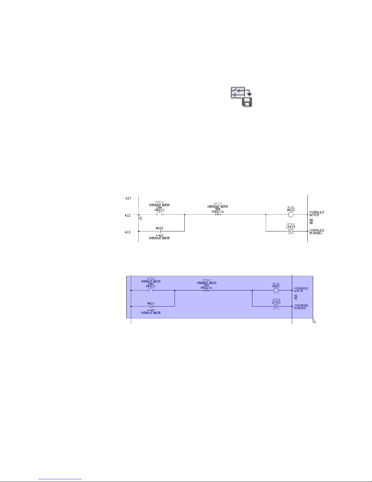
3 Click Schematic tab ➤ Edit Components panel ➤ Circuit
drop-down ➤ Save Circuit To Icon Menu.
4 On the Save Circuit to Icon Menu dialog box, click Add ➤ New circuit.
5 On the Create New Circuit dialog box, specify:
Name: Motor starter circ
Image file: Active and Create PNG from current screen image
File name: UserCirc2
Click OK.
6 Respond to the prompts as follows:
Base point: Select the left-most wire connection point at line reference 422
Select objects:
Window around the circuit from left to right to capture all the components and
wiring, but exclude the vertical bus, press ENTER
7 On the Save Circuit to Icon Menu dialog box, click OK.
Insert a circuit you saved for re-use
1 Pan to display the blank area between line references 426 - 432.
Saving and Inserting Standard Circuits | 83
Page 90
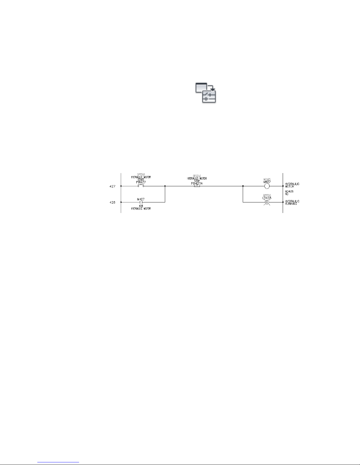
2 Click Schematic tab ➤ Insert Components panel ➤ Circuit
drop-down ➤ Insert Saved Circuit.
3 In the JIC: Saved User Circuits dialog box, select the Motor starter circ
button.
4 In the Circuit Scale dialog box, click OK.
5 Respond to the prompts as follows:
Specify insertion point:
Place the circuit insertion point on the vertical bus wire at line reference 427,
left-click to insert the circuit.
The circuit inserts and updates. Tags automatically update to reflect the
new line reference number, and parent/child relationships defined inside
of the circuit update accordingly.
6 Right-click the M427 coil symbol and select Edit Component.
7 In the Insert/Edit Component dialog box, specify:
Description Line 2: MOTOR NO. 2
Click OK.
8 In the Update Related Components dialog box, click Yes-Update.
Linking the parent coil to the child contactor
1 Open AEGS02.dwg and zoom on the untagged 3-pole motor
contact/overloads on line reference 217.
2 Right-click the “M” contact and select Edit Component.
The Insert/Edit Child Component is displayed. Enter the exact parent
coil tag into the Component Tag box to establish the link between the
parent and the child contacts. Currently the Component Tag is M.
84 | Chapter 5 Circuitry
Page 91

3 In the Insert/Edit Child Component dialog box, Component Tag section,
click Project.
4 In the Complete Project list for Family=”M” dialog box, select M427
HYDRAULIC MOTOR NO. 2 and click OK.
The tag M427 is now displayed in the Component Tag edit box. Notice
that the description, cross-reference, and location code boxes have also
updated.
5 In the Insert/Edit Child Component dialog box, click OK.
6 In the Update linked components dialog box, click OK.
The components are now linked. If you go back to drawing AEGS04.dwg
and look at the motor starter coil, it shows references to these three child
contacts (plus one seal contact around PB427).
Saving and Inserting Standard Circuits | 85
Page 92

Using the icon menu to add a motor
1 Reopen drawing AEGS04.dwg and zoom to the blank area at line references
430-431.
2 Repeat the steps for inserting the saved Motor starter circ circuit.
3 In the Circuit Scale dialog box, click OK.
4 Insert the circuit at line reference 430.
5 Right-click the M430 coil symbol, and select Edit Component.
6 In the Insert/Edit Component dialog box, specify:
Description Line 2: MOTOR NO. 3
Click OK.
7 In the Update related components dialog box, click Yes-Update.
8 Open drawing AEGS02.dwg and zoom to the blank area at line references
204-206.
9 Repeat the steps for inserting a saved circuit, but this time insert the
Motor Circ - Fusible DS circuit.
10 In the Circuit Scale dialog box, click OK.
11 Respond to the prompts as follows:
Specify insertion point:
Position the motor circuit so that the insertion point lands on the left-hand
vertical bus at line reference 204, left-click to insert the circuit.
Notice that the fuse, disconnect, and motor automatically retag based
on their reference locations.
12 Right-click the M child motor contact symbol, and select Edit Component.
13 In the Insert/Edit Child Component dialog box, Component Tag section,
click Project.
86 | Chapter 5 Circuitry
Page 93

14 In the Complete Project list for Family=”M” dialog box, select M430
HYDRAULIC MOTOR NO. 3 and click OK.
The tag M430 is now displayed in the Component Tag edit box. Notice
that the description, cross-reference, and location code boxes have also
updated.
15 In the Insert/Edit Child Component dialog box, click OK.
16 In the Update linked components dialog box, click OK.
You can now renumber your terminals manually or project-wide.
Renumber terminals
1 Enter AETERMRENUM at the command prompt.
2 On the Project-wide Schematic Terminal Renumber dialog box, select:
Include Installation/Location in terminal strip Tag-ID match
Starting Terminal Number = 1
3 In the Tag-ID section, click Drawing.
4 On the Terminal Tag-ID List dialog box, select Tag-ID = TB and click OK.
5 On the Project-wide Schematic Terminal Renumber dialog box, click OK.
6 On the Select Drawings to Process dialog box, click Do All and click OK.
7 If asked to save the drawing, click OK.
You can modify an existing terminal to make it a multi-level terminal block
and then associate terminals to the master terminal block.
Modify terminal properties
1 Right-click terminal 4 on line reference 211 and select Edit Component.
2 On the Insert/Edit Terminal Symbol dialog box, Catalog Data section,
delete the Manufacturer and Catalog information.
Saving and Inserting Standard Circuits | 87
Page 94
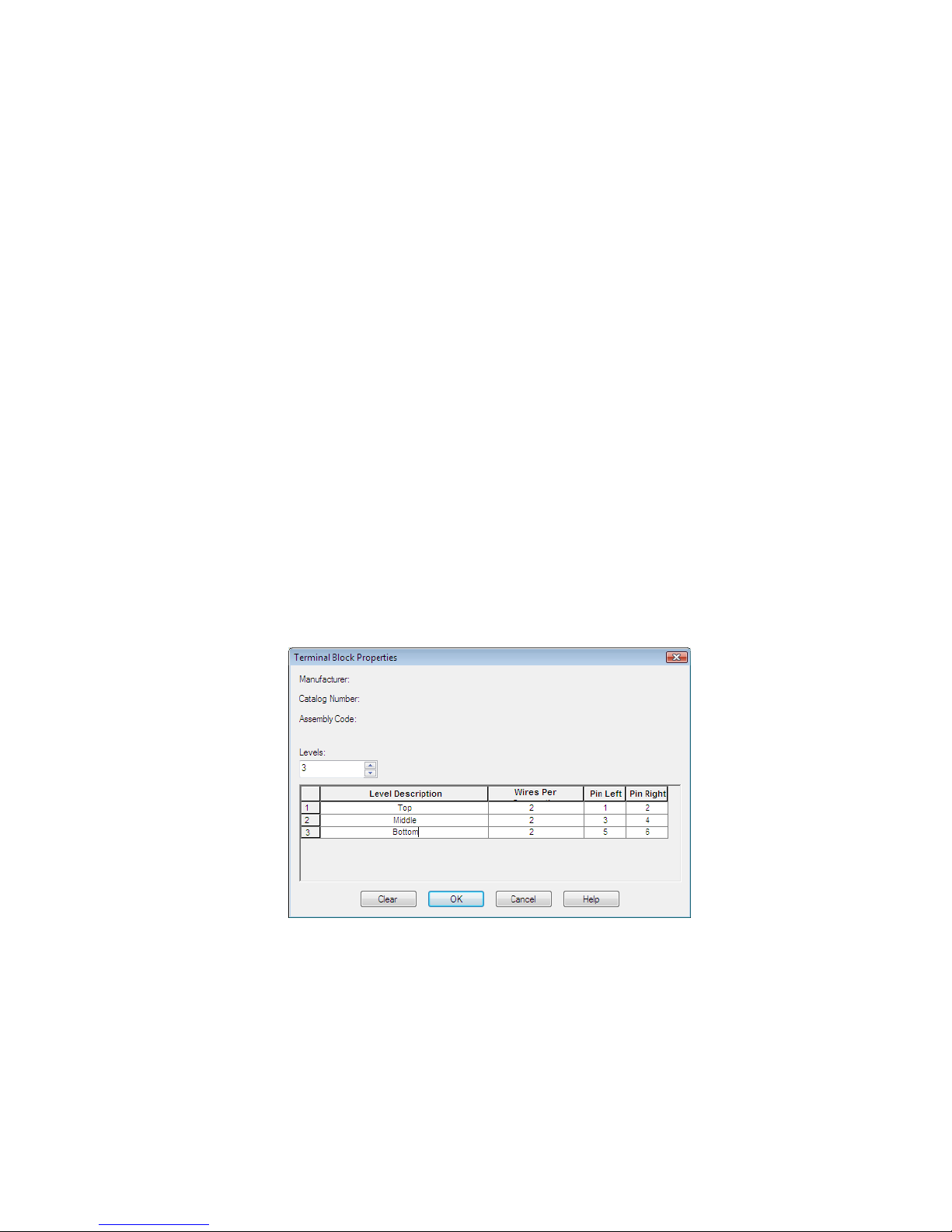
3 In the Modify Properties/Associations section, click Block Properties.
4 On the Terminal Block Properties dialog box, specify:
Levels: 3
Level 1
Level Description: Top
Wires Per Connection: 2
PinL: 1
PinR: 2
Level 2
Level Description: Middle
Wires Per Connection: 2
PinL: 3
PinR: 4
Level 3
Level Description: Bottom
Wires Per Connection: 2
PinL: 5
PinR: 6
Click OK.
88 | Chapter 5 Circuitry
Page 95

Notice on the Insert/Edit Terminal Symbol dialog box,
Properties/Associations section that the block now has three levels.
Terminal 4 is assigned to the top level of the block.
5 On the Insert/Edit Terminal Symbol dialog box, click OK.
6 On the Update other drawings dialog box, click OK.
7 If asked to save the drawing, click OK.
Associate terminals
1 Click Schematic tab ➤ Edit Components panel ➤ ➤ Associate
Terminals.
2 Respond to the prompts as follows:
Select “Master” terminal: Select terminal 4 on line reference 211
Pick terminal: Select terminal 5
Pick terminal: Select terminal 6, right-click
Saving and Inserting Standard Circuits | 89
Page 96

NOTE The command prompt area indicates that the terminal was added as
level 02 or level 03 once you pick the terminal.
3 Right-click terminal 6 and select Edit Component.
On the Insert/Edit Terminal Symbol dialog box, Properties/Associations
section, all three levels have been assigned. You can now move a terminal
to another level using the Add/Modify Association dialog box.
4 On the Insert/Edit Terminal Symbol dialog box, Modify
Properties/Associations section, click Add/Modify.
5 On the Add/Modify Association dialog box, Active Association section,
highlight level 3 in the grid and click Move Up.
90 | Chapter 5 Circuitry
Page 97

The grid updates to reflect the move. Notice that terminal 6 is now
assigned to level 2.
6 Click OK.
7 On the Insert/Edit Terminal Symbol dialog box, click OK.
8 If asked to update related components, click Yes-Update.
Add wire tee markers to your circuits
1 Pan your view so the circuit on line reference 204 is visible.
2 Click Schematic tab ➤ Insert Wires/Wire Numbers panel ➤ Insert Dot,
Tee Markers drop-down ➤ Insert Dot Tee Markers.
3 Respond to the prompts as follows:
Specify insertion point:
Select the connection points at the vertical 3-phase bus for each wire
4 Insert dot tee markers for the circuit on line reference 204.
5 Right-click to exit the command.
Inserting Saved Circuits Using WBlock
Another method for saving and inserting circuits is to use the AutoCAD WBlock
command to save the circuit to disk. A separate Insert Circuit command is
used to browse to a selected saved circuit and insert it into the active drawing.
This method allows unlimited circuits to be constructed and saved to disk.
They can be arranged into a set of shared subfolders for easy browsing and
retrieval using the Insert Circuit command.
Inserting Saved Circuits Using WBlock | 91
Page 98
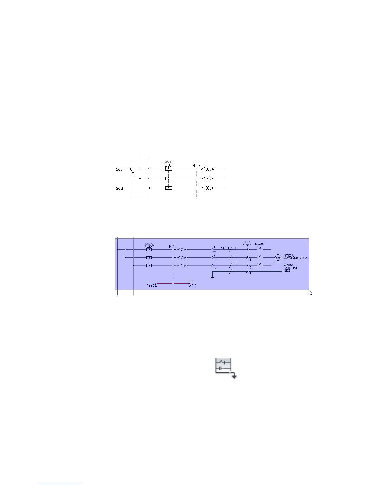
Saving a circuit using WBlock
1 Pan to display the 3-phase motor circuit at line references 207 - 209.
2 Enter wblock at the command line and press ENTER.
3 In the Write Block dialog box, click Pick point.
4 Respond to the prompts as follows:
Specify insertion base point:
Select the intersection of the left vertical bus with the upper horizontal wire at
line reference 207
5 In the Write Block dialog box, click Select objects.
6 Respond to the prompts as follows:
Select objects: Window from left to right around the full circuit, right-click
7 In the Write Block dialog box, enter a name for the saved circuit. Take
note of the location where the drawing file is being saved.
8 Click OK.
Inserting a WBlocked circuit
1 Click Schematic tab ➤ Insert Components panel ➤ Circuit
drop-down ➤ Insert WBlocked Circuit.
92 | Chapter 5 Circuitry
Page 99

2 In the Insert Wblocked Circuit dialog box, browse to the folder containing
the circuit you saved.
3 Select the WBlocked motor circuit, and click Open.
4 In the Circuit Scale dialog box, select:
Move all lines to wire layers
Keep all source arrows
Update circuit’s text layers as required
Click OK.
5 Respond to the prompts as follows:
Specify insertion point: Select any blank spot on your drawing
The parent component tags that are not set to Fixed automatically retag
based on the insertion point. It is like the behavior when inserting a
circuit using the icon menu method.
6 Delete the circuit.
Inserting a One-line Motor Circuit
In this exercise, you insert and configure a one-line motor control circuit using
Circuit Builder.
1 Start a new blank drawing and save it as One-Line.dwg.
2 In Project Manager, right-click on the project name and select Add Active
Drawing.
3 Using the Insert Wire tool, add a horizontal one-line bus.
Insert the one-line circuit
1 Click Schematic tab ➤ Insert Components panel ➤ Circuit Builder
drop-down ➤ Circuit Builder.
The Circuit Selection dialog box displays.
2 Expand One-line Motor Circuit.
3 Select Vertical - FVNR - non reversing.
Inserting a One-line Motor Circuit | 93
Page 100

4 Click Configure.
5 Specify an insertion point on the one-line bus.
The Circuit Configuration dialog box displays.
6 In the Circuit Elements section, select Motor Setup.
94 | Chapter 5 Circuitry
 Loading...