

Autodesk 18506-091462-9305 - Architectural Desktop 2006, ARCHITECTURAL DESKTOP 2006 Update Manual
Page 1

AUTODESK
®
ARCHITECTURAL DESKTOP
2006
Imperial Tutorials Update
August 2005
Page 2

Copyright©2005 Autodesk, Inc.
All Rights Reserved
This publication, or parts thereof, may not be reproduced in any form, by any method, for any purpose.
AUTODESK, INC., MAKES NO WARRANTY, EITHER EXPRESS OR IMPLIED, INCLUDING BUT NOT LIMITED TO ANY IMPLIED WARRANTIES
OF MERCHANTABILITY OR FITNESS FOR A PARTICULAR PURPOSE REGARDING THESE MATERIALS, AND MAKES SUCH MATERIALS
AVAILABLE SOLELY ON AN "AS-IS" BASIS.
IN NO EVENT SHALL AUTODESK, INC., BE LIABLE TO ANYONE FOR SPECIAL, COLLATERAL, INCIDENTAL, OR CONSEQUENTIAL DAMAGES
IN CONNECTION WITH OR ARISING OUT OF PURCHASE OR USE OF THESE MATERIALS. THE SOLE AND EXCLUSIVE LIABILITY TO AUTODESK,
INC., REGARDLESS OF THE FORM OF ACTION, SHALL NOT EXCEED THE PURCHASE PRICE OF THE MATERIALS DESCRIBED HEREIN.
Autodesk, Inc., reserves the right to revise and improve its products as it sees fit. This publication describes the state cation, and may not reflect the product at all times
in the future.
Autodesk Trademarks
The following are registered trademarks of Autodesk, Inc., in the USA and/or other countries: 3D Props, 3D Studio, 3D Studio MAX, 3D Studio VIZ, 3DSurfer, ActiveShapes,
ActiveShapes (logo), Actrix, ADI, AEC Authority (logo), AEC-X, Animator Pro, Animator Studio, ATC, AUGI, AutoCAD, AutoCAD LT, AutoCAD Map, Autodesk, Autodesk
Inventor, Autodesk (logo), Autodesk MapGuide, Autodesk University (logo), Autodesk View, Autodesk WalkThrough, Autodesk World, AutoLISP, AutoSketch, Biped,
bringing information down to earth, CAD Overlay, Character Studio, Cinepak, Cinepak (logo), Codec Central, Combustion, Design Your World, Design Your World (logo),
Discreet, EditDV, Education by Design, gmax, Heidi, HOOPS, Hyperwire, i-drop, Inside Track, Kinetix, MaterialSpec, Mechanical Desktop, NAAUG, ObjectARX, PeopleTracker,
Physique, Planix, Powered with Autodesk Technology (logo), RadioRay, Revit, Softdesk, Texture Universe, The AEC Authority, The Auto Architect, VISION, Visual, Visual
Construction, Visual Drainage, Visual Hydro, Visual Landscape, Visual Roads, Visual Survey, Visual Toolbox, Visual TugBoat, Visual LISP, Volo, WHIP!, and WHIP! (logo).
The following are trademarks of Autodesk, Inc., in the USA and/or other countries: 3ds max, AutoCAD Architectural Desktop, AutoCAD Learning Assistance, AutoCAD LT
Learning Assistance, AutoCAD Simulator, AutoCAD SQL Extension, AutoCAD SQL Interface, Autodesk Map, Autodesk Streamline, AutoSnap, AutoTrack, Built with ObjectARX
(logo), Burn, Buzzsaw, Buzzsaw.com, Cinestream, Cleaner, Cleaner Central, ClearScale, Colour Warper, Content Explorer, Dancing Baby (image), DesignCenter, Design
Doctor, Designer's Toolkit, DesignProf, DesignServer, Design Web Format, DWF, DWG Linking, DXF, Extending the Design Team, GDX Driver, gmax (logo), gmax ready
(logo),Heads-up Design, IntroDV, jobnet, ObjectDBX, onscreen onair online, Plans & Specs, Plasma, PolarSnap, ProjectPoint, Reactor, Real-time Roto, Render Queue,
Visual Bridge, Visual Syllabus, and Where Design Connects.
Autodesk Canada Inc. Trademarks
The following are registered trademarks of Autodesk Canada Inc. in the USA and/or Canada, and/or other countries: discreet, fire, flame, flint, flint RT, frost, glass, inferno,
MountStone, riot, river, smoke, sparks, stone, stream, vapour, wire.
The following are trademarks of Autodesk Canada Inc., in the USA, Canada, and/or other countries: backburner, backdraft, Multi-Master Editing.
Third Party Trademarks
All other brand names, product names or trademarks belong to their respective holders.
Third Party Software Program Credits
ACIS Copyright © 1989-2001 Spatial Corp. Portions Copyright © 2002 Autodesk, Inc.
Copyright © 1997 Microsoft Corporation. All rights reserved.
International CorrectSpell ™ Spelling Correction System © 1995 by Lernout & Hauspie Speech Products, N.V. All rights reserved.
InstallShield ™ 3.0. Copyright © 1997 InstallShield Software Corporation. All rights reserved.
PANTONE ® Colors displayed in the software application or in the user documentation may not match PANTONE-identified standards. Consult current PANTONE Color
Publications for accurate color. PANTONE ® and other Pantone, Inc. trademarks are the property of Pantone, Inc. © Pantone, Inc., 2002
Pantone, Inc. is the copyright owner of color data and/or software which are licensed to Autodesk, Inc., to distribute for use only in combination with certain Autodesk
software products. PANTONE Color Data and/or Software shall not be copied onto another disk or into memory unless as part of the execution of this Autodesk software
product.
Portions Copyright © 1991-1996 Arthur D. Applegate. All rights reserved.
Portions of this software are based on the work of the Independent JPEG Group.
RAL DESIGN © RAL, Sankt Augustin, 2002
RAL CLASSIC © RAL, Sankt Augustin, 2002
Representation of the RAL Colors is done with the approval of RAL Deutsches Institut für Gütesicherung und Kennzeichnung e.V. (RAL German Institute for Quality Assurance
and Certification, re. Assoc.), D-53757 Sankt Augustin."
Typefaces from the Bitstream ® typeface library copyright 1992.
Typefaces from Payne Loving Trust © 1996. All rights reserved.
GOVERNMENT USE
Use, duplication, or disclosure by the U.S. Government is subject to restrictions as set forth in FAR 12.212 (Commercial Computer Software-Restricted Rights) and DFAR
227.7202 (Rights in Technical Data and Computer Software), as applicable.
Page 3

Contents
Chapter 1 Introduction ................................................................................................................................ 1
Using This Tutorial .................................................................................................................................................. 2
Printing the Tutorial .......................................................................................................................................... 2
Accessing the Tutorial Files and Datasets .......................................................................................................... 2
Extracting Datasets ....................................................................................................................................... 2
Learning VIZ Render 2006 ................................................................................................................................. 3
Overview: Working in Architectural Desktop ......................................................................................................... 3
Designing with Objects ...................................................................................................................................... 5
Completing a Project ....................................................................................................................................... 10
Integrating VIZ Render in Your Project Workflow .......................................................................................... 13
Understanding the User Interface ......................................................................................................................... 15
The Workspace ................................................................................................................................................. 16
Title Bar ....................................................................................................................................................... 17
Menu Bar .................................................................................................................................................... 17
Toolbars ....................................................................................................................................................... 18
Drawing Window and Layout Tabs ............................................................................................................ 18
Context Menus ........................................................................................................................................... 18
Drawing Window Status Bar ....................................................................................................................... 19
Open Drawing Menu .................................................................................................................................. 19
Command Palette ....................................................................................................................................... 20
Application Status Bar ................................................................................................................................ 20
The Project Browser and Project Navigator Palette ......................................................................................... 20
The Project Browser .................................................................................................................................... 20
Project Navigator Palette ............................................................................................................................ 21
Tools and Tool Palettes .................................................................................................................................... 22
The Properties Palette ...................................................................................................................................... 24
Content Browser .............................................................................................................................................. 25
DesignCenter ................................................................................................................................................... 26
Detail Component Manager ............................................................................................................................ 27
Arranging Your Workspace .............................................................................................................................. 27
Chapter 2 Getting Started with Projects ................................................................................................. 29
Understanding the Tutorial Project ...................................................................................................................... 30
Lesson 1: Setting up the Small Office Building Sample Project ........................................................................... 30
Exercise 1: Exploring Project Drawings ........................................................................................................... 30
Exercise 2: Creating a Set of Project Tools ....................................................................................................... 37
Lesson 2: Setting up Your Project Template .......................................................................................................... 39
Exercise 1: Creating a Project Template ........................................................................................................... 40
Exercise 2: Adding Legacy Drawings to the Project ......................................................................................... 47
Exercise 3: Configuring Project Standards ....................................................................................................... 50
Exercise 4: Generating Project Tools from a Project Standards Drawing ........................................................ 53
Exercise 5: Defining Building Levels ................................................................................................................ 54
Exercise 6: Categorizing Portions of Your Project ........................................................................................... 56
Exercise 7: Creating a Project from a Project Template ................................................................................... 58
Exercise 8: Creating the Core and Shell from a Sketch Using Tools ............................................................... 59
Lesson 3: Managing Project Standards ................................................................................................................. 67
Contents | i
Page 4

Exercise 1: Versioning, Validating, and Updating Project Styles and Definitions .......................................... 67
Exercise 2: Modifying a Standard Style and Updating the Project .................................................................. 70
Chapter 3 Developing Your Building Model Design ................................................................................. 73
Lesson 1: Designing the Building Shell ................................................................................................................ 74
Exercise 1: Adding a Curtain Wall ................................................................................................................... 74
Exercise 2: Adding an Entrance Using a Tool .................................................................................................. 76
Exercise 3: Creating an Entrance from a Sketch .............................................................................................. 78
Exercise 4: Modifying a Curtain Wall .............................................................................................................. 81
Lesson 2: Laying out the Building Core ................................................................................................................ 84
Exercise 1: Creating Floor and Roof Slabs ....................................................................................................... 84
Exercise 2: Modifying the Edge of a Slab ......................................................................................................... 88
Exercise 3: Adding Interior Partitions .............................................................................................................. 90
Exercise 4: Creating a Pilaster .......................................................................................................................... 95
Lesson 3: Refining the Building Core ................................................................................................................. 100
Exercise 1: Creating a Niche .......................................................................................................................... 100
Exercise 2: Placing Doors ............................................................................................................................... 106
Exercise 3: Changing a Door Style ................................................................................................................. 109
Exercise 4: Creating Wall Openings ............................................................................................................... 113
Exercise 5: Adding Endcaps to a Wall ............................................................................................................ 117
Lesson 4: Finishing the Building Core ................................................................................................................ 118
Exercise 1: Creating Stairs and Landings ....................................................................................................... 118
Exercise 2: Adding Railings ............................................................................................................................ 120
Exercise 3: Modifying Stairs and Creating the Stair Tower ........................................................................... 123
Exercise 4: Adding Elevators .......................................................................................................................... 129
Exercise 5: Inserting Fixture Layouts ............................................................................................................. 133
Chapter 4 Producing Construction Documents .................................................................................... 137
Lesson 1: Creating a Floor Plan, an Elevation, and a Section ............................................................................ 138
Exercise 1: Creating a View for a Floor Plan .................................................................................................. 138
Exercise 2: Using Callouts to Create a 2D Elevation View ............................................................................ 144
Exercise 3: Changing Materials Within an Elevation .................................................................................... 146
Exercise 4: Modifying and Updating a 2D Section ........................................................................................ 149
Exercise 5: Creating a 3D Section .................................................................................................................. 151
Lesson 2: Working with Details .......................................................................................................................... 155
Exercise 1: Using the Detailing Tool Palettes ................................................................................................. 155
Exercise 2: Using Detail Component Manager .............................................................................................. 159
Exercise 3: Modifying Details ........................................................................................................................ 164
Exercise 4: Adding Reference Keynotes to Details ......................................................................................... 167
Exercise 5: Adding a New Detail Component ............................................................................................... 170
Lesson 3: Scheduling Your Building Model ........................................................................................................ 172
Exercise 1: Tagging Doors for a Schedule ...................................................................................................... 173
Exercise 2: Adding a Project Schedule ........................................................................................................... 178
Exercise 3: Editing Schedule Data .................................................................................................................. 180
Exercise 4: Changing the Appearance of a Schedule ..................................................................................... 183
Lesson 4: Using Callouts ..................................................................................................................................... 186
Exercise 1: Creating a Callout for an Existing Detail .................................................................................... 186
Exercise 2: Creating a Callout and a View ..................................................................................................... 189
Exercise 3: Copying Views with Title Marks .................................................................................................. 194
Lesson 5: Annotating and Keynoting Your Project ............................................................................................ 198
Exercise 1: Assigning Sheet Keynotes to Objects ........................................................................................... 198
Exercise 2: Working with Keynote Databases and Style-based Keynotes ...................................................... 201
Exercise 3: Adding a Keynote Legend ............................................................................................................ 205
Chapter 5 Creating a Steel-Framed Residence ..................................................................................... 207
Understanding the Tutorial Project .................................................................................................................... 208
Opening and Exploring the Project ............................................................................................................... 210
Lesson 1: Developing the Steel-Framed Residence ............................................................................................. 211
Exercise 1: Creating Connected and Trimmed Structural Members ............................................................. 211
Exercise 2: Developing the Structural Frame from Linework ........................................................................ 218
ii | Contents
Page 5

Exercise 3: Adding Braces to the Structural Frame ........................................................................................ 223
Exercise 4: Creating Roof, Ceiling, and Floor Slabs ....................................................................................... 228
Lesson 2: Creating a Roof Enclosure and a Screen ............................................................................................. 234
Exercise 1: Creating Structural Members from a Roof Slab .......................................................................... 234
Exercise 2: Trimming Structural Members ..................................................................................................... 237
Exercise 3: Create an Array of Structural Members for a Screen ................................................................... 239
Lesson 3: Sharing Design Data ............................................................................................................................ 242
Exercise 1: Creating a Terrain Model ............................................................................................................. 243
Exercise 2: Analyzing the Site for Flooding ................................................................................................... 251
Exercise 3: Creating Elevations for a Sheet .................................................................................................... 257
Exercise 4: Updating Elevations ..................................................................................................................... 262
Exercise 5: Creating a Section for a Sheet ...................................................................................................... 263
Exercise 6: Updating a Section ....................................................................................................................... 267
Exercise 7: Publishing Model and Detail Views to 3D DWF ......................................................................... 273
Lesson 4: Updating and Modifying Project Tools ............................................................................................... 280
Exercise 1: Updating Project-Standard Tools ................................................................................................. 280
Exercise 2: Modifying Structural Member Tools ............................................................................................ 283
Contents | iii
Page 6

iv | Contents
Page 7

Introduction
1
This tutorial shows you how you can use key features of Autodesk® Architectural Desktop to complete your
architectural projects. By completing this tutorial, you learn how to use Architectural Desktop to:
■ facilitate the design of a small office building.
■ communicate your designs to others.
■ create automated construction documents from building models that include floor plans, sections, elevations,
and annotation.
The lessons in the tutorial follow the typical workflow of an architectural project, from predesign through creation
and publication of construction documents. In the second section of the tutorial, which focuses on creating a
project, you work with a small office building dataset. In the third and fourth sections, you develop and document
the design of the small office building using the same dataset you used previously. You can follow the workflow
presented in these lessons when you start your own projects.
To demonstrate some of the structural design features of Architectural Desktop, the last section of this tutorial,
Creating a Steel-Framed Residence, uses a different dataset.
Two sections of the tutorial focus on the new features included in Architectural Desktop: Getting Started with
Projects and Creating a Steel-Framed Residence.
1
Page 8

Using This Tutorial
In addition to this conceptual introduction, this tutorial contains two main sections that follow the workflow of an
architectural project: Getting Started with Projects and Creating a Steel-Framed Residence .
Lessons in each of the tutorials contain step-by-step exercises focused on a tangible result. Project datasets that contain
the exercise drawings that you work on are provided. Imperial project datasets are have an _I suffix and metric project
datasets have an _M suffix. Within a project, exercise files have an X- prefix.
Depending on your level of experience with Autodesk Architectural Desktop, you may want to take a different approach
to the tutorial:
■ If you are a new user, begin by reading this introduction to familiarize yourself with the concepts of working in
Architectural Desktop and the process of creating a building model. Then, complete each lesson in order.
After you complete the tutorial, you can use the online Architectural Desktop User’s Guide or the printed Architectural
Desktop 2006 Concepts Guide to learn more about Architectural Desktop.
■ If you are a previous user, you may want to complete only the lessons and exercises in the new sections of this
tutorial: Getting Started with Projects and Creating a Steel-Framed Residence.
You may also want to review the new feature documentation that you can access from the New Features Topic List
in the online Architectural Desktop User’s Guide.
AutoCAD Knowledge: The lessons in this tutorial are designed to build upon your knowledge of AutoCAD®. If you
are not familiar with basic AutoCAD functions and commands, see the online AutoCAD® 2006 User’s Guide.
Printing the Tutorial
If you want to print all or part of this tutorial, you can access and print the tutorial PDF, adt_itut_2006.pdf, located on
the product installation CD in root:\ADT\Docs.
To open, view, search, and print the PDF, you must have the free Adobe® Reader® installed on your system. You can
download the Adobe Reader at http://www.adobe.com.
Accessing the Tutorial Files and Datasets
Project datasets for the tutorial are ready for installation. The datasets are located in c:\program files\autodesk architectural
desktop 2006\tutorial\architectural desktop\datasets. By default, they install to my documents\autodesk\my projects. If you
are using Architectural Desktop in a network environment, the tutorial files may be in a different location. Contact
your network administrator or CAD manager for the location of the tutorial files.
Each lesson is a group of related exercises focused on a tangible result, such as setting up a new project, developing a
design, or sharing your design data. Most lessons have corresponding datasets that contain the project files you need
to complete the exercises in the lesson. There are two project datasets: Small Office Building_I and Steel-Framed
Residence_I. The tutorial exercise steps identify the specific file to use. Extract the project datasets, and begin the tutorial.
Extracting Datasets
Follow this procedure to extract a dataset.
Update project files
1 Minimize Autodesk Architectural Desktop.
2 In Windows® Explorer, browse to c:\program files\autodesk architectural desktop 2006\tutorial\architectural
desktop\datasets.
2 | Chapter 1 Introduction
Page 9
If you are using Architectural Desktop in a network environment, the tutorial files may be in a different location.
Contact your network administrator or CAD manager for the location of the tutorial files.
3 Double-click the dataset - for example, Small_Office_Building_I.exe.
The datasets are contained in self-extracting files. When you double-click a dataset, the extraction software opens.
4 If the correct path is not shown, in the Self-Extractor dialog box, click Browse and navigate to my
documents\autodesk\my projects.
5 Click OK.
6 Verify that Overwrite files without prompting is cleared, and click Unzip.
A message indicates the number of project files that were unzipped as part of this dataset.
7 Click OK in the message box, and click Close to close the extraction software.
8 Restore Autodesk Architectural Desktop.
9 On the File menu, click Project Browser.
NOTE: You must have a drawing open to access the Project Browser. If you do not have a drawing open, click on
the Standard toolbar to create a new drawing.
10 In the Project Browser, click if necessary to locate the project folder for the tutorials. Double-click the project
folder.
NOTE: If you have been working with non-tutorial projects, you may need to browse to my documents\autodesk\my
projects.
11 Double-click the project name - for example, Small Office Building_I.
12 If you installed to a location other than the default location, when prompted to re-path the project, click Yes.
13 Click Close to close the Project Browser.
14 On the Project Navigator, click the Project tab.
15 Under Current Project, verify that Name displays the correct project - for example, Small Office Building_I.
To change the current project, double-click another project name in the Project Browser, and repeat steps 13
through 16.
16 Keep the Project Navigator open, and begin the lesson.
Learning VIZ Render 2006
This tutorial incorporates the use of VIZ Render 2006, a separate visualization and rendering application that is included
with Autodesk® Architectural Desktop. To learn more about VIZ Render, see the VIZ Render Help and Tutorials, accessible
from the VIZ Render Help menu.
Overview:Working in Architectural Desktop
Autodesk® Architectural Desktop is an object-based CAD application. When you design in Architectural Desktop, you
use a collection of objects that represent real-world building components, such as walls, doors, and windows. These
objects are composed of lines, arcs, and circles, but also contain information that allows them to function like the
real-world components that they represent, to relate intelligently to each other, and to display in a two-dimensional
or three-dimensional context.
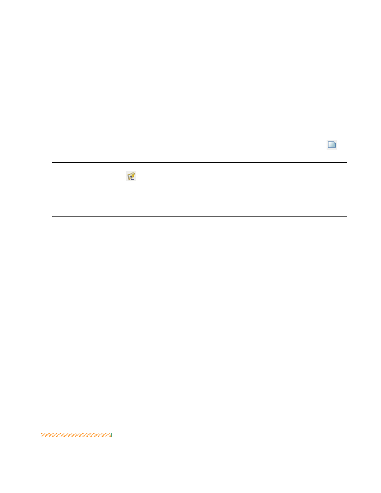
For example, instead of drawing a series of lines to represent a wall in a floor plan view, you can immediately draw a
complete representation of the wall.
By simply switching the drawing view, you can display the same wall in an isometric view.
Overview:Working in Architectural Desktop | 3
Page 10
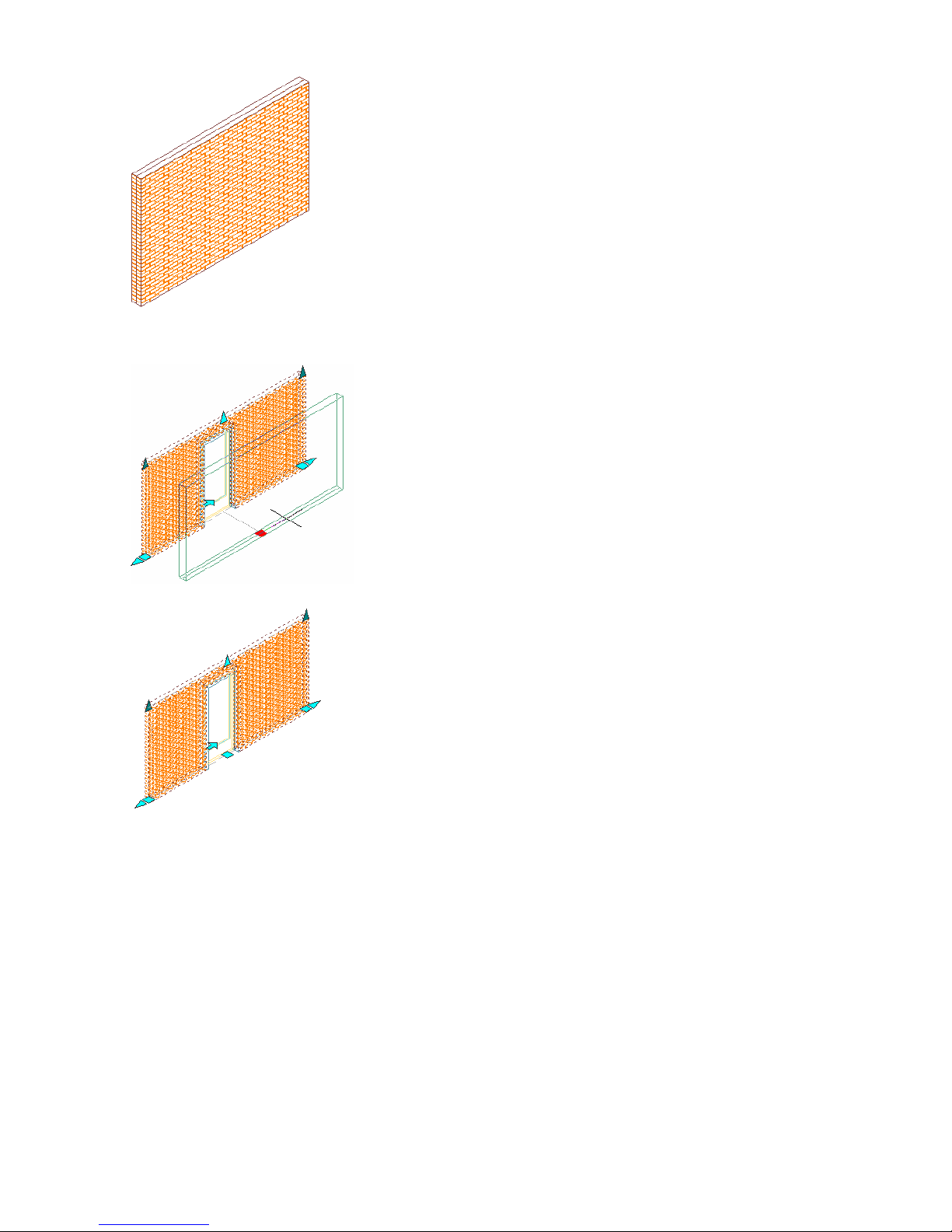
If you add a door to the wall and then move the wall, the door will automatically move with the wall.
If you view the wall with the door in the previous plan view, the change in location that you made in the isometric
view is automatically updated in the plan view.
Because Architectural Desktop contains these ''intelligent'' objects, it supports a drawing-based building information
modeling workflow. In this workflow, you use these objects to design a 3D building model that represents the building
design.
To create a building model, you first create the building geometry in multiple drawings (DWGs), based on its location
in the building model. The individual drawings are referenced together using enhanced AutoCAD® external reference
(xref) technology to assemble the 3D building model. The 3D model not only represents the physical building, but also
stores information about the building and its components. When you have developed the building model enough to
begin documenting it, you can extract drawings, such as elevations and sections, from the building model and reference
them onto plotting sheets.
The benefit of this object-based design approach is that views and data are easily extracted and can remain linked to
the 3D building model. You can extract views, add them to plotting sheets to create a set of construction documents,
and then update the sheets if a change in the building design occurs. Because Architectural Desktop is AutoCAD-based,
you have the flexibility to work in a more traditional 2D drafting environment if you prefer, but it is recommended
that you use the building information modeling approach to derive the most benefit from using Architectural Desktop.
4 | Chapter 1 Introduction
Page 11
At any point in your design workflow, you can use VIZ Render, a separate three-dimensional visualization application
that is included with Architectural Desktop. You can export your Architectural Desktop design to VIZ Render, where
you can create a variety of compelling presentations and design studies, including renderings, animated walkthroughs,
and interactive panoramic renderings.
The next few topics in this overview describe some of the important concepts of working with Architectural Desktop.
Designing with Objects
Before you begin a project, it is helpful to understand some of the main features in Autodesk® Architectural Desktop
that allow you to work with the architectural objects included in the application. The following example demonstrates
how to draw a wall that includes a door.
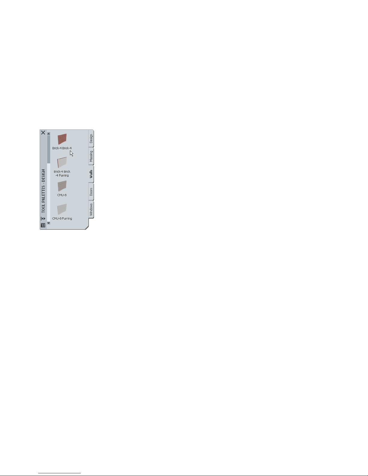
To draw the wall, you select a wall tool from a tool palette.
A wall tool on a tool palette
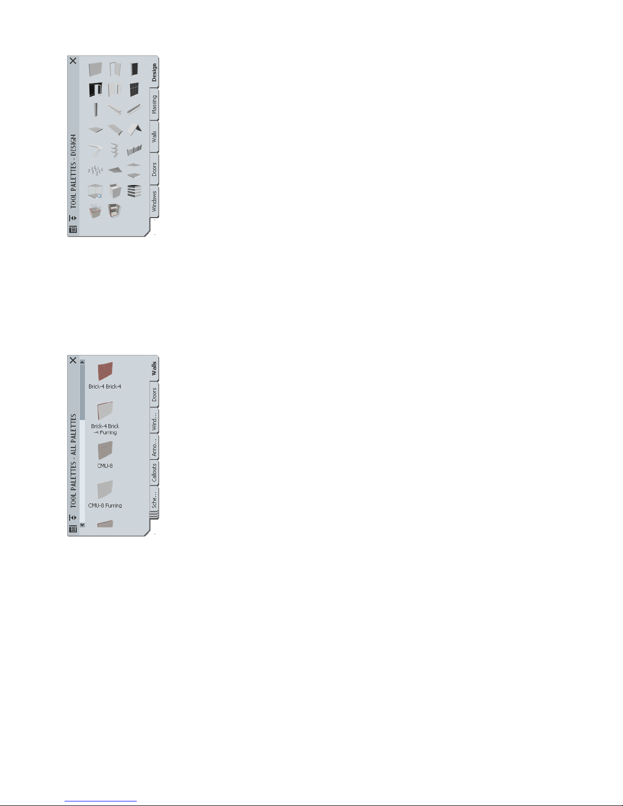
Tools are commands that you use to draw objects. Tools take the form of icons on tabbed panels called palettes. The
tool image represents the real-world object that you want to draw. Tool palettes are organized within tool palette groups,
which contain tools that support a specific work task. The wall tool used in this example is from the Walls tool palette
within the Design tool palette group.
Overview:Working in Architectural Desktop | 5
Page 12
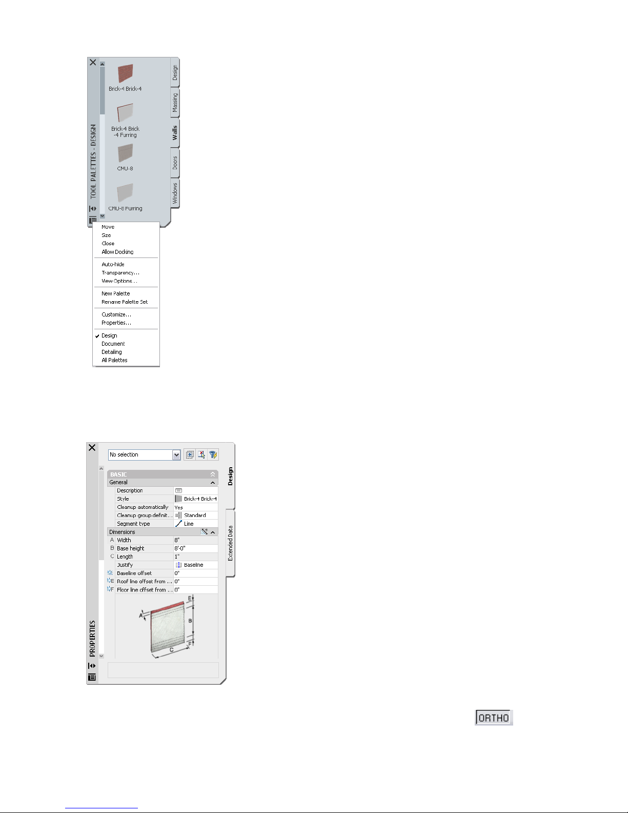
The wall tools on the Walls tool palette in the Design tool palette group
Before you begin to draw the wall, the properties of the wall are displayed in another palette below the Tool palette,
called the Properties palette. You can change some of these properties, such as the width or base height of the wall,
before you draw the wall.
The Properties Palette
Before you specify the start point of the wall, you can use the drawing aids on the application status bar to help you
control how the wall is drawn. To draw this short straight wall segment, you want to click to constrain your
cursor to move only in a horizontal or vertical (orthogonal) direction after you specify the start point.
6 | Chapter 1 Introduction
Page 13
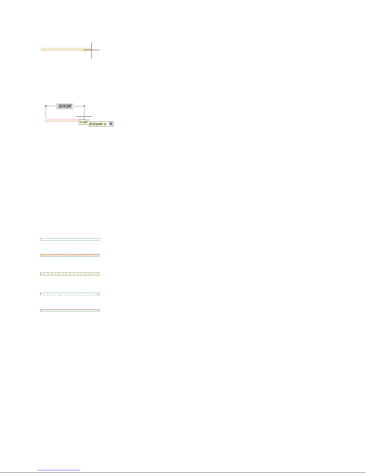
Next, as you move your cursor to specify the length of the wall, the value in the Length field in the Properties palette
changes. When the length field reports the desired length of the wall, you can specify the wall endpoint in the drawing.
Alternatively, you can click the dynamic input option (DYN) on the application status bar to use a direct entry method
to specify the endpoint of the wall. This option provides a field that you can use to enter the desired length of the wall,
instead of specifying a point in the drawing. The angle of the wall is also reported in a separate field as you move the
cursor. You can press TAB to toggle between the two fields.
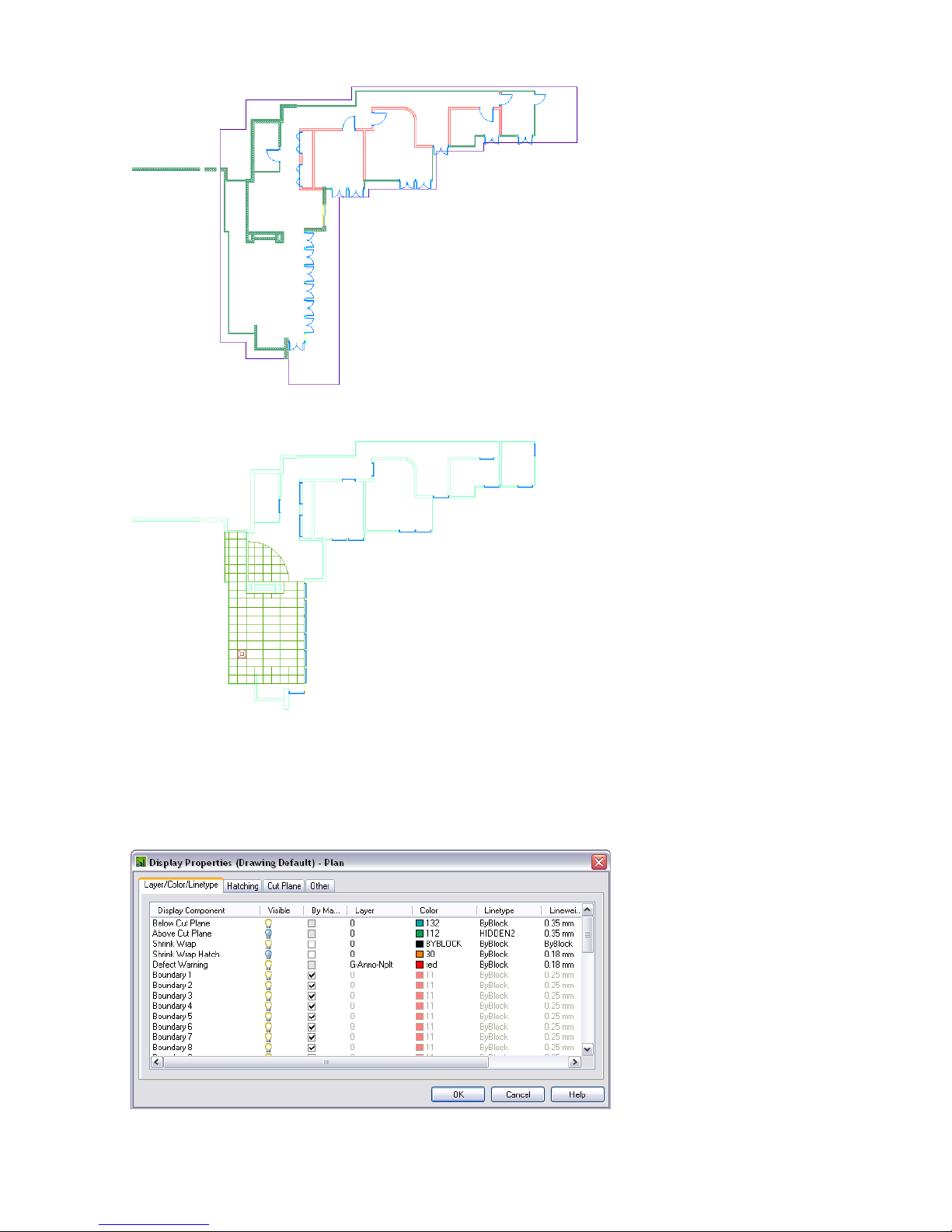
A number of features work together to represent the completed wall in your drawing: the layer, style, and display
settings that are assigned to the wall.
The wall is automatically drawn on a named layer with predefined settings such as color, linetype, and lineweight.
When you draw an object, a layer key style associated with the drawing matches the object to a defined layer in a
process called layer keying. The layer name and settings are determined by a layer standard that is associated with the
layer key style and the drawing. The wall is drawn on layer A-Wall, a layer which conforms to the AIA (American
Institute of Architects) layer standard, but you can use any of the international and professional standards that are
included in Architectural Desktop. You can also create your own office layer standard.
The style of the wall determines what type of wall is being drawn. A style is a set of parameters that you apply to an
object to determine its appearance or function. For walls, styles contain components, which are the materials used to
construct the wall, such as brick, CMU, concrete, studs, air gaps, and insulation. They also can contain wall modifiers,
which change the shape or surface of a wall component.
Walls with different styles
Other object styles contain different parameters. For example, a door style determines the shape (rectangular, arch,
half-round, and so on) and type (number of panels and opening method) of the door. In most cases, the image of the
tool that you select to draw an object represents its style.
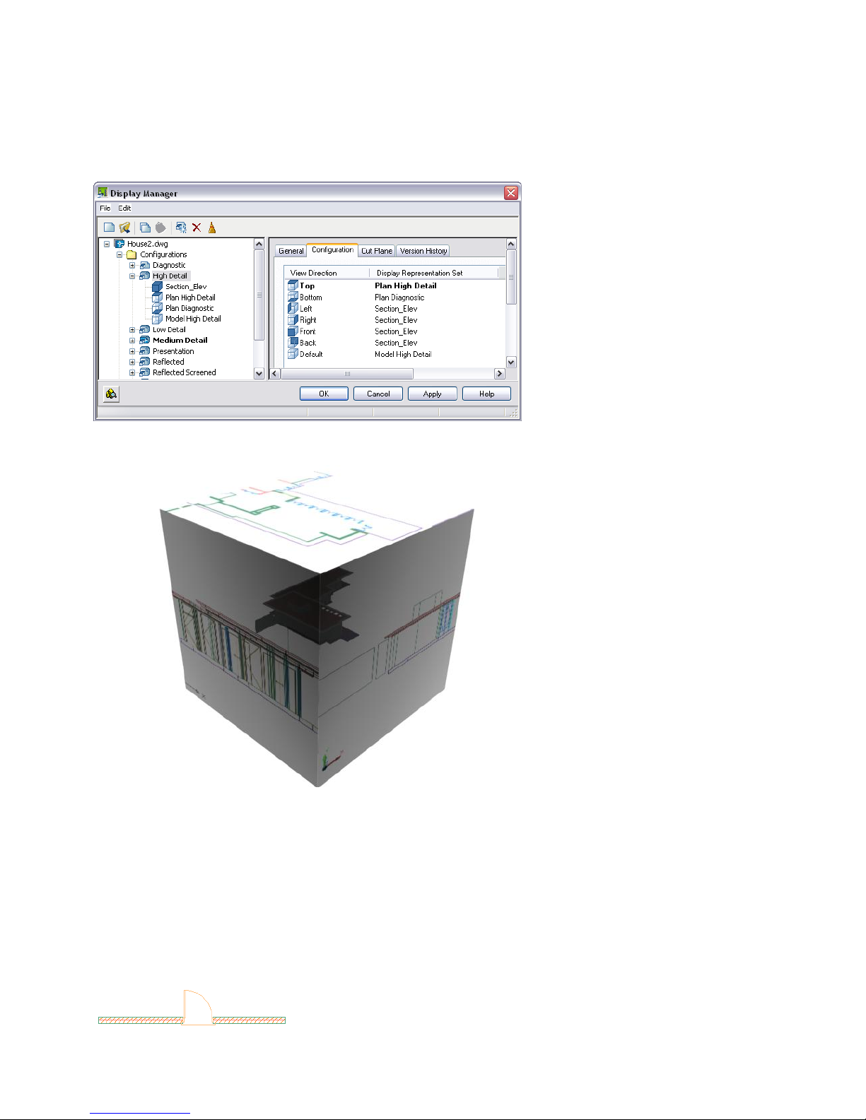
Finally, how you view the drawing in the drawing area helps to determine how the wall looks. A display system works
behind the scenes in Architectural Desktop to control how objects in your drawings are represented. Each object has
a number of display representations, or different ways they can be shown, depending on the type of drawing in which
you need to use them. These display representations control the look of the object geometry as appropriate for different
drawing types, such as high detail plans or reflected ceiling plans. You create objects one at a time in the drawing area,
but you can change how they are represented, which allows you to manage plan views in low, medium, or high detail,
or create reflected ceiling plans - all from the same geometry.
Overview:Working in Architectural Desktop | 7
Page 14
High Detail display representation of a house
Reflected display representation of the same house
Most objects are made up of individual display components within a display representation. The properties of each
component, such as visibility, layer, linetype, and lineweight, can be configured in the display representation to change
how the object displays in a drawing.
Display components in the Plan display representation of a wall
8 | Chapter 1 Introduction
Page 15
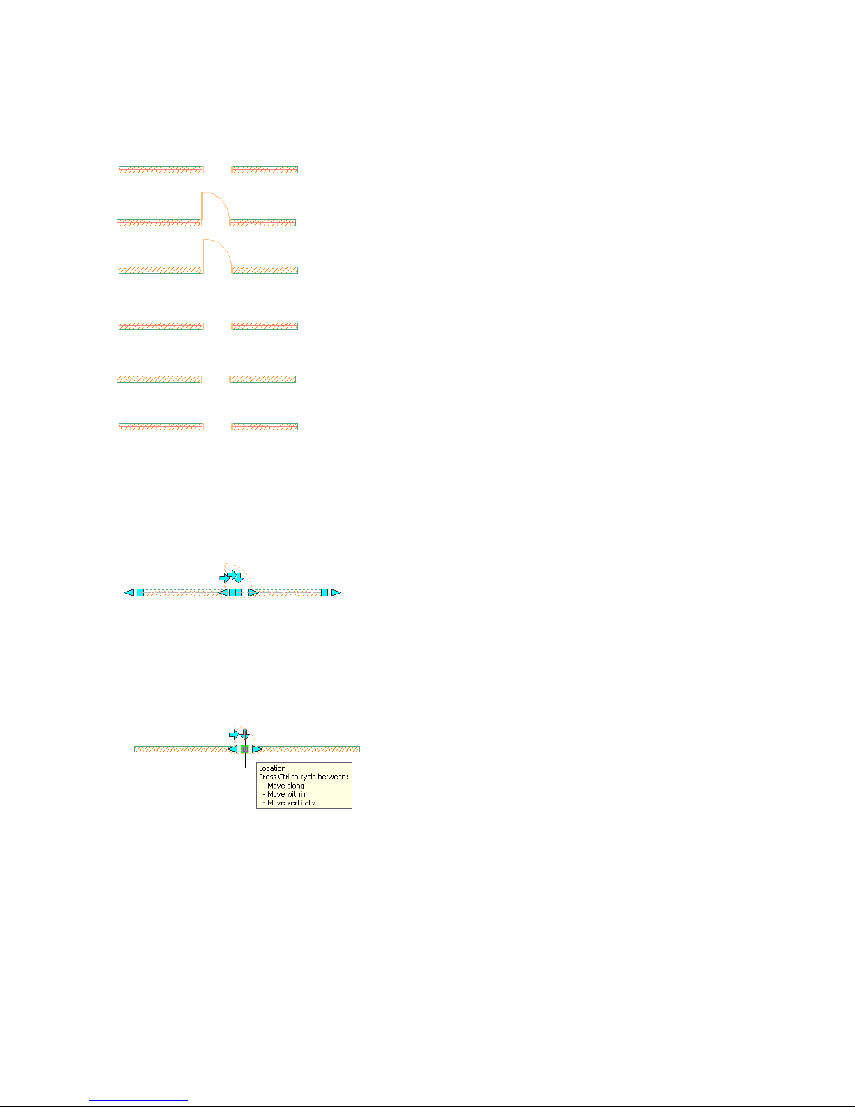
Different object display representations are grouped in display sets. Display sets group display representations according
to the type of view the objects need to display in. For example, the Plan display set includes the Plan display
representations of walls, curtain walls, doors, stairs, railings, and roofs. Display sets are then assigned to view directions
in display configurations, which can be changed for the drawing area and can be attached to viewports in a sheet
layout. By changing the display configuration and/or view direction in a viewport, objects in that viewport can display
differently, you can ''represent'' the same objects multiple ways for use in different types of drawings.
A display configuration has representation sets assigned to view direction
The drawing is a volume (cube) with representation sets assigned to the viewing direction.
Drawing templates provided with Architectural Desktop contain display settings that you use to easily manage the
display of objects in your drawings created from these templates. They also associate particular layer standards and
layer key styles to drawings. Object styles are not included in the templates, but stored and managed in one or more
external drawings.
Next, you want to add a door to the example wall. You select a door tool, and select the wall. You can adjust any of
the properties of the door in the Properties palette before you select the wall a second time to place the door in the
wall. Simply moving the cursor to either side of the wall before you place the door flips the door swing from one face
of the wall to the other.
A door placed in a wall
Overview:Working in Architectural Desktop | 9
Page 16
You can edit or change the style of either the wall or door to change its appearance. Object styles are the main way to
differentiate between building components. You would have, in a project, multiple styles for objects such as walls,
doors, and windows. Editing any door or wall style in the current drawing will change all doors or walls of the same
style. In addition to the ability to edit a style you can change object display settings for a single object (such as the
wall) or for all the walls with the same style.
Display components turned off in an individual door representation
Display components turned off in a door style
You can change the properties of the individual wall or door, such as overall dimensions, by double-clicking them and
changing the properties in the Properties palette, or by selecting them and grip-editing them onscreen. When you
select and move a dimension grip, dynamic dimensions are displayed, allowing you to precisely move the grip. The
door also has grips that enable you to flip the door swing to the other face of the wall or reverse its direction.
Grip-editing a wall and door
If you move your cursor over a grip, a grip tip displays the name and function and function of the grip. Often the grip
tip lists editing options.
A door grip tip
Moving the wall with its location grip will also move the door. This inter-relationship between objects is what allows
you to create 3D building models or drawings with a minimum of editing. You do not have individual linework requiring
extensive editing; instead, you have associated objects.
In the next section, you learn how to create a building project. Within the project, you create a building model and
extract information from it to create construction documentation. For more information on the concepts and features
in this section, see the online Architectural Desktop User’s Guide.
Completing a Project
After you have created a conceptual study and have understood the design requirements of a building project, you
have a good idea of your building design. You know the basic structure of the building, and how many floors or
10 | Chapter 1 Introduction
Page 17
divisions, such as wings or phased expansions, it has. You can also identify the major components of the building. You
may have schematic drawings or drawings from a previous project that you want to use to create parts of the building
design. At this point, you are ready to start a project in Autodesk® Architectural Desktop.
A project in Architectural Desktop is not just a job name or number; it stores, organizes, and manages the drawings
that make up both your building model and the plotting sheets. Within the project, drawings that contain the building
model geometry are referenced together, and then views of the building model are referenced onto plotting sheets.
When you create a project, you can specify the project information, including the project name, number, description,
and the templates that contain the layouts, styles, and display settings for different types of drawings in your project.
You can also designate project-specific tool palettes that contain tools tailored for the building in the project.
The project file structure is created when you create a project. There is no need to set up a file structure for the project
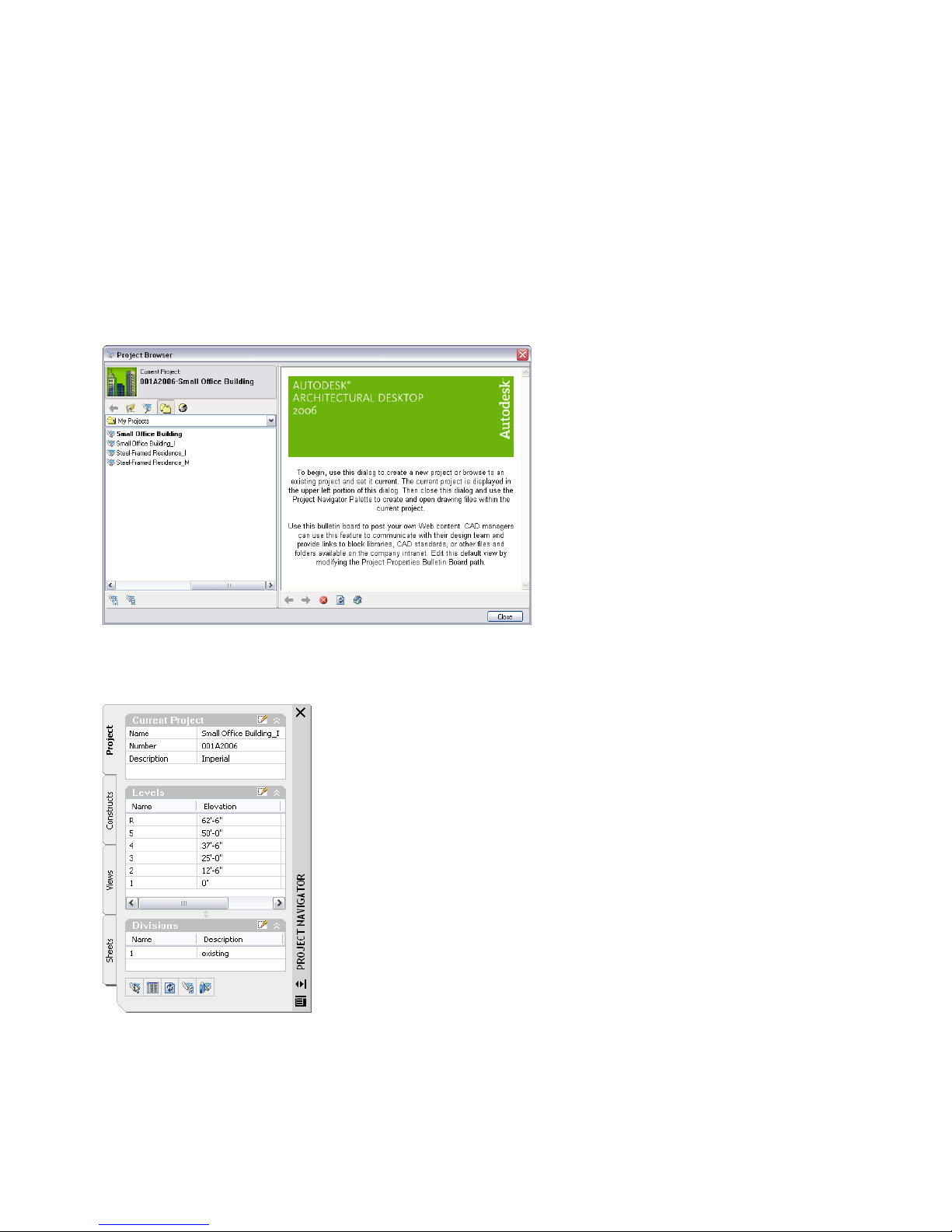
in Windows Explorer. Two UI elements within Architectural Desktop, the Project Browser and the Project Navigator
palette, provide access to your projects and the drawings organized within them. The Project Browser lets you create,
set up, and switch between projects.
The Project Browser
The Project Navigator palette provides the context in which you create, edit, and manage all of your project drawings.
The Project Navigator palette
The project structure contains a main project folder with a number of sub-folders to organize the different types of
drawings that the project will contain. Drawings are classified within the project as constructs, elements, views, and
sheets.
Two types of drawings, constructs and elements, contain the geometry that is referenced together to create the building
model. Both drawing types are DWG files; there is no difference in file type or format. The only difference between
them is the way that they are used and how they are referenced to create the building model.
Overview:Working in Architectural Desktop | 11
Page 18
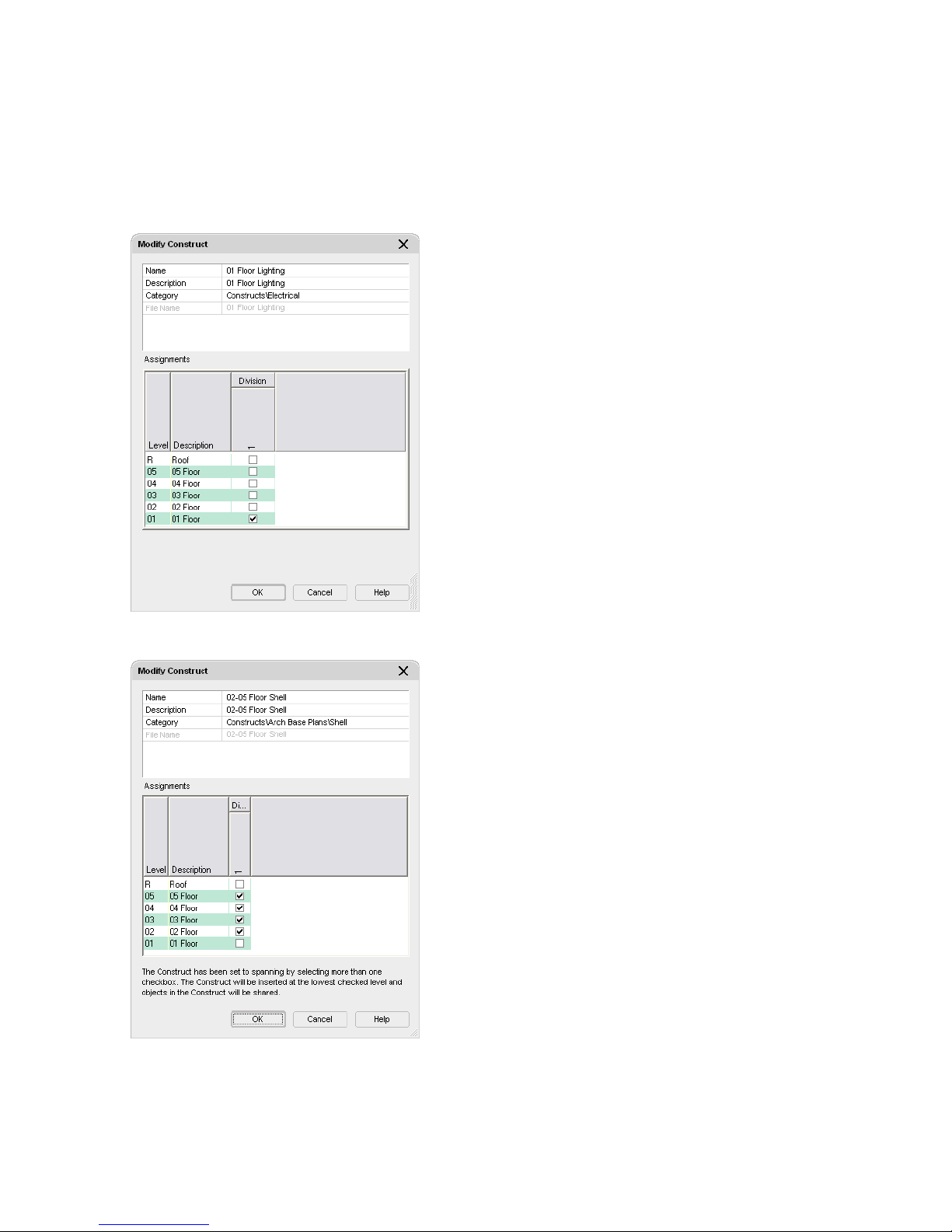
Constructs are the main building blocks of the model. They define unique portions of the building and are assigned
to a location (level and division) within the building. For example, assume an existing commercial building with
multiple floors and one division (the existing building or main division). The first floor of the building could consist
of an exterior shell construct, a first-floor construct with lighting, and a first-floor interior partitions construct. Each
of these constructs would be assigned to the first level and the main division of the project. The exterior shell construct,
drawn to the full height of the building, would be assigned to all levels of the project, making it span the height of the
building. This type of construct is called a spanning construct. The construct’s level and division assignments define
its exact location in the building model.
A lighting construct assigned to its location in the building
A spanning construct drawn to span several floors and assigned to the floors (levels)
Elements are collections of geometry that can be referenced repeatedly within multiple constructs. You could apply a
typical service core element that includes restrooms to constructs assigned to multiple floors. You would draft the core
once as an element, but it would report as separate items (doors, walls, and so on), because the items are referenced to
separate constructs. If you tag each service core door, the doors would report as individual items in a schedule.
12 | Chapter 1 Introduction
Page 19
When you set up the basic levels and divisions of a building model, you create a matrix of locations where you can
assign the building geometry that will create your building model. By default, a project has one level (that has an
elevation of 0 and represents the ground floor) and one division.
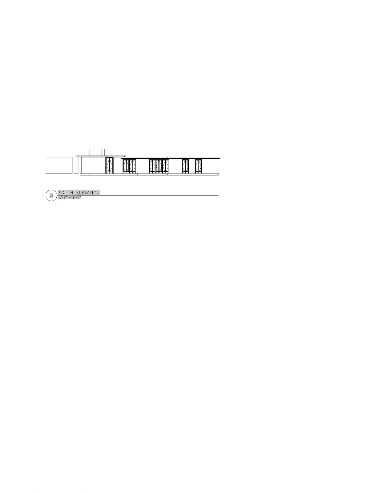
When you have developed the building model enough to begin documenting it, you reference views of the building
model onto plotting sheets. A view drawing references a number of constructs according to their location in the building
to present a specific view of the building model. To create a view drawing, you decide what part of the building model
you wish to look at and the type of view to generate. You could, for example, create a first-floor reflected ceiling plan
or a second-floor framing plan. You could also create a composite view of all floors in the building.
You can create three different types of views within projects: general views, detail views, and section/elevation views.
General views reference constructs to create specific views of the building model. Detail and section/elevation views
contain one or more model space views that display a defined portion of the drawing. A model space view is a portion
of the view drawing that may be displayed in its own viewport on a layout tab of a drawing. You can automatically
create Detail and Section/Elevation views with callouts. The resulting named model space views can subsequently be
annotated and placed on sheets.
A model space view for an automatically created house elevation, placed on a sheet
Sheet drawings are the DWG files that you plot or electronically publish to produce construction documents. Sheet
drawings contain sheets, which are paper space layouts that provide the layout of the sheet. You reference model space
views from view drawings onto sheets to create sheet views. Any changes that you make to the model can be updated
in the sheets because the building model drawings are referenced into the views on the sheets.
You can add annotation like tags, dimensions, and schedule tables to a sheet, or you can add it in a view that you
reference onto a sheet. Whether to create the annotation in a view or on a sheet is a decision you make based on your
workflow and individual needs.
Each project contains a single sheet set, which is a named and ordered collection of all the sheets in the project. The
project sheet set represents the project documentation. You can plot the sheets or electronically publish the sheet set
to a DWF (Design Web Format) file that can be viewed by anyone using Autodesk® DWF Viewer or Autodesk® DWF
Composer.
To establish, maintain and synchronize standards across all the different types of drawings in an Architectural Desktop
project, you can set up project standards. The Project Standards feature lets you set standard styles, display settings,
and AutoCAD standards that you want to use in all your project drawings. Standard styles and display settings are
specified in one or more standards drawings that you associate with the project. You can then synchronize your project
drawings with these standards throughout the project lifecycle, either automatically, or on demand.
Integrating VIZ Render in Your Project Workflow
VIZ Render is a separate three-dimensional visualization application that is installed with Autodesk® Architectural
Desktop. You can export your Architectural Desktop designs to VIZ Render, where you can create a variety of compelling
presentations and design studies, including renderings, animated walkthroughs, and interactive panoramic renderings.
These studies are separate from your project drawings; they are not part of the current project.
When your design is at a point where you want to use VIZ Render to study or present it, you use the following workflow:
First, you export the geometry and materials that comprise your Architectural Desktop design to VIZ Render using a
file linking command in Architectural Desktop.
Overview:Working in Architectural Desktop | 13
Page 20
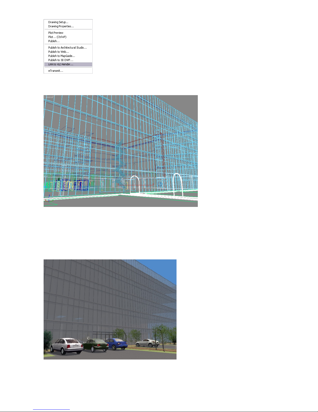
After you click the link, VIZ Render is opened automatically, and the geometry and materials that comprise your current
Architectural Desktop model are displayed in VIZ Render in a DRF file.
A live data link between the current Architectural Desktop drawing and the VIZ Render DRF is established. This link
will load any changes in the geometry or material of the Architectural Desktop model into VIZ Render for as long as
you retain the file link.
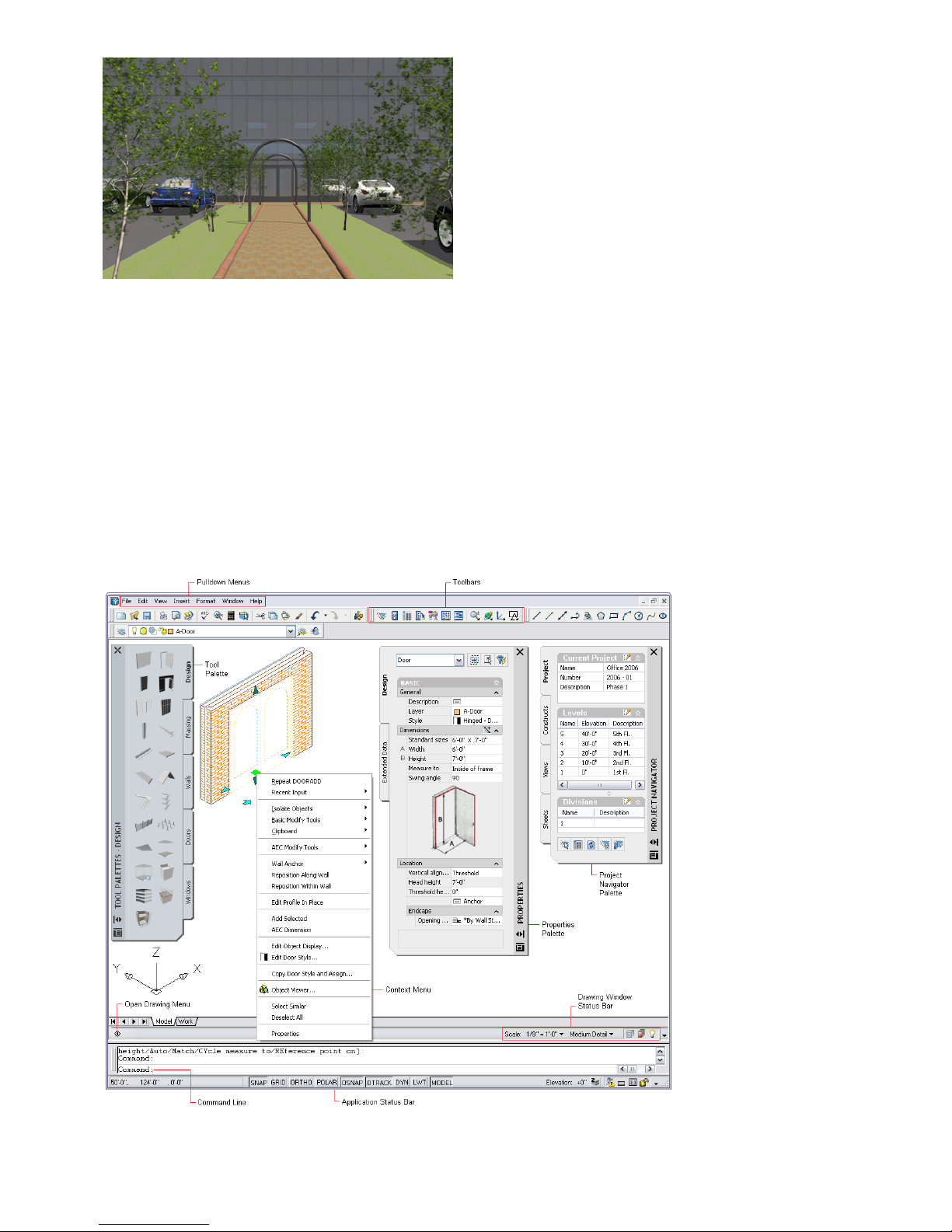
Next, depending on the type of visualization you want to create with VIZ Render, you can make changes and additions
to the design in VIZ Render. Although you cannot model in VIZ Render, you can rearrange objects, modify their
materials, and add lighting, cameras, and additional objects (like the cars and trees in the renderings below) to create
a realistic environment for your design.
14 | Chapter 1 Introduction
Page 21
After you create an image or animation in VIZ Render, you may find that you need to make a change to the design
geometry or material in Architectural Desktop. You can go back to Architectural Desktop, make the change, and use
the live file link to load the changes in VIZ Render.
To learn more about VIZ Render, see the VIZ Render Help and Tutorials, accessible from the VIZ Render Help menu.
Understanding the User Interface
Autodesk® Architectural Desktop includes two distinct user interfaces: the workspace and the VIZ Render user interface.
The workspace is displayed when you start Architectural Desktop. The workspace and its components support you
through your project workflow, allowing you to move seamlessly from creating a project and designing a building
model to producing construction documents.
The Autodesk Architectural Desktop workspace
Understanding the User Interface | 15
Page 22
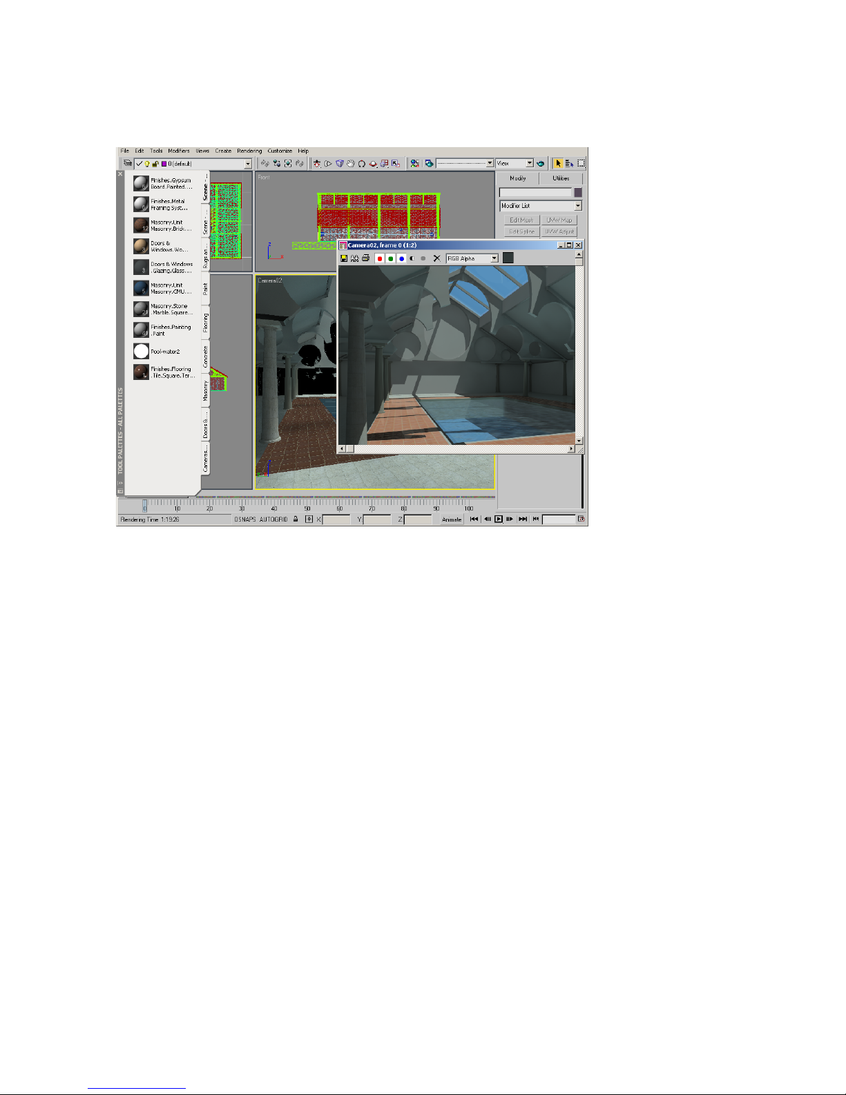
VIZ Render, the separate 3D visualization application that is included with Architectural Desktop, has its own user
interface that you can use to produce photo-realistic images and animations of your building designs. The VIZ Render
user interface is displayed when you export an Architectural Desktop design to VIZ Render, or when you start VIZ
Render from the VIZ Render icon on your desktop.
The VIZ Render user interface
The topics in this section describe the workspace and its components. To learn about the VIZ Render user interface,
see the VIZ Render Help and Tutorials, accessible from the VIZ Render Help menu.
The Workspace
Before you begin the tutorial, it is helpful to understand the workspace and some of its main components. Use the
illustration below to familiarize yourself with the workspace and its components, and then review the following topics.
16 | Chapter 1 Introduction
Page 23
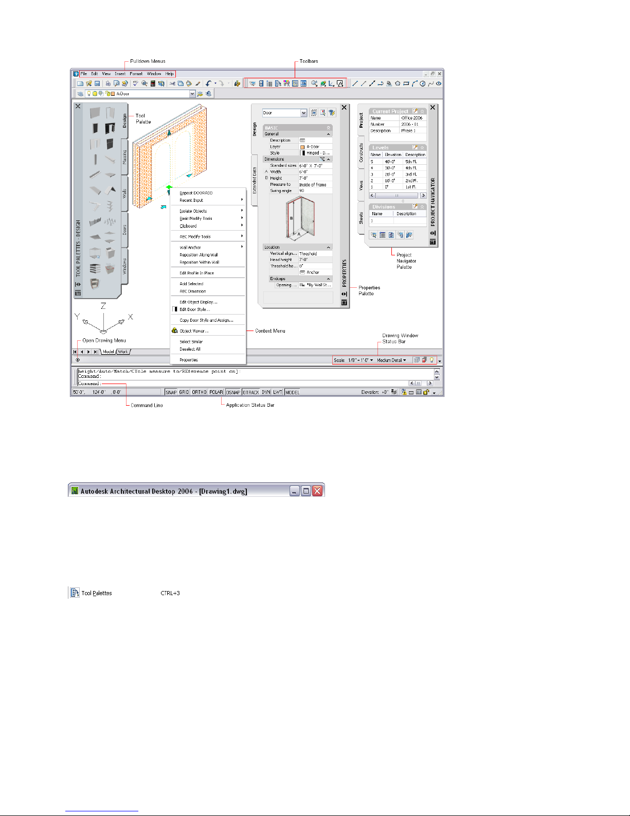
The Autodesk Architectural Desktop workspace
Title Bar
The title bar is located at the top of your drawing window. The product name, product version, and current drawing
name are displayed in the title bar. Standard Microsoft® Windows buttons allow you to minimize and resize the
workspace, as well as close Autodesk® Architectural Desktop.
Menu Bar
The menu bar contains six default pulldown menus that are organized according to your workflow: File, Edit, View,
Insert, Format, Window, and Help.
Many of the workspace components are accessed from these menus. Where applicable, the menus show alternate ways
of accessing a command, such as a toolbar button or a shortcut key.
Additional pulldown menus
You can load and use four additional pulldown menus: Design, Documentation, CAD Manager, and 3D Solids.
The Design and Documentation menus are similar to those included in releases prior to Autodesk® Architectural Desktop
2004, in that they include design and documentation object commands. Use these menus as an alternative to accessing
object commands from tools.
The CAD Manager menu provides access to advanced features like the VBA Editor, the LISP Editor, Project Standards,
the Keynote Editor, and Tool Catalog Generator.
The 3D Solids menu provides access to the AutoCAD 3D Solids objects and commands. In Architectural Desktop, 3D
solids can be converted to mass elements with material assignments that can be used in production drafting. The 3D
Solids menu helps AutoCAD users make the most of their 3D drafting skills.
Understanding the User Interface | 17
Page 24
To load the additional menus, on the Window menu, click Pulldowns, and click the menu you want to load. After you
load these menus, you can display the equivalent Design, Documentation, CAD Manager, and Solids toolbars.
Toolbars
Toolbars, located directly under the menu bar, contain groups of commands that you access frequently in a drawing
session. Objects are not accessed from the toolbars, as they are primarily accessed from tool palettes.
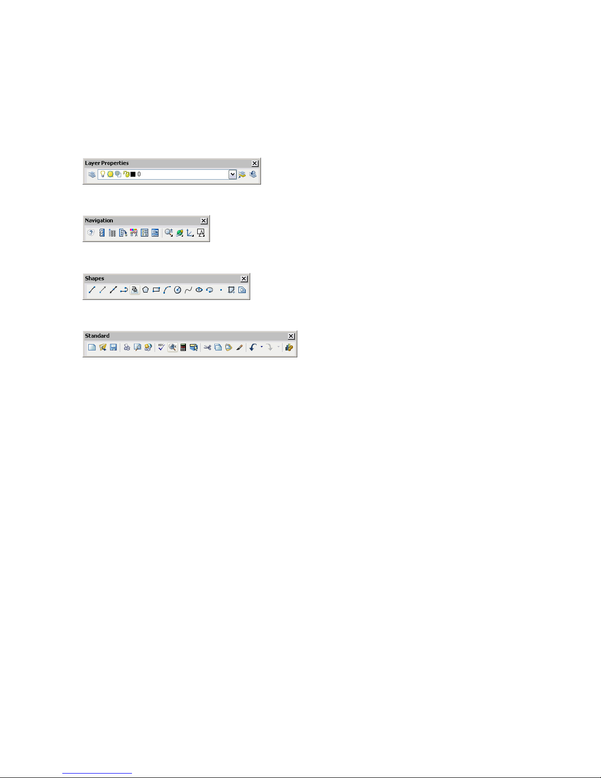
Four toolbars are displayed by default: Standard, Navigation, Layer Properties, and Shapes. Many of the user interface
components described in this section are located on the Navigation toolbar.
Layer Properties toolbar: layer commands, layer list, and Layer Manager command
Navigation toolbar: utility, zoom, view, UCS, and shading commands
Shapes toolbar: 2D object commands, such as lines, arcs, polylines, splines
Standard toolbar: drawing, copy, paste, undo, and regenerate model commands
To display additional toolbars, right-click in the toolbar area (not on a toolbar), and click ADT. A menu lists the toolbars
that you can click to display. If you load the 3D Solids, CAD Manager, Design, and Documentation pulldown menus,
you can display the equivalent toolbars.
Drawing Window and Layout Tabs
The drawing window is where you design and document your building models. The drawing window contains layouts,
that you can switch between by clicking the layout tabs at the bottom of the drawing window.
Context Menus
A context menu contains commands that are relevant to an object that is currently selected, providing you a convenient
way to edit the objects that you draw. To display a context menu, select an object, and right-click.
18 | Chapter 1 Introduction
Page 25
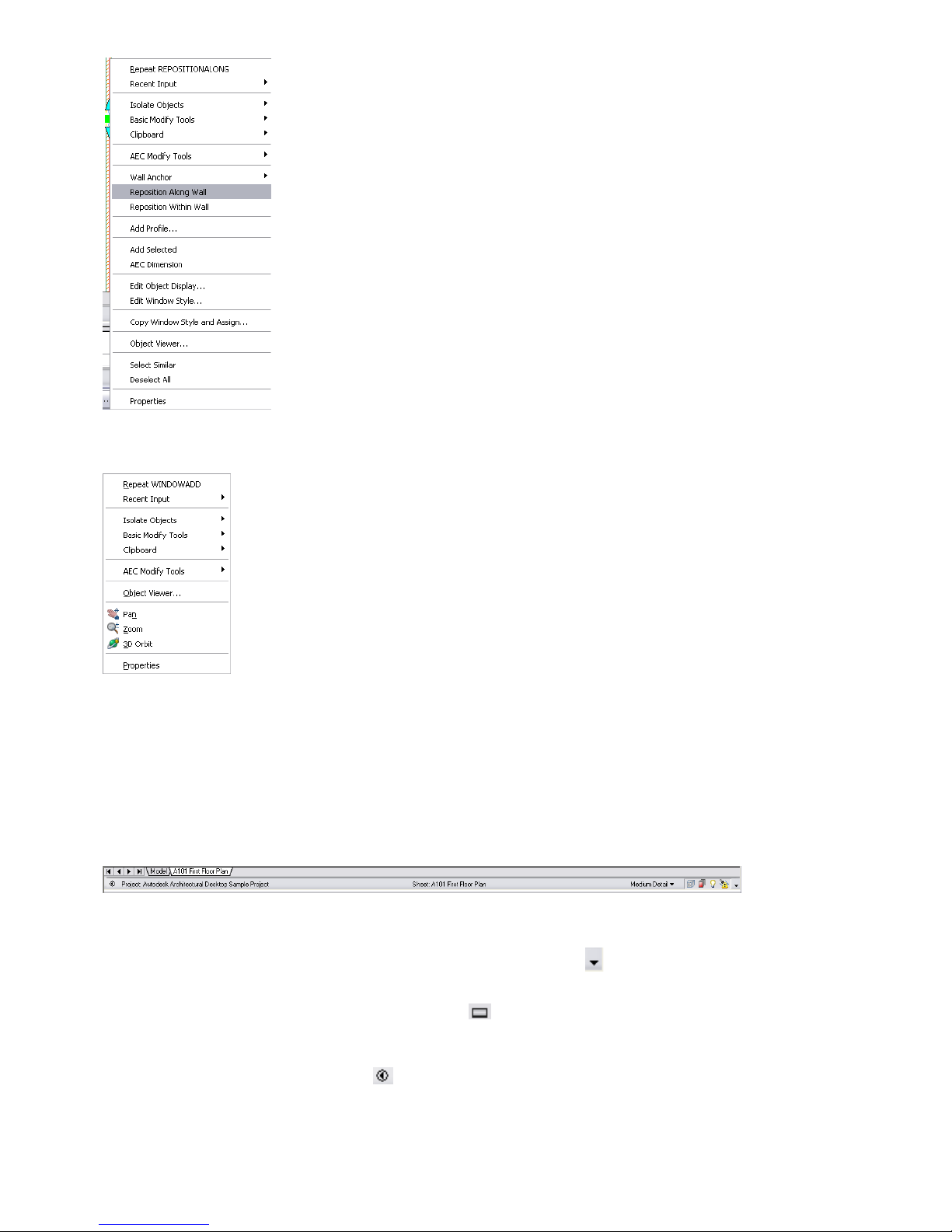
A general context menu is also available when you right-click in the drawing area without selecting an object. This
menu contains all modify tools, viewing commands, and the Properties command.
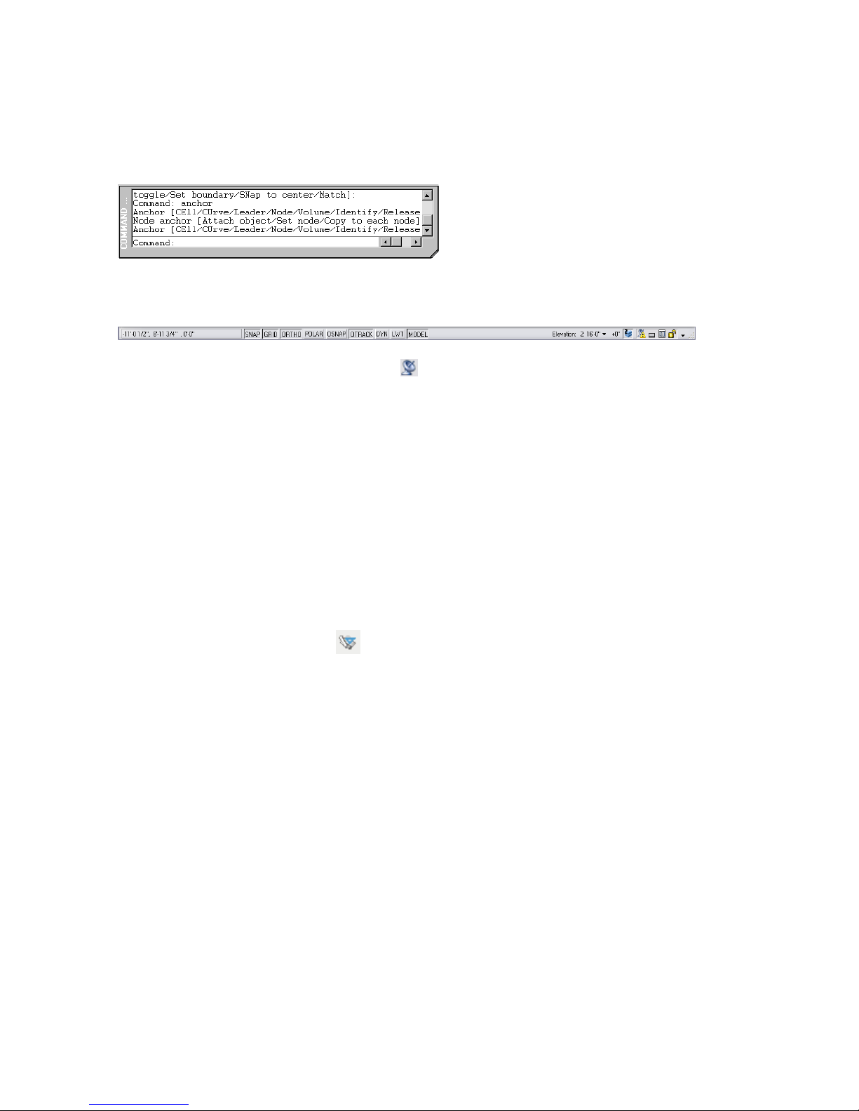
Drawing Window Status Bar
The drawing window status bar is located under the drawing window. It reports the following information about the
current project and drawing:
■ the name of the current project
■ the type (construct, element, view, or sheet) and name of the current drawing
■ the active scale for the current drawing or viewport
■ the display configuration of the current viewport or model space view
Options at the far right of the drawing window status bar provide access to the Surface Hatch Toggle, Layer Key overrides,
the Isolate Objects command that hides and displays objects that you select, and access to AEC Project Standards. To
display and clear these options from the drawing window status bar, click , and click the options that you want to
display or clear.
To display and hide the drawing window status bar, click on the application status bar at the bottom of your screen.
Open Drawing Menu
To display the Open Drawing menu, click on the drawing window status bar. A menu displays a number of drawing
setup, plotting, and publishing commands. You can use the Drawing Setup command to change settings of your current
drawing, such as the active scale, layer standard, and layer key style. Also included is the Link to VIZ Render command
that you use to export building model geometry and materials from Architectural Desktop to VIZ Render.
Understanding the User Interface | 19
Page 26
Command Palette
The command palette is located under the drawing window. If you prefer, you can enter all Architectural Desktop
commands directly on the command line, including those used by the tools.
To display a list of Architectural Desktop commands:
■ On the command palette, enter arx.
■ Enter c.
Application Status Bar
The application status bar is located under the command palette and contains a number of drawing aids.
You can also access the Communication Center , an in-product notification system that keeps you up to date on
service pack availability and provides information for Autodesk® Subscription Program members. When new updates
are available, the Communication Center icon displays with a yellow exclamation mark.
The Project Browser and Project Navigator Palette
The Project Browser and Project Navigator palette are the two workspace components that you use to create and manage
Architectural Desktop projects. The Project Browser provides you high-level management of your projects: you use it
to create, copy, and switch between projects. After you create or select a project and close the Project Browser, the
Project Navigator palette is displayed automatically. You use it to create, edit, and manage the drawings within the
project.
The Project Browser
To display the Project Browser:
■ On the File menu, click Project Browser.
■ On the Navigation toolbar, click .
■ To configure the Project Browser to display when you start Architectural Desktop, click Format ➤ Options. Click
the AEC Project Defaults tab, and select Show Project Browser at startup.
In the Project Browser, you can create projects, switch from one project to another, and copy projects. You can also:
■ define or change the project settings, including the templates, standards, and tool palettes.
■ specify the detail component and keynote databases that you want project members to use to create details.
■ electronically transmit and archive projects.
The current project is displayed on the top left side of the Project Browser. You can associate a graphic to display next
to the project name. Below the current project, available projects are listed under the project folder location. A Windows
Explorer-like tree allows you to navigate the project directory. The right pane of the Project Browser includes an
embedded Internet Explorer that allows you to link to a web page on an Internet or intranet site. You can use the linked
web page as a bulletin board for communicating project information, such as photographs, meeting times, and issues,
to the project team.
®
20 | Chapter 1 Introduction
Page 27
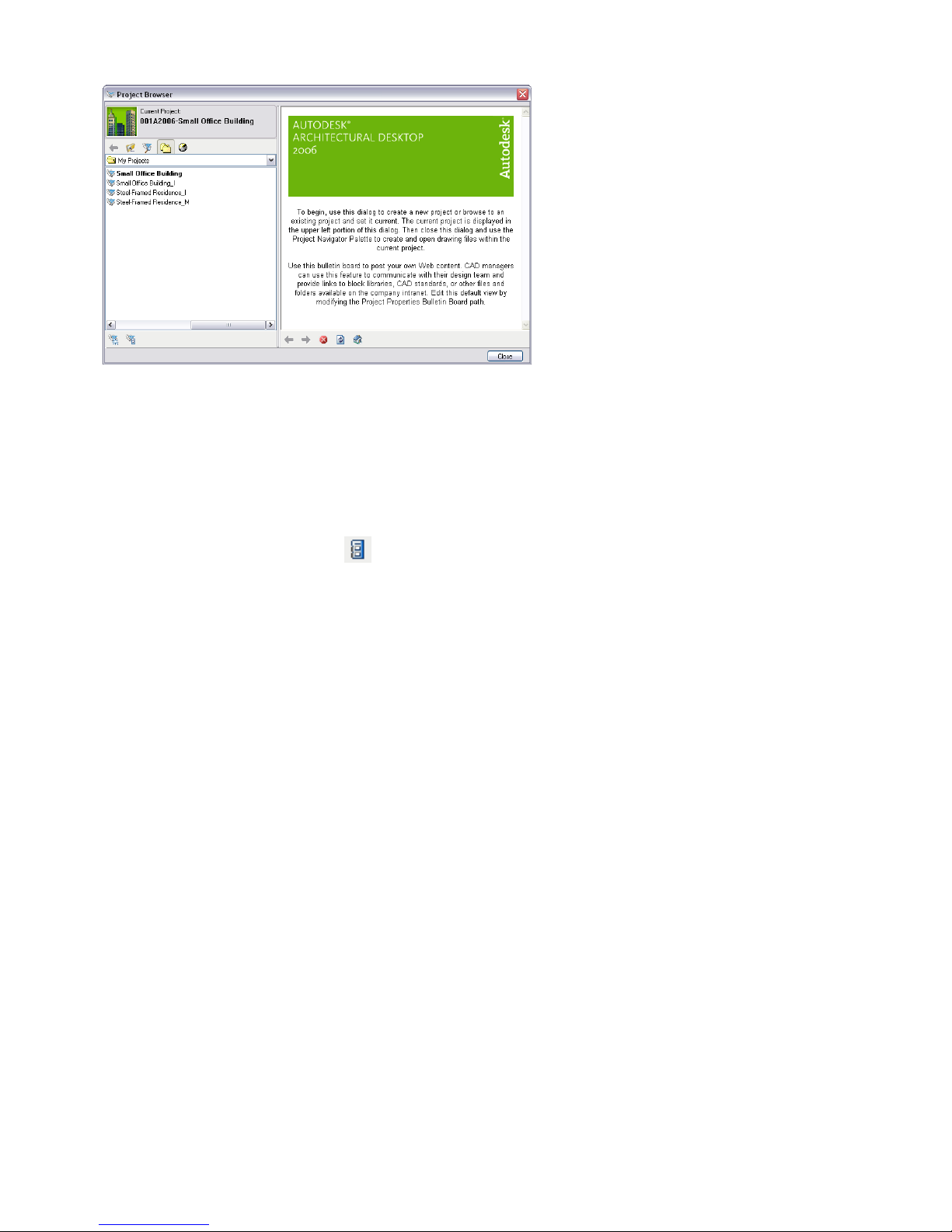
The Project Browser
After you create a new project or set a project current and close the Project Browser, the Project Navigator palette is
displayed.
Project Navigator Palette
To display the Project Navigator palette:
■ Close the Project Browser.
■ On the Window menu, click Project Navigator Palette.
■ On the Navigation toolbar, click .
■ Press CTRL + 5.
The Project Navigator palette is the context in which you create, edit, and display all of your project drawings, including
elements, constructs, views, and sheets. The Project Navigator contains four fixed tabs that correspond to the main
phases of a building project:
■ The Project tab contains the project information, including the levels and divisions in the building model, a Content
Browser icon that will open a project-specific library of tools, and a link to configure project standards.
■ The Constructs tab manages the construct and element drawings that create the building model.
■ The Views tab manages the drawings that contain views of the model that you reference from constructs.
■ The Sheets tab organizes all the plotting sheets that you create from referenced views into a single project sheet
set.
Understanding the User Interface | 21
Page 28
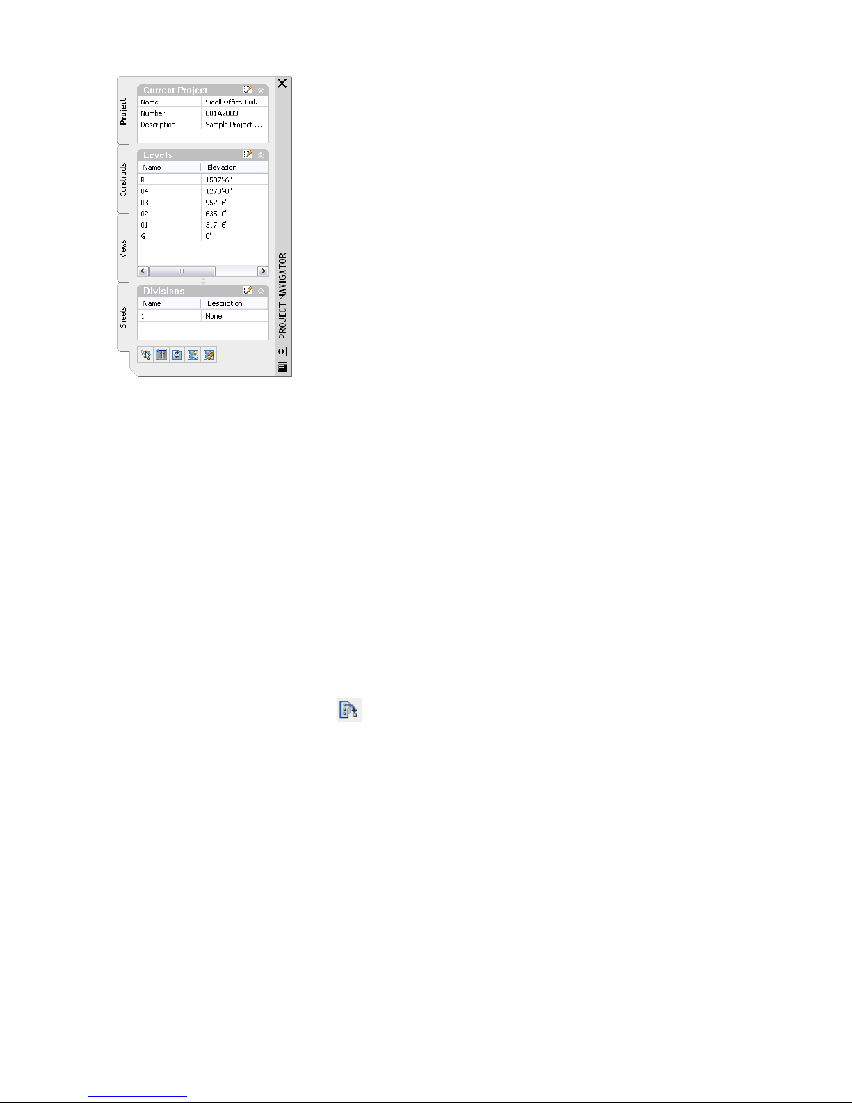
The Project Navigator palette
The Constructs, Views, and Sheets tabs organize the project drawings in a tree view, the Drawing Explorer. You can
organize the drawings in categories within the tabs of the Drawing Explorer and drag the drawings between the categories.
You can also drag elements, constructs, views, and sheets into the drawing area, and drag objects from the drawing
area into an element or construct on the Constructs tab in the Project Navigator.
You can drag drawings from previous projects, AutoCAD drawings, and Autodesk® Building Systems drawings into the
Project Navigator from Windows Explorer to be added to the project as elements, constructs, views, or sheets. This
allows project team members or consultants using AutoCAD or AutoCAD LT® to add their drawings to the project.
The references that create the project drawings, typically of an element to a construct, a construct to a view, and a view
to a sheet, enhance drawing coordination. An update to a construct in a project, such as a floor plan, is automatically
passed along to a view of an annotated floor plan and a sheet containing the scaled view. Notifications of changes are
sent to project team members as the drawings change, so team members can update any of their drawings that reference
the update drawings.
Tools and Tool Palettes
To display the tool palettes set:
■ On the Window menu, click Tool Palettes.
■ On the Navigation tool bar, click .
■ Press CTRL + 3.
One of the first things that you see in the Architectural Desktop workspace is that tools are organized on individual
tool palettes on a larger tool palette, the tool palettes set. Tools represent the individual objects you can add to a drawing.
The tool image is a preview of the tool style. When you add an object with a specific tool, the object is created with
the settings defined in the tool properties.
22 | Chapter 1 Introduction
Page 29
The Design tool palette
Three default tool palette groups - Design, Document, and Detailing - provide instant access to a complete inventory
of Architectural Desktop tools. The three tool palette groups correspond to stages in the architectural design process
and contain palettes that feature relevant tools. For example, the Design palette group contains Design, Massing, Walls,
Doors, and Windows palettes. You might use the Design palette, which features objects with standard styles only, in
your early design stage, and then use tools from the Walls, Doors, and Windows palettes to convert the objects to
specific styles later in the project. To display all the tool palettes from the available tool palette groups, click the title
bar of the tool palettes set, right-click, and click All palettes.
All Design, Document, and Detailing palettes
You can add tool palettes to tool palette groups from a tool catalog in the Content Browser, a utility where you can
store, share, and exchanges tool and tool palettes.You can create custom tool palettes that address your specific design
needs, like a palette that stores commonly used curtain wall, stair, and window tools. Tools can be organized on palettes
with separators and text to structure large palettes.
Understanding the User Interface | 23
Page 30
Tools grouped on a custom palette
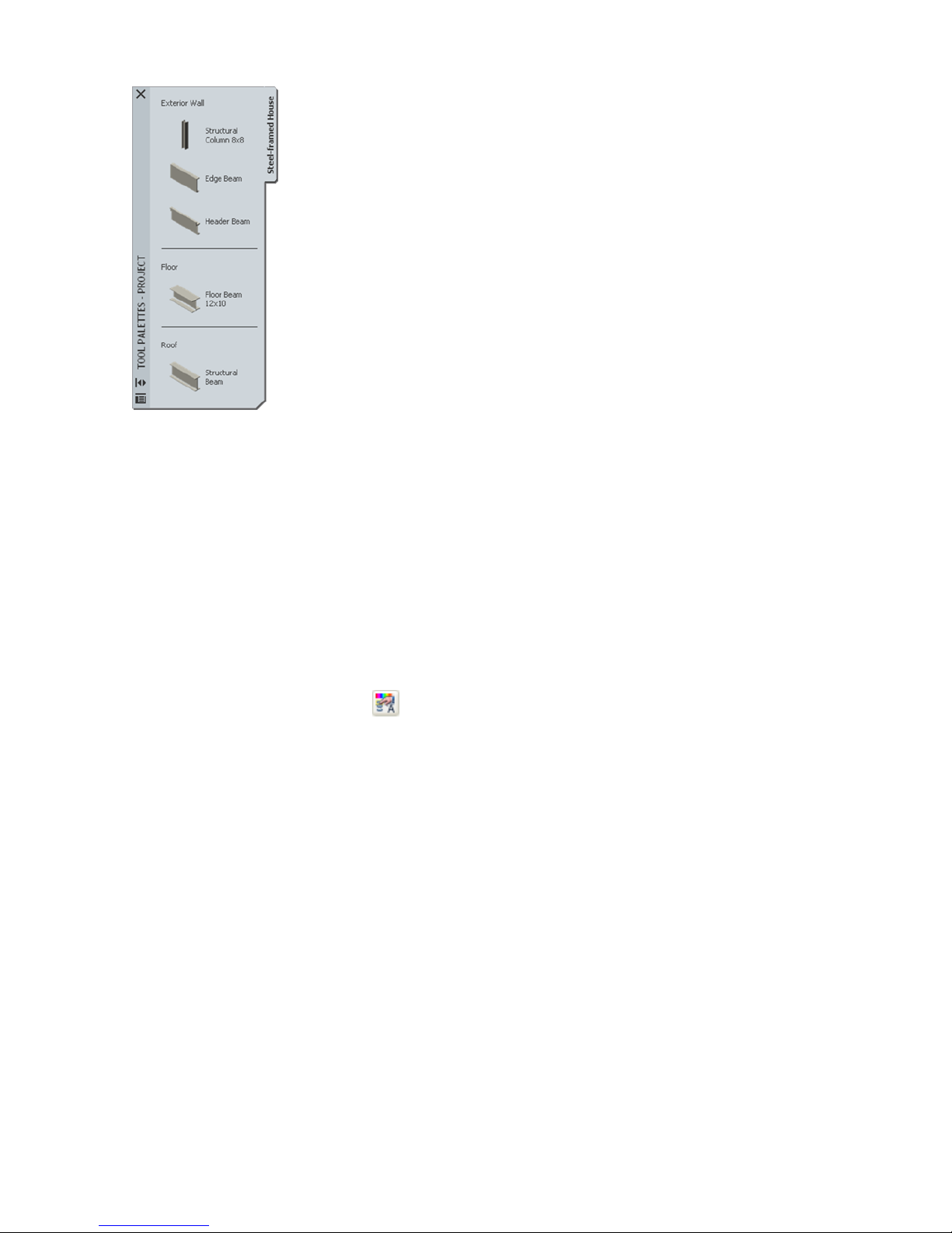
New projects contain project-specific tool palette groups that have the same name as the project in which they are
created. You can create project-specific tools and store them in such a palette group. If you open a project that was
created in an earlier release of Architectural Desktop, no project tool palette group is displayed.
You can create projects according to building type, such as residential, commercial, or educational, and then use these
projects as templates to create other projects. Creating projects from these template projects lets you create projects
that have custom tools, palettes, and content ready for use at the inception of a new project.
The Properties Palette
To display the Properties palette:
■ Select a tool.
■ On the Window menu, click Properties Palette.
■ On the Navigation toolbar, click .
■ Select an object, right-click, and click Properties.
■ Press CTRL + 1.
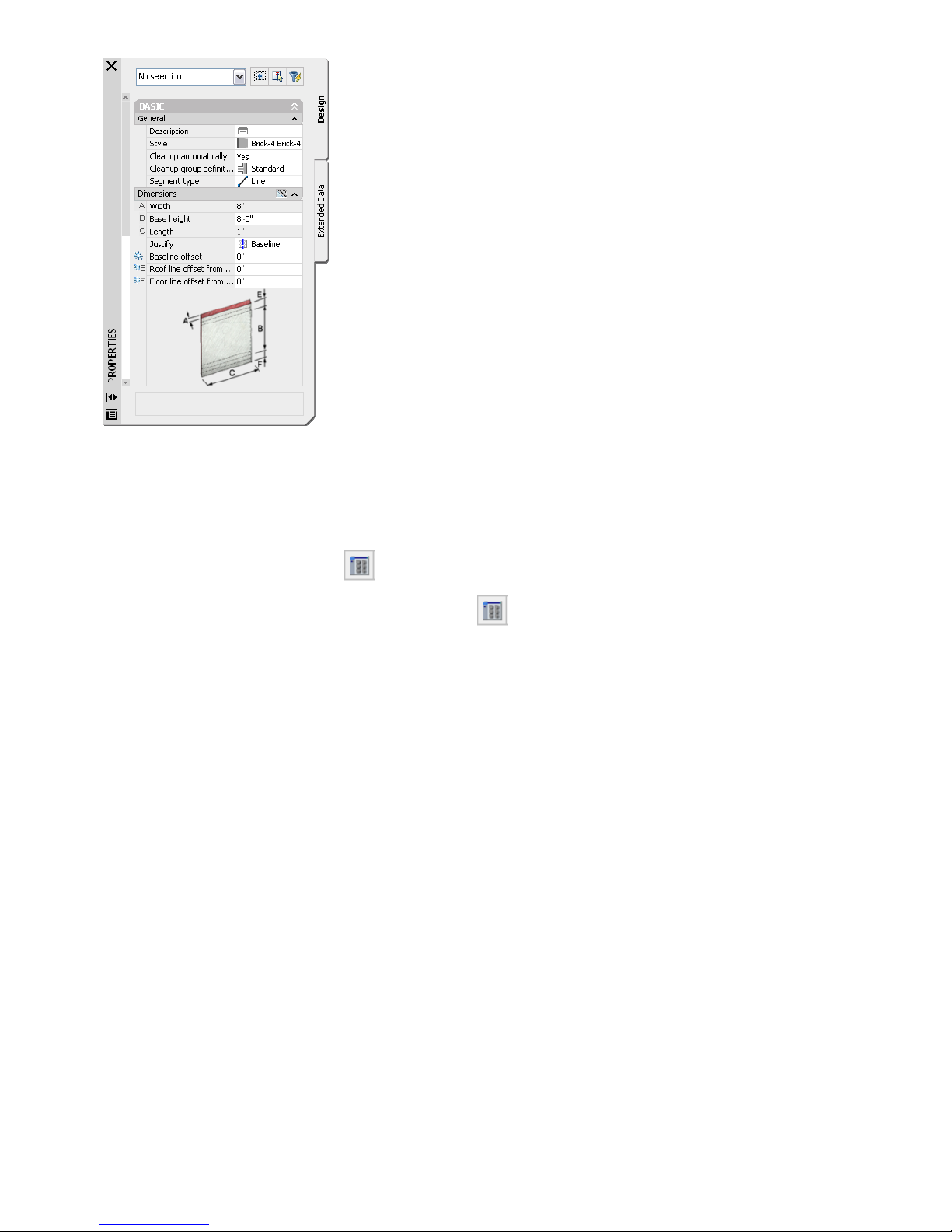
The Properties palette provides a single location where you can enter and change the properties of both Architectural
Desktop and AutoCAD objects. You can enter information about the style, dimensions, location, and other characteristics
of an Architectural Desktop object.
24 | Chapter 1 Introduction
Page 31
Content Browser
To display the Content Browser:
■ On the Window menu, click Content Browser.
■ On the Navigation toolbar, click .
■ On the bottom of the Project Navigator Palette, click (to access a project-specific tool library).
■ Press CTRL + 4.
The Content Browser lets you store, share, and exchange Architectural Desktop content, tools, and tool palettes. The
Content Browser runs independently of Architectural Desktop, allowing you to exchange tools and tool palettes with
other Autodesk applications, such as VIZ Render. Architectural Desktop tools and content are shared in the Content
Browser using tool catalogs and websites. Content that was only accessible from the DesignCenter in previous releases,
is now available as tools stored in the Content Browser.
A tool catalog can contain tools, tool palettes, and tool packages (collections of tools). Tool catalogs are placed in catalog
libraries. A Content Browser library can be set up on a shared network volume to be accessed by all users in a specific
project. The CAD manager or project owner can point the project to that Content Browser library to have quick access
to standard tools.
The Content Browser window is usually divided into two panes (web pages displayed in the Content Browser occupy
the entire window). Tool catalogs and their contents are displayed in the right pane. When you start the Content
Browser, your personal catalog library, named (<user_name>’s Catalog Library), displays in the right pane. The left pane
is used for navigation, searching for tools, sorting catalogs, and filtering catalog display.
Understanding the User Interface | 25
Page 32

The Content Browser
DesignCenter
To display the DesignCenter:
■ On the Insert menu, click DesignCenter.
■ On the Navigation toolbar, click .
■ Press CTRL + 2.
The DesignCenter™ provides another location where you can browse and share content, such as blocks and symbols,
between drawings. You can access content from your open drawings, drawings on your system, or drawings on a
network. A library of AEC (architectural, engineering, and construction) content included in Architectural Desktop is
accessible through the DesignCenter. Four tabs in the DesignCenter, (Folders, Open Drawings, AEC Content, and DC
Online), offer access to content in the different locations.
You can also access content on web pages with DesignCenter Online. DesignCenter Online provides access to catalogs
of manufacturer’s content that you can ''i-drop®,'' or select and drop into your drawings.
DesignCenter Online
26 | Chapter 1 Introduction
Page 33

You can drag content from the DesignCenter directly into a drawing or onto a tool palette to create a tool, but you
cannot drag tools directly from the Content Browser into the DesignCenter. Instead, drag tools that you create from
DesignCenter content from the tool palette into a catalog in the Content Browser.
Detail Component Manager
To display the Detail Component Manager:
■ On the Insert menu, click Detail Component Manager.
■ On the Navigation toolbar, click .
■ Right-click a detail tool on a tool palette, and click Detail Component Manager.
The Detail Component Manager provides access to industry standard detail components that you can insert in your
detail drawings. Detail components are 2D linework representations of specific building materials and products that
are stored in Microsoft® Access databases (MBD files). If the detail components that you want to use are not accessible
as tools on tool palettes, you can use the Detail Component Manager to select a component database and search for
specific components. Although you can insert the components directly into a drawing, you may want to drag any
components that you will use repeatedly from the Detail Component Manager onto a tool palette to create detail tools.
The Detail Component Manager
When you define or change project settings, you can specify the detail component database(s) that you want to use to
create project details, ensuring that all project team members use components from the same databases. Two detail
component databases are included with Architectural Desktop: one US-specific database that organizes components to
the CSI MasterFormat standard and one UK-specific database that organizes components to the NBS standard. You can
also specify a custom database.
When you insert a detail component, you can place multiple components, such as stacked bricks. You can insert detail
components in alternate views, such as section or elevation. Detail components are linked to a keynote that you can
use to automatically identify the component when you add annotation to the detail.
Arranging Your Workspace
You can arrange the toolbars and dockable windows, such as the palettes and the DesignCenter, in your workspace to
suit your design task or personal preference.
You can drag toolbars to position them in the workspace. You can drag toolbars to the sides and bottom of the drawing
window and dock them. After you arrange toolbars in your workspace, you can lock your toolbars into position. To
Understanding the User Interface | 27
Page 34

lock and unlock the position of the toolbars in the workspace, you can click or on the application status bar
at the bottom of your screen. On the menu that is displayed, you can lock or unlock all docked toolbars, all floating
toolbars, or all toolbars.
Windows, such as the Properties palette, the Tool palette, the Project Navigator palette, and the DesignCenter, can also
be docked, but only on the left and right sides of the drawing window.
The Tool Palette Set docked on one side of the workspace
To enable palette docking, right-click on the tool palette title bar, and click Allow Docking. Then, drag the palette to
either side of the window. You can lock and unlock palettes with the same option that you use to lock and unlock
toolbars. To control the size and listing of tools on palettes, right-click on a palette, and select View Options. You can
size the tools as appropriate for your screen resolution and workspace arrangement.
After you arrange your workspace, you can save it and then create additional workspace arrangements. You could
customize workspaces for particular design tasks, and switch between workspaces. The Workspaces toolbar contains
commands that allow you to save and switch between workspaces. For more information, see Use Workspaces in the
online AutoCAD 2006 User’s Guide.
28 | Chapter 1 Introduction
Page 35

Getting Started with Projects
2
The Drawing Management feature of Autodesk® Architectural Desktop software provides you with tools for creating
large building projects that are distributed among many drawing files. Drawing Management formalizes and
automates the organization and management of external reference files, letting you work with the logical pieces
of a building, as opposed to managing the file system.
In this part of the tutorial, you are introduced to the key concepts of Drawing Management as you begin the design
development phase of a sample commercial building project.
29
Page 36

Understanding the Tutorial Project
Autodesk Architectural Desktop and the tutorial dataset feature powerful tools to assist you in the creation of projects
and the design of a five-story office building. The office building consists of approximately 25,000 square feet per floor,
a three-story atrium area with an angled staircase, a centralized bank of elevators, and two emergency exit stairwells.
The interior building space also includes a typical central core of conference rooms, bathrooms, and storage rooms, in
addition to open space intended for future cubicle and office layouts. The tutorial covers new features that allow you
to create a project template. The project template has project standard object styles for use in all project drawings and
a project palette with tools specific to the building type. The goal of the tutorial is to have you create a project template
that is reusable for future work on buildings of the same type.
If you have not done so already, you should install the small office building dataset. The first two lessons in this part
of the tutorial involve creation of a project template for an office, an exploration of drafting technique in that you
refine a sketch to produce generic object, then replace the generic objects with styles representing the finished building
components. The third and last lesson of this part shows how to version styles, update the project standard styles and
then populate the project drawings with the latest version of a style from a single source - the project standards. You
also see how a new or revised object style can be uploaded to the project standards from a project drawing, so as to
make it available for project tools and the validation of all project drawings.
Lesson 1: Setting up the Small Office Building Sample Project
As you begin the design development phase of a project, you familiarize yourself with the requirements of the project
as outlined in the design program and conceptual drawings. Often you can begin to identify design objects that will
be repeated throughout the building model, such as specific types of walls, doors, and windows. In Architectural
Desktop, you can create tools that represent your most frequently-used design objects, allowing you to add objects
such as walls, doors, and windows to your drawings quickly and easily.
This lesson introduces you to the key concepts essential to working with projects that are organized and managed in
a project environment. This introduction focuses on the fundamental information you need to be successful as you
begin your work with projects. For in-depth coverage of project-related topics, use the cross-references provided
throughout the lesson. Finally, you create a new project, which forms the basis for future work. You create a project
template, with project standards styles and tools. This is a one-time task that lets you see how you can create templates
for the building types you specialize in. When you have finished the project for use as a template, you can then begin
any similar project with all the required standards configured and project-specific tools readily at hand in project-specific
palettes.
Exercise 1: Exploring Project Drawings
This exercise introduces you to the terms and concepts that are essential to working in a project environment by
exploring the contents and structure of a sample project. This introduction focuses on the fundamental information
you need to be successful as you begin your work with projects. For in-depth coverage of project-related topics, use the
cross-references provided throughout the exercise.
As you explore the sample project, you work with two key components of the project environment: the Project Browser
and the Project Navigator. In the Project Browser, you create a new project, or select an existing project in which to
work. In the Project Navigator, you perform all project-specific tasks, such as creating, organizing, and accessing project
drawings. In this exercise, you use the Project Browser to open the Small Office Building Sample Project. You use the
Project Navigator to explore the contents and organization of this project.
The Project Navigator is a palette that remains open during your project session. The Project Navigator gives you access
to the various drawings that make up your building model, and it allows you to control the way in which your building
model is organized into a project.
Conceptually, a project is composed of two parts: the building model and the reports that are generated from the
building model. The building model is made up of two types of drawing files: constructs and elements. Reports are made
up of views and plot sheets, which are also drawing files. This exercise introduces you to these key project components,
as you explore the structure that allows you to effectively organize the building and documentation data that make up
your project.
Open the Project Browser
1 On the File menu, click Project Browser or, on the Navigation toolbar, click .
30 | Chapter 2 Getting Started with Projects
Page 37

At the top left of the Project Browser is the project header. When you select the project you want to work with,
the project header displays the project name, project number, optional bitmap image, and optional project
description. You enter this information when you create a new project or edit an existing one. Unless you have
added and selected another project, the Project Browser shows New 2006 Project as your current project. New 2006
Project is a default project you can use.
Below the project header is the project navigation toolbar, which helps you navigate the operating system and
control the order of the project listing.
Below the project navigation toolbar is the project selector. The project selector displays the projects you have
created in Architectural Desktop, and allows you to browse to locations where projects are stored. You also use the
project selector to select the project environment in which to work.
TIP: Use the drop-down list for the project folder location to browse to the installed projects. The Small Office Building
project, by default, is installed to \my documents\autodesk\my projects.
If you are using Architectural Desktop in a network environment, the tutorial files may have been installed in a
different location. Contact your network administrator or CAD manager for the location of the tutorial files.
Select the project environment in which to work
2 In the Project Browser, right-click Small Office Building_I, and click Set Project Current. You can also double-click
a project name to make it current.
3 If prompted to re-path the project, click Yes.
When you move a project, you need to re-path the project to update the external reference paths.
Small Office Building_I is set as the current project environment. The current project is displayed in bold text in
the project selector. The project header displays the project name, project number, project image, and project
description that were entered when the project was created.
Lesson 1: Setting up the Small Office Building Sample Project | 31
Page 38

The right window of the Project Browser is the project bulletin board. It is an HTML page that is linked to the
project. When you create a project, you can link it to an Internet home page, such as your company’s home page
or a project Web site. The navigation toolbar below the bulletin board includes icons for Back, Forward, Stop,
Refresh, and Project Home. A project bulletin board is a way to communicate with project members about project
meetings, issues with the drawings, share site photographs or connect to other documentation such as animations
and DWF files.
4 Click Close to close the Project Browser.
The Project Navigator is displayed. If the Project Navigator is not displayed, click Project Navigator Palette on the
Window menu.
View project information in the Project Navigator
5 Verify that the Project Navigator is displayed.
The Project Navigator has four tabs on which you can enter project data. The tabs correspond to the main phases
of project creation: defining general project information, creating building data, and creating building documentation
(views and sheets). Next, you view the Project tab.
6 Verify that the Project tab is displayed.
Define building divisions and levels on the Project tab
On the Project tab, you can use the edit icon and then enter information that pertains to your whole project,
such as the levels and divisions that make up your building model. Levels are the floors in your building model;
divisions are locations such as the main building or the west wing. Together, levels and divisions create a framework
that allows you to label unique portions of your building model. For example, you could have an arrangement of
offices in your building named 01 Offices and assigned to First Floor - West Wing.
By default, a new project consists of one level and one division. You can add and modify levels and divisions
throughout the life of the project.
The sample project in this tutorial consists of six levels (five floors and a roof level), and a single division (main
building). Next, you preview drawings, and review level and division assignments for constructs.
Explore constructs and construct categories
7 Click the Constructs tab.
Constructs are the main building blocks of a building model.
TIP: The illustrations show the project drawings. On your screen you will also see exercise files with an X- prefix.
32 | Chapter 2 Getting Started with Projects
Page 39

Create, edit, and organize constructs on the Constructs tab
8 Under the Constructs folder, locate the Architectural folder and the Structural folder at the next level in the
hierarchy.
The Architectural folder and the Structural folder represent construct categories. In this sample project, the constructs
are categorized by discipline: Architectural and Structural. Each discipline category contains subcategories, such
as Building Outline and Partitions. Categories help you organize the various parts of your building project. As you
explore the sample project in this exercise, notice the categories that have been established. In the next lesson,
you create a new project and establish a set of categories to be used throughout the project.
9 Locate the Partitions folder.
Like the other folders at this level of the sample project, the Partitions folder contains individual construct drawings.
10 Click 02 Floor Partitions.
11 If the Detail pane is displayed below the Constructs tree, click to display a preview of the 02 Floor Partitions
construct in the Preview window.
A construct is a drawing that represents a unique portion of the building model, and is assigned to a specific level
and division within the project.
Lesson 1: Setting up the Small Office Building Sample Project | 33
Page 40

12 Right-click 02 Floor Partitions, and click Properties.
13 Under Assignments, notice that the 02 Floor Partitions construct is assigned to Division 1, Level 2.
Most projects require that each level and division be represented by multiple constructs. For example, the second
floor of the sample project is made up of the 02 Floor Partitions construct, the Typical Floor Shell construct, and
the 02 Floor Slab construct. Spanning constructs, such as Typical Floor Shell, drawn in one drawing to span multiple
levels and assigned to multiple levels.
34 | Chapter 2 Getting Started with Projects
Page 41

Any number of constructs may be assigned to the same portion of the building. The more complex your building
project, the more beneficial proper categorization becomes in organizing and managing the building model data.
By describing each portion of your building model as a unique construct, you can easily create specific views of
your building project. Later in this exercise, you explore views that have been created using the constructs on the
Constructs tab. When you create a view, you are asked to identify the location (level/division), and are presented
with a list of potential external references for the view.
14 Click Cancel.
15 Preview two or three constructs from different categories, not including the Elements folder. Elements are a separate
type of project component and are explored next.
Explore elements
16 On the Constructs tab, scroll to the Elements folder.
The Elements folder on the Constructs tab
17 Click Typical Core to display a preview of this element.
Elements are the smallest building blocks within a project. Usually, an element is a repeating design object in the
building model that is referenced into multiple constructs. In the sample project, the Typical Core element was
drawn once and referenced into four constructs: 02 Floor Partitions, 03 Floor Partitions, 04 Floor Partitions, and
05 Floor Partitions.
An element is a repeating component in the building model, so it has no level or division assignment. To place
an element on a specific floor and division, you need to reference the element into a construct. A construct has a
level and division assignment.
Explore views and view categories
18 Click the Views tab.
After the structure of the project is defined and constructs are created and assigned to levels and divisions, you can
begin creating views. A view references one or more constructs to present a specific view of the building project.
To create a view, you decide what portion of the building you wish to see, and which type of view you wish to
generate. You could, for example, create a second-floor plan or an exterior elevation view. You could also create a
composite 3D view of the building model.
Notice that the views for the sample project have been categorized based on architectural features and the interior
and exterior views of the building model. Categories help you organize the various parts of your building model
and the reports that are generated from it.
Lesson 1: Setting up the Small Office Building Sample Project | 35
Page 42

Create, edit, and organize specific views of the building model on the Views tab
19 Under Interior, click 02 Floor Plan.
20 Click to display a preview of the 02 Floor Plan view.
Views reference the appropriate constructs according to their location within the building. When you create a view
of the building model, you select the level or levels for which you want to create the view, and all constructs
assigned to that level are referenced into the view drawing automatically. The 02 Floor Plan view was created by
selecting level 2, which automatically referenced all constructs that were assigned to level 2: Typical Building
Outline, 02 Floor Partitions, Typical Floor Shell, Column Grid, and 02 Floor Slab.
When you create a view, you can exclude individual constructs that are assigned to the portion of the building
model for which you are generating the view. For example, in 02 Floor Plan, the building outline construct assigned
to level 2, Typical Building Outline, was excluded. You can also include additional constructs as needed, such as
a structural framing construct assigned to another floor, which you want to see in the 2 floor plan.
You can add annotation to a model space view, much like you added annotation in model space in previous releases
of Architectural Desktop. As shown next, you can also add annotation to plot sheets, much like you added annotation
in paper space in previous releases of the software.
Explore sheets
21 Click the Sheets tab.
Plot sheets reference model space views, and can be used to add annotation data to the project. In the sample
project, the plot sheets represent a set of construction documents for your building project.
On the Sheets tab of the Project Navigator, you can create and manage the plotting sheets for a project. You work
with the project sheet set, and can perform tasks that affect the entire sheet set, such as creating a sheet list or
publishing the sheet set. You can also create sheet subsets; open sheet views; assign numbers to sheet views; and
add, modify, or delete sheets in the project.
Notice that the Sheet Set View displays the hierarchy of sheets and sheet subsets for the sample project.
36 | Chapter 2 Getting Started with Projects
Page 43
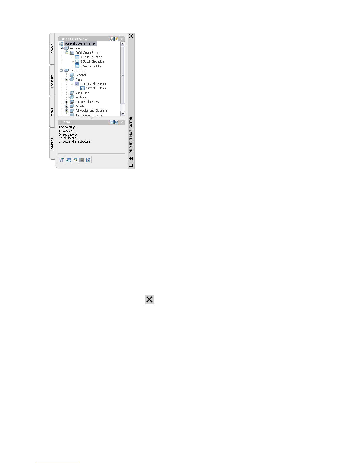
Create, edit, and organize plot sheets on the Sheets tab
22 Under Architectural\Plans, double-click A102 02Floor Plan to open the sheet in the drawing area.
23 Examine the view displayed in the sheet.
This sheet contains an external reference to the 02 Floor Plan view. After the sheet was added to the project, the
02 Floor Plan view was dragged onto a paper space layout in the A102 02 Floor Plan sheet. When you drag a model
space view from the Project Navigator onto a paper space layout in a sheet, the following actions take place:
■ The view drawing is externally referenced into the plot sheet drawing’s model space.
■ A viewport is created on the current layout, scaled according to the settings held in the model space view’s
properties.
24 Examine the overall building dimensions.
The dimensions in this drawing were added to the view. Optionally, you could add annotation, such as schedule
tags and tables, dimensions, and title marks to the plot sheet. Whether to create annotation on plot sheets or in
views is a decision you should make based on your workflow and individual needs. For example, using callout
tools creates a workflow in which annotation, tags, and titles are placed in views.
25 On the File menu, click Close to close the sheet, and click No when prompted to save the drawing.
26 In the Project Navigator title bar, click to close the Project Navigator.
In this exercise, you explored the Small Office Building Sample Project, while being introduced to the terms and concepts
that are essential to working within a project environment. Using the Project Browser, you accessed the Small Office
Building Sample Project, and selected it as the project environment in which to work. In the Project Navigator, you
viewed the organization and contents of the default project categories: Constructs, Elements, Views, and Sheets. The
relationships among these project components can be summarized as follows: Within a project, elements are referenced
into constructs, constructs are referenced into views, and views are referenced into sheets.
Exercise 2: Creating a Set of Project Tools
In Autodesk® Architectural Desktop, you can use tools to add architectural objects, annotation, and documentation
to your drawings. The tools are organized on tool palettes, which are groups of tools that support particular tasks or
processes. For example, the Walls tool palette contains tools for several commonly-used interior and exterior wall styles,
while the Documentation tool palette contains tools for working with schedules and areas. To use a tool, simply click
the tool on the palette and begin drawing in the drawing area.
When you install the software, several tool palettes are provided. You can begin using these default tools right away.
You can modify the tools on these palettes, or create new tools and palettes to meet your project-specific needs.
Lesson 1: Setting up the Small Office Building Sample Project | 37
Page 44

You can assemble your tools and tool palettes into catalogs. Your library of catalogs is stored in the Content Browser.
You use the Content Browser to store and retrieve your complete inventory of stock and custom tools, content, and
tool palettes.
This exercise shows how to open a tool catalog in the Content Browser, and retrieve a tool palette that contains
architectural object tools. In later exercises, you use tools to add objects such as slabs, walls, and doors to your drawings.
The objects you add with these tools behave like their real-world counterparts. For example, a wall tool has all of the
parameters of real wall components built into it. When you add a wall to your drawing, you can use the default
parameters or modify them.
Like all architectural objects in Architectural Desktop, a wall is a “smart” object that adheres to a set of built-in rules
that control its behavior under certain circumstances. For example, if you add a door to a wall, the door cuts an opening
in the wall, and the endcaps of the wall adjust to accommodate the dimensions of the door. If you move the door along
the wall, the opening moves with the door. If you remove the door, the opening in the wall is removed as well. In this
way, architectural objects interact with other building model objects and update dynamically to reflect design changes.
In addition to rule-based behavior and dynamic updates, architectural objects have another advantage over traditional
drafting with lines, arcs, and circles: display representations. Architectural objects can be represented two-dimensionally
or three-dimensionally, all with a single object. Therefore, you can add the object once, and then use different built-in
representations of the object to produce different views of the object, such as a plan or model view. When you modify
an object, the change is reflected in all views.
Tools make it easy to add and modify objects in Architectural Desktop. Using tools effectively and collaboratively in a
project environment can increase productivity and reduce drawing errors.
Add a tool palette for the sample project
1 If you have not already launched Architectural Desktop, double-click the Autodesk Architectural Desktop 2006
icon on your desktop.
2 Verify that the tool palettes set is displayed.
To display the tool palettes set, click Window ➤ Tool Palettes.
3 Open the Content Browser by clicking on the Navigation toolbar.
The Content Browser holds your library of tool and content catalogs. You can store and retrieve your own customized
tools, content, and tool palettes, and you can share tools and palettes with other members of your design team
through your intranet or the Internet.
4 Double-click Sample Palette Category - Imperial.
5 In the left pane of the Content Browser, click Document.
6 Click next to Scheduling palette, and drag it onto the tool palettes set.
When you move the cursor over the i-drop® icon, the cursor changes to a dropper image, indicating that you are
in insertion mode. Use the i-drop insertion method to drag and drop content from catalogs into your current
drawing. The tools from the Content Browser are designed for general use. Tools can be customized for a project
and you will do this in tutorial exercises.
38 | Chapter 2 Getting Started with Projects
Page 45

The Scheduling palette is added to your existing tool palettes. You can use the Content Browser to access additional
content and tools that are not displayed in the default tool palettes. It is also an option to share palettes. Managing
shared tool palettes ensures that all project team members use the most current tools created or modified for a
particular project or function. When a tool palette is shared from a catalog, the Refresh icon ( ) is displayed in
the lower right corner of the palette to allow updates from the source palette.
Working with floating tool palettes
7 You can work with tool palettes in two ways: floating or docked. Floating tool palettes can be moved within the
drawing area, resized, and hidden. Docked tool palettes are placed in a specific location in the drawing area, and
they remain in that location unless you turn off the docking option and move the tool palettes. If your tool palettes
are docked and you want to switch to floating tool palettes to complete this exercise, right-click the top edge of
the tool palettes, and then click Allow Docking.
Resize the tool palettes set by dragging the bottom edge of the tool palettes set down until all tabs are visible.
8 Right-click on the tool palette bar and select Design.
9 Click the Doors tab to view the contents of this tool palette.
Each tool palette contains a group of related tools. You can modify the tools on a palette, or create new tools and
palettes.
10 Click the stacked tabs on the tool palettes set to display the list of available palettes, and click Windows.
The Windows tool palette is displayed. When there are more tool palettes than can be displayed within the current
height of the tool palettes set, the tabs are “stacked” at the bottom. The list of tool palettes shows all available
palettes. The tab names that are displayed below the line on the list are the ones that are hidden.
11 Click Auto-hide ( ) on the title bar of the tool palettes set, and move the cursor off the tool palettes set.
When you select Auto-hide on any palette title bar, only the palette title bar is displayed when the cursor moves
off the palette. You may prefer to minimize palettes to their title bars when working in the drawing area. If you
click the Auto-hide button again, the full palette is displayed when the cursor moves off the palette.
TIP: You can rearrange the order of the tool palettes. To move a tool palette, right-click its tab, and click Move Up or
Move Down.
12 Right-click on the tool palette bar and select the project palette group, Small Office Building_I.
In this exercise, you added the Scheduling palette to the collection of tools available on the Tool palettes. Using the
Content Browser, you opened the Sample Palette Catalog, and dragged the Scheduling palette onto the Tool palettes.
In this lesson, you reviewed the structure of a project within the Project Navigator and were introduced to the terms
and concepts that are essential to working within a project environment. You then added a palette for you project from
the Content Browser.
In the remainder of this tutorial, you create a project template, which you reuse for buildings of the same type (small
office project).
Next, you define the building elevations in the Project Navigator. You work in the Project Navigator for the remainder
of the tutorial to develop and document your building model.
Lesson 2: Setting up Your Project Template
In this lesson, you create a new project and refine it for use as a template. You use drawings from a previous project to
establish standards for object styles and create project tools. You learn how to quickly convert linework sketches to
building objects using tools.
This lesson shows how to define building levels and add categories to the Small Office Building template. The additions
you make to your project environment and building model in this lesson lay the groundwork for developing future
projects and managing their project standards.
As you set up a new project, you work with two key components of the project environment: the Project Browser and
the Project Navigator. In the last lesson, you used the Project Browser to create the new project. In this lesson, you
define building elevations and categories for the new project using the Project Navigator.
Lesson 2: Setting up Your Project Template | 39
Page 46

Exercise 1: Creating a Project Template
In this exercise, you create a new Architectural Desktop project that you will use as a template for the small office
building project that you will create later. The project structure stores not only project drawings, but also:
■ a Content Browser library for project tools
■ content files for the tools (project walls, doors, and windows)
■ a custom tool palette with project-specific tools
■ project standard styles for AEC objects
Structuring a project in this manner allows it to be archived or transmitted to others with all the required content
under one project folder. It can also be used as a project template, so that if you created a project for a building type,
such as schools, then you could re-use the project and have all the custom tools available when you begin the new
project.
At the end of the exercise, the project will be structured as shown:
Create a new project to develop as a template
1 On the File menu, click Project Browser or click on the Navigation toolbar.
Use the default project folder c:\my documents\autodesk\my projects.
2 In the lower left corner of the Project Browser, click .
3 On the Add Project worksheet, specify the following information:
■ Enter ADT101 for Project Number.
■ Enter Small Office Building for Project Name.
■ Enter A prototype project for commercial office space for Project Description.
4 Clear Create from template project, and click OK.
40 | Chapter 2 Getting Started with Projects
Page 47

You have just created a project folder with a file to track project drawings (*.apj), a file to manage project sheets
(*.dst), and folders for different drawing types. These files and folders for storing project drawings were created
automatically: you did not have to work outside Architectural Desktop to create them.
View the current project in the Project Browser
5 The project is now using the locations of the installed product for the bulletin board, project image, and templates.
There are no automatic standards, project Content Browser library or project-specific tools. Tools are delivering
content from the styles drawings. If you want to apply standards to the project, including templates, standards
(object styles and AutoCAD), and add Content Browser library and tools, you can create these on a project by
project basis. The paths to content are definable for each project so that you can decide on any combination of
company-wide content (templates, standards, Content Browser library, tools) and content that is project-specific.
If you want to create a project where templates, bulletin board, standards, and tools are project-specific, you can.
The benefit to this approach is that you can ensure that all required content is stored under a project folder so you
can more easily transmit whole projects with tools and standards. You can also use a project as a project template
for a specific building type, such as a commercial office, school or hospital template.
6 In the Project Browser, click Close.
The Project Navigator is displayed, with the Small Office Building project current and a project palette group is
created automatically.
NOTE: The project tool palette group is created, but not displayed in the tool palettes set, because it does not yet contain
any tool palettes. To add tool palettes, and make the tool palette group visible, click in the tool palettes set title bar, click
Customize, and add a palette to the project group in the Customize dialog box. When you click Close, the project tool
palette group can now be selected in the tool palettes set.
Lesson 2: Setting up Your Project Template | 41
Page 48

7 With the Project Navigator open, click the Project tab.
Define a location for project tool palettes
8 Click in the Project title bar to display the Modify Project dialog box.
9 Click in the Tool Palette File Location field and click the browse icon that is displayed.
10 In the Browse for Folder dialog box, navigate to the My Documents/Autodesk/My Projects/Small Office Building folder
and view the folder structure. With Small Office Building folder selected, click OK. This is where you will keep
project-specific tool palettes - within your project.
42 | Chapter 2 Getting Started with Projects
Page 49

12 Click in the Tool Palette Storage Type field and select Shared Workspace.
The Per User option will allow you to change your palettes without affecting anyone else. The Shared Workspace
option is used where changes to the tools will affect everyone using the project tools. Typically the CAD Manager
will decide on an appropriate option for your application. The Shared Workpace option was used for the tutorials
so that the delivered dataset can include project tools.
Create or define a location for tool content (object styles)
13 In the Tool Content Root Path, click the Browse icon.
14 In the Browse for Folder dialog box, click the Small Office Building folder and click Make New Folder. Create a new
folder named Standards, and then create the subfolders Object Styles and ACAD_DWS in the new Standards folder.
These folders are where you will store drawings containing project-specific object styles or AutoCAD DWS files.
The tool content path should be to the folder with drawings containing object styles. With the object styles in
standards drawings at this location you can both apply those standards across all project drawings and create
project tools that use the standard object styles. The benefit to you is that you can manage object styles in one
location. Changes to an object style will immediately update the tool and you can, through a process of validation,
apply versioned standards across all project drawings. A change to a wall style, such as a change in materials, in
the drawing identified as a standards drawing can be applied across all project drawings. The scenario, in this
tutorial, is to keep the process simple with one drawing for standards and project tools and one location under the
project folder. In this way the entire project can be managed as a self-contained project.
Later in this tutorial you will place a drawing containing object styles in the Object Styles folder. You will configure
the object styles within that drawing as project standards and you will generate project tools from the standards
drawing.
Lesson 2: Setting up Your Project Template | 43
Page 50

TIP: The folders do not need to be in your project, and you can have multiple locations for project standards. Wherever
your standards are, they can be applied to all project drawings. For example, you can ensure that any specific window
style with its materials is the same in all project drawings. Changing it at the source will allow it to be updated in all
project drawings.
15 With the Object Styles folder selected, click OK three times.
Create a new Content Browser library for your project
16 On the Project Navigator, click .
17 In the left pane of the Content Browser, right-click, and click New Library.
18 In the Create New Library dialog box, change the Save in location to your project folder (Small Office Building).
19 Enter Small Office Building for File Name.
20 Click Save. You created the project Content Browser library but you have not completed the project data to locate
the library.
21 Minimize the Content Browser.
Locate the Content Browser library for your project
22 On the Project tab, click in the Project title bar.
23 In the Tool Catalog Library field, click the Browse icon.
24 In the Tool Catalog Library dialog box, browse to the new project folder and select Small Office Building.cbl.
44 | Chapter 2 Getting Started with Projects
Page 51

25 Click Open.
26 In the Modify Project dialog box, click OK.
Verify the project library is connected
27 On the Project Navigator, click the Content Browser icon.
This is an empty library where you can add content. By creating the separate library, you control the content seen
by the project team. You reduce the time in searching for content because you can limit the amount of content
and ensure it is relevant to the project. The Content Browser icon on the Project Navigator locates the defined
project library, whereas the Content Browser icon on the Navigation tools locates the library for all the delivered
content.
Add a catalog to your library
28 Right-click in the left pane of the Content Browser and select Add Catalog.
29 To add an existing catalog, verify Add an existing catalog or web site is selected, click Browse, and select \my
projects\small office building\small office building.atc. The catalog with a project tools group was created automatically
when you created the project.
30 Click Open, and then click OK.
The items that are currently not beneath your project folder are the bulletin board, project image and template
files.
Lesson 2: Setting up Your Project Template | 45
Page 52

Copy files from the installed tutorial projects for use in your project.
31 Open Windows Explorer and browse to the my documents\autodesk\my projects\small office building folder.
32 Create two new folders named Templates and Supplemental in the Small Office Building folder.
33 Copy files from the folders in Small Office Building_I to the corresponding folder in your project. The files you
need are in the Supplemental and Templates folders.
34 Minimize Windows Explorer.
Locate the project bulletin board and project image
35 On the Project tab, click in the Project title bar.
36 In the Bulletin Board field, click the Browse icon.
37 In the Bulletin Board dialog box, browse to the my documents\autodesk\my projects\small office building\supplemental
folder and select Small Office Building.htm.
38 Click Open.
39 For the Project Image, browse to the same folder, select logo.bmp, and click Open. You could include your client’s
logos for the project.
46 | Chapter 2 Getting Started with Projects
Page 53

Locate template files for project drawings
40 In the Default Construct Template field, click the Browse icon.
41 In the Default Construct Template dialog box, navigate to the my documents\autodesk\my projects\small office
building\templates folder and select AEC Model (Imperial.Stb).dwt.
42 Click Open.
43 In the Default Element Template field, click the Browse icon.
44 In the Default Element Template dialog box, navigate to the my documents\autodesk\my projects\small office
building\templates folder and select AEC Model (Imperial.Stb).dwt.
45 Click Open.
46 In the Default Model View Template field, click the Browse icon.
47 In the Default Model View Template dialog box, navigate to the my documents\autodesk\my projects\small office
building\templates folder and select AEC Model (Imperial.Stb).dwt.
48 Click Open.
49 In the Default Section/Elevation View Template field, click the Browse icon.
50 In the Default Section/Elevation View Template dialog box, navigate to the my documents\autodesk\my projects\small
office building\templates folder and select AEC Model (Imperial.Stb).dwt.
51 Click Open.
52 In the Default Detail View Template field, click the Browse icon.
53 In the Default Detail View Template dialog box, navigate to the my documents\autodesk\my projects\small office
building\templates folder and select AEC Model (Imperial.Stb).dwt.
54 Click Open.
55 On the Modify Project Worksheet, click OK.
TIP: There is a structural template which contains a display configuration for working with structural members. This was
used for the Steel-Framed Residential project.
Exercise 2:Adding Legacy Drawings to the Project
In this exercise, you add two ''legacy'' drawings (DWGs) to the current project. The drawings represent sketches of the
first floor shell and typical core that you want to use to create the first floor shell and core of the current building
project. You can include AutoCAD and AutoCAD LT drawings in your project and manage them in the Project Navigator.
These exercise files are included to show you to add existing drawings to a project and how to use existing linework to
create AEC objects quickly.
To copy the drawings to the project, you hold the CTRL key and drag them from the tutorial dataset folder, named
LegacyDrawings, using Windows Explorer, to the project folders in the Project Navigator. The first floor shell sketch
represents a unique location in the building model (the first floor), so you add it to the project as a construct. Because
you will use the core sketch to create core geometry that you will reference onto each floor of the building to form the
core, you add it to the project as an element.
Drag the drawings into the project navigator
1 With the Project Navigator open, click the Constructs tab.
The Constructs tab contains two folders, Constructs and Elements, where you will add the two drawings.
2 Open Windows Explorer and navigate to the my documents/autodesk/my projects/small office building_I/legacydrawings
folder.
The two drawings that you add are X-Sketch_01 Floor Shell_I.dwg and X-Sketch_Typical Core_I.dwg.
3 Minimize Windows Explorer on your screen so you can view both the drawings in the Explorer and the Project
Navigator in Architectural Desktop.
Lesson 2: Setting up Your Project Template | 47
Page 54

4 In Windows Explorer, press and hold CTRL, select both drawings, and drag them to the Elements folder.
5 On the Add Element worksheet, click OK to add the first drawing to the project as an element.
6 Click OK again to add the second drawing to the project as an element.
Both drawings are now added to the project as elements. Because the first floor shell drawing has a uniquely assigned
location in the building model, you must reassign it as a construct in the project.
Reassign the first floor shell sketch to the project as a construct
7 Under Elements, select the X-Sketch_01 Floor Shell_I.dwg file and drag it to the Constructs folder.
8 On the Add Construct worksheet, under Assignments, select Division 1, and click OK.
48 | Chapter 2 Getting Started with Projects
Page 55

The first floor shell sketch is now added to the project as a construct and assigned to the first floor of the main
building (division 1) within the project.
Add a drawing with object styles
9 Open Windows Explorer and copy the Styles_STD.dwg file in the my documents/autodesk/my projects/small office
building_I/standards/object styles folder to the my documents/autodesk/my projects/small office building/standards/object
styles folder. You will use the styles in this drawing to configure standards and to generate project tools.
The first floor shell sketch is now added to the project as a construct and assigned to the first floor of the main
building (division 1) within the project. The legacy drawing representing a collection of styles you wish to be
standard has been copied to your project.
In this exercise, you added sketches of the first floor shell and typical core geometry that you want to reference on each
floor. You also copied a drawing containing objects to the standards\object styles folder. You will use this to create
project specific standards and tools. In the next two exercises, you create project standards and tools and you use the
sketches to create finished objects in each drawing by converting linework.
Lesson 2: Setting up Your Project Template | 49
Page 56

Exercise 3: Configuring Project Standards
In this exercise, you define drawing files for project standards. In this example we are using our project standard
Styles_STD.dwg file for all AEC objects.
Open the Small Office Building Project
1 If the Small Office Building project is not already open, on the File menu, click Project Browser to open the Project
Browser dialog box.
2 Double-click Small Office Building to set the project as active.
3 Click Close.
Configure Project Standards
4 On the Project tab of the Project Navigator, select Configure Project Standards. These standards can be for
AEC object styles and AutoCAD standards. The Configure AEC Project Standards dialog box opens.
5 Select Enable project standards for project ADT101 - Small Office Building.
6 Select the AutoCAD Standards tab to verify that you can add an AutoCAD DWS file for AutoCAD standards. This
would be used to apply standards such as for linetypes, text styles, or dimension styles.
7 Select the Standard Styles tab.
8 Verify that All Objects is displayed for Select which objects to display in the list below.
50 | Chapter 2 Getting Started with Projects
Page 57
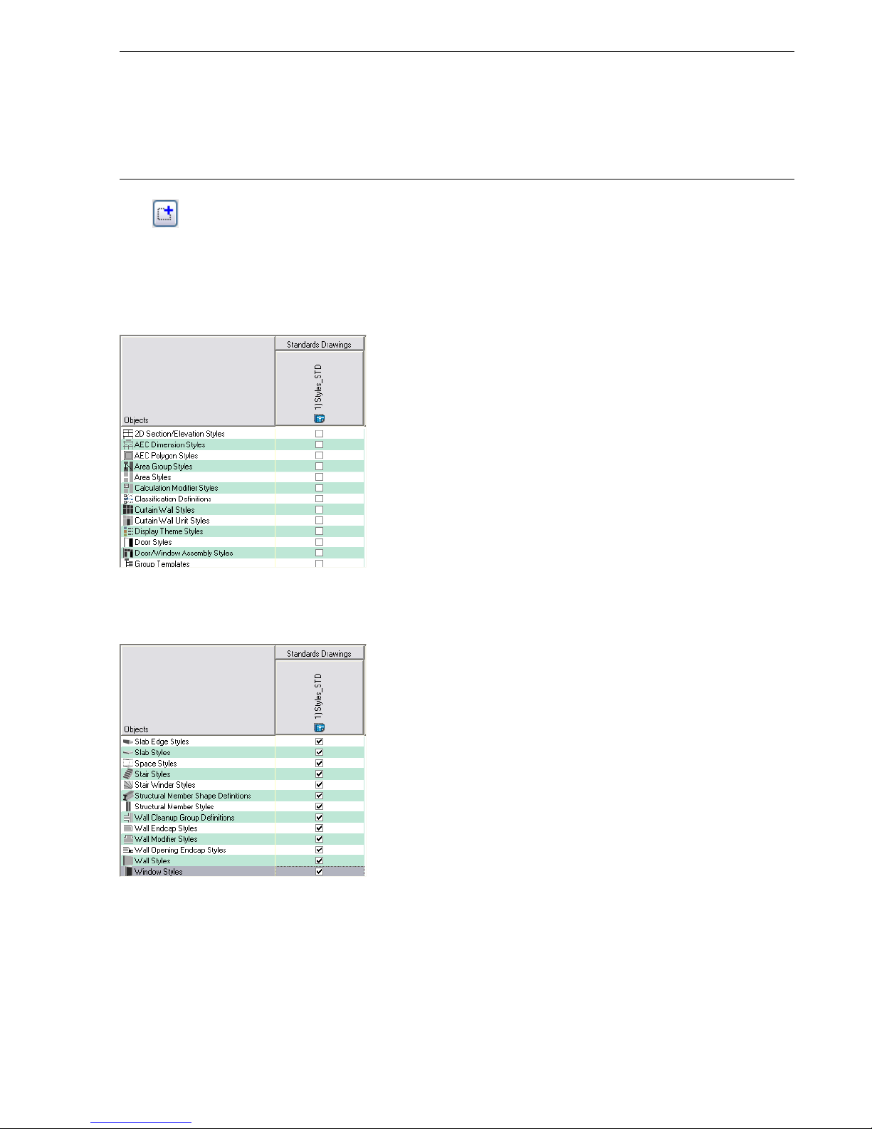
TIP: You can specify multiple drawings for standards. You can define which AEC styles you see in the list (All Objects,
Architectural Objects, Documentation Objects, and Multi-Purpose Objects), and you can select the style in the displayed
list. In practice you could be more granular in how you organize the standards, for example having a Walls_STD.dwg
and a Structural_STD.dwg. When you have multiple drawings for standard validation and the same AEC style, for example
wall styles, is checked in more than one standard file, then the order of the drawings is important with the priority being
assigned to the leftmost standards drawing. Validation checks the drawings from left to right, so the first selected drawing
that has the style type selected is used as the standard.
9 Click Add Drawing. The minus removes drawings and the order can be changed if you assign multiple standards.
The Select Standards Drawing dialog box opens.
10 Navigate to the my documents/autoCAD/my projects/small office building/standards/object styles folder and select
Styles_STD.dwg.
11 Click Open.
The Styles_STD.dwg is displayed in the Standards Drawings column heading.
12 With All Objects selected, select all style types. When you use the Style Manager you will see the Styles_STD.dwg
listed as a standards drawing for the project. Styles within the standards drawing that are checked as standard styles
will display in the Style Manager with a blue color.
Configure the standard for display settings
13 In the Select drawing to use for standard display settings list, select Browse.
14 Navigate to the my documents/autoCAD/my projects/small office building/standards/object styles folder and select
Styles_STD.dwg.
The Styles_STD.dwg file is your source for display configurations. This gives you one location where you can make
changes and apply them to all project drawings.
Lesson 2: Setting up Your Project Template | 51
Page 58
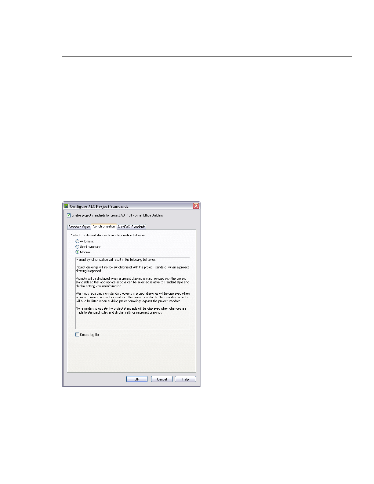
TIP: You can locate standard files in the project folder or anywhere on your network. Since you can define multiple
standards drawings, you can combine office standards from a location on your network with project-specific standards,
in this case, located in the project folder. Make sure that the standards files are not located on a mapped network drive;
the Drawing Management feature cannot use files from a mapped network drive.
15 Click Open.
Decide how the standards validation should be applied to project drawings
16 Click the Synchronization tab.
The options on this tab are as follows:
■ Automatic, where you see no confirmation of updating standards which are validated when you open a project
drawing.
■ Semi-automatic, where you see a dialog box when you open a project drawing and you decide which items to
update.
If you select Automatic or Semi-Automatic synchronization, the synchronization dialog can also appear upon
saving and closing a project drawing, provided there have been changes to the standards.
■ Manual, where you must initiate validation, the standards check, and confirm changes in the synchronization
dialog box.
17 Select Manual.
18 Clear Create log file.
If selected, this would create an .htm or .xml log file that documents changes as you validate.
19 Click OK.
20 In the Version Comment dialog box, enter Initial Standards.
21 Click OK. All the styles are versioned automatically with today’s date when you define a drawing as a standard.
From this point on, you can manage the styles individually, versioning a standard and updating the standards
from the project drawings. The technique for managing the standards is through use of the Style Manager.
52 | Chapter 2 Getting Started with Projects
Page 59

Exercise 4: Generating Project Tools from a Project Standards Drawing
In this exercise, you create tools for your project catalog from the standards drawing, Styles_STD.dwg.
Generate project tools
1 On the File menu, click Open.
2 Browse to the my documents/autodesk/my projects/small office building/standards/object styles folder, select the
Styles_STD.dwg file, and click Open.
This is the standards drawing that contains the styles that you will use for your project tools. You created this from
a legacy drawing for the building type.
3 On the File menu, click Close to save the drawing. The project should be active but the drawing does not need to
be open.
TIP: All the styles in the drawing are available for creation of tools. You can see all the styles in the Style Manager. You
would purge the drawing to remove unwanted styles so as to avoid creating unwanted tools. You also do not have to
have the styles placed in the drawing, as they are in our tutorial file. The intention in leaving them was to visually confirm
we are creating a project template for an office. You would repeat this process for other building types that you specialize
in, where you want custom tools according to the building type.
4 If you do not see CAD Manager menu on the Menu bar, on the Window menu, click Pulldowns ➤ CAD Manager
Pulldown.
5 On the CAD Manager menu, click Tool Catalog Generator.
6 In the Populate Tool Catalog from Content Drawings dialog box, under Catalog, select Create a new catalog. Use
Add to an existing catalog when you already have a catalog and do not wish to replace it.
Lesson 2: Setting up Your Project Template | 53
Page 60

7 Under Catalog, click Browse.
8 In the Browse for Folder dialog box, navigate to the my documents/autodesk/my projects/small office building folder
and click OK.
9 Under Content Source, select Create from drawing.
10 Under Content Source, click Browse.
11 In the Browse drawings in folder for styles dialog box, navigate to the my documents/autodesk/my projects/small office
building/standards/object styles folder, select Styles_STD.dwg, and click Open.
12 Under Tool Organization, select Group tools by object type and Create tools in Palettes.
13 Under Create tools for the following objects, verify that all of the objects are selected.
14 Click OK. Tools are created for you automatically and much more quickly than creating tools manually.
15 On the Project Navigator, click Content Browser. This icon is for the project-specific content browser library.
If your new catalog is not displayed in the Content Browser main window yet, follow the next two steps to add it
to your user library.
16 In the left pane of the Content Browser, right-click, and click Add Catalog.
17 In the Add Catalog dialog box, select Add an existing catalog or web site, and browse to the catalog (ATC) you
created in the previous steps. The catalog is in the project folder. Then, click OK.
The new catalog is appended to the list of catalogs in the Content Browser. Tools can be dragged as needed from
the library to your project palette.
18 Close Content Browser.
Exercise 5: Defining Building Levels
After you have created and selected the current project environment in the Project Browser, you work in the Project
Navigator to create and document your building model. You begin by defining the building’s vertical segments, or
levels. This exercise shows how to use the Project Navigator to define the number of levels, their floor-to-floor heights,
and their floor elevations.
Each construct in a building model is assigned to one or more levels. When you assemble a multi-level view from these
constructs, the level assignment for each referenced construct is used as the Z coordinate insertion point for the construct.
For example, when creating multi-level views, each construct is referenced at its level height.
54 | Chapter 2 Getting Started with Projects
Page 61

Create new levels
1 With the Project Navigator open, click the Project tab.
2 Click in the Levels title bar.
As a default, the first level is already present in each new project. The first level has a floor elevation of zero and
represents the first floor.
3 Adjust the properties for the first level:
■ Under Name, double-click the default value, and enter 1.
■ Under Floor to Floor Height, click the default value and enter 12’6.
■ Verify that ID is 1.
■ Under Description, enter 01 Floor.
4 Verify that Auto-Adjust Elevation is selected, and click to add a new level.
When Auto-Adjust Elevation is selected, each new level takes its floor elevation from the height of the level below
it.
5 Adjust the properties for the second level:
■ Under Name, double-click the default value, and enter 2.
■ Verify that ID is 2.
■ Enter 02 Floor for Description.
6 Click to add the third level, and then adjust its properties:
■ Under Name, double-click the default value, and enter 3.
■ Verify that ID is 3.
■ Enter 03 Floor for Description.
7 Add the fourth level, and adjust its properties:
■ Under Name, double-click the default value, and enter 4.
■ Verify that ID is 4.
■ Enter 04 Floor for Description.
8 Add the fifth level, and adjust its properties:
■ Under Name, double-click the default value, and enter 5.
■ Verify that ID is 5.
■ Enter 05 Floor for Description.
9 Add the sixth level, and adjust its properties:
■ Under Name, double-click the default value, and enter R.
■ Verify that ID is 6.
■ Enter Roof for Description.
10 Verify that the level properties are correct:
Lesson 2: Setting up Your Project Template | 55
Page 62
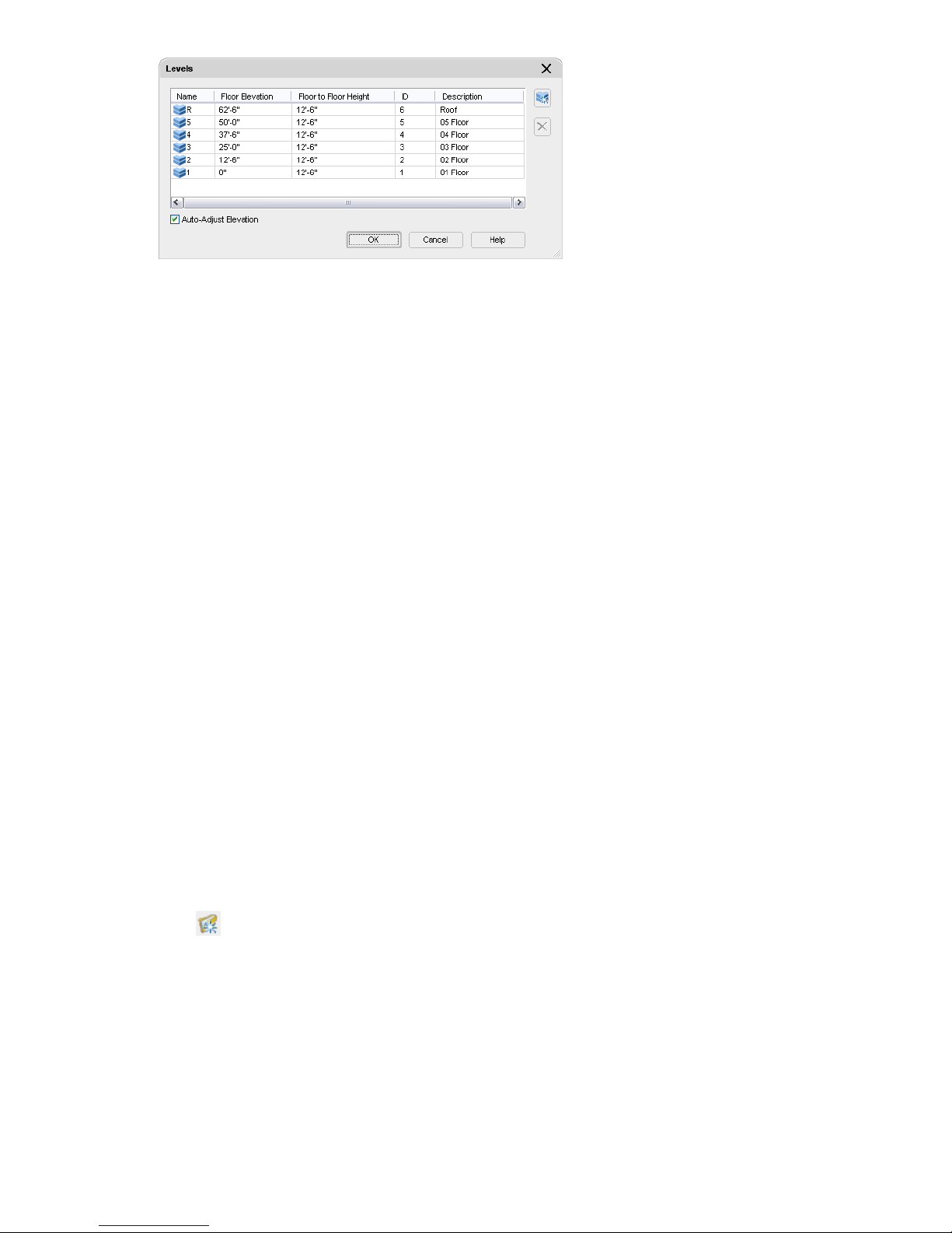
11 Click OK.
12 If you are prompted to regenerate views in the project, click Yes.
This ensures that the views are based upon the updated level information.
In this exercise, you added the levels for your building project. You defined the number of levels, their names, IDs, and
descriptions, their floor-to-floor heights, and their floor elevations. The name of the level is the unique identifier of
the level that is used when assigning constructs. The level ID can be used in schedules. You can add and remove levels
at any time during a project. The project is updated with the new level information.
Next, you create the categories that are used to organize all the project files you work with in this tutorial.
The structure of your project is set up. Next, you begin developing your building model.
Exercise 6: Categorizing Portions of Your Project
As you have seen, categories are sets of folders in a tree structure within a project that allow you to organize your project
files. At the highest level in this tree structure, each building project has a project folder, which bears the name of the
project. Within the project folder, there are four default folders: Constructs, Elements, Views, and Sheets. To help you
organize your building model data and reports, you can create categories and subcategories for constructs, elements,
and views. You can also organize the plotting sheets for your project by creating sheet subsets. This exercise shows how
to create the categories that are used to organize the project files for the Small Office Building project.
You can create categories and subcategories directly in the Project Navigator. You determine the number of categories
and subcategories, and the scheme for naming them, based on your project-specific needs. For this project, you create
construct categories by discipline: Architectural and Structural. Then, within each category, you create subcategories,
such as Building Outline, Partitions, and Shell, to hold the relevant constructs. You create some of these constructs as
you work through the exercises in this tutorial; others are added to the appropriate categories when you update your
project files.
The tree structure for the new project does not contain any construct categories or subcategories in which to place the
constructs that are added throughout this tutorial. This exercise shows how to create the two major construct categories
you use in this tutorial, Architectural and Structural, and how to add their subcategories.
Create categories for constructs
1 With the Project Navigator open, click the Constructs tab.
2 Select the Constructs folder.
3 Click at the bottom of the Constructs tab.
You can also right-click the Constructs folder, and click New ➤ Category.
4 Enter Architectural for the category name, and press ENTER.
56 | Chapter 2 Getting Started with Projects
Page 63
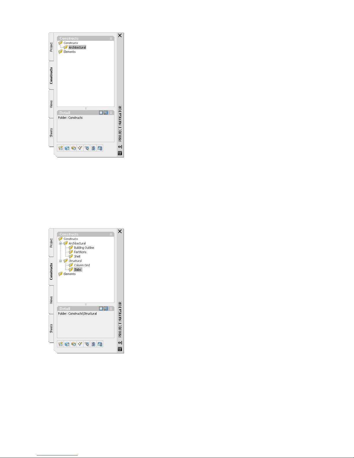
The Architectural subcategory under the Constructs category
5 Follow the same process to add another category under Constructs, and enter Structural for the name of the
category.
6 Select the Architectural folder, and add a category named Building Outline.
7 Add two more categories under Architectural, and name them Partitions and Shell.
8 Select the Structural folder, and add a category named Column Grid.
9 Add another category under Structural, and name it Slabs.
10 Verify that the Constructs categories are correct:
11 To make changes, you can move, rename, or delete a category:
■ Move a category by dragging it to a new location.
■ Rename a category by clicking the current name, and then clicking it again to enter a new name. You can also
select the category, right-click, and click Rename, and enter the new name.
■ Delete a category by selecting the category, pressing DELETE, and clicking Yes to confirm the deletion. You
can also select the category, right-click, and click Delete, and click Yes to confirm the deletion.
Lesson 2: Setting up Your Project Template | 57
Page 64

NOTE: If you rename, move, or delete a category that contains constructs or elements, or if you change the name or
location of individual constructs and elements, you change the external references within your project. If you make name
and location changes, you need to update the external references throughout the project by clicking the Repath Xref
icon ( ) at the bottom of the Constructs tab. If you make name or location changes and do not re-path the project,
the software prompts you to re-path when you switch to a different project.
Although you can create subcategories under the Elements category, they are not needed for the Small Office
Building project because it uses only one element. Next, you create categories for views.
Create categories for views
12 Click the Views tab.
13 Select the Views folder, and add a category named Exterior.
14 Add another category under Views, and name it Interior.
15 Verify that the Views categories are correct:
16 If you need to make changes, refer to step 11.
Exercise 7: Creating a Project from a Project Template
In this exercise, you create a new project for the office building type by using your project template.
Create a commercial office project
1 Click .
2 On the Add Project worksheet, specify the following information:
■ Enter OFF101 for Project Number.
■ Enter Commercial Office for Project Name.
■ Enter Project created from your template for Project Description.
3 Select Create from template project.
4 Browse to my documents\autodesk\my projects\small office building and select Small Office Building.apj.
5 Click OK twice. A new project is created and it is ready for the design phase as it has configured standards, a project
Content Browser library and project tools for the office building type.
58 | Chapter 2 Getting Started with Projects
Page 65

Exercise 8: Creating the Core and Shell from a Sketch Using Tools
In this exercise, you use the linework sketches that you added to the project in a previous exercise to create the typical
building core element and shell construct. It is not required that you start with a line drawing, but this technique shows
how you can leverage your existing AutoCAD skills and move quickly from a line drawing to generic or fixed object
styles. The fixed object styles are the ones that you would be appropriate for schedules. As you proceed with the design
you are moving from the general to the specific. For this exercise you can use the Small Office Building project.
Draw walls
1 With the Project Navigator open, click the Constructs tab.
2 Under Elements, double-click X_Sketch_Typical_Core_I.
This is the element drawing that contains the core sketch.
NOTE: If you do not see this drawing under Elements in the Project Navigator, you may have to copy it from the Small
Office Building project structure.
3 In the left viewport, zoom in around the first room on the left side of the core plan. In the next steps, you trace
over the outline of the room to add walls.
4 Move your cursor over the tool palettes set title bar. If Auto-hide is on, the tool palettes set will expand.
The tool palettes set, where you access the tools that you use to create your drawing, is organized into
function-specific palettes containing the tools.
5 Move your cursor off the tool palettes set and into the drawing area. If Auto-Hide is on only the palette bar displays.
6 The tool palettes set minimizes so that only the palette title bar is displayed. You may find that minimizing the
palettes set is helpful when you are working in the drawing area, or you display the full palettes set by clicking
Auto-Hide .
7 Move your cursor back onto the tool palettes set, click the stacked tabs to display the list of available palettes, and
click Design.
The tabs ''stack'' at the bottom of the tool palettes set when there are more tool palette tabs than can be displayed
within the current height of the tool palettes set. The list that is displayed when you right-click on the tabs shows
all available palettes in the group. The tab names displayed below the line on the list are the ones that are hidden
in the stack.
8 Right-click on the tool palettes set title bar and select Design.
9 Click the Wall tool on the top left of the palette.
10 Move your cursor over the Properties palette.
On the Design tab, verify the Style is Standard and select Left for Justify.
11 Use an Endpoint Osnap and start in the upper left corner.
Lesson 2: Setting up Your Project Template | 59
Page 66

12 Draw in a clockwise direction and pick the remaining corner points, closing on your start point.
13 Click in the right viewport and zoom in on the new walls.
14 Select the new walls and press Delete.
Convert the core plan sketch linework to walls
15 Click the left viewport, and zoom to extents.
16 On the Design tool palette, select the wall tool, right-click, and click Apply Tool Properties to Linework.
17 Use a crossing selection to select all of the floor plan linework.
18 Accept the default, No, to retain the layout geometry linework.
19 With walls still selected, on the Properties palette, under Dimensions, change the Base Height to 11’-9” and select
Left for Justify.
60 | Chapter 2 Getting Started with Projects
Page 67

20 Press ESC.
View the new walls in the right viewport.
21 In the left viewport, zoom in on the left side of the floor plan.
Use project tools
22 Right-click on the tool palette bar and select Commercial Office.
TIP: If you had a project group but were unable to see it listed that would be because the project group contains no
palettes. By default, in a new project, you have a project group and a project tools palette with a link to Help. Drag any
palette onto an empty group and it will be listed when you right-click on the tool palette bar.
23 With the Commercial Office palette group active, right-click on the palette bar and select New Palette.
24 Enter MOST USED for the new palette name.
25 On the Project Navigator, click the Content Browser icon.
26 From the appropriate categories, drag the wall style CMU-8 and the door style Hinged-Single onto your MOST
USED palette.
27 Click CMU-8, right-click, and then click Apply Tool Properties to Wall. These styles are from your project standards.
28 Select the four interior walls you selected previously.
29 Press ENTER. The selected walls now have the CMU-8 style applied to them.
30 Press ESC.
Lesson 2: Setting up Your Project Template | 61
Page 68

31 Right-click on the tool and select Properties to confirm that the tool is delivering a style from project standard
object styles.
Draw doors using dynamic dimensions
32 You create three doors 6” from the room corners beside the stair shaft.
On the Design palette, click the Door tool. Walls are generally drafted with Osnaps, so that you are making sure
that walls meet precisely. For placement of doors, windows and openings you can turn off OSNAP, ORTHO, POLAR,
OTRACK but leave DYN on.
62 | Chapter 2 Getting Started with Projects
Page 69

33 Select the wall segment, then use the TAB key to change focus to the dimension you want to be active. When you
have the dimension to the left of the door, enter 6. You control the door swing direction with the location of the
cursor as you place the door but you can also easily change this at any time with grips.
34 Repeat steps 32-33 to place a door on the hatched wall.
35 Repeat steps 32-33 for a third door but specify 12” from the corner. You placed three generic doors. In a schedule
they would list as “Standard.”
Replace generic doors with doors of a fixed style
36 With the Commercial Office palette active, on the MOST USED palette, right-click Hinged-Single, and click Apply
Tool Properties to ➤ Door. Then, select all three doors.
37 With the three doors selected, in the Properties palette, select the Standard size closest to 3’-0” x 6’-10”. Generic
or standard doors had user defined sizes but fixed style doors have a listing of manufactured sizes. They also have
materials assigned, so as you refine a design from standard styles to fixed styles the information and representation
of the objects is more exact. If you know what the finished components are then you can bypass the use of the
generic styles. Styles are easily changed at any time.
Grip edit the doors
38 Click on a door and click grips to make changes. Tool tips explain the function of the grips. Change the door
swings to match the illustration - with exit doors opening outwards. The grips let you change location, size, and
direction. The grey lines that appear on selection of the size grip, show the manufactured widths available for the
door style.
Lesson 2: Setting up Your Project Template | 63
Page 70

Reposition existing doors, windows or openings
39 The location of doors, windows and openings are easily changed. One drafting technique is to place multiple doors
approximately, then define style and location by editing each. Select the door on the right and right-click.
40 Select Reposition Along Wall.
41 Running Osnaps should be off. Click to select the line of placement on the door (left end) then use an End Osnap
to select the corner of the room.
42 Enter 3’ for the distance.
TIP: You can right-click on a wall, select AEC Dimension and place a dimension string that updates as walls, doors,
opening are edited. In some situations this may be useful as you can see the dimensions change with every edit. Delete
the dimension when finished. Dimensioning would typically be created in a View drawing.
Create an opening using offset/center
43 Click on DYN. Dynamic dimensions are off.
44 As an alternative to dynamic dimensions, in the Properties palette, you can change Position along wall from
Unconstrained to Offset\Center.
45 On the Design palette, click Opening.
46 In the Properties palette, change Width to 4’4 and Height to 7’. Change Position along wall to Offset\Center and
enter 2’ for Automatic offset. Without using Osnaps, this lets you place objects a specified distance from a corner
or opening and if you click near the middle of a wall segment, centered. You only need to pick close to the end,
opening, or center of a wall segment to get precise placement. Osnaps are not needed.
47 Place all four elevator openings.
64 | Chapter 2 Getting Started with Projects
Page 71

Convert remaining linework to walls
48 Zoom to extents, and select all the small rectangular shapes above the diagonal line in the drawing.
49 Click the diagonal line.
50 On the Design tool palette, click the Wall tool and select Apply Tool Properties to ➤ Linework.
51 In the Properties palette, change the Height to 11’9. Change the style to W2 and Justify to Left. These styles are
already in the drawing so they list as an option in the Properties palette.
TIP: Linework has a beginning and end, so it has a direction. In this case it is known how the linework was drafted so it
is possible to predict which side of a line a left-justified wall will be placed. If you plan on using linework sketches you
would establish some rules as to drawing direction so that placement is predictable.
52 Repeat for the circles below the diagonal line but select the style col_covers, set Justify to Center and Base height
to 11’9”.
53 Turn off the layers SKETCH and SKETCH LOCKED.
54 Close and save the drawing.
Open the drawing for the building shell and create walls and curtain walls
55 Double-click the construct X-Sketch_01 Floor Shell_I.
NOTE: If you do not see this drawing under Constructs in the Project Navigator, you may have to copy it from the Small
Office Building project structure.
56 Right-click on the tool palettes set title bar, and click Design. On the Design palette, right-click on the curtain wall
tool and select Apply Tool Properties to ➤ Referenced Base Curve.
57 Click one of the two green polylines to convert to a curtain wall.
Lesson 2: Setting up Your Project Template | 65
Page 72

58 In the Properties Palette, change Base height to 12’6 (Floor to Floor Height). This standard curtain wall is already
in the drawing with assignments of doors for an infill panel.
TIP: To make any object available in a drawing, you can use a tool to create the object and the style is saved within the
drawing. The placed object can be deleted but the style definition still resides in the drawing. This is one technique to
introduce material styles. If you place a door with an ash material then the material style is introduced with the door.
59 Repeat steps 56-58 to convert the other green polyline to a curtain wall.
60 On the Design palette, right-click the Wall tool and select Apply Tool Properties to ➤ Linework.
61 Select the remaining yellow linework, and press ENTER.
62 Enter y to erase the linework.
63 In the Properties palette, change the style of the walls to Brick-exterior and the Base height to 12’6.
64 Zoom in closely to the curved curtain wall and click on the underlying curved polyline.
65 Click to select the middle location grip and move it outwards.
The curtain wall updates to reference the new base curve.
66 Enter u until the curtain wall returns to its original position.
67 Close and save the drawing.
Reference the element to the construct
68 In the Project Navigator, click the Constructs tab.
69 Drag the element icon X-Sketch Typical Core_I onto the X-Sketch_01 Floor Shell_I.
70 Double-click the construct X-Sketch_01 Floor Shell_I to open the drawing and confirm you have a service core
element (reusable on other floors) within the building shell for floor 01.
66 | Chapter 2 Getting Started with Projects
Page 73
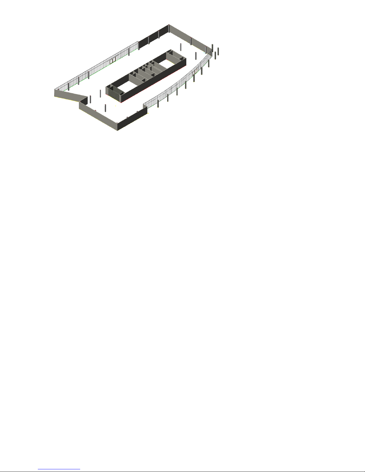
71 Close and save the drawing.
In this lesson, you explored project structure looking at categories and the drawing types (elements, constructs, views
and sheets) that together constitute a project. You added a palette and tools to your default tool palettes from the
Content Browser. You then created a project and refined it for use as a project template. That project template included
project standard styles and project tools that deliver the project-specific object styles to your drawings. You defined
the levels for your building model and added categories to the project. By defining levels, you established the values
that are used to “assemble” the building model when you create views later. The categories and subcategories you
created are folders within the project folder that are used to organize the drawings that make up your project. These
folders hold the constructs and views that you create directly in the Project Navigator, or that you add. You added
legacy drawings for use in the exercises, just as you would add drawings from a consultant or because you wish to
include regular AutoCAD files and you quickly converted linework to a drawing with walls, doors, openings and curtain
walls.
Categories help you organize your project files, whether they are constructs, elements, views, or sheets. Categorizing
constructs also gives you additional labels for the constructs that can be used when generating views. When you create
views of your building data, you can use categories as a selection criterion. For example, for a complete view of all
framing constructs in your building, you could set up a view that references the Framing subcategory, thereby referencing
all drawing files from that category. If you add more framing drawings to the Framing category later, the view is updated
automatically when you regenerate it. You can organize the plotting drawings for your project by creating sheet subsets
in the Sheet Set View. Using construct categories in this way can help ensure that all members of a project team reference
the proper files.
The structure of your project is set up. Next, you add manage project standards.
Lesson 3: Managing Project Standards
In this lesson, you manage the object styles that are now a project feature. Both tutorial datasets include configured
standards. The dataset used for this chapter is the Steel-Framed Residence. You version all the project styles, and then
manage the changes.
Exercise 1:Versioning,Validating, and Updating Project Styles and Definitions
In this exercise, you create a new version of the project standard styles, manually validate an individual drawing against
the standards so you can see how the feature works, validate all styles in all project drawings simultaneously, and
update all project drawings so they have the latest versions of all the object styles.
Project standards are a major time-saver as they provide you with a way to manage project standards in one location
and apply them to project drawings. How the standards should be configured and applied is a decision for your CAD
Manager. Be sure to consult with him or her regarding the process that is the best fit for your organization.
Lesson 3: Managing Project Standards | 67
Page 74
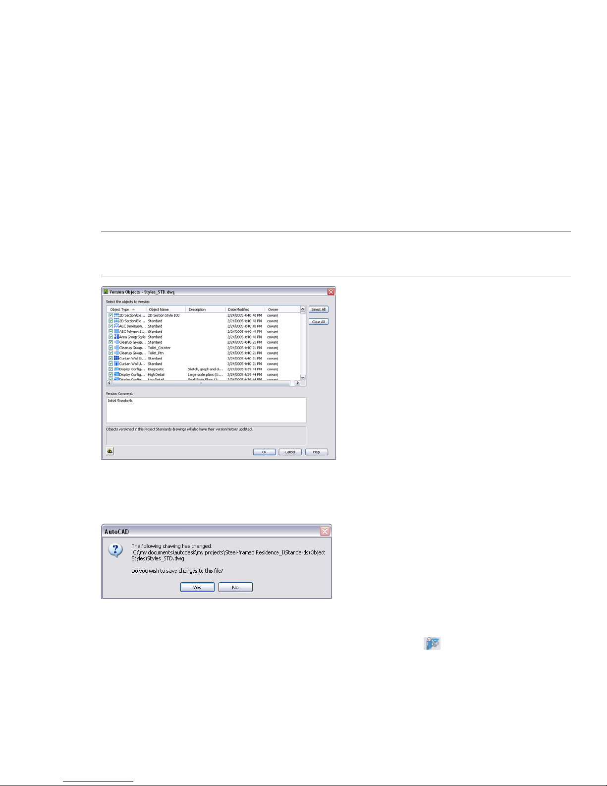
Open the Steel-Framed Residence_I project
1 On the File menu, click Project Browser.
The Project Browser is displayed.
2 Double-click Steel-Framed Residence_I.
The bulletin board and the project information in the browser updates for the project.
3 Click Close to exit the Project Browser.
Use the Style Manager to apply a version to project object styles
4 On the Format menu, click Style Manager.
5 In the tree view, expand the project standard icon for STL101-Steel_Framed Residence_I.
6 Expand the standards file, Styles_STD.dwg.
7 Right-click the standards file (Styles_STD), and select Version Drawing.
8 Click in the Version Comment field, and enter Initial Standards.
NOTE: Versioning is done automatically when you configure project standards for a new project. The reason you are
doing it now is to create a new version of the standard styles in the existing project. This will allow you to validate against
the latest version of standard styles and see how validation and updating works.
9 In the Version Objects dialog box, click OK.
10 In the Style Manager, click OK.
11 Click Yes to save the change to your standards.
Decide how to apply the validation
12 On the Project tab of the Project Navigator, click Configure Project Standards . The Configure AEC Project
Standards dialog box opens.
13 Click the Synchronization tab.
14 Select Manual.
15 Click OK to exit the dialog box.
68 | Chapter 2 Getting Started with Projects
Page 75
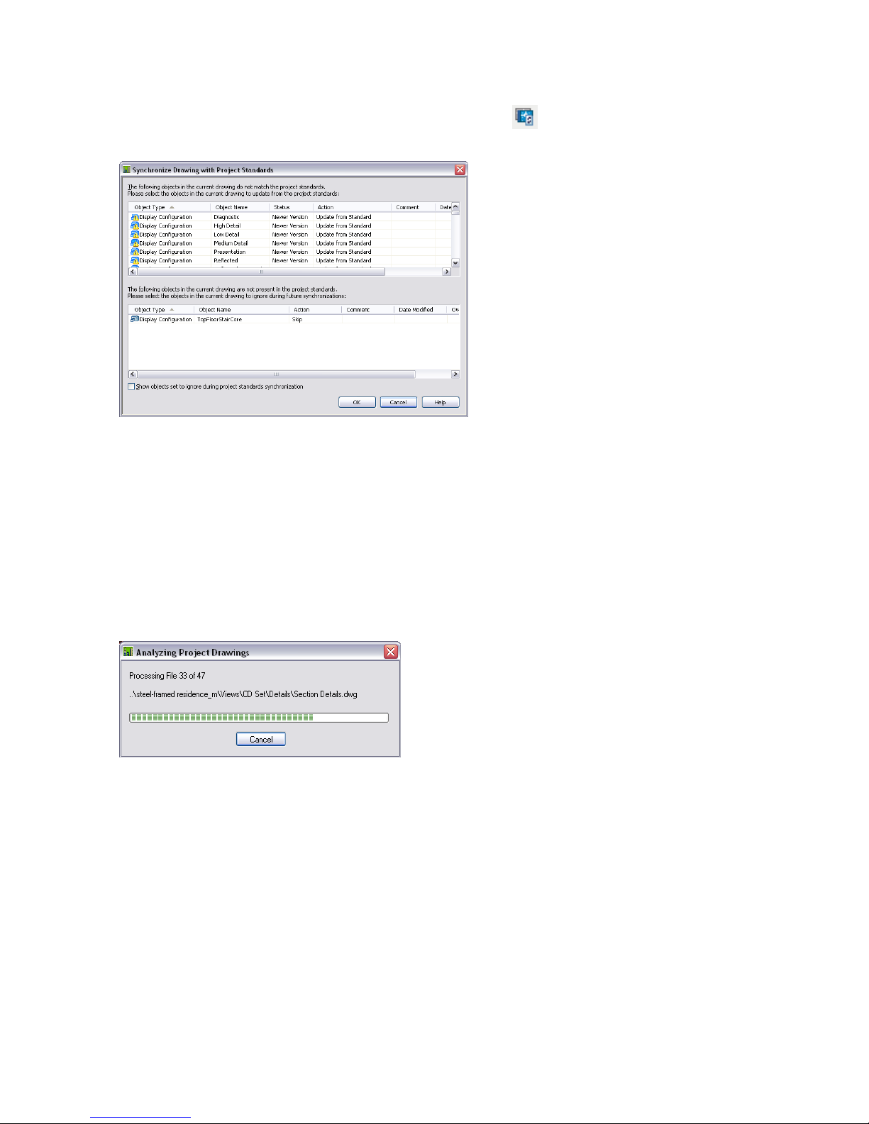
Validate manually
16 In the Constructs tab, double-click to open any construct.
17 On the AEC Project Standards toolbar, click Synchronize Drawing .
18 Select Synchronize Drawing. The Synchronize Drawing with Project Standards dialog box opens.
19 Review the dialog box. You have older versions of styles in your current drawing because you applied a version to
the standards today. You could change the Action field to keep any old versions of styles, should you want them.
You will update them from the standards.
20 Leave the Action item at Update from Standard and click OK.
Validate and Update object styles in all project drawings
21 If you do not see CAD Manager menu on the Menu bar, on the Window menu, click Pulldowns ➤ CAD Manager
Pulldown.
22 On the CAD Manager menu, click AEC Project Standards ➤ Synchronize Project with Standards to update all your
project drawings. The Analyzing Project Drawings dialog box opens and runs the validation against all project
drawings. The progress is reported in a dialog box.
23 The Synchronize Project with Project Standards dialog box opens. The top portion identifies non-compliant styles
in project drawings. The bottom portion identifies any styles in the project drawings that do not exist in your
standards.
Lesson 3: Managing Project Standards | 69
Page 76

24 Click OK to accept the default settings, updating the project drawings from the standard styles and skipping styles
in the current drawing that are not standard. Skip ensures they are listed with validation while Ignore drops them
from the list.
25 The Synchronizing Project dialog box opens and the changes are completed.
26 On the Window menu, click Close All. The AutoCAD dialog box opens.
27 Click Yes to save changes. Changes are not made until the files are saved. You will not see changes in view drawings
or sheets until the changes are saved.
Exercise 2: Modifying a Standard Style and Updating the Project
The purpose of this exercise is to show that, while working on project drawings, styles can be edited, uploaded to the
standard files and subsequently applied to all project drawings. The example chosen is visual so you can see the style
changes. A material definition called “paint” which has a red material image is changed to a white paint image. By
updating project drawings all the structural members having the paint material are changed to a white paint finish.
Open the Steel-Framed Residence Project
1 On the File menu, click Project Browser.
2 Double-click Steel-Framed Residence_I.
3 Click Close to exit the browser.
4 On the Constructs tab, double-click House Structure to open it in the drawing area.
Edit a material definition on a structural member
5 Right-click a column in the drawing.
6 Click Edit Member Style.
The Structural Member Style Properties - Column W8x31 dialog box opens.
7 On the Material tab, click the Edit Material button.
The Material Definition Properties - Paint dialog box opens.
8 Click the Edit Display Properties button.
9 Click the Other tab, and select the Render Material drop-list.
70 | Chapter 2 Getting Started with Projects
Page 77
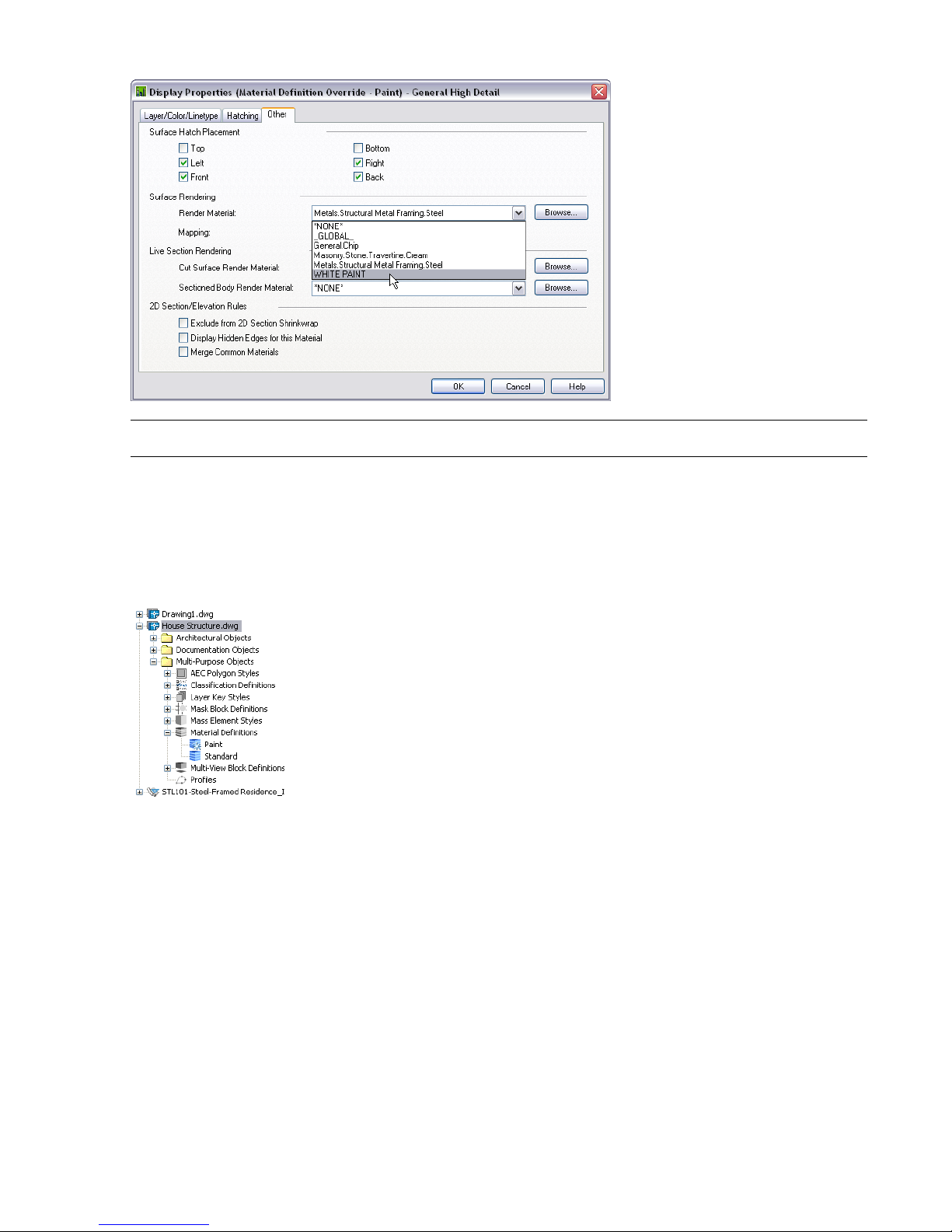
10 Under Render Material, select WHITE PAINT.
NOTE: You changed the material for the High Detail display representation.
11 Click OK three times.
Use the style manager to update the standards with the edited style
12 On the Format menu, click Style Manager.
13 Expand the House Structure, Multi-Purpose Objects category.
14 Expand Material Definitions. The star on the paint definition indicates it is newer than the standard.
15 Right-click Paint.
16 Select Update Standards from Drawing. The Update Project Standards dialog box opens.
Lesson 3: Managing Project Standards | 71
Page 78
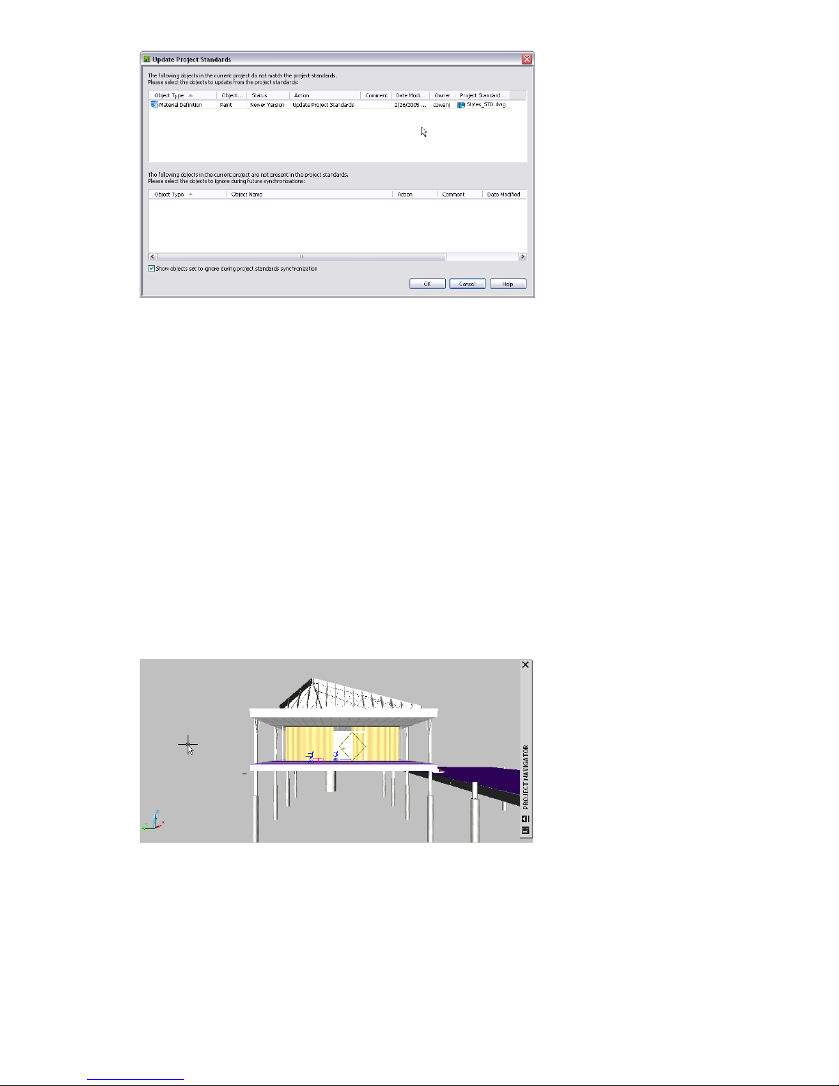
17 Click OK. The dialog box opens to complete the update.
The star icon which indicated a newer version, has returned to normal.
18 Click OK.
19 Click Yes to save the changes to the standard file.
Update all project drawings
20 On the CAD Manager menu, click AEC Project Standards ➤ Synchronize Project with Standards.
The Analyzing Project Drawings dialog box opens, and then the Synchronize Project with Project Standards.
21 Click on the Action column header to change the order of listing. You should be able to see material paint style
and the host drawings that are to be updated.
22 Click OK.
Confirm the material style changed in other drawings
23 On the Constructs tab of the Project Navigator, open other drawings to confirm the structural members have
changed from a red finish (Materials.Structural Metal Frame.Steel) to a white paint.
24 On the Views tab, expand the Model category.
25 Double-click on any of the model category views to see that the structural steel has had its material changed to
white paint.
26 Save the drawings.
In this exercise you made a change to a style, while in a project drawing, updated project standards with the revised
material style and applied the style to all project drawings.
72 | Chapter 2 Getting Started with Projects
Page 79

Developing Your Building Model
Design
3
Autodesk® Architectural Desktop provides three-dimensional (3D) design objects, such as walls, doors, slabs, and
stairs, for you to use in creating a building model. These objects are organized as tools on palettes. Design objects
have several inherent graphical representations, allowing them to be depicted in different views such as a reflected
ceiling representation or with detail as appropriate for a high detail plan view. You can also control how the
component parts of an object, such as a door jamb or door swing, display on your screen.
In this part of the tutorial, you use tools to develop your building model design, and you use the Project Navigator
to create and edit various constructs and elements within your project. The tool palette, specific to the small office
building project, contains the basic object tools needed to complete these lessons.
73
Page 80

Lesson 1: Designing the Building Shell
In part 2 of this tutorial, you used the Project Navigator to set up the structure of your project. In part 3, you work in
the Project Navigator to create constructs for your building model. In part 4, you create construction drawings and
schedules from the model.
This lesson focuses on adding and modifying curtain walls to complete the building shell. Curtain walls have components
such as a frame and infill panels. A curtain wall is made up of grids for the frames, which have horizontal and vertical
divisions.
Exercise 1:Adding a Curtain Wall
This exercise shows one way to add curtain walls to a drawing using a curtain wall tool. A preliminary building shell
for one floor is provided. The shell consists of exterior brick walls. Using the curtain wall tool on the Tutorial tool
palette, you convert two of the exterior brick walls to a curtain wall. You adjust the length of the converted curtain
wall to match a referenced outline of the building.
IMPORTANT: This exercise uses project Small Office Building_I. If you have already extracted the dataset and set it as your
current project, you can continue with this exercise. If you have not extracted the dataset, do so before beginning this exercise.
For step-by-step instructions, see Extracting Datasets .
Convert a wall to a curtain wall
1 With the Project Navigator open, click the Constructs tab.
2 Under Elements\Exercises, double-click X-Adding a Curtain Wall to open it in the drawing area.
The shell was drawn with a wall style.
3 On the Small Office Building palette group, click the Curtain Wall Styles tab.
4 Right-click the Tutorial-Curtain Wall tool, and click Apply Tool Properties to ➤ Walls.
5 At the top of the drawing, select the long rear exterior brick wall and the adjoining angular wall, and press ENTER.
6 Enter b (Baseline) to align the curtain walls along the baseline of the existing walls, and press ENTER.
7 Enter y (Yes) to erase the layout geometry (the walls), and press ENTER.
8 Press ESC to exit selection mode and turn off the wall grips.
The exterior brick walls are converted to curtain walls.
To verify that your walls are located properly, you can reference in a construct or element. In this case, the 01
Building Outline construct provides the verification you need.
Reference the building outline into the ground floor shell
9 On the Project Navigator under Constructs\Architectural\Building Outline, right-click 01 Building Outline, and
click Xref Overlay.
The building outline runs along the exterior edge of the brick walls and the interior edge of the curtain wall. The
connection needs to be adjusted to match the following illustration.
74 | Chapter 3 Developing Your Building Model Design
Page 81

10 Using and on the Zoom flyout on the Navigation toolbar, zoom in to the left end of the new curtain wall
to view it with the referenced building outline.
The building outline runs along the interior edge of the curtain walls.
Review the curtain wall
11 Click on the Zoom flyout on the Navigation toolbar, and zoom in to the area around the left end of the new
curtain wall.
The curtain wall frame members overlap.
Unlike other wall objects in Architectural Desktop, curtain walls do not clean up automatically when they intersect
other walls. Typically, when adding curtain walls that intersect, you apply an edge condition or miter the walls to
join the curtain wall segments.
12 Click on the Zoom flyout on the Navigation toolbar to zoom to the extents of the drawing.
13 Click on the Zoom flyout on the Navigation toolbar, and zoom in to the area around the right end of the new
curtain wall.
Notice that the curtain wall and wall are misaligned. You want the connection shown in the second illustration,
where the interior of the curtain wall is flush with the end of the brick wall.
Existing condition
Lesson 1: Designing the Building Shell | 75
Page 82

Corrected condition
14 Click the curtain wall.
15 Click the lengthen grip and move it to the outline or outside of the brick wall.
The lengthen grip maintains the wall segment orientation.
16 Press ESC to exit grip mode.
17 Click the brick wall.
18 Click the lengthen grip and move it back to the outline.
19 Press ESC.
Detach the building outline xref
20 In the drawing area, select the building outline, right-click, and click Xref Manager.
You can also click at the bottom right of the drawing area to display the Xref Manager dialog box. This icon
is displayed only when xrefs exist in the current drawing.
21 In the Xref Manager dialog box, select 01 Building Outline, and click Detach.
22 Click OK.
The building outline is no longer referenced into the first floor shell.
23 Save the X-Adding a Curtain Wall drawing.
In this exercise, you referenced a project drawing to check alignment of building components. You added a curtain
wall to the ground floor building shell using the curtain wall tool and adjusted components using the lengthen grip.
Next, you add an entrance to the front of the building.
Exercise 2:Adding an Entrance Using a Tool
This exercise shows how to add an entrance to the front of the building with a door/window assembly tool, and how
to change the door swing using grips.
Add a front entrance
1 With the Project Navigator open, click the Constructs tab.
2 Open the exercise drawing.
■ If you completed the previous exercise, you can continue in the open drawing. Click on the Zoom flyout
of the Navigation toolbar to prepare for this exercise.
■ If you prefer to use a supplied drawing, double-click X-Adding an Entrance.
3 Click on the Zoom flyout on the Navigation toolbar, and zoom in to the area where the left end of the curved
wall segment meets the short wall segment.
76 | Chapter 3 Developing Your Building Model Design
Page 83

4 Right-click on any toolbar, and click Object Snap.
5 On the Door/Window Assembly Styles palette, click Tutorial-Entrance.
6 Select the curved wall.
7 Click on the Object Snap toolbar.
8 Click on the Object Snap toolbar to snap to an intersection.
9 Move the cursor over the intersection of the curved wall and the short wall segment at the exterior corner, and
select the Intersection snap point that displays.
10 Move the cursor to the right along the interior of the curved wall, enter 47', and press ENTER twice.
The entrance is added to the curved wall. By positioning the cursor on the interior of the curved wall, you add the
entrance with the doors opening inward. If you positioned the cursor on the exterior of the wall, the entrance
would be inserted with the doors opening outward.
Change the door swing
11 Zoom in to the area around the door/window assembly.
12 Select the door in the assembly to display its grips, and hover the cursor over the grips to display the Flip grip.
13 Click the Flip grip to change the door swing.
14 Right-click, and click Deselect All to turn off the door grips.
The door swing is flipped so that the doors open outward.
15 Save the drawing.
Lesson 1: Designing the Building Shell | 77
Page 84

In this exercise, you added an entrance to the front of the building using a door/window assembly tool, and then used
the Flip grip to reverse the door swing. Next, you add an entrance to the rear of the building, using a sketch as the basis
for creating a door/window assembly object.
Exercise 3: Creating an Entrance from a Sketch
This exercise shows how to make a simple door/window assembly to use as the entrance in the rear curtain wall. You
begin by merging cells in the curtain wall to form a larger cell (opening) for the entrance. Then, you use this opening
to sketch a design of the entrance, and convert the custom sketch to a window assembly. Later, you will add a door to
the window assembly, and insert the door/window assembly in the curtain wall using an override.
Add an opening in the curtain wall for an entrance
1 Open the exercise drawing.
■ If you completed the previous exercise, you can continue in the open drawing.
■ If you prefer to use a supplied drawing, double-click X-Creating an Entrance.
2 Click on the Views flyout on the Navigation toolbar.
3 Click on the Zoom flyout on the Navigation toolbar, and zoom in to the area around the curtain wall.
4 Click in the lower-right corner of the drawing area to turn off the surface hatch on the bricks.
5 Select the curtain wall, right-click, and click Infill ➤ Show Markers.
Displaying the cell markers makes selecting individual cells of the curtain wall easier.
6 Select the curtain wall, right-click, and click Infill ➤ Merge.
7 Locate the cell identified with the number 1 in this isometric view, and select its cell marker [ ].
The number 1 identifies this cell as the first one to be merged.
8 Select the cell marker to the right of the cell you just selected.
78 | Chapter 3 Developing Your Building Model Design
Page 85

The two cells are merged.
9 Press ENTER to repeat the last command.
10 Select the cell marker for the merged cell, and then select the cell marker to its right.
11 Repeat steps 9 and 10 five more times to merge a total of eight cells.
Sketch the linework for the entrance
12 Select the curtain wall, right-click, and click Isolate Objects ➤ Isolate Objects.
13 Click on the Views flyout on the Navigation toolbar to view the curtain wall in a back elevation view.
14 Select the curtain wall, right-click, and click Infill ➤ Hide Markers.
15 Click on the Shapes toolbar to draw a rectangle in the curtain wall opening.
16 On the Object Snap toolbar, click , and select the upper left interior corner of the larged merged cell in the
curtain wall.
17 Select on the bottom frame of the curtain wall below the lower right interior corner.
Lesson 1: Designing the Building Shell | 79
Page 86

18 In the rectangle, add seven vertical lines to represent the divisions of the window assembly 3 feet apart:
■ Right-click, and click Basic Modify Tools ➤ Explode.
■ Select the rectangle, and press ENTER.
The Explode command breaks a compound object (the rectangle) into its component objects (lines). You can
now select and use the individual line segments to continue creating the sketch.
■ Select the left vertical line of the rectangle, right-click, and click Basic Modify Tools ➤ Array.
■ In the Array dialog box, verify that Rectangular Array is selected.
■ Enter 1 for Rows.
■ Enter 8 for Columns.
■ Enter 0" for Row offset.
■ Enter 3' for Column offset.
■ Click OK.
19 Add one horizontal line 7 feet from the bottom of the rectangle.
■ Select the bottom line of the rectangle, right-click, and click Basic Modify Tools ➤ Copy.
■ Select the bottom line of the rectangle as the base point, and press ENTER.
■ Move the cursor up, enter 7', and press ENTER twice.
The sketch of the entrance is complete.
Convert the sketch to a window assembly
20 On the Door/Window Assembly Styles tool palette, right-click Tutorial-Entrance, and click Apply Tool Properties
to ➤ Elevation Sketch.
21 Working from left to right, draw a window selection box to select only the sketch, and press ENTER.
IMPORTANT: Use a window selection that includes only the linework you added. Do not use a crossing window, which
is drawn from right to left. If you use a crossing window, the curtain wall will be included in the selection set, and the
software will apply the properties of the door/window assembly tool to the curtain wall.
22 Select the bottom segment of the rectangle for the baseline.
23 Enter y (Yes), and press ENTER to remove the sketch from the drawing.
24 Right-click, and click Deselect All to turn off the grips.
The window assembly is created from the sketch, and the sketch is removed from the drawing. In your own work,
you may prefer to leave sketches in your drawings, so that they are available for modification later.
80 | Chapter 3 Developing Your Building Model Design
Page 87

25 Select the curtain wall, right-click, and click Infill ➤ Show Markers.
Save the design rules to a style
26 Select the door/window assembly which is currently Tutorial-Entrance, right-click, and click Design Rules ➤ Save
to Style.
27 In the Save Changes dialog box, click New.
28 In the New Door/Window Assembly Style dialog box, enter Custom for New Name.
29 Click OK twice.
30 Save all open project drawings.
In this exercise, you merged cells in the rear curtain wall to form a larger cell (opening), isolated appropriate geometry
in an elevation view, sketched an elevation view of a custom entrance, and used a tool to convert the sketch to a custom
door/window assembly. The custom door/window assembly was drawn in place but is not yet an infill component of
the curtain wall. Next, you add a door to complete the entrance, and modify the curtain wall to accept the custom
door/window assembly.
Exercise 4: Modifying a Curtain Wall
This exercise shows how to add a door to the custom door/window assembly you created in the last exercise, how to
save the door/window assembly to a style, and how to add the door/window assembly to the curtain wall as an infill
option and an override to a curtain wall cell.
Modify the window assembly elements to match the curtain wall elements
1 With the Project Navigator open, click the Constructs tab.
2 Double-click on the icon to open the exercise drawing.
■ If you completed the previous exercise, you can continue in the open drawing.
■ If you prefer to use a supplied drawing, double-click X-Modifying a Curtain Wall.
3 Select the window assembly, and move it above the curtain wall.
Lesson 1: Designing the Building Shell | 81
Page 88

The assembly created in the previous exercise was not inserted into the curtain wall. It was created in-place, using
the curtain-wall as a template for the sketch but it is not yet part of the curtain wall. You now isolate the assembly
for easier editing. After you modify the assembly, you save the door/window assembly style so it can be inserted
as an override to fill a cell in the curtain wall. The unanchored instance of the assembly can then be erased.
4 With the door/window assembly selected, right-click, and click Edit Door/Window Assembly Style.
5 Click Yes to edit the Door/Window Assembly Style.
6 In the Door/Window Assembly Style Properties dialog box, click the Design Rules tab.
7 In the left pane, click Frames.
8 In the lower right pane, enter 2" for Width, and enter 3" for Depth.
9 In the left pane, click Mullions.
10 In the lower right pane, enter 1.5" for Width, and enter 3" for Depth.
11 In the left pane, click Infills.
Notice that the double door optional infill, associated with the Tutorial-Entrance style, was copied into the custom
style when you applied the tool to the elevation sketch. You use the Double Door style as an override later in this
exercise.
12 Click OK.
The dimensions of the frames and mullions in the window assembly match those in the curtain wall.
13 Select the window assembly above the curtain wall, right-click, and click Infill ➤ Show Markers.
Displaying cell markers makes selecting individual cells in the window assembly easier.
Create a door opening in a window assembly
14 With the window assembly selected, right-click, and click Infill ➤ Merge.
15 Select the cell marker [ ] for the bottom cell that is fourth from the left, and then select the cell marker to the
right of it.
The two cells are merged to form an opening for a door.
16 Press ENTER to repeat the last command, and then merge the two cells above the door opening in the window
assembly.
TIP: Zoom in to select the cell markers, if necessary.
Add a door to the window assembly
17 Select the window assembly, right-click, and click Infill ➤ Override Assignment.
18 Select the cell marker for the merged cell on the bottom, and press ENTER.
82 | Chapter 3 Developing Your Building Model Design
Page 89

19 On the Infill Assignment Override worksheet, specify the properties:
■ Select Double Door for the Infill Element Definition.
Because the Tutorial-Entrance tool you used to convert the sketch has a double door defined as an infill in its
style, the Double Door infill is displayed on this list.
■ Under Frame Removal, select Bottom to remove the bottom frame of the window assembly where the door is
being added.
■ Click OK.
20 Select the door/window assembly, right-click, and click Infill ➤ Hide Markers.
The door is added to the door/window assembly.
Save the door/window assembly as a style
21 Select the frame of the door/window assembly, right-click, and click Design Rules ➤ Save to Style.
22 On the Save Changes worksheet, select Transfer Merge Operations to Style and Transfer Infill Overrides to Style.
23 Click OK.
The custom door/window assembly style is added to the Style Manager, where it is available for use in other
drawings. Before you can insert the door/window assembly as an override to the cell in the curtain wall, the assembly
must be assigned as an infill option for the curtain wall.
Specify new door/window assembly as an infill option for the curtain wall
24 Select the curtain wall, right-click, and click Edit Curtain Wall Style.
25 In the Style Properties dialog box, click the Design Rules tab.
26 In the left pane, click Infills.
27 Click to add a new infill.
28 Specify the properties for the infill:
■ Enter Tutorial-Entrance for Name.
■ Select Style for Infill Type.
■ Expand Door/Window Assembly Styles, and select Custom.
■ Click OK.
Lesson 1: Designing the Building Shell | 83
Page 90
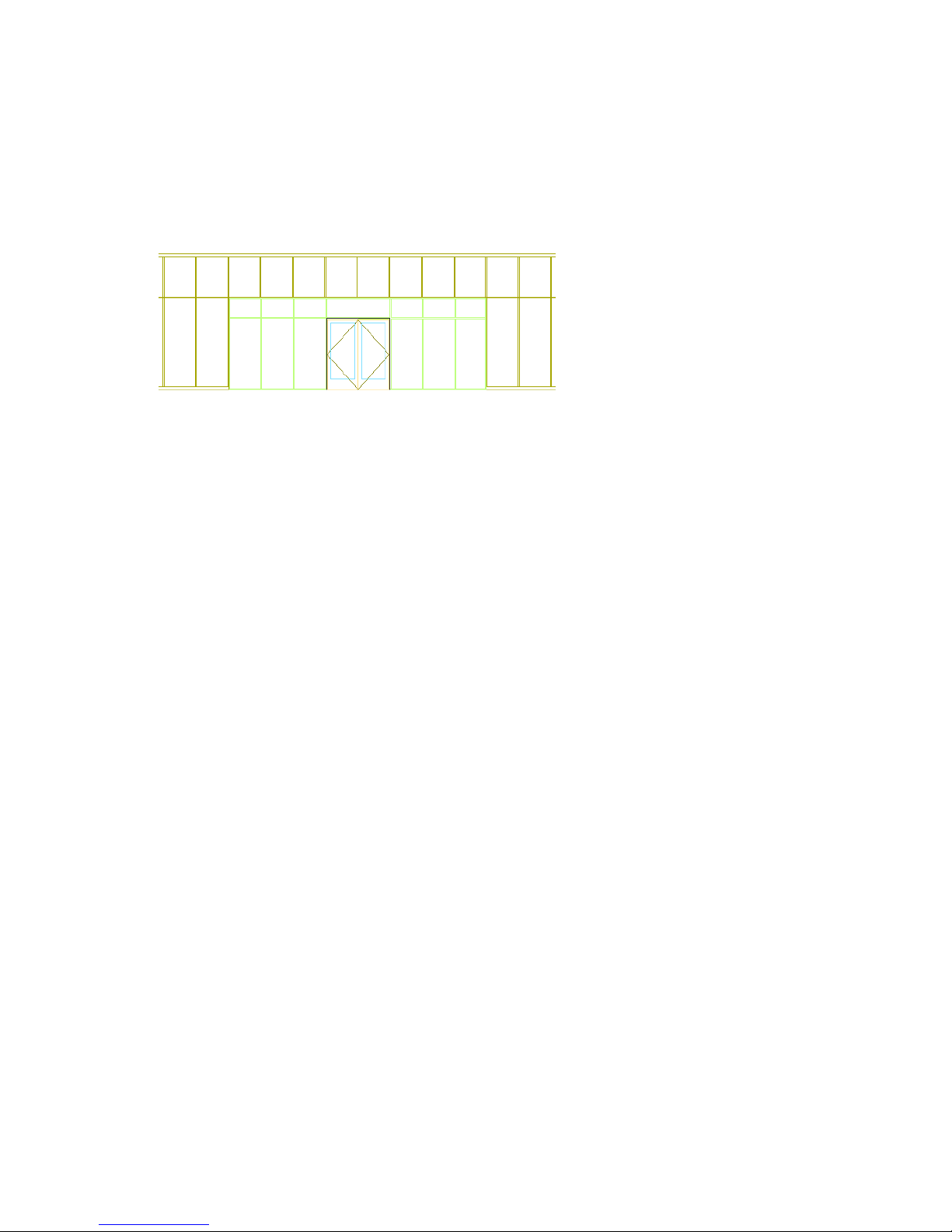
Assign an override to insert the door/window assembly
29 Select the curtain wall, right-click, and click Infill ➤ Override Assignment.
30 Select the cell marker for the merged cell, and press ENTER.
31 On the Infill Assignment Override worksheet, select Tutorial-Entrance for Infill Element Definition.
32 Under Frame Removal, select Bottom to remove the bottom frame of the curtain wall from where the door/window
assembly is being added, and click OK.
The door/window assembly is inserted in the curtain wall.
33 Select the curtain wall, right-click, and click Infill ➤ Hide Markers.
Markers for the curtain wall and the door/window assembly can be turned on and used to make modifications to
the completed curtain wall. You can also use grips to edit the curtain wall.
34 Select the door/window assembly above the curtain wall, right-click, and click Basic Modify Tools ➤ Erase.
35 Save all open project drawings.
In this exercise, you added a door to the custom door/window assembly, and saved the door/window assembly as a
style in the Style Manager. You also added the new entrance to the curtain wall as an infill option and an override to
a curtain wall cell.
In this lesson, you added and modified curtain walls to complete the building shell. You began by converting exterior
brick walls to curtain walls in the rear of the building and adding an entrance to the brick wall using a door\window
assembly tool. Then, you created a custom door/window assembly as an entrance for the rear curtain wall. You did this
by applying the properties of a window assembly tool to a sketch and adding a door. You added the custom door/window
assembly as an infill option for the curtain wall style and used it as an override to a curtain wall cell. Next, you create
floor slabs and roof slabs, and then begin laying out the interior building space.
Lesson 2: Laying out the Building Core
This lesson shows how to create floor slabs and roof slabs, and how to add interior partitions. Once the partitions are
in place, you modify the surface of a wall by adding pilasters.
Exercise 1: Creating Floor and Roof Slabs
One way to develop the floor and roof of the building is to use the two-dimensional (2D) building outline. You can
use a closed polyline, such as the building outline, to extrude a floor slab and roof slab by applying the Slab tool to the
polyline.
A slab is a three-dimensional (3D) body bounded by a planar polygon (perimeter) of any shape. The body of a slab is
defined by an extrusion perpendicular to the plane of the perimeter. You can use slabs to draw floors and other objects
that require a flat surface, such as a roof. You can customize slab edges by adding fascia and soffits to define edge
conditions, such as a cant or curb. When you extrude a closed polyline to create a slab, the first line drawn in the
polyline becomes the baseline edge of the slab.
84 | Chapter 3 Developing Your Building Model Design
Page 91

This segment of the polyline was drawn first, so it becomes the baseline edge of the slab
Create the Floor Slab construct
1 With the Project Navigator open, click the Constructs tab.
The finished slab constructs are provided so you can view the completed project. You recreate the drawings in an
exercise file (prefix X#-).
2 Create the X-01 Floor Slab construct by copying and renaming the 01 Building Outline construct:
■ On the Constructs tab under Constructs\Architectural\Building Outline, right-click 01 Building Outline, and
click Copy.
■ Under Constructs\Structural, right-click Slabs, and click Paste.
■ Under Slabs, right-click 01 Building Outline, and click Properties.
■ On the Modify Construct worksheet, enter X-01 Floor Slab for Name.
■ Enter Floor Slab 1st Floor for Description.
When you click to enter a description, a separate editing window opens. Enter the descriptive text, and click
OK.
■ Under Assignments, verify that only Level 1 is selected for the location in the building.
■ Click OK.
The X-01 Floor Slab construct is added under Slabs.
3 Double-click X-01 Floor Slab to open it in the drawing area.
Lesson 2: Laying out the Building Core | 85
Page 92

Generate the first floor slab
4 On the Slab Styles tool palette, right-click Tutorial-Slab, and click Apply Tool Properties to ➤ Linework and Walls.
5 In the drawing area, select the building outline polyline, and press ENTER.
6 Enter y (Yes) to erase the layout geometry, and press ENTER.
7 Enter d (Direct) for Creation mode, and press ENTER.
8 Enter t (Top) for Justification, and press ENTER.
9 View the slab properties.
If the Properties palette is not open, double-click the slab to open the Properties palette.
10 Verify that the slab is on layer A-Slab.
You are using the AIA layer key style provided with the software which assigned the slab object to the correct layer
when it was created.
11 On the Properties palette, under Dimensions, enter 10" for Thickness.
12 Under Location, enter -10" for Elevation.
This elevation drops the slab and places the top of the slab at floor level.
13 Right-click, and click Deselect All to turn off the grips
Create the X-02 Floor Slab construct
14 Create the X-02 Floor Slab construct by copying and renaming the Typical Building Outline construct:
■ On the Constructs tab, under Constructs\Architectural\Building Outline, right-click Typical Building Outline,
and click Copy.
■ Right-click Slabs, and click Paste.
■ Under Slabs, right-click Typical Building Outline, and click Properties.
■ On the Modify Construct worksheet, enter X-02 Floor Slab for Name.
■ Enter Floor Slab 2nd Floor for Description.
■ Under Assignments, clear the current assignments, and select level 2.
■ Click OK.
The X-02 Floor Slab construct is added under Slabs.
86 | Chapter 3 Developing Your Building Model Design
Page 93

Generate the floor slab
15 Double-click X-02 Floor Slab to open it in the drawing area.
16 Repeat steps 4-12 to generate the floor slab.
The floor slab is created on layer A-Slab with a Thickness of 10".
17 Right-click, and click Deselect All to turn off the grips.
18 Close and save the drawing.
The X-02 floor slab is the typical floor slab for the building. Next, you copy the X-02 Floor Slab construct to levels
3, 4, and 5 to create the floor slabs for those levels, and to level R (Roof) to create the slab for the roof. In the
project, the roof slab is a flat slab object with a cant edge, which you apply in the next exercise. Because the design
uses a flat slab, you can create a copy of the X-02 Floor Slab construct, rename it, and assign it to level R.
A roof slab object is also available in the software. Roof slab objects are created and modified using the same
techniques that apply to slab objects. This exercise uses a slab object for the roof.
Create floor slabs for levels 3, 4, 5, and roof
19 Copy the X-02 Floor Slab construct to levels 3, 4, 5, and R:
■ In the Project Navigator, right-click the X-02 Floor Slab construct, and click Copy Construct to Levels.
■ On the Copy Construct to Levels worksheet, select levels 3, 4, 5, and R.
■ Click OK.
Lesson 2: Laying out the Building Core | 87
Page 94
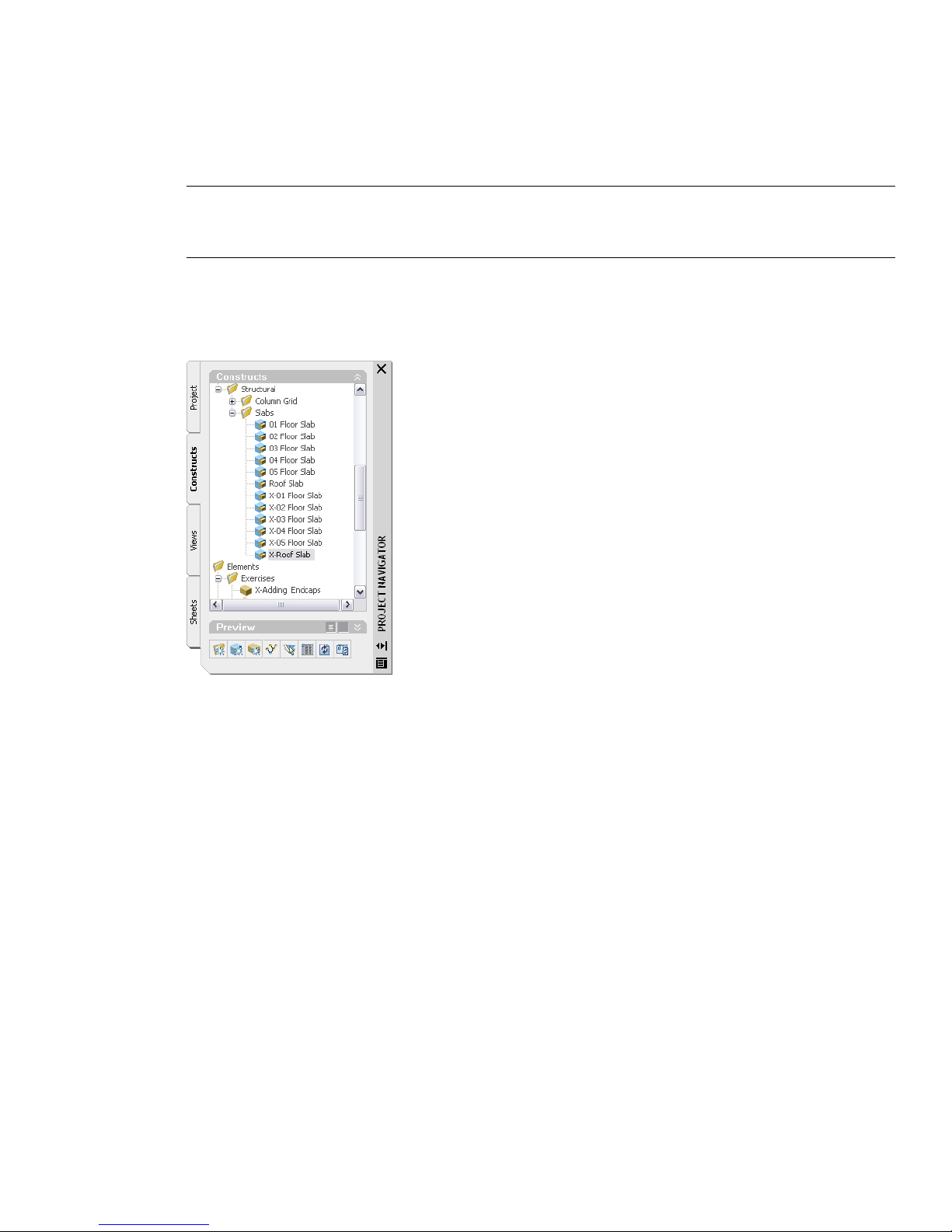
20 Modify the properties of the copies of the X-02 Floor Slab construct:
■ In the Project Navigator, right-click X-02 Floor Slab(3), and click Properties.
■ Enter X-03 Floor Slab for Name.
■ Enter Floor Slab 3rd Floor for Description.
■ Under Assignments, verify that level 2 is cleared, and that level 3 is selected.
IMPORTANT: Each copy of the 02 Floor Slab construct has a unique name with numbers in parentheses. These
numbers identify the level to which the construct is assigned. As you rename these constructs, verify that the name
you enter corresponds to the assigned level.
■ Click OK.
■ Repeat this process to rename X-02 Floor Slab(4) to X-04 Floor Slab and X-02 Floor Slab(R) to X-Roof Slab.
As you modify the properties for these constructs, enter appropriate descriptions, and verify their level
assignments.
The slabs you created are renamed.
21 Save all open project drawings.
In this exercise, you used the 01 Building Outline to generate a slab for the first floor of the building. You used the
same method with the Typical Building Outline to create the floor slab for level 2. Because the floor slab for level 2 is
the typical floor slab for the building, you copied X-02 Floor Slab to create slabs for the remaining levels and the roof.
You modified the properties of the copies of the X-02 Floor Slab construct to give the three new slabs appropriate
names, descriptions, and level assignments. Next, you modify the edge of the roof slab by applying a cant edge.
Exercise 2: Modifying the Edge of a Slab
Typically, slabs require a specific type of edge condition, such as a unique overhang, a curb, or a cant. You can apply
an edge condition to a slab edge by applying a slab edge style.
You can set the overhang length, orientation, and angle from the baseline, as well as adding a fascia and soffit to create
unique edge styles for your project. Fascia and soffits are defined by profiles that provide the two-dimensional (2D)
geometry of the component whose shape is then extruded along the slab edge. This exercise shows how to apply a cant
edge condition to the roof slab.
88 | Chapter 3 Developing Your Building Model Design
Page 95
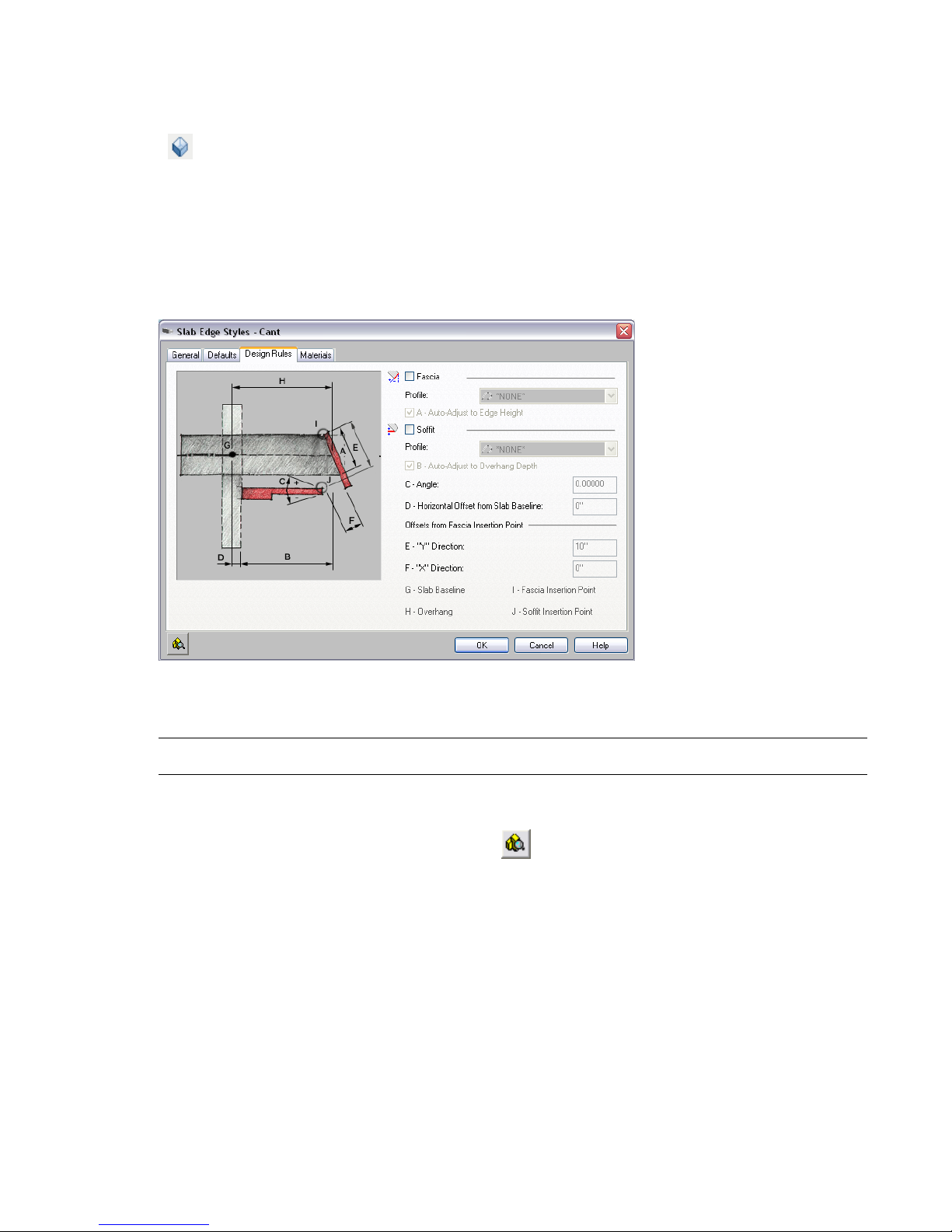
Create an edge condition
1 With the Project Navigator open, click the Constructs tab.
2 Open the X-Modifying a Slab Edge drawing.
3 Click on the View flyout on the Navigation toolbar.
4 On the Format Menu, click Style Manager.
5 In the left pane of the Style Manager, under X-Modifying a Slab Edge.dwg, expand Architectural Objects.
6 Right-click Slab Edge Styles, and click New.
7 Enter Cant for the name of the new slab edge style, and press ENTER.
8 Double-click the style, and assign an edge condition:
■ In the Slab Edge Styles dialog box, click the Design Rules tab.
■ Select Fascia.
■ Under Fascia, select Aec Slab - Cant for Profile to define the geometry of the fascia.
■ NOTE: This profile has been created for use in this exercise.
9 Preview the edge style:
■ In the bottom left corner of the Style Manager, click .
■ Select SE Isometric for the view direction.
Lesson 2: Laying out the Building Core | 89
Page 96

10 Click OK to close the Style Manager.
Modify the edges
11 In the drawing area, select the roof slab, right-click, and click Properties.
You can also double-click the roof slab to open the Properties palette.
12 On the Properties palette, under Dimensions, click Edges.
13 On the Slab Edges worksheet, select all edges:
■ Verify that Edge 1 is selected, and scroll to the bottom of the list.
■ Press and hold SHIFT, and select the last edge in the list.
14 Click the edge style for one of the roof edges (currently “None”), select Cant, and press ENTER.
All selected edges are assigned the Cant edge style.
15 Click OK.
16 Zoom in to a corner area to view the edge condition.
17 Save all open project drawings.
In this exercise, you created a slab edge style from an existing profile and applied a cant edge to all edges of the roof
slab. Next, you use wall tools to add interior partitions to your building model.
Exercise 3:Adding Interior Partitions
The building elements you need to complete your project are organized by tool palettes. The Design tool palette is
included in the Tool Palettes set. This palette includes a standard (generic) style of different building objects, such as
walls. When you add a wall, you can control properties of the wall, such as height, width, and baseline location, with
the Properties palette. When you add a wall, properties of the wall, such as height and width, are predefined by the
wall style assigned to the wall tool.
90 | Chapter 3 Developing Your Building Model Design
Page 97

This exercise shows how to use the wall tools provided on the Tutorial tool palette to add interior partitions to your
building model. Wall tools can be created based on customized wall styles. After you add walls to a drawing using tools,
you can modify them using the Properties palette or applying new styles.
With the exception of the first floor, each floor of the project has an identical building core that contains a centralized
bank of elevators, conference rooms, bathrooms, storage rooms, and two emergency exit stairwells. This building core
is contained in the Typical Core element.
In this exercise, the 01 Floor Partitions construct and the other finished partition plans have been created already. You
recreate the floor partition constructs for the second, third, and fourth floors. You create the floor partitions beginning
withX-02 Floor Partitions construct and reference in an element that contains the typical core of each floor of the
building. Any edits to the typical core element drawing will show in the floor partition constructs to which it is
referenced.
Create the floor partitions constructs
1 With the Project Navigator open, click the Constructs tab.
2 Under Constructs\Architectural, right-click Partitions, and click New ➤ Construct.
You can also click at the bottom of the Constructs tab.
3 On the Add Construct worksheet, specify the properties of the construct:
■ Enter X-02 Floor Partitions for Name.
■ Enter Interior Partitions 2nd Floorfor Description.
When you click to enter Description, a separate editing window opens. Enter the descriptive text, and click
OK.
■ Verify that Category is Constructs\Architectural\Partitions.
If a different category is shown, the Partitions category was not selected when you clicked Add Construct. To
change the category, click the current category, and select Partitions from the list that displays.
■ Under Assignments, select Level 2.
■ Click OK.
4 Repeat steps 2 and 3 three times to create floor partition constructs named X-03 Floor Partitions, X-04 Floor Partitions
and X-05 Floor Partitions. Enter appropriate descriptions for the constructs, and assign them to level 3, 4, and 5
respectively.
Lesson 2: Laying out the Building Core | 91
Page 98

Externally reference the typical core element to the X-02 Floor Partitions construct
5 In the Project Navigator, double-click X-02 Floor Partitions to open the file.
6 Under Elements, select X-Adding Interior Partitions, and drag the element icon into the drawing area.
The element is referenced into the X-02 Floor Partitions construct and is displayed in the drawing area.
7 Click on the Zoom flyout on the Navigation toolbar.
8 Save the drawing and keep it open.
Add interior partitions
9 On the Constructs tab, under Elements, double-click X-Adding Interior Partitions.
10 Click on the Zoom flyout on the Navigation toolbar, and zoom in to the large open room on the right.
11 Click on the Osnap button to turn off running object snaps.
12 Select the vertical left wall, right-click, and click Offset ➤ Copy.
13 Offset walls from the left wall to create interior partitions for the closets and bathrooms:
■ Press CTRL and select the center of the wall.
■ Move the cursor to the right, enter 5’8, and press ENTER.
■ Move the cursor to the right, enter 1'4, and press ENTER.
■ Move the cursor to the right, enter 2', and press ENTER.
■ Move the cursor to the right, enter 2', and press ENTER.
■ Move the cursor to the right, enter 2', and press ENTER.
■ Move the cursor to the right, enter 7', and press ENTER twice.
92 | Chapter 3 Developing Your Building Model Design
Page 99

14 Use an existing wall and the Object Snap toolbar to add walls to create additional interior partitions for the closets
and bathrooms:
■ Right-click one of the newly created walls, and select Select Similar.
■ In the Properties palette, under Dimensions, select Center for Justification.
■ Add two horizontal walls, as shown in the following illustration.
TIP: To add each horizontal wall, click on the Object Snap toolbar, and select the top left interior corner of the
room. Place the beginning of the wall directly down from the corner at 4’3”. Click on the Object Snap toolbar,
and select the right wall. Repeat to create a second wall 10’down from the corner.
By default, walls clean up automatically whenever they intersect other walls; however, this interaction depends
upon the position of the graph lines of the intersecting walls. The graph line of a wall runs along the length
of the wall. Typically, the graph line coincides with the justification line of the wall. When the graph lines of
two walls touch, the walls clean up automatically. When the graph lines do not touch, some manual adjustment
is necessary. You can view the walls with a Diagnostic display configuration to more clearly see the graph lines
and the direction of all objects including walls. Selecting a wall also shows the grips on the graph line. Use
the Lengthen wall grip to stretch a wall to the graph line of an intersecting wall to create a clean intersection.
The Lengthen grip displays on the graph line of a wall when the wall is selected and the lengthen grip maintains
the orientation of a wall.
15 Right-click, and click Basic Modify Tools ➤ Trim.
16 Trim the interior partitions to create the closet and bathroom spaces, as shown in the following illustration.
Lesson 2: Laying out the Building Core | 93
Page 100

Use grips to adjust wall lengths
17 Select the lower horizontal wall you added to display its grips, and hover the cursor over the wall grips to locate
the Lengthen grips.
Lengthen grips exist at both ends of the wall segment and can be used to shorten the length of the wall.
TIP: The AutoCAD commands such as Break, Trim, Extend, and Fillet work with walls. The graph line represents the
precise points of wall placement and for extend/trim the cutting edge can be a line or polyline as well as another wall.
18 Select the Lengthen grips, and stretch the ends of the wall. Enter 5’ to shorten the wall, as shown in the illustration
below.
19 Right-click, and click Deselect All to turn off the wall grips.
Change the style of a wall
20 Zoom in to the emergency exit stairwell area on the right of the core.
94 | Chapter 3 Developing Your Building Model Design
 Loading...