

Page 1

Getting Started
January 2008
Page 2

© 2008 Autodesk, Inc. All rights reserved. Except as otherwise permitted by Autodesk, Inc., this publication, or parts thereof, may
not be reproduced in any form, by any method, for any purpose.
Certain materials included in this publication are reprinted with the permission of the copyright holder.
Trademarks
The following are registered trademarks or trademarks of Autodesk, Inc., in the USA and other countries: 3DEC (design/logo),
3December, 3December.com, 3ds Max, ActiveShapes, Actrix, ADI, Alias, Alias (swirl design/logo), AliasStudio, Alias|Wavefront
(design/logo), ATC, AUGI, AutoCAD, AutoCAD Learning Assistance, AutoCAD LT, AutoCAD Simulator, AutoCAD SQL Extension,
AutoCAD SQL Interface, Autodesk, Autodesk Envision, Autodesk Insight, Autodesk Intent, Autodesk Inventor, Autodesk Map, Autodesk
MapGuide, Autodesk Streamline, AutoLISP, AutoSnap, AutoSketch, AutoTrack, Backdraft, Built with ObjectARX (logo), Burn, Buzzsaw,
CAiCE, Can You Imagine, Character Studio, Cinestream, Civil 3D, Cleaner, Cleaner Central, ClearScale, Colour Warper, Combustion,
Communication Specification, Constructware, Content Explorer, Create>what's>Next> (design/logo), Dancing Baby (image),
DesignCenter, Design Doctor, Designer's Toolkit, DesignKids, DesignProf, DesignServer, DesignStudio, Design|Studio (design/logo),
Design Your World, Design Your World (design/logo), DWF, DWG, DWG (logo), DWG TrueConvert, DWG TrueView, DXF, EditDV,
Education by Design, Extending the Design Team, FBX, Filmbox, FMDesktop, Freewheel, GDX Driver, Gmax, Heads-up Design, Heidi,
HOOPS, HumanIK, i-drop, iMOUT, Incinerator, IntroDV, Inventor, Inventor LT, Kaydara, Kaydara (design/logo), LocationLogic, Lustre,
Maya, Mechanical Desktop, MotionBuilder, ObjectARX, ObjectDBX, Open Reality, PolarSnap, PortfolioWall, Powered with Autodesk
Technology, Productstream, ProjectPoint, Reactor, RealDWG, Real-time Roto, Render Queue, Revit, Showcase, SketchBook,
StudioTools, Topobase, Toxik, Visual, Visual Bridge, Visual Construction, Visual Drainage, Visual Hydro, Visual Landscape, Visual Roads,
Visual Survey, Visual Syllabus, Visual Toolbox, Visual Tugboat, Visual LISP, Voice Reality, Volo, and Wiretap.
The following are registered trademarks or trademarks of Autodesk Canada Co. in the USA and/or Canada and other countries:
Backburner, Discreet, Fire, Flame, Flint, Frost, Inferno, Multi-Master Editing, River, Smoke, Sparks, Stone, Wire.
All other brand names, product names or trademarks belong to their respective holders.
Disclaimer
THIS PUBLICATION AND THE INFORMATION CONTAINED HEREIN IS MADE AVAILABLE BY AUTODESK, INC. "AS IS." AUTODESK, INC.,
DISCLAIMS ALL WARRANTIES, EITHER EXPRESS OR IMPLIED, INCLUDING BUT NOT LIMITED TO ANY IMPLIED WARRANTIES OF
MERCHANTABILITY OR FITNESS FOR A PARTICULAR PURPOSE REGARDING THESE MATERIALS.
Published by:
Autodesk, Inc.
111 Mclnnis Parkway
San Rafael, CA 94903, USA
Page 3

Contents
Make the Transition from Paper to CAD . . . . . . . . .1
Draw to Scale . . . . . . . . . . . . . . . . . . . . 3
Lay Out Your Drawing . . . . . . . . . . . . . . . . . 5
Organize Drawing Information . . . . . . . . . . . . . . 7
Establish Drafting Standards . . . . . . . . . . . . . . . 9
Draw Efficiently . . . . . . . . . . . . . . . . . . 11
Draw Accurately . . . . . . . . . . . . . . . . . . 13
View Your Drawing . . . . . . . . . . . . . . . . . 15
Create Dimensions and Text . . . . . . . . . . . . . . 17
Modify Your Drawing . . . . . . . . . . . . . . . . 19
Chapter 1 Introduction . . . . . . . . . . . . . . . . . 21
Why You Should Use this Guide . . . . . . . . . . . . . 22
Tutorials and Command Access . . . . . . . . . . . . . 22
Get Additional Information . . . . . . . . . . . . . . 23
Chapter 2 Work with Commands . . . . . . . . . . . . . . 29
Use the Mouse . . . . . . . . . . . . . . . . . . 30
Cancel a Command . . . . . . . . . . . . . . . . . 30
Start a Command . . . . . . . . . . . . . . . . . 30
Undo or Redo Commands . . . . . . . . . . . . . . . 34
Chapter 3 Change Views . . . . . . . . . . . . . . . . . 37
Zoom to Magnify a View . . . . . . . . . . . . . . . 38
Pan to Reposition a View . . . . . . . . . . . . . . . 39
Chapter 4 Drawing Setup . . . . . . . . . . . . . . . . . 43
Start a Drawing . . . . . . . . . . . . . . . . . . 44
Plan the Drawing Units and Scale . . . . . . . . . . . . 46
Understand Models and Layouts . . . . . . . . . . . . . 48
Organize Drawings with Layers . . . . . . . . . . . . . 50
Tutorial: Tour a Drawing . . . . . . . . . . . . . . . 52
Page 4

Chapter 5 Draw Objects . . . . . . . . . . . . . . . . . 55
Object Properties Overview . . . . . . . . . . . . . . . 56
Draw Lines . . . . . . . . . . . . . . . . . . . . 64
Draw Circles and Arcs . . . . . . . . . . . . . . . . 67
Chapter 6 Precision Drawing . . . . . . . . . . . . . . . . 71
Set Grid and Snap Values . . . . . . . . . . . . . . . 72
Draw with Coordinates . . . . . . . . . . . . . . . . 74
Snap to Precise Points on Objects . . . . . . . . . . . . . 76
Object Snap Descriptions . . . . . . . . . . . . . . . 78
Specify Angles and Distances . . . . . . . . . . . . . . 79
Chapter 7 Make Modifications . . . . . . . . . . . . . . . . 85
Select Objects to Edit . . . . . . . . . . . . . . . . . 86
Erase, Extend, and Trim Objects . . . . . . . . . . . . . 87
Duplicate Objects . . . . . . . . . . . . . . . . . . 90
Move and Rotate Objects . . . . . . . . . . . . . . . 93
Fillet Corners . . . . . . . . . . . . . . . . . . . 94
Use Editing Aids . . . . . . . . . . . . . . . . . .109
Analyze Drawings . . . . . . . . . . . . . . . . . .111
Chapter 8 Add Symbols and Hatches . . . . . . . . . . . . 115
Overview of Blocks . . . . . . . . . . . . . . . . .116
Insert Blocks . . . . . . . . . . . . . . . . . . .117
Overview of Hatches . . . . . . . . . . . . . . . . .119
Insert Hatches or Solid Fills . . . . . . . . . . . . . . .120
Chapter 9 Add Text to a Drawing . . . . . . . . . . . . . 125
Create and Modify Text . . . . . . . . . . . . . . . .126
Work with Text Styles . . . . . . . . . . . . . . . .128
Set Text Size for the Viewport Scaling. . . . . . . . . . . .129
Chapter 10 Add Dimensions. . . . . . . . . . . . . . . . 133
Dimensions Overview . . . . . . . . . . . . . . . .134
Create Dimensions . . . . . . . . . . . . . . . . .135
Use Dimensioning Options . . . . . . . . . . . . . . .138
Create and Modify Dimension Styles . . . . . . . . . . . .140
Modify Dimensions . . . . . . . . . . . . . . . . .142
iv | Contents
Page 5

Chapter 11 Create Layouts and Plots . . . . . . . . . . . . . 147
Work with Layouts . . . . . . . . . . . . . . . . . 148
Choose and Configure Plotters . . . . . . . . . . . . . 151
Plot from a Layout . . . . . . . . . . . . . . . . . 153
Glossary . . . . . . . . . . . . . . . . . . . 159
Index . . . . . . . . . . . . . . . . . . . . 169
Contents | v
Page 6

vi
Page 7
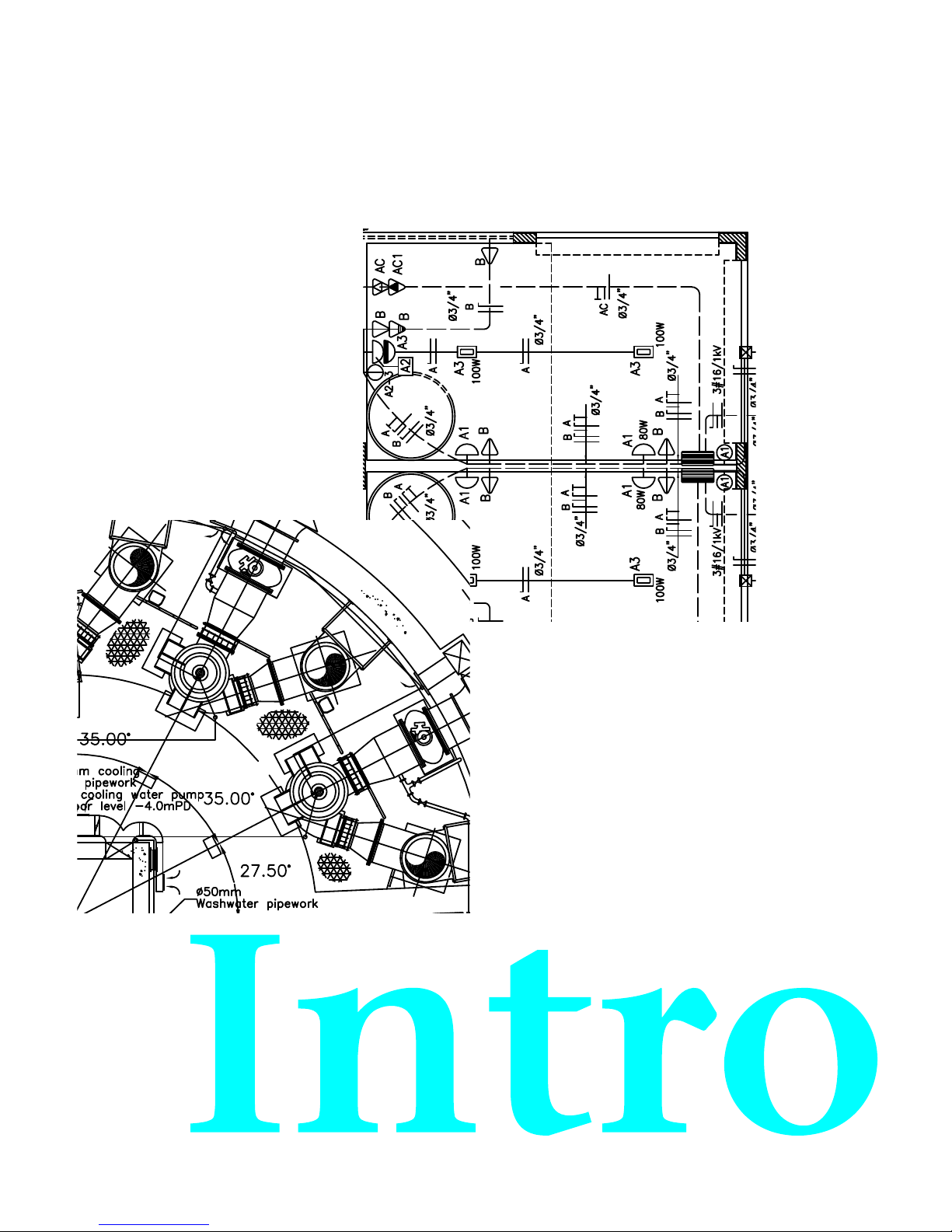
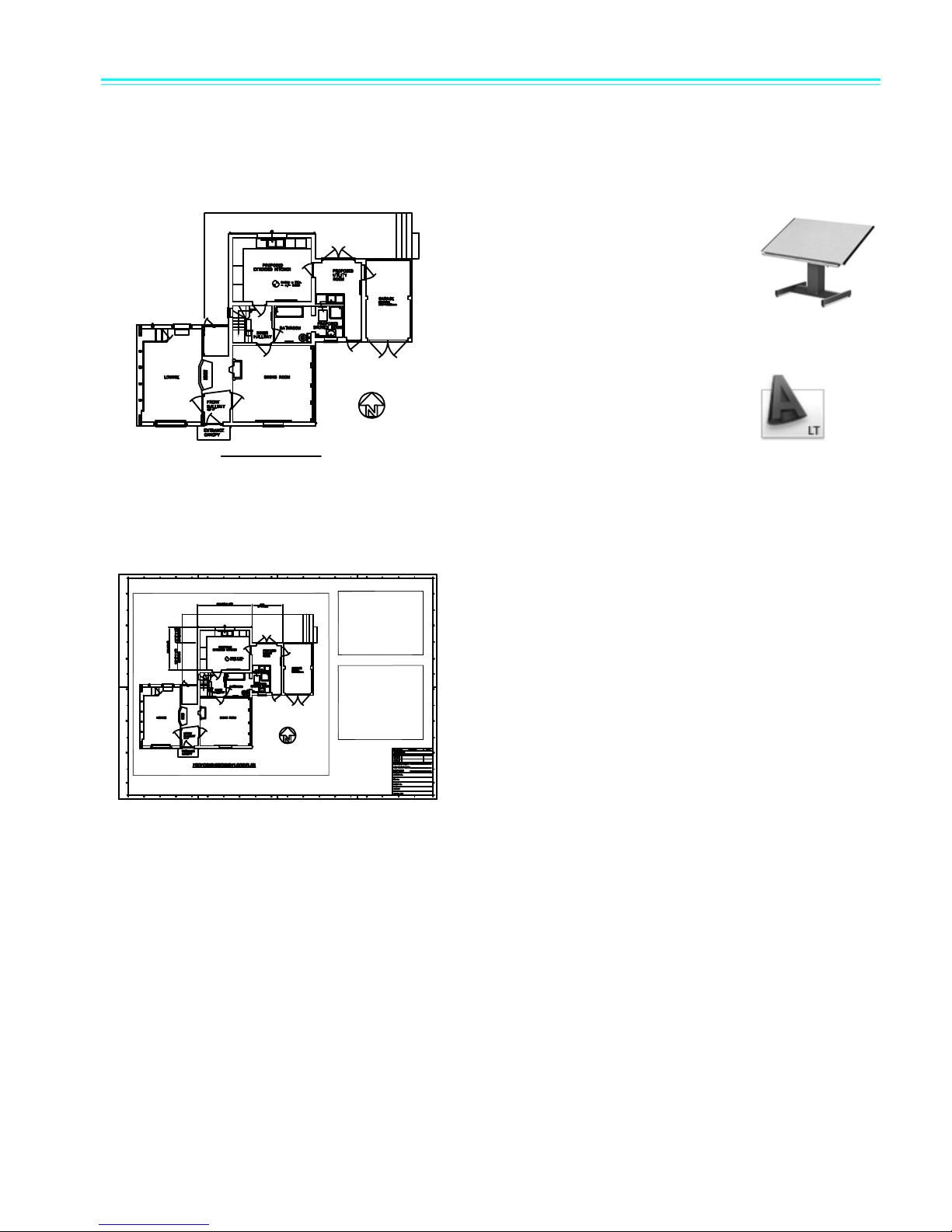
Make the Transition from Paper to
CAD
Page 8
$
$
127(
6(('(7$,/%
127(
6+$)7'(7$,/
127(
5
;
3$*)
6$(
127(
;
5
;
;
5;
5
5()
5
5
5
5
5
;
6/276
Page 9
Draw to Scale
5
5()
5
5
5
5
5
;
3$*)
6$(
;
5
;
5;
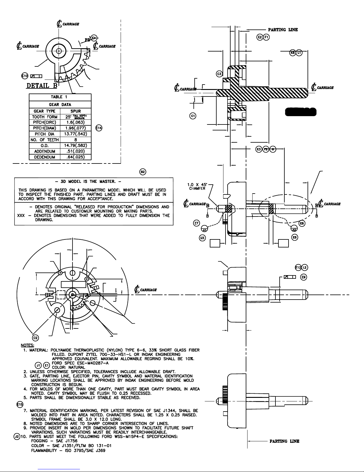
Draw the object at 1:1 scale in the units you
choose.
When you lay out and plot your drawing, you
can specify any scale.
Drawing scale is something you consider when laying out your drawing. You establish scale
differently in CAD than you do with manual drafting.
With manual drafting, you
must determine the scale of a
view before you start
drawing. This scale compares
the size of the actual object to
the size of the model drawn
on paper.
With AutoCAD and
AutoCAD LT, you first decide
what units of measurement
you will use, and then draw
your model at 1:1 scale.
For example, when you draw a motor part, the
length of one unit might equal one millimeter
or one inch. When you draw a map, one unit
might equal one kilometer or one mile.
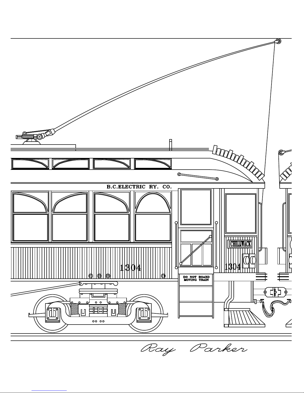
This drawing of a mechanical carriage uses
millimeters for the length of one unit. Views of
the part were scaled later to create the layout
for the printed drawing.
Draw to Scale | 3
Page 10
352326('*5281')/2253/$1
&
$
352326('(/(9$7,21$$>6287+@
&
%
; ;
<
<
==
Page 11
Lay Out Your Drawing
You create your basic design, or
model, in a drawing area called model
space.
When you’re ready to print, you can arrange
different views of your model in a layout.
On paper, a layout is constrained by the sheet size you use. In CAD, you are not limited to one
particular layout or sheet size.
When you draft manually, you
first select a sheet, which usually
includes a preprinted border and
title block. Then you determine
the location for views—plans,
elevations, sections, and details.
Finally, you start to draw.
With AutoCAD and AutoCAD LT,
you first draw your design, or
model, in a working environment
called model space. You can then
create a layout for that model in an environment
called paper space.
A layout represents a drawing sheet. It typically
contains a border, title block, dimensions, general
notes, and one or more views of the model
displayed in layout viewports. Layout viewports are
areas, similar to picture frames or windows,
through which you can see your model. You scale
the views in viewports by zooming in or out.
In this drawing of a cottage, layout viewports
display the model in plan and elevation views.
Lay Out Your Drawing | 5
Page 12
Page 13
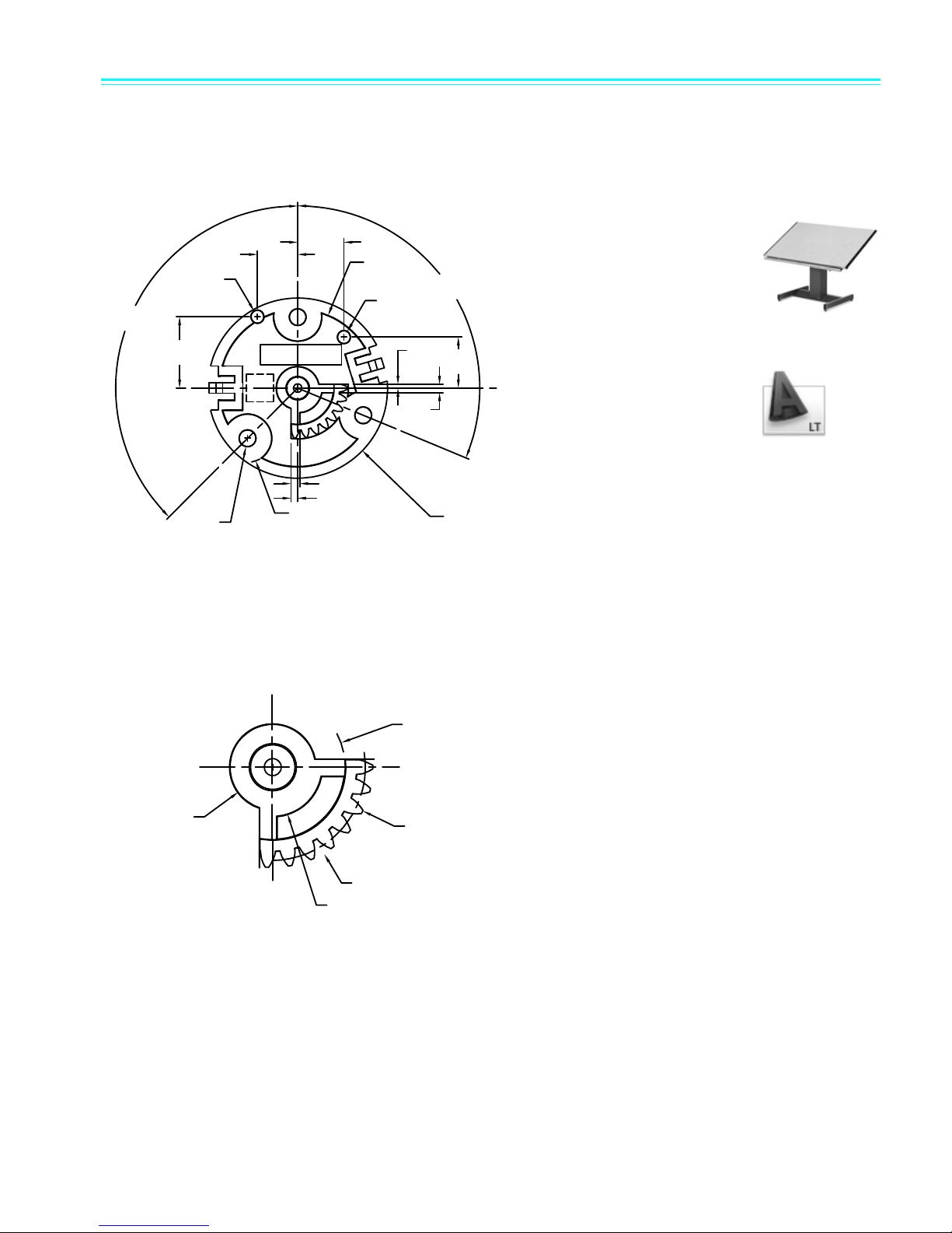
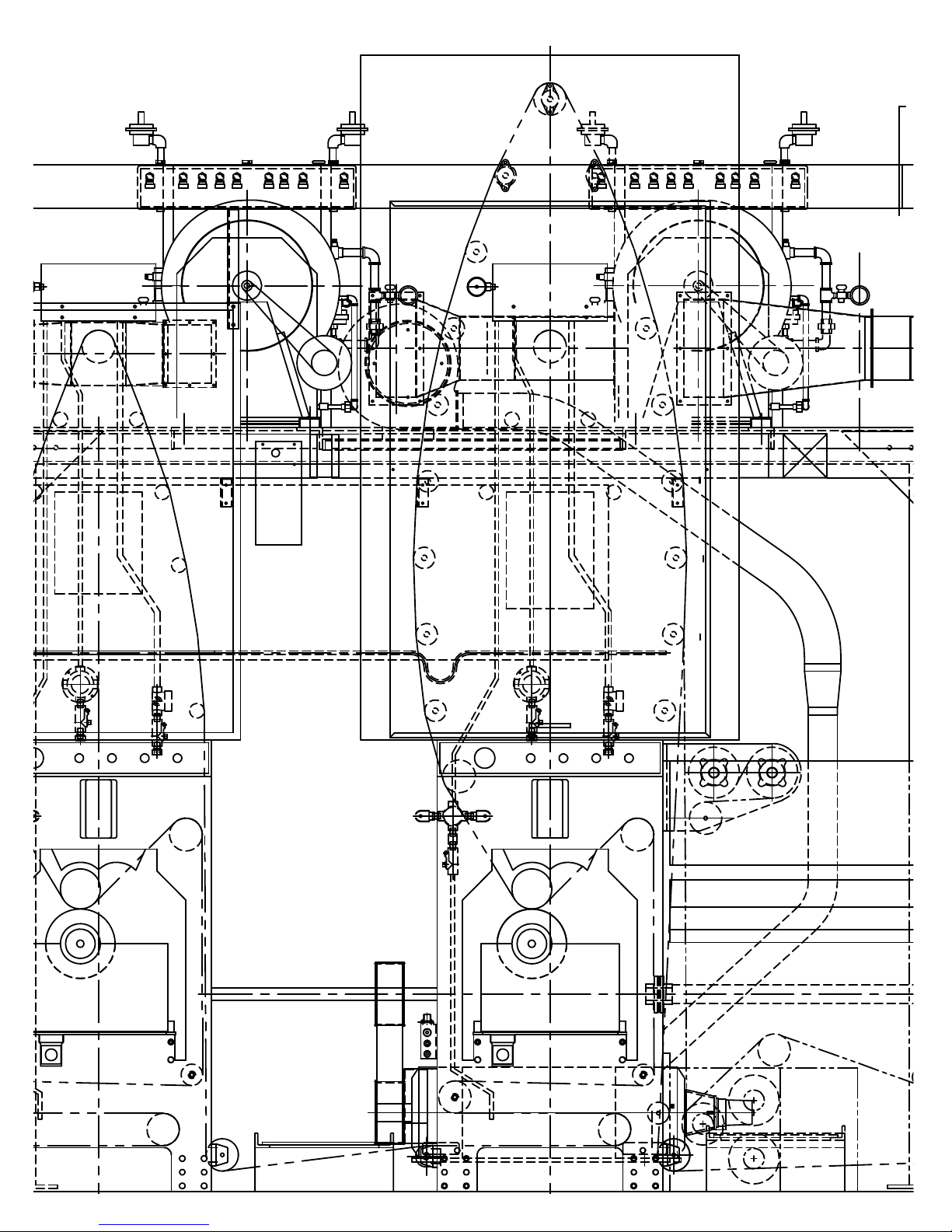
Organize Drawing Information
Turn off layers to hide complex
details as you work.
Display layers when you need
to see all components.
In both manual drafting and CAD, you need a way to organize your drawing content—a method for
separating, sorting, and editing specific drawing data.
With manual drafting, you can separate
information onto individual transparent
overlays. For example, a building plan might
contain separate overlays for its structural,
electrical, and plumbing components.
With AutoCAD and AutoCAD LT, layers are
equivalent to transparent overlays. As with
overlays, you can display, edit, and print layers
separately or in combination.
You can name layers to help track content, and lock layers so
they can't be altered. Assigning settings such as color, linetype, or
lineweight to layers helps you comply with industry standards.
You can also use layers to organize drawing objects for plotting.
Assigning a plot style to a layer makes all the objects drawn on
that layer plot in a similar manner.
This drawing of a press uses layers to define different linetypes
and colors.
Organize Drawing Information | 7
Page 14

Page 15
Establish Drafting Standards
Dimension, text, and linetype
styles can be established in a
template drawing and used for
creating new drawings.
Whether you work as a member of a team or on an individual project, developing standards is a
requirement for efficient communication.
Manual drafting requires meticulous
accuracy in drawing linetypes,
lineweights, text, dimensions, and
more. Standards must be established
in the beginning and applied
consistently.
With AutoCAD and AutoCAD LT, you
can ensure conformity to industry or
company standards by creating styles
that you can apply consistently.
You can create styles for text, dimensions, and
linetypes. A text style, for example, establishes font and
format characteristics such as height, width, and slant.
You can save styles, layers, layouts, title block and
border information, and some command settings in
drawing template files. Using drawing templates helps
you quickly start new drawings that conform to
standards.
This drawing of a roadway plan uses styles to maintain
drafting standards for text, dimensioning, and
linetypes.
Establish Drafting Standards | 9
Page 16
Page 17
Draw Efficiently
You can save drafting time by drawing one
half of an item and then mirroring it to create
the other half.
Draw with less effort and revise with more speed: these are two primary reasons you use CAD. You
are provided with a complete set of drawing and editing tools to help eliminate repetitive, timeconsuming drafting tasks.
With manual drafting, you use drawing
tools that include pencils, scales,
compasses, parallel rules, templates, and
erasers. Repetitive drawing and editing
tasks must be done manually.
In AutoCAD and AutoCAD LT, you can
choose from a variety of drawing tools
that create lines, circles, spline curves,
and more.
You can easily move, copy, offset, rotate, and mirror
objects. You can also copy objects between open
drawings.
In this drawing of a trolley, copying and mirroring were
used to create repeated and symmetrical features.
Offsetting was also used to draw parallel lines more
efficiently.
Draw Efficiently | 11
Page 18
Page 19
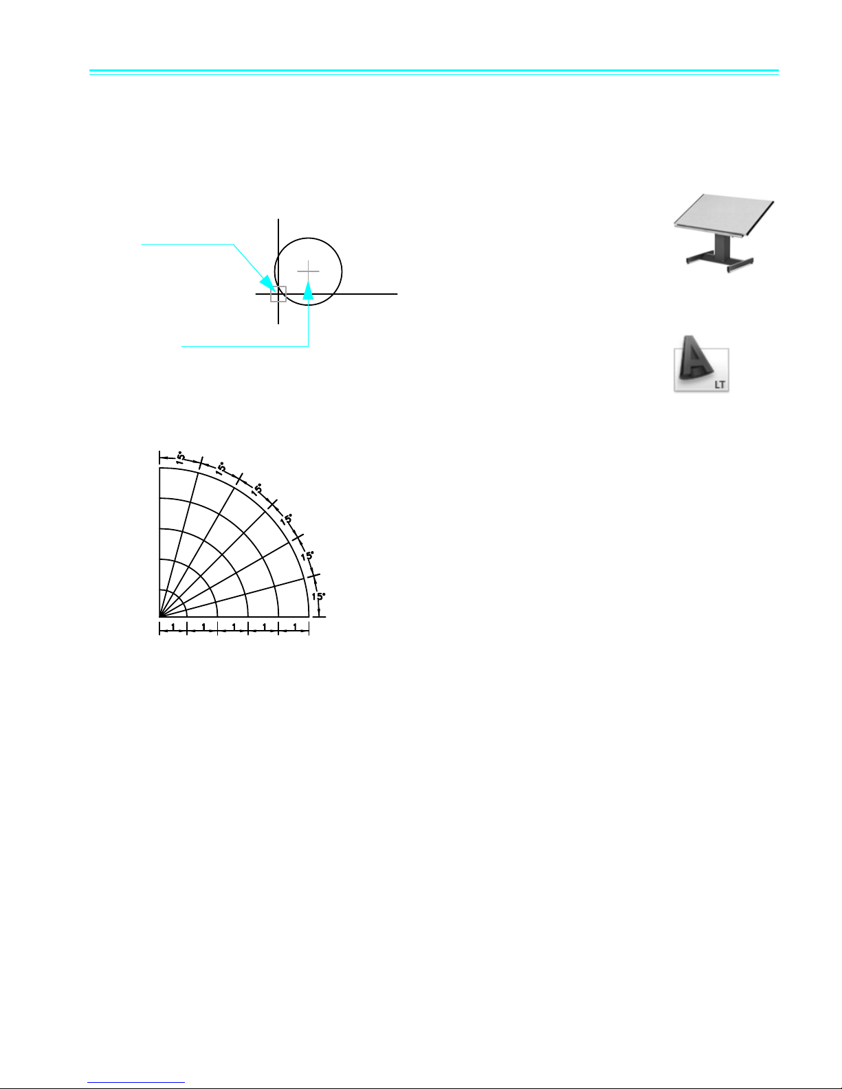
Draw Accurately
The polar tracking feature
displays visual guidelines at
specific angles and can snap
the cursor to an angle.
With object
snaps, when you
place your cursor
here…
you can snap to the
center point
automatically.
Engineering and architectural drawings require a high degree of accuracy. With CAD, you draft more
accurately than with manual methods.
With manual drafting, you must
draw objects carefully to ensure
correct size and alignment. Objects
drawn to scale must be manually
verified and dimensioned.
With AutoCAD and AutoCAD LT,
you can use several methods to
obtain exact dimensions.
The simplest method is to locate
points by snapping to an interval on
a rectangular grid.
Another method is to specify exact coordinates.
Coordinates specify a drawing location by indicating
a point along an X and Y axis or a distance and angle
from another point.
With object snaps, you can snap to locations on
existing objects, such as an endpoint of an arc, the
midpoint of a line, or the center point of a circle.
With polar tracking, you can snap to previously set
angles and specify distances along those angles.
In this drawing of a pumping station, object snaps were
used to ensure that lines connected perfectly. Polar
tracking was used to draw lines at correct angles.
Draw Accurately | 13
Page 20
Page 21
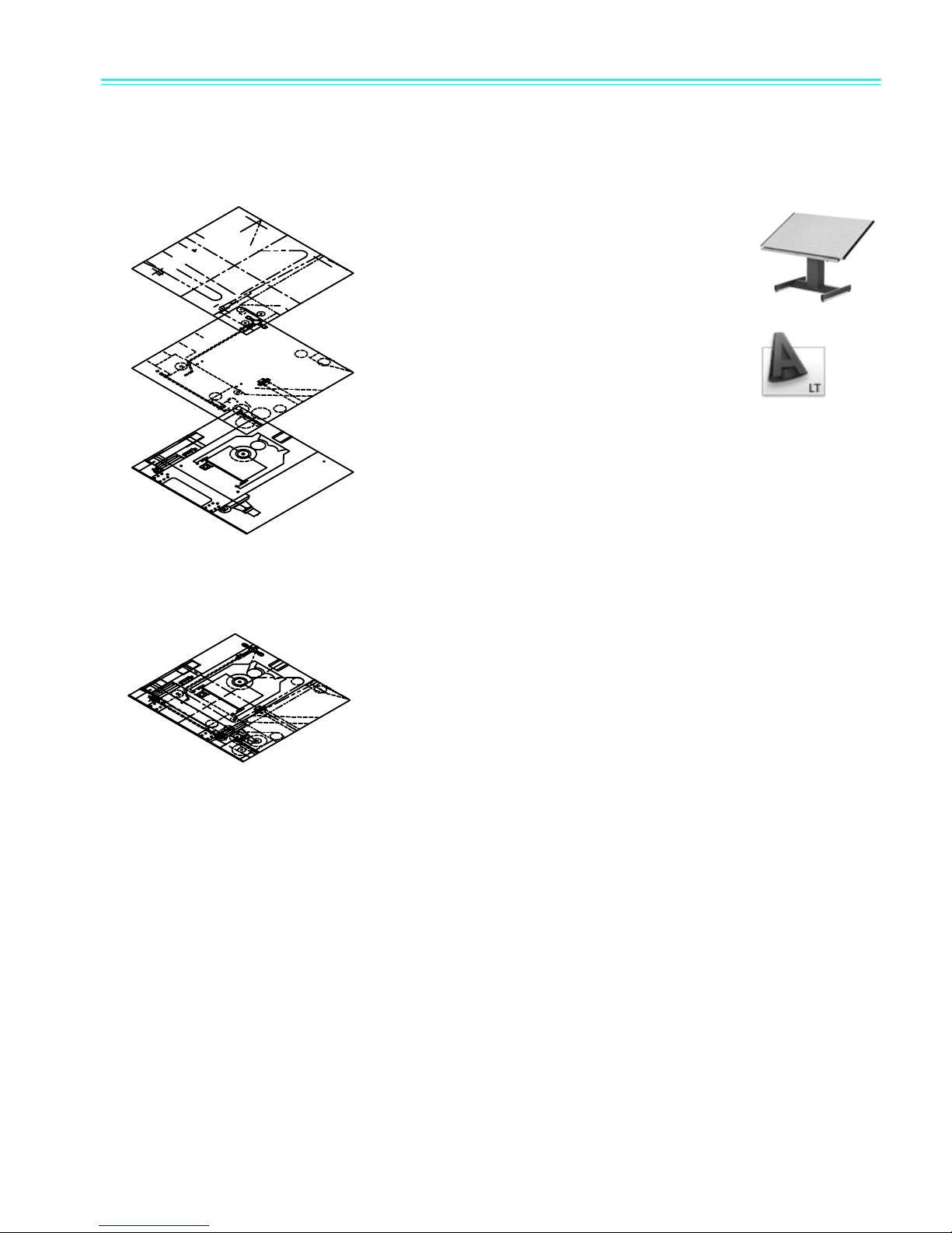
View Your Drawing
You can zoom out to see more of your
design, or zoom in to see more detail.
You can pan to shift to another area of your
design.
The power of CAD makes it easy for you to quickly view different parts of your design at different
magnifications.
With manual drafting, the size
and resolution of your drawing
is fixed.
With AutoCAD and AutoCAD
LT, the size and resolution of
your drawing can be changed as
needed.
To do detailed work, you can
increase display size by zooming
in. You can zoom out to display
more of the drawing. To move to another section
of a drawing, you pan the drawing without
changing magnification.
You can zoom and pan to create the best working
conditions. This can be invaluable when working
on large and detailed drawings, such as this
health spa plan.
View Your Drawing | 15
Page 22
/
Page 23
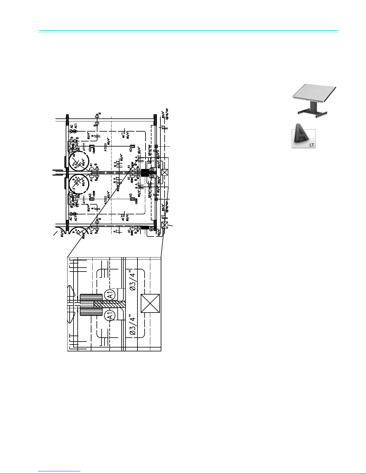
Create Dimensions and Text
If you make dimensions associative, you can update the
dimension size and value automatically when you
stretch or scale the dimensioned object.
You can create leader lines with associated text. If you
move the text, the leader is adjusted automatically.
Creating accurate dimensions and consistent, legible text is a time-consuming task for the manual
drafter. CAD provides ways to streamline this task.
With manual drafting, if you
resize any part of the drawing,
you must erase and then
redraw the dimensions.
Changing text can often
involve relettering the whole
drawing.
With AutoCAD and AutoCAD
LT, you create associative
dimensions and text on the
layout in paper space.
Associative dimensions are
tied to the underlying model.
Changes to the model automatically update the
dimension values.
Standard types of dimensions include linear,
radial, ordinate, angular, baseline, and more.
You can easily revise the content, font, size,
spacing, and rotation of text in dimensions and
notes.
In this detail drawing of a gutter, the text,
leaders, and dimensions describe the required
hardware.
Create Dimensions and Text | 17
Page 24
Page 25
Modify Your Drawing
Once you draw something, you can easily copy it without
having to re-create it.
Revisions are a part of any drawing project. Whether you work on paper or with CAD, you will need
to modify your drawing in some way.
On paper, you must erase and redraw to make revisions to your drawing manually.
CAD eliminates tedious manual editing by providing a variety of editing tools. If
you need to copy all or part of an object, you don’t have to redraw it. If you need
to remove an object, you can erase it with a few clicks of the mouse. And if you
make an error, you can quickly undo your actions.
Once you draw an object, you never need to redraw it. You can modify existing
objects by mirroring, rotating, scaling, stretching, trimming, and more. You can
also change object properties, such as linetype, lineweight, color, and layer, at any
time.
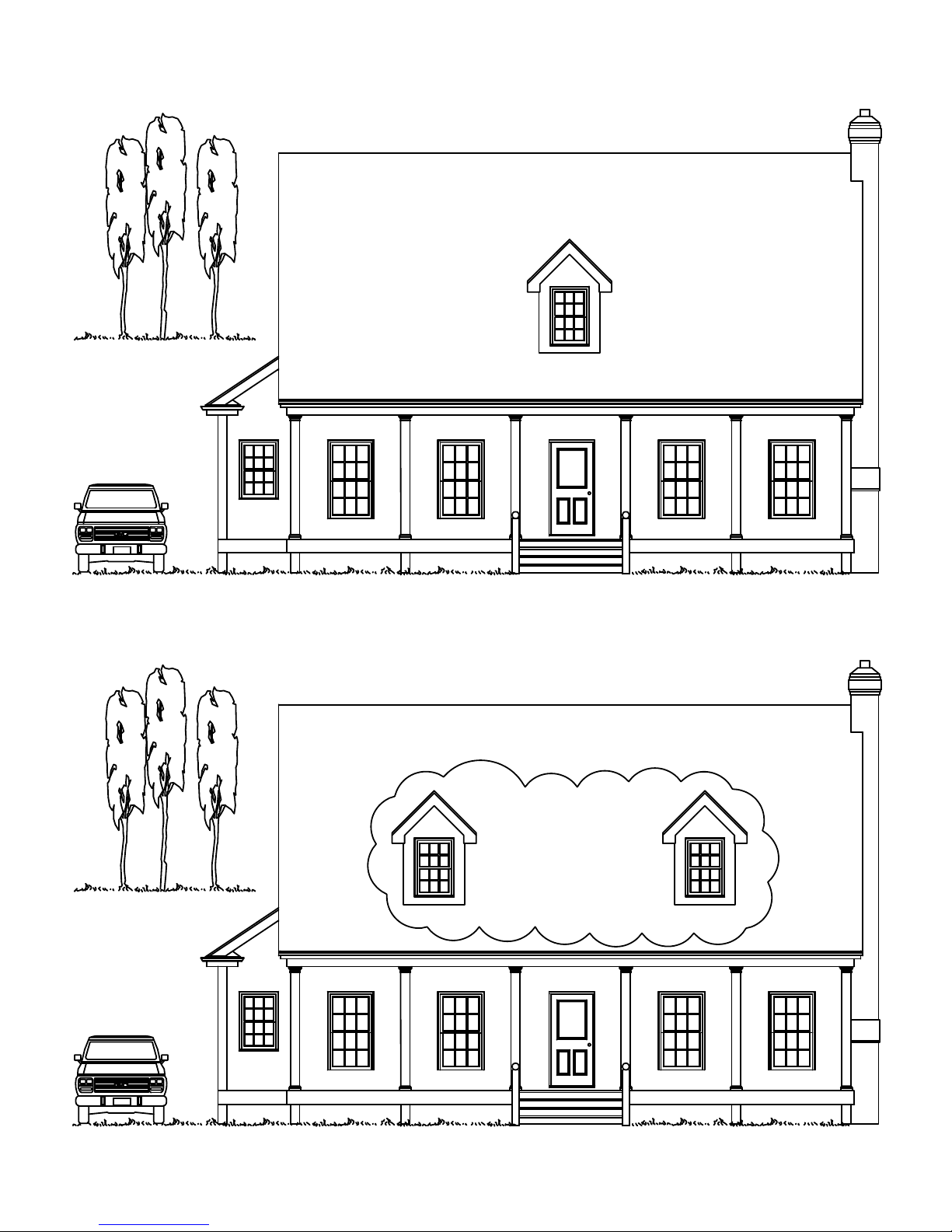
These before-and-after drawings show some typical edits to a house elevation. The revision cloud
feature is used to mark areas of change.
Modify Your Drawing | 19
Page 26

20
Page 27

Introduction
Why You Should Use this Guide . . . . . . . . . . . . . . . . . . . . . . . . . . . . . . . . . . . . . 22
Tutorials and Command Access. . . . . . . . . . . . . . . . . . . . . . . . . . . . . . . . . . . . . . 22
Get Additional Information. . . . . . . . . . . . . . . . . . . . . . . . . . . . . . . . . . . . . . . . . .23
Page 28
Why You Should Use this Guide
Menu Browser
This Getting Started guide provides an introduction to the most commonly used features of both
AutoCAD and AutoCAD LT. Use it to learn the basic features so you can begin working quickly.
Because you are provided with a rich set of features, there are often many ways of accomplishing a
task. This guide focuses on the following:
■ What do you need to know to get started?
■ What is the recommended method for using the features presented?
After you become more familiar with the features, you will find your own ways of working efficiently
based on the type of work that you do.
Tutorials and Command Access
There are severals ways you can access commands in AutoCAD and AutoCAD LT. They can be
accessed through the command line, the ribbon, toolbars, palettes, and the Menu Browser.
Because the ribbon might have been customized, and some commands are not accessible from the
ribbon, the tutorials in this guide usually direct you to access commands through the Menu Browser.
22 | Chapter 1 Introduction
Page 29
NOTE All screen shots and dialog boxes in this guide display AutoCAD LT in the title bar. For the
2 Enter a
keyword
3 Double-click to
view a topic
4 Click to display a concept
related to the selected topic
5 Click to list
procedures related to
the selected topic
6 Click to list
commands related to
the selected topic
1 Click the
Index tab
explanations and tutorials in the Getting Started guide, there is no difference whether you use AutoCAD
or AutoCAD LT. The features presented are identical.
Get Additional Information
Additional resources are available when you need more information. From the Help menu, you can
access the following resources:
■ Help provides procedures, conceptual information, and command descriptions. You can also
press F1 at the Command prompt, in a dialog box, or at a prompt within a command to display
Help information.
■ New Features Workshop provides a series of overviews about new features.
■ Additional Resources provides several options for additional help from the Web.
Access Related Topics in the Help System
Keyword references are displayed at the end of most Getting Started topics. For example, the
following information indicates that you can find concepts, procedures, commands, and system
variables related to the LINE command by entering line in the Index tab of the Help window.
LINE
Try it: Locate a Help topic using a keyword
■ Start AutoCAD or AutoCAD LT and press the F1 key. Then follow the steps in the illustration.
Get Additional Information | 23
Page 30
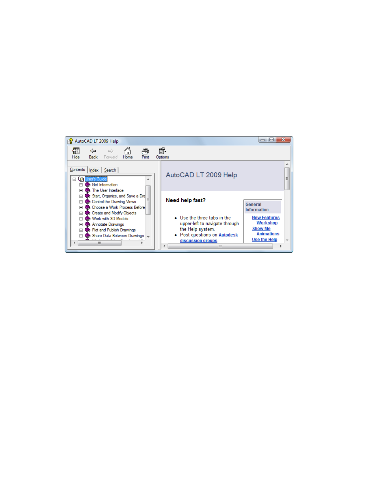
Tutorial: Use the Help System
In this tutorial, you will use the Help system to find information about how to start a drawing with
a template file and how to create a layout.
NOTE It is important to learn how to use the Help system effectively. The Help system can provide
answers to save you from needless frustration.
1 Start AutoCAD or AutoCAD LT and press F1 to display the Help window.
2 In the left pane of the Help window, click the Contents tab if necessary to display the table of
contents. Then click the plus sign (+) next to User’s Guide.
The User’s Guide expands to display a list of chapters.
3 In the left pane, click directly on the title, Start, Organize, and Save a Drawing. The right pane of
the Help window displays links to several topics, with descriptions for each one.
4 In the right pane, click Start a Drawing. Then click Use a Template File to Start a Drawing.
You have navigated to a destination topic in the Help system. Notice that the table of contents
in the left pane displays the topic structure for easy navigation.
24 | Chapter 1 Introduction
Page 31

5 Click the Procedure tab. Then click the first procedure on the list. Click the Procedure tab to
redisplay the list.
6 Click the Quick Reference tab. The Quick Reference tab lists all commands and system variables
that are associated with this topic.
If you click a link on this tab, the Command Reference is opened in Help, and provides details
about command and dialog box options.
7 Next, in the left pane, click the Search tab.
You will now locate topics that contain the word layout.
8 Type the word layout and press ENTER.
Several topics that contain the word layout are displayed. For the best results, enter several
keywords or an exact phrase in quotes.
NOTE You can click the column labeled Title to sort the list of topics alphabetically. Then, click
the column labeled Location to sort the list of topics by book: Command Reference, User’s Guide,
and so on.
9 Scroll down to find the User’s Guide topic, Work on a Layout Tab. Then double-click the topic.
The topic is displayed. But how do you know where you are in the table of contents? How can
you display an adjacent, related topic?
Get Additional Information | 25
Page 32

10 In the left pane, click the Contents tab.
The table of contents opens to the current topic. Use this method to find related topics easily.
NOTE If the table of contents does not automatically open to the current topic, click the Concept tab
in the right pane.
11 In the left pane, right-click any topic and then click Close All.
This is a quick method for collapsing the table of contents when too many subtopics are
displayed.
12 Close the Help window.
26 | Chapter 1 Introduction
Page 33

For more information, read Use the Help System Efficiently. In the Help system, on the Contents tab,
click User’s Guide ➤ Get Information ➤ Find the Information You Need ➤ Use the Help System
Efficiently.
To get started
Action Menu Browser
Access the Help system Help ➤ Help
Use New Features Workshop Help ➤ New Features Workshop
Find training resources Help ➤ Additional Resources ➤
Online Training Resources
Help system
HELP
Review and Recall
1 What is the purpose of the tabs in the right pane of the Help window?
2 In the left pane of the Help window, when would you use the Contents tab rather than the Index tab?
3 From what menu can you get information about new features?
Get Additional Information | 27
Page 34

28
Page 35

Work with Commands
Use the Mouse . . . . . . . . . . . . . . . . . . . . . . . . . . . . . . . . . . . . . . . . . . . . . . . . . . . 30
Cancel a Command. . . . . . . . . . . . . . . . . . . . . . . . . . . . . . . . . . . . . . . . . . . . . . . . 30
Start a Command . . . . . . . . . . . . . . . . . . . . . . . . . . . . . . . . . . . . . . . . . . . . . . . . .30
Undo or Redo Commands . . . . . . . . . . . . . . . . . . . . . . . . . . . . . . . . . . . . . . . . . .34
Page 36

Use the Mouse
specify points or select objects
display a shortcut menu
rotate to zoom, press to pan
Most people use a mouse as their pointing device. On a two-button mouse, the left button is usually
the pick button, used to specify points or select objects in the drawing area. With the right button,
you can display a shortcut menu that contains relevant commands and options. Different shortcut
menus are displayed depending on where you move the cursor.
NOTE To see what options are available in any situation, try right-clicking to display a shortcut menu.
A wheel mouse is a two-button mouse with a small wheel between the buttons. This wheel can be
rotated or pressed down to zoom and pan your drawing quickly. It is highly recommended that you
use a wheel mouse.
Cancel a Command
If you accidentally click in the screen, display a shortcut menu, or start a command, you can always
escape by pressing the ESC key on your keyboard.
Try it: Cancel a selection
■ Click in the drawing area and move the mouse. You are now in an object selection mode. Press
ESC to cancel.
Start a Command
You can start a command using the Menu Browser, a toolbar, a palette, or the command line. Because
AutoCAD and AutoCAD LT are very flexible, you can work in the way that feels most comfortable
to you.
You can choose commands from several different kinds of menus:
30 | Chapter 2 Work with Commands
Page 37

■ Menu Browser access is from the bright red button at the top-left corner of the application
command window
command line
window. All the commands for the tutorials in this book are accessible from these menus.
■ The Object Snap menu is displayed when you hold down SHIFT and click the right mouse button.
Object snaps facilitate precision drawing by snapping the cursor onto a feature on an object such
as the endpoint of a line or the center of a circle.
■ Shortcut menus are displayed when you click the right mouse button. Different menus are
displayed when you right-click an object, right-click in the drawing area, right-click a toolbar, or
right-click within a dialog box, palette, or window.
Start Commands on the Command Line
You can initiate commands by typing them on the command line within the command window instead
of using toolbars or menus. Additionally, some commands must be completed on the command line,
regardless of how they are started.
Some commands have abbreviated names or command aliases. For example, you can enter c as an
alias for CIRCLE.
After you type the command on the command line, press ENTER or SPACEBAR to start the
command. You can also repeat the previous command by pressing ENTER or SPACEBAR.
NOTE In this guide and in the Help system, when you are instructed to enter something, type the bold-
face value on the command line, and then press the ENTER key.
Specify a Command Option
When you start a command, you will often see a set of options on the command line. For example,
when you enter the CIRCLE command, the following prompt is displayed on the command line:
Specify center point for circle or [3P/2P/Ttr (tan tan radius)]:
The default option, “Specify center point for circle,” is displayed before the square brackets. Alternate
options are displayed between the aquare brackets.
■ To accept the default option, enter coordinate values, or use the pointing device to click a center
point in the drawing area.
■ To choose a different option, enter the capitalized letters in the option name. For example, type
2P and press ENTER to choose the Two-Point option.
Start a Command | 31
Page 38

Use the Dynamic Prompt
In addition to the prompt on the command line, a similar prompt is displayed next to the cursor
called the dynamic prompt.
With the dynamic prompt, you can keep your eyes on your work and you don’t have to look down
to the command line.
To display command options in the dynamic input prompt, press the DOWN ARROW key, and then
click an option on the menu.
Try it: Use the Menu Browser to draw a line
1 Click Menu Browser ➤ Click Draw ➤ Click Line.
2 At the Specify First Point prompt, click anywhere in the drawing area to locate a point.
The prompt changes: Specify Next Point or [Undo].
3 At the Specify Next Point or [Undo] prompt, click anywhere else in the drawing area to specify the
endpoint of the line segment.
4 Create a second line segment by clicking again to locate another point.
The Specify Next Point or [Undo] prompt is repeated so you can continue to draw segments until
you end the LINE command.
5 Press ENTER to end the LINE command.
The two line segments that you just created share an endpoint, but are separate objects.
6 Click Modify ➤ Erase, and click each line. Then press ENTER to end the erase command.
Try it: Use the ribbon to draw a line
1 Home tab ➤ Draw panel ➤ Click the Line button.
2 Draw two line segments.
3 Home tab ➤ Modify panel ➤ Click the Erase button.
4 Click each line and then press ENTER to erase the lines.
32 | Chapter 2 Work with Commands
Page 39

Try it: Use the command line to draw a line
1 On the command line, type line or the letter L. Press ENTER.
2 Click anywhere in the drawing area to locate a point.
3 At the Specify Next Point or [Undo] prompt, click anywhere else in the drawing area to specify
the endpoint of the line segment.
4 At the Specify Next Point or [Undo] prompt, click anywhere else in the drawing area to specify
the endpoint of the line segment.
5 Type u and press ENTER to undo the last line segment and click another location for the
endpoint.
6 Then type c (Close) and press ENTER to add a third line segment that connects to the initial point
and ends the command.
Try it: Use the command line to draw a circle
1 On the command line, enter circle or the letter c (type c and press ENTER).
2 At the Specify Center Point for Circle prompt, click anywhere in the drawing area to locate a
point.
3 At the Specify Radius of Circle prompt, enter 5 (type 5 and press ENTER).
4 On the command line, press ENTER to repeat the CIRCLE command.
5 Enter 2P to create a circle using two points (type 2P and press ENTER).
6 Click anywhere in the drawing to locate each point.
7 Repeat the CIRCLE command several more times, using each of the other options.
8 When you’re done, enter erase or e, and click each circle to select it. Then press ENTER to erase
the selected circles.
Try it: Use the dynamic prompt to draw a circle
1 At the dynamic prompt, enter circle or the letter c.
2 At the Specify Center Point for Circle prompt, press the DOWN ARROW key.
3 Click one of the CIRCLE options on the menu and complete the command.
Start a Command | 33
Page 40

Undo or Redo Commands
Redo
Undo
Occasionally you will need to undo some of your work. Two Standard toolbar buttons reverse
mistakes in your drawings.
■ Undo. You can backtrack previous actions. For example, click Undo to delete an object that you
just created.
■ Redo. You can reinstate the actions that you backtracked with Undo. For example, click Redo to
restore the object that you just undid.
To get started
Action Shortcut Menu Keyboard
End a command Right-click ➤ Enter ENTER or SPACEBAR
Repeat a command Right-click ➤ Repeat <action> ENTER or SPACEBAR
Cancel a command Right-click ➤ Cancel ESC
Undo the previous command Right-click ➤ Undo <action> U and press ENTER
Help system
OPTIONS, U, UNDO, REDO
Review and Recall
1 What are three ways that you can start a command?
2 What other key can you use to end or repeat a command in addition to ENTER?
3 What should you do to cancel a command?
34 | Chapter 2 Work with Commands
Page 41

Page 42

It will be easier to create or modify objects in
this drawing by zooming in to magnify the
view.
After you finish working on an area, you can
zoom out to get a better overall view.
Once you have zoomed in, you can pan the
view to center the objects you are working on.
Page 43

Change Views
Zoom to Magnify a View. . . . . . . . . . . . . . . . . . . . . . . . . . . . . . . . . . . . . . . . . . . .38
Pan to Reposition a View . . . . . . . . . . . . . . . . . . . . . . . . . . . . . . . . . . . . . . . . . . .39
Page 44

Zoom to Magnify a View
zoomed out zoomed in
A view is a specific magnification, position, and orientation of your design. The most common way
to change a view is zooming. Zooming increases or decreases the magnification of the image
displayed in the drawing area.
There are several methods for zooming in your drawings.
Zoom by Moving the Cursor
You can use a pointing device to zoom in real time—that is, to zoom in or out by moving the cursor.
With the Realtime option of the ZOOM command, you drag the cursor up to zoom in; drag it down
to zoom out. If you use a wheel mouse, rotate the top of the wheel forward to zoom in and rotate it
backward to zoom out.
Zoom to a Specified Area
With the Window option of the ZOOM command, you can quickly zoom in on a specific area by
using the mouse to define a rectangular zoom window. The area you define is centered in the new
view.
Zoom to Display the Entire Drawing
Use the Extents option of the ZOOM command to display the entire drawing. This is useful when
you need to return to an overall view quickly. This option is also useful if your drawing area is blank
as a result of zooming in too close on a blank area or panning too far off the drawing area.
38 | Chapter 3 Change Views
Page 45

Pan to Reposition a View
before PAN after PAN
Panning is another common way to change a view. Panning moves the position of the image
displayed in any two-dimensional direction.
Pan by Moving the Cursor
You can pan in real time—that is, use the pointing device to reposition the image in the drawing
area. Within the PAN command, drag the cursor to pan the image to a new location. If you use a
wheel mouse, hold the wheel down and move the mouse to pan.
Tutorial: Zoom and Pan
In this tutorial, you can practice zooming and panning operations using the commands in the Menu
Browser or directly with a wheel mouse.
1 Click Menu Browser ➤ File ➤ Open.
2 In the Open dialog box, find the Sample folder in the AutoCAD or AutoCAD LT program files
folder. Click on each drawing file and open one that looks interesting.
3 Click Menu Browser ➤ View ➤ Zoom ➤ Window.
4 Click somewhere near the center of the drawing. Move your cursor to form a rectangular area
and click again.
5 Click Menu Browser ➤ View ➤ Pan ➤ Realtime.
6 Drag the cursor in any direction to reposition the view. Press ESC to end the operation.
7 Continue to practice zooming and panning with these options:
■ Zoom Realtime (or use the wheel on a wheel mouse)
■ Zoom Previous
■ Zoom Window
■ Zoom Extents
■ Pan Realtime (or hold the wheel down and move the mouse)
Pan to Reposition a View | 39
Page 46

Practice these options until you are comfortable with zooming and panning. These are the most
common options for drawing in 2D.
NOTE If you zoom in and you notice that arcs and circles lose their smoothness, or if you can’t
zoom in or out beyond a limit, you can regenerate the display. Click View menu ➤ Regen All. This
command also removes stray pixels.
8 (Optional) If you have a wheel mouse, you can zoom and pan without entering a command. Try
the following operations:
■ Move your cursor to an area in the drawing and rotate the wheel forward and backward to
zoom in and out. Notice that your cursor location determines the stationary reference point
of your zoom operation.
■ Press the wheel down and drag the view to pan it.
■ Double-click the wheel to zoom to the extents of the drawing.
9 Close the sample drawing without saving it.
To get started
Action Menu Browser Ribbon
Pan View ➤ Pan Home tab ➤ Utilities panel ➤
Pan
Zoom View ➤ Zoom Home tab ➤ Utilities panel ➤
Realtime
Reset the display limit for zooming View ➤ Regen
Smooth arcs and circles View ➤ Regen
Help system
PAN, ZOOM, REGEN, REGENALL
Review and Recall
1 What ZOOM option should you use to fit your entire drawing into the drawing area?
2 What is a fast way to redisplay the previous view?
3 What command smooths the display of curves and removes stray pixels?
40 | Chapter 3 Change Views
Page 47

Page 48

Establish layers to organize
information as if on transparent
drawing overlays.
Assign standard lineweights to
ensure that lines will plot the
same way regardless of drawing
scale.
Use various linetypes to
help identify different types
of objects.
Page 49

Drawing Setup
Start a Drawing . . . . . . . . . . . . . . . . . . . . . . . . . . . . . . . . . . . . . . . . . . . . . . . . . . .44
Plan the Drawing Units and Scale . . . . . . . . . . . . . . . . . . . . . . . . . . . . . . . . . . . . .46
Understand Models and Layouts . . . . . . . . . . . . . . . . . . . . . . . . . . . . . . . . . . . . . 48
Organize Drawings with Layers . . . . . . . . . . . . . . . . . . . . . . . . . . . . . . . . . . . . . . 50
Tutorial: Tour a Drawing . . . . . . . . . . . . . . . . . . . . . . . . . . . . . . . . . . . . . . . . . . .52
Page 50

Start a Drawing
drawing template file with
included title block
There are several ways to start a new drawing. The recommended method is to start with a drawing
template file.
A drawing template file contains predefined settings, standards, and definitions that will save you
significant setup time. When you start a drawing with a drawing template, these settings are passed
on to the new drawing. Drawing template files include settings and basic drawing elements that you
will use often, such as
■ Unit type and precision
■ Tool settings and preferences
■ Layer organization
■ Title blocks, borders, and logos
■ Dimension styles
■ Text styles
■ Linetypes and lineweights
■ Plot styles
Your product includes several drawing template files, including some that facilitate compliance with
ANSI, DIN, ISO, and JIS standards. Nevertheless, it is very likely that you will customize one or more
of these, or build your own drawing template files to meet your standards and requirements.
You can create a drawing template file by saving a drawing using the .dwt extension.
44 | Chapter 4 Drawing Setup
Page 51

Try it: Open a drawing template file
1 Start a new drawing.
2 In the Select Template dialog box, click one of the following drawing template files and then
click Open.
■ Tutorial-mArch.dwt. Sample architectural template (metric)
■ Tutorial-mMfg.dwt. Sample mechanical design template (metric)
■ Tutorial-iArch.dwt. Sample architectural template (imperial)
■ Tutorial-iMfg.dwt. Sample mechanical design template (imperial)
The metric template files are scaled to use millimeters as the drawing unit, and the imperial template
files are scaled to use inches as the drawing unit.
Start a Drawing | 45
Page 52

Plan the Drawing Units and Scale
Shaft
1 unit = 1 mm
(grid spacing = 2 mm)
Office plan
1 unit = 1 inch
(grid spacing = 12 inches)
Unlike manual drafting, you don’t need to worry about setting a scale before you start drawing. Even
though you eventually print or plot to paper at a specified scale, you create the model at 1:1 scale.
However, before you start a drawing, you must first decide what drawing units you will use.
Choose the Drawing Units
In AutoCAD and AutoCAD LT, distances are measured in drawing units. In a drawing, one drawing
unit may equal one inch, one millimeter, one meter, or one mile.
Before you begin drawing, you decide what one drawing unit will represent—there is no setting that
determines the length of a drawing unit.
Set the Format of Drawing Units
After you decide what drawing units to use, you can set the format of the drawing units. The format
settings available for linear units are as follows:
■ Architectural. A length of 15.5 units displays as 1’-3 1/2”
■ Decimal. A length of 15.5 units displays as 15.5000
■ Engineering. A length of 15.5 units displays as 1’-3.5”
■ Fractional. A length of 15.5 units displays as 15 1/2
■ Scientific. A length of 15.5 units displays as 1.5000E+1
46 | Chapter 4 Drawing Setup
Page 53

For example, if you are a mechanical engineer who normally works in millimeters, you would set
the format for linear units to decimal. If you are an architect who normally works in feet and inches,
you would set the format to architectural.
The drawing unit format controls only the display style of the drawing units on-screen, such as in
the display of coordinates and values in the Properties palette, dialog boxes, and prompts.
Try it: Check the drawing unit format and precision
1 Click Menu Browser ➤ Format ➤ Units. In the Drawing Units dialog box, notice the display style
selected for linear and for angular units.
NOTE Think of this dialog box as the Drawing Units Format dialog box.
2 Notice the value displayed under Precision. This represents the decimal or fractional rounding
of values displayed on-screen.
3 Close the dialog box.
Plan the Drawing Units and Scale | 47
Page 54

Understand Models and Layouts
full-size model of a part
created at 1:1 scale
layout with title block and rectangular layout
viewports that contain scaled views
layout with viewports using different scales
The Model and layout buttons on the status bar provide two working environments. You use Model
space to draw a full-size model of your subject. With layout space you can create a multiple-view
layout for plotting.
■ Model space accesses a limitless drawing area.In model space, you first decide whether one unit
represents one millimeter, one meter, one inch, or some other drawing unit. Next, you set the
drawing unit format. Then you draw at 1:1 scale.
■ Layout space accesses drawing layouts. When you set up a layout, you specify the paper size you
want to use. The layout represents a printed drawing sheet in which you can display one or more
views of the model at various scales. This layout environment is called paper space. Here you create
layout viewports that act as windows into model space. Each layout viewport can contain a
different view of the model.
48 | Chapter 4 Drawing Setup
Page 55

Try it: Switch between the Model and layout space
1 At the bottom-center of the application window toward the right side, click the Model button.
This action displays Model space, where you create and modify the geometry for your model.
The strip along the bottom of the application window is called the drawing status bar.
2 Right-click the same Model button and click the Display Model and Layout Tabs option. This
displays tabs at the bottom-left of your drawing area.
When you are learning, it’s easier to work with the tabs. You can hide the tabs and return to using
buttons by right-clicking a tab and then clicking Hide Model and Layout tabs from the shortcut
menu.
3 Click the layout tab to the right of the Model tab. Layouts are used to create printed drawings.
The layout has already been prepared, including a sample title block and a layout viewport, the
blue rectangle.
4 On the layout, double-click anywhere within the rectangular viewport area. This is how you
access model space from a layout to pan the model space view and to add dimensions.
Notice that the border of the layout viewport becomes thicker and the crosshairs cursor is active
only within the layout viewport.
5 Double-click in a blank area outside the rectangular viewport. This returns you to paper space.
The border of the layout viewport is no longer as thick and the crosshairs cursor is active within
the entire drawing area.
6 Click the Model tab to return to Model space.
Understand Models and Layouts | 49
Page 56

Organize Drawings with Layers
walls
furniture
all layers
electrical
Layers are the equivalent of the overlays used in manual drafting. In CAD, they are an important
organizational tool.
Each layer includes an assigned color, linetype, and lineweight. Before you create objects, you set the
layer on which the objects are to be created. This is called the current layer. By default, the current
layer’s color, linetype, and lineweight are assigned automatically to the new objects you create.
Assign Layers
You can organize the drawing by assigning similar components to the same layer. For example, you
can create a layer called Electrical and assign it the color green. Whenever you draw electrical
objects, you switch to that layer. The objects you draw are created on the Electrical layer and are
colored green.
Later, if you don’t want to view or plot electrical objects, you can turn off that layer.
NOTE It is very important to establish and maintain a company-wide layer standard. With a layer
standard, drawing organization will be more logical, consistent, compatible, and maintainable over time.
Layer standards are essential for team projects.
Try it: Display the list of layers in a drawing
1 Click Menu Browser ➤ Format ➤ Layer.
2 In the Layer Properties Manager, notice the name and default properties assigned to each layer.
These layers are just a sample of the types of layers that you will need to use in a well-organized
drawing. There are many layer standards already in use, including those specified in companies
and those recommended by professional organizations.
3 Enlarge the right side of the dialog box to display all of the columns. Click the titles of the Status,
Color, and Name columns to rearrange the order of the layers.
Review the descriptions of each layer in the column on the far right.
50 | Chapter 4 Drawing Setup
Page 57
Control Layers
To make objects on a layer invisible, you can turn off the layer or freeze it in the Layer Properties
Manager. You can also lock layers to reduce the possibility of modifying objects accidentally.
■ Turn off layers. Use this option rather than freezing if you frequently need to switch a layer’s
visibility.
■ Freeze layers. Use this option if you don’t need a layer to be visible for a long time. Thawing a
frozen layer causes an automatic regeneration of the drawing and is slower than turning a layer
on.
■ Lock layers. Use this option to prevent objects on a layer from being modified. You can still use
the objects on a locked layer for operations that don’t modify the objects. For example, you can
snap to these objects to use them as guides for precision drawing.
Organize Drawings with Layers | 51
Page 58

Tutorial: Tour a Drawing
In this tutorial, you tour a drawing of an arbor and picket fence design.
1 Click Menu browser ➤ File ➤ Open.
2 In the Select File dialog box, find the \Help\GettingStarted folder in the AutoCAD or AutoCAD LT
product folder and open arbor.dwg.
For you don’t see the drawing files, check to make sure that the Files of Type drop down list in
the dialog box is set to Drawing (.dwg).
3 Click the Model tab (or click the Model button on the status bar).
4 As you move the mouse over the objects in the drawing, notice that the objects are automatically
highlighted.
5 Zoom and pan in model space to inspect the arbor design.
6 Perform a Zoom Extents to display the entire design.
7 Click the ANSI C Layout tab.
8 Zoom and pan in paper space to inspect the drawing layout.
9 Perform a Zoom Extents to display the entire layout.
10 Click Menu browser ➤ Format ➤ Layer. In the Layer Properties Manager, review the list of layers
that were created to organize this drawing.
Notice that the current layer has a green check next to it.
11 Click several lightbulb icons to turn off several layers.
12 Click the column labeled On to arrange the layers according to whether they are on or off. Then
turn the layers back on.
13 Click the Color column to arrange the layers according to color.
14 Click the Name column and click OK.
15 Close the drawing without saving it.
52 | Chapter 4 Drawing Setup
Page 59

To get started
Action Menu Browser Icon
Start a new drawing File ➤ New
Save a drawing template File ➤ Save As
Set the display style of the units Format ➤ Units
Create a layout Insert ➤ Layout ➤ New Layout
Create and modify layers Format ➤ Layer
Help system
NEW, SAVEAS, STARTUP, UNITS, MODEL, LAYOUT, LAYER
Review and Recall
1 Why is it important to start a drawing from a drawing template file?
2 What is the difference between choosing drawing units and setting the drawing unit format?
3 What is the difference between the Model tab and a layout tab?
4 What are several benefits to creating a drawing with layers?
Tutorial: Tour a Drawing | 53
Page 60

Create rectangles easily
Use lines for drawing objects
and for construction geometry
Use circles and arcs to
create regular curves
Offset lines to create parallel lines
Use polylines to combine
line and arc segments
Use splines to create smooth,
non-uniform curves
Page 61

Draw Objects
Object Properties Overview . . . . . . . . . . . . . . . . . . . . . . . . . . . . . . . . . . . . . . . . 56
Draw Lines . . . . . . . . . . . . . . . . . . . . . . . . . . . . . . . . . . . . . . . . . . . . . . . . . . . . . . 64
Draw Circles and Arcs . . . . . . . . . . . . . . . . . . . . . . . . . . . . . . . . . . . . . . . . . . . . .67
Page 62

Object Properties Overview
click the icon to expand or collapse a
category of properties
click to change a property
Right-click to set palette behavior options
All objects that you create have properties. Object properties are settings that control the appearance
and geometric characteristics of an object. The general properties that are common to all objects are
listed below. All other object properties are specific to the type of object.
Color Linetype scale Hyperlink
Layer Plot style Lineweight
Linetype Thickness
Assign Object Properties
Typically, you assign object properties using one of the following strategies:
■ By layer. Properties are assigned to a layer. Objects that are drawn on that layer automatically use
those properties.
■ Individual properties. Properties are assigned to objects individually, regardless of the layer that
they are drawn on.
56 | Chapter 5 Draw Objects
Page 63

Use the Properties Palette
Color control
Linetype control
Lineweight
control
Plotstyle control
Properties
panel
The Properties palette is the primary tool for viewing, setting, and modifying the properties of
objects. The Properties palette operates as follows:
■ If no objects are selected, the Properties palette displays the current default property settings, and
you can set the default properties for all subsequently created objects.
■ When you click an object, the Properties palette displays the properties of that object, and you
can change its properties.
■ If you click multiple objects, the Properties palette displays all the properties that they have in
common, and you can change their common properties.
Try it: Display the Properties palette
1 Click Menu Browser ➤ File ➤ New.
2 In the Select Template dialog box, click one of the drawing template files and then click Open.
3 Click Menu Browser ➤ Modify ➤ Properties.
Leaving the palette open keeps it handy. You can turn on Auto-hide to make the Properties palette
appear and disappear when your cursor moves over the Properties palette title bar.
Try it: Change the Auto-hide behavior of the Properties palette
1 Right-click the Properties palette title bar. Click Auto-hide on the shortcut menu.
2 Move the cursor on and off the Properties palette. Leave the Properties palette open.
Use the Properties Panel
You can use the controls in the Properties panel and the Layers panel to view, set, and modify the
properties the same way as the Properties palette. By default, these panels are displayed in the Home
tab of the ribbon located above the drawing area.
The Properties panel provides convenient access to the most important object properties.
Object Properties Overview | 57
Page 64

Use the Layers Panel
Layer
control
make the layer of the currently
selected object the current layer
Layer Properties
Manager
turn off the layer of a selected object
the current layer.
Layers
panel
The Layers panel controls layers and layer properties. Use the Layer Properties Manager button to
change layer settings. The Layer control, a drop-down list, provides a quick method for changing
several layer properties and for changing the current layer.
Tutorial: Change Object Properties
In this tutorial, you will use several controls to view and change the properties of layers and objects.
1 Click Menu Browser ➤ File ➤ Open.
2 In the Select File dialog box, find the \Help\GettingStarted folder in the AutoCAD or AutoCAD LT
product folder and open arbor.dwg.
3 Click the Model tab.
4 Move your cursor onto the title bar of the Properties palette to open it.
Examine the current default properties settings.
5 Click a dimension object in the drawing to select it.
Notice that several properties of this object are displayed in the Properties panel on the ribbon.
The layer of the object is Dimension. The color, linetype, and lineweight properties of the object
are set to ByLayer. The color of the Dimension layer is red.
6 Move your cursor onto the title bar of the Properties palette to open it.
Examine the additional properties of the dimension object displayed in the Properties palette.
7 Click several more objects with different colors. Move your cursor onto the title bar of the
Properties palette.
Notice that only the common properties of the objects are listed.
8 Move your cursor off the Properties palette and press ESC to cancel the selection.
58 | Chapter 5 Draw Objects
Page 65

Change the default color of a layer
Color control
Properties
panel
Layer control
Layers
panel
1 Click Menu Browser ➤ Format ➤ Layer.
2 In the Layer Properties Manager, click the red box under the Color column of the Dimension
layer.
3 In the Select Color dialog box, click the green box and click OK. Close the Layer Properties
Manager.
Notice that all the objects on the Dimension layer are now green. Because all of the dimensions
are on a single layer, you can change the properties of all objects on that layer in one operation.
Change the color of an individual object
1 Click any green dimension object to select it.
2 Properties panel ➤ Click the Color control ➤ Click Magenta.
The color of the selected object changes to magenta, overriding the green color of the object’s
layer. If you change the layer color, the dimension object’s color will remain magenta.
3 Press ESC to exit.
4 Click the same dimension object.
5 Click the Color control and click ByLayer. This restores the color property behavior of the
dimension object.
Change the current layer
1 Click the Layer control on the Layers panel.
2 Click a different layer to make it the current layer.
All new objects will be created on this layer until you change the current layer to a different one.
3 Click Menu Browser ➤ Format ➤ Layer
4 In the Layer Properties Manager, click a layer to select it.
Object Properties Overview | 59
Page 66

5 Click the green check mark button at the top of the Layer Properties Manager. Click OK to make
the selected layer the current layer.
6 On the Layers panel, click the Layer control again.
7 Click the lightbulb image for the Dimension layer to turn it off. Then click anywhere in the
drawing area.
All objects on the Dimension layer are now hidden.
8 Use the Layer Properties Manager to turn the Dimension layer back on.
9 Close the drawing without saving it.
60 | Chapter 5 Draw Objects
Page 67

Use Linetypes
CONTINUOUS
HIDDEN
CENTER
PHANTOM
You can associate a single linetype with all of the objects drawn on the same layer or you can assign
linetypes individually to objects.
To use a linetype, you must first load it into your drawing using the Linetype Manager.
Try it: Load a linetype and make it current
1 Click Menu Browser ➤ File ➤ New, and select a drawing template file.
2 Click Menu Browser ➤ Format ➤ Linetype.
3 In the Linetype Manager, click Load.
4 In the Load or Reload Linetypes dialog box, scroll down the list of linetypes and click
HIDDENX2. Click OK.
5 Click Show Details.
Several linetype scaling options are displayed. Notice the Use Paper Space Units for Scaling
option. You check this option if you want linetypes automatically scaled in layout viewports.
6 Click the HIDDENX2 linetype and click Current. Click OK.
Object Properties Overview | 61
Page 68

Notice that the Properties panel in the ribbon displays the HIDDENX2 linetype as current rather
Dashed linetype
scaled to the model
the Dashed linetype
scaled to the layout
than BYLAYER. All subsequently created objects will be displayed using this linetype. This setting
overrides the linetype assigned to the current layer.
7 Click the Model tab.
8 Click Menu Browser ➤ Draw ➤ Line, and click several locations in the drawing area to draw line
segments. Press ENTER to end the command.
9 Use the Linetype Manager or the Properties panel to return the current linetype to BYLAYER.
All subsequently created objects will be displayed using the linetype assigned to the current layer.
Scale Linetypes
When you scale views in layout viewports, you can create inconsistencies in the appearance of
linetypes. In noncontinuous linetypes, the length of dashes and dots, and the space between them,
may increase or decrease. You can set the scaling to correspond to the model or layout scale or to
remain the same at any zoom scale.
Use the Details area of the Linetype Manager to control the linetype scale in layout viewports.
■ Global Scale Factor. Sets the global scale factor for all linetypes.
■ Current Object Scale. Sets the linetype scale for newly created objects.
■ Use Paper Space Units for Scaling. Scales the linetypes in paper space and model space identically.
To update a linetype scale, you need to regenerate the model space display within a layout viewport
on the layout tab. The steps required are
1 Click a layout tab.
2 Double-click within a layout viewport to enter model space.
3 Click Menu Browser ➤ View ➤ Regen.
The linetypes within the layout viewport are scaled according to the viewport display scale setting.
62 | Chapter 5 Draw Objects
Page 69

Assign Lineweights
Using lineweights, you can create heavy and thin lines to show cuts in sections, depth in elevations,
dimension lines and tick marks, and differences in details. Lineweights are independent of the
current display scale. Objects with a heavier lineweight always appear at the specified line width
regardless of display scale.
Try it: Choose a lineweight and make it current
1 Click the Model tab.
2 Click Menu Browser ➤ Format ➤ Lineweight.
3 In the Lineweight Settings dialog box, under Lineweights, click a heavier lineweight such as 0.50
mm or 0.020".
4 Click Display Lineweight and click OK.
Notice that the Properties panel displays the new lineweight as current. From now on, objects
that are created will be displayed using the heavier lineweight.
5 Click Menu Browser ➤ Draw ➤ Line, and draw several line segments. Press ENTER.
6 Use the Lineweight Settings dialog box or the Properties toolbar to return the current linetype to
BYLAYER.
From now on, objects that are created will be displayed using the lineweight assigned to the
current layer.
7 Practice setting linetypes and lineweights.
NOTE You can assign a color, linetype, or lineweight to individual objects, regardless of the default
layer setting. Whether you choose to assign these properties individually or by layer settings depends on
your drawing organization and company standards.
Object Properties Overview | 63
Page 70

Draw Lines
offset arcs
offset lines
The line is the most basic object that you will use. A line can be one segment or a series of successive
segments, but each segment is a separate line object. If you need to draw a series of line segments as
a single object, such as in a contour map, you create a polyline object instead.
Create Parallel Lines
An offset line is an exact replica of a line that is drawn at a specified distance from the original line.
You can use the OFFSET command to create parallel lines as well as concentric circles and parallel
curves.
Offsetting objects is a very efficient construction method.
Try it: Offset a line to create parallel lines
1 Draw a line.
2 Click Menu Browser ➤ Modify ➤ Offset.
3 At the offset distance prompt, enter 10.
4 Click the line that you want to offset.
5 Click on one side of the line.
6 Press ENTER to end the command.
Draw Polylines and Polygons
A polyline is a connected sequence of line or arc segments created as a single object. Use polylines for
creating objects such as
■ Traces on printed circuit boards
■ Borders
■ Contour lines, roads, and rivers in maps
■ Segments with fixed or tapered widths
Polygons are closed polylines with equal-length sides and angles. The Polygon command is the
simplest method for creating equilateral triangles, squares, pentagons, hexagons, and so on.
64 | Chapter 5 Draw Objects
Page 71

Draw Polylines
endpoint of arc final segment
3
2
1
To draw each polyline segment, you specify a start point and an endpoint. To draw additional
segments, continue to specify points in your drawing.
Try it: Create a polyline
1 Click Menu Browser ➤ Draw ➤ Polyline.
2 At each prompt, click a point. After several points, do one of the following:
■ Press ENTER to end the command.
■ Enter c to create a closed loop.
3 Click the polyline. Notice that the segments all belong to a single object.
You can include arc segments in polylines.
Try it: Create a polyline with arc segments
1 Click Menu Browser ➤ Draw ➤ Polyline.
2 Draw a polyline segment (1 and 2).
3 At the next prompt, enter a to switch to Arc mode and continue with an arc segment (3).
4 Enter L to return to Line mode, and then draw another line segment.
5 End the command.
Try it: Create a rectangle
1 Click Menu Browser ➤ Draw ➤ Rectangle.
2 Click a location on the screen.
3 Move the cursor diagonally and click another location.
The resulting object is a closed polyline in the shape of a rectangle.
Draw Lines | 65
Page 72

Try it: Create a polygon
inscribed radius circumscribed radius
mixed widthuniform width tapered segment
1 Click Menu Browser ➤ Draw ➤ Polygon.
2 Enter the number of sides, for example, 6.
3 Click a location for the center of the polygon.
4 Specify either the Inscribed or the Circumscribed option. This determines how the distance that
you enter in the next prompt is measured.
5 To specify a “radius” of the polygon, do one of the following:
■ Move the cursor and click a location.
■ Enter a distance.
The resulting object is also a closed polyline.
You can draw polylines of various widths by using the Width and Halfwidth options after you specify
a starting point for a polyline. You can also make polyline segments taper.
Once you create a polyline, you can
■ Separate the polyline into independent segments with the EXPLODE command.
■ Join a polyine to another polyline, line or arc with the JOIN command.
66 | Chapter 5 Draw Objects
Page 73

Draw Circles and Arcs
radius
1
1
3
2
center
2
radius
tangent objects
Center, radius Two points
defining diameter
Three points defining
circumference
Tangent, tangent,
radius
Start, center, angle
1
Center, start, angle
2
Start, end, angle
1
2
included angle
1
2
You can create a variety of curved objects, including circles and arcs.
Draw Circles
To create circles, use one of the following methods:
■ Specify the center and radius (default method).
■ Specify the center and diameter.
■ Define the circumference of the circle with two or three points.
■ Create the circle tangent to two existing objects.
■ Create the circle tangent to two objects and specify a radius.
Draw Arcs
To create arcs, you can specify various combinations of center, endpoint, start point, radius, angle,
chord length, and direction values. The following examples illustrate three ways to specify two
points and an included angle.
Draw Circles and Arcs | 67
Page 74

NOTE The FILLET command creates an arc tangent to two existing objects. This is often the preferred
method for creating arcs and will be covered later.
To get started
Action Menu Browser Icon
Set properties Modify menu ➤ Properties
Load, scale, and
manage linetypes
Change lineweight settings Format ➤ Lineweight
Draw lines Draw ➤ Line
Draw parallel lines Modify ➤ Offset
Draw polylines Draw ➤ Polyline
Draw polygons Draw ➤ Polygon
Separate polyline segments Modify ➤ Explode
Join polylines Modify ➤ Join
Draw circles Draw ➤ Circle
Draw arcs Draw ➤ Arc
Format ➤ Linetype
Help system
PROPERTIES, COLOR, LAYER, LINETYPE, LTSCALE, CELTSCALE, PSLTSCALE, LINEWEIGHT, LINE, OFFSET,
PLINE, POLYGON, RECTANG, PEDIT, JOIN, EXPLODE, CIRCLE, ARC
Review and Recall
1 What is the result of setting the color of an object to ByLayer?
2 What is the fastest way to change the current layer to a different one?
3 What would you do to access a complete list of the properties of an object?
4 What command is recommended for creating parallel lines and curves?
5 What type of object is composed of a series of connected segments?
68 | Chapter 5 Draw Objects
Page 75

Page 76

Enter coordinate values to
locate points precisely
Turn on polar tracking to draw
along specified angles
Turn on Ortho to draw
horizontal and vertical
lines
Turn on Grid and Snap to
draw within a predefined
framework
Use object snaps
to locate precise
points on objects
Page 77

Precision Drawing
Set Grid and Snap Values . . . . . . . . . . . . . . . . . . . . . . . . . . . . . . . . . . . . . . . . . . . 72
Draw with Coordinates . . . . . . . . . . . . . . . . . . . . . . . . . . . . . . . . . . . . . . . . . . . . 74
Snap to Precise Points on Objects . . . . . . . . . . . . . . . . . . . . . . . . . . . . . . . . . . . .76
Object Snap Descriptions . . . . . . . . . . . . . . . . . . . . . . . . . . . . . . . . . . . . . . . . . . . 78
Specify Angles and Distances . . . . . . . . . . . . . . . . . . . . . . . . . . . . . . . . . . . . . . . .79
Page 78

Set Grid and Snap Values
The grid and snap features set up a framework that you can use as a guide while drawing.
■ Grid displays a rectangular pattern of dots that extends over the area specified by the drawing grid
limits. The grid helps you align objects and visualize the distances between them. The grid does
not appear in the plotted drawing.
■ Snap restricts the movement of the crosshairs to intervals that you have defined. When Snap is
on, the cursor seems to adhere, or “snap,” to an invisible grid. Snap is useful for specifying precise
points with the cursor.
Set Grid and Snap Spacing
The grid does not necessarily correspond to the current snap interval. You might set a wide grid
spacing to be used as a reference but maintain a closer snap spacing for accuracy in specifying points.
For example, you might set the grid spacing to 10 times the snap spacing in a metric drawing or 12
times the snap spacing in an imperial drawing.
Try it: Constrain the cursor with Snap
1 Start a new drawing.
2 Click the Snap button on the status bar.
Notice that the button changes color to indicate that Snap has been turned on.
3 Move the pointer around in the drawing area while Snap is turned on.
Notice that the cursor seems to adhere, or “snap,” to points at equal intervals in the drawing area.
Try it: Display a grid
1 Click the Grid button on the status bar.
Notice that the grid dots cover a limited area, the grid limits.
2 Turn Grid and Snap off.
If you zoom in or out, you might need to adjust grid spacing to be more appropriate for the new
magnification.
72 | Chapter 6 Precision Drawing
Page 79

Try it: Change the Grid and Snap spacing
Grid limits shown by
range of grid dots
1 Right-click either the Grid or Snap button on the status bar.
2 Click Settings on the shortcut menu.
3 In the Drafting Settings dialog box, specify new spacings for Grid and Snap. Click OK.
4 Turn on Grid and Snap.
Set Grid Limits
Try it: Change the grid limits
1 Click Menu Browser ➤ Format ➤ Drawing Limits.
2 Click two points to represent the lower-left and the upper-right corners of a rectangular area.
3 Repeat using two different points.
Set Grid and Snap Values | 73
Page 80

Draw with Coordinates
;
<
<
;
Y
X
–X
-Y
0,0
-2,1
3,4
Coordinates represent locations in your drawing. When a command prompts you for a point, you
can use the cursor to specify a point in the drawing area or you can enter coordinate values.
Use Cartesian and Polar Coordinates
In two-dimensional space, you specify points on a plane that is similar to a flat sheet of grid paper.
You can enter two-dimensional coordinates as either Cartesian (X,Y) or polar (distance<angle)
coordinates.
■ Cartesian coordinates are measured from two perpendicular lines, the X axis and the Y axis. The
X value specifies horizontal distance, and the Y value specifies vertical distance. For example, the
coordinates 5,3 represent a point 5 units along the X axis and 3 units along the Y axis. The origin
(0,0) indicates where the two axes intersect.
■ Polar coordinates use a distance and an angle to locate a point. For example, the coordinates
5<30 specifies a point that is a distance of 5 units from the origin and at a 30 degree angle from
the X axis.
You can use absolute or relative values with each method. Absolute coordinate values are based on
the origin. Relative coordinate values are based on the last point entered.
Draw with Absolute Cartesian Coordinates
Use absolute Cartesian coordinates when you know the precise X and Y values of the location of the
point. For example, the line in the illustration begins at an X value of –2 and a Y value of 1 and ends
at 3,4. The entries on the command line were as follows:
Command: line
Specify first point: #–2,1
Specify next point or [Undo]:#3,4
Entering the # identifies the coordinates as absolute coordinates.
74 | Chapter 6 Precision Drawing
Page 81

Draw with Relative Cartesian Coordinates
Use relative Cartesian coordinates when you know the location of a point in relation to the previous
point. For example, to locate a point relative to the absolute coordinates –2,1, start the next
coordinates with the @ symbol.
Command: line
Specify first point: #–2,1
Specify next point or [Undo]: @5,3
Entering @5,3 locates the same point in this example as entering #3,4 in the previous example.
NOTE Absolute coordinates are entered differently if the Dynamic Input button on the left side of the
status bar is turned off. In that case, the # is not used to specify absolute coordinates.
Draw with Coordinates | 75
Page 82

Snap to Precise Points on Objects
Press SHIFT and right-click to
display the object snap menu
object snaps
Using object snaps is the most important way to specify an exact location on an object without
having to use coordinates. For example, you can use an object snap to draw a line to the exact center
of a circle, to the endpoint of another line segment, or to the tangent on an arc.
You can specify an object snap whenever you are prompted for a point. When you move your cursor
over an object, an active object snap point is identified with AutoSnap markers and tooltips.
Use Single Object Snaps
At any prompt for a point, you can specify a single object snap by holding down SHIFT, rightclicking, and choosing an object snap from the Object Snap menu.
Once you have specified an object snap, use the cursor to select a location on an object.
NOTE To cycle through all the object snap points available for a particular object, press TAB.
76 | Chapter 6 Precision Drawing
Page 83

Set Running Object Snaps
To use the same object snap repeatedly, set it as a running object snap. It will stay active until you
turn it off. For example, you might set Center as a running snap if you need to connect the centers
of a series of circles with a line.
You can set multiple running object snaps, such as Endpoint and Center, as running object snaps.
Running object snaps can be turned on and off from the status bar.
Try it: Change the running object snap settings
1 Right-click Object Snap on the status bar.
2 On the shortcut menu, click Settings.
3 On the Drafting Settings dialog box, select the object snaps you want to use. Click OK.
4 Draw several lines and circles using object snaps to locate points precisely.
Snap to Precise Points on Objects | 77
Page 84

Object Snap Descriptions
The following table illustrates commonly used object snaps.
Object snap Snaps to
Endpoint Object endpoints
Midpoint Object midpoints
Intersection
Object intersections or, for single object snaps,
locations where intersections would occur if
objects were extended
Center
Quadrant
Perpendicular
Tang ent
Center points of circles, arcs, or ellipses
Quadrants of arcs, circles, or ellipses
Points on objects that form a perpendicular
alignment with the last point specified
Point on a circle or arc that, when connected to
the last point, forms a line tangent to the object
78 | Chapter 6 Precision Drawing
Page 85

Specify Angles and Distances
Polar tracking restricts cursor
movement to specified angles
alignment path
tooltip display of distance and angle
Polar: 1.5<45
Polar tracking constrains the cursor to
an angle, in this case 180 degrees...
then direct distance entry determines
the exact length of the line, in this case,
1000
You can quickly specify angles and distances using the polar tracking, direct-distance entry, and
angle override features.
Use Polar Tracking
As you draw lines or move objects, you can use polar tracking to restrict the movement of the cursor
to specified angle increments (the default value is 90 degrees). For example, you can create a series
of perpendicular lines by turning on Polar before you start drawing. Because the lines are constrained
to the horizontal and vertical axes, you can draw faster, knowing that the lines are perpendicular.
Try it: Use polar tracking
1 Click Polar Tracking on the status bar to turn it on.
2 Draw several lines at 90 degrees from each other.
Specify Distances
Use direct distance entry to specify an exact line length quickly—by moving the cursor to indicate a
direction and then entering the distance from the first point. When polar tracking is on, using direct
distance entry helps you draw perpendicular lines of a specified length efficiently.
Specify Angles and Distances | 79
Page 86

Try it: Draw several lines of specified lengths
1 Click Menu Browser ➤ Draw ➤ Line.
2 Click a point and then move the cursor to the right (0 degrees).
3 Enter a value.
4 Move the cursor up (90 degrees) and enter another value.
5 Repeat several more times and then press ENTER.
Specify an Angle
If the angle that you want to use is not going to be used frequently, you can enter an angle override.
For example, if you start drawing a line at the coordinates –2,1, and want that line to be at a 10
degree angle with a length of 50, you would enter
Command: line
Specify first point: #–2,1
Specify next point or [Undo]: <10
(Move the cursor in the desired direction)
Specify next point or [Undo]: 50
Tutorial: Draw with Precision
In this tutorial, you will practice using several precision tools to create the following drawing, which
can be the beginning of a design for
■ A health spa with exercise pool
■ A catch for a window lock
■ A housing for a motor assembly
NOTE It is important that you save this drawing as you work. It will be used in several future tutorials
in this guide.
80 | Chapter 6 Precision Drawing
Page 87

Start a new drawing
1 Click Menu Browser ➤ File ➤ New.
2 Select the tutorial drawing template file that is closest to your intended application and units of
measurement:
■ Tutorial-mArch.dwt. Sample architectural template (metric)
■ Tutorial-mMfg.dwt. Sample mechanical design template (metric)
■ Tutorial-iArch.dwt. Sample architectural template (imperial)
■ Tutorial-iMfg.dwt. Sample mechanical design template (imperial)
3 Click the Model tab.
4 Click File ➤ Save. Use MyDesign as the file name.
Use Grid and Snap to create a drawing
1 On the status bar, turn on Grid and Snap. Dynamic Input should also be turned on.
2 Click Menu Browser ➤ Draw ➤ Line and click several locations to create a series of line segments
to create the previously illustrated design. The exact dimensions don’t matter, but use reasonable
distances for the design. Press ENTER to end the command.
3 Click Menu Browser ➤ Draw ➤ Circle ➤ Center, Radius.
4 Click a point to locate the center of the circle, and then click another point to specify its radius.
5 Turn Grid and Snap off.
Create a line using object snaps
1 Click Menu Browser ➤ Modify ➤ Erase.
The crosshairs cursor changes into a square pickbox cursor.
2 Click directly on one of the lines that you created and then press ENTER.
The line is erased, but how do you create another line to take its place with precision?
3 Click Menu Browser ➤ Draw ➤ Line.
4 Press SHIFT and right-click. From the object snap menu, click Endpoint.
5 Move the cursor over an endpoint of a line. When you see an AutoSnap marker, click.
6 Press SHIFT and right-click again. From the object snap menu, click Endpoint.
7 Move the cursor over the opposite endpoint and click. Press ENTER to end the command.
The endpoints of the new line are located exactly at the endpoints of the adjacent lines.
Specify Angles and Distances | 81
Page 88

8 Do the following:
■ Experiment with creating lines using the following object snaps: Midpoint, Center,
Perpendicular, and Tangent.
■ Turn running object snaps on and create several more lines.
■ Create a line from the center of the circle at a 30 degree angle and 10 units long.
9 Erase any objects that are not part of the illustrated result.
10 Save the drawing. MyDesign should be the file name.
To get started
Action Menu Browser
Set Snap and Grid spacing Tools ➤ Drafting Settings, Snap and
Grid tab
Use single object snaps SHIFT+right-click for the
object snap menu
Set running object snaps Tools ➤ Drafting Settings, Object
Snap tab
Change AutoSnap settings Tools ➤ Options, Drafting tab
Change polar settings Tools ➤ Drafting Settings
Help system
GRID, SNAP, DSETTINGS, LIMITS, UCS, DYNMODE, OSNAP, OPTIONS
Review and Recall
1 How do you turn off the grid dots in your drawing area?
2 The term origin refers to what coordinate values?
3 Pressing SHIFT while you right-click displays what shortcut menu?
4 What button can you turn on to ensure that the line you are drawing is exactly vertical?
5 What is meant by the term direct distance entry?
82 | Chapter 6 Precision Drawing
Page 89

Page 90

Use COPY to create duplicates
at locations that you specify
Use MIRROR to create an exact replica
of objects across a mirror line
Use DIST to measure the distance
between two points
Use FILLET to connect
two lines with an arc
Use OFFSET to create parallel
lines and concentric circles
Use TRIM to remove the parts of
objects that extend beyond cutting
edges that you specify
Page 91

Make Modifications
Select Objects to Edit . . . . . . . . . . . . . . . . . . . . . . . . . . . . . . . . . . . . . . . . . . . . . . 86
Erase, Extend, and Trim Objects . . . . . . . . . . . . . . . . . . . . . . . . . . . . . . . . . . . . . 87
Duplicate Objects . . . . . . . . . . . . . . . . . . . . . . . . . . . . . . . . . . . . . . . . . . . . . . . . .90
Move and Rotate Objects . . . . . . . . . . . . . . . . . . . . . . . . . . . . . . . . . . . . . . . . . . .93
Fillet Corners . . . . . . . . . . . . . . . . . . . . . . . . . . . . . . . . . . . . . . . . . . . . . . . . . . . . 94
Use Editing Aids . . . . . . . . . . . . . . . . . . . . . . . . . . . . . . . . . . . . . . . . . . . . . . . . . 109
Analyze Drawings . . . . . . . . . . . . . . . . . . . . . . . . . . . . . . . . . . . . . . . . . . . . . . . .111
Page 92

Select Objects to Edit
Objects selected using window selection
1
2
When you edit objects, you select one or more objects to specify a selection set of the objects. You can
use two methods to specify which objects to modify:
■ Choose the command first. Choose an editing command and then select objects to modify.
■ Choose the objects first. Select objects and then start the editing command. In addition, when
you use this method, grips are displayed on the objects that you can use to modify the objects
directly. You can clear a selection by pressing ESC.
Object Selection Methods
The two most common methods to select objects are
■ Select individual objects. Click objects individually.
■ Specify a selection area. Click a rectangular area around the objects to be selected.
Specify a Selection Area
You can select objects by enclosing them in a rectangular selection area. You define a rectangular
selection area in the drawing area by clicking opposite corners. The order in which you specify the
corners makes a difference.
■ Drag from left to right to create a window selection, which selects only objects entirely within the
selection area.
■ Drag from right to left to create a crossing selection, which selects objects within and crossing the
selection area.
NOTE You can remove objects from the selection set by pressing SHIFT and then clicking them.
86 | Chapter 7 Make Modifications
Page 93

Erase, Extend, and Trim Objects
1
2
ResultSelected objectsObjects selected with
window selection
These methods delete objects or change their lengths:
■ Erase deletes the entire object.
■ Extend lengthens an object to a precise boundary.
■ Trim shortens an object to a precise boundary and removes the excess.
Erase Objects
You can use all the object selection methods with the ERASE command. The example shows how
you use window selection to erase a section of piping.
Try it: Practice using window and crossing selection
1 Click Menu Browser ➤ File ➤ New.
2 Create some lines, arcs, and circles.
3 Click Menu Browser ➤ Modify ➤ Erase.
4 Select several objects using a crossing selection and press ENTER.
Notice which objects are selected and erased.
5 Select several more objects using a window selection and press ENTER.
Again, notice which objects are selected and erased.
6 Select the other objects that you created in step 1 individually and press ENTER to erase them.
Erase, Extend, and Trim Objects | 87
Page 94

Extend Objects
Select objects to extend nearest to
the end to be extended
Press ENTER to accept
all objects as boundaries
Result
Cutting edges selected
with a crossing selection
Object to trim selected Result
1
2
3
You can extend objects so that they end precisely at a boundary defined by other objects. If you press
ENTER instead of selecting boundary objects, all visible objects in the drawing become potential
boundaries. The illustration shows lines extended precisely to the circle, which is the nearest
boundary.
Try it: Extend an object
1 Create a short line. Then create circle that encompasses the line.
2 Click Menu Browser ➤ Modify ➤ Extend.
3 At the Select Objects prompt, click the circle.
Notice that you select the boundary objects first. The next step is easy to forget.
4 Press ENTER to end boundary selection.
5 At the next Select Objects prompt, click one end of the line and then the other end of the line.
Press ENTER to end the command.
Trim Objects
Trimming objects is very similar to extending them. To trim, you cut an object at an edge defined
by one or more objects. By default, objects defined as cutting edges must intersect the object to be
trimmed.
88 | Chapter 7 Make Modifications
Page 95

Try it: Trim an object
1 Create two horizontal lines and two vertical lines as shown in the left side of the previous
illustration.
You can use the Perpendicular object snap to make sure that the two horizontal lines intersect
the vertical line at a right angle.
2 Click Menu Browser ➤ Modify ➤ Trim.
3 At the Select Objects prompt, click locations 1 and 2 as previously illustrated.
Notice that you select the boundary objects first.
4 Press ENTER to end boundary selection.
5 At the next Select Objects prompt, click the vertical line at point 3 as shown. Press ENTER to end
the command.
NOTE With both EXTEND and TRIM, you must accept the selection set of boundary objects by pressing
ENTER, and then select the objects to be trimmed. If you press ENTER without selecting any boundary
objects, all objects become potential boundaries.
Erase, Extend, and Trim Objects | 89
Page 96

Duplicate Objects
Result
1 Select the circle
2 Specify a base point (endpoint object snap)
3 Specify second point (endpoint object snap)
There are several ways to make copies of objects:
■ Copy creates new objects at a specified location.
■ Offset creates new objects at a specified distance from selected objects or through a specified
point.
■ Mirror creates a mirror image of objects around a specified mirror line.
Copy Objects
To copy an object, you select one or more objects to copy, specify a start point, called a base point,
and then specify a second point to determine the distance and direction of the copy. The two points
can be anywhere within the drawing. For example, in the following illustration, the circle is copied
from one rectangle to a corresponding location on the second rectangle.
Try it: Copy an object
1 Create two rectangles and a circle as shown on the left side of the previous illustration.
2 Click Menu Browser ➤ Modify ➤ Copy.
3 At the Select Objects prompt, click the circle and press ENTER.
4 At the Specify Base Point prompt, press SHIFT and right-click to display the object snap menu.
Click Endpoint.
5 Click the corner of the rectangle at point 2 as shown.
90 | Chapter 7 Make Modifications
Page 97

6 At the Specify Second Point prompt, press SHIFT and right-click to display the object snap menu.
Objects selected Base point specified
and a distance entered
Result
enter a distance
Object selected(bush) Result
base point
next point
next point
next point
second point
Click Endpoint.
7 Click the corner of the other rectangle at point 3 as shown.
8 Press ENTER to end the command.
The copied circle is at the same location relative to its enclosing rectangle as the original circle.
You can also copy objects specifying a base point followed by direct distance entry, typically with
polar snap turned on.
The Copy command automatically repeats so you can easily create multiple copies.
Offset Objects
Offsetting creates a new object that seems to trace a selected object at a specified distance. Offsetting
circles creates larger or smaller circles depending on the offset side. For an easy way to create parallel
lines or concentric circles, use offsetting.
Duplicate Objects | 91
Page 98

NOTE Offsetting several objects followed by trimming or extending them is a very efficient drawing
object offset
original object
1
2
3
mirror
line
Objects selected Mirror line defined Result with original retained
4
technique.
Mirror Objects
You mirror objects around a mirror line, which you define with two points. You then choose to
delete or retain the original objects.
Mirroring is useful for creating symmetrical objects. You can draw half the object and quickly mirror
it rather than draw the whole object.
92 | Chapter 7 Make Modifications
Page 99

Move and Rotate Objects
1 2
Select objects, specify base point and
new location of the selected objects.
Objects selected Result
1
Base point and angle
of rotation
2
An important drawing technique is to create one or more objects and then move or rotate them into
place.
Move Objects
You move objects the same way that you copy them. You select the object to move, specify the base
point (1), and then specify a second point to determine the distance and direction of the move (2).
In the illustration, these steps move the window higher and away from the door.
Rotate Objects
You rotate objects by specifying a base point and a rotation angle. You can specify the rotation angle
by specifying a point or entering a value for the angle.
In the following example, you specify the base point (1) and a second point (2) that determines the
angle of rotation (2) for the orientation of a house.
Instead of specifying the second point in the example, you could have entered -35 to specify the
rotation in degrees.
NOTE By default, a positive angle results in a counter-clockwise rotation. However, this setting can be
changed using the Units command.
Move and Rotate Objects | 93
Page 100

Fillet Corners
Objects selected Result
Radius set to 0,
objects selected
Result
Filleting connects two objects with an arc of a specified radius that is tangent to the objects.
Use the Radius option of the Fillet command to specify arc radius of the fillet. Changing the radius
sets the default radius for subsequent fillets. By default, the filleted objects are trimmed as shown in
the illustration.
One useful technique is to set the fillet radius to 0. This results in two objects intersecting in a sharp
corner as illustrated. No arc is created.
NOTE You can hold down SHIFT while selecting the objects to override the current fillet radius with a
value of 0.
You can also fillet circles, arcs, and polylines. More than one possible fillet can exist between circles
and arcs depending on where you select the objects.
94 | Chapter 7 Make Modifications
 Loading...