

Page 1
AutoSketch
®
Getting Started
9
June 2004
Page 2

Copyright © 2004 Autodesk, Inc.
All Rights Reserved
This publication, or parts thereof, may not be reproduced in any form, by any method, for any purpose.
AUTODESK, INC., MAKES NO WARRANTY, EITHER EXPRESS OR IMPLIED, INCLUDING BUT NOT LIMITED TO ANY IMPLIED
WARRANTIES OF MERCHANTABILITY OR FITNESS FOR A PARTICULAR PURPOSE REGARDING THESE MATERIALS, AND
MAKES SUCH MATERIALS AVAILABLE SOLELY ON AN "AS-IS" BASIS.
IN NO EVENT SHALL AUTODESK, INC., BE LIABLE TO ANYONE FOR SPECIAL, COLLATERAL, INCIDENTAL, OR
CONSEQUENTIAL DAMAGES IN CONNECTION WITH OR ARISING OUT OF PURCHASE OR USE OF THESE MATERIALS. THE
SOLE AND EXCLUSIVE LIABILITY TO AUTODESK, INC., REGARDLESS OF THE FORM OF ACTION, SHALL NOT EXCEED THE
PURCHASE PRICE OF THE MATERIALS DESCRIBED HEREIN.
Autodesk, Inc., reserves the right to revise and improve its products as it sees fit. This publication describes the state of this product at the
time of its publication, and may not reflect the product at all times in the future.
Autodesk Trademarks
The following are registered trademarks of Autodesk, Inc., in the USA and/or other countries: 3D Props, 3D Studio, 3D Studio MAX, 3D
Studio VIZ, 3DSurfer, 3ds max, ActiveShapes, ActiveShapes (logo), Actrix, ADI, AEC Authority (logo), AEC-X, Animator Pro, Animator
Studio, ATC, AUGI, AutoCAD, AutoCAD LT, AutoCAD Map, Autodesk, Autodesk Envision, Autodesk Inventor, Autodesk (logo), Autodesk
Map, Autodesk MapGuide, Autodesk Streamline, Autodesk University (logo), Autodesk View, Autodesk WalkThrough, Autodesk World,
AutoLISP, AutoSketch, backdraft, Biped, bringing information down to earth, Buzzsaw, CAD Overlay, Character Studio, Cinepak, Cinepak
(logo), cleaner, Codec Central, combustion, Design Your World, Design Your World (logo), EditDV, Education by Design, gmax, Heidi,
HOOPS, Hyperwire, i-drop, Inside Track, IntroDV, Kinetix, MaterialSpec, Mechanical Desktop, NAAUG, ObjectARX, PeopleTracker,
Physique, Planix, Powered with Autodesk Technology (logo), ProjectPoint, RadioRay, Reactor, Revit, Softdesk, Texture Universe, The AEC
Authority, The Auto Architect, VISION*, Visual, Visual Construction, Visual Drainage, Visual Hydro, Visual Landscape, Visual Roads, Visual
Survey, Visual Toolbox, Visual Tugboat, Visual LISP, Volo, WHIP!, and WHIP! (logo).
The following are trademarks of Autodesk, Inc., in the USA and/or other countries: AutoCAD Learning Assistance, AutoCAD LT Learning
Assistance, AutoCAD Simulator, AutoCAD SQL Extension, AutoCAD SQL Interface, AutoSnap, AutoTrack, Built with ObjectARX (logo),
burn, Buzzsaw.com, CAiCE, Cinestream, Civil 3D, cleaner central, ClearScale, Colour Warper, Content Explorer, Dancing Baby (image),
DesignCenter, Design Doctor, Designer's Toolkit, DesignProf, DesignServer, Design Web Format, DWF, DWFit, DWG Linking, DXF,
Extending the Design Team, GDX Driver, gmax (logo), gmax ready (logo),Heads-up Design, jobnet, ObjectDBX, onscreen onair online,
Plans & Specs, Plasma, PolarSnap, Productstream, Real-time Roto, Render Queue, Visual Bridge, Visual Syllabus, and Where Design
Connects.
Autodesk Canada Inc. Trademarks
The following are registered trademarks of Autodesk Canada Inc. in the USA and/or Canada, and/or other countries: discreet, fire, flame,
flint, flint RT, frost, glass, inferno, MountStone, riot, river, smoke, sparks, stone, stream, vapour, wire.
The following are trademarks of Autodesk Canada Inc., in the USA, Canada, and/or other countries: backburner, Multi-Master Editing.
The following are trademarks of Autodesk Canada Inc., in the USA, Canada, and/or other countries: backburner, Multi-Master Editing.
Third Party Trademarks
Élan LIcense Manager is a trademark of Élan Computer Group, Inc.
Microsoft, Visual Basic, Visual C++, and Windows are registered trademarks and Visual FoxPro and the Microsoft Visual Basic Technology
logo are trademarks of Microsoft Corporation in the United States and other countries.
dBASE and Paradox are trademarks of Borland International, Inc.
Oracle is a trademark of Oracle Corporation.
Lotus 1-2-3 is a trademark of IBM Corporation.
All other brand names, product names or trademarks belong to their respective holders.
Third Party Software Program Credits
ACIS © Copyright © 1994, 1997, 1999 Spatial Technology, Inc. Three-Space Ltd., and Applied Geometry Corp. All rights reserved.
Active Delivery™ 2.0 © 1999-2000 Inner Media, Inc. All rights reserved.
Copyright © 1997 Microsoft Corporation. All rights reserved.
International CorrectSpell™ Spelling Correction System © 1995 by Lernout & Hauspie Speech Products, N.V. All rights reserved.
InstallShield ® 3.0 © 1997 InstallShield Software Corporation. All rights reserved.
Portions © 1991-1996 Arthur D. Applegate. All rights reserved.
Portions of this software are based on the work of the Independent JPEG Group.
Typefaces from the Bitstream® typeface library © 1992.
Typefaces from the Payne Loving Trust © 1996. All rights reserved.
The license management portion of this product is based on Élan License Manager © 1989, 1990, 1998 Élan Computer Group, Inc. All
rights reserved.
Trimble Link™ © Trimble Navigation Limited. All rights reserved.
AnswerWorks ® Copyright © 1997-2003 WexTech Systems, Inc. Portions of this software © Vantage-Knexys. All rights reserved.
Wise for Installation System for Windows Installer © 2000 Wise Solutions, Inc. All rights reserved.
© C-Dilla Labs, a Macrovision Company. All rights reserved.
GOVERNMENT USE
Use, duplication, or disclosure by the U.S. Government is subject to restrictions as set forth in FAR 12.212 (Commercial Computer SoftwareRestricted Rights) and DFAR 227.7202 (Rights in Technical Data and Computer Software), as applicable.
12345678910
Page 3
Contents
Chapter 1 Installation. . . . . . . . . . . . . . . . . . 1
Contents of the AutoSketch Package . . . . . . . . . . . . 2
System Requirements . . . . . . . . . . . . . . . . . 2
Install AutoSketch . . . . . . . . . . . . . . . . . . 3
Register AutoSketch . . . . . . . . . . . . . . . . . . 3
Add or Remove Features . . . . . . . . . . . . . . . . 4
Repair AutoSketch . . . . . . . . . . . . . . . . . . 5
Uninstall AutoSketch . . . . . . . . . . . . . . . . . 5
Chapter 2 Make the Transition from Paper to CAD . . . . . . . . 7
Draw to Scale . . . . . . . . . . . . . . . . . . . . 8
Organize Drawing Information . . . . . . . . . . . . . . 9
Draw Efficiently . . . . . . . . . . . . . . . . . . 10
Draw Accurately . . . . . . . . . . . . . . . . . . 11
View Your Drawing . . . . . . . . . . . . . . . . . 12
Modify Your Drawing . . . . . . . . . . . . . . . . 13
Use Standard Symbols . . . . . . . . . . . . . . . . 14
Create Dimensions and Text . . . . . . . . . . . . . . 15
Chapter 3 AutoSketch Basics . . . . . . . . . . . . . . . 17
Introduction . . . . . . . . . . . . . . . . . . . 18
Start AutoSketch . . . . . . . . . . . . . . . . . . 18
Use the Start Up Dialog Box to Create or Open a Drawing. . . . . 18
iii
Page 4

Start a Drawing or Choose a Wizard (Wizard Tab) . . . . . 19
Choose a Template (Template Tab) . . . . . . . . . . 21
Open an Existing Drawing (Open Tab) . . . . . . . . . 22
Understand the User Interface . . . . . . . . . . . . . 23
Drawing Window. . . . . . . . . . . . . . . . 23
All-In-One Toolbar . . . . . . . . . . . . . . . 25
Communication Center. . . . . . . . . . . . . . 28
Content Librarian . . . . . . . . . . . . . . . 28
Edit Bar . . . . . . . . . . . . . . . . . . . 28
Menu Bar . . . . . . . . . . . . . . . . . . 29
Property Bar . . . . . . . . . . . . . . . . . 29
Status Bar . . . . . . . . . . . . . . . . . . 29
Title Bar . . . . . . . . . . . . . . . . . . . 30
Toolbars. . . . . . . . . . . . . . . . . . . 30
Tooltips . . . . . . . . . . . . . . . . . . . 30
Basic Features and Functionality . . . . . . . . . . . . . 31
Entities . . . . . . . . . . . . . . . . . . . 32
Properties . . . . . . . . . . . . . . . . . . 33
Scale . . . . . . . . . . . . . . . . . . . . 34
Coordinates . . . . . . . . . . . . . . . . . 34
Drawing Origin . . . . . . . . . . . . . . . . 35
Reference Grid. . . . . . . . . . . . . . . . . 36
Grid Origin. . . . . . . . . . . . . . . . . . 37
Snap . . . . . . . . . . . . . . . . . . . . 37
Lock Modifier . . . . . . . . . . . . . . . . . 38
iv | Contents
Tutorial 1 — Create and Trim Entities . . . . . . . . . 39
Start AutoSketch . . . . . . . . . . . . . . . . . . 40
Create Simple Entities . . . . . . . . . . . . . . . . 41
Create Lines . . . . . . . . . . . . . . . . . . . 41
Create Other Simple Entities . . . . . . . . . . . . . . 43
Trim an Entity . . . . . . . . . . . . . . . . . . 46
Tutorial 2 — Create a Birdhouse Drawing . . . . . . . . 51
Introduction . . . . . . . . . . . . . . . . . . . 52
Set Up the Birdhouse Drawing . . . . . . . . . . . . . 52
Create the Floor of the Birdhouse . . . . . . . . . . . . 54
Add Dimensions to the Floor of the Birdhouse . . . . . . . . 56
Add a Title to the Floor of the Birdhouse . . . . . . . . . . 59
Create the Back of the Birdhouse by Grouping and Rubber-Stamping . 60
Add Dimensions to the Back . . . . . . . . . . . . . . 64
Add a Title to the Back . . . . . . . . . . . . . . . . 67
Print the Completed Birdhouse Drawing . . . . . . . . . . 68
Page 5

Tutorial 3 — Create an Office Layout Drawing . . . . . . 71
Start a Drawing Using the Office Layout Wizard . . . . . . . . 72
Set Units, Reference Grid, and Scale . . . . . . . . . . . . 77
Create Office Partition Walls. . . . . . . . . . . . . . . 79
Add Doors and Windows . . . . . . . . . . . . . . . . 81
Add Furniture . . . . . . . . . . . . . . . . . . . 86
Create a Round Table and Chairs . . . . . . . . . . . . . 88
Tutorial 4 — Advanced Exercises . . . . . . . . . . 93
Create 3D Effects . . . . . . . . . . . . . . . . . . 94
Use Web Tools . . . . . . . . . . . . . . . . . . . 98
Use eTransmit . . . . . . . . . . . . . . . . . 98
Create a Hyperlink . . . . . . . . . . . . . . . 101
Use the Communication Center. . . . . . . . . . . 104
Generate a Database Report . . . . . . . . . . . . . . 105
Appendix — Drawings Created with AutoSketch . . . . . 109
Contents | v
Page 6

vi
Page 7

Installation
1
This chapter tells you how to install AutoSketch® on
your computer. After you install the software, view the
Readme (click Read Me on the Help menu). The Readme
contains important information that was compiled after
this guide was printed.
For step-by-step instructions about learning the
product, read the entire Getting Started guide. You can
find a PDF version of this guide in the following
location (“C” is the installation drive letter):
C:\Program Files\Autodesk\AutoSketch9
In this chapter
■ Contents of the AutoSketch
Package
■ System Requirements
■ Install AutoSketch
■ Register AutoSketch
■ Add or Remove Features
■ Repair AutoSketch
■ Uninstall AutoSketch
1
Page 8

Contents of the AutoSketch Package
The AutoSketch package includes the following:
■ AutoSketch CD
■ AutoSketch Getting Started (this guide)
System Requirements
Before you install AutoSketch, make sure that your computer meets the
minimum system requirements.
Hardware and software requirements
Hardware/Software Requirement Notes
Operating system Windows
Windows
Windows
Web browser Microsoft
with Service Pack 1 (or later)
Processor Pentium III or later
300 Mhz
RAM 128 MB
Video 800 x 600 (minimum)
1024 x 768 with 64K colors
(recommended)
Hard disk 180 MB
Pointing device Mouse, trackball, or other device
CD-ROM Any speed (for installation only)
Optional hardware Graphics card 16 MB (minimum)
Printer or plotter
Modem or access to an Internet
connection
®
XP Professional
®
XP Home
®
2000
®
Internet Explorer 6.0
Requires a Windows-supported
display adapter.
2 | Chapter 1 Installation
Page 9

Install AutoSketch
This section explains how to install AutoSketch on a stand-alone computer.
To install AutoSketch
1 Insert the AutoSketch CD into your CD-ROM drive.
2 Follow the installation prompts that are displayed.
If installation did not begin when you inserted the AutoSketch CD into your
CD-ROM drive, Autorun may be turned off on your machine.
To install AutoSketch if Autorun is turned off
1 Insert the AutoSketch CD into your CD-ROM drive.
2 On the Start menu (Windows), click Run.
3 In the Run dialog box, enter <CD drive letter>:\Setup.exe and click OK.
4 Follow the installation prompts.
Congratulations! You have successfully installed AutoSketch. You are now
ready to register your product and start using the program.
Register AutoSketch
Registering AutoSketch makes you eligible for technical support and for early
notification of new product releases.
To register AutoSketch
1 On the Start menu (Windows), click All Programs (or Programs) ➤
Autodesk AutoSketch 9.
2 In the AutoSketch Product Registration wizard, select Register Now, and
then click Next.
3 Follow the on-screen instructions.
Install AutoSketch | 3
Page 10

Add or Remove Features
You can add and remove features in AutoSketch at any time. For example, if
you chose a Custom installation when you first installed AutoSketch, you
you can add features not originally installed.
To add or remove features
1 In the Control Panel (Windows), start Add or Remove Programs.
2 In the Add or Remove Programs window, click AutoSketch Release 9, and
then click Change.
3 In the Setup wizard, Application Maintenance page, select the Modify
option, and then click Next.
4 On the Select Features page, select the features you want to add or remove,
and then select one of the following options:
■ Will Be Installed on Local Hard Drive. Installs a feature or components
of a feature on your hard drive.
■ Entire Feature Will Be Installed on Local Hard Drive.
■ Entire Feature Will Be Unavailable. Removes the feature.
Note To revert to the AutoSketch features selected in your original
installation, click Reset.
5 Click Next.
6 On the Content Unit page, select one of the following, and then click
Next.
■ U.S. (Imperial) Content
■ Metric Content
7 On the Ready to Modify the Application page, click Install.
8 In the AutoSketch dialog box, click Finish.
9 If prompted, restart your computer.
4 | Chapter 1 Installation
Page 11

Repair AutoSketch
If you accidentally delete or alter files that are required by AutoSketch, it
might not perform correctly. You can attempt to repair AutoSketch.
To repair AutoSketch
1 In the Control Panel (Windows), start Add or Remove Programs.
2 In the Add or Remove Programs window, select AutoSketch Release 9, and
then click Change.
3 In the Setup wizard, Application Maintenance page, select the Repair
option, and then click Next.
4 On the Ready to Repair the Application page, click Finish.
5 If prompted, restart your computer.
Uninstall AutoSketch
When you uninstall AutoSketch, all components are removed from the
computer.
Note Uninstalling the application does not automatically delete drawing files
you have created. You can delete those files manually.
To uninstall AutoSketch
1 In the Control Panel (Windows), start Add or Remove Programs.
2 In the Add or Remove Programs window, select AutoSketch Release 9, and
then click Remove.
3 In the message box that is displayed, click Yes to remove AutoSketch.
4 If prompted, restart your computer.
Repair AutoSketch | 5
Page 12

6
Page 13
Make the Transition from
Paper to CAD
2
With your decision to use AutoSketch®, you have
entered the world of computer-aided design (CAD).
AutoSketch makes your drawings more precise and you
more productive than you have been using paper as
your design format.
This chapter explains how you can take your drafting
knowledge and apply it to CAD.
In this chapter
■ Draw to Scale
■ Organize Drawing Information
■ Draw Efficiently
■ Draw Accurately
■ View Your Drawing
■ Modify Your Drawing
■ Create Dimensions and Text
7
Page 14
Draw to Scale
Drawing scale is something you consider when laying out your drawing. You
establish scale differently in CAD than you do with manual drafting.
With manual drafting, you must determine the scale of a view before you start
drawing. This scale compares the size of
the actual object to the size of the object
drawn on paper.
Draw the object at full scale in the units you specify.
When you lay out and plot your drawing,
you can set any scale you like.
In AutoSketch, drawings are created
using the real-world values you specify.
The computer handles scaling the drawing to fit on paper.
For example, you can use feet and inches,
or meters and kilometers, and so on. You
might draw a motor part with millimeters as the unit of length so that entering
25 means “25 millimeters.” When you
draw a map, you might select kilometers
so that entering 25 means “25
kilometers.”
Although you can easily change scaling
at any point while drawing, it is useful at
the start to select a scale that is appropriate to the drawing you are working on.
This allows you to keep your drawing on
the “page” that AutoSketch displays
onscreen.
8 | Chapter 2 Make the Transition from Paper to CAD
Page 15
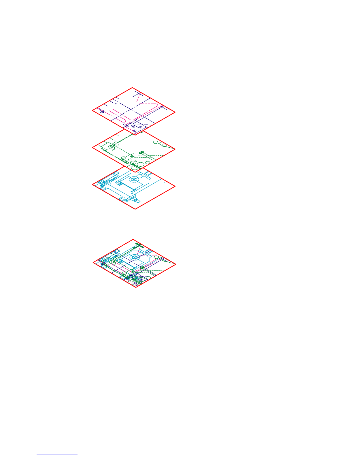
Organize Drawing Information
In both manual drafting and CAD, you need a way to organize your drawing
content—a method for separating, sorting, and editing specific drawing data.
With manual drafting, you can separate
information onto individual transparent
overlays. For example, a building plan
might contain separate overlays for its structural, electrical, and plumbing components.
In AutoSketch, layers are equivalent to transparent overlays. As with overlays, you can
display, edit, and print layers separately or
in combination.
You can name layers to help track content,
and lock layers so they can’t be altered.
Assigning settings such as color, pen style,
or pen width to layers helps you comply
with industry standards.
Turn off layers to hide complex
details as you work.
Display layers when you need
to see all components.
You can also use layers to organize drawing
objects (called entities in AutoSketch) for
printing.
This mechanical drawing of a press uses layers to show different types of information in
different styles and colors.
Organize Drawing Information | 9
Page 16
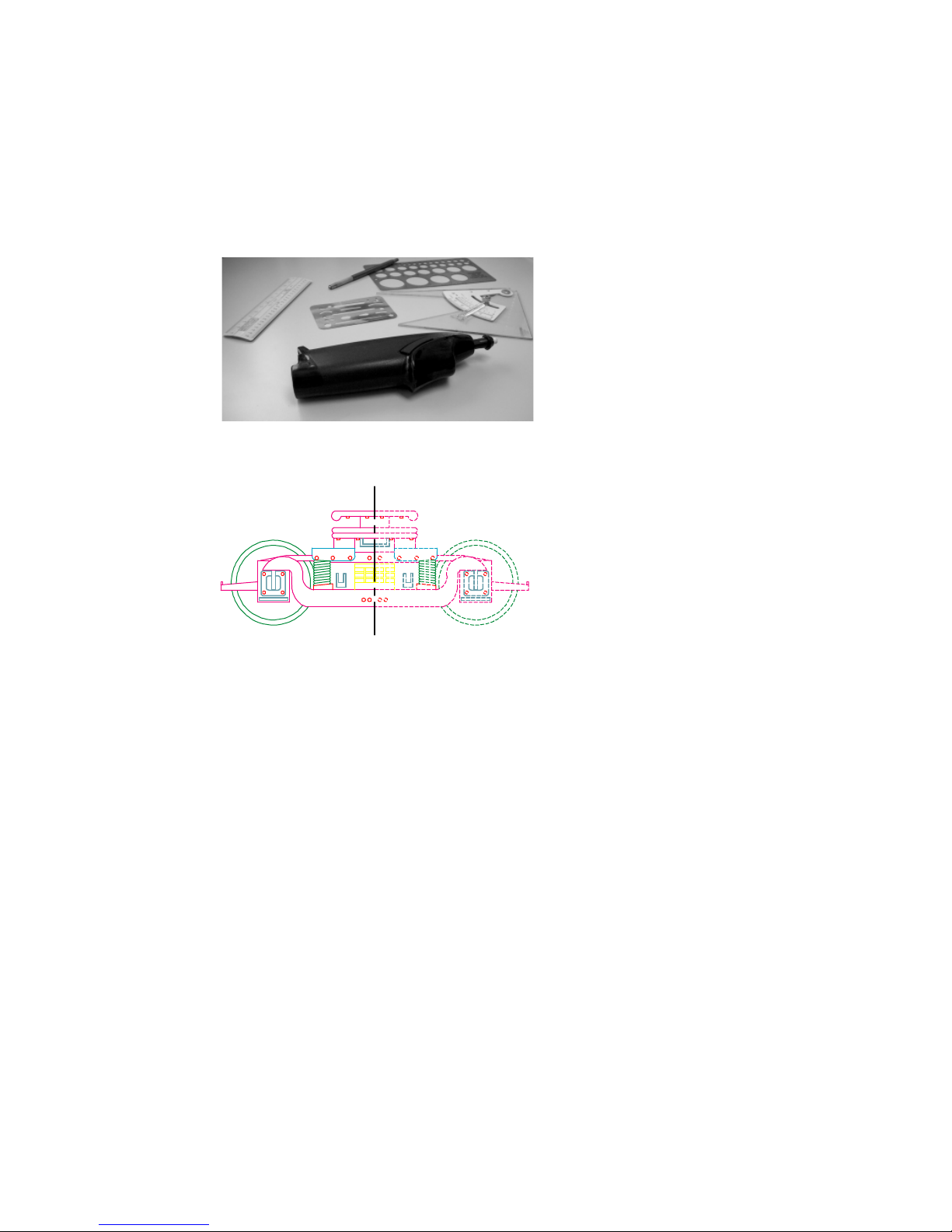
Draw Efficiently
Draw with less effort and revise with more speed: these are the two main
reasons you use CAD. AutoSketch has a complete set of drawing and editing
tools to help eliminate repetitive, time-consuming drafting tasks.
You can save drafting time by drawing one
half of an item and then mirroring it to create
the other half.
If you work with paper and a
drawing board, your set of drawing tools is likely to include
pencils, scales, parallel rules,
templates, and erasers. Repetitive
drawing and editing tasks must be
done manually.
In AutoSketch, you can choose
from a variety of drawing tools
that create lines, rectangles, circles, curves, and more.
With AutoSketch, you can easily
copy, scale, rotate, and mirror
entities. You can move or copy
entities between open drawings or
within the same drawing. Editing
is easy with tools such as stretch,
align, and offset. To add hatching,
simply insert a hatch pattern from
the AutoSketch Content Librarian
into the area to be filled.
In this drawing of a trolley, copying and mirroring were used to create
repeated and symmetrical features. Offsetting lines and hatching were also
used to draw more efficiently.
10 | Chapter 2 Make the Transition from Paper to CAD
Page 17
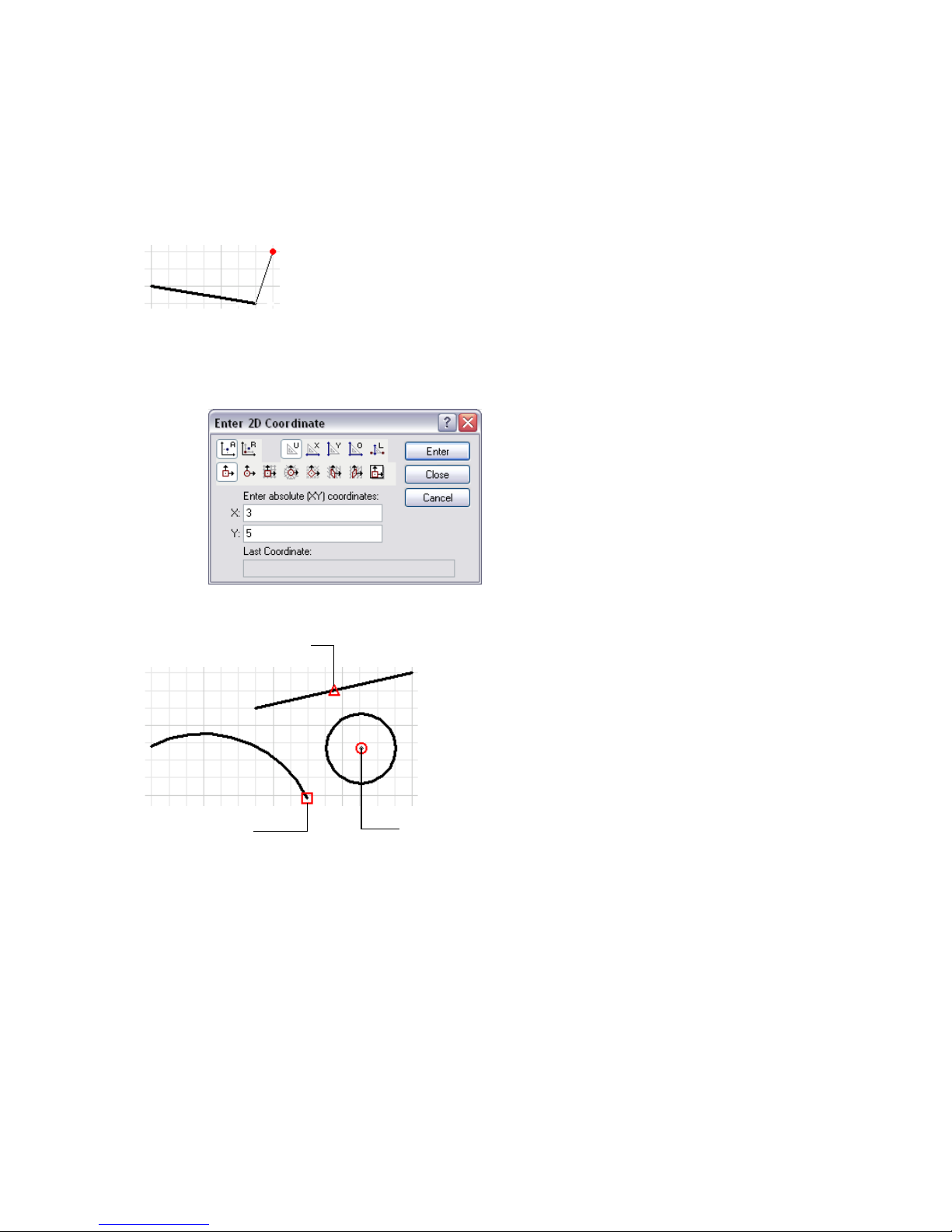
Draw Accurately
Engineering and architectural drawing require a high degree of accuracy.
With CAD, you draft more accurately than with manual methods.
Midpoint Snap
Snaps allows you to draw
with precision.
On paper, you must draw objects carefully to ensure correct size and
alignment. Objects drawn to scale must
be manually verified and dimensioned.
In AutoSketch, you can ensure exact
dimensions by using several methods.
The simplest method is to locate points
by snapping to some interval of a grid.
Another method is to specify exact
coordinates. Coordinates specify a drawing location by indicating a point along
an X and Y axis or a distance and angle
from another point. You can specify
coordinates that are relative to other
points or to the drawing’s coordinate
system.
You can also snap to locations on existing entities, such as an endpoint of an
arc, the midpoint of a line, or the centerpoint of a circle.
Endpoint Snap Centerpoint
Snap
Draw Accurately | 11
Page 18
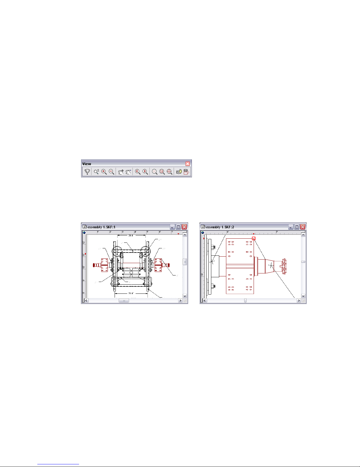
View Your Drawing
The power of CAD makes it easy for you to quickly view different parts of
your design at different magnifications.
When you draft on paper and need to work on another section, you must
physically move to that area of your drawing.
In CAD, the size and resolution of your computer monitor limit your viewing
area. AutoSketch viewing methods bypass this limitation.
To do detailed work, you can increase display size by zooming in. You can
zoom out to display more of the drawing. To move to another section of a
drawing, you pan the drawing without changing magnification.
You can view several areas of your drawing simultaneously by creating additional windows. Windows can be arranged automatically or manually. They
let you work easily on different parts of your drawing. Changes in one
window are reflected in the others.
Windows display different portions of your drawing simultaneously. You can zoom
and pan the display in each window independently
With detail views, you can arrange additional views at different zoom levels
or scales. You can create split windows, and you can pan and zoom in each
window to create the best working conditions.
12 | Chapter 2 Make the Transition from Paper to CAD
Page 19
Modify Your Drawing
Revisions are a part of any drawing project. Whether you work on paper or
with CAD, you will need to modify your drawing in some way.
On paper, you must manually erase and
redraw to make revisions to your drawing.
AutoSketch eliminates tedious manual editing
by providing a wealth of editing tools. If you
need to copy all or part of an entity, you don’t
have to redraw it. If you need to remove an
entity, you can erase it with a few clicks of the
mouse. And if you make an error, you can
quickly undo your actions.
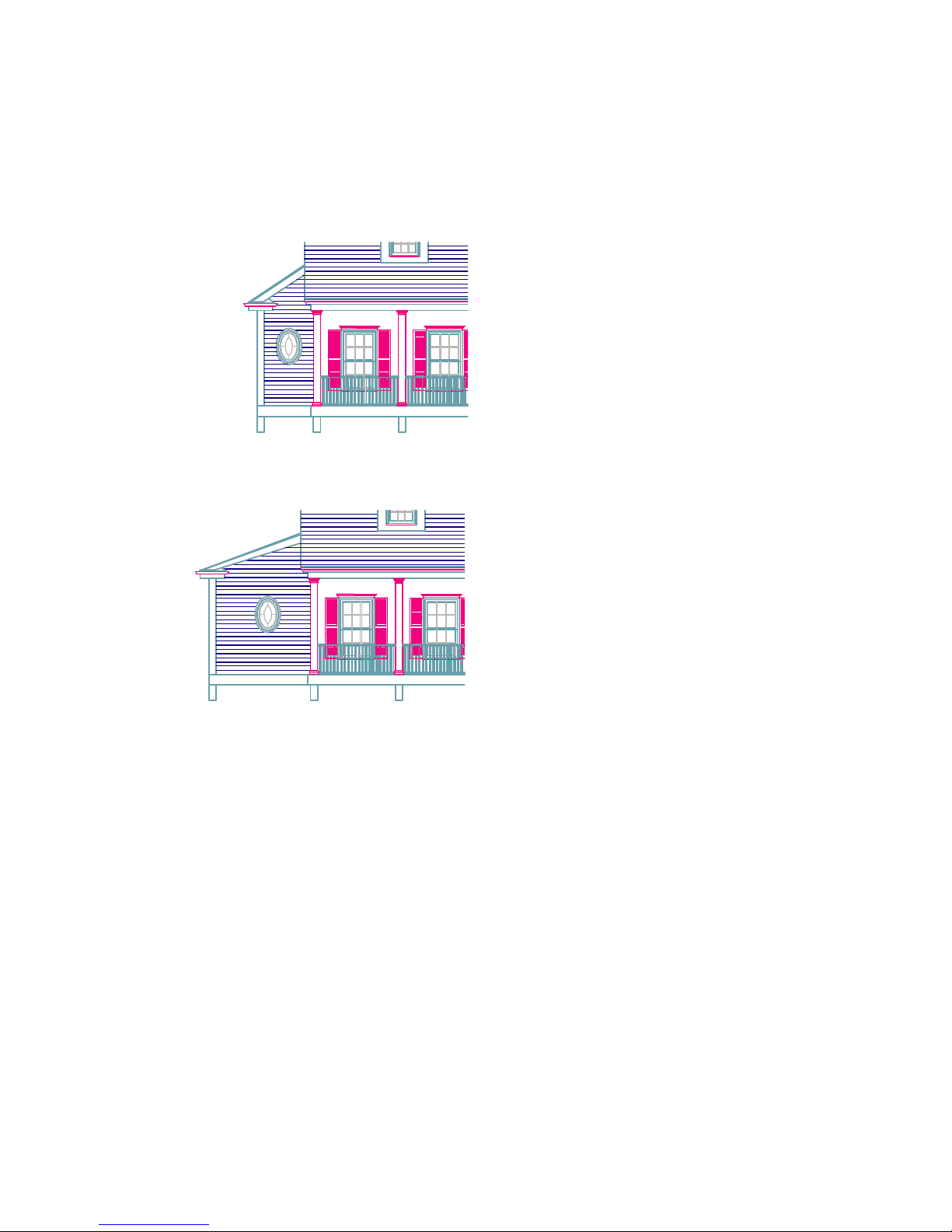
If you stretch an entity...
...the hatch adjusts automatically.
Once you draw an entity, you never need to
redraw it. You can modify existing entities by
mirroring, rotating, scaling, stretching, trimming, and more. At any time, you can change
entity properties, such as pen style, pen width,
color, and layer.
These before-and-after drawings show some
typical edits to a house elevation.
Modify Your Drawing | 13
Page 20
Use Standard Symbols
Symbols have long been used in manual drafting as a way to represent realworld objects in a simplified way. The ability to create and reuse standard
symbols is one of CAD’s greatest strengths.
With manual drafting, you might use a
symbol template or printed stickers to
draw repetitive landscape, architectural,
mechanical, or electrical symbols. This
method, however, limits the possible
variations of a symbol.
In AutoSketch, you can save time by
inserting symbols from the Content
Librarian anywhere in your drawing, at
any rotation or scale.
You c an th en ad d a sy mb ol as many ti me s
as needed by simply clicking to place the
symbol.
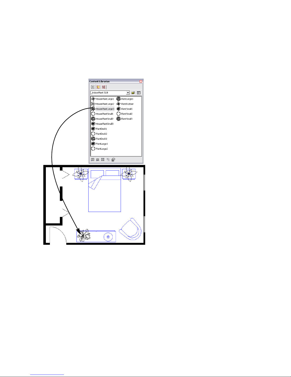
The Content Librarian lets you locate libraries
(collections) of symbols. You choose the symbol
you want and drag it into your drawing.
Should a standard symbol change (be
redefined), all instances of the symbol in
your drawing will automatically be
replaced.
In AutoSketch, you can also create your
own symbols from scratch or modify
existing ones.
Standard landscaping symbols are used
in this drawing of a residential home
floor plan.
14 | Chapter 2 Make the Transition from Paper to CAD
Page 21
Create Dimensions and Text
Creating accurate dimensions and consistent, legible text is a time-consuming task for the manual drafter. CAD provides ways to streamline this task.
When you work on paper, you typically
draw to scale and then add dimensions
and annotations. If you resize any part
of the drawing, you must erase and
then redraw the dimensions. Changing
text can often involve relettering the
whole drawing. AutoSketch automates
the process of creating and changing
dimensions and text.
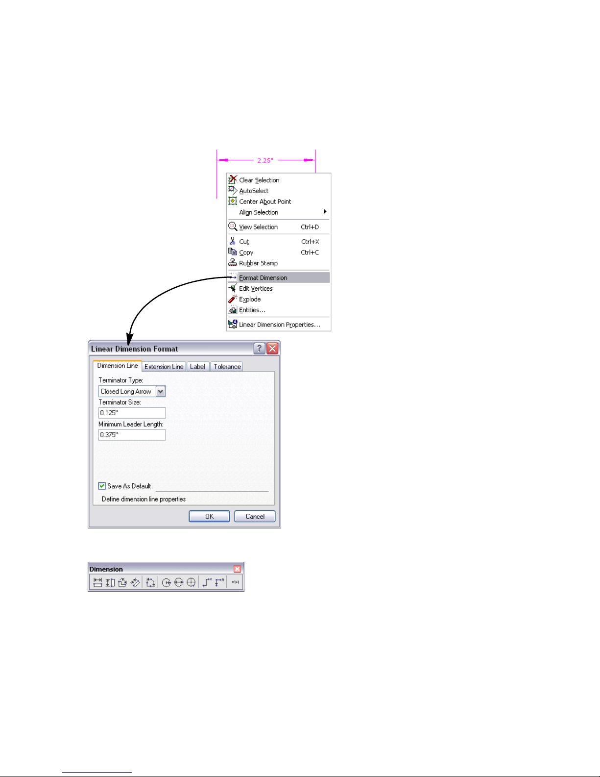
In AutoSketch, you can customize
individual dimensions, and when
information changes, you can easily
revise text, including its content, font,
height, angle, and justification.
Virtually all standard dimensioning
types are provided in AutoSketch:
linear, radial, ordinate, angular, baseline, and more.
Create Dimensions and Text | 15
Page 22

16
Page 23
AutoSketch Basics
3
In this chapter, you learn how to start AutoSketch® and
use the Startup dialog box to create or open a drawing.
You also learn about the user interface and the basic
features and functionality of AutoSketch. Once you
have learned these AutoSketch “basics,” you can do the
exercises in this guide’s tutorials and learn to use the
product.
More information about each of these components and
features is available in the Help system.
In this chapter
■ Introduction
■ Start AutoSketch
■ Use the Start Up Dialog Box to
Create or Open a Drawing
■ Understand the User Interface
■ Basic Features and Functionality
17
Page 24

Introduction
AutoSketch is a precision drawing tool for the Microsoft® Windows® XP and
Windows® 2000 operating systems. The emphasis in AutoSketch is on speed,
power, and ease of use.
AutoSketch features appear when you need them, and are kept out of the way
when you don’t. If you’re already a Windows 2000 or Windows XP user,
you’ll find the menu system and much of the user interface familiar. If you’re
new to Windows, you’ll find AutoSketch an easy place to work.
In this chapter, you learn how to start AutoSketch and use the Start Up dialog
box to create or open a drawing, and you get familiar with the user interface
components.
Start AutoSketch
When you start AutoSketch, you can begin a new drawing, start with a
template, or open existing drawings. Simply click a selection and begin.
To start AutoSketch for the first time
■ On the Start menu (Windows), click All Programs (or Programs) ➤
Autodesk AutoSketch 9.
The AutoSketch Start Up dialog box is displayed.
Use the Start Up Dialog Box to Create or
Open a Drawing
The Start Up dialog box has three tabs with options for starting a drawing:
■ Wizard tab. Allows you to start a drawing immediately or choose one of
the listed wizards.
■ Template tab. Allows you to base a drawing on a template, and to preview
and organize the templates.
■ Open tab. Allows you to open a recently used file, browse for a file, and
preview a selected file.
18 | Chapter 3 AutoSketch Basics
Page 25
Start a Drawing or Choose a Wizard (Wizard
Ta b )
In the Start Up dialog box, Wizard tab, you can start a drawing immediately
or choose a wizard to start a drawing.
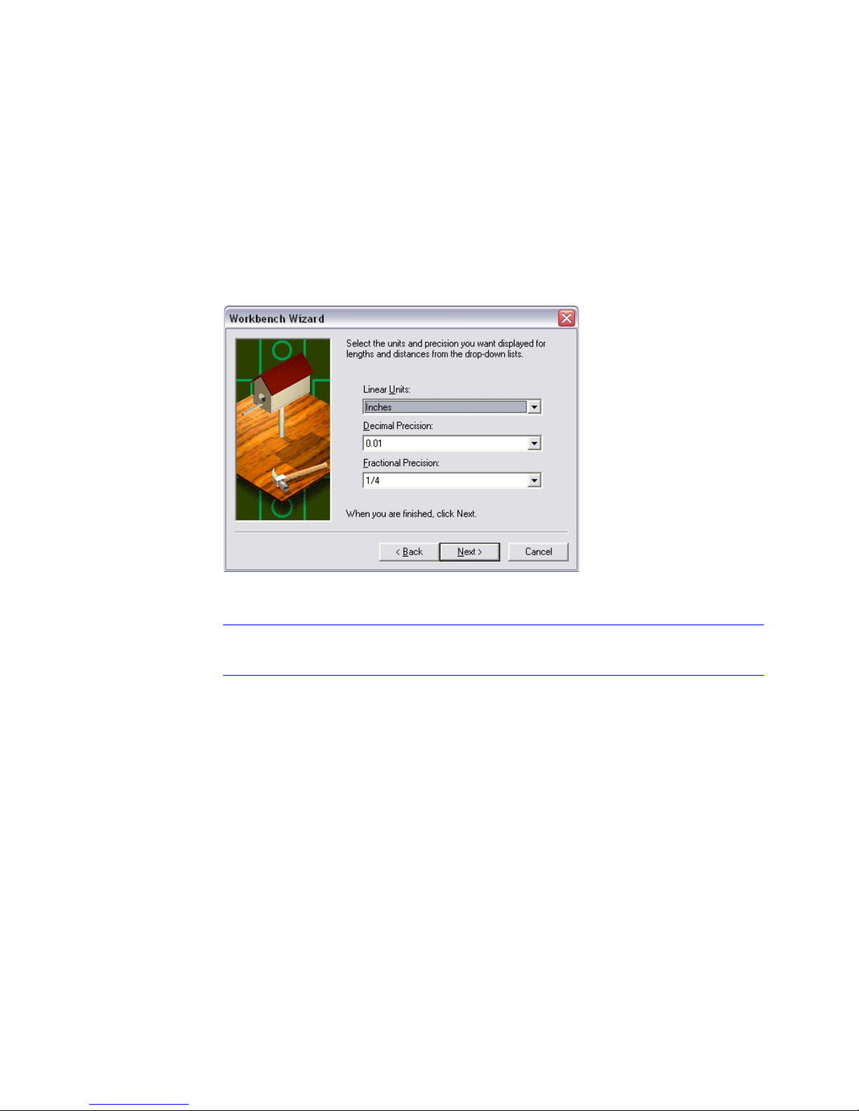
A wizard contains instructions to guide you through the steps to accomplish
a task. The AutoSketch Start Up wizards help you make drawing decisions to
set up a drawing. If you are drawing a workbench project, for example, the
wizard steps you through logical workbench decisions for that drawing.
Example of a page in the Workbench wizard
Tip During an AutoSketch work session, you can access wizards by clicking
File ➤ New.
The illustration shows the Wizard tab, and is followed by an explanation of
each of its choices.
Use the Start Up Dialog Box to Create or Open a Drawing | 19
Page 26
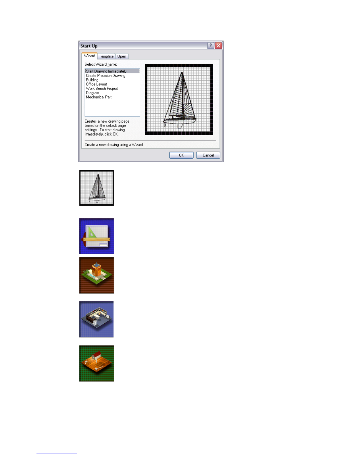
Start a Drawing Immediately. Creates a new drawing based on
preset settings such as page size and scale. You can always
change these settings later. Select this option, and then click
OK. You are ready to begin drawing.
The following choices on the tab are wizards:
Create Precision Drawing. Creates a new drawing based on
settings that you specify. You enter summary information
(including drawing title, project name, and so on), drawing size
and scale, units of measurement, and grid spacing
Building. Sets up a drawing of a commercial building, home, or
exterior site layout. You choose the building shell, dimensions,
wall thickness, roof generation, database report types and
fields, layers, page orientation, and useful toolbars. You can
add symbols such as telephone poles, trees, and hydrants.
Office Layout. Sets up a drawing of a single office or an entire
floor of offices. You choose the office shell, dimensions, wall
thickness, database report types and fields, layers, page orientation, grid settings, and useful toolbars. You can add symbols
such as telephones and computer equipment.
20 | Chapter 3 AutoSketch Basics
Work Bench Project. Sets up a drawing of a small home, or a
mechanical or woodworking project. You specify page orientation, units and precision, scale, grid options, database report
types and fields, layers, and useful toolbars.
Page 27
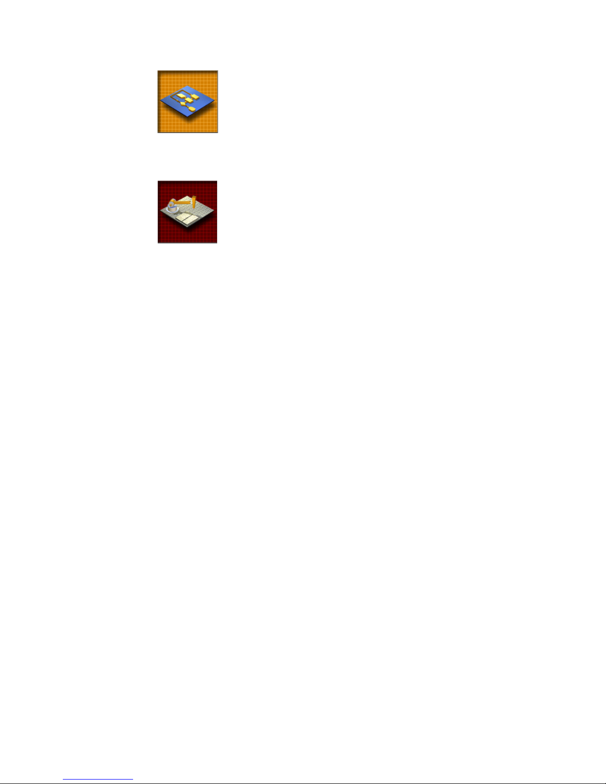
Diagram. Sets up a diagram such as organizational tree, Web
site map, flow chart/schedule, piping, electronic schematic,
logic diagram, networking, or PC board layout. You choose the
type of diagram, page orientation, and useful toolbars.
You can add symbols such as flowcharts, schedules, piping,
switches, capacitors, lamps, switchboxes, PCs, printers, mainframes, modems, circuit chips, soldering points, and so on.
Mechanical Part. Sets up a drawing of a small machine or
machine component. You specify page orientation, units, precision, scale, annotation options, Edit command settings, grid
options, page division (for different views of a part), database
reports and fields, layers, and useful toolbars. You can add symbols such as nuts, bolts, screws, brackets, washers, and so on.
Choose a Template (Template Tab)
In the Start Up dialog box, Template tab, you can choose a template file to
start a drawing.
AutoSketch includes dozens of drawing template files. A template is a drawing file that has settings such as borders, title blocks, grid spacing, drawing
scale, and page size already selected for you. When you select one of the templates in the list, you can preview it in the Preview area. Then, you simply
choose the template that is right for your project.
You can also create your own template from an existing drawing. If you
create the same type of drawing each time you work with AutoSketch, you
may want to redefine the default template by saving an existing drawing as
a template, and then selecting that template as the new default. Then, you
can use the template to create new drawings of the same type.
The following illustration shows the Template tab.
Use the Start Up Dialog Box to Create or Open a Drawing | 21
Page 28

Tip During an AutoSketch work session, you can access templates by clicking
File ➤ New.
Open an Existing Drawing (Open Tab)
In the Start Up dialog box, Open tab, you can open an existing drawing file.
You can adjust how files are displayed in the list, browse for more files, and
preview a selected file.
The following illustration shows the Open tab.
22 | Chapter 3 AutoSketch Basics
Page 29

Tip During an AutoSketch work session, you can access existing drawings by
clicking File ➤ Open.
Understand the User Interface
The first step in learning how to use AutoSketch is to become familiar with
its user interface.
Drawing Window
Once you choose the type of drawing you want to create, AutoSketch opens
a drawing window. The drawing window in AutoSketch is the space where
you work.
Many drawing windows can be open at one time. Clicking a drawing window
makes it active so that you can work in it. You can make changes in the active
window only. You can resize, minimize, maximize, and close each drawing
window independently.
The following illustration shows the AutoSketch user interface elements in a
drawing window. These elements are listed alphabetically and described after
the illustration.
Understand the User Interface | 23
Page 30
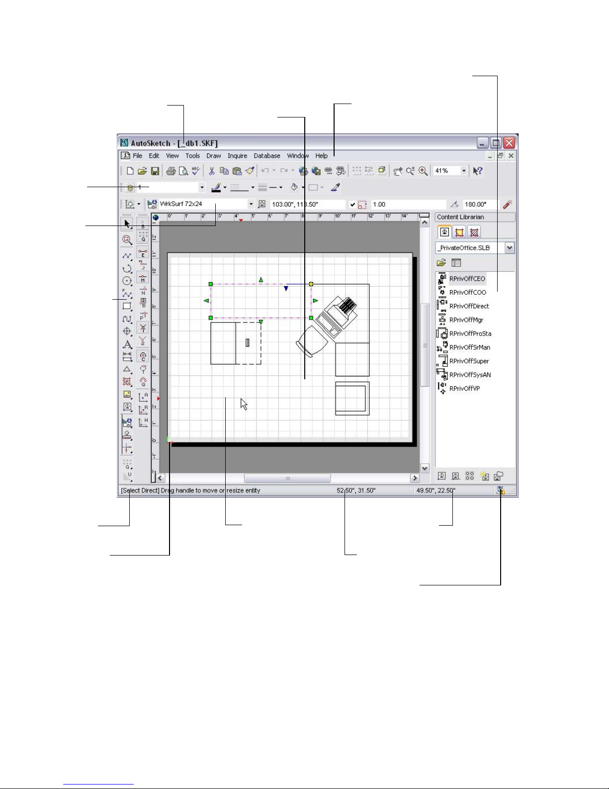
Property
Bar
Edit
Bar
All-In-One
Too l b ar
Title Bar
Drawing
Window
Content
Librarian
Menu Bar
Status
Bar
Drawing
Origin
Reference
Grid
Relative Coordinates
Dial
Absolute Coordinates
Dial
Communication
Center
24 | Chapter 3 AutoSketch Basics
Page 31

All-In-One Toolbar
As its name suggests, the All-In-One toolbar contains buttons that help you
perform most of the tasks that you need to do to create a drawing. Take a few
moments to understand how this toolbar works before doing the exercises in
this guide.
Most of the buttons on the AutoSketch specialized toolbars can be found on
the All-In-One Toolbar. For example, the All-In-One toolbar contains all of
the 15 snap tools on the Snap toolbar. Simply click and hold the Snap to Grid
button on the All-In-One toolbar, and the other Snap tools are displayed on
the toolbar that appears, called the toolset. To display a tooltip for any toolbar
button on a toolset, keep the mouse button depressed and place your pointer
over the button. To select a button, release the mouse button.
In the exercises in this guide, you are instructed to use the Draw menu, the
All-In-One toolbar, and other toolbars to complete the tasks. You may find
that many of the same tasks can be performed by using different toolbars
included in AutoSketch. You can learn more about those toolbars in the Help
system.
Note The following table shows the buttons that are displayed on the All-In-
One toolbar when you first use AutoSketch. When you click a button on a
toolset, that button “sticks,” or remains the active button, until you click a different button on the same toolset.
All-In-One Toolbar buttons
Toolbar
button
Button name Description
Select Selects one or more entities. The Select toolset has
these buttons: Select Direct; Select All; Modify
Selection; Select Inside Polygon; Select Fence; Clear
Selection; Marquee; Irregular Marquee; and Clear
Marquee.
Zoom Gets a closer view of a portion of your drawing. The
Zoom toolset has these buttons: Redraw; Zoom
Realtime; Zoom In; Zoom Out; Pan Realtime; Pan;
Last View; Next View; View Selection; View Page;
View Extent; View Save; View Recall.
Understand the User Interface | 25
Page 32

All-In-One Toolbar buttons (continued)
Toolbar
button
Button name Description
Line Draws lines and line variations. The Line toolset has
these buttons: Line Single; Line Segment; Line
Multiple; Line Double; Line Tangent; Line
Perpendicular; Line Angle.
Arc Draws circular arcs and elliptical arcs. The Arc
toolset has these buttons: 3 Point Arc; 2 Points and
Center Arc; 2 Points and Angle Arc; Elliptical Arc
Rectangle; Elliptical Arc Axes.
Circle Draws circles and ellipses. The Circle toolset has
these buttons: Center, Side Circle; Side, Side Circle;
3 Point Circle; Center, Radius Circle; Circle Tangent
2; Circle Tangent 3; Ellipse Rectangle; Ellipse Axes.
Polyline Draws polylines. The Polyline toolset has these
buttons: Single Polyline; Polyline Segment;
Perpendicular Polyline; Center Polyline; Sketch
Polyline.
Polygon Draws polygons. The Polygon toolset has these
buttons: Rectangle; Rotated Rectangle; Regular:
Center, Edge; Regular: Edge, Opposite; Regular:
Edge, Adjacent; Regular: Center, Radius; Irregular
Polygon; Irregular Cloud.
Curve Draws fitted and spline curves. The Curve toolset
has these buttons: Fitted Curve; Spline Curve.
Marker Marks points in your drawing. The Marker toolset
has these buttons: Marker Point; Marker Align
Entity; Marker Align Endpoint.
Text Enters a line or paragraph of text in your
drawing.The Text toolset has these buttons: Text
Point; Text Rectangle.
Dimension Draws dimension lines. The Dimension toolset has
these buttons: Horizontal Dimension; Vertical
Dimension; Rotated Dimension; Aligned
Dimension; Angular Dimension; Radius Dimension;
Diameter Dimension; Centerline Dimension;
Ordinate Dimension; Leader.
Duplicate Creates a duplicate of a selected entity and places it
at a specific offset distance. The Duplicate toolset
has these buttons: Parallel; Offset.
26 | Chapter 3 AutoSketch Basics
Page 33

All-In-One Toolbar buttons (continued)
Toolbar
button
Button name Description
Fill Creates hatches (a repetitive line pattern in an
enclosed area defined by a selection set). The Fill
toolset has these buttons: Fill Hatch; Fill Solid Color.
Picture/Detail View Inserts bitmap pictures or detail views into the
drawing. The Picture/Detail View toolset has these
buttons: Picture From File; Detail View.
Symbol Manages, creates, places, and duplicates symbols in
a drawing. The Symbol toolset has these buttons:
Symbol Point; Insert Symbol; Symbol Array; Create
Symbol.
Inquire Displays information about a drawing and its
entities. The Inquire toolset has these buttons:
Inquire Entity; Inquire Symbol Count; Inquire
Selection; Inquire Drawing; Inquire Coordinate;
Inquire Distance; Inquire Angle; Inquire Area.
Transform Moves, scales, rubber-stamps, or rotates entities.
The Transform toolset has these buttons: Rubber
Stamp; Rubber Stamp Array; Translate; Scale;
Rotate; Align; Mirror; Stretch; Rectangular Array;
Circular Array.
Trim Edits the geometry of entities. The Trim toolset has
these buttons: Trim Corner; Trim Round; Trim Bevel;
Trim Edge; Trim Break; Trim Channel; Trim Divide;
Trim Subdivide; Trim Join; Trim Alcove; Trim Union;
Trim Intersection; Trim Difference
Snap Snaps to a point on the grid. The Snap toolset has
these buttons: Snap Off; Gridpoint Snap; Endpoint
Snap; Jump Snap; Midpoint Snap; Nearest Snap;
Basepoint Snap; Perpendicular Snap; Intersection
Snap; 2 Point Intersection; Centerpoint Snap;
Tangent Snap; Quadrant Snap; Absolute Input;
Relative Input; Set Last (Working) Point.
Lock Turns lock modification on and off. The Lock toolset
has these buttons: Unlock; Lock X; Lock Y; Ortho
Lock; Normal Lock.
Understand the User Interface | 27
Page 34

Communication Center
Displays product announcements, product support information, and articles
and tips of interest. You can learn how to use Communication Center in “Use
the Communication Center” on page 104.
Content Librarian
Contains symbols, fill colors, and hatches that you can insert into a drawing.
If a wizard was used to create a drawing, the Content Librarian provides
symbol libraries specific to that wizard.
The Content Librarian with the _DoorOffice symbol library displayed
Edit Bar
When active, allows you to edit geometric properties of an entity. The function of the edit bar changes depending on the task you are doing. For
example, if you select text in the drawing, the controls on the edit bar allow
you to edit the text, font, height of the text, and so on.
The edit bar when text is selected in a drawing
28 | Chapter 3 AutoSketch Basics
Page 35

Menu Bar
Displays a list of menus and their options. You can also use toolbars and
shortcut keys on the keyboard (CTRL+<letter>) to perform the same tasks.
The menu bar
Property Bar
Sets the current layer, color, style, width, and pattern. Any change you make
on the property bar affects entities that are currently selected, and those that
you draw in the future.
The property bar
To change a setting on the property bar, click the small arrow to display the
list of properties, and make a new selection. To apply a new setting to an
entity, select the entity you want to change, and then click the property setting on the property bar.
Status Bar
Displays a message area on the left side and the coordinates dials on the right.
The message area displays prompts, messages, and step-by-step instructions
for most procedures.
The status bar
Two dials occupy the right side of the status bar. The Absolute Coordinates
dial (on the left side) displays the absolute location of the point (its position
in relation to the drawing origin). The Relative Coordinates dial (on the right
side) displays the relative location of the point (its position in relation to the
last point entered).
Understand the User Interface | 29
Page 36

Title Bar
Displays the name of the program and the name of the current drawing file.
The AutoSketch title bar extends across the top of the application window.
The title bar
To o l b a r s
Provide buttons that allow you to do drawing tasks. (You can also use menus
to perform the same tasks.) When a toolbar button has a triangle in its lowerright corner, you can click and hold the button to access additional items,
called toolsets.
The All-In-One toolbar with the Circle toolset displayed
You can move a toolbar by clicking near its left edge and dragging it to its
new location. You can also place toolbars next to one another and dock them
in the drawing window.
To o l t i p s
Display the name or the function of toolbar buttons. Hold your pointer over
a tool to display its tooltip.
Example of a tooltip
To display a more detailed explanation of the tool, click the Help button (on
the Standard toolbar), and then click a toolbar button.
30 | Chapter 3 AutoSketch Basics
Page 37

Example of detailed Help for a tool
Basic Features and Functionality
Before you use AutoSketch, there are important features and functionality
that you should understand. Understanding the concepts in the following
sections is the key to a successful experience of doing this book’s exercises. It
is strongly recommended that you read this material carefully. Each concept
is briefly defined here and described in detail afterward.
■ Entity. A single object, such as a line, polygon, or symbol.
■ Properties. An item of information assigned to an entity. Properties
include geometry, layer, pen, pattern, and so on.
■ Scale. The ratio between the size of an entity in its scaled output and the
size of the real-world object it represents. For example, if an entity that is
1/4 inch long in its scaled output represents a real-world object that is 1
foot long, the drawing scale is 1/4"=1'0".
■ Coordinates. A pair of numbers that together specify the location of a
point in your drawing.
■ Drawing Origin. The point that serves as a location reference for all
entities in the drawing. The x- and y-axes cross at the drawing origin. The
coordinates of the drawing origin are 0,0.
■ Reference Grid. An on-screen drawing aid consisting of a snap grid and a
pattern of lines, crosses, or dots that visually represent the grid.
■ Grid Origin. The point from which the axes of the reference grid extend
outward.
■ Snap. A means of entering points using the mouse or keyboard. You can
change the snap at any time during most Draw and Edit operations by typing the appropriate keyboard shortcut.
■ Lock Modifiers. Four modifications that you can apply to a snap. Lock
modifiers align input with the last point and are applied after the snap.
For detailed information about these concepts, see the Help system.
Basic Features and Functionality | 31
Page 38

Entities
Entities are the fundamental elements of a drawing. They can be simple (base
entities), such as a single line, arc, circle, or polyline, or they can be groups
of drawing elements (compound entities), such as symbols and dimensions.
Entities can also be other elements in your drawing, such as pictures or
elements from other drawings. Most entities can be edited. You can resize
them and change their properties.
The following table lists the type of entities that you can create in
AutoSketch.
Entity Description
Arc A portion of a circle. You can use an arc to show a rounded wall,
the direction a door swings, and so on.
Circle A curved line with every point equally distant from the center. You
can use a circle to represent a hole, a round object, and so on.
Curve A polyline that is rendered onscreen and on printed output in a
special way. Use curves to create free-form shapes such as curved
sidewalks and car fenders.
Detail view A rectangular area that displays another portion of the drawing
defined by a previously saved view.
Dimension A predefined collection of lines, arcs, markers, and text that display
a measurement in the drawing. The text label is updated
automatically when you stretch or reshape the dimension.
Ellipse A closed symmetrical curve that resembles a flattened circle.
Fill A hidden-line polygon that conforms to the shape of a bounded
area and displays either a solid color, a hatch, or a bitmap fill.
Group A compound entity consisting of individual symbols and entities
that AutoSketch treats as a single entity.
Line An entity that connects two points. You can use a line to represent
any straight object such as a water pipe, a wall edge, an electrical
connection, or a street.
Marker An entity that notes a specific point in a drawing.
32 | Chapter 3 AutoSketch Basics
Page 39

Entity Description
OLE Object An entity that is created in one application and embedded in
another. When you double-click a linked OLE object, Windows
opens the source application that created it and loads the
associated file.
Picture A picture or bitmap that can be imported and placed in the
drawing. AutoSketch treats the raster image like most other
entities, allowing you to move, scale, or duplicate the image as
needed.
Polygon A closed polyline that can contain a fill pattern. Use a polygon
when you need to know the area of an enclosed region or when
you need to fill an area with a solid color, a hatch, or a bitmap fill.
Polyline A multi-segmented line that AutoSketch treats as a single entity.
When a polyline is closed, it becomes a polygon. Use a polyline
when you need to know the total length of a series of connected
segments.
Symbol A group of entities that AutoSketch treats as a single entity.
Symbols can be stored in libraries for use in multiple drawings.
Text A text entity that can be any size, can use any TrueType font, and
can be rotated at any angle.
Properties
Properties are the individual qualities that define an entity. They are divided
into three categories:
■ Geometric properties define an entity’s size, position, and so on.
AutoSketch assigns geometric properties automatically as you draw and
edit.
■ Graphic properties specify the appearance of an entity. Graphic properties
include layer, color, width, style, and pattern. AutoSketch assigns these
properties as you draw, based on the current settings on the property bar.
■ Fields customize an entity in ways that you define. Define a field by spec-
ifying its name, type, and width or precision. A desk symbol, for example,
can have fields for model, size, color, and style.
Basic Features and Functionality | 33
Page 40

Scale
Drawing scale is the ratio between the actual size of the entities in a drawing
and their size on printed output. In conventional drafting, you scale the
components of a drawing by using an architectural or engineering scale. In
AutoSketch, you simply enter the actual (world) size of an entity, and the
software keeps track of the scale for you.
You can create 1:1 drawings in AutoSketch without regard for scale. Specifying a drawing scale, however, has two important benefits. It allows
AutoSketch to accurately depict how your drawing will look on a printed
page. It also allows you to specify entities such as text, markers, and dimensions by output size.
Any output you plan to measure with an architectural or engineering scale
must be printed to scale. When you create scaled output, you can print the
entire drawing or a portion of the drawing. The scale used when printing is
the current drawing scale.
Coordinates
Coordinates are numbers that specify the location of one point in relation to
another. This relationship is classified as either absolute or relative.
Absolute coordinates reference the origin of whatever coordinate system is
currently being used (for example, the drawing origin or the grid origin).
Relative coordinates reference the last point you entered. They are useful
when you want to draw or place another entity a known distance from
another entity or point.
AutoSketch expresses location in three ways: xy (Cartesian), polar, and
isometric coordinates. X- and y-coordinates express location in terms of
horizontal and vertical distances from another point. Polar coordinates
express location in terms of distance (radius) and angle. For example, the xy
coordinates 7,5 are equivalent to the polar coordinates 8.6,35.5.
Isometric coordinates add a third axis (z) to the expression. Isometric drawings are often used to create two-dimensional views of a three-dimensional
object.
34 | Chapter 3 AutoSketch Basics
Page 41

Examples of coordinates
Drawing Origin
The drawing origin displays the x (horizontal), y (vertical), and (if isometric)
z coordinates of a drawing. AutoSketch locates most points in relation to the
drawing origin.
The drawing origin is shown on screen as colored arrows.
Example of the drawing origin arrows in the lower-left corner of a drawing
If you move the drawing origin, the entire drawing shifts to reflect that
change. The drawing origin does not appear when you print the drawing.
Normally, the drawing origin is located at the lower-left corner of a drawing.
If you need to move it, you can center the drawing origin or relocate it.
Basic Features and Functionality | 35
Page 42

Reference Grid
A reference grid is a visual drawing aid that contains a pattern of horizontal
and vertical lines or dots that represent a grid. Use gridpoint snaps to make
your drawing precise.
Example of a first point snapping to a grid
There are three types of reference grids available in AutoSketch, each suited
for different purposes.
■ The default grid is rectangular, with snap intervals and lines that parallel
the x- and y-axes. This grid is the standard reference tool for most twodimensional drawings.
■ Circular grids extend radially from the grid origin. They provide an excel-
lent reference tool for drawings that require alignment of points along an
arc or circle, such as a mechanical drawing of a gear.
■ Isometric grids align along three major axes, instead of two. This allows
you to create two-dimensional drawings of three-dimensional objects.
You can modify the settings for each of the reference grids.
The following table lists the Grid tools you can use in AutoSketch. These
buttons are located on the Grid toolbar.
Toolbar
button
Button name Description
Rectangular The most commonly used, is useful for most two-
dimensional drawings.
Circular Aligns grid lines along an arc or circle. The radial grid
lines allow you to enter such points precisely. When you
set up a circular grid, you may need to reposition the
grid origin so that the radial lines of the grid are aligned
correctly on the page.
Isometric Top Aligns snap and grid lines along 30- and 150-degree
axes.
36 | Chapter 3 AutoSketch Basics
Page 43

Toolbar
button
Button name Description
Isometric Left Aligns snap and grid lines along 90- and 150-degree
axes.
Isometric Right Aligns snap and grid lines along 90- and 30-degree
axes.
Double Grid Size Doubles the current grid size.
Halve Grid Size Decreases the current grid size by half.
Tip You can also change settings using the Edit Grid button on the Standard
toolbar.
Grid Origin
The grid origin is similar to the drawing origin in function and appearance.
However, the grid origin serves as a reference point for grid coordinates only.
By default, the grid origin is located at the drawing coordinates 0,0. You can
move the grid origin of rectangular, circular, or isometric reference grids.
Snap
Using snap, you can draw with real precision by identifying exact points such
as an entity’s midpoint, endpoint, or centerpoint. These points are called
snap points because when you click near one, the point is snapped to the
exact point shown.
There are 15 ways to snap to a point in AutoSketch. These correspond with
the 15 snaps you can choose by clicking their buttons on the All-In-One toolbar, Snap toolbar, or by typing the letter shown on the button.
Basic Features and Functionality | 37
Page 44

When snaps are active, a red AutoPoint Indicator is displayed on the grid. As
you move the pointer over a drawing, each type of snap point displays a
different symbol. (You may notice these snap types when you create simple
entities in the first tutorial.) The following table lists the default snap types.
Symbol Snap Type Description
Gridpoint snap Snaps to the reference grid.
Endpoint snap Snaps to the endpoint of an entity.
Midpoint snap Snaps to the midpoint of a line, polyline
segment, etc.
Intersection snap Snaps to intersection points.
Centerpoint snap Snaps to the center of an arc, circle, polygon,
or bulged poly-segment.
Lock Modifier
You can align input with the last point by using a lock modifier. If a lock
modifier is active, a dotted line extends from the AutoPoint Indicator to the
actual point, as constrained by the lock modifier. For example, if you draw a
diagonal line from top to bottom, and then activate Endpoint snap and the
Y-axis lock modifier, the square AutoPoint Indicator identifies the endpoint
nearest the pointer, but a dotted line extends to the potential snap point
based on the current snap and lock modifier.
Example of a line drawn with endpoint snap and y-axis lock modifier turned on
There are four automatic modifications you can have AutoSketch make to
the point you enter. These lock modifiers force the point you enter into horizontal, vertical, orthogonal, or “normal” alignment with the last point. At
any time in the drawing or editing process, you can apply a lock modifier by
clicking its button on the All-In-One toolbar or by typing the letter shown
on the button.
38 | Chapter 3 AutoSketch Basics
Page 45

Tutorial 1 — Create and
Trim Entities
In this tutorial, you learn how to start AutoSketch®,
create a drawing, and create entities. You also learn how
to trim entities using several methods.
More information about each of the concepts in this
tutorial is available in the Help system.
In this tutorial
■ Start AutoSketch
■ Create Simple Entities
■ Create Lines
■ Create Other Simple Entities
■ Trim an Entity
39
Page 46

Start AutoSketch
In this exercise, you learn to
❒ Start AutoSketch.
❒ Create a drawing from scratch.
Note At the end of each exercise, you can take a break or move to the next
exercise. Be sure to save your work at the end of each exercise, because each subsequent exercise builds on the one before it.
To start AutoSketch
1 On the Start menu (Windows), click All Programs (or Programs) ➤
Autodesk AutoSketch 9.
2 In the Tip of the Day dialog box, read the tip and click Close.
To start a drawing
1 In the Start Up dialog box, Wizard tab, select Start Drawing Immediately.
2 Click OK.
40 | Tutorial 1 — Create and Trim Entities
Page 47

Create Simple Entities
In the exercises that follow, you become familiar with simple entities by
creating lines, arcs, circles, polygons, and polylines. While you create entities, you also become familiar with the AutoSketch drawing window and how
the menus and toolbars can be used to create entities. In a later tutorial, you
learn how to create useful drawings with entities and symbols. But for now,
have fun creating simple entities.
Create Lines
In this exercise, you learn to
❒ Create a single line, a multiline, and a double line.
❒ Create lines using the Draw menu and the All-In-One toolbar.
❒ Right-click a toolbar button to access related buttons on a toolset.
❒ Right-click a command to end it.
❒ Use the SHIFT key to select multiple entities.
❒ Delete entities.
A line is an entity that connects two points. You can use a line to represent
any straight object.
To create a line
1 In AutoSketch, on the File menu, click New.
2 In the New dialog box, click Start Drawing Immediately, and then click
OK.
3 On the Draw menu, click Line ➤ Single.
4 In the drawing window, click anywhere to create the startpoint of the line.
Then, click another point in the drawing window to create the endpoint.
Right-click to end the command.
Click a startpoint Click an endpoint Right-click to end
LINE command
Example of a line produced with the Line Single option
Create Simple Entities | 41
Page 48

You have just created a line, your first computer-drawn entity. Continue
to draw lines until you feel comfortable with the action. When you are
ready, you can create a line that has multiple points.
5 On the Draw menu, click Line ➤ Multiple.
6 In the drawing window, click anywhere to create the startpoint of the line.
Then, click another point in the drawing window to create a second line
point. Continue clicking to create additional points. When you are finished, right-click to complete the line.
Example of a line produced with the Line Multiple option
Now, use the All-In-One toolbar to create a line. When you click and hold
the Line button on the All-In-One toolbar, you see additional buttons
called toolsets. Hovering over a button displays a tooltip with the name of
the button. When you end the command, the new button is shown on the
toolbar. The last button used is what appears on the toolbar, until a new
button is used.
7 On the All-In-One toolbar, click and hold the Line button.
8 On the toolset, drag the pointer until you locate Line Double, and then
release the mouse button.
9 Click anywhere in the drawing to create the startpoint of the line. Then,
click another point in the drawing window to create a second line point.
Continue clicking to create additional points. When you are finished,
right-click to complete the line.
Example of a line produced with the Line Double option
You may want to clean up your drawing at this point so that you have room
to draw more entities.
42 | Tutorial 1 — Create and Trim Entities
Page 49

To delete entities
■ On the keyboard, press CTRL+A to select all entities in the drawing, and
then press the DELETE key.
Now that you understand how to create different kinds of lines using the
Draw menu and the All-In-One toolbar, you can create other entities.
Create Other Simple Entities
In this exercise, you learn to
❒ Create arcs, circles, polylines, and polygons.
❒ Select startpoints, midpoints, and endpoints.
❒ Use the All-In-One toolbar to create entities.
❒ Use the All-In-One toolbar to access toolset tools.
In this exercise, you create variations of an arc, a circle, a polyline, and a
polygon.
■ Arc. A segment of a circle defined by a centerpoint, radius, starting angle,
and included angle.
■ Circle. An entity with a centerpoint and a radius.
■ Polyline. A multi-segmented line (the segments can be straight or curved).
Use a polyline to determine the total length of a series of connected
sgments.
■ Polygon. A polyline whose startpoints and endpoints are connected
(closed) to create a shape with multiple sides.
To create an arc
1 On the Draw menu, click Arc ➤ 3 Points.
2 In the drawing window, click a point to begin the arc, click a second point,
and then click another point to end the arc. Try this a few times to get
familiar with it.
Click startpoint Click second point Click endpoint
Example of an arc produced with the Arc 3 Points option
Create Other Simple Entities | 43
Page 50

Now, use the All-In-One toolbar to create a different kind of arc.
3 On the All-In-One toolbar, click and hold the Arc button.
4 On the toolset, drag the pointer until you locate 2 Points and Center, and
then release the mouse button.
5 In the drawing window, click a point to begin the arc. Click another point
to mark the second point. Then, click again to mark the centerpoint.
Click startpoint Click second point Click centerpoint
Example of an arc produced with the 2 Points and Center option
Tip The status bar, in the lower-left corner of the drawing window, displays
prompts that describe the next step in a procedure. If you’re unsure what the
next step is, look at the status bar for prompts.
6 When you finish working with arcs, delete the entities.
To create a circle
1 On the Draw menu, click Circle ➤ Center, Side.
2 In the drawing window, click a point to set the center of the circle, and
then drag the pointer out from the center until the circle is the size you
want. Then, click at that point to complete the circle. Try this a few times
to get familiar with it.
Click a point Drag pointer
Example of a circle produced with the Center, Side option
44 | Tutorial 1 — Create and Trim Entities
outward
Click to complete
circle
Page 51

3 On the All-In-One toolbar, click and hold the Circle button, and on the
toolset, click any of the Circle buttons. Create new circles in your drawing.
4 When you finish working with circles, delete the entities.
To create a polyline
1 On the All-In-One toolbar, click and hold the Polyline button.
2 On the toolset, drag the pointer until you locate Single Polyline, and then
release the mouse button.
3 In the drawing window, click a point to begin the polyline, and then click
two more points to create a polyline that is shaped like the letter “V”.
When you have created your polyline, right-click twice to complete the
line and end the polyline command. Try this a few times to get familiar
with it.
Example of a polyline produced with the Single Polyline option
4 On the All-In-One toolbar, click and hold the Polyline button, and on the
toolset, click any of the Polyline buttons. Experiment with the different
kinds of polylines you can create.
5 When you finish working with polylines, delete the entities.
To create a polygon
1 On the All-In-One toolbar, click the Polygon button.
2 On the toolset, drag the pointer until you locate Rectangle, and then
release the mouse button.
3 In the drawing window, click a point to begin the rectangle, and then click
another point to end the rectangle.
Example of a polygon produced with the Rectangle option
Create Other Simple Entities | 45
Page 52

4 On the All-In-One toolbar, click and hold the Polygon button, and on the
toolset, click any of the Polygon buttons. Create new polygons in your
drawing.
When you finish working with polygons, close the drawing.
5 On the File menu, click Close. In the Save Changes to Drawing message,
click No.
Trim an Entity
In this exercise, you learn to
❒ Shorten and lengthen an entity.
❒ Create rounded and beveled corners.
❒ Break apart and divide an entity.
Trimming allows you to shorten and lengthen entities so they can meet at a
specific point to create rounded and beveled corners, or to break apart and
divide entities.
To trim an entity
1 In AutoSketch, on the File menu, click Open.
2 In the Open Drawing File dialog box, navigate to the following location:
C:\Program Files\Autodesk\AutoSketch9\Drawings
3 In the list of files, select Trim.skf, and then click Open.
The following drawing is opened in AutoSketch.
46 | Tutorial 1 — Create and Trim Entities
Page 53

Trim Corner 1 Trim Corner 2 Trim Round
Trim Bevel Trim Edge Trim Break
First, join two perpendicular lines to create an intersection.
4 On the All-In-One toolbar, click Trim Corner.
5 In the Trim Corner 1 section of the drawing, click the horizontal line.
Then, click the vertical line to the right of that horizontal line. Right-click
to end the command.
first selection second selection result
Example of two perpendicular lines joining to form a corner
Next, use the same Trim Corner button to remove excess lines and form a
corner.
6 On the All-In-One toolbar, click Trim Corner.
7 In the Trim Corner 2 section of the drawing, click the left side of the hor-
izontal line. Then, click the lower part of the vertical line. Right-click to
end the command.
Trim an Entity | 47
Page 54

first selection second selection result
Example of two intersecting lines trimmed to form a corner
Now, create a rounded corner.
8 On the All-In-One toolbar, click and hold the Trim Corner button.
9 On the toolset, drag the pointer to select Trim Round.
10 In the drawing, locate Trim Round, in the upper-right section of the
drawing.
11 In the Trim Round section of the drawing, click the horizontal line. Then,
click the vertical line to the right of that horizontal line. Right-click to end
the command.
first selection second selection result
Example of two perpendicular lines joining to form a rounded corner
Next, create a beveled corner.
12 On the All-In-One toolbar, click and hold the Trim Round button.
13 On the toolset, drag the pointer to select Trim Bevel.
14 In the Trim Bevel section of the drawing, click the horizontal line. Then,
click the vertical line to the right of that horizontal line. Right-click to end
the command.
first selection second selection result
Example of two perpendicular lines joining to form a beveled corner
48 | Tutorial 1 — Create and Trim Entities
Page 55

Next, join two divided lines and then trim the extraneous lines in an
intersection.
15 On the All-In-One toolbar, click and hold the Trim Bevel button.
16 On the toolset, drag the pointer to select Trim Edge.
17 In the Trim Edge section of the drawing, do the following, in order:
■ Click the left part of the horizontal line.
■ Click the left vertical line.
■ Click the right vertical line, just below the diagonal line.
■ Click the diagonal line just to the right of the vertical line that you just
selected.
Your drawing should match the last picture in the following sequence of
illustrations.
click horizontal line click left vertical line click right vertical line
click diagonal line result
Example of two divided perpendicular lines joined and extraneous lines trimmed
Trim an Entity | 49
Page 56

Next, create a break in a line.
18 On the All-In-One toolbar, click and hold the Trim Edge button.
19 On the toolset, drag the pointer to select Trim Break.
20 In the Trim Break section of the drawing, click anywhere on the horizontal
line. Then, move the pointer to the center of the line, and click to create
the break point. Right-click to end the command.
first selection second selection result
Example of a line broken into two equal sections
21 On the File menu, click Close.
22 In the Save Changes to Drawing message, click No.
Now that you understand how to create different kinds of entities using the
Draw menu and the All-In-One toolbar, and how to trim entities, you can
move on to more challenging exercises.
50 | Tutorial 1 — Create and Trim Entities
Page 57

Tutorial 2 — Create a
Birdhouse Drawing
In this tutorial, you learn how to use AutoSketch® to
create a birdhouse drawing. You create a single entity
from scratch, and you create an entity by grouping and
rubber-stamping an existing entity. You also add
dimensions and a title, and then place them on the
appropriate layers. Finally, you print the drawing.
More information about each of the concepts in this
tutorial is available in the Help system.
In this tutorial
■ Introduction
■ Set Up the Birdhouse Drawing
■ Create the Floor of the
Birdhouse
■ Add Dimensions to the Floor of
the Birdhouse
■ Add a Title to the Floor of the
Birdhouse
■ Create the Back of the
Birdhouse by Grouping and
Rubber-Stamping
■ Add Dimensions to the Back
■ Add a Title to the Back
■ Print the Completed Birdhouse
Drawing
51
Page 58

Introduction
Before you start drawing, make sure the drawing setup works for your needs.
Consider the page size, page layout, scale, grid, layers, and so on.
Once you set up your drawing, you can begin to draw entities, move them to
fit the page, set dimensions, and enter annotations. By the time you have
completed this exercise, you will have created a drawing that you can use to
build an actual birdhouse.
Note At the end of each exercise, you can take a break or move to the next
exercise. Be sure to save your work at the end of each exercise, because each subsequent exercise builds on the one before it.
Set Up the Birdhouse Drawing
Before you create the birdhouse, make sure your drawing is properly set up.
You can set up the Birdhouse drawing by resetting the interface to its original
state.
In this exercise, you learn to
❒ Open a drawing.
❒ Reset the interface.
To set up the Birdhouse drawing
1 On the File menu, click Open.
2 In the Open dialog box, navigate to the following location:
C:\Program Files\Autodesk\AutoSketch9\Drawings
52 | Tutorial 2 — Create a Birdhouse Drawing
Page 59

In the Drawings folder, select Birdhouse.skf, and then click Open.
Now, reset the interface to make sure your settings match the tutorial’s
instructions.
3 In AutoSketch, on the View menu, click Toolbars.
4 In the Toolbars dialog box, in the lower-right corner, click Reset Interface.
5 In the warning message that is displayed, click Yes.
Your drawing window is now opened and set up for this tutorial.
Set Up the Birdhouse Drawing | 53
Page 60

Create the Floor of the Birdhouse
In this exercise, you learn to
❒ Rename and save the drawing file.
❒ Zoom in to a section of a drawing.
❒ Use the Absolute Coordinates dial to place an entity precisely.
❒ Set line widths.
In the drawing for this tutorial, entities already exist for the back, roof, and
sides of the birdhouse. In this exercise, save the drawing file, and then create
a rectangular entity that represents the floor of the birdhouse.
To create the birdhouse floor
1 In AutoSketch, on the File menu, click Save As.
2 In the Save Drawing File dialog box, in the File Name box, type
My_Birdhouse, and then click Save.
3 On the Standard toolbar, click the Zoom In button.
Now, use absolute coordinates to zoom in to a precise location in the
drawing. The Absolute Coordinates dial, the first set of coordinates displayed on the right side of the status bar (at the bottom of the AutoSketch
window), places your points in exact locations.
4 In the drawing window, move the pointer, and click when 9.00", 11.00" is
displayed on the status bar in the Absolute Coordinates dial.
54 | Tutorial 2 — Create a Birdhouse Drawing
Page 61

You should be zoomed in to the lower-left corner of the drawing, as shown
in the following illustration.
5 On the All-In-One toolbar, click and hold the Polygon button.
6 On the toolset, drag the pointer to select Rectangle.
First, create the floor of the birdhouse. The floor measures 7 inches wide
by 5.5 inches long.
7 Move the pointer. Click when 6.00", 12.00" is displayed on the status bar
in the Absolute Coordinates dial.
You have just set the first point. From the point of origin, the first point is
located 6 inches along the x axis and 12 inches along the y axis.
8 Drag your pointer to the right and down until the Absolute Coordinates
dial displays the second point at 13.00", 6.50". Click to place the second
point. Then, right-click to end the command.
Now, set the line width of the rectangle to match the line widths of the
other entities in this drawing (0.039'').
9 Click the rectangle you just created.
10 On the property bar, locate the Width button. Click the arrow to the right
of the button, and from the list of line widths, select 0.039''.
The rectangle should look similar to the following illustration:
Create the Floor of the Birdhouse | 55
Page 62

11 On the File menu, click Save. Do not close the drawing.
Add Dimensions to the Floor of the
Birdhouse
In this exercise, you learn to
❒ Add horizontal and vertical dimensions.
❒ Move a dimension closer to its entity.
❒ Place dimensions on the Dimensions layer.
You have just created the first entity for the birdhouse. Next, add dimensions
to the drawing.
To add dimensions to the birdhouse floor
1 On the All-In-One toolbar, click and hold the Dimension button.
2 On the toolset, drag the pointer to select Horizontal Dimension.
3 Click the upper-left corner of the floor (the rectangle you just created),
and click again when the pointer snaps to the upper-right corner. Then,
right-click to end the Dimension command.
56 | Tutorial 2 — Create a Birdhouse Drawing
Page 63

You have just created the horizontal dimension. Now, move the dimension closer to the rectangle.
4 Click the dimension you just created.
5 Click and hold the green triangle at the top of the selected dimension, and
drag the pointer down until the dimension is closer to the rectangle.
Then, release the mouse button.
The dimension placement should look similar to the following
illustration:
The dimension should still be selected (you did not right-click to end the
command). You can now place the dimension on the Dimensions layer.
6 On the property bar, locate the Layer button. Click the arrow to the right
of the current layer, and then select Dimensions.
7 Click to the right of the dimension to deselect it.
Notice that the dimension is now red, the same color as the other dimensions in this drawing.
Note Now that the Dimensions layer is active, any entities you create are
placed on the Dimensions layer until you change the layer. You learn more
about how to change layers later.
Next, create the vertical dimension.
8 On the All-In-One toolbar, click and hold the Horizontal Dimension
button.
9 On the toolset, drag the pointer to select Vertical Dimension.
Add Dimensions to the Floor of the Birdhouse | 57
Page 64

10 Click the lower-left corner of the floor, and drag the pointer up until you
snap to the upper-left corner. Click to set the vertical dimension. Then,
right-click to end the command.
11 Click the dimension you just created. Then, click and hold the arrow to
the left of the dimension, and drag the pointer to the right until you can
place the dimension closer to the line you just dimensioned.
Your drawing should look similar to the following illustration.
12 Release the mouse button.
The dimension location should look similar to the following illustration:
Because you selected the Dimensions layer in step 6, the vertical dimension you just created is automatically added to the Dimensions layer.
13 Save your work.
58 | Tutorial 2 — Create a Birdhouse Drawing
Page 65

Add a Title to the Floor of the Birdhouse
In this exercise, you learn to
❒ Add a title to an entity.
❒ Adjust the text height using the edit bar.
❒ Add a line below the title.
❒ Adjust the line width using the property bar.
❒ Place the title on the Notes layer.
When you add a title to an entity, use the edit bar.
Add a title and place it on the Notes layer
1 On the All-In-One toolbar, click and hold the Text button.
2 On the toolset, drag the pointer to select Text Point.
3 On the edit bar, in the Text Height box, enter .13.
Note The edit bar is dynamic, which means that the controls displayed on
it adjust to the current command.
4 Just below the floor entity, click to place the text at the absolute coordi-
nates 6.00", 5.00", and then type Bottom - 1 required.
5 On the property bar, locate the Width button. Click the arrow to the right
of the button, and from the list of line widths, select Hairline.
Now, place a line just below the text you created.
6 On the All-In-One toolbar, click and hold the Line button.
7 On the toolset, drag the pointer to select Line Single.
8 Click the first point with the absolute coordinates at 6.00", 4.75". Then,
drag the line to the right, and click when the absolute coordinates read
13.00", 4.75". Right-click to end the command.
9 Click the line.
10 With the text line still selected, press the SHIFT key, and then click the text
just above the line.
11 On the property bar, click the arrow to the right of the current layer, and
then click Notes.
Add a Title to the Floor of the Birdhouse | 59
Page 66

Once the text and text line are added to the Notes layer, they are blue, the
same color as the other text in this drawing.
12 Save your work.
Create the Back of the Birdhouse by
Grouping and Rubber-Stamping
In this exercise, you learn to
❒ Pan to a section in the drawing.
❒ Select individual entities.
❒ Select multiple entities using the SHIFT key.
❒ Group an entity.
❒ Use the Absolute Coordinates dial to place an entity.
❒ Rubber-stamp an entity.
❒ Add an entity to the Geometry layer.
❒ Explode an entity.
You are ready to create the back of the birdhouse by grouping the front entity
and then rubber-stamping the entity. The entity you create in this exercise is
the same shape and size as the entity you rubber-stamped, but with slight
modifications.
60 | Tutorial 2 — Create a Birdhouse Drawing
Page 67

To group the front
1 On the standard toolbar, click Pan Realtime. Pan up and to the left of the
drawing until the front of the birdhouse takes up the right half of the
drawing window, and the left half contains no entities. Then, right-click
and click Cancel to end the Pan command.
2 On the front of the birdhouse, click the left vertical line, and while press-
ing the SHIFT key, click the following items:
■ The remaining four lines that make up the front entity
■ The vertical line that runs through the middle of the entity
■ The title “Front - 1 Required”
■ The line below the title
Note Do not click any dimensions or circles.
The entities you selected are magenta in the drawing, and the entire
selected area looks like the following illustration:
Create the Back of the Birdhouse by Grouping and Rubber-Stamping | 61
Page 68

3 Right-click any of the selected entities, and then click Group.
The items you selected are grouped into a new, single entity. You can now
duplicate the grouped entity by using a tool called the rubber stamp.
4 With the grouped entity still selected, on the All-In-One toolbar, click the
Rubber Stamp button.
5 Move the pointer to the left of the entity you just selected. Click when
9.00", 22.00" is displayed in the Absolute Coordinates dial, and then rightclick to end the Rubber Stamp command.
You have just created a new entity that has the same properties as the original entity. Place the entity on the Geometry layer.
6 Click the grouped entity.
7 On the property bar, click the arrow to the right of the current layer, and
then select Geometry.
62 | Tutorial 2 — Create a Birdhouse Drawing
Page 69

Once the grouped entity is added to the Geometry layer and is no longer
selected, it becomes black, the same color as the other entities in this
drawing.
8 Click the entity you just added to the Geometry layer. Right-click, and
then click Explode.
The selection is now ungrouped, or exploded.
9 Save your work.
Create the Back of the Birdhouse by Grouping and Rubber-Stamping | 63
Page 70

Add Dimensions to the Back
In this exercise, you learn to
❒ Add horizontal and vertical dimensions.
❒ Move a dimension closer to its entity.
❒ Add an angular dimension.
❒ Select multiple entities using the SHIFT key.
❒ Place dimensions on the Dimensions layer.
In an earlier exercise in this tutorial, you learned how to create dimensions
and add them to the Dimensions layer. Now, in addition to horizontal and
vertical dimensions, you create an angular dimension for the birdhouse roof.
To add dimensions to the back
1 On the All-In-One toolbar, click and hold the Dimension button.
2 On the toolset, drag the pointer to select Horizontal Dimension.
3 Click the lower-left corner of the entity.
4 Press and hold the CTRL key, and then move the pointer until it snaps to
the lower-right corner.
5 Right-click to end the command.
6 Click the horizontal dimension you just created. Then, click the green
downward-pointing arrow at the bottom of the dimension, and drag the
dimension up until it is close to the bottom of the entity.
Your drawing should look similar to the following illustration.
Next, create the vertical dimension.
7 On the All-In-One toolbar, click and hold the Dimension button.
64 | Tutorial 2 — Create a Birdhouse Drawing
Page 71

8 On the toolset, drag the pointer to select Vertical Dimension.
9 Click the lower-left corner of the entity, and drag the pointer up until you
snap to the upper-left corner. Click to set the vertical dimension.
You need to move the dimension closer to the entity.
Note You may need to pan to the left a little to see the dimension.
10 Click the vertical dimension you just created. Then, click and hold the
arrow to the left of the dimension, and drag the dimension to the right
until it is close to the vertical line you just dimensioned. Right-click to end
the command.
Your drawing should look similar to the following illustration.
Next, create the angular dimension.
11 On the All-In-One toolbar, click and hold the Dimension button.
12 On the toolset, drag the pointer to select Angular Dimension.
13 Click anywhere on the sloped line on the right to select it. Drag the
pointer straight up, and when the Absolute Coordinates dial shows 9.50",
28.00", click to place the dimension.
Following is an illustration of the entity after all dimensions are added
and moved.
Add Dimensions to the Back | 65
Page 72

Now, place the dimensions on the Dimensions layer.
14 While holding the SHIFT key, click all three dimensions.
15 On the property bar, locate the Layer button. Click the arrow to the right
of the current layer, and then select Dimensions.
16 Click to the right of the entity.
Once the dimensions are added to the Dimensions layer, they are red, the
same color as the other dimensions in this drawing.
17 Save your work.
66 | Tutorial 2 — Create a Birdhouse Drawing
Page 73

Add a Title to the Back
In this exercise, you learn to
❒ Add a title to the back entity by editing an existing title.
❒ Add the new title to the Notes layer.
Add a title to the back
1 Below the entity that you just added dimensions to, click the title “Front
- 1 Required”. Right-click, and then click Edit Text.
2 In the title, select the word “Front”, and type the word Back.
Now, add the new text and the text line to the Notes layer.
Add a Title to the Back | 67
Page 74

3 Click the text line, press the SHIFT key, and then click the text just above
the line.
4 On the property bar, click the arrow to the right of the current layer, and
then select Notes.
5 Save your work.
You have completed the birdhouse drawing.
Print the Completed Birdhouse Drawing
In this exercise, you learn to
❒ Set up the drawing for printing.
❒ Print the drawing.
In the final exercise of this tutorial, you can print the completed birdhouse
drawing to see all the work that you’ve done.
To print a drawing
1 On the File menu, click Print.
2 In the Print dialog box, change the following settings:
■ In the View to Print drop-down list, click Page View.
■ In the Sizing Method drop-down list, click Scaled.
■ (Optional) To print the grid, click the check box next to Print Grid.
68 | Tutorial 2 — Create a Birdhouse Drawing
Page 75

3 Click OK to print the drawing.
4 If the following message is displayed, click Yes to change the orientation
of the page, or click No to retain the page orientation.
Congratulations! You have finished the second tutorial, where you learned
how to complete and print the birdhouse drawing.
Print the Completed Birdhouse Drawing | 69
Page 76

70
Page 77

Tutorial 3 — Create an
Office Layout Drawing
In this tutorial, you learn how to use the Office Layout
wizard to set up a drawing. You also learn how to set
units, grid, and scale for the drawing, use symbols to
represent the interior components of your drawing,
replace symbols, and create a circular array.
More information about each of the concepts in this
tutorial is available in the Help system.
In this tutorial
■ Start a Drawing Using the
Office Layout Wizard
■ Set Units, Reference Grid, and
Scale
■ Create Office Partition Walls
■ Add Doors and Windows
■ Add Furniture
■ Create a Round Table and
Chairs
71
Page 78

Start a Drawing Using the Office Layout
Wizard
In this exercise, you learn to
❒ Set up an office layout drawing using the Office Layout wizard.
The Office Layout wizard, like the other wizards provided by AutoSketch
steps you through predefined options to create a drawing that will best suit
your project. You can always change the options after you’ve completed the
wizard. This tutorial guides you through using the wizard.
To start a drawing using the Office Layout wizard
1 In the Start Up dialog box, Wizard tab, select Office Layout.
®
,
2 Click OK.
On the next page of the wizard, you set the size of the building that contains your office space. You also set the thickness of the walls.
72 | Tutorial 3 — Create an Office Layout Drawing
Page 79

3 Do the following:
■ In the row of office shell buttons, click the square shape (the first
shape).
■ In the A box, enter 25' for the length.
■ In the B box, enter 15' for the width.
■ In the Wall Thickness box, enter 0' 6".
4 Click Next.
The next page of the wizard lists database reports that you can add to your
drawing.
Start a Drawing Using the Office Layout Wizard | 73
Page 80

5 Clear all of the check boxes on this page. (You don’t need database reports
in this tutorial.) Click Next.
On the next page of the wizard, select the layers for the drawing and the
fields in the database.
Note Because you did not select any database reports on the previous
wizard page, AutoSketch will ignore the Fields settings. So, you can leave the
database fields as they are preset on this page.
6 In the Layers list, clear the check boxes next to Electrical, Cable, Equip-
ment, Panel, and Personnel. Then, click Next.
Now, choose the page orientation that best displays the office layout.
74 | Tutorial 3 — Create an Office Layout Drawing
Page 81

7 Select Landscape from the list, and then click Next.
On the next page of the wizard, you can select a grid setting. Because you
will set a specific grid setting in the next exercise, you can accept the preselected setting (Paneling) on this page.
8 Click Next.
Now, choose a toolbar to display in the drawing window.
9 In the Toolbars box, click the check box next to Symbol Library. You will
use that toolbar later.
10 Below the Toolbars box, clear the check box next to the Help icon. Then,
click Finish.
You have just completed the Office Layout wizard.
Start a Drawing Using the Office Layout Wizard | 75
Page 82

In the AutoSketch window, the following drawing is displayed.
11 On the File menu, click Save.
12 In the Save Drawing File dialog box, navigate to the following location.
C:\Program Files\Autodesk\AutoSketch9\Drawings
13 In the File Name box, enter My_Office, and then click Save.
Next, set units, a reference grid, and the scale.
76 | Tutorial 3 — Create an Office Layout Drawing
Page 83

Set Units, Reference Grid, and Scale
In this exercise, you learn to
❒ Right-click to access the Drawing Options dialog box.
❒ Set units, reference grid, and scale in the Drawing Options dialog box.
The office layout drawing you are creating requires some adjustment of the
preset units, reference grid, and scale settings. You can adjust all of these
settings in the Drawing Options dialog box.
To set units, reference grid, and scale
1 In a blank area of the drawing, right-click, and then click Drawing
Options.
2 In the Drawing Options dialog box, Units tab, under Length, click the
arrow to the right of the Decimal Precision box, and select 1. from the list.
3 On the Grid tab, select the Rectangular subtab (as shown in the following
illustration), and then change these settings:
■ In the Snap Interval box, enter 6".
■ In the Major Interval box, enter 1'.
Set Units, Reference Grid, and Scale | 77
Page 84

4 On the Scale tab, select the Architectural subtab (as shown in the follow-
ing illustration). In the list of scale settings, select 1/4" = 1'.
5 Click OK to close the Drawing Options dialog box and save your changes.
78 | Tutorial 3 — Create an Office Layout Drawing
Page 85

The drawing should now match the grid settings in the following
illustration.
Now that you have set the units, reference grid, and scale of the office layout,
you can create the partition walls of the office.
Create Office Partition Walls
In this exercise, you learn to
❒ Add a partition wall to the office space.
❒ Zoom to display all entities in the drawing using the Extent command.
❒ Choose a corner polyline using the Wizard Tools toolbar.
❒ Set the width and lengths of the walls using the edit bar.
To create office partition walls
1 On All-In-One toolbar, click and hold the Zoom button.
2 On the Zoom toolset, drag the pointer to select View Extent.
The drawing window now includes the entire office shell.
3 On the Wizard Tools toolbar, click Corner Polyline.
The edit bar displays tools related to editing a corner polyline. The pointer
in the drawing window changes to a hollow circle.
Create Office Partition Walls | 79
Page 86

4 On the edit bar, in the Width box, enter 0' 6".
This sets the wall width to match the one you selected for the building in
the Office Layout wizard.
Now, set the length of the first wall.
5 On the edit bar, in the Corner Length 1 box, enter 10' 8".
Then, set the length of the second wall.
6 On the edit bar, in the Corner Length 2 box, enter 14'0".
7 In the drawing, click the wall on the left side, and then click the wall at
the top to place the wall.
8 Right-click to end the command.
The interior walls you defined using the edit bar are now displayed in the
drawing.
9 Save your work.
Now, it’s time to create the doors and windows in the office layout.
80 | Tutorial 3 — Create an Office Layout Drawing
Page 87

Add Doors and Windows
In this exercise, you learn to
❒ Choose symbols by using the Wizard Tools toolbar and the Content
Librarian.
❒ Add doors and windows to precise locations in your drawing.
Up to this point, you have created your own lines, arcs, polygons, and other
entities to represent elements in your drawings.
In this exercise, you learn how to use just a few of the thousands of predrawn
entities, called symbols, that are available to you in AutoSketch. You can see
how powerful this feature is by using symbols in your office layout.
To add doors and windows
1 On the Snap toolbar, click the Snap button to turn off Snap settings.
Note When Snap settings are turned off, all of the buttons in the toolbar are
deselected, as shown in the following illustration.
You won’t need to use precision snap settings in this exercise.
2 On the Wizard Tools toolbar, click the Doors button.
On the right side of the AutoSketch window, the Content Librarian displays thumbnail images of different door sizes and types.
Add Doors and Windows | 81
Page 88

3 In the Content Librarian, locate Door 3-6 (a door that is 3 ft, 6 inches
wide).
4 Click Door 3-6 and drag it into the drawing. When the symbol is close to
the bottom-left corner of the drawing, release the mouse button. Then,
move the pointer up slightly, and click to place the door so that it opens
into the office space.
Tip You can always “undo” an action, like the placement of the door, by
pressing CTRL+Z on the keyboard.
5 Right-click to end the command.
Your drawing should match the following illustration.
82 | Tutorial 3 — Create an Office Layout Drawing
Page 89

Next, add a door to the interior office.
6 In the Content Librarian, click and hold Door 3-0, and drag it into the
drawing. When the vertical part of the symbol is close to the bottom-right
corner of the interior office, release the mouse button. Then, move the
pointer up and to the left slightly, and click to place the door so that it
opens into the interior office space.
7 Right-click to end the command.
Your drawing should match the following illustration.
8 Save your work.
Now, add some windows to the office space.
Add Doors and Windows | 83
Page 90

To add window s
1 On the Wizard Tools toolbar, click and hold the Doors button.
2 On the toolset, drag the pointer to select Windows.
On the right side of the AutoSketch window, the Content Librarian displays thumbnail images of different office-window sizes and types.
3 In the Content Librarian, locate SingleFixWin60.
You add this window type to two locations in your drawing.
4 Click and hold SingleFixWin60, and drag it on the side wall at the upper
left, as shown in the following illustration.
84 | Tutorial 3 — Create an Office Layout Drawing
Page 91

5 With the symbol still active, click the top wall at the upper left to place
the second window there, as shown in the following illustration. Then,
right-click to end the command.
Next, add a slightly larger window to two locations outside the internal
office.
6 In the Content Librarian, click and hold SingleFixWin72, and drag it to
the top wall, close to the right side. Click again to place the symbol.
7 Click the vertical wall close to the top. Then, right-click to end the
command.
Your drawing should look similar to the following illustration.
8 Save your work.
Add Doors and Windows | 85
Page 92

You are ready to add the furniture to the office layout.
Add Furniture
In this exercise, you learn to
❒ Choose symbols by using the Wizard Tools toolbar and the Content
Librarian.
❒ Add a workstation symbol to the interior office.
❒ Move and rotate a symbol.
❒ Place symbols in precise locations using the Absolute Coordinates dial.
Once the interior walls, doors, and windows are in the drawing, you can add
a workstation and other furniture to the office.
1 On the Wizard Tools toolbar, click the Private Offices button.
On the right side of the AutoSketch window, the Content Librarian displays thumbnail images of different private offices.
2 In the Content Librarian, locate RPrivOffProSta.
The symbol is an office workstation.
86 | Tutorial 3 — Create an Office Layout Drawing
Page 93

3 Click RPrivOffProSta and drag it into the interior office section of the
drawing. Do not release the mouse button yet.
4 On the keyboard, press the F5 key until the office workstation is rotated
counter-clockwise and the desk and chairs are on the right side in the interior office. (SHIFT+F5 rotates the workstation clockwise.)
Tip You can also use the numeric keypad on the right side of the keyboard
to rotate entities. To rotate entities clockwise, press the - (minus) sign. To
rotate entities counter-clockwise, press the + (plus) sign.
5 Click to place the workstation, and then right-click to end the command.
Your drawing should look similar to the following illustration.
You have rotated and placed the workstation in the interior office space.
6 On the File menu, click Save.
You are ready to create a table and chairs for the outer office.
Add Furniture | 87
Page 94

Create a Round Table and Chairs
In this exercise, you learn to
❒ Create a round table using the All-In-One toolbar and the edit bar.
❒ Set a precise radius using the edit bar.
❒ Use the Absolute Coordinates dial to place items in precise locations.
❒ Rubber-stamp an existing chair and place it in another location.
❒ Create a circular array of four additional chairs that are placed around the
table.
To create a round table and chairs
1 On the Snap toolbar, click Snap to turn on snap settings (you turned them
off earlier, when you placed the doors and windows).
2 On the All-In-One toolbar, click and hold the Circle button.
3 On the toolset, drag the pointer to select Center, Radius Circle.
The edit bar displays tools related to editing a center, radius circle. The
pointer becomes a hollow circle with four points.
4 On the edit bar, set the radius to 2'0".
5 On the right side of the drawing, click when the Absolute Coordinates dial
shows 19'0", 10'0". Then, right-click to end the command.
Your drawing should match the following illustration.
88 | Tutorial 3 — Create an Office Layout Drawing
Page 95

Now, place five chairs around the round table. Instead of creating each
chair individually, create one chair by rubber-stamping an existing chair.
Then, create a circular array (a selection set arranged in a circular pattern)
of four chairs, arranging them around the table.
6 In the interior office space on the left side of the drawing, click the chair
that faces the other two chairs.
7 On the All-In-One toolbar, click Rubber Stamp. Then, drag the rubber-
stamped chair, and when the Absolute Coordinates dial reads 16.6", 9.6",
click to place the chair next to the round table. Then, right-click to end
the command.
Your drawing should match the following illustration.
8 Click the chair you just created to select it.
Create a Round Table and Chairs | 89
Page 96

9 On the All-In-One toolbar, click and hold the Rubber Stamp button.
10 On the toolset, drag the pointer to select Circular Array.
11 In the Circular Array dialog box, in the Angular Duplication area, select
the Regular option, and enter 4 in the first box, and 72 in the second.
Then, click OK.
90 | Tutorial 3 — Create an Office Layout Drawing
Page 97

12 In the drawing window, move the pointer over the edge of the table until
the Centerpoint snap is displayed. Then, click to add the arrayed chairs.
Your drawing should match the following illustration.
Great work! You have completed the third tutorial. You should now be able
to create entities, place symbols, set dimensions, add layers, use wizards, and
create arrays.
You can finish this drawing by setting dimensions, adding a title to the drawing, and placing the entities on appropriate layers. Use what you learned in
the second tutorial, “Create a Birdhouse Drawing,” to complete this drawing.
Remember that you can always get detailed information from the Help
system by clicking AutoSketch Help on the Help menu.
Create a Round Table and Chairs | 91
Page 98

92
Page 99

Tutorial 4 — Advanced
Exercises
In this tutorial, you learn how to create 3D effects, use
the Web tools called eTransmit, hyperlinks, and
Communication Center, and generate a database report.
More information about each of the concepts in this
tutorial is available in the AutoSketch
®
Help system.
In this tutorial
■ Create 3D Effects
■ Use Web Tools
■ Generate a Database Report
93
Page 100

Create 3D Effects
In this exercise, you learn to
❒ Create a 3D parallel extrusion.
❒ Use the Standard toolbar.
❒ Use the 3D Effects toolbar.
While two-dimensional drawings are the basic building blocks of most
projects, you might need a three-dimensional view of a project. In
AutoSketch, you can simulate three-dimensional drawings through parallel
and perspective extrusion.
■ 3D parallel extrusion creates a copy of the selection set that you place in
the drawing. AutoSketch connects corresponding edges with lines or polygons. You learn how to create a 3D parallel extrusion in this exercise.
■ 3D perspective extrusion creates a scaled copy of the selection set. You
place the copy anywhere in the drawing, and AutoSketch connects the
corresponding edges using lines or polygons.
To apply parallel extrusion to an entity
1 On the File menu, click New. In the New dialog box, click Start a Drawing
Immediately, and then click OK.
Now, you reset the interface to make sure your settings match the
tutorial’s instructions.
94 | Tutorial 4 — Advanced Exercises
 Loading...