

Autodesk 00308-011408-9F30A - VLA AUTOSKETCH R8-MEDIA W9X/NT, autosketch release 8 User Manual
Page 1

AutoSketch
RELEASE 8
™
User’s Guide
October, 2001
Page 2

Copyright © 2001 Autodesk, Inc.
All Rights Reserved
This publication, or parts thereof, may not be reproduced in any form, by any method, for any purpose.
AUTODESK, INC. MAKES NO WARRANTY, EITHER EXPRESSED OR IMPLIED, INCLUDING BUT NOT LIMITED TO ANY IMPLIED
WARRANTIES OF MERCHANTABILITY OR FITNESS FOR A PARTICULAR PURPOSE, REGARDING THESE MATERIALS AND MAKES
SUCH MATERIALS AVAILABLE SOLELY ON AN “AS IS” BASIS.
IN NO EVENT SHALL AUTODESK, INC. BE LIABLE TO ANYONE FOR SPECIAL, COLLATERAL, INCIDENTAL, OR CONSEQUENTIAL
DAMAGES IN CONNECTION WITH OR ARISING OUT OF PURCHASE OR USE OF THESE MATERIALS. THE SOLE AND EXCLUSIVE
LIABILITY TO AUTODESK, INC. REGARDLESS OF THE FORM OF ACTION, SHALL NOT EXCEED THE PURCHASE PRICE OF THE
MATERIALS DESCRIBED HEREIN.
Autodesk, Inc. reserves the right to revise and improve its products as it sees fit. This publication describes the state of this product
at the time of its publication, and may not reflect the product at all times in the future.
Autodesk Trademarks
The following are registered trademarks of Autodesk, Inc., in the USA and/or other countries: 3D Plan, 3D Props, 3D Studio, 3D
Studio MAX, 3D Studio VIZ, 3DSurfer, ActiveShapes, ActiveShapes (logo), Actrix, ADE, ADI, Advanced Modeling Extension, AEC
Authority (logo), AEC-X, AME, Animator Pro, Animator Studio, ATC, AUGI, AutoCAD, AutoCAD Data Extension, AutoCAD
Development System, AutoCAD LT, AutoCAD Map, Autodesk, Autodesk Animator, Autodesk (logo), Autodesk MapGuide,
Autodesk University, Autodesk View, Autodesk WalkThrough, Autodesk World, AutoLISP, AutoShade, AutoSketch, AutoSurf,
AutoVision, Biped, bringing information down to earth, CAD Overlay, Character Studio, Design Companion, Design Your World,
Design Your World (logo), Drafix, Education by Design, Generic, Generic 3D Drafting, Generic CADD, Generic Software,
Geodyssey, Heidi, HOOPS, Hyperwire, Inside Track, Kinetix, MaterialSpec, Mechanical Desktop, Multimedia Explorer, NAAUG,
ObjectARX, Office Series, Opus, PeopleTracker, Physique, Planix, Powered with Autodesk Technology, Powered with Autodesk
Technology (logo), QuickCAD, RadioRay, Rastation, Softdesk, Softdesk (logo), Solution 3000, Texture Universe, The AEC Authority,
The Auto Architect, TinkerTech, VISION*, WHIP!, WHIP! (logo), Woodbourne, WorkCenter, and World-Creating Toolkit.
The following are trademarks of Autodesk, Inc., in the USA and/or other countries: 3D on the PC, 3ds max, ACAD, Advanced User
Interface, AME Link, Animation Partner, Animation Player, Animation Pro Player, A Studio in Every Computer, ATLAST, AutoArchitect, AutoCAD Architectural Desktop, AutoCAD Architectural Desktop Learning Assistance, AutoCAD Learning Assistance,
AutoCAD LT Learning Assistance, AutoCAD Simulator, AutoCAD SQL Extension, AutoCAD SQL Interface, Autodesk Animator Clips,
Autodesk Animator Theatre, Autodesk Device Interface, Autodesk Inventor, Autodesk PhotoEDIT, Autodesk Software Developer's
Kit, Autodesk Streamline, Autodesk View DwgX, AutoFlix, AutoSnap, AutoTrack, Built with ObjectARX (logo), ClearScale, Colour
Warper, Combustion, Concept Studio, Content Explorer, cornerStone Toolkit, Dancing Baby (image), DesignCenter, Design
Doctor, Designer's Toolkit, DesignProf, DesignServer, DWG Linking, DXF, Extending the Design Team, FLI, FLIC, GDX Driver,
Generic 3D, gmax, gmax (logo), gmax ready (logo),Heads-up Design, Home Series, i-drop, Kinetix (logo), ObjectDBX, onscreen
onair online, Ooga-Chaka, Photo Landscape, Photoscape, Plasma, Plugs and Sockets, PolarSnap, Pro Landscape, Reactor, RealTime Roto, Render Queue, SchoolBox, Simply Smarter Diagramming, SketchTools, Sparks, Suddenly Everything Clicks,
Supportdesk, The Dancing Baby, Transform Ideas Into Reality, Visual LISP, Visual Syllabus, VIZable, Volo, and Where Design
Connects.
Third Party Trademarks
Élan LIcense Manager is a trademark of Élan Computer Group, Inc.
Microsoft, Visual Basic, Visual C++, and Windows are registered trademarks and Visual FoxPro and the Microsoft Visual Basic
Technology logo are trademarks of Microsoft Corporation in the United States and other countries.
dBASE and Paradox are trademarks of Borland International, Inc.
Oracle is a trademark of Oracle Corporation.
Lotus 1-2-3 is a trademark of IBM Corporation.
All other brand names, product names or trademarks belong to their respective holders.
Third Party Software Program Credits
ACIS® Copyright © 1994, 1997, 1999 Spatial Technology, Inc. Three-Space Ltd., and Applied Geometry Corp. All rights reserved.
Active Delivery™ 2.0 © 1999-2000 Inner Media, Inc. All rights reserved.
© 2000 Microsoft Corporation. All rights reserved.
International CorrectSpell™ Spelling Correction System © 1995 by Lernout & Hauspie Speech Products, N.V. All rights reserved.
InstallShield™ 3.0 © 1997 InstallShield Software Corporation. All rights reserved.
Portions © 1991-1996 Arthur D. Applegate. All rights reserved.
Portions of this software are based on the work of the Independent JPEG Group.
Typefaces from the Bitstream® typeface library © 1992.
Typefaces from the Payne Loving Trust © 1996. All rights reserved.
The license management portion of this product is based on Élan License Manager © 1989, 1990, 1998 Élan Computer Group, Inc. All rights
reserved.
Trimble Link ™ © Trimble Navigation Limited. All rights reserved.
WexTech AnswerWorks © 2000 WexTech Systems, Inc. All rights reserved.
Wise for Installation System for Windows Installer © 2000 Wise Solutions, Inc. All rights reserved.
© C-Dilla Labs, a Macrovision Company. All rights reserved.
GOVERNMENT USE
Use, duplication, or disclosure by the U. S. Government is subject to restrictions as set forth in FAR 12.212 (Commercial Computer SoftwareRestricted Rights) and DFAR 227.7202 (Rights in Technical Data and Computer Software), as applicable
12345678910
Page 3

Contents
Part I First Things to Know . . . . . . . . . . . . . . . . . . . . . . . . . . . . . . . . 1
Chapter 1 Welcome . . . . . . . . . . . . . . . . . . . . . . . . . . . . . . . . . . . . . . . . . . . . . . 3
Contents of Package . . . . . . . . . . . . . . . . . . . . . . . . . . . . . . . . . . . . . . . . . . . 4
System Requirements . . . . . . . . . . . . . . . . . . . . . . . . . . . . . . . . . . . . . . . . . . 4
Device Drivers . . . . . . . . . . . . . . . . . . . . . . . . . . . . . . . . . . . . . . . . . . . . . . . . 5
Installing AutoSketch . . . . . . . . . . . . . . . . . . . . . . . . . . . . . . . . . . . . . . . . . . 5
Registering AutoSketch . . . . . . . . . . . . . . . . . . . . . . . . . . . . . . . . . . . . . . . . . 6
About This Guide . . . . . . . . . . . . . . . . . . . . . . . . . . . . . . . . . . . . . . . . . . . . . 6
Visual Cues . . . . . . . . . . . . . . . . . . . . . . . . . . . . . . . . . . . . . . . . . . . . . . 7
Illustrations . . . . . . . . . . . . . . . . . . . . . . . . . . . . . . . . . . . . . . . . . . . . . 8
Online Help. . . . . . . . . . . . . . . . . . . . . . . . . . . . . . . . . . . . . . . . . . . . . . . . . . 9
Chapter 2 Important Concepts . . . . . . . . . . . . . . . . . . . . . . . . . . . . . . . . . . . . 11
Entities. . . . . . . . . . . . . . . . . . . . . . . . . . . . . . . . . . . . . . . . . . . . . . . . . . . . . 13
Properties . . . . . . . . . . . . . . . . . . . . . . . . . . . . . . . . . . . . . . . . . . . . . . . . . . . 15
Coordinates . . . . . . . . . . . . . . . . . . . . . . . . . . . . . . . . . . . . . . . . . . . . . . . . . 15
Drawing Origin . . . . . . . . . . . . . . . . . . . . . . . . . . . . . . . . . . . . . . . . . . . . . . 16
Grid Origin . . . . . . . . . . . . . . . . . . . . . . . . . . . . . . . . . . . . . . . . . . . . . . . . . 17
Drawing Scale . . . . . . . . . . . . . . . . . . . . . . . . . . . . . . . . . . . . . . . . . . . . . . . 17
Layers. . . . . . . . . . . . . . . . . . . . . . . . . . . . . . . . . . . . . . . . . . . . . . . . . . . . . . 17
Contents | iii
Page 4

Chapter 3 Screen Layout . . . . . . . . . . . . . . . . . . . . . . . . . . . . . . . . . . . . . . . . . 19
Title Bar . . . . . . . . . . . . . . . . . . . . . . . . . . . . . . . . . . . . . . . . . . . . . . . . . . . .20
Menu Bar . . . . . . . . . . . . . . . . . . . . . . . . . . . . . . . . . . . . . . . . . . . . . . . . . . .20
Drawing Windows . . . . . . . . . . . . . . . . . . . . . . . . . . . . . . . . . . . . . . . . . . . .21
Page . . . . . . . . . . . . . . . . . . . . . . . . . . . . . . . . . . . . . . . . . . . . . . . . . . .22
Scroll Bars . . . . . . . . . . . . . . . . . . . . . . . . . . . . . . . . . . . . . . . . . . . . . .23
Rulers. . . . . . . . . . . . . . . . . . . . . . . . . . . . . . . . . . . . . . . . . . . . . . . . . .23
Split Boxes. . . . . . . . . . . . . . . . . . . . . . . . . . . . . . . . . . . . . . . . . . . . . .23
Drawing and Grid Origin . . . . . . . . . . . . . . . . . . . . . . . . . . . . . . . . . . . . . . .24
Toolbars . . . . . . . . . . . . . . . . . . . . . . . . . . . . . . . . . . . . . . . . . . . . . . . . . . . .25
Property Bar . . . . . . . . . . . . . . . . . . . . . . . . . . . . . . . . . . . . . . . . . . . . . . . . .26
Edit Bar . . . . . . . . . . . . . . . . . . . . . . . . . . . . . . . . . . . . . . . . . . . . . . . . . . . . .27
Status Bar . . . . . . . . . . . . . . . . . . . . . . . . . . . . . . . . . . . . . . . . . . . . . . . . . . .28
Content Librarian. . . . . . . . . . . . . . . . . . . . . . . . . . . . . . . . . . . . . . . . . . . . .30
Pop-up Menus . . . . . . . . . . . . . . . . . . . . . . . . . . . . . . . . . . . . . . . . . . . . . . .31
ToolTips and Pop-up Windows . . . . . . . . . . . . . . . . . . . . . . . . . . . . . . . . . .31
Part II Managing Drawing Files. . . . . . . . . . . . . . . . . . . . . . . . . . . . 33
Chapter 4 Opening & Saving Drawings . . . . . . . . . . . . . . . . . . . . . . . . . . . . . 35
Opening a Drawing File . . . . . . . . . . . . . . . . . . . . . . . . . . . . . . . . . . . . . . . .36
Combining Two Drawings . . . . . . . . . . . . . . . . . . . . . . . . . . . . . . . . . . . . . .38
Saving a Drawing . . . . . . . . . . . . . . . . . . . . . . . . . . . . . . . . . . . . . . . . . . . . .39
Closing a Drawing . . . . . . . . . . . . . . . . . . . . . . . . . . . . . . . . . . . . . . . . . . . .41
Finding a Drawing . . . . . . . . . . . . . . . . . . . . . . . . . . . . . . . . . . . . . . . . . . . .41
Accessing Autodesk Point A . . . . . . . . . . . . . . . . . . . . . . . . . . . . . . . . . . . . .42
Chapter 5 Setting Up a New Drawing. . . . . . . . . . . . . . . . . . . . . . . . . . . . . . . 43
The Wizards . . . . . . . . . . . . . . . . . . . . . . . . . . . . . . . . . . . . . . . . . . . . . . . . .44
Creating a New Drawing . . . . . . . . . . . . . . . . . . . . . . . . . . . . . . . . . . . . . . .44
Selecting a Template. . . . . . . . . . . . . . . . . . . . . . . . . . . . . . . . . . . . . . . . . . .46
Setting the Drawing Scale. . . . . . . . . . . . . . . . . . . . . . . . . . . . . . . . . . . . . . .47
Moving the Drawing Origin. . . . . . . . . . . . . . . . . . . . . . . . . . . . . . . . . . . . .49
Setting the Page Size. . . . . . . . . . . . . . . . . . . . . . . . . . . . . . . . . . . . . . . . . . .51
Using Rulers . . . . . . . . . . . . . . . . . . . . . . . . . . . . . . . . . . . . . . . . . . . . . . . . .53
Setting the Margins . . . . . . . . . . . . . . . . . . . . . . . . . . . . . . . . . . . . . . . . . . .54
Setting the Units of Measurement . . . . . . . . . . . . . . . . . . . . . . . . . . . . . . . .54
Setting the International Units of Measurement . . . . . . . . . . . . . . . .55
Setting the Linear Units . . . . . . . . . . . . . . . . . . . . . . . . . . . . . . . . . . .55
Setting the Angular Units of Measurement . . . . . . . . . . . . . . . . . . . .56
Setting the Area Units of Measurement . . . . . . . . . . . . . . . . . . . . . . .56
Setting Decimal Precision for Scalar Values . . . . . . . . . . . . . . . . . . . .57
iv | Contents
Page 5

Chapter 6 Customizing the Grid . . . . . . . . . . . . . . . . . . . . . . . . . . . . . . . . . . . 59
Changing the Grid . . . . . . . . . . . . . . . . . . . . . . . . . . . . . . . . . . . . . . . . . . . 61
Setting Up the Grid . . . . . . . . . . . . . . . . . . . . . . . . . . . . . . . . . . . . . . 61
Changing the Appearance of the Grid and the Drawing Origin. . . . 65
Using Guidelines . . . . . . . . . . . . . . . . . . . . . . . . . . . . . . . . . . . . . . . . . . . . . 67
Using the Grid Edit Bar . . . . . . . . . . . . . . . . . . . . . . . . . . . . . . . . . . . . . . . . 70
Changing a Drawing’s Grid Type on the Grid Edit Bar. . . . . . . . . . . 70
Changing Other Grid Settings on the Grid Edit Bar . . . . . . . . . . . . . 71
Using the Grid Toolbar . . . . . . . . . . . . . . . . . . . . . . . . . . . . . . . . . . . . . . . . 72
Chapter 7 Printing, Plotting, and Publishing . . . . . . . . . . . . . . . . . . . . . . . . . 75
Understanding Page Tiling . . . . . . . . . . . . . . . . . . . . . . . . . . . . . . . . . . . . . 77
Selecting an Output Device. . . . . . . . . . . . . . . . . . . . . . . . . . . . . . . . . . . . . 78
Printing a Drawing to Scale. . . . . . . . . . . . . . . . . . . . . . . . . . . . . . . . . . . . . 78
Printing a Drawing to Fit on a Page . . . . . . . . . . . . . . . . . . . . . . . . . . . . . . 79
Setting the Drawing Scale Automatically . . . . . . . . . . . . . . . . . . . . . . . . . . 80
Publishing a Drawing File Set using eTransmit . . . . . . . . . . . . . . . . . . . . . 81
Publishing a Drawing to the Web. . . . . . . . . . . . . . . . . . . . . . . . . . . . . . . . 83
Customizing a Publish to Web Template . . . . . . . . . . . . . . . . . . . . . . . . . . 84
Chapter 8 Controlling Views . . . . . . . . . . . . . . . . . . . . . . . . . . . . . . . . . . . . . . 87
Viewing Several Areas at Once . . . . . . . . . . . . . . . . . . . . . . . . . . . . . . . . . . 88
Using Preset Views. . . . . . . . . . . . . . . . . . . . . . . . . . . . . . . . . . . . . . . . . . . . 90
Zooming In and Out . . . . . . . . . . . . . . . . . . . . . . . . . . . . . . . . . . . . . . . . . . 90
Panning Across the Drawing . . . . . . . . . . . . . . . . . . . . . . . . . . . . . . . . . . . . 92
Using the IntelliMouse . . . . . . . . . . . . . . . . . . . . . . . . . . . . . . . . . . . . . . . . 93
Returning to a Previous View . . . . . . . . . . . . . . . . . . . . . . . . . . . . . . . . . . . 94
Saving and Recalling Views. . . . . . . . . . . . . . . . . . . . . . . . . . . . . . . . . . . . . 94
Viewing Drawing Details. . . . . . . . . . . . . . . . . . . . . . . . . . . . . . . . . . . . . . . 95
Redrawing a Pane or Window. . . . . . . . . . . . . . . . . . . . . . . . . . . . . . . . . . . 97
Arranging Drawing Windows . . . . . . . . . . . . . . . . . . . . . . . . . . . . . . . . . . . 97
Chapter 9 Entering & Modifying Points . . . . . . . . . . . . . . . . . . . . . . . . . . . . . 99
Entering a Point Based on Pointer Position . . . . . . . . . . . . . . . . . . . . . . . 103
Entering a Point on the Reference Grid or Guideline. . . . . . . . . . . . . . . . 103
Entering a Point Exactly on an Entity. . . . . . . . . . . . . . . . . . . . . . . . . . . . 104
Entering a Point at a Specific Distance from an Endpoint. . . . . . . . . . . . 105
Entering the Midpoint of an Entity . . . . . . . . . . . . . . . . . . . . . . . . . . . . . 105
Entering a Point at a Symbol Basepoint . . . . . . . . . . . . . . . . . . . . . . . . . . 106
Entering the Endpoint of an Entity . . . . . . . . . . . . . . . . . . . . . . . . . . . . . 107
Entering a Point Where Two Entities Intersect. . . . . . . . . . . . . . . . . . . . . 107
Entering a Point That Creates a Perpendicular. . . . . . . . . . . . . . . . . . . . . 108
Contents | v
Page 6

Entering the Center of an Arc or Circle. . . . . . . . . . . . . . . . . . . . . . . . . . .109
Entering a Point to Create a Tangent. . . . . . . . . . . . . . . . . . . . . . . . . . . . .110
Entering a Quadrant Point on an Arc or Circle . . . . . . . . . . . . . . . . . . . . .110
Entering a Point from the Keyboard . . . . . . . . . . . . . . . . . . . . . . . . . . . . .111
Using Lock Modifiers . . . . . . . . . . . . . . . . . . . . . . . . . . . . . . . . . . . . . . . . .114
Using Set Last Point . . . . . . . . . . . . . . . . . . . . . . . . . . . . . . . . . . . . . . . . . .117
Modifying a Point . . . . . . . . . . . . . . . . . . . . . . . . . . . . . . . . . . . . . . . . . . .117
Chapter 10 Entering Lengths & Angles. . . . . . . . . . . . . . . . . . . . . . . . . . . . . . 119
Entering Lengths . . . . . . . . . . . . . . . . . . . . . . . . . . . . . . . . . . . . . . . . . . . .120
Entering Angles . . . . . . . . . . . . . . . . . . . . . . . . . . . . . . . . . . . . . . . . . . . . .121
Entering a Scalar Value. . . . . . . . . . . . . . . . . . . . . . . . . . . . . . . . . . . . . . . .125
Entering a Percentage Value. . . . . . . . . . . . . . . . . . . . . . . . . . . . . . . . . . . .125
Part III Basic Drawing . . . . . . . . . . . . . . . . . . . . . . . . . . . . . . . . . . . 127
Chapter 11 Lines . . . . . . . . . . . . . . . . . . . . . . . . . . . . . . . . . . . . . . . . . . . . . . . 129
Drawing Single Lines . . . . . . . . . . . . . . . . . . . . . . . . . . . . . . . . . . . . . . . . .130
Drawing Connected Lines . . . . . . . . . . . . . . . . . . . . . . . . . . . . . . . . . . . . .131
Drawing a Line in Relation to an Entity . . . . . . . . . . . . . . . . . . . . . . . . . .134
Chapter 12 Polylines, Polygons, & Curves. . . . . . . . . . . . . . . . . . . . . . . . . . . . 137
Drawing Polylines . . . . . . . . . . . . . . . . . . . . . . . . . . . . . . . . . . . . . . . . . . .139
Sketching . . . . . . . . . . . . . . . . . . . . . . . . . . . . . . . . . . . . . . . . . . . . . . . . . .141
Drawing Irregular Polygons . . . . . . . . . . . . . . . . . . . . . . . . . . . . . . . . . . . .143
Drawing Clouds . . . . . . . . . . . . . . . . . . . . . . . . . . . . . . . . . . . . . . . . . . . . .145
Drawing Regular Polygons . . . . . . . . . . . . . . . . . . . . . . . . . . . . . . . . . . . . .147
Drawing Curves . . . . . . . . . . . . . . . . . . . . . . . . . . . . . . . . . . . . . . . . . . . . .151
Chapter 13 Arcs & Circles . . . . . . . . . . . . . . . . . . . . . . . . . . . . . . . . . . . . . . . . 155
Drawing Arcs Based on Points . . . . . . . . . . . . . . . . . . . . . . . . . . . . . . . . . .157
Drawing Circles Based on Points . . . . . . . . . . . . . . . . . . . . . . . . . . . . . . . .159
Drawing Tangent Circles . . . . . . . . . . . . . . . . . . . . . . . . . . . . . . . . . . . . . .161
Drawing Ellipses . . . . . . . . . . . . . . . . . . . . . . . . . . . . . . . . . . . . . . . . . . . . .163
Chapter 14 Symbols . . . . . . . . . . . . . . . . . . . . . . . . . . . . . . . . . . . . . . . . . . . . . 167
Placing a Symbol . . . . . . . . . . . . . . . . . . . . . . . . . . . . . . . . . . . . . . . . . . . .168
Inserting Symbols in Lines, Polylines, and Polygons . . . . . . . . . . . . . . . .170
Creating Symbol Definitions . . . . . . . . . . . . . . . . . . . . . . . . . . . . . . . . . . .173
vi | Contents
Page 7

Managing Symbols in the Content Explorer . . . . . . . . . . . . . . . . . . . . . . 176
Managing Symbol Libraries . . . . . . . . . . . . . . . . . . . . . . . . . . . . . . . 177
Editing Symbol Definitions . . . . . . . . . . . . . . . . . . . . . . . . . . . . . . . 178
Using AutoExplode . . . . . . . . . . . . . . . . . . . . . . . . . . . . . . . . . . . . . 181
Setting a Current Symbol. . . . . . . . . . . . . . . . . . . . . . . . . . . . . . . . . 181
Setting a Current Library . . . . . . . . . . . . . . . . . . . . . . . . . . . . . . . . . 182
Chapter 15 3D Effects . . . . . . . . . . . . . . . . . . . . . . . . . . . . . . . . . . . . . . . . . . . 185
Using Extrusion Tools . . . . . . . . . . . . . . . . . . . . . . . . . . . . . . . . . . . . . . . . 186
Using Isometric Transformation Tools . . . . . . . . . . . . . . . . . . . . . . . . . . . 190
Customizing 3D Effects. . . . . . . . . . . . . . . . . . . . . . . . . . . . . . . . . . . . . . . 191
Changing Render Settings . . . . . . . . . . . . . . . . . . . . . . . . . . . . . . . . 191
Changing Geometry Settings. . . . . . . . . . . . . . . . . . . . . . . . . . . . . . 193
Changing Extrusion Property Settings. . . . . . . . . . . . . . . . . . . . . . . 194
Changing Isometric Origin Settings . . . . . . . . . . . . . . . . . . . . . . . . 195
Chapter 16 Pen & Pattern Properties . . . . . . . . . . . . . . . . . . . . . . . . . . . . . . . 197
Setting Pen Properties . . . . . . . . . . . . . . . . . . . . . . . . . . . . . . . . . . . . . . . . 198
Using Color Palettes . . . . . . . . . . . . . . . . . . . . . . . . . . . . . . . . . . . . . . . . . 200
Setting the Pattern Properties of an Entity . . . . . . . . . . . . . . . . . . . . . . . . 202
Creating a Boundary Fill . . . . . . . . . . . . . . . . . . . . . . . . . . . . . . . . . . . . . . 203
Matching Entity Properties . . . . . . . . . . . . . . . . . . . . . . . . . . . . . . . . . . . . 206
Changing the Hatch Spacing and Angle. . . . . . . . . . . . . . . . . . . . . . . . . . 207
Adding Bitmap Images for Bitmap Fills . . . . . . . . . . . . . . . . . . . . . . . . . . 207
Part IV Annotating a Drawing . . . . . . . . . . . . . . . . . . . . . . . . . . . . 209
Chapter 17 Working With Text . . . . . . . . . . . . . . . . . . . . . . . . . . . . . . . . . . . . 211
Placing Text. . . . . . . . . . . . . . . . . . . . . . . . . . . . . . . . . . . . . . . . . . . . . . . . 213
Modifying Text . . . . . . . . . . . . . . . . . . . . . . . . . . . . . . . . . . . . . . . . . . . . . 217
Changing Text Height, Angle, Justification, and Wrap Width . . . . 217
Choosing a Font. . . . . . . . . . . . . . . . . . . . . . . . . . . . . . . . . . . . . . . . 218
Editing Text with the Text Editor . . . . . . . . . . . . . . . . . . . . . . . . . . 218
Editing Text with the Inplace Editor . . . . . . . . . . . . . . . . . . . . . . . . 222
Checking Spelling . . . . . . . . . . . . . . . . . . . . . . . . . . . . . . . . . . . . . . . . . . . 223
Contents | vii
Page 8

Chapter 18 Creating Dimensions. . . . . . . . . . . . . . . . . . . . . . . . . . . . . . . . . . . 225
Linear Dimensions . . . . . . . . . . . . . . . . . . . . . . . . . . . . . . . . . . . . . . . . . . .226
Single Dimensions . . . . . . . . . . . . . . . . . . . . . . . . . . . . . . . . . . . . . .227
Chained Dimensions . . . . . . . . . . . . . . . . . . . . . . . . . . . . . . . . . . . .228
Baseline Dimensions. . . . . . . . . . . . . . . . . . . . . . . . . . . . . . . . . . . . .230
Changing Linear Dimensions With the Mouse . . . . . . . . . . . . . . . .231
Angular Dimensions. . . . . . . . . . . . . . . . . . . . . . . . . . . . . . . . . . . . . . . . . .232
Changing Angular Dimensions With the Mouse. . . . . . . . . . . . . . .233
Radius Dimensions. . . . . . . . . . . . . . . . . . . . . . . . . . . . . . . . . . . . . . . . . . .234
Changing Radius Dimensions With the Mouse . . . . . . . . . . . . . . . .235
Diameter Dimensions. . . . . . . . . . . . . . . . . . . . . . . . . . . . . . . . . . . . . . . . .236
Changing Diameter Dimensions With the Mouse. . . . . . . . . . . . . .237
Centerline Dimensions . . . . . . . . . . . . . . . . . . . . . . . . . . . . . . . . . . . . . . .238
Ordinate Dimensions. . . . . . . . . . . . . . . . . . . . . . . . . . . . . . . . . . . . . . . . .238
Leaders . . . . . . . . . . . . . . . . . . . . . . . . . . . . . . . . . . . . . . . . . . . . . . . . . . . .239
Chapter 19 Markers . . . . . . . . . . . . . . . . . . . . . . . . . . . . . . . . . . . . . . . . . . . . . 241
Placing a Marker . . . . . . . . . . . . . . . . . . . . . . . . . . . . . . . . . . . . . . . . . . . . .242
Selecting a Marker Type . . . . . . . . . . . . . . . . . . . . . . . . . . . . . . . . . . . . . . .245
Part V Editing Entities . . . . . . . . . . . . . . . . . . . . . . . . . . . . . . . . . . 247
Chapter 20 Selecting & Deleting Entities . . . . . . . . . . . . . . . . . . . . . . . . . . . . 249
Selecting Entities with the Mouse . . . . . . . . . . . . . . . . . . . . . . . . . . . . . . .250
Selecting All Entities in a Drawing. . . . . . . . . . . . . . . . . . . . . . . . . . . . . . .252
Using the Selection Modifier . . . . . . . . . . . . . . . . . . . . . . . . . . . . . . . . . . .252
Aligning the Selection Handles . . . . . . . . . . . . . . . . . . . . . . . . . . . . . . . . .255
Clearing a Selection Set . . . . . . . . . . . . . . . . . . . . . . . . . . . . . . . . . . . . . . .256
Modifying the Properties for the Entire Selection Set . . . . . . . . . . . . . . . .256
Marquee Selection . . . . . . . . . . . . . . . . . . . . . . . . . . . . . . . . . . . . . . . . . . .257
Deleting Entities . . . . . . . . . . . . . . . . . . . . . . . . . . . . . . . . . . . . . . . . . . . . .259
Chapter 21 Undoing, Redoing, & Repeating Actions . . . . . . . . . . . . . . . . . . . 261
Undoing Actions . . . . . . . . . . . . . . . . . . . . . . . . . . . . . . . . . . . . . . . . . . . .262
Redoing Actions . . . . . . . . . . . . . . . . . . . . . . . . . . . . . . . . . . . . . . . . . . . . .262
Repeating Commands . . . . . . . . . . . . . . . . . . . . . . . . . . . . . . . . . . . . . . . .263
Chapter 22 Moving, Rotating, & Resizing Entities . . . . . . . . . . . . . . . . . . . . . 265
Working With the About Point . . . . . . . . . . . . . . . . . . . . . . . . . . . . . . . . .266
Moving or Copying an Entity . . . . . . . . . . . . . . . . . . . . . . . . . . . . . . . . . .267
Rotating an Entity . . . . . . . . . . . . . . . . . . . . . . . . . . . . . . . . . . . . . . . . . . .270
viii | Contents
Page 9

Rubber Stamping an Entity . . . . . . . . . . . . . . . . . . . . . . . . . . . . . . . . . . . . 273
Creating Patterns of Duplicate Entities . . . . . . . . . . . . . . . . . . . . . . . . . . . 274
Parallel Placement of Duplicate Entities . . . . . . . . . . . . . . . . . . . . . . . . . . 277
Mirroring an Entity . . . . . . . . . . . . . . . . . . . . . . . . . . . . . . . . . . . . . . . . . . 279
Scaling an Entity . . . . . . . . . . . . . . . . . . . . . . . . . . . . . . . . . . . . . . . . . . . . 281
Stretching an Entity . . . . . . . . . . . . . . . . . . . . . . . . . . . . . . . . . . . . . . . . . 282
Arranging Entities . . . . . . . . . . . . . . . . . . . . . . . . . . . . . . . . . . . . . . . . . . . 283
Repeating a Transformation . . . . . . . . . . . . . . . . . . . . . . . . . . . . . . . . . . . 284
Chapter 23 Trimming Entities . . . . . . . . . . . . . . . . . . . . . . . . . . . . . . . . . . . . . 285
Creating a Corner Between Two Entities . . . . . . . . . . . . . . . . . . . . . . . . . 286
Rounding an Intersection . . . . . . . . . . . . . . . . . . . . . . . . . . . . . . . . . . . . . 287
Beveling an Intersection . . . . . . . . . . . . . . . . . . . . . . . . . . . . . . . . . . . . . . 288
Trimming to an Edge . . . . . . . . . . . . . . . . . . . . . . . . . . . . . . . . . . . . . . . . 289
Removing Sections of Entities. . . . . . . . . . . . . . . . . . . . . . . . . . . . . . . . . . 290
Dividing an Entity. . . . . . . . . . . . . . . . . . . . . . . . . . . . . . . . . . . . . . . . . . . 291
Dividing an Entity into Equal Segments. . . . . . . . . . . . . . . . . . . . . . . . . . 292
Creating an “Alcove” in a Line or Polyline. . . . . . . . . . . . . . . . . . . . . . . . 293
Joining Entities . . . . . . . . . . . . . . . . . . . . . . . . . . . . . . . . . . . . . . . . . . . . . 294
Combining Two Polygons. . . . . . . . . . . . . . . . . . . . . . . . . . . . . . . . . . . . . 295
Creating a Polygon from the Intersection of Two Polygons . . . . . . . . . . 296
Subtracting One Polygon From Another . . . . . . . . . . . . . . . . . . . . . . . . . 296
Chapter 24 Reshaping Entities . . . . . . . . . . . . . . . . . . . . . . . . . . . . . . . . . . . . 299
Selecting Vertices. . . . . . . . . . . . . . . . . . . . . . . . . . . . . . . . . . . . . . . . . . . . 301
Moving and Aligning Vertices . . . . . . . . . . . . . . . . . . . . . . . . . . . . . . . . . 301
Moving a Segment. . . . . . . . . . . . . . . . . . . . . . . . . . . . . . . . . . . . . . . . . . . 303
Adding a Vertex, Segment, or Bulge . . . . . . . . . . . . . . . . . . . . . . . . . . . . . 303
Editing the Properties of a Polyline or Polygon Segment. . . . . . . . . . . . . 305
Controlling the Visibility of a Segment . . . . . . . . . . . . . . . . . . . . . . . . . . 305
Deleting a Vertex or Segment . . . . . . . . . . . . . . . . . . . . . . . . . . . . . . . . . . 306
Opening and Closing Poly Entities. . . . . . . . . . . . . . . . . . . . . . . . . . . . . . 307
Dividing a Polyline at a Vertex . . . . . . . . . . . . . . . . . . . . . . . . . . . . . . . . . 308
Reshaping Arcs and Circles . . . . . . . . . . . . . . . . . . . . . . . . . . . . . . . . . . . . 309
Chapter 25 Converting & Exploding Entity Types . . . . . . . . . . . . . . . . . . . . . 313
Converting Entities to Polylines and Polygons . . . . . . . . . . . . . . . . . . . . 315
Converting Arcs and Circles . . . . . . . . . . . . . . . . . . . . . . . . . . . . . . . . . . . 316
Converting Curves . . . . . . . . . . . . . . . . . . . . . . . . . . . . . . . . . . . . . . . . . . 316
Closing and Opening Curves. . . . . . . . . . . . . . . . . . . . . . . . . . . . . . 317
Converting Polylines and Polygons . . . . . . . . . . . . . . . . . . . . . . . . . . . . . 317
Contents | ix
Page 10

Converting TrueType Fonts . . . . . . . . . . . . . . . . . . . . . . . . . . . . . . . . . . . .318
Creating Groups . . . . . . . . . . . . . . . . . . . . . . . . . . . . . . . . . . . . . . . . . . . . .319
Exploding Entities . . . . . . . . . . . . . . . . . . . . . . . . . . . . . . . . . . . . . . . . . . .320
Chapter 26 Making Inquiries . . . . . . . . . . . . . . . . . . . . . . . . . . . . . . . . . . . . . . 321
Displaying Information About a Specific Entity . . . . . . . . . . . . . . . . . . . .322
Displaying Information on the Selection Set. . . . . . . . . . . . . . . . . . . . . . .323
Displaying the Coordinates of a Point. . . . . . . . . . . . . . . . . . . . . . . . . . . .324
Measuring Distances. . . . . . . . . . . . . . . . . . . . . . . . . . . . . . . . . . . . . . . . . .324
Measuring Angles . . . . . . . . . . . . . . . . . . . . . . . . . . . . . . . . . . . . . . . . . . . .326
Measuring Areas . . . . . . . . . . . . . . . . . . . . . . . . . . . . . . . . . . . . . . . . . . . . .328
Part VI Using a Drawing As a Database . . . . . . . . . . . . . . . . . . . . . 331
Chapter 27 Storing Data in a Drawing . . . . . . . . . . . . . . . . . . . . . . . . . . . . . . 333
Creating Fields . . . . . . . . . . . . . . . . . . . . . . . . . . . . . . . . . . . . . . . . . . . . . .334
Assigning Fields and Values to Entities . . . . . . . . . . . . . . . . . . . . . . . . . . .335
Calculated Values . . . . . . . . . . . . . . . . . . . . . . . . . . . . . . . . . . . . . . .336
Removing Fields . . . . . . . . . . . . . . . . . . . . . . . . . . . . . . . . . . . . . . . . . . . . .339
Chapter 28 Retrieving Data From a Drawing . . . . . . . . . . . . . . . . . . . . . . . . . 341
Creating Reports. . . . . . . . . . . . . . . . . . . . . . . . . . . . . . . . . . . . . . . . . . . . .342
Organizing Reports. . . . . . . . . . . . . . . . . . . . . . . . . . . . . . . . . . . . . . . . . . .344
Sending Information to Other Applications . . . . . . . . . . . . . . . . . . . . . . .345
Displaying Values in a Drawing . . . . . . . . . . . . . . . . . . . . . . . . . . . . . . . . .347
Including AutoFields. . . . . . . . . . . . . . . . . . . . . . . . . . . . . . . . . . . . .348
Chapter 29 Using Web Tools . . . . . . . . . . . . . . . . . . . . . . . . . . . . . . . . . . . . . . 351
Assigning URLs. . . . . . . . . . . . . . . . . . . . . . . . . . . . . . . . . . . . . . . . . . . . . .353
Browsing Hyperlinks . . . . . . . . . . . . . . . . . . . . . . . . . . . . . . . . . . . . . . . . .354
Using Hyperlink Jumps . . . . . . . . . . . . . . . . . . . . . . . . . . . . . . . . . . . . . . .355
Appendix A Appendix. . . . . . . . . . . . . . . . . . . . . . . . . . . . . . . . . . . . . . . . . . . . 357
Advanced Topics found in online Help. . . . . . . . . . . . . . . . . . . . . . . . . . .358
Glossary. . . . . . . . . . . . . . . . . . . . . . . . . . . . . . . . . . . . . . . . . . . . . 359
Index . . . . . . . . . . . . . . . . . . . . . . . . . . . . . . . . . . . . . . . . . . . . . . . 379
x | Contents
Page 11

Part 1
First Things to Know
Chapter 1 Welcome
Chapter 2 Important Concepts
Chapter 3 Screen Layout
1
Page 12

2 |
Page 13

Welcome
1
AutoSketch is a precision drawing tool for the
®
Microsoft
Windows ME, Windows 2000, and Windows XP
environments. It is developed for use by anyone who
needs fast, accurate drawings and wants the power and
flexibility afforded by Windows NT 4.0, Windows 98,
Windows ME, Windows 2000, or Windows XP. Uses for
AutoSketch include:
■ Engineering drawings
■ Architectural drawings
■ Electrical schematics
Windows NT 4.0, Windows 98,
In this chapter
■ Contents of package
■ System requirements
■ Device drivers
■ Installing AutoSketch
■ Registering AutoSketch
■ About this guide
■ Online Help
■ Technical support
■ Facility plans
■ Office layouts
■ Interior design drawings
■ Process flow diagrams
■ Maps
■ Business graphics
3
Page 14

The emphasis throughout AutoSketch is on speed, power, and ease of use.
Features appear when you need them but are kept out of the way when you
don’t. If you’re already a Windows NT 4.0, Windows 98, Windows ME,
Windows 2000, or Windows XP user, you’ll find the menu system and much
of the screen familiar. If you’re new to Windows, you’ll find it an easy place
to work. If you use a Microsoft Office product, you’ll notice that many tasks
can be completed in a similar manner in AutoSketch.
Contents of Package
AutoSketch comes with everything you need to install and use the software.
The package includes the following items:
■ AutoSketch CD
■ AutoSketch Getting Started Guide
■ Read This First card
System Requirements
To run AutoSketch on your computer, the following software and hardware
are required.
Minimum System Requirements
■ Microsoft Windows NT 4.0, Windows 98, Windows ME, Windows 2000,
or Windows XP. AutoSketch is not compatible with earlier versions of
Windows.
■ Pentium II or AMD equivalent—233Mhz processor.
■ 32 megabytes of RAM.
■ A hard drive with at least 100 megabytes of free space.
■ A CD-ROM drive.
■ A display adapter and 256 color monitor supported by Windows NT 4.0,
Windows 98, Windows ME, Windows 2000, or Windows XP.
■ VGA video display with an 800 by 600 resolution, supporting 16 bit color.
■ A mouse (or other pointing device) supported by Windows.
4 | Chapter 1 Welcome
Page 15

Device Drivers
As a Windows program, AutoSketch uses the device drivers provided by
Microsoft and others specifically for use with Windows NT 4.0, Windows 98,
Windows ME, Windows 2000, or Windows XP. AutoSketch itself does not
provide drivers for printers, plotters, display adapters, pointing devices, and
so on.
Installing AutoSketch
You can’t install or reconfigure AutoSketch by copying files directly from the
CD to your hard drive. To install AutoSketch, you must run the setup application from the AutoSketch CD.
Before installing AutoSketch, you must have Windows NT
Windows ME, Windows 2000, or Windows XP installed on your system.
Refer to your Windows online Help for information on installing and
configuring Windows.
To install AutoSketch
®
4.0, Windows 98,
1 Insert the AutoSketch CD into your CD-ROM drive. Installation begins
automatically as soon as you insert the CD.
2 Follow the installation prompts that appear.
If installation did not begin when you inserted the AutoSketch CD into your
CD-ROM drive, Autorun may be turned off on your machine.
Device Drivers | 5
Page 16
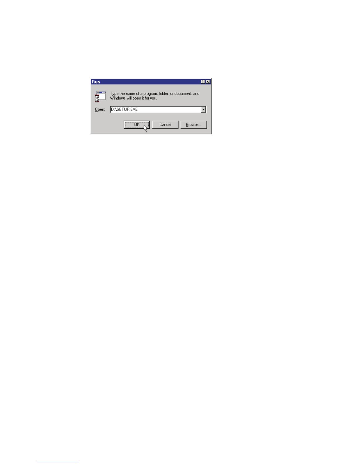
To install AutoSketch if you have turned off Autorun
1 Insert the AutoSketch CD into your CD-ROM drive.
2 On the Windows start menu, click Run. The Run dialog box appears.
3 Enter D:\Setup.exe and click OK. If you are installing from a different
drive, substitute the correct drive in place of the letter D.
4 Follow the installation prompts that appear.
To run AutoSketch after installation is complete,
Programs, AutoSketch.
Registering AutoSketch
If you have Microsoft Internet Explorer installed on your system, Autodesk
Online Software Registration can be launched during installation.
Registering makes you eligible for technical support and for early notification
when new product releases become available. It also provides Autodesk with
important information about how you use your software.
About This Guide
You can use this guide both as a tool for learning AutoSketch and as a reference manual after you’re familiar with the software.
This guide is tailored to help you find information quickly. The beginning of
each paragraph signals the thought or point covered in the paragraph. To
find information on a specific subject you can usually scan through text
reading only the first few words of each paragraph until you find the information you want. Illustrations, screen shots, tables, icons, and so on replace
explanatory text where possible.
on the Start menu, click
6 | Chapter 1 Welcome
Page 17

“How-to” information appears in numbered steps. This simplifies the learning process for new users and helps experienced users find essential
information quickly.
Instructions for installing and using Windows NT 4.0, Windows 98,
Windows ME, Windows 2000, or Windows XP do not appear in this guide.
If you are uncomfortable with your knowledge of Windows, review
Windows NT 4.0, Windows 98, Windows ME, Windows 2000, or
Windows XP online Help before attempting any serious work with
AutoSketch.
Visual Cues
This guide uses certain symbols and typographical conventions to help you
find information quickly. They are listed here:
Typographical conventions
Convention Meaning
■
item in a list
1. step in a procedure
Bold denotes something you must type exactly as it appears
Italics signals a new term; an explanation usually follows
ALL CAPS key names
KEY+KEY key combination (e.g., CTRL+R)
KEY, KEY, KEY key sequence (e.g., ALT, F, S)
Initial Caps filenames and names of menus, dialog boxes, and dialog box
controls
About This Guide | 7
Page 18
Illustrations
This guide uses two types of illustrations. One depicts the AutoSketch screen
or some element onscreen. When this type of illustration is necessary, every
effort is made to depict the element exactly as it appears on the actual
display.
The other type of illustration demonstrates an action or principle. Each
element in a drawing of this type has a specific meaning. Here is a list of the
conventions used in procedural illustrations:
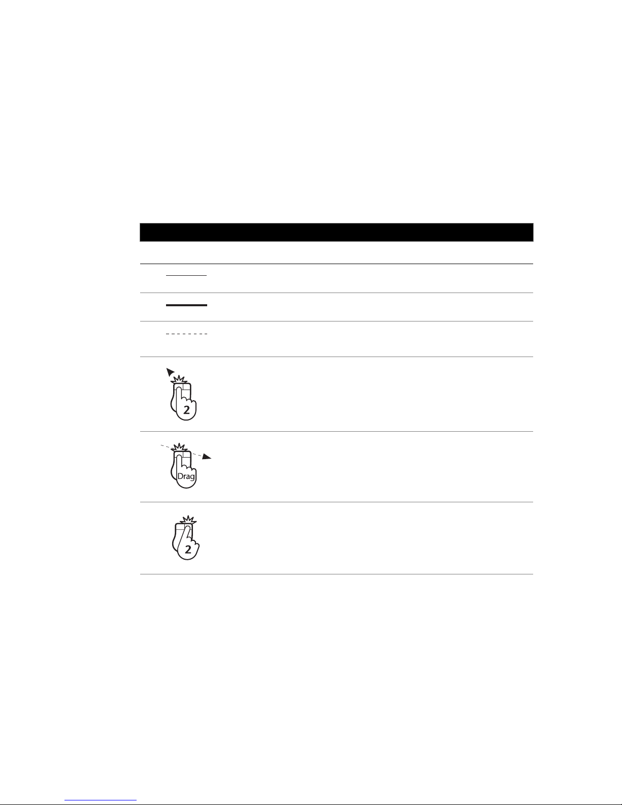
Elements used in procedural illustrations
Convention Meaning
existing entity
new entity
imaginary line (e.g., rubber band line or line used to show
alignment)
mouse click that selects an entity or a point—the number, when
present, specifies the mouse click’s position in a series of clicks
click and drag operation—beginning of arrow indicates where to
start; end of arrow indicates where to stop
last mouse click in a procedure that requires termination (e.g.,
polyline, baseline dimension, etc.)
OR
mouse click that opens a pop-up menu—the number, when
present, specifies the mouse click’s position in a series of clicks
8 | Chapter 1 Welcome
Page 19

Online Help
AutoSketch includes an extensive online Help system. This system includes
all of the information found in the AutoSketch User’s Guide, plus information
not found in the guide. Advanced topics, such as information on tracing,
importing and exporting, and customizing AutoSketch, are found exclusively in online Help. For a complete list of topics which appear exclusively
in online Help, refer to the Appendix on page 357. To access the online Help
system, click AutoSketch Help on the Help menu, or press F1.
Online Help | 9
Page 20

10 | Chapter 1 Welcome
Page 21

Important Concepts
2
AutoSketch allows you to create drawings that are
attractive, precise, and information rich. The building
blocks of any AutoSketch drawing are its entities, whose
geometry and appearance are defined by properties. A
hallmark of AutoSketch is its ability to store drawing
information in a database. From the manufacturer of a
product, to the World Wide Web address of the
company where you can buy it, AutoSketch allows you
to create drawings that are greater than their appear-
ance. This chapter introduces you to the general
concepts of AutoSketch so that you can take full
In this chapter
■ Entities
■ Properties
■ Coordinates
■ Drawing origin
■ Scale
■ Layers
advantage of its power.
11
Page 22
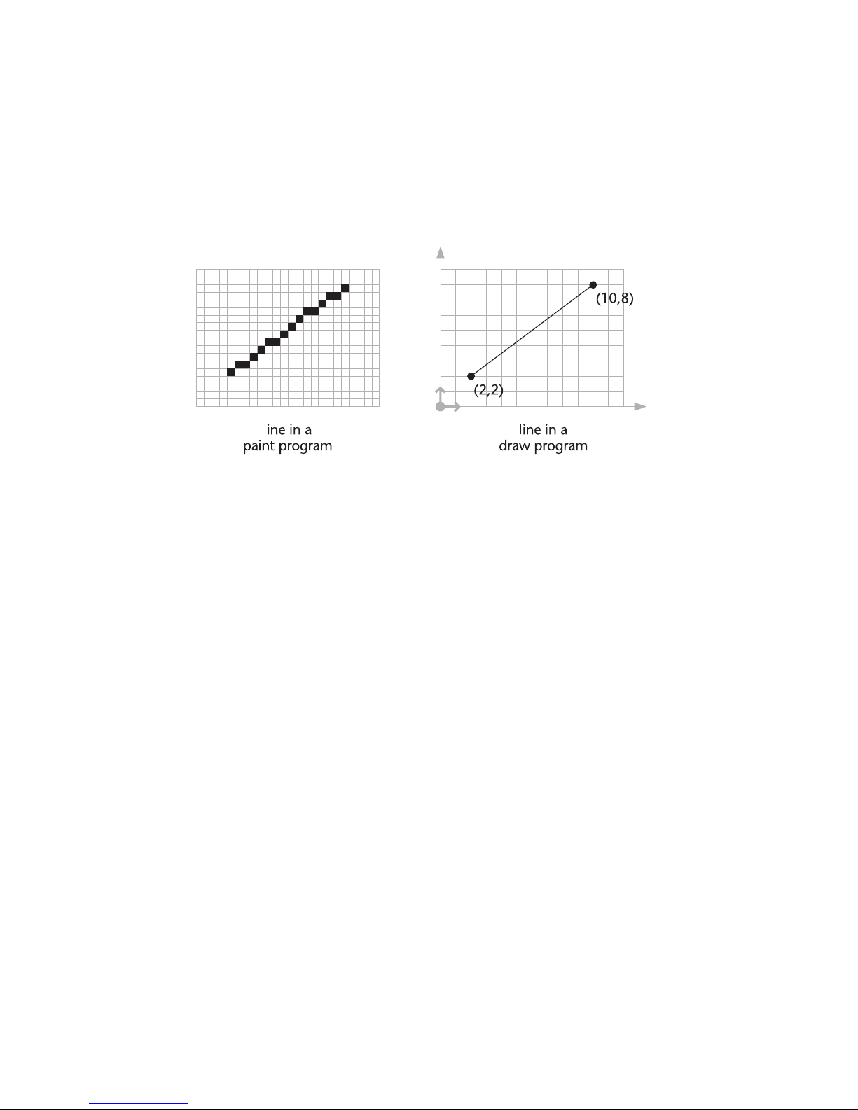
You are probably familiar with “paint” and “draw” programs that are common on personal computers. A paint program creates an image by assigning
colors to each dot in a rectangular array of dots. A draw program creates an
image by defining objects mathematically. A line, for example, is a specific
pattern of dots in a paint program. In a draw program, a line may have properties such as color, width, style, and so on, but in its simplest form, it has a
startpoint and an endpoint.
AutoSketch is similar to an ordinary draw program, but it goes a few steps
further. It allows you to work with the actual (world) sizes of the objects you
draw whether those objects are miles, millimeters, or microns across. It also
allows you to zoom in or out of your drawing almost without limit. And
during all of this, it keeps track of the scale of your drawing, showing you
exactly how it will appear when printed.
But there is more to a AutoSketch drawing than the way it looks. Underlying
each drawing is a database—a series of predefined and user-defined properties that you can use as a basis for selecting entities, generating reports, and
exporting information to other Windows applications. For example, by
assigning properties to a line, you can record the fact that it represents a halfinch cold water pipe located under the master bedroom. The ability to store
and recall database information makes AutoSketch a powerful tool for
organizing graphic and textual information.
In this brief chapter, you will learn about the special concepts on which
AutoSketch is based. Reading it helps you understand how AutoSketch works
and makes it easier for you to become productive.
12 | Chapter 2 Important Concepts
Page 23

Entities
Each item you add to a drawing is called an entity. Entities are the building
blocks of a drawing. Other programs may refer to entities as objects, items,
or elements. AutoSketch creates the following entity types:
■ Arc—An arc is a portion of a circle. You can use an arc to show the direc-
tion a door swings, a rounded wall, and so on. For more information, see
the chapter titled “Arcs & Circles,” which begins on page 155.
■ Circle—A circle is a curved line with every point equally distant from the
center. You can use a circle to represent a hole, a round object, and so on.
For more information, see the chapter titled “Arcs & Circles,” which
begins on page 155.
■ Curve—A curve is a polyline that is rendered onscreen and on printed
output in a special way. AutoSketch supports two curve types: fitted
curves and spline curves. Fitted curves pass directly through each control
point. Spline curves pass through the first and last control points and are
drawn toward intermediate ones. A closed curve can contain pattern fill.
Use curves to create free-form shapes such as curved sidewalks and car
fenders. For more information, see the chapter titled “Polylines, Polygons,
& Curves,” which begins on page 137.
■ Detail view—An entity that displays a portion of a previously saved view.
For more information, see “Viewing Drawing Details” on page 95.
■ Dimension—A dimension is a predefined collection of lines, arcs, markers,
and text used to display a measurement in the drawing. The text label is
updated automatically when you stretch or reshape the dimension. For
more information, see the chapter titled “Creating Dimensions,” which
begins on page 225.
■ Ellipse—A closed symmetrical curve that resembles a flattened circle.
Mathematically, the path of a point that moves so the sum of the dis-
tances from it to a pair of fixed points remains constant. For more infor-
mation, see “Drawing Ellipses” on page 163.
■ Fill—A hidden line polygon that conforms to the shape of a bounded area
and displays either a solid color, a hatch, or bitmap fill. For more informa-
tion, see the chapter titled “Pen & Pattern Properties,” which begins on
page 197.
■ Group—A compound entity consisting of individual symbols and entities
which AutoSketch treats as a single entity. For more information, see “Cre-
ating Groups” on page 319.
■ Line—A line is an entity that connects two points. You can use a line to
represent any straight object such as a water pipe, a wall edge, an electrical
connection, or a street. For more information, see the chapter titled
“Lines,” which begins on page 129.
Entities | 13
Page 24

■ Marker—A marker is a special entity that notes a specific point in a draw-
ing. For more information, see the chapter titled “Markers,” which begins
on page 241.
■ OLE Object—An OLE object is a special entity created in one application
and embedded into another. When you double-click a linked OLE object,
Windows opens the source application that created it and loads the associated file. When you double-click an embedded OLE object, the source
application opens within AutoSketch—that is, its toolbars, menus, and so
on, temporarily replace AutoSketch’s. For more information, see “Using
the Clipboard &OLE” in online Help.
■ Picture—A raster image is a picture or bitmap that can be imported and
placed in the drawing. AutoSketch treats the raster image like most other
entities, allowing you to move, scale, or duplicate it as needed. For more
information, see “Tracing in AutoSketch” in online Help.
■ Polygon— A polygon is a closed polyline that can contain a fill pattern.
Use a polygon when you need to know the area of an enclosed region or
when you need to fill an area with a hatch pattern, bitmap fill, or a solid
color. For more information, see the chapter titled “Polylines, Polygons, &
Curves,” which begins on page 137.
■ Polyline—A polyline is a multi-segmented line AutoSketch treats as a
single entity. When a polyline is closed, it becomes a polygon. Use a
polyline in situations where you need to know the total length of a series
of connected segments.
■ Symbol—A symbol is a group of entities that AutoSketch treats as a single
entity. Symbols can be stored in libraries for use in multiple drawings. For
more information, see the chapter titled “Symbols,” which begins on page
167.
■ Text—A text entity can be any size and can use any TrueType font. It can
be rotated at any angle. For more information, see the chapter titled
“Working With Text,” which begins on page 211.
14 | Chapter 2 Important Concepts
Page 25

Properties
Properties, the individual qualities that define an entity, are divided into
three categories:
■ Geometric properties—those that define an entity’s size, position, and so
on. AutoSketch assigns geometric properties automatically as you draw
and edit.
■ Graphic properties—those that specify the appearance of an entity.
Graphic properties include layer, color, width, style, and pattern.
AutoSketch assigns graphic properties as you draw based on the current
settings on the property bar.
■ Fields—those you define yourself. You define a field by specifying its
name, type, and width or precision. A desk symbol, for example, could
have fields for model, size, color, and style. A resistor symbol for a printed
circuit board could have fields for resistance, wattage, and tolerance. You
can assign fields to any entity except a text entity, a marker, or a dimen-
sion. A field has two components: a field name, such as Manufacturer,
and a value, such as “AAA Casements.” Assigning this value to the
Manufacturer field of a window symbol attaches that information to the
symbol.
Coordinates
Coordinates are numbers that specify the location of one point in relation to
another. This relationship is classified as either absolute or relative. Absolute
coordinates reference the origin of the current coordinate system, for example, the Drawing Origin, the Grid Origin, or the Page Origin. Relative coordinates reference the last point you entered. They are useful when you want to
draw or place another entity a known distance from another entity or point.
Properties | 15
Page 26
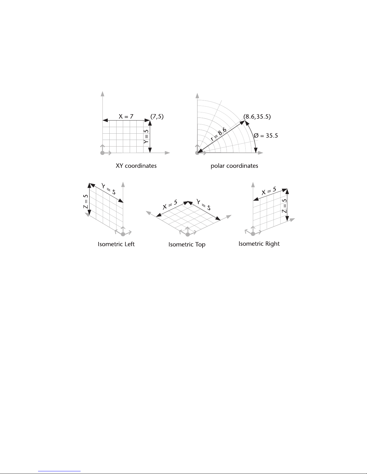
AutoSketch expresses location in three ways: xy (Cartesian), polar, and
isometric coordinates. X-and y-coordinates express location in terms of hori-
zontal and vertical distances from another point. Polar coordinates express
location in terms of distance (radius) and angle. For example, the xy coordinates 7,5 are equivalent to the polar coordinates 8.6,35.5.
Isometric coordinates differ from x- or y-coordinates in that they add a third
axis (z) to the expression. Isometric drawings are usually used to create twodimensional views of a three-dimensional object.
Drawing Origin
AutoSketch locates most points in relation to the drawing origin, even if you
move the grid origin. If you move the drawing origin on the page, the entire
drawing shifts to reflect that change. The drawing origin appears onscreen as
colored arrows indicating the positive x and y (and, if isometric, z) directions.
It does not appear on printed output. Normally, the drawing origin is located
at the lower-left corner of your page, however, if you need to move it, you
can center the Drawing Origin on the page, or relocate it with the mouse, or
by entering new coordinates. For more information on moving or modifying
the Drawing Origin, see “Moving the Drawing Origin” on page 49.
16 | Chapter 2 Important Concepts
Page 27

Grid Origin
The grid origin is similar to the drawing origin in function and appearance.
However, the grid origin serves as a reference point for grid coordinates only.
By default the grid origin is located at the drawing coordinates 0,0, for
example, at the drawing origin. You can move the grid origin of rectangular,
circular, or isometric reference grids. For more information, see the chapter
titled “Customizing the Grid,” which begins on page 59.
Drawing Scale
Drawing scale is the ratio between the actual size of the entities in a drawing
and their size on printed output. In conventional drafting, you scale the
components of a drawing by using an architectural or engineering scale. In
AutoSketch, you simply enter the actual (world) size of an entity and the software keeps track of the scale for you. You can also create “scaleless” 1:1 drawings in AutoSketch without regard for scale.
Specifying a drawing scale, however, has two important benefits. It allows
AutoSketch to accurately depict onscreen how your drawing will look on a
printed page. And it allows you to specify entities such as text, markers, and
dimensions by output size. This is usually more convenient than specifying
such entities according to their size in relation to actual (world) entities. For
information on how to change the drawing scale, see “Setting the Drawing
Scale” on page 47.
Layers
Layers help you place entities together in logical groups. An architectural
floor plan, for example, might contain a framing layer, a plumbing layer, an
electrical layer, and so on. You can mask layers while working on others to
remove distracting clutter and improve performance. Masked layers are not
printed or displayed. You can also lock a layer to protect its contents from
unintended change. For information on layers, see “Organizing With Layers”
in online Help.
Grid Origin | 17
Page 28

18 | Chapter 2 Important Concepts
Page 29

Screen Layout
3
The AutoSketch screen provides an assortment of
features that make it easy to create precise technical
drawings. This chapter describes the components of the
AutoSketch screen.
In most cases, this chapter does not provide detailed
information on standard Windows concepts or on
specific menu items. For information on standard
Windows concepts, such as the mouse, the Control
menu, the window border, the maximize button, dialog
box controls, and so on, refer to Windows online Help.
In this chapter
■ Title bar
■ Menu bar
■ Drawing windows
■ Drawing and grid origin
■ Toolbars
■ Property bar
■ Edit bar
■ Status bar
■ Content Librarian
■ Pop-up menus
■ ToolTips and pop-up
windows
19
Page 30
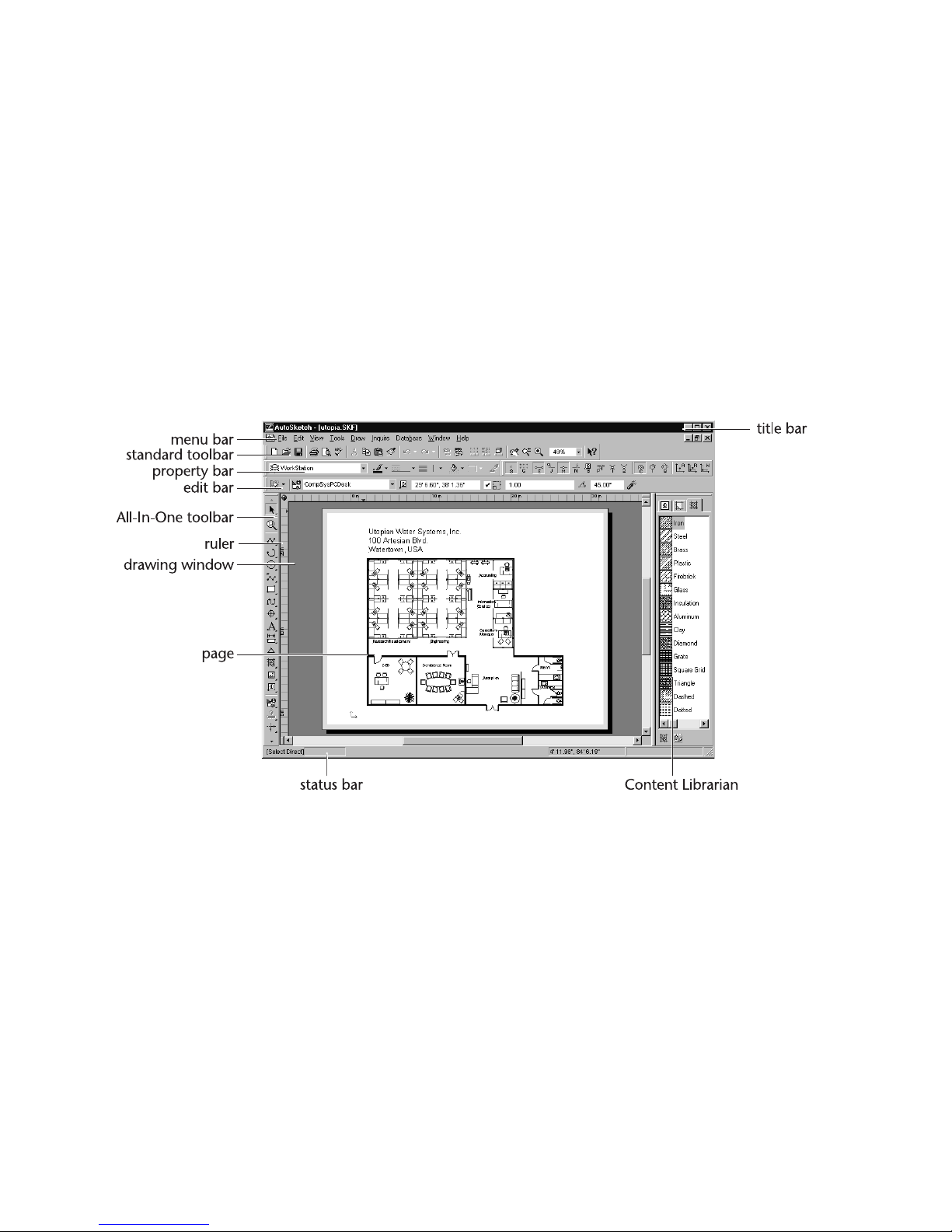
Title Bar
The AutoSketch title bar extends across the top of the application window. It
displays the name of the program and the name of the current drawing file
if the window that contains the drawing is maximized. The buttons at the
right end of the title bar allow you to minimize, maximize, close, or restore
the AutoSketch window. You can also maximize or restore a window by
double-clicking on the title bar. You can exit AutoSketch
Control menu box, then clicking close on the drop-down menu. Doubleclicking the Control menu box at the left end of the title bar is another quick
way to exit. If AutoSketch is running in a window rather than maximized,
dragging the title bar moves the entire window on the desktop.
by clicking the
Menu Bar
You can choose menu items using either the mouse or the keyboard. To use
the mouse, click the menu name. When the menu drops down, click the item
you want. Menu items with an arrow to the right display cascading menus
when you place the pointer over one of them. When you highlight a menu
item a description appears in the status bar.
20 | Chapter 3 Screen Layout
Page 31

To use the keyboard, press ALT and type the underlined letter in the menu
name, then the underlined letter in the menu item’s name. If there is a
cascading menu, you must type another letter. You can also use arrow keys
to move through menu items, and press ENTER to select one. Pressing ESC
backs out of the menu items one level at a time.
There are single-key or key combination shortcuts for certain frequently-used
menu items. Each menu lists available shortcut keys to the right of the item’s
name.
You can use the techniques for choosing menu items in combination. For
instance, you could press ALT+D to choose Draw, then use the down arrow
to choose Line, then use the mouse to click Single.
Drawing Windows
The large area in the center of the AutoSketch screen is the workspace. This
area contains drawing windows for each open drawing. The amount of
memory in your computer limits the number of open drawings.
The title bar of each drawing window displays the name of the drawing it
contains. When a drawing window contains a new, unsaved drawing, the
title bar displays the word Drawing followed by a number that reflects the
number of new drawings created in the current AutoSketch session.
Drawing Windows | 21
Page 32

The active window contains the drawing on which you are currently working
and is the only one in which you can make changes. Normally, the title bar
of the active window is displayed in a color different from those of other
windows. Clicking a drawing window makes it active. You can resize,
minimize, maximize, and close each drawing window independently.
Page
The large rectangle that appears in the drawing window when you load a
drawing is the page. The shaded bands along each edge of the page are the
margins. You can draw in the margins and off of the page, but any part of a
drawing that falls in this area does not normally appear on scaled output.
AutoSketch reads the default margins from the default Windows printer
driver. For more information, see “Setting the Page Size” on page 51 or “Setting the Margins” on page 54.
The pattern of lines, crosses, or dots on the page is called the reference grid. It
has three components:
■ Snap grid
■ Major grid
■ Minor grid
The snap grid is invisible. It is the grid to which points “snap” when you use
Gridpoint snap. The major and minor grids are comprised of lines, crosses,
or dots, and appear onscreen for reference only. They do not appear on
printed output. You can also create guidelines whose purpose is similar to the
reference grid. Guidelines are lines (which extend infinitely) or circles to
which you can snap points to help you draw. For more information, see the
chapter titled “Customizing the Grid,” which begins on page 59.
When you create a new drawing using the Standard Blank Drawing template,
AutoSketch automatically assigns a page size and orientation based on the
default printer. If you prefer a different size or orientation, you can redefine
the page using Page Setup on the File menu. If you choose a page size that is
larger than the paper for which your printer is configured, AutoSketch automatically tiles the drawing.
Tiling is the process of printing a drawing on multiple sheets of paper. Several
factors affect tiling, including page size, page orientation, and margin settings. You can display the tiling pattern onscreen by checking the Page Tiling
check box on the Appearance page of the View Options dialog box.
22 | Chapter 3 Screen Layout
Page 33

Scroll Bars
Scroll bars allow you to move across the drawing—that is, to change the part
of the drawing visible in the window without changing the level of
magnification.
■ To move the view in small increments, click the scroll arrow that points
in the direction you want to move.
■ To move in larger increments, click the control shaft, between the scroll
box and a scroll arrow.
■ To move by a custom increment, drag the scroll box in the direction you
want to move.
■ To hide the scroll bars from view, uncheck the Scroll Bars check box on the
Appearance page of the View Options dialog box.
Rulers
Rulers appear along the top and left sides of the drawing window. They represent units of measurement either in world size (the actual size of the object
you are drawing), or the current page (output) size, depending on which ruler
is active.
■ To switch between rulers, click the toggle button in the upper left corner
of the drawing window.
■ To hide rulers from view, uncheck the Rulers check box on the Appearance
page of the View Options dialog box.
For more information on using Rulers in AutoSketch, see “Using Rulers” on
page 53.
Split Boxes
Split boxes allow you to split a drawing window into two or four panes—areas
that display separately controllable views of a drawing. There are several ways
to split and unsplit a window.
■ To split a window at a specific location, drag the appropriate split box to
that location.
■ To split a window at the exact center, double-click the horizontal or verti-
cal split box. On the Control menu, click Split to split a window into four
equal panes.
■ To unsplit a window, drag the appropriate split bar to a corner, double-
click the split bar, or on the Control menu, click Unsplit.
Drawing Windows | 23
Page 34
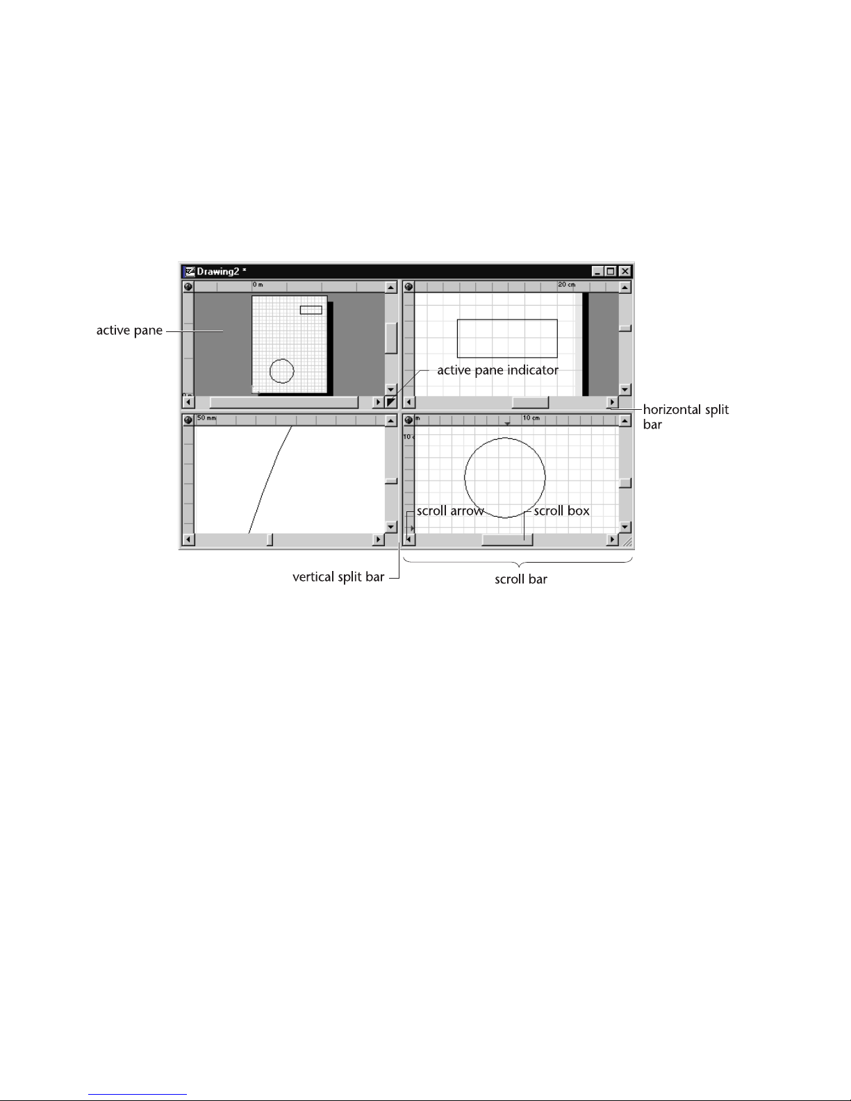
Some tools, such as Redraw and Extent, affect only the “active” pane. When
there is only one pane, it is always active. When the drawing window is split
into multiple panes, the active pane is the one to which the active pane indicator points.
■ To change the active pane, click the active pane indicator until it points
to the correct pane. You can also change the active pane by pressing F6 or
SHIFT+F6.
Drawing and Grid Origin
By default, the drawing and grid origins are located in the lower left corner
of the drawing page. AutoSketch measures all points in relation to the drawing origin. You can easily change the location of the origin, but if you move
the origin, all entities in the drawing move with it.
■ To hide the origin from view, uncheck the Drawing Origin check box on
the Appearance page of the View Options dialog box.
■ To change the drawing origin colors, click the axis (direction) you want to
change on the Appearance page of the View Options dialog box. The
Color dialog box appears. Simply adjust the Red, Green, and Blue color
values (RGB values) and click OK.
24 | Chapter 3 Screen Layout
Page 35

Toolbars
Clicking a button on a toolbar has the same effect as choosing the menu item
or operating mode it represents.
A toolbar often contains more buttons than are practical to display at once.
Because of this, buttons are divided into toolsets. Each toolset contains a
group of buttons that represent similar functions. For instance, all of the
polyline tools are located in one toolset. Only one button from a toolset is
visible at a time—normally, the one used most recently. Even when you
initiate an action or mode by other means, the corresponding button, if it is
present in a toolbar, is made the current one in its toolset. For example, if you
type the letter X to switch to the X-axis lock modifier, the Lock Modifier
toolset in the All-In-One toolbar is updated to reflect the change. Buttons
that contain hidden toolsets contain a small arrow in the lower right corner.
To select a button that is not visible, click the top button and hold for a
moment. When the complete toolset appears, drag the pointer to the button
you want and release.
The Standard toolbar contains buttons that perform some of the most common tasks in AutoSketch, such as opening, copying, and printing files, and
so on. Buttons on the left side of the Standard toolbar are exactly the same
as other toolbars in Microsoft Office 97-compatible products. The Standard
toolbar also contains the context-sensitive Help button, which you can use
to display pop-up window Help on buttons or anything else in the
AutoSketch application window.
You can move a toolbar to almost any location in the AutoSketch window by
clicking near its left edge then dragging it to its new location. Toolbars can
also be docked alongside one another. To dock a toolbar, simply click and
drag the toolbar alongside another toolbar.
The All-In-One, Standard, and other built-in toolbars (such as the Snap toolbar which contains tools for activating snaps) are predefined and cannot be
changed. You can create other toolbars, however, and configure them as you
like. In a custom toolbar you can specify which buttons to include, how the
buttons are grouped, and the name of the toolbar. For every toolbar you can
specify location and whether to hide or display it. You can change the button
size used in all toolbars. For information on how to customize a toolbar, see
“Creating Custom Toolbars” in online Help.
Toolbars | 25
Page 36

In all, there are 31 predefined toolbars in AutoSketch. Most consist of tools
that are also available as toolsets on the All-In-One toolbar. Others, such as
the Grid toolbar, contain unique commands that are useful to specific
situations. The visibility of all toolbars can be controlled from the Toolbars
dialog box by checking or unchecking the toolbars. If a check appears in the
check box next to a toolbar’s name, that toolbar is visible onscreen.
Property Bar
The property bar is the primary means by which you specify the current
layer, color, style, width, and pattern. Any change you make on the property
bar affects future entities and any entities that are currently selected.
■ To change a setting on the property bar, click the drop-down list and make
a new selection.
■ To apply a new setting to an entity, select the entity you want to change,
then click the current property setting on the property bar.
If you forget the meaning of an item on the property bar or in a drop-down
list, hold the pointer over it for a moment and a ToolTip and status bar
message appears.
The Pattern control is somewhat different from other controls on the property bar. It applies only to polygons and closed curves. The Pattern control
has three settings:
■ None specifies no pattern fill.
■ Solid color specifies a solid fill pattern.
■ Hatch specifies a hatched fill pattern or bitmap image.
The drop-down list box next to the Pattern control lists all the Solid, Hatch
patterns, and bitmap images available. For Solid patterns, the control allows
you to select one of 256 named colors. For Hatch patterns, it allows you to
select one of several standard patterns or bitmap images. You can also create
your own hatch patterns and bitmap images. For more information, see
online Help.
TIP A quick way to display the Graphic Options or Layer Properties dialog
boxes is to right-click the corresponding control on the property bar, then click
Layer Properties or Graphic Options on the pop-up menu that appears.
26 | Chapter 3 Screen Layout
Page 37

You can change the location of the property bar by clicking and dragging it.
The property bar can also be docked alongside another toolbar. To dock the
property bar, simply click the left edge of the bar and drag it alongside
another toolbar.
You can specify whether the property bar is hidden or displayed by rightclicking any bar, and clicking Property on the pop-up menu. If Property is
checked, it is displayed. If it is unchecked, it is hidden from view. The same
is true for all bars listed on the pop-up menu.
Edit Bar
The controls on the edit bar allow you to edit the geometric properties of
most entities. The controls change depending on your current activity, selection set, grid, and so on. When you select a single entity or when you draw
an entity, the edit bar displays controls based on the entity type. When you
click buttons for Transform and Trim operations, the edit bar displays corresponding controls.
edit bar
pointer
The various text boxes on the edit bar display information such as coordinates, angles, line widths, bulge factors and other information appropriate to
the entity that is selected. You can change any of these values by clicking in
the appropriate text box to place an insertion point, then entering the new
value on the keyboard, and pressing ENTER. If you want to change more than
one value, use TAB to move the insertion point to the next text box to the
right.
You can change the location of the edit bar by clicking on its left edge and
dragging it. The edit bar can also be docked alongside another bar by simply
dragging it there, though the edit bar may not fully appear if space is limited.
You can specify whether the edit bar is hidden or displayed by right-clicking
any bar, and clicking Edit on the pop-up menu. If Edit is checked, it is displayed. If it is hidden, some commands will not work. The same is true for all
bars listed on the pop-up menu or in the Toolbars dialog box.
When the pointer changes to an Edit Bar pointer, AutoSketch requires you to
enter information on the edit bar. For instance, when you click the Edit Grid
button on the Standard toolbar, the grid edit controls appear and the pointer
changes to an Edit Bar pointer. All actions performed in this mode must be
performed on the edit bar.
Edit Bar | 27
Page 38

Status Bar
The status bar has two principal components: the message area and the dial.
The message area occupies the left end of the status bar and displays prompts
and other messages. The message area provides step-by-step instructions
during most procedures.
You can specify the information displayed in the message area by rightclicking the status bar then clicking Properties on the pop-up menu that
appears.
The dial occupies the right end of the status bar. The coordinates on the left
display the absolute location of the point (its position in relation to the drawing origin) and the coordinates on the right display the relative location of
the point (its position in relation to the last point entered). You can specify
whether AutoSketch displays coordinates as XY, polar, or isometric
coordinates.
To change the type of coordinates displayed, right-click the status bar, then
click Properties on the pop-up menu. Click the Coordinate Display page tab,
then click one of the Coordinate System buttons. If you want AutoSketch to
automatically switch between coordinate systems, check the Automatically
28 | Chapter 3 Screen Layout
Page 39
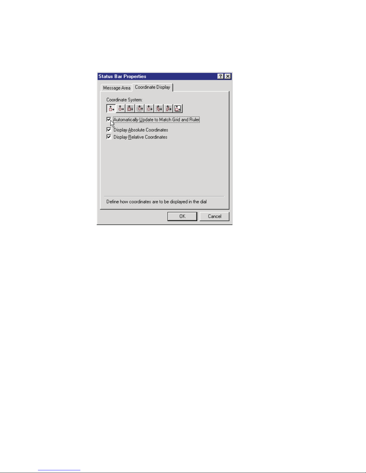
Update to Match Grid and Ruler check box. You can also select whether
absolute or relative coordinates are displayed by checking their corresponding check boxes.
You can specify whether the status bar is hidden or displayed by rightclicking any bar, and clicking Status on the pop-up menu. If Status is
checked, it is displayed. If it is unchecked, it is hidden from view. The same
is true for all bars listed on the pop-up menu.
Status Bar | 29
Page 40
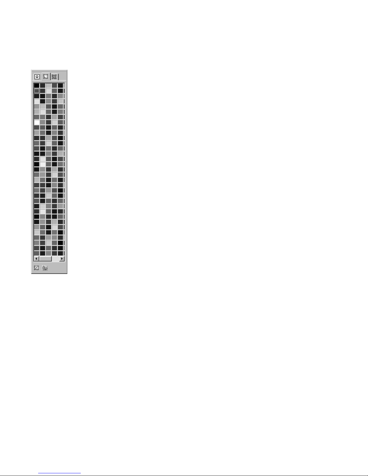
Content Librarian
The Content Librarian is an easy-to-use bar for displaying and placing
symbols, solid colors, hatch patterns, and bitmap fills. When you start
AutoSketch, the Content Librarian is visible on the right side of the application window. It consists of three tabbed pages and a display window.
Depending on which page is displayed, the Content Librarian may also have
additional tools displayed along the bottom.
When you click one of the three tabbed pages, the appropriate content
appears in the display window. You can then drag-and-drop content from the
Content Librarian to your drawing.
The Content Librarian allows you to place symbols in your drawing several
different ways. At the bottom of the Content Librarian, click the appropriate
tool for placing symbols by their basepoint, inserting them in lines, or
creating arrays.
The Content Librarian also allows you to fill a bounded area with a solid
color, hatch, or bitmap fill. Simply click the solid color, hatch, or bitmap fill
on the Content Librarian, drag it into the drawing, and drop it in an area that
is bounded on all sides. AutoSketch creates a special hidden-line polygon
that automatically conforms to the shape of the area. This polygon displays
the fill property you selected on the Content Librarian.
You can move the Content Librarian to almost any location in the
AutoSketch window by clicking near its top edge then dragging it to its new
location.
The visibility of the Content Librarian can be controlled from the Toolbars
dialog box. If a check appears in the check box next to Content Librarian, it
is visible onscreen.
30 | Chapter 3 Screen Layout
Page 41

Pop-up Menus
Pop-up menus provide quick access to tools applicable to a specific situation
or task. They appear beside the pointer when you right-click specific parts of
the screen. These menus are context sensitive—that is, they contain choices
that are applicable in the context of your current situation. A pop-up menu
is available when the pointer is over:
■ The property bar, edit bar, or status bar
■ A toolbar
■ Any entity
■ The selection set
■ The about point
ToolTips and Pop-up Windows
ToolTips provide brief information about the name or nature of toolbar
buttons and controls. AutoSketch displays a ToolTip next to a button if you
place the pointer over the button and pause a moment. Additional information is shown on the status bar. You can hide ToolTips from view by unchecking the Show ToolTips check box in the Toolbars dialog box. To display the
Toolbars dialog box, click Toolbars on the View menu.
A pop-up window is a form of online Help that appears when you click the
What’s This? Help button on the Standard toolbar, then click a button,
control, or an area of a dialog box for which you need an explanation. The
pop-up window displays a sentence or short paragraph describing the item
clicked.
Pop-up Menus | 31
Page 42

32 | Chapter 3 Screen Layout
Page 43

Part 2
Managing Drawing Files
Chapter 4 Opening & Saving Drawings
Chapter 5 Setting Up a New Drawing
Chapter 6 Customizing the Grid
Chapter 7 Printing & Plotting
Chapter 8 Controlling Views
Chapter 9 Entering & Modifying Points
Chapter 10 Entering Lengths & Angles
33
Page 44

34 |
Page 45

Opening &
Saving Drawings
4
A drawing file contains all the information necessary to
recreate a drawing. Before you can work on a drawing,
you must open it—that is, display it on your screen.
Once the drawing file is open, you can modify, print,
save, and view it.
In this chapter
■ Opening a drawing file
■ Combining two drawings
■ Saving a drawing
■ Closing a drawing
■ Finding a Drawing
■ Accessing Autodesk
Point A
35
Page 46

You can have more than one drawing file open at a time. The exact number
of files that can be open depends on the amount of memory in your system
and the complexity of the drawing files. When you open a drawing file,
AutoSketch displays the drawing in a new window on top of any open
drawing windows.
To preserve a drawing file for later use, you must save it. If you have already
saved the drawing previously, you can save any changes using the Save
command on the File menu. You can save a new drawing, save the drawing
under a new name, or save the drawing using a different file type using the
Save As command.
Opening a Drawing File
Quickly open any of the last four or eight drawings you have worked on (you
specify four or eight in the Drawing Options dialog box) by clicking the file
names that appear at the bottom of the File menu. You can open any other
drawing, including drawings stored on Internet or FTP locations, using the
Open command on the File menu.
You can open a file as read-only to protect you from accidentally making
changes to an important drawing. If you check the Open as Read-Only check
box and then try to save changes, AutoSketch displays a message that the file
is read-only. If you need to modify the original, open it without using the
read-only feature.
To open a recently opened, saved, or closed drawing
■ On the File menu, click the name of the drawing you want to open. The
last few files you opened are listed near the bottom of the File menu.
To open an existing drawing
1 On the File menu, click Open, or click the Open File button on the
Standard toolbar. The Open Drawing File dialog box appears.
2 Navigate to the folder where the drawing is located using one of the
following methods:
■ Choose the drive and folder using standard Windows navigation
procedures.
■ Choose a location from the Places List on the left side of the dialog box
to navigate directly to the My Documents folder (or the Personal folder,
depending on which operating system you are using), the Desktop, or
the Favorites folder.
36 | Chapter 4 Opening & Saving Drawings
Page 47
3 Click the name of the drawing you want to open in the Filename list box,
or enter the name of the drawing in the Filename text box.
4 (optional) If you want to open a file of a different type, click a new file type
from the Files of Type drop-down list box. For more information, see the
Importing and Exporting topic in online Help.
5 (optional) To see a preview of the drawing, select the Display Preview
checkbox.
6 Click Open.
To open a drawing as read-only
1 On the File menu, click Open, or click the Open File button on the
Standard toolbar. The Open Drawing File dialog box appears.
2 Navigate to the folder where the drawing is located using one of the
following methods:
■ Choose the drive and folder using standard Windows navigation
procedures.
■ Choose a location from the Places List on the left side of the dialog box
to navigate directly to the My Documents folder (or the Personal folder,
depending on which operating system you are using), the Desktop, or
the Favorites folder.
3 Click the name of the drawing you want to open in the Filename list box,
or enter the name of the drawing in the Filename text box.
4 (optional) If you want to open a file of a different type, click a new file type
from the Files of Type drop-down list box. For more information, see
“Importing and Exporting” in online Help.
5 (optional) To see a preview of the drawing, select the Display Preview
checkbox.
6 Click the Open drop-down arrow, then select Open Read-Only.
To open a drawing from the Internet
1 On the File menu, click Open, or click the Open File button on the
Standard toolbar. The Open Drawing File dialog box appears.
2 Do one of the following:
■ Click the Search the Web icon at the top of the dialog box to navigate
the Internet using AutoCAD’s Browse the Web-Open dialog box.
■ Click the History icon in the Places List at the left of the dialog box to
navigate to the Internet locations from which you've recently downloaded or stored drawings.
Opening a Drawing File | 37
Page 48

3 If you selected Search the Web in step 2, enter the complete URL of the file
in the File Name text box.
NOTE Include the Transfer Protocol (i.e., http:// or ftp://) and the exten-
sion (i.e., .SKF or .DXF) of the file you want to open.
4 Click Open.
To open a drawing from an FTP site on the Internet
1 On the File menu, click Open, or click the Open File button on the
Standard toolbar. The Open Drawing File dialog box appears.
2 Click the FTP icon in the Places List.
3 On the Tools menu, click Add/Modify FTP Locations. The Add/Modify FTP
Locations dialog box appears.
4 In the Name of FTP Site text box, type the name of the FTP server.
5 In the Log on as section, choose either Anonymous or User.
6 If you select the User option, enter a user name in the combo box.
7 Enter a password in the Password text box.
8 Click Add.
9 Click OK to return to the Open Drawing File dialog box.
10 Navigate the FTP site using standard Windows navigation methods.
11 From the list of drawings, select the drawing you want to open.
12 Click Open.
Combining Two Drawings
You can add the contents of another drawing to the current drawing by
merging. If the drawing you want to merge was created in a program other
than AutoSketch, you must first import the drawing and save it in
AutoSketch (SKF) format. For information about importing drawing files, see
“Importing & Exporting” in online Help.
When you merge two files, AutoSketch ignores duplicated layer names, field
names, and symbol definitions. For example, if the current drawing and the
drawing you merge both have layers named “Walls,” but the settings for that
layer are not the same, AutoSketch uses the settings for the current drawing.
38 | Chapter 4 Opening & Saving Drawings
Page 49

To merge another drawing with the current drawing
1 On the File menu, click Merge. The Merge Drawing File dialog box
appears.
2 Click the name of the drawing you want to open in the Filename list box,
or enter the name of the drawing in the Filename text box. If you do not
see the name of the file you want, click a new drive, folder, or type of file.
3 Click Open. The Merge dialog box appears.
4 Enter the origin, scale, and rotation for the drawing being merged and
click OK.
Saving a Drawing
When you open a drawing, AutoSketch copies the drawing file to your computer’s memory. As you work, you are modifying the copy stored in memory.
To store your latest work on disk, you should save your work periodically. A
good rule of thumb is to save every 15 to 20 minutes, or after you’ve completed any work you wouldn’t want to redo.
TIP AutoSketch can automatically save your drawing periodically using the
Automatic Save feature. For information about how to enable Automatic Save,
see online Help.
Before you save a drawing for the first time, it is recommended that you
assign project information about your drawing. Project information is
descriptive text, such as the title of the drawing, your name, and the revision
number. Storing project information with your drawings can help you
remember important details about a drawing file later.
When you click the Save command, AutoSketch saves the active drawing
using the name and location you last gave it. Additionally, the Save As
command gives you the flexibility to:
■ Create more than one version of a drawing.
■ Save copies on another disk for safekeeping.
■ Save each version under a different name.
■ Save them under the same name in different folders or on different drives.
Saving a Drawing | 39
Page 50

The File page of the Drawing Options dialog box lets you specify whether
AutoSketch should create backup files when you save a file, whether it should
automatically save the current file at a time interval set by you, and whether
you want the File New dialog box or the Start Up dialog box to appear when
you click New on the File menu, or start AutoSketch. To reach these controls,
click Drawing Options on the Tools menu, then click the File page tab.
To save an existing drawing
■ On the File menu, click Save, or click the Save File button on the Standard
toolbar.
If you want to save changes to a read-only drawing, you must save the draw-
ing with a new name.
To save a new, unnamed drawing
1 On the File menu, click Save or Save As. The Save Drawing File dialog box
appears.
2 In the Filename text box, enter a filename. AutoSketch automatically adds
a SKF extension unless you specify another extension.
3 Click Save.
To save a drawing to a different name, format, drive, or folder
1 On the File menu, click Save As. The Save Drawing File dialog box appears.
2 If you want to save the drawing under another name, enter a new file-
name in the Filename text box.
3 If you want to save the drawing to a different drive or folder, click a differ-
ent drive and folder or enter the complete path in the Filename text box.
4 If you want to save the drawing in another format, click a new format in
the Files Of Type drop-down list box.
5 Click Save.
To enter project information for the current drawing
1 On the Tools menu, click Drawing Options. The Drawing Options dialog
box appears.
2 Click the File page tab.
3 Enter the appropriate text in text boxes in the Summary Information
section.
4 Click OK.
40 | Chapter 4 Opening & Saving Drawings
Page 51

Closing a Drawing
When you finish working with a drawing file, close it to remove the window
from the screen and to free up your computer’s memory. When you are done
working in AutoSketch, close all your drawing files and exit the program.
To close a file
■ On the File menu, click Close. If you have unsaved changes in your draw-
ing, you are prompted to save them before you close the file.
To close all open files
■ On the Window menu, click Close All. If any open drawings have unsaved
changes, you are prompted to save them before you close the files.
To close all open files and exit AutoSketch
■ On the File menu, click Exit. If any open drawings have unsaved changes,
you are prompted to save them before you close the files.
Finding a Drawing
AutoSketch’s Find tool allows you to search for a drawing based on it’s file
name, file type, or even its last-modified date.
To find a drawing
1 On the File menu, click Open, or click the Open File button on the
Standard toolbar. The Open Drawing File dialog box appears.
2 On the Tool menu, click Find.
3 On the Name & Location tab, specify a file type, file name, and path in
the appropriate text boxes. You can use wild cards when specifying a file
name.
4 On the Date Modified tab, choose All Files, or choose Find All Files Created
or Modified to specify a date filter. You can search for drawings modified
between a specified range of dates or within a specified number of months
or days.
5 Click Find Now.
6 Select one or more files from the search results and click OK.
Closing a Drawing | 41
Page 52

Accessing Autodesk Point A
Autodesk Point A’s design resources and services provide one-stop
productivity improvement for Autodesk customers. Clicking the Point A
button launches the Point A site in your Internet browser.
To access Autodesk Point A
■ Click the Point A button on the standard toolbar to launch Autodesk
Point A in your Internet browser.
42 | Chapter 4 Opening & Saving Drawings
Page 53

Setting Up
a New Drawing
5
Starting a new drawing is as easy as clicking a button.
AutoSketch offers many options that allow you to tailor
a drawing file to your needs. This chapter discusses most
of the options available when starting a new drawing.
For a discussion of grid options, see the chapter titled
“Customizing the Grid” on page 59.
In this chapter
■ The WIzards
■ Creating a new drawing
■ Selecting a template
■ Setting the drawing scale
■ Moving the drawing origin
■ Setting the page size
■ Using rulers
■ Setting the margins
■ Setting the units of
measure
43
Page 54

The Wizards
Since Wizards are, in general, self-explanatory, this book does not cover them
in detail. For a more complete discussion of Wizards, see online Help.
When you first begin AutoSketch, the Start Up dialog box appears. The
Wizard page lists several Wizards that direct you through various drawing
processes. Just click one of the following wizards and let it guide you through
the process of setting up the drawing:
■ Precise Drawing Wizard
■ Building Wizard
■ Office Layout Wizard
■ Workbench Wizard
■ Diagram Wizard
■ Mechanical Part Wizard
Creating a New Drawing
You can create a new drawing anytime you are working in AutoSketch. The
Start Up dialog box appears when you first begin AutoSketch and allows
you to:
■ Start new drawings
■ Select from a list of the most recently opened drawings
■ Load a template
You can also begin a new drawing after you have started a drawing session.
The New dialog box is a simpler form of the Start Up dialog box. Both list two
ways to begin a drawing:
■ Create New Drawing From Scratch allows you to begin drawing immediately
using AutoSketch’s default settings.
■ Create Precision Drawing allows you to configure AutoSketch for the
specific object you plan to draw by establishing an appropriate scale,
setting the page size and orientation, setting up the reference grid, specifying the units of measurement to be used, and so on.
Until you save the drawing, the name “Drawing” and a unique number
appear in the drawing window’s title bar. This name is replaced with the
drawing name you designate when you save it.
44 | Chapter 5 Setting Up a New Drawing
Page 55

To create a new drawing from start up using default settings
■ In the Start Up dialog box, click Create New Drawing From Scratch, then
click OK. The AutoSketch application window appears using the default
template and settings.
To create a new drawing from start up using custom settings
1 On the Start Up dialog box, click Create Precision Drawing, then click OK.
The AutoSketch application window and the New Drawing Wizard appear.
2 The New Drawing Wizard presents a series of dialog boxes that walk you
through the process of setting up your drawing.
To create a new drawing using default settings
■ Click the New button on the Standard toolbar.
OR
1 On the File menu, click New. The New dialog box appears.
2 Click Create New Drawing From Scratch, then click OK.
To create a new drawing using custom settings
1 On the File menu, click New. The New dialog box appears.
2 Click Create Precision Drawing, then click OK.
3 The New Drawing File Wizard presents a series of dialog boxes that walk
you through the process of setting up your drawing.
If you don’t want the Start Up dialog box or the New dialog box to appear,
they can be turned off using controls in the Drawing Options dialog box.
When the Start Up dialog box or the New dialog box is disabled, AutoSketch
opens each new drawing session as if you had selected Create New Drawing
From Scratch from the Start Up dialog box.
To disable the Start Up dialog box
1 On the Tools menu, click Drawing Options. The Drawing Options dialog
box appears.
2 Click the File page tab, then uncheck the Show Start Up Dialog check box.
When this box is checked, the Start Up dialog box appears when you
begin AutoSketch.
Creating a New Drawing | 45
Page 56

To disable the New dialog box
1 On the Tools menu, click Drawing Options. The Drawing Options dialog
box appears.
2 Click the File page tab, then uncheck the Show File New Dialog check box.
When this box is checked, the New dialog box appears when you click
New on the File menu.
Selecting a Template
AutoSketch includes dozens of drawing templates that make setting up draw-
ings a snap. Each template contains setup information such as the drawing
scale and page size, plus custom drawing features like borders. You can also
create your own template from an existing drawing and add it to the list of
templates available on the Template page of the Start Up or New dialog
boxes.
To select a template
1 In the Start Up dialog box click the Template page tab.
2 Click a new template from the Template list box. Notice that a preview of
the template style appears in the Preview window.
3 (optional) Check the Use Selection as New Default check box. When this
option is checked, your selection becomes the new default template.
4 Click OK.
OR
1 Click New on the File menu, then click the Template page tab in the New
dialog box.
2 Click a new template from the Template list box. Notice that a preview of
the template style appears in the Preview window.
3 (optional) Check the Use Selection as New Default check box. When this
option is checked, your selection becomes the new default template.
4 Click OK.
To delete a template
1 Click the Template page tab in the Start Up or New dialog boxes as
described in the preceding sets of steps.
2 Click the Organize Templates button. The Organize Templates dialog box
appears.
46 | Chapter 5 Setting Up a New Drawing
Page 57

3 Click the template you want to delete in the Templates list box, then
click Delete.
4 AutoSketch prompts you for a confirmation. Click Yes, then click Close.
To add a template
1 Click the Template page tab in the Start Up or New dialog boxes.
2 Click the Organize Templates button. The Organize Templates dialog box
appears.
3 Click Add. The Add Template From Drawing dialog box appears.
4 Enter the filename and the folder location to use as a template in the
Drawing Name text box. If you don’t know the filename or exact location,
click the Browse button, then select a drawing and click OK.
5 (optional) Check the Delete Existing Entities When Making Template
check box. When this option is checked, all entities in a drawing are
deleted from the template. Leave this check box unchecked if you want to
include entities such as title blocks in the new template.
6 Enter a new name for the template, then click OK. The Organize
Templates dialog box appears.
Setting the Drawing Scale
The drawing scale is the ratio of an object’s size on scaled output to its real
world size. AutoSketch lets you draw and measure using the real world size
of the items you are drawing. This allows you to enter lengths using real
world measurements. AutoSketch uses the drawing scale to resize your
printed drawing. For example, in a drawing whose scale is at one-quarter
inch equals one foot, a line that is one-quarter inch long when printed
represents a line that is actually one foot long.
You can change the drawing scale at any time. The controls are located on
the Scale page of the Drawing Options dialog box. You can choose from
many pre-set scales or enter a custom scale.
The Apply Scale Change check box applies any changes in scale to all text,
markers, and dimensions. These are specified in size on output, rather than
real world size. In all but rare cases, this option should be checked. All drawing parameters are updated, if this box is checked, by the ratio of the previous
scale to the new scale. If there are existing dimensions, text, or markers in
your drawing, click the Scale Annotation or Do Not Scale Annotation buttons
located to the left of the Apply Scale Change check box.
Setting the Drawing Scale | 47
Page 58

AutoSketch features two automatic scaling functions on the Scale page of the
Drawing Options dialog box that make setting your drawing scale easier.
AutoScale selects the closest scale from the current scale list. AutoFit calculates
a non-standard scaling factor that scales your drawing to the largest size that
will fit on the printed page. Using AutoFit may result in a scaling factor that
is not appropriate for most building, or other, standards.
To change the drawing scale to a common scale
1 On the Tools menu, click Drawing Options. The Drawing Options dialog
box appears.
2 Click the Scale page tab.
3 Click the page tab for Any Scale, Architectural, Engineering, Mapping, or
Metric.
4 Click a scale in the list box, then click OK.
To change the drawing scale to a custom scale
1 On the Tools menu, click Drawing Options. The Drawing Options dialog
box appears.
2 Click the Scale page tab.
3 Click the page tab for Any Scale, Architectural, Engineering, Mapping, or
Metric.
4 Click Custom Scale from the list box.
5 Enter the page units in the Page (Output) text box.
6 Enter the actual units in the Actual (World) text box. The ratio of the page
units to the actual units is the drawing scale.
7 Click OK.
To change the drawing scale and move an existing drawing so that it fits on
a single page
1 On the Tools menu, click Drawing Options. The Drawing Options dialog
box appears.
2 Click the Scale page tab.
3 Click AutoScale or AutoFit, then click OK. AutoScale selects the closest
scale from the current scale list. AutoFit calculates a non-standard scaling
factor that scales your drawing to the largest size that will fit on the page.
Using AutoFit may result in a scaling factor that is not appropriate for
most building, or other, standards.
48 | Chapter 5 Setting Up a New Drawing
Page 59

To create a custom scale
1 On the Tools menu, click Drawing Options. The Drawing Options dialog
box appears.
2 Click the Scale page tab, then click the Custom page tab.
3 Enter a value in the Page text box. This is the measurement used to repre-
sent real-world objects in your drawing.
4 Enter a value in the Actual text box. This is the real-world measurement
of the objects in your drawing.
5 Enter a name for your scale in the Name text box.
6 From the Drawing Origin drop-down list box, select a location for the
drawing origin. The default selection is Lower Left Corner.
7 (optional) If you select custom, enter x and y coordinates (these are
measured from the lower-left corner of the page) in the appropriate text
boxes.
8 (optional) Check the Display the Drawing Origin check box. When this
box is unchecked, the drawing origin is not displayed.
9 Click Add. The scale you created is added to the list of custom scales.
10 Click OK.
NOTE If you click Select After OK from the Drawing Origin drop-down list
box, you can use the mouse (and any snap) to place the drawing origin on
the page. Moving the drawing origin causes all entities in the drawing to
move the same distance and direction on the page.
Moving the Drawing Origin
When you create a new drawing, AutoSketch places the drawing origin at the
lower-left corner of the page. However, you can specify any point as the
drawing origin, either by entering coordinates or by entering a point with the
mouse. This is especially useful when you want to reposition the drawing on
the page without changing the coordinate values.
The drawing origin appears as colored arrows indicating the positive x- and
y-coordinate (and, if isometric, z-coordinate) directions. It does not appear
when you print your drawing.
You can also hide the drawing origin from view without affecting the origin’s
functionality.
Moving the Drawing Origin | 49
Page 60

To place the drawing origin at the lower-left hand corner or center of
the page
1 On the Tools menu, click Drawing Options. The Drawing Options dialog
box appears.
2 Click the Scale page tab.
3 Click Lower Left Corner or Center from the Drawing Origin drop-down
list box.
4 Click OK.
To reposition the drawing origin using coordinates
1 On the Tools menu, click Drawing Options. The Drawing Options dialog
box appears.
2 Click the Scale page tab.
3 Click Custom from the Drawing Origin drop-down list box.
4 Enter coordinates in the text boxes to specify the location of the drawing
origin on the page. These coordinates are measured in relation to the page
size from the lower-left corner of the page.
5 Click OK.
To reposition the drawing origin using the mouse
1 On the Tools menu, click Drawing Options. The Drawing Options dialog
box appears.
2 Click the Scale page tab.
3 Click Select After OK from the Drawing Origin drop-down list box.
4 Click OK.
5 Click a point on the page for the drawing origin.
To hide the drawing origin from view
1 On the Tools menu, click Drawing Options. The Drawing Options dialog
box appears.
2 Click the Scale page tab.
3 Uncheck the Display Drawing Origin check box. When checked, the
drawing origin is displayed, when unchecked, the drawing origin is
hidden from view.
4 Click OK.
50 | Chapter 5 Setting Up a New Drawing
Page 61

OR
1 On the View menu, click Options. The View Options dialog box appears.
2 Click the Appearance page tab.
3 Uncheck the Drawing Origin check box. When checked, the drawing
origin is displayed, when unchecked, the drawing origin is hidden from
view.
4 Click OK.
To change the colors of the drawing origin
1 On the View menu, click Options. The View Options dialog box appears.
2 Click the Appearance page tab, then click an Axis Color button in the
Screen section. The Color dialog box appears.
3 Click a color from the palette then click OK.
4 Click OK in each dialog box.
Setting the Page Size
You can set the page size by:
■ Using the page size of the current Windows printer
■ Specifying a standard size
■ Entering a tiling pattern based on the printer page
■ Entering custom measurements
When you create a new drawing, AutoSketch sets the page size using the size
of the current Windows printer. If you need to create a drawing larger than
the paper size your output device supports, AutoSketch will tile your printed
output on multiple printer pages. You can also specify the orientation of the
page.
To set the page size by using the page size of the current printer
1 On the File menu, click Page Setup. The Page Setup dialog box appears.
2 Click the Size page tab.
3 Click the Printer Page option button.
4 Click OK.
Setting the Page Size | 51
Page 62

To change the default printer page options
1 On the File menu, click Page Setup. The Page Setup dialog box appears.
2 Click the Printer Page page tab.
3 Click an item from the Paper Size drop-down list box. Notice that the
paper dimensions appear in the grayed boxes below the Paper Size dropdown list box.
4 Click an orientation from the Paper Orientation drop-down list box.
5 Click a source from the Paper Source drop-down list box.
6 Click OK.
To set the page to a standard size
1 On the File menu, click Page Setup. The Page Setup dialog box appears.
2 Click the Size page tab.
3 Click the Standard Size option button.
4 Click an item from the page size drop-down list box.
5 Click either portrait or landscape from the orientation drop-down list box.
6 Click OK.
To set the page size by tiling printer pages together
1 On the File menu, click Page Setup. The Page Setup dialog box appears.
2 Click the Size page tab.
3 Click the Tiling Pattern option button.
4 Enter the number of horizontal printer pages for the tiling pattern.
5 Enter the number of vertical printer pages for the tiling pattern, then
click OK.
To set the page size using exact measurements
1 On the File menu, click Page Setup. The Page Setup dialog box appears.
2 Click the Size page tab.
3 Click the Custom Size option button.
4 Enter the horizontal size of the page.
5 Enter the vertical size of the page, then click OK.
52 | Chapter 5 Setting Up a New Drawing
Page 63

Using Rulers
Rulers appear along the top and left sides of the drawing window. They represent units of measurement either in actual size, or the page size, depending
on which ruler is active.
Actual (world) rulers are based upon scale settings you choose and indicate
the actual size your drawing represents. For instance, the actual object in
your drawing might be 20’ x 60’. When you create a new drawing, the default
actual (world) scale setting is 1’’ =1’’. You can select a different scale setting
or create your own custom scale setting using the Drawing Options dialog
box. For more information on setting the scale, see “Setting the Drawing
Scale” on page 47.
Page (output) rulers reflect the size of the drawing page on output, and are
automatically updated to reflect printer or page size settings. For more information on setting the current page size, see “Setting the Page Size” on
page 51.
Alternating between page (output) rulers and actual (world) rulers is as
simple as clicking the mouse.
To alternate between actual (world) rulers and page (output) rulers
■ Click the actual or page icon in the upper-left corner of the drawing
window, where the top and left rulers intersect.
To change the actual (world) scale factor
1 On the Tools menu, click Drawing Options. The Drawing Options dialog
box appears.
2 Click the Scale page tab, then click the Any Scale page tab.
3 Click a scale from the list box.
4 (optional) Click a page tab for an alternate scaling method, then define a
scaling factor.
5 Click OK. The scaling factor you selected is applied to the current
drawing page.
To hide the rulers from view
1 On the View menu, click Options. The View Options dialog box appears.
2 Click the Appearance page tab.
3 Uncheck the Rulers check box on the Screen section. When checked, the
rulers are displayed in the drawing window.
Using Rulers | 53
Page 64
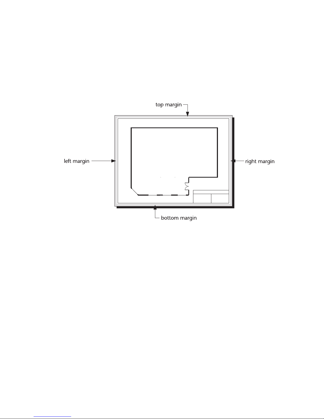
Setting the Margins
Most printers cannot print on the margin. AutoSketch indicates the margins
onscreen with a shaded band around the page. When you create a new draw-
ing, AutoSketch reads the hard margin from the current Windows printer
driver. You can specify a larger margin using the Page Setup dialog box, but
the hard margin is the minimum margin that your printer driver supports.
To adjust the margins
1 On the File menu, click Page Setup. The Page Setup dialog box appears.
2 Click the Margins page tab.
3 Enter the margin values in the appropriate text boxes.
4 Click OK.
Setting the Units of Measurement
You can set the default units of measurement using the Drawing Options
dialog box. The default units of measurement are the ones used by
AutoSketch to display measurements. AutoSketch also assumes the default
units of measurement if you do not specify a particular unit when entering
data. Regardless of the default units of measurement, you can always enter a
measurement using any of the units AutoSketch supports.
54 | Chapter 5 Setting Up a New Drawing
Page 65

Each type of measurement (e.g., linear, angular, etc.) has its own precision
settings. These settings control how AutoSketch formats numbers for output.
Regardless of these precision settings, AutoSketch always performs all
calculations at the maximum possible precision.
Setting the International Units of Measurement
AutoSketch lets you set the default measurement system for Windows from
within the program. You can set AutoSketch to use English or Metric units,
place leading zeros before decimal values, and format decimal numbers using
a comma instead of a period for the decimal separator.
To set the international units of measurement
1 On the Tools menu, click Drawing Options. The Drawing Options dialog
box appears.
2 Click the Units page tab.
3 Click a method from the Measurement System drop-down list box.
4 (optional) Check the Show Leading Zeros check box.
5 (optional) Click the Period or Comma option button in the Decimal
Symbol section.
6 Click OK.
Setting the Linear Units
AutoSketch allows you to choose from nine standard units of measurement
for lengths. Six are English measures and three are Metric. You can also
specify the precision AutoSketch uses to display decimal and fractional linear
values separately. The choices for decimal precision range from 1 to
0.0000001, while the choices for fractional precision range from 1 to 1/128.
To set the linear units of measurement
1 On the Tools menu, click Drawing Options. The Drawing Options dialog
box appears.
2 Click the Units page tab.
3 Select the units of measurement from the first drop-down list box in the
Length section.
4 (optional) To set the decimal precision for linear measurements, select a
value from the Decimal Precision drop-down list box.
5 (optional) To set the fractional precision for linear measurements, select a
fraction from the Fractional Precision drop-down list box.
6 Click OK.
Setting the Units of Measurement | 55
Page 66

Setting the Angular Units of Measurement
AutoSketch allows you to choose from six standard units of measurement for
angles: degrees, degrees-minutes-seconds, minutes, radians, bearing, and
grads. You can specify the precision AutoSketch uses to display angular
values from 1.0 to 0.0000001. You can specify whether AutoSketch measures
angles using the standard format or using compass orientation. For informa-
tion on compass angles, see “Compass Angles & Bearings” in online Help.
To set the angular units of measurement
1 On the Tools menu, click Drawing Options. The Drawing Options dialog
box appears.
2 Click the Units page tab.
3 Select the angular units of measurement from the first drop-down list box
in the Angle section.
4 (optional) Select a value from the Decimal Precision drop-down list box.
5 (optional) Select a method in the Orientation drop-down list box.
6 Click OK.
Setting the Area Units of Measurement
AutoSketch allows you to choose from eight standard units of measurement
for areas. Five are English measurements and three are metric. You can also
specify the precision AutoSketch uses to display area values. The choices for
decimal precision range from 1 to 0.0000001.
To set the area units of measurement
1 On the Tools menu, click Drawing Options. The Drawing Options dialog
box appears.
2 Click the Units page tab.
3 Click the units of measurement from the first drop-down list box in the
Area section.
4 (optional) Click a value from the Decimal Precision drop-down list box.
5 Click OK.
56 | Chapter 5 Setting Up a New Drawing
Page 67

Setting Decimal Precision for Scalar Values
AutoSketch allows you to set the decimal precision for scalar values. Scalar
values are unitless numbers, such as symbol scale or a bulge factor for a
polyline segment. The choices for decimal precision range from 1 to
0.0000001.
To set the decimal precision
1 On the Tools menu, click Drawing Options. The Drawing Options dialog
box appears.
2 Click the Units page tab.
3 Click a precision from the Precision drop-down list box in the Scalar
section.
4 Click OK.
Setting the Units of Measurement | 57
Page 68

58 | Chapter 5 Setting Up a New Drawing
Page 69

Customizing the Grid
6
Grids help you create precise drawings. The pattern of
lines, crosses, or dots which represent the grid visually is
an invaluable tool. Use the reference grid as a visual aid
for drawing, or increase the precision and uniformity of
the points you enter by using Gridpoint snap to
automatically snap points to the grid. This chapter
describes the three different types of reference grids
available in AutoSketch, and how you can use them to
your advantage.
In this chapter
■ Changing the grid
■ Using guidelines
■ Using the Grid edit bar
■ Using the Grid toolbar
59
Page 70

AutoSketch’s reference grid is an onscreen drawing aid consisting of a snap
grid and a pattern of lines, crosses, or dots which represent the grid visually.
You can use the reference grid as a visual aid for drawing, or you can increase
the precision and uniformity of the points you enter by using Gridpoint snap
to automatically snaps points you enter to the grid. There are three types of
reference grids available in AutoSketch, each suited for different purposes.
■ The default grid is rectangular, with snap intervals and lines that parallel
the x- and y-axes. This grid is the standard reference tool for most twodimensional drawings.
■ Circular grids extend radially from the grid origin. They provide an excel-
lent reference tool for drawings that require alignment of points along an
arc or circle, such as a mechanical drawing of a gear.
■ Isometric grids align along three major axes, instead of two. This allows
you to create two-dimensional drawings of three-dimensional objects.
Because perspective is not applied, the objects can be accurately
dimensioned.
AutoSketch allows you to modify the settings for each of the reference grids.
For each type of grid, controls on the Grid page of the Drawing Options
dialog box allow you to change the default origin, angle, grid snap interval,
and so on. Likewise, controls on the Appearance page of the View Options
dialog box allow you to change the default color and appearance of the grid’s
lines and dots. You can also change the grid type, angle, origin, and so on,
60 | Chapter 6 Customizing the Grid
Page 71

from the Grid edit bar. If your drawing requires you to switch grid types
often, you can also use the Grid toolbar to change the grid type or to double
or halve the size of the grid.
Another way to use onscreen drawing aids is to place guidelines in the drawing. Guidelines consist of lines or circles that you place in the drawing in
order to increase precision. Both Gridpoint snap and Snap Off mode automatically snap points to guidelines. Like the reference grid, guidelines do not
actually appear on printed output. However, unlike the reference grid, you
can draw guidelines anywhere you like, allowing more flexibility than the
reference grid.
Changing the Grid
You may have projects or preferences that require you to change
AutoSketch’s grid default settings to meet specific requirements. If so, you
can easily adjust the grid snap interval, as well as the frequency and position
of major and minor grid lines, to increase or decrease the grid’s density. You
can even change the grid origin and angle if you need to align your drawing
to a known point or angle.
Changes to the grid settings are performed on the Grid page of the Drawing
Options dialog box. Changes to the default color or style of lines, dots, and
the Drawing Origin are made on the Appearance page of the View Options
dialog box.
Setting Up the Grid
The grid snap interval—the distance between the points on the reference
grid—affects a drawing anytime you are using Gridpoint snap. When you use
Gridpoint snap, the coordinates of all points you enter are rounded to a
multiple of the snap interval. Normally, the horizontal and vertical settings
for the grid are the same, but they can be specified individually.
The lines and dots of the grid provide a visual reference only. The lines of the
reference grid are separated into two categories: major and minor.
AutoSketch allows you to customize the appearance of the reference grid by
selecting color and pen style for major and minor lines.
By default, the grid origin of the default reference grid is located at the drawing origin, which, in turn, is located in the lower left corner of the page, with
the x-axis extended at 0 degrees and the y-axis extended at 90 degrees.
However, if you need to align an entity, you can change the grid origin position, which is normally set to 0,0. Likewise, if you need to draw along a
Changing the Grid | 61
Page 72

specific alignment or angle, you can rotate the grid. This realigns the pattern
of lines and dots in the reference grid, affecting both the snap points avail-
able in Gridpoint snap and the X-axis, Y-axis, and Orthogonal lock modifiers.
To set up the rectangular reference grid
1 On the Tools menu, click Drawing Options. The Drawing Options dialog
box appears.
2 Click the Grid page tab, then click the Rectangular page tab.
3 (optional) Check the Keep Grid Square check box. When the check box is
unchecked, you must enter both horizontal and vertical values in each of
the following steps.
4 Enter the distance between gridpoints in the Snap Interval text box.
5 (optional) Check the Major as Interval check box. This check box is the
direct link between the displayed grid and the snap interval grid. When
the check box is unchecked, you must enter the number of snap intervals
between major lines. When the check box is checked, you must enter the
interval between major lines.
6 (optional) Enter the number of snap intervals between major lines in the
Major Frequency text box.
7 (optional) Enter the distance between major lines in the Major Interval
text box.
8 Select a style from the Minor Style drop-down list box.
■ None removes the minor lines from the reference grid.
■ Subdivisions creates a pattern of minor lines, all equally spaced
between major lines
■ Offset creates one minor line, offset a specific distance from the major
line.
■ Double Offset creates minor lines offset a specific distance on both
sides of each major line.
9 (optional) Click a number of subdivisions between major lines in the
Minor Subdivisions drop-down list box.
10 (optional) Enter an offset distance between the minor and major lines in
the Minor Offset distance text box.
11 (optional) In the Grid Position section, enter new coordinates in the
Origin text boxes. The first text box is the x-coordinate, the second is the
y-coordinate.
12 (optional) Enter a new angle for the x-axis in the Angle text box.
13 Click OK.
62 | Chapter 6 Customizing the Grid
Page 73

The circular grid is a useful tool for drawings that require points to align
along an arc or circle. However, when setting up the circular grid, it is almost
always necessary to reposition the Grid Origin so the radial lines of the grid
are aligned correctly with the drawing.
To set up the circular reference grid
1 On the Tools menu, click Drawing Options. The Drawing Options dialog
box appears.
2 Click the Grid page tab, then click the Circular page tab.
3 Enter the distance between gridpoints in the Snap Interval text boxes.
4 (optional) Check the Major as Interval check box. This check box is the
direct link between the displayed grid and the snap interval grid. When
the check box is unchecked, you must enter the number of snap intervals
between major lines. When the check box is checked, you must enter the
interval between major lines.
5 (optional) Enter the number of snap intervals between major lines in the
Major Frequency text box.
6 (optional) Enter the distance between major lines in the Major Interval
text box.
7 Select a style from the Minor Style drop-down list box.
■ None removes the minor lines from the reference grid.
■ Subdivisions creates a pattern of minor lines, equally spaced between
major lines.
■ Offset creates one minor line, offset a specific distance from the major
line.
■ Double Offset creates minor lines offset a specific distance on both
sides of each major line.
8 (optional) Click a number of subdivisions between major lines in the
Minor Subdivisions drop-down list box.
9 (optional) Enter an offset distance between the minor and major lines in
the Minor Offset distance text box.
10 (optional) In the Grid Position section, enter new coordinates in the
Origin text boxes. The first text box is the x-coordinate, the second is the
y-coordinate.
11 (optional) Enter a new angle in the Angle text box.
12 Click OK.
Changing the Grid | 63
Page 74

There are three isometric grid types to choose from—each offering a different
drawing plane for the snap grid. Isometric Top aligns the snap and line grids
along 30- and 150- degree axes. Isometric Left aligns the grids along 90- and
150- degree axes. And Isometric Right aligns the grids along 90- and 30- degree
axes. When drawing a 3D model, you can use the Isometric grids to draw on
a top, left, or right plane.
To set up the isometric reference grid
1 On the Tools menu, click Drawing Options. The Drawing Options dialog
box appears.
2 Click the Grid page tab, then click an Isometric page tab.
3 (optional) Check the Keep Grid Square check box. When the check box is
unchecked, you must enter both horizontal and vertical values in each of
the following steps.
4 Enter the distance between gridpoints in the Snap Interval text box.
5 (optional) Check the Major as Interval check box. This check box is the
direct link between the displayed grid and the snap interval grid. When
the check box is unchecked, you must enter the number of snap intervals
between major lines. When the check box is checked, you must enter the
interval between major lines.
6 (optional) Enter the number of snap intervals between major lines in the
Major Frequency text box.
7 (optional) Enter the distance between major lines in the Major Interval
text box.
8 Select a style from the Minor Style drop-down list box.
■ None removes the minor lines from the reference grid.
■ Subdivisions creates a pattern of minor lines, equally spaced between
major lines.
■ Offset creates one minor line, offset a specific distance from the major
line.
■ Double Offset creates minor lines offset a specific distance on both
sides of each major line.
64 | Chapter 6 Customizing the Grid
Page 75

9 (optional) Click a number of subdivisions between major lines in the
Minor Subdivisions drop-down list box.
10 (optional) Enter an offset distance between the minor and major lines in
the Minor Offset distance text box.
11 (optional) In the Grid Position section, enter new coordinates in the
Origin text boxes. The first text box is the x-coordinate, the second is the
y-coordinate.
12 Click OK.
TIP It is important to set the grid origin if you want the dial to display x, y,
and z values accurately.
Changing the Appearance of the Grid and the
Drawing Origin
AutoSketch allows you to customize the visual appearance of the reference
grid and drawing origin. You can change the color AutoSketch uses to display
these drawing aides and you can change the size of the lines, crosses, or dots
that make up the reference grid. For information on configuring the reference grid, see “Setting Up the Grid” on page 61.
You can hide the reference grid if you don’t need this drawing aid.
AutoSketch automatically hides grid lines or dots if the current zoom level
would place so many of them onscreen that it would obscure the drawing.
Gridpoint snap continues to operate correctly regardless of the onscreen grid
display.
You can also hide the drawing origin if you find it unnecessary for a drawing.
If you do not use absolute coordinates, you may not be concerned with the
position of the drawing origin. Much like hiding the reference grid, hiding
the drawing origin does not remove any functionality. Absolute snap still
operates normally.
To change the appearance of the reference grid
1 On the View menu, click Options. The View Options dialog box appears.
2 Click the Appearance page tab.
3 Click a color from the Major Color and Minor Color drop-down list boxes.
Changing the Grid | 65
Page 76

4 (optional) Click a line style from the Major Style and Minor Style drop-
down list boxes.
5 (optional) Click a size from the Cross Size drop-down list box.
6 Click OK.
NOTE Changing the size of the crosses that make up the reference grid also
affects the size of the drawing origin.
To hide the reference grid
1 On the View menu, click Options. The View Options dialog box appears.
2 Click the Appearance page tab.
3 Check the Show Grid check box. When checked, the Reference Grid
appears in the drawing window. When it is unchecked, the Reference Grid
is hidden.
4 Click OK.
To change the colors of the drawing and grid origins
1 On the View menu, click Options. The View Options dialog box appears.
2 Click the Appearance page tab.
3 Click the X, Y, or Z axis color button. The Color dialog box appears.
4 Click one of the pre-mixed colors from the palette on the left, or design
your own custom color using the controls on the right.
5 Click OK.
6 Click OK to close the View Options dialog box.
To hide the drawing origin
1 On the View menu, click Options. The View Options dialog box appears.
2 Click the Appearance page tab.
3 Uncheck the Drawing Origin check box. When checked, the Drawing
Origin is displayed in the drawing window. When unchecked, the
Drawing Origin is hidden.
4 Click OK.
66 | Chapter 6 Customizing the Grid
Page 77

Using Guidelines
While the regularity of the reference grid allows you to place points with
great precision, some points require more flexibility. Guidelines are lines or
circles that you place using techniques similar to those used to draw regular
lines or circles. However, guidelines behave like the reference grid—while
they are saved as part of the drawing, they are not actual drawing entities and
only provide a drawing reference. The appearance of guidelines is controlled
on the Appearance page of the View Options dialog box.
■ Using Gridpoint snap allows you to snap points to the guideline wherever
guidelines and grid snap intervals intersect. For more information on
setting the grid snap interval, see “Setting Up the Grid” on page 61.
■ Guidelines are also useful for entering points when Gridpoint snap is off.
Just as in Nearest Point snap, simply position the pointer near a guideline
and the AutoPoint Indicator identifies points along the guideline,
especially near the intersections of guidelines.
To place a horizontal guideline
1 On the Draw menu, click Guidelines, or click the Edit Guidelines button
on the Standard toolbar. The edit bar displays tools for drawing guidelines.
2 Click the Horizontal Guideline button on the edit bar. A rubber-band
guideline stretching horizontally across the drawing appears and follows
the pointer.
3 Click to place the guideline.
To place a vertical guideline
1 On the Draw menu, click Guidelines, or click the Edit Guidelines button
on the Standard toolbar. The edit bar displays tools for drawing guidelines.
2 Click the Vertical Guideline button on the edit bar. A rubber-band guide-
line stretching vertically across the drawing appears and follows the
pointer.
3 Click to place the guideline.
To place a guideline aligned to two points
1 On the Draw menu, click Guidelines, or click the Edit Guidelines button
on the Standard toolbar. The edit bar displays tools for drawing guidelines.
2 Click the Two Point Guideline button on the edit bar.
3 Click a point in the drawing. A rubber-band guideline appears and follows
the pointer.
4 Click to place the guideline.
Using Guidelines | 67
Page 78

To place a rotated guideline
1 On the Draw menu, click Guidelines, or click the Edit Guidelines button
on the Standard toolbar. The edit bar displays tools for drawing guidelines.
2 Enter an angle in the Angle text box on the edit bar.
3 Click the Rotated Guideline button on the edit bar. A rubber-band
guideline, rotated to the angle you specified in step 2 appears and follows
the pointer.
4 Click to place the guideline.
To place a circular guideline by entering the centerpoint and one side
1 On the Draw menu, click Guidelines, or click the Edit Guidelines button
on the Standard toolbar. The edit bar displays tools for drawing guidelines.
2 Click the Center-Side Circle Guideline button on the edit bar.
3 Click a point to define the centerpoint of the circular guideline. A rubber-
band circle appears and follows the pointer.
4 Click a second point to place the circular guideline.
To place a circular guideline by entering two sides
1 On the Draw menu, click Guidelines, or click the Edit Guidelines button
on the Standard toolbar. The edit bar displays tools for drawing guidelines.
2 Click the Side-Side Circle Guideline button on the edit bar.
3 Click a point to define one side of the circular guideline. A rubber-band
circle appears and follows the pointer.
4 Click a second point to place the circular guideline.
To place a circular guideline by entering three points
1 On the Draw menu, click Guidelines, or click the Edit Guidelines button
on the Standard toolbar. The edit bar displays tools for drawing guidelines.
2 Click the 3 Point Circle Guideline button on the edit bar.
3 Click two points to define an arc of the circular guideline. A rubber-band
circle appears and follows the pointer.
4 Click a third point to place the circular guideline.
68 | Chapter 6 Customizing the Grid
Page 79

To place a circular guideline by entering its centerpoint and radius
1 On the Draw menu, click Guidelines, or click the Edit Guidelines button
on the Standard toolbar. The edit bar displays tools for drawing guidelines.
2 Enter a distance in the Radius text box on the edit bar.
3 Click the Center-Radius Circle Guideline button on the edit bar.
4 Click to place the circular guideline.
To delete individual guidelines
1 On the Draw menu, click Guidelines, or click the Edit Guidelines button
on the Standard toolbar. The edit bar displays tools for drawing guidelines.
2 Click the Delete Guidelines button on the edit bar. Guidelines are high-
lighted as you move the pointer over them in the drawing.
3 When the guideline you want to delete is highlighted, click to delete it.
To delete all guidelines
1 On the Draw menu, click Guidelines, or click the Edit Guidelines button
on the Standard toolbar. The edit bar displays tools for drawing guidelines.
2 Click the Delete All Guidelines button on the edit bar.
To control the appearance of guidelines
1 On the View menu, click Options. The View Options dialog box appears.
2 Click the Appearance page tab.
3 (optional) Check the Guidelines check box. When this check box is
checked, guidelines are displayed in the drawing. When it is unchecked,
guidelines are hidden.
4 (optional) Click a guideline color from the Color drop-down list box.
5 (optional) Click a guideline style in the Style drop-down list box.
6 Click OK.
Using Guidelines | 69
Page 80

Using the Grid Edit Bar
AutoSketch’s Grid edit bar, allows you to alter the current grid, or select a new
grid type. The Grid edit bar has many controls similar to those found on the
Grid page of the Drawing Options dialog box, including those that control:
■ Grid type
■ Grid snap interval
■ Major line interval
■ Minor subdivisions
■ Minor offset
■ Circular grid angle
■ Grid origin
■ Grid angle
There are also buttons that open the Appearance page of the View Options
dialog box and the Grid page of the Drawing Options dialog box.
The Grid edit bar appears when you click the Edit Grid button on the
Standard toolbar and remains until you cancel the command, or until you
click the Close button at the right end of the bar.
Changing a Drawing’s Grid Type on the Grid
Edit Bar
While the default reference grid is rectangular, AutoSketch’s Grid edit bar
allows you to select circular or isometric grids for specific tasks or drawings.
Circular grids are useful for drawings that require points to align along an arc
or circle. Isometric grids allow you to create two-dimensional drawings of
three-dimensional objects for a standard isometric view.
70 | Chapter 6 Customizing the Grid
Page 81

To change grid types
1 Click the Edit Grid button on the Standard toolbar. The Grid edit bar
appears.
2 Select a grid type from the Grid Type drop-down list box.
3 (optional) Enter new coordinates for the grid origin in the Grid Origin text
box and press ENTER.
4 (optional) If you selected a circular grid, enter a new angle in the Circular
Grid Angle text box. This is the angle between radial gridlines. Since the
sum of all the angles must equal 360, smaller angles will result in the
display of more major lines.
Changing Other Grid Settings on the Grid
Edit Bar
You can also change settings such as the grid snap interval and grid angle
from the Grid edit bar. This is especially useful when a specific task requires
you to align some points to a known angle or point, or at specific intervals.
To change other grid settings
1 Click the Edit Grid button on the Standard toolbar. The Grid edit bar
appears.
2 (optional) Enter a new value in the Grid Snap Interval text box.
3 (optional) Enter a new value in the Major Line Interval text box. This
number should be a multiple of the grid snap interval.
4 (optional) If you selected Subdivisions from the Minor Style drop-down
list box, enter the number of subdivisions in the Minor Subdivisions text
box.
5 (optional) If you selected Offset or Double Offset from the Minor Style
drop-down list box, enter a value in the Offset Distance text box.
6 (optional) If you are using a circular grid, and if you selected Offset or
Double Offset from the Minor Style drop-down list box, enter a value in
the Angular Offset text box.
7 (optional) If you are using a circular grid, enter a new value in the Circular
Grid Angle text box.
8 (optional) Enter new coordinates for the grid origin in the Grid Origin text
box.
9 (optional) Enter a new rotation angle in the Grid Angle text box.
Using buttons on the Grid edit bar, you can also make changes on Options
pages that relate to the reference grid.
Using the Grid Edit Bar | 71
Page 82

To change grid appearance from the Grid edit bar
■ Click the View Options button at the left end of the Grid edit bar. The
View Options dialog box appears with the Appearance page displayed.
Follow the instructions in “Setting Up the Grid” on page 61.
To change grid settings from the Grid edit bar
■ Click the Grid Options button near the left end of the Grid edit bar. The
Drawing Options dialog box appears with the Grid page displayed. Follow
the instructions in “Changing the Appearance of the Grid and the Drawing Origin” on page 65.
Using the Grid Toolbar
The Grid toolbar is designed for drawings that require frequent changes in
grid type or size. For example, when drawing an isometric model, it’s helpful
to use the isometric top grid to draw on a top plane, the isometric left grid to
draw on a left plane, and the isometric right grid to draw on a right plane. By
clicking one of the buttons on the Grid toolbar, you can easily switch
between grid types.
The final two buttons allow you to change the size of the reference grid by
increasing or decreasing the Major Line Interval by a factor of two. The
Double Grid Size button doubles the Major Line Interval. The Halve Grid Size
button halves the Major Line Interval.
To display the Grid toolbar
■ Right-click any bar or toolbar and click Grid on the pop-up menu that
appears. If a check appears beside the item, that toolbar is displayed in
your drawing window.
OR
1 On the View menu, click Toolbars. The Toolbars dialog box appears.
2 Scroll down the list of toolbars, then click in the Grid check box. When
the check box is checked, the Grid toolbar appears in your drawing
window.
72 | Chapter 6 Customizing the Grid
Page 83

To change the grid type and size using the Grid toolbar
1 Click one of the Grid Type buttons (Rectangular, Circular, Isometric Top,
Isometric Left, or Isometric Right) on the Grid toolbar.
2 Click one of the Grid Size buttons on the Grid toolbar.
Using the Grid Toolbar | 73
Page 84

74 | Chapter 6 Customizing the Grid
Page 85

Printing, Plotting, and
Publishing
7
After you have created your drawing with AutoSketch,
you can create hardcopy output using the printing and
plotting functions. When you are ready to share your
drawings with others, AutoSketch eTransmit provides
publishing functions that allow you to email your draw-
ings; and AutoSketch Publish to Web allows you to cre-
ate files to publish on web pages.
You can print your design on a single sheet of paper, or
several sheets of paper. AutoSketch allows you to print
an entire drawing to scale or the largest possible image
onto a single sheet of paper. If, on the other hand, your
In this chapter
■ Understanding page tiling
■ Selecting an output device
■ Printing a drawing to scale
■ Printing a drawing to fit on
a page
■ Setting the drawing scale
automatically
■ Publishing a Drawing File
Set using eTransmit
■ Publishing a Drawing to
the Web
■ Customizing a Publish to
Web Template
printer only supports a standard paper size, you can tile
the drawing across several sheets of paper. This chapter
describes the various ways you can reproduce your
drawing on a printer or plotter.
75
Page 86

Most of the time, printing in AutoSketch is a simple, single command proce-
dure. However, AutoSketch provides many advanced printing features. You
can print your drawing to scale or force it to fit on a single printer page. If
you want to create output that is larger than your printer supports,
AutoSketch can automatically tile your output onto several pages. Before
printing, you can check onscreen how your drawing will look by using the
Print Preview window. In this chapter, you will learn both the basics of print-
ing and how to take advantage of the AutoSketch advanced printing features.
To preview output onscreen
1 On the File menu, click Print Preview, or click the Print Preview button on
the Standard toolbar. The Print Preview window appears.
2 (optional) To view a multi-page drawing one page at a time, click One
(click the Tile button to return to viewing multiple pages). Use the browse
buttons (<< and >>) to change the displayed page of a multi-page drawing.
3 (optional) To change the page size, click Page, then click the Size page tab
in the Page Setup dialog box. For more information on changing the page
size, see “Setting the Page Size” on page 51.
4 (optional) To change the page margins, click Page, then click the Margins
page tab in the Page Setup dialog box. Enter margin sizes in the text boxes.
5 (optional) To change the paper size, orientation, or source, click the Page
button, then click the Printer Page tab in the Page Setup dialog box. Use
the drop-down list boxes to change settings.
6 (optional) To print the grid, check the Grid check box in the Print Preview
window. For more information, see “Setting Up the Grid” on page 61.
Note that you must have the Show Grid option selected in the View
Options dialog box to print the grid.
7 (optional) To change the view or sizing method, use the two drop-down
list boxes in the Print Preview window.
8 (optional) To print while previewing the drawing, click Print. Clicking
Print closes the Print Preview window. To return to the Print Preview
window, click Preview in the Print dialog box.
9 Click Close. The Print Preview window closes.
To print a drawing using the current settings
1 On the File menu, click Print. The Print dialog box appears.
2 Click OK.
OR
■ Click the Print button on the Standard toolbar.
76 | Chapter 7 Printing, Plotting, and Publishing
Page 87
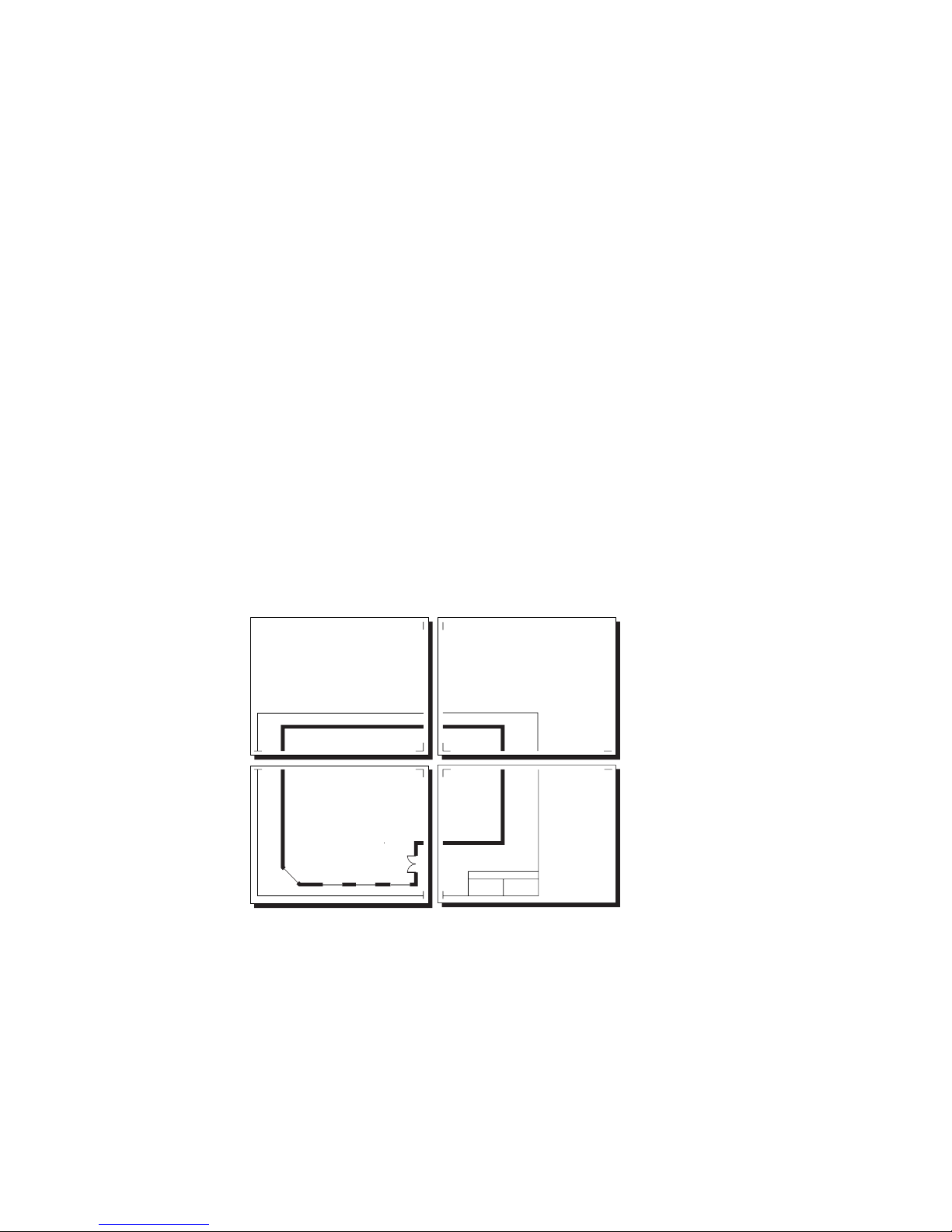
To cancel printing
■ Press ESC.
Understanding Page Tiling
If you create a drawing that is larger than a single printer page, AutoSketch
automatically tiles it across multiple pages. This gives you the flexibility to
generate large output on any printer. AutoSketch prints tick marks to indicate
the margins on tiled output. Before connecting the printed pages together,
you must first cut away the margin area indicated by the tick marks.
For example, let’s assume you have created a drawing using an 11'' x 17'' page
with a landscape orientation. However, your printer only supports 8.5'' x 11''
pages. In addition, you discover that there is a .25'' wide margin at all sides
of the printer page that the printer can’t print on. This means that you only
have an active printing area of 8'' x 10.5''.
Fortunately, AutoSketch can print this drawing using four printer pages tiled
together. When you print the drawing, four pages emerge from your printer.
Tick marks at the corners indicate the printable area and margins for each
printer page. These serve as a guide for splicing the pages together.
Understanding Page Tiling | 77
Page 88

Selecting an Output Device
AutoSketch normally prints your drawings using the current Windows
printer. However, you can print using any installed printer. The Print dialog
box allows you to specify a printer or plotter from among those that are
currently installed.
To set hardware parameters for an active printer
1 On the File menu, click Print. The Print dialog box appears.
2 Click a printer from the drop-down list box in the Printer section.
3 Make any changes that are necessary and click OK.
Printing a Drawing to Scale
Any output you plan to measure with an architectural or engineering scale
must be printed to scale. When you create scaled output, you can print the
entire drawing or a portion of the drawing. The scale used when printing is
the current drawing scale. For information on setting the drawing scale, see
“Setting the Drawing Scale” on page 47.
To print the entire drawing to scale
1 On the File menu, click Print. The Print dialog box appears.
2 In the View to Print drop-down list box, click Extent View.
3 In the Sizing Method drop-down list box, click Scaled.
4 To print the grid, check the Print Grid check box. For more information,
see “Setting Up the Grid” on page 61. Note that you must have the Show
Grid option selected in the View Options dialog box to print the grid.
5 Click OK.
To print part of the drawing to scale
1 On the File menu, click Print. The Print dialog box appears.
2 Click a view from the View to Print drop-down list box. Current View
prints the currently displayed view. Page View prints the onscreen page.
Extent View prints the entire drawing. Other items in this list print previously saved views. Marquee View prints the current marquee region (if
one is defined).
3 In the Sizing Method drop-down list box, click Scaled.
78 | Chapter 7 Printing, Plotting, and Publishing
Page 89

4 To print the grid, check the Print Grid check box. For more information,
see “Setting Up the Grid” on page 61. Note that you must have the Show
Grid option selected in the View Options dialog box to print the grid.
5 Click OK.
Printing a Drawing to Fit on a Page
Fitted output is useful anytime you need the largest image possible rather
than one printed at a specific scale. You cannot scale from fitted output.
However, AutoSketch provides the ability to automatically set the scale as a
compromise between fitted and scaled output. For information on setting
the scale automatically, see page 80.
To print the entire drawing on a single page
1 On the File menu, click Print. The Print dialog box appears.
2 In the View to Print drop-down list box, click Extent View.
3 In the Sizing Method drop-down list box, click Fitted to Printer Page.
4 To print the grid, check the Print Grid check box. For more information,
see “Setting Up the Grid” on page 61. Note that you must have the Show
Grid option selected in the View Options dialog box to print the grid.
5 Click OK.
To print part of the drawing on a single page
1 On the File menu, click Print. The Print dialog box appears.
2 In the View to Print drop-down list box, click a view.
■ Marquee View prints the current marquee region (if one is defined).
■ Current View prints the currently displayed view.
■ Page View prints the onscreen page.
■ Extent prints the entire drawing.
■ Other items in this list print previously saved views.
3 In the Sizing Method drop-down list box, click Fitted to Printer Page.
4 To print the grid, check the Print Grid check box. For more information,
see “Setting Up the Grid” on page 61. Note that you must have the Show
Grid option selected in the View Options dialog box to print the grid.
5 Click OK.
Printing a Drawing to Fit on a Page | 79
Page 90

To print all or part of the drawing as large as possible on multiple pages
1 On the File menu, click Page Setup. The Page Setup dialog box appears.
2 Click the Size page tab.
3 To specify the size to print in terms of printer pages, click the Tiling
Pattern option button. To specify the size to print using exact measurements, click the Custom Size option button. For more information on setting the page size, see “Setting the Page Size” on page 51.
4 Click OK.
5 On the File menu, click Print. The Print dialog box appears.
6 In the View to Print drop-down list box, click a view.
7 In the Sizing Method drop-down list box, click Fitted to Page.
8 To print the grid, check the Print Grid check box. For more information,
see “Setting Up the Grid” on page 61. Note that you must have the Show
Grid option selected in the View Options dialog box to print the grid.
9 Click OK.
Setting the Drawing Scale Automatically
When you need to print your drawing as large as possible on a single page,
AutoSketch can set the scale for you automatically. AutoScale causes
AutoSketch to choose a standard scale that displays your drawing as large as
possible on the page and it adjusts the drawing origin to center your drawing
on the page. AutoFit causes AutoSketch to choose a non-standard scale,
which may not meet certain building, or other, scale standards.
This procedure uses the File menu’s Page Setup and Print commands, and the
Tools menu’s Options command. For more information on setting the page
size, see “Setting the Page Size” on page 51. For more information on setting
the drawing scale, see “Setting the Drawing Scale” on page 47.
To print, setting the drawing scale automatically
1 On the File menu, click Page Setup. The Page Setup dialog box appears.
2 Click the Size page tab, click Printer Page, then click OK.
3 On the Tools menu, click Drawing Options. The Drawing Options dialog
box appears.
4 Click the Scale page tab, click AutoScale, then click OK.
5 On the File menu, click Print. The Print dialog box appears.
6 In the View to Print drop-down list box, click Page View.
80 | Chapter 7 Printing, Plotting, and Publishing
Page 91

7 In the Sizing Method drop-down list box, click Scaled.
8 To print the grid, check the Print Grid check box. For more information,
see “Setting Up the Grid” on page 61. Note that you must have the Show
Grid option selected in the View Options dialog box to print the grid.
9 Click OK.
Publishing a Drawing File Set using eTransmit
To make the drawings that you publish most effective, the transmittal must
include all associated files. With eTransmit, you can create a transmittal set
of an AutoSketch drawing that automatically includes all its related files. You
then publish the transmittal set as an email attachment. When you use
eTransmit, a report file is automatically generated that includes instructions
detailing what files are included in the transmittal set and what must be done
with them so that they are usable by the original drawing. You can also add
notes to the report and specify password protection for the transmittal set.
You can specify path options for the transmittal set and you can create a selfextracting executable or zip file that packages all the files. Once all options
are specified, eTransmit attaches the files to the email.
To create a transmittal set of individual files to send via email
1 From the File menu, choose eTransmit.
2 (Optional) Specify any additional comments to include with the report
file in Notes.
3 Select Set of Files from the Type list.
4 (Optional) To create a web page as part of the transmittal, check the Make
web page files check box. To customize your web page, you can edit the
template file that creates the web page. The template, eTransmit.htt, is
located in: Install Drive\Program Files\Autodesk\AutoSketch\Properties.
If you do not want to create a web page, uncheck the Make web page files
check box.
5 Choose OK to create the set of files attached to the email.
6 (Optional) Select the Files tab to view a list of the files to be included in
the transmittal set. By default, all files associated with the current drawing
are listed.
7 (Optional) To add additional files to the transmittal set, choose Add File
and browse to the file that you want to add.
8 (Optional) To remove a file from the transmittal list, uncheck the check
box next to the file you want to remove.
Publishing a Drawing File Set using eTransmit | 81
Page 92

9 (Optional) Select the Report tab to view report information that is
included with the transmittal set. Report information includes any transmittal notes that you entered on the General tab and distribution notes
automatically generated by AutoSketch.
10 (Optional) To save the report file, choose Save As and specify the file
name. Note that a report file is automatically included with all transmittal
sets that you generate; by choosing Save As, you can save an additional
copy of a report file for archival purposes.
To create a self-extracting executable or Zip file to send via email
1 From the File menu, choose eTransmit.
2 Select the General tab to define the transmittal.
3 (Optional) Specify any additional comments to include with the report
file in Notes.
4 Select one of the following from the Type list:
■ Self-Extracting Executable (*.exe)
■ Zip (*.zip)
5 (Optional) Choose Password to specify a password for the transmittal set
and do the following:
■ Enter a password in Password for Compressed Transmittal.
■ Re-enter the password in Password Confirmation.
■ Choose OK.
6 Specify the transmittal file name using one of the following from the Path
processing list:
■ Don’t preserve path
■ Preserve path without drive letter
■ Preserve path prepending virtual drive name
7 (Optional) To create a web page as part of the transmittal, check the Make
web page files check box. To customize your web page, you can edit the
template file that creates the web page. The template, eTransmit.htt, is
located in: Install Drive\Program Files\Autodesk\AutoSketch\Properties
If you do not want to create a web page, uncheck the Make web page files
check box.
8 Choose OK to create the transmittal set.
9 (Optional) Select the Files tab to view a list of the files to be included in
the transmittal set. By default, all files associated with the current drawing
are listed.
82 | Chapter 7 Printing, Plotting, and Publishing
Page 93

10 (Optional) To add additional files to the transmittal set, choose Add File
and browse to the file that you want to add.
11 (Optional) To remove a file from the transmittal list, uncheck the check
box next to the file you want to remove.
12 (Optional) Select the Report tab to view report information that is
included with the transmittal set. Report information includes any transmittal notes that you entered on the General tab and distribution notes
automatically generated by AutoSketch.
13 (Optional) To save the report file, choose Save As and specify the file
name. Note that a report file is automatically included with all transmittal
sets that you generate; by choosing Save As, you can save an additional
copy of a report file for archival purposes.
To unpack a self-extracting executable transmittal set
1 In Windows Explorer, double-click the transmittal set file.
2 In the eTransmit dialog box, choose Browse to specify the folder to unpack
the transmittal set files to.
3 Choose OK.
4 If the transmittal set is password protected, you are prompted to enter the
password.
5 The unpack status displays.
6 Choose OK to exit.
Publishing a Drawing to the Web
The Publish to Web wizard simplifies the process of creating DWF files and
formatting them for display in HTML pages.
The Publish to Web wizard provides a simplified interface for creating formatted Web pages that include DWF or JPEG images of AutoSketch drawings.
■ DWF format does not compress the drawing file.
■ JPEG format uses lossy compression; that is, some data is deliberately dis-
carded to greatly reduce the size of the compressed file.
NOTE To view DWF format drawing files, you will need to download a free
copy of Volo View Express from the Autodesk.com website.
Publishing a Drawing to the Web | 83
Page 94

Using Publish to Web, you can quickly and easily create an attractively for-
matted Web page, even if you are not familiar with HTML coding. After
creating a Web page, you can post it to an Internet or intranet location.
Following are some examples of ways in which you can use the Publish to
Web wizard to create a Web page:
■ Templates—You can choose one of four templates for the layout of your
Web page or customize your own template.
■ Theme—You can apply a theme to the template you’ve chosen. With
themes, you can modify the colors and fonts in your Web page.
You can also use the wizard to modify existing HTML pages that were created
using the PUBLISHTOWEB command.
NOTE You can customize any of the Publish to Web templates that you use for
your Web page.
To use the Publish to Web wizard
1 From the File menu, choose Publish to Web
2 Follow the instructions to generate a Web page.
Customizing a Publish to Web Template
You can customize the Publish to Web templates provided with AutoSketch
by modifying an existing Publish to Web template (PWT) file. You can use
any HTML editor or text editor to customize a template.
Some of the customizations you may want to make in a template include
adding or modifying the following:
■ Images
■ Text
■ Hyperlinks
■ Color
■ Title
■ Video, animation, and so on
84 | Chapter 7 Printing, Plotting, and Publishing
Page 95

AutoSketch provides four types of Publish to Web templates that you can
customize:
■ Array of Thumbnails—Creates a Web page containing an array of thumb-
nail images.
■ Array Plus Summary—Creates a Web page containing an array of thumb-
nail images and summary information about an image.
■ List of Drawings—Creates a Web page containing a list of drawings and an
image frame.
■ List Plus Summary—Creates a Web page containing a list of drawings, an
image frame, and summary information about a selected image.
NOTE You must be familiar with HTML syntax in order to customize the
Publish to Web templates.
You can make changes or additions to the look and feel of a template, but you
cannot change the arrangement of images within it. For example, in the
Array of Thumbnails template, the images are presented across the page in
rows. You cannot alter the presentation of the images, but you can wrap text
and graphics around this table of images.
NOTE You can also create your own themes or edit the themes provided with
AutoSketch. To change the color scheme of existing themes, edit the appropriate .ccs file and corresponding .bmp file located in the Install Drive\Program
Files\Autodesk\AutoSketch\Templates\PTWTemplates\Support folder. To add
new themes, add the .ccs and .bmp files to the same folder. The name of the
themes that appear in the Publish to Web - Apply Theme dialog box are specified
in the .ccs file. The corresponding sample .bmp files are also in the .ccs file.
NOTE To ensure that you do not overwrite the AutoSketch Publish to Web
template or theme files, back up these files before you make any changes to
them.
To customize a Publish to Web template
1 Access the existing AutoSketch Publish to Web template folder by navigat-
ing to the following location:
Install Drive\Program Files\Autodesk\AutoSketch\Templates\PTWTemplates
Customizing a Publish to Web Template | 85
Page 96

In the PTWTemplates folder, there are four subdirectories, each containing a Publish to Web template and preview images (BMP) that you see
when you run the Publish to Web wizard:
■ Template1—Contains the Array of Thumbnails template and a preview
image
■ Template2—Contains the Array Plus Summary template, a preview
image, and HTML frames
■ Template3—Contains the List of Drawings template, a preview image,
and HTML frames
■ Template4—Contains the List Plus Summary template, a preview
image, and HTML frames
2 Select the template folder containing the template you want to modify
3 Copy the template folder and all of its contents, paste it into the
PTWTemplates folder, and rename the new folder.
4 Rename the Publish to Web template (PWT) file with an HTM or HTML
extension.
5 Open the template file in an HTML editor or text editor.
The template file contains comments that help you determine which
areas of the code you can modify to create your new Web page.
6 Review the comments and make changes to parts of the template you
want to customize.
7 Save the template with a .pwt extension. Make sure you save the file to the
template folder you created in step 3.
NOTE Each template folder can contain only one PWT file. If you’ve created
a new PWT file, make sure you delete any other PWT files that exist in the
same folder.
8 When you run the Publish to Web wizard, your template appears in the
list of templates. You can now begin to produce Web content with your
own HTML creations.
86 | Chapter 7 Printing, Plotting, and Publishing
Page 97

Controlling Views
8
AutoSketch provides many options for looking at your
drawing onscreen. You can display several windows or
panes, each containing different drawings or different
views of the same drawing. Additionally, AutoSketch
features many tools for modifying your view directly—
tools that allow you to zoom or pan dynamically or by
increments.
AutoSketch also offers a number of preset views
designed to quickly give you the views you use the most.
If you find that you need quick access to other areas of
your drawing, you can save and recall your own views.
In this chapter
■ Viewing several areas at
once
■ Using preset views
■ Zooming in and out
■ Panning across the
drawing
■ Using the IntelliMouse
■ Returning to a
previous view
■ Saving and recalling views
■ Viewing drawing details
■ Redrawing a pane
or window
■ Arranging drawing
windows
87
Page 98

AutoSketch provides many options for looking at your drawing onscreen.
You can display several windows, each containing the same or different
drawings. Each window can display one, two, or four panes at a time. Each
pane can contain a different view of the drawing. This gives you the flexibil-
ity to see all of the areas of a drawing that you need at any given time, from
highly magnified detail views to broad overviews of the entire drawing.
In addition, AutoSketch provides a number of commands designed to let you
choose the exact view you want for any window or pane.
■ Realtime Zoom allows you to zoom in and out of the drawing dynamically,
instantly changing the view as you move the mouse.
■ Realtime Pan allows you to pan across the drawing dynamically.
AutoSketch also offers a number of preset views designed to quickly give you
the views you use the most. If you find that you need quick access to other
areas of your drawing, you can save and recall your own views.
Using the View Options dialog box, you can customize the AutoSketch draw-
ing window to fit your needs, including changing the screen, reference grid,
and drawing page. For more information, see online Help.
View commands can be accessed from the View menu or the View toolset on
the All-In-One toolbar. You can also activate the View toolbar (which con-
tains the same commands but can be docked anywhere onscreen) by right-
clicking a bar, then clicking Toolbars on the pop-up menu that appears.
Simply check View in the Toolbars dialog box, then click OK to make the
View toolbar visible onscreen.
Viewing Several Areas at Once
To work on different parts of a drawing at the same time, you can open
additional windows or split a window into several panes. Both methods
create independent views that you can draw or edit between. You split a
window by draggin g the split bar s or by clicking Split on the drawing window
Control menu. The UnSplit command restores the active window to a single
pane. When you edit the drawing in one pane, the other views also display
the changes. When the drawing window is split into multiple panes, the
active pane indicator marks the active pane.
When you open a new drawing window, it becomes the active window. You
can change how drawing windows are arranged by using the commands on
the Window menu. For information on arranging multiple drawing
windows, see page 97.
88 | Chapter 8 Controlling Views
Page 99

To split the drawing window into multiple panes
■ Click the Split command on the drawing window Control menu, or drag
either the horizontal split bar down from the top of the window or the
vertical split bar to the right from the left side of the window, or doubleclick either split bar.
To return the drawing window to a single pane
■ Click the UnSplit command on the drawing window Control menu, or
drag either the horizontal or vertical split bar back to its original location
at the top and left sides of the display, respectively, or double-click either
split bar.
To open another window for the active drawing
■ On the Window menu, click New Window.
To change the active pane
■ Click the pane indicator or press F6. F6 makes the next pane active.
SHIFT+F6 makes the previous pane active.
Viewing Several Areas at Once | 89
Page 100
Using Preset Views
AutoSketch provides several common views. These preset views can be a use-
ful starting point before zooming in on a specific region. The page view
shows your drawing as it appears when printed, in most cases. The extent
view displays all entities in the drawing. The selection view shows the extent
of the currently selected entities. For each of these preset views, AutoSketch
provides a corresponding command on the window Control menu that sets
the view for all panes of a split window.
To view the page
■ On the View menu, click Page, or click the View Page button on the All-
In-One toolbar. To view the page in all panes of a single window, on the
drawing window Control menu, click View All, Page.
To view all entities in a drawing
■ On the View menu, click Extent, or click the View Extent button on the
All-In-One toolbar. To view all entities in all panes of a single window, on
the drawing window Control menu, click View All, Extent.
To view the selection set
1 Select an entity or group of entities.
2 On the View menu, click Selection, or click the View Selection button on
the All-In-One toolbar. To view all entities in all panes of a single window,
on the drawing window Control menu, click View All, Selection.
NOTE You can also view the selection set by clicking View Selection on the
pop-up menu for the selection set. To display the menu, position the pointer
inside the selection handles, but not on the about point, of a selection set,
and right-click.
Zooming In and Out
You can get a closer look at an area or see a larger portion of the drawing by
zooming in or out. You can use the mouse or the keyboard to change the
view magnification. The mouse offers more control over the view, while the
keyboard allows you to quickly change the magnification by a preset
amount.
90 | Chapter 8 Controlling Views
 Loading...