

Page 1

17-INCH TALENT FEEDBACK MONITOR
ASSEMBLY AND INSTALLATION GUIDE
Page 2

Assembly and Installation
Guide
Autocue and QTV have been serving the broadcast industry since the mid-1950s
when QTV in New York and Autocue in London supplied the very first prompters
via their rental divisions.
Creating broadcast history. The two companies merged in 1984
under Autocue Group and, with the introduction of the QSeries family of software,
became the only company to offer the television industry a single solution for all
transmission, newsroom, scripting and prompting requirements. QTV forms the
Americas division of Autocue Group’s prompting sales and rental services.
Prompter of choice around the globe. Autocue Group is known
worldwide for its service and dependability, serving such prestigious clients as the
BBC, Bloomberg, NBC and CNN. The Group’s prompting solutions are compatible
with all newsroom systems on the market and are in use worldwide by broadcasters, production professionals, government facilities and corporate producers
TFM17
requiring excellence in prompting and newsroom automation solutions.
For further information, please visit either web site shown at the bottom of this
page.
Issue #: 081017 ©2003-2008 Autocue Group Ltd
www.qtv.com
ii
www.autocue.com
Page 3

TFM17 Assembly and Installation Guide
Contents
Contents .............................................................................................iii
1 Introduction.........................................................................................1
1.1: TFM17.............................................................................................................1
1.2: About this guide...............................................................................................1
1.3: Copyright information......................................................................................2
1.4: Disclaimer........................................................................................................2
2 TFM17 Components ...........................................................................3
2.1: Supplied equipment.........................................................................................3
2.2: Optional equipment.........................................................................................4
3 TFM17 Technical Specifications .......................................................5
4 TFM17 Connections............................................................................ 6
4.1: Physical characteristics...................................................................................6
4.1.1: Video and power inputs......................................................................6
5 Assembly Procedures........................................................................7
5.1: Mounting a TFM17 on an Autocue “Magic Arm” .............................................7
5.1.1: Attach “Magic Arm” to the mounting plate..........................................7
5.1.2: Attach monitor to the “Magic Arm”......................................................8
5.1.3: Position monitor below OCU ..............................................................8
5.2: Attach Magic Arm mounting plate to OCU bracket..........................................9
6 TFM17 Operation ..............................................................................12
6.1: Connections ..................................................................................................12
6.2: Operating your TFM17..................................................................................12
7 Troubleshooting and Maintenance .................................................13
7.1: Common problems........................................................................................13
7.2: Maintenance..................................................................................................14
7.2.1: Cleaning the monitor ........................................................................14
7.2.2: Care and handling advice.................................................................14
8 Sales and Support Information .......................................................16
Sales information...........................................................................................16
Technical support..........................................................................................17
Issue #: 081017 ©2003-2008 Autocue Group Ltd
www.qtv.com
iii
www.autocue.com
Page 4

TFM17 Assembly and Installation Guide
SECTION 1:
Introduction
For the broadcaster, production facility or event organiser requiring greate r viewing
distances and larger display areas, Autocue prompter display and on-camera units
satisfy all your needs.
Designed for the most demanding of broadcast environments, Autocue on -camera
units and feedback monitors have crisp, ultra-bright picture quality, precision
controls, and rugged construction.
Autocue on-camera units comprise prompter display, hood, mounting bracket,
tripod plate and accessories.
Autocue on-camera units and feedback monitors are available in a range of configurations to match most camera, lens and mounting combinations.
1.1: TFM17
Autocue’s Talent Feedback Monitors (TFMs) provide on-camera talent with
precise, live broadcast output. Conveniently mounted below the prompter unit with
a fully adjustable mounting arm, complete range of motion is achieved for
maximum visibility.
A variety of counterbalances and adjustable weights are available to ensure safe
and stable operation and movement of mounted equipment.
Where appropriate, Autocue can also provide a range of accessories, such as cue
lights and remote controls, to complement your chosen system.
1.2: About this guide
This document describes how to assemble and mount your chosen Autocue
prompter display or on-camera unit. It is suitable for any broadcaster or news
Issue #: 081017 ©2003-2008 Autocue Group Ltd
www.qtv.com
1
www.autocue.com
Page 5

TFM17
Assembly and Installation
Guide
production crew. This guide is suitable for novices as well as expert users of the
product line from Autocue.
Reference material is also provided that explains how to adjust the various settings
and troubleshoot the prompters to ensure optimum performance.
1.3: Copyright information
©2004-2008 Autocue Group Ltd. All rights reserved.
No part of this publication may be reproduced, stored in a retrieval system, or trans-
mitted in any recording or otherwise, without prior permission of Autocue Group
Ltd.
All third-party software or hardware, including logos, referenced within this guide is
copyright of the respective owners.
Section 1: Introduction
Copyright information
1.4: Disclaimer
Autocue Group Ltd reserves the right to revise this publication and to make
changes in its content without obligation of Autocue Group Ltd to notify any person
or persons of such revision.
Issue #: 081017 ©2003-2008 Autocue Group Ltd
www.qtv.com
2
www.autocue.com
Page 6
TFM17 Assembly and Installation Guide
SECTION 2:
TFM17 Components
The following tables list the supplied and recommended components for your
TFM17 on-camera unit.
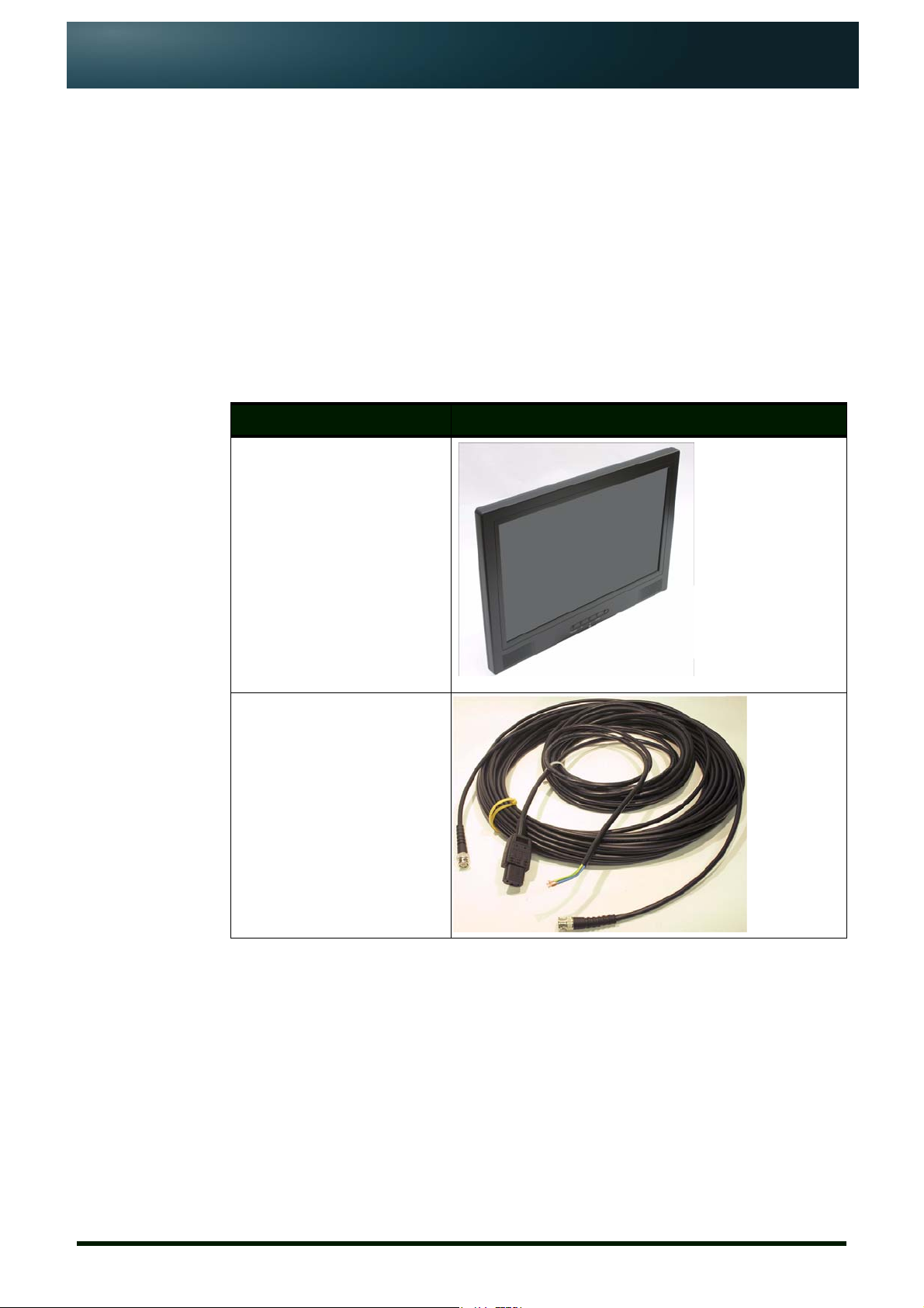
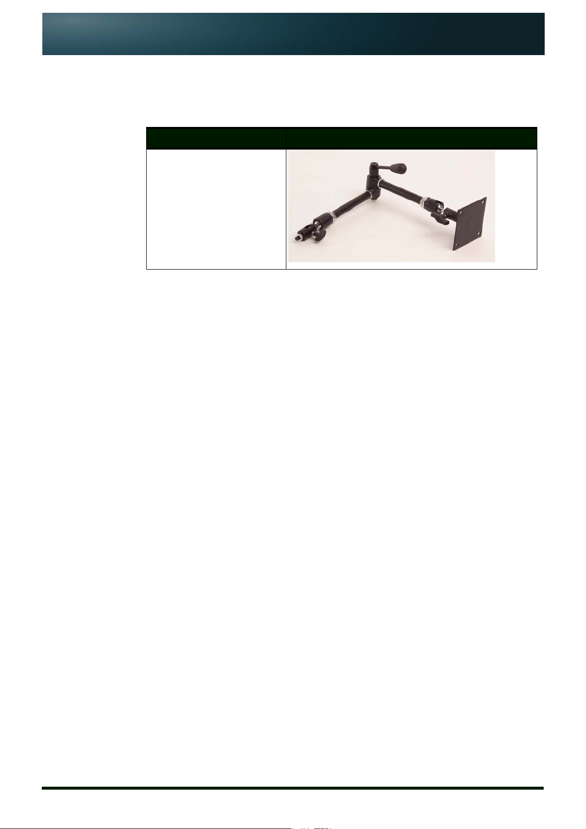
2.1: Supplied equipment
Item Name Illustration
TFM17
Power and video cable
Issue #: 081017 ©2003-2008 Autocue Group Ltd
www.qtv.com
3
www.autocue.com
Page 7
TFM17
Assembly and Installation
Guide
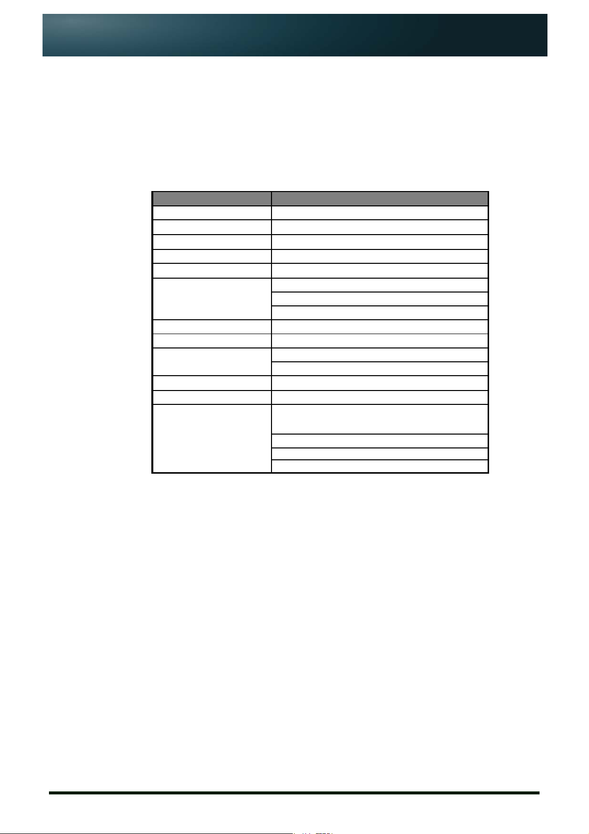
2.2: Optional equipment
Item Name
Large “Magic Arm” bracket
Section 2: TFM17 Components
Optional equipment
Issue #: 081017 ©2003-2008 Autocue Group Ltd
www.qtv.com
4
www.autocue.com
Page 8
TFM17 Assembly and Installation Guide
SECTION 3:
TFM17 Technical
Specifications
ATTRIBUTE VALUE
Display size
Brightness
Resolution
Contrast Ratio
Reading range
Input signal
Compos ite standard
Power input
Power consumption
Display controls
Assembly weight
Common mounting
options
17” (432mm)
400 Nits
1440 x 900
200 : 1
5m (16ft)
Composite (1 x BNC)
VGA
S-video
NTSC, PAL
12 V D C (2.1 mm jack)
36W
3A @ 12V DC
Push button on-screen menu
~ 4 kg
“Magic Arm” Bracket:
Light wei ght system
Attaches to the wide-angle hood bracket
Fully adjustable to any height or angle of view
Issue #: 081017 ©2003-2008 Autocue Group Ltd
www.qtv.com
5
www.autocue.com
Page 9

TFM17 Assembly and Installation Guide
SECTION 4:
TFM17 Connections
4.1: Physical characteristics
The Autocue TFM17 is illustrated below.
4.1.1: Video and power inputs
Connect video cables and power leads to the sockets on the side of the .prompter
display unit.
Power. Use either a standard mains electrical supply cable to the Mains Input
socket.
Video. You can connect a video signal via the Video In BNC.
Issue #: 081017 ©2003-2008 Autocue Group Ltd
www.qtv.com
6
www.autocue.com
Page 10
TFM17 Assembly and Installation Guide
SECTION 5:
Assembly Procedures
An Autocue Talent Feedback Monitor (TFM) can be used with almost any industrystandard camera and tripod combination. The TFM17 is usually used in conjunction
with Autocue’s larger On-Camera Units.
Assembling and mounting your TFM17 involves:
• attaching the mounting arm to the OCU mounting plate
• attaching the monitor to the mounting arm
• connecting required cables
• ensuring all connections and fixings are secure.
The TFM17 is supplied with the mounting plate already attached to the back of the
monitor using standard VESA fittings.
NOTE: A feedback monitor is usually ordered at the same time as
OCU with the mounting plate already attached to the OCU
mounting bracket. If TFM17 is ordered separately refer to
section 5.2 for instructions on attaching the mounting plate to
the OCU bracket.
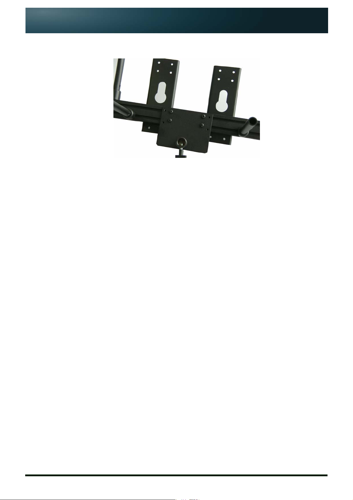
5.1: Mounting a TFM17 on an Autocue “Magic Arm”
Talent feedback monitors should be attached to Autocue’s standard OCU mounting
bracket using the recommended “Magic Arm” bracket.
5.1.1: Attach “Magic Arm” to the mounting plate.
1. Insert one end of the “Magic Arm” bracket into the mounting plate
attached to the OCU mounting bracket.
2. Securely fasten the locking screw.
Issue #: 081017 ©2003-2008 Autocue Group Ltd
www.qtv.com
7
www.autocue.com
Page 11

TFM17
Assembly and Installation
Guide
Mounting a TFM17 on an Autocue “Magic Arm”
NOTE: The vertical hood mounting bars are longer than the horizontal
prompter display unit mounting bars.
5.1.2: Attach monitor to the “Magic Arm”
1. Insert the end of the “Magic Arm” into the socket of the plate on the rear
of the TFM17.
Section 5: Assembly Procedures
Attach monitor to the “Magic Arm”
2. Securely fasten the locking screw.
5.1.3: Position monitor below OCU
1. Loosen the central locking lever of the “Magic Arm” bracket..
2. Carefully maneuver the TFM17 to the required position.
Issue #: 081017 ©2003-2008 Autocue Group Ltd
www.qtv.com
8
www.autocue.com
Page 12

TFM17
Assembly and Installation
Guide
Section 5: Assembly Procedures
Attach Magic Arm mounting plate to OCU bracket
Position monitor below OCU
3. Securely lock the whole assembly in place by tightening the central
locking lever.
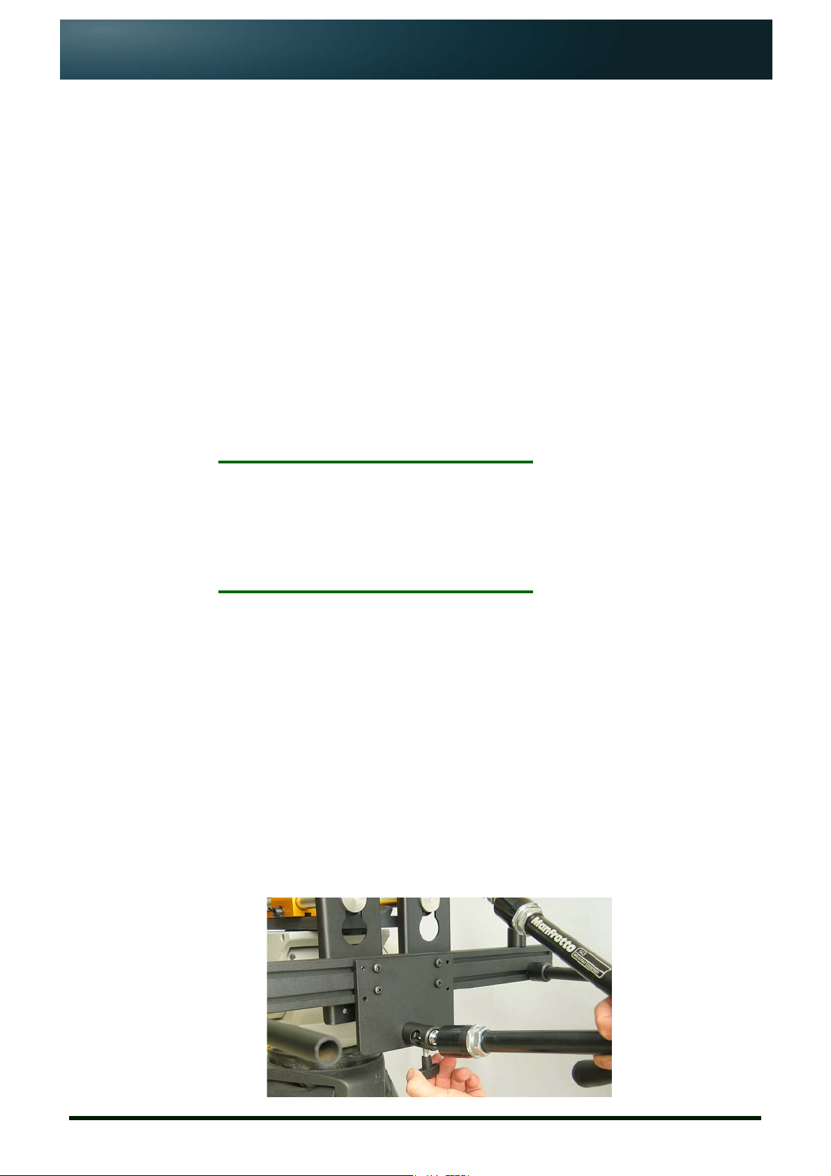
5.2: Attach Magic Arm mounting plate to OCU bracket
If you have purchased a TFM17 as a separate item, you will need to attach the
monitor plate to the OCU mounting bracket.
1. Remove the wide angle hood and prompter display monitor from the
OCU mounting bracket.
2. Detach the mounting bracket from the tripod mounting plate.
Issue #: 081017 ©2003-2008 Autocue Group Ltd
www.qtv.com
3. Remove one of the horizontal mounting bars
9
www.autocue.com
Page 13

TFM17
Assembly and Installation
Guide
Section 5: Assembly Procedures
Attach Magic Arm mounting plate to OCU bracket
Position monitor below OCU
4. Carefully remove the plastic end caps from the mounting bracket using a
thin screwdriver or similar device
5. Insert two of the supplied slide nuts into each of the slots of the mounting
bracket. Ensure these are are on the same side as the horizontal
mounting bars.
6. Position the four slide nuts to align with the screws of the “Magic Arm”
mounting plate.
7. Securely fasten the mounting plate to the OCU mounting bracket.
Issue #: 081017 ©2003-2008 Autocue Group Ltd
www.qtv.com
10
www.autocue.com
Page 14
TFM17
Assembly and Installation
Guide
Section 5: Assembly Procedures
Attach Magic Arm mounting plate to OCU bracket
Position monitor below OCU
8. Replace the plastic end caps and re-attach the horizontal mounting bar
that was remover in step 1 above.
9. Replace the OCU bracket assembly on to the tripod mounting plate.
Issue #: 081017 ©2003-2008 Autocue Group Ltd
www.qtv.com
11
www.autocue.com
Page 15

TFM17 Assembly and Installation Guide
SECTION 6:
TFM17 Operation
OSD (On Screen Display) menus are used to configure the TFM17 and prepare it
for displaying scripts.
NOTE: While operating your TFM17, troubleshooting or maintenance
tasks may need to be performed on the prompter display unit.
For guidance, refer to section 7.
6.1: Connections
Once your TFM17, on-camera unit and camera combination are securely mounted
on a tripod attach the TFM17 cabling.
NOTE: Ensure you have a power supply and video signal available.
1. Connect the video signal to the appropriate input socket.
2. Connect the IEC power cable to the power input socket.
6.2: Operating your TFM17
Turn on the TFM17 and if necessary, use the control buttons to adjust the
positioning and appearance of the image displayed.
All units are checked before being shipped using the default factory settings.
Depending on the ambient lighting conditions where you will be operating the
TFM17, you may need to adjust the brightness and contrast of the image.
Issue #: 081017 ©2003-2008 Autocue Group Ltd
www.qtv.com
12
www.autocue.com
Page 16

TFM17 Assembly and Installation Guide
SECTION 7:
Troubleshooting and
Maintenance
7.1: Common problems
The table below lists common problems that may occur during prompter operatio n.
Suggested things to look for are.
Problem Check...
The power LED of the LCD flatpanel display is not illuminated
There is no picture visible if the power supply receives power and is
if the power switch for the unit is in the ON
position
if the power cord is connected to a working
power outlet.
if the power cord is plugged in to the unit
correctly connected to the display
if the signal cable is correctly connected to the
graphics board or to the video source and
display
if the device is it turned on and set to the
correct mode (VGA or video)
if the display supports the graphics mode of
the graphics board (see Technical
Specifications)
Issue #: 081017 ©2003-2008 Autocue Group Ltd
if the connectors have any bent pins
if the brightness and contrast settings in the
OSD menu are appropriate
if the screen saver settings of your system are
causing problems
The power LED is red See previous item #2.
The image is blurred or unstable if the signal cable is correctly connected
if the selected graphics mode is correct.
if the display supports the graphics mode of
the graphics board.
if the resolution of the unit is set to less than
1280 x 1024 at a refresh rate of 60 Hz.
(For resolutions lower than this the image is
expanded via interpolation which may cause
errors. As a result the image may look
blurred.)
Alternative suggested remedies:
Select "Auto adjust" from the Position menu.
www.qtv.com
13
www.autocue.com
Page 17

TFM17
Assembly and Installation
Guide
Problem Check...
The image is not sized properly or
not centered
Section 7: Troubleshooting and Maintenance
Maintenance
Cleaning the monitor
Select the H-Total and Phase functions from
the Position menu and change the settings to
achieve a sharp and stable image (these
settings may have to be repeated when you
have selected another graphics mode).
if the horizontal and vertical image position in
the OSD menu is set correctly
If the selected graphics mode is appropriate
if the display unit supports the graphics mode
of the graphics board
OSD error message: "Signal
overrange”
For further troubleshooting assistance, refer to our Frequently Asked Questions
(FAQ) database on our website: www.autocue.com.
7.2: Maintenance
7.2.1: Cleaning the monitor
CAUTION: Electric Shock Hazard!
Isolate the feedback monitor and any other devices from any power
source before cleaning the display unit surface.
if the selected graphics mode is correct.
if the display unit supports the graphics mode
of the graphics board
Regular cleaning will help keep your feedback monitor in good condition.
• As recommended by the manufacturers, use tepid water with a
small amount of detergent to clean the glass on the prompter
display unit and then leave it to dry naturally.
• Wipe the equipment surface down with a moist cloth; do not
allow liquid to enter the equipment.
• Clean the feedback monitor screen with a lint-free, soft cloth. Do
not use (glass) cleaning agents or paper tissues for cleaning.
• Wait until all cleaned parts are completely dry before
reconnecting the feedback monitor to the power source.
7.2.2: Care and handling advice
• Avoid dropping the feedback monitor or any of its individual
components.
• Clean the monitor periodically.
Issue #: 081017 ©2003-2008 Autocue Group Ltd
www.qtv.com
14
www.autocue.com
Page 18

TFM17
Assembly and Installation
Guide
Section 7: Troubleshooting and Maintenance
Maintenance
Care and handling advice
NOTE: Do not use abrasive cleaners or dusters when cleaning the
monitor.
• Do not run the feedback monitor for excessively long periods of
time.
• Do not use in wet weather without a cover.
• Do not expose to sunlight for long periods of time.
• Ensure that the feedback monitor is correctly aligned both
horizontally and vertically for optimum viewing.
• Ensure that the whole assembly—camera, OCU, feedback
monitor—is securely fastened and does not sway from side to
side.
Issue #: 081017 ©2003-2008 Autocue Group Ltd
www.qtv.com
15
www.autocue.com
Page 19

TFM17 Assembly and Installation Guide
SECTION 8:
Sales and Support
Information
We have been working in live broadcast environments for the past 50 years
and understand the importance of efficient and effective hardware and
software support.
We provide the latest prompting software builds for free on our website ensuring
you continue to benefit from enhancements. Warranties cover all of our hardware
products, with an in-house assessment and repair service offered outside of the
warranty period.
Sales information
International enquiries
Autocue
Unit 3, Puma Trade Park Tel: +44 20 8665 2992
145 Morden Road Fax: +44 20 8687 4869
Mitcham e-mail: info@autocue.co.uk
Surrey web: www.autocue.com
CR4 4DG
UK
Contacts
Richard Satchell - Global Prompting Sales & Marketing Director
Tel: +44 20 8687 4858
Fax: +44 20 8687 4869
Mob: +44 77 2081 3897
e-mail: sales@autocue.co.uk
Simeon Pearl - International Sales Associate
Tel: +44 20 8687 4858
Fax: +44 20 8687 4869
e-mail: sales@autocue.co.uk
Issue #: 081017 ©2003-2008 Autocue Group Ltd
www.qtv.com
Lee Spurway - Sales Customer Service Manager
Tel: +44 20 8687 4862
Fax: +44 20 8687 4869
e-mail: sales@autocue.co.uk
16
www.autocue.com
Page 20

Assembly and Installation
Guide
Americas enquiries
QTV
306 5th Avenue Tel: +1 212 929 7755
3rd Floor Fax: +1 212 929 2105
New York e-mail: info@qtv.com
10001-3600 web: www.qtv.com
USA
Contacts
Keith Andoos - Sales Director (Americas)
Tel: +1 212 929 7755
Fax: +1 212 929 2105
Mob: +1 516 353 0113
kandoos@qtv.com
Section 8: Sales and Support InformationTFM17
Aaron Brady - Sales Manager
Tel: +1 212 929 7755
Fax: +1 212 929 2105
Mob: +1 516 528 3599
e-mail: sales@qtv.com
Technical support
Our hardware and software support is provided by our own in-house teams.
Telephone support
We provide 24/7 support for our QSeries and Rental customers, with support for
prompting customers available during UK office hours (9am till 6pm GMT) and US
office hours (9am till 5pm EST).
Onsite support
Our Tech Support team also travel to customer sites to install QSeries systems and
offer ongoing after-sales support to QSeries customers.
International
Issue #: 081017 ©2003-2008 Autocue Group Ltd
www.qtv.com
To request technical support please use one or more of the following options.
Phone.
1. Call the main Autocue number:
+44 20 8665 2992
2. Select the support option
17
www.autocue.com
Page 21

Assembly and Installation
Guide
Email.
Web site.
Section 8: Sales and Support InformationTFM17
3. Leave a message including as much detail about the problem as
practical.
1. Send an email to:
support@autocue.co.uk
Remember to include as much detail as possible. A phrase such as
“Screen blank” makes it difficult for the support staff to diagnose a
problem and will delay providing you with an answer.
1. Go to www.autocue.com
2. Select "Support" and then "Problem Form" from the menu bar
3. Complete the form and submit it.
Americas
Phone.
1. Call the main QTV number:
+1 704 377 1496
2. Select the support option
3. Leave a message including as much detail about the problem as
practical.
Email.
1. Send an email to:
support@qtv.com
Remember to include as much detail as possible. A phrase such as
“Screen blank” makes it difficult for the support staff to diagnose a
problem and will delay providing you with an answer.
Web site.
1. Go to www.qtv.com
2. Select "Support" and then "Problem Form" from the menu bar
3. Complete the form and submit it.
Issue #: 081017 ©2003-2008 Autocue Group Ltd
www.qtv.com
18
www.autocue.com
 Loading...