

Page 1

Autocue Limited.
Unit 3 Puma Trade Park,
145 Morden Road, Mitcham,
Surrey CR4 4DG
Tel; +44 (0)20 8665 2992
P.C. 90
Conference Stand
Page 2

Notice
Notice
NoticeNotice
DISCLAIMER
Autocue Ltd. reserves the right to revise this publication and to make
changes to it’s content without prior notification.
COPYRIGHT
Copyright 2001 Autocue Ltd.
PC 90 MANUAL
All rights reserved.
No part of this publication may be reproduced, stored in a retrieval system
or transmitted in any recording or otherwise without prior permission of
Autocue Ltd.
VERSION 1.0
Version 1.00 of this manual was written and compiled by
Autocue Ltd. 27 February 2008
2
AUTOCUE 2001
Page 3

PC 90 MANUAL
PC 90 Conference Stand.
How to use this guide.
Autocue PC90 Guide provides detailed information on how to set up and
operate the Autocue PC 90 Conference Stand.
Structure of this guide.
Modular in design, and divided into three simple chapters.
Chapter 1 Installation.
Chapter 2 Care.
How to install the Autocue PC90
Describes how to care for the Autocue
PC 90 with simple do’s and don’ts.
VERSION 1.0
Chapter 3 Technical Information
Frequently Asked Questions
Describes the specifications of the
Autocue PC 90.
3
AUTOCUE 2001
Page 4
1
1.
3.
Chapter
Installation for Autocue PC 90
In this chapter describes the requirements needed to use the Autocue
PC 90 MANUAL
PC 90
in easy to follow instructions.
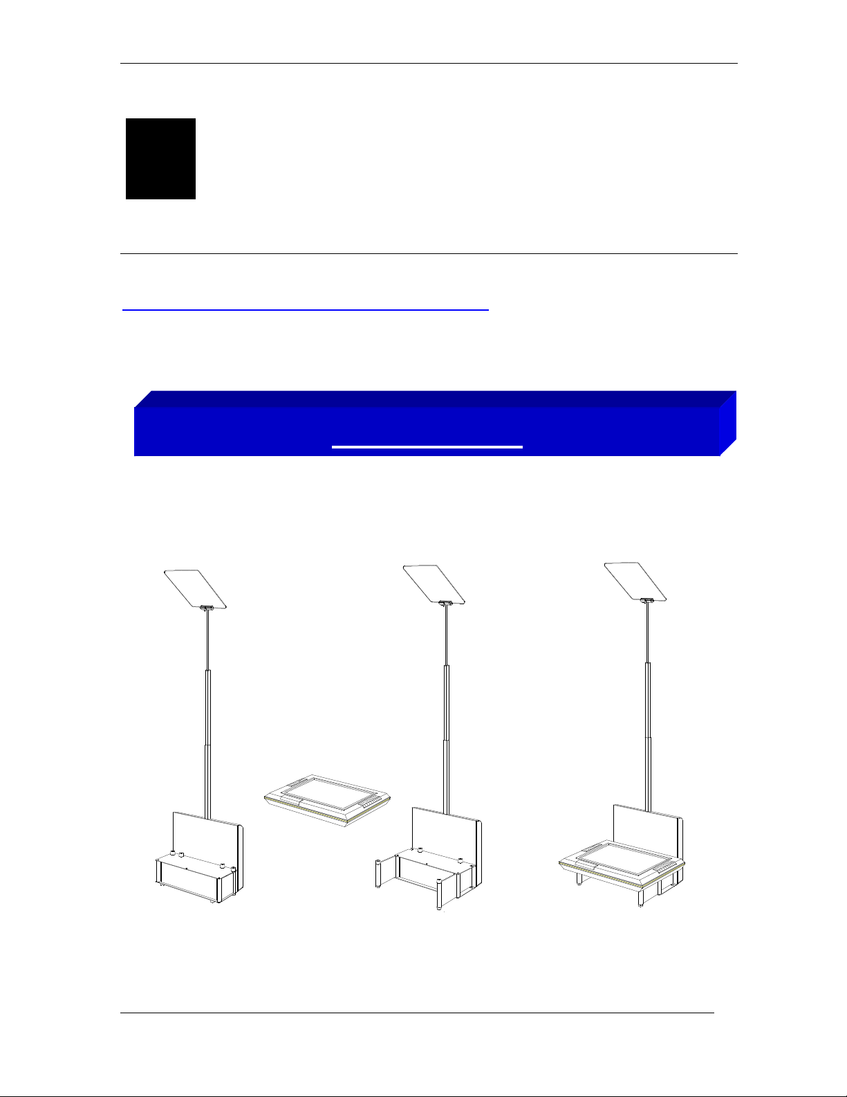
The installation of Autocue’s PC 90 is simple and can be covered in 3 easy steps.
System Set-up
1. Place the PC 90 on a level surface and open the support doors.
2. Stand the 15” FDP Monitor or 17” CRT Monitor onto the PC 90. (15” FDP Monitor shown.)
3.
Ensure that the unit is stable by adjusting the angle of the support doors.
VERSION 1.0
4
2.
AUTOCUE 2001
Page 5

PC 90 MANUAL
Glass Holder
be set at
monitor. Please insure that the
Clamp Screw
2.
3
Cable Set
-
up
Glass
Glass Holder
To install the glass into the
holder first loosen the clamp
screw so that the jaws of the
clamp are open. Insert the
glass and secure in the clamp
by retightening the clamp
screw. The angel of the glass
is adjustable and must
45 degrees to the face of the
blue dot on the face of the
glass is facing the presenter.
VERSION 1.0
Attach all relevant cables.
1. Power input.
2. Power output for monitor
3. Data input
4. Local control socket
5. Data output.
1.
4.
5.
5
AUTOCUE 2001
Page 6

PC 90 MANUAL
Power Input
Power Output to Monitor
Local Control
Power 230 v
Data Cable
Cable Set-up
Data Cables
Use the data cables to connect the remote control box to the PC 90 stands.
The data cables can be looped through the stands by using the Data input and
Data output sockets. Use the power output socket to power the monitor.
VERSION 1.0
6
AUTOCUE 2001
Page 7

PC 90 MANUAL
A maximum of 8 stands can be controlled in this way.
Stand Number Selector
Stand Configurations (Individual)
Set to No 1. Set to No 2. Set to No 3.
In this mode the PC90’s work on the principle of one stand at a time being controlled individually. The stands must be numbered 1 to 9 use
the Stand number selector switch that is located on the ‘Shoulder of each stand to change the number.
When the stand number 1 is selected and a new height is entered stand 1 will move to the new height.
VERSION 1.0 7 AUTOCUE 2001
When the stand number 2 is selected and a new height is entered stand 2 will move to the new height.
Page 8

you to
Number
Move
Stop
Cancel
stand number selected, and the new
Stand
Number
Current
Height
New
Height
PC 90 MANUAL
Remote Control Operation
The remote control panel will
control PC 90 stands individually
or in groups. It will display the
current height of the stands, the
When all the stands are correctly connected and powered and switched on, the Remote Control Box will take a few seconds to
automatically detect any stands that are connected to the system.
Buttons
Select
Stand
Set
Height
Operation
Press Select Stand and input the required stand number (1,2,3) using the number keys, the new stand number is now displayed in the
Stand Number window. The “Current Height” of the selected stand will be displayed in the Current Height window on the Remote Control
Box. At the stands, set the required height of each individual speaker by using the Local Control, making a note of the Current Height displayed
on the Remote Control Box. To move the stands to the pre-determined heights, press Select Stand and enter the number (1,2,3), then press Set
height and enter the required height number 01 to 84. The new height will be displayed in the New Height window. Now press Move, the stand
VERSION 1.0 8 AUTOCUE 2001
or group of stands will now move to the new height entered. Pressing the Stop button will stop the command and the Cancel button enables
change the Stand Number and Stand Height.
height you wish the stand to move
to.
Page 9

In this mode the PC90 works on the principle of one Master and one or more slave stands in each group. The master stand in each group must be
Stand Configurations (Grouped Stands)
PC 90 MANUAL
Group 1
Group 2
Set to No 1. Set to No 9. Set to No 2. Set to No 0.
numbered either 1 or 2, using the Stand number selector switch that is located on the ‘Shoulder of each stand.
The Slave Stand or Stands of number 1 must be numbered 9. The slave Stand or Stands of number 2 must be numbered 0.
When the stand number 1 is selected and a new height is entered all stands in-group 1 will move to the new height.
VERSION 1.0 9 AUTOCUE 2001
When the stand number 2 is selected and a new height is entered all stands in-group 2 will move to the new height.
Page 10

Chapter
2
Care Instructions
This chapter is a brief introduction to the best ways to keep the Autocue PC 90
working, with a simple list of
efficiency.
3. Care for the Autocue PC 90
do’s
and
don’ts
PC 90 MANUAL
so as the equipment is at its optimum
Don’ts:
Drop or place in a position where it may be knocked or dislodged.
Use an abrasive cleaner on the glass surfaces.
It is very important that the stands movement is not forced up or down by hand.
Do’s:
To clean glass use tepid water mixed with a few drops of soft detergent.
VERSION 1.0
10
AUTOCUE 2001
Page 11

3
Chapter
Technical Information PC 90
Control Panel
PC 90 MANUAL
Power Switch
AC Power Input Socket
AC Power Output Socket
Data Input
Data Output
AC Fuse
Remote Control Socket
5 amp, 20 mm
On/Off
IEC Connector, 230 volts, 50 Hz
IEC Connector, 230 volts, 50-Hz
3 Pin XLR
3 Pin XLR
6 Pin Din
Dimensions
Sand Height Maximum
2000 mm
Stand Height Minimum
VERSION 1.0
Overall Footprint (With 15” FDP Monitor)
1000 mm
500 mm x 500 mm
11
AUTOCUE 2001
Page 12

PC 90 MANUAL
Frequently Asked Questions
Frequently Asked Questions
Frequently Asked QuestionsFrequently Asked Questions
Below is a list of the more frequent questions received by our Prompter
support team. To save you and us time, we have completed this section of
the manual to answer those questions most frequently asked.
• How do I clean the glass?
As recommended by the manufacturers, use tepid water with a small
amount of detergent to clean the glass, then leave to dry naturally.
You can also clean the glass periodically with a clean and dry non-abrasive
duster.
Warning: Do not clean the glass with abrasive cleaners or dusters, these
will scratch the glass coating and it will have to be replaced!
• On which side should the paper dot face?
The dot on the glass should face the presenter. If the dot is facing the wrong
direction it will produce a double image effect.
• If the stand stops responding
Reset by switching off and switching on again.
VERSION 1.0
12
AUTOCUE 2001
Page 13

PC 90 MANUAL
Notes
VERSION 1.0
13
AUTOCUE 2001
 Loading...