

Page 1

On-Camera Unit Quick Assembly Instructions
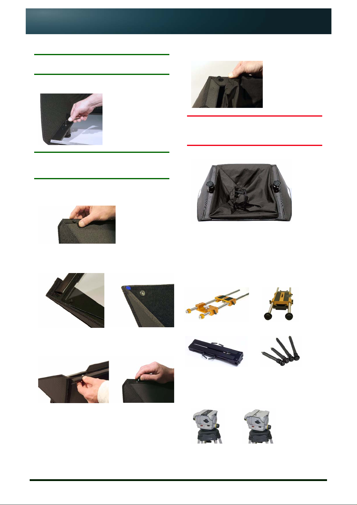
Locating pin
Pin hole
NOTE: Full assembly instructions for your specific On-Camera Unit can be found on the CD that accompanied the equipment or
from either of the web sites shown at the bottom of the page.
Introduction
All Autocue/QTV on-camera units (OCUs) comprise four components. An example is illustrated below:
1. Bracket (attaches to the
mounting plate to hold the
hood and monitor in front of
the camera)
3. Mounting Plate and
Telescopic Rods attach the
prompter to the tripod/
pedestal
All brackets attach to Autocue/QTV mounting plates using the same method.
All hoods and monitors are secured using common screw tube-clamps.
1. Hood and Glass Assembly
Autocue/QTV produces three sizes of hood and
glass: small, medium and large wide-angle.
3. Secure a side panel flap with four of the supplied M3
screws.
Repeat for the opposite flap.
NOTE: The medium hood requires fewer screws.
2. Hood and reflective glass
4. Monitor
NOTE: Small OCUs—which comprise a small wide-
angle hood, small bracket and 5-, 8- or 10-inch
monitor—are delivered pre-assembled.
Large and medium wide-angle hoods are delivered flatpacked and will require assembly.
1. Ensure that you have the required components:
- hood body
- glass panel
- glass retaining bar
- locking clamps
- screws
2. Open the side panels of the hood and fold the flaps over
the black metal frame.
Issue #: 080612 ©2003-2008 Autocue Group Ltd
www.qtv.com
4. Push the threaded pins of the lower Glass Retaining Strip
through the holes in the wide-angle hood frame and
secure in position with the supplied Screw Posts.
Ensure the retaining strip is on the inside of the hood as
illustrated.
5. Remove the large screw from a tube clamp and position
the clamp so that the locating pin aligns with the small
hole adjacent to the tube clamp screw hole in the metal
frame.
1
www.autocue.com
Page 2
On-Camera Unit Quick Assembly Instructions
Repeat for the second tube clamp.
NOTE: The locating pins ensure the holes in the tube
clamps are orientated correctly.
Use the supplied screws to secure the tube clamp in
position using a suitable Allen key.
NOTE: The tube-clamps of the medium wide-angle hood
are fixed in place using two screws for each
clamp.
6. Remove the upper Glass Retaining Strip by unfastening
the two thumb screws securing it to the top edge of the
hood.
Carefully stretch the elasticated end of the fabric light
baffle around the four screw posts on the rear of the
frame.
CAUTION: The glass plate is fragile. Take
great care when handling it and
the completed hood.
WIDE-ANGLE HOOD FULLY ASSEMBLED
7. Insert the shorter edge of the semi-reflective glass panel
into the lower Glass Retaining Strip.
Ensure the blue dot is on the side of the glass facing you.
8. Position the upper Glass Retaining Strip over the edge of
the glass panel and re-attach with the thumb screws that
were removed in step 6.
9. Place the assembled hood, glass panel face down, on a
solid, stable surface.
2. Mounting Plate Preparation
Autocue/QTV produces three standard mounting
plates to cover all camera/tripod cmbinations.
Telescopic rods are also available for large studio
lenses and pedestal configurations.
Gold Plate Pro Plate
Roller Plate Telescopic Rods
All three mounting plates connect to the tripod
head in the same way:
1. Remove the tripod camera plate.
Issue #: 080612 ©2003-2008 Autocue Group Ltd
www.qtv.com
2
www.autocue.com
Page 3

On-Camera Unit Quick Assembly Instructions
2. Attach the tripod camera plate to the base of your
mounting plate.
Attach the mounting plate to the tripod.All three
Telescopic rods are attached directly to the
pedestal head using the appropriate sockets.
3. Screw in the vertical hood mounting bars.
4. Loosen all the mounting bars slightly and align the
horizontal bars with the holes in the clamps of your
prompter display monitor and align the vertical bars with
the holes in the tube clamps attached to you hood.
5. Once positioned correctly, tighten all the mounting bars.
The Bracket Set is now ready to attach to the mounting
plate.
4. On-Camera Unit Assembly
Attach Bracket Set
3. Bracket Set Preparation
Autocue/QTV produces three sizes of Wide-Angle
Bracket Set: Medium, Small and Large.
NOTE: The vertical hood mounting bars are longer than
the horizontal prompter display unit mounting
bars.
A Bracket Set consists of a square, grooved length
of aluminium extrusion, horizontal prompter
display unit mounting bars, vertical hood mounting
bars and a one- or two-keyhole plate. All sizes are
put together in the same way.
1. Unscrew the keyhole plates in the bracket and rotate
them to the upright position.
NOTE: Ensure that the Mounting Plate is securely
attached to a tripod or shoulder mount.
1. Loosen the knurled locking rings on the adaptor rods at
the front of the Mounting Plate.
2. Place the openings in the keyhole plates over the ends of
the adaptor rods.
NOTE: Ensure the keyhole plates remain in front of the
locking rings.
3. Tighten the locking rings to secure the mounting bracket
in postion.
2. Screw in the horizontal prompter display unit mounting
bars.
Issue #: 080612 ©2003-2008 Autocue Group Ltd
www.qtv.com
Attach Wide Angle Hood
1. Slide the locking clamps of the Wide Angle Hood over the
vertical bars of the Mounting Bracket.
3
www.autocue.com
Page 4

On-Camera Unit Quick Assembly Instructions
2. Move the hood down the vertical bars to position the unit
so that the lens of your camera will be centred in the
glass plate of the hood.
3. Secure in the required position by tightening the locking
clamps on the rear of the hood.
Attach prompter display
1. Slide the horizontal rods of the Bracket Set into the
mounting holes in the prompter display chassis or the
tube clamps on the base of the unit.
2. Secure in the required position by tightening the locking
clamp on the side of the chassis or the tube clamp.
3. Repeat for the other clamp.
Adjust weight and balance
Adjust the position of the camera and the OCU on the
tripod so that the whole assembly is stable and that the
lens is positioned in the centre of the glass.
If required, counter-balance weights can be fitted.
5. Installing USB-Serial Converter
If you have purchased a USB To Serial Converter
supplied by Autocue, follow the steps outliend below to
install it.
The converter allows you to connect a serial scroll
controller to your computer using a standard USB port.
NOTE: Do NOT attach the USB-Serial Converter to your
computer before installing the drivers.
1. Place the mini-CD supplied with the converter into the
CD/DVD drive of your computer.
A web browser window will be displayed.
2. In the USB Version 1.1 section of the browser window,
locate the entry for the USB To Serial Cable (DB-9M)
FTDI Chip and click on Installation Driver.
3. Double-click the Win 98-XP Driver.exe and follow the on-
screen instructions.
4. When the drivers have been successfully installed,
remove the CD.
5. Plug the converter into a USB port on your computer and
use the Device Manager to see that the device has been
correctly identified as a serial port.
6. Note the number of the COM port that has been assigned
to the converter. This will be required when configuring
any scroll controller that is attached to the converter.
Connect cables
Plug the required video input and power cables into the
appropriate sockets on the display unit.
Further information
• If you require more detailed instructions please refer to the CD included in your shipment.
• Further help and guidance may be obtained from our web sites (URLs at the bottom of the
page) or contact Technical Support via email: support@autocue.com or support@qtv.com.
Issue #: 080612 ©2003-2008 Autocue Group Ltd
www.qtv.com
4
www.autocue.com
 Loading...