

Page 1

Table of Contents
1. Safety Precautions and Warnings........................................ 1
2. Product Information ............................................................. 2
2.1 Tool Description.......................................................... 2
2.2 Specifications............................................................... 3
2.3 Accessories................................................................... 3
2.4 Navigation Characters................................................ 3
2.5 Power............................................................................ 4
2.6 Product Setup .............................................................. 4
2.7 Vehicle Coverage......................................................... 8
3. Operating Instructions.......................................................... 9
3.1 Instructions for AUDI/SEAT/SKODA/VW.............. 9
3.2 Instructions for BMW .............................................. 15
3.3 Instructions for Land Rover .................................... 23
3.4 Instructions for Mercedes ........................................ 25
3.5 Instructions for Saab ................................................ 27
3.6 Instructions for Vauxhall ......................................... 28
3.7 Instructions for Volvo............................................... 29
4. Function List ........................................................................ 33
5. Warranty and Service ......................................................... 42
5.1 Limited One Year Warranty....................................... 42
5.2 Service Procedures ....................................................... 42
Page 2

1. Safety Precautions and Warnings
To prevent personal injury or damage to vehicles and/or the tool,
read this instruction manual first and observe the following safety
precautions at a minimum whenever working on a vehicle:
z Always perform automotive testing in a safe environment.
z Wear safety eye protection that meets ANSI standards.
z Keep clothing, hair, hands, tools, test equipment, etc, away from
all moving or hot engine parts.
z Operate the vehicle in a well-ventilated work area; Exhaust gases
are poisonous.
z Put blocks on drive wheels and never leave vehicle unattended
while running tests.
z Use extreme caution when working around the ignition coil,
distributor cap, ignition wires and spark plugs. These components
create hazardous voltages when the engine is running.
z Put transmission in PARK (for automatic transmission) or
NEUTRAL (for manual transmission) and make sure the parking
brake is engaged.
z Keep a fire extinguisher suitable for gasoline/chemical/ electrical
fires nearby.
z Don’t connect or disconnect any test equipment with ignition on
or engine running.
z Keep the tool dry, clean and free from oil, water and grease. Use a
mild detergent on a clean cloth to clean the outside of the tool,
when necessary.
z Do not soak the keypad as the keypad is not waterproof.
1
Page 3
2. Product Information
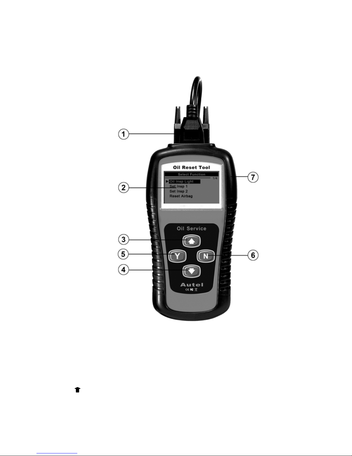
2.1 Tool Description
① EXTENSION CABLE -- Connects the tool to diagnostic
connector
② LCD DISPLAY -- Indicates test results. Backlit, 128 x 64 pixel
display with contrast adjustment.
③
UP SCROLL BUTTON -- Moves up through menu and
submenu items in menu mode.
2
Page 4

④ DOWN SCROLL BUTTON -- Moves down through menu
and submenu items in menu mode.
⑤ Y BUTTON -- Confirms a selection (or action) from a menu, and
enters main menu when pressed from home screen.
⑥ N BUTTON -- Cancels a selection (or action) from a menu or
returns to previous menu. It is also used to set up the unit when
pressed from home screen.
⑦ RUBBER BOOT -- Protects the tool from drop, abrasion and etc.
2.2 Specifications
1) Display: Backlit, 128 x 64 pixel display with contrast adjustment
2) Operating Temperature: 0 to 50°C (32 to 122 F°)
3) Storage Temperature: -20 to 70°C (-4 to 158 F°)
4) External Power: 8.0 to 18.0 Volts provided via vehicle battery
5) Dimensions:
Length Width Height
178 mm (7.00”) 95 mm (3.75”) 34 mm (1.35”)
6) NW: 0.70kg (1.54lb), GW: 1.00kg(2.20lb)
2.3 Accessories
1) User’s manual -- Instructions on tool operations
2) Extension cable -- Connects the tool to diagnostic connector.
3) OBDII&OBDI connectors -- Provide power to the tool and
communicate between the tool and vehicle.
4) USB cable -- Used to upgrade the tool.
5) CD -- Contains update tool, USB driver and etc.
6) Plastic case -- Used to store the tool and accessories.
2.4 Navigation Characters
Characters used to help navigate the tool are:
1) “►” -- Indicates current selection.
3
Page 5

2) “x/x” -- Indicates the total number of items under a menu and the
sequence of currently selected item.
3) “ ”-- indicates additional information is available on next screen(s).
4) “ ”-- indicates additional information is available on previous
screen(s).
2.5 Power
The tool is directly powered up through the vehicle Data Link
Connector (DLC) except VOLVO (A/B connectors) which need an
external 12V power source. Follow the steps below to turn on the tool:
1) Connect the extension cable to connector and to the tool.
2) Find DLC on vehicle.
z A plastic DLC cover may be found for some vehicles and you
need to remove it before plugging the OBD2 cable.
3) Plug diagnostic connector to the vehicle’s DLC.
4) Turn ignition on.
2.6 Product Setup
The tool allows you to make the following adjustments and settings:
1) Language: Selects desired language. The device supports English
by default.
2) Contrast Adjustment: Adjusts the contrast of the LCD display.
3) Display Test: Checks the LCD display is working properly.
4) Keyboard Test: Checks if the the keyboard is working properly. .
5) Information: Views software and hardware information of the
tool and etc.
To enter the setup menu mode
Press N button from home screen to enter System Setup menu. Follow
the instructions to make adjustments and settings as described in the
following setup options.
4
Page 6

System Setup
1/5
►Language
Contrast
Display Test
Keyboard Test
Information
Language
1) From System Setup menu, use UP/DOWN scroll button to select
Language, and press the Y button.
System Setup
1/5
►Language
Contrast
Display Test
Keyboard Test
Information
2) Use UP/DOWN button to select desired language and press Y
button to confirm and return to previous menu.
Language Set
1/1
►English
Contrast
1) From System Setup menu, use UP/DOWN scroll button to select
Contrast, and press the Y button.
5
Page 7
System Setup
2/5
Language
►Contrast
Display Test
Keyboard Test
Information
2) From Contrast menu, use the UP/DOWN scroll buttons to
increase or decrease the contrast.
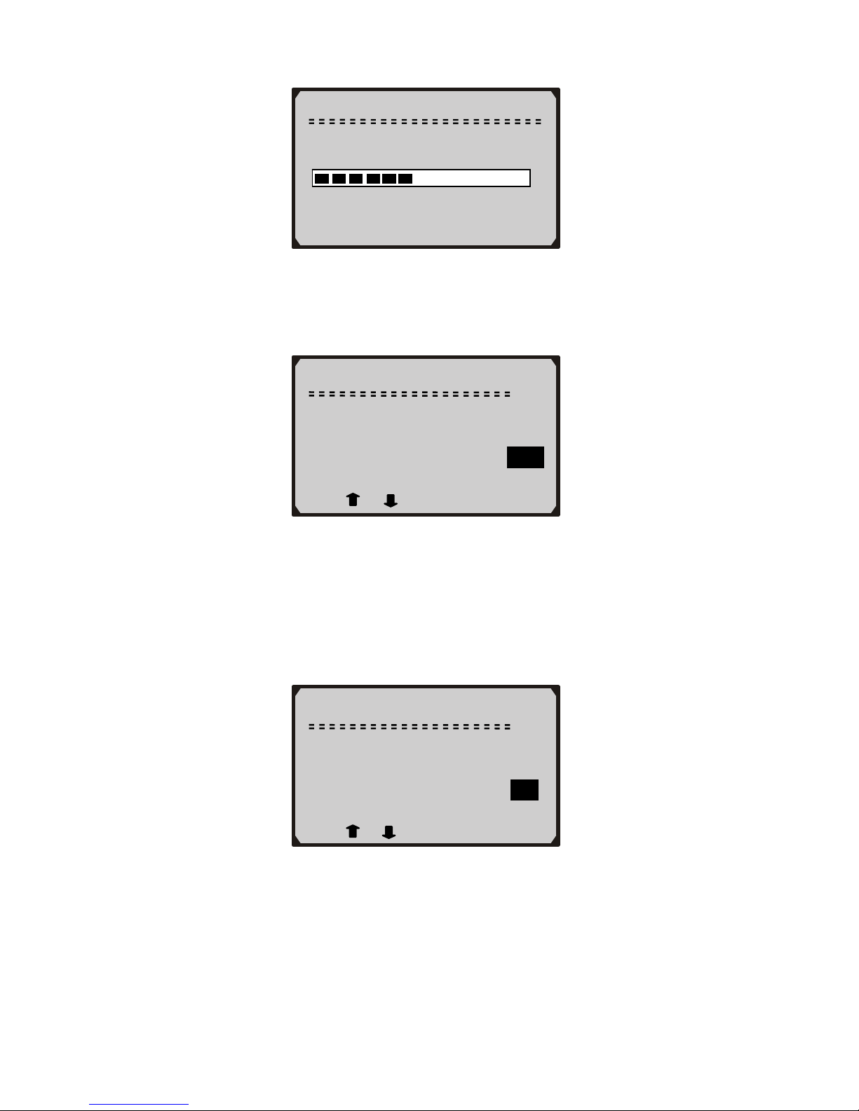
Contrast
(35%)
Use
or to change
3) Press the Y button to save the adjustment and return to previous
menu; or press the N button to return to previous menus without
saving.
Display Test
1) From System Setup menu, use UP/DOWN scroll button to select
Display Test and press the Y button.
System Setup
3/5
Language
Contrast
►Display Test
Keyboard Test
Information
6
Page 8
2) Press Y button again to start test. Look for missing spots in the
solid black characters.
Display Test
Press [Y] to test.
Look for missing
Spots in characters.
Press <N> to return.
3) When completed, press the N button to return.
Keyboard Test
1) Use UP/DOWN scroll buttons to select Keyboard Test from
System Setup menu, and then press Y button.
System Setup
4/5
Language
Contrast
Display Test
►Keyboard Test
Information
2) Press any key to start test. When you press a key, the key name
should be observed on the display. If the name does not show up,
then the key is not working properly.
Keyboard Test
Press any key to
start
Key:
Double [N] to Return
3) Double press N to return to the previous menu.
7
Page 9

Tool Information
1) Use UP/DOWN scroll buttons to select Information from
System Setup menu, and then press Y button.
System Setup
5/5
Language
Contrast
Display Test
Keyboard Test
►Information
2) View tool information on screen.
Information
Serial No. : 56174842
Burn Date: 28/10/2008
S/W Ver : V1.02
H/W Ver : V1.50
LIB Ver : V1.20
2.7 Vehicle Coverage
The Oil Light and Airbag Reset Tool is specially designed to reset oil
service light, oil inspection light, service mileage, service intervals and
airbag on most major Asian, American and European vehicles.
Compatible vehicles are as follows:
Acura, Audi, BMW, Buick, Cadillac, Chevrolet, Chevrolet/GMC,
Chrysler, Ford/Mercury/Lincoln, Honda, Isuzu, Jeep, Land Rover,
Mercedes, Nissan/Infiniti, Oldsmobile, Pontiac, Saab, Saturn, Scion,
Seat, Skoda, Toyota/Lexus, Vauxhall, Volvo, VW.
For OBDI vehicles please use proper connectors included in this tool
kit to do the service work.
8
Page 10

3. Operating Instructions
IMPORTANT: This section of the manual offers
instructions on how to use the tool to reset oil/service light
and airbags electronically ONLY. Please power on the unit
to view manual reset instructions for those vehicles that
need to do the service job manually.
All software screens shown in this manual are examples,
actual test screens may vary for each vehicle being tested.
Observe the menu titles and onscreen instructions to make
correct option selections.
3.1 Instructions for AUDI/SEAT/SKODA/VW
1) Turn the ignition off.
2) Locate the vehicle’s Data Link Connector (DLC).
3) Plug proper connector to the vehicle’s DLC.
4) Turn the ignition on. But do not start the engine.
5) Press the Y button from home screen.
6) Use UP/DOWN scroll button to select vehicle make, and press Y
button to confirm.
Select Vehicle Make
1/26
► Audi
BMW
Land Rover
Mercedes
Saab
Seat
A. Automatic Vehicle Detect
The Auto Detect is used to detect vehicle and available functions
automatically.
1) Use UP/DOWN scroll button to select Auto Detect, and press Y
button.
9
Page 11

2) Wait a few seconds till the following screen shows.
Select Vehicle Model
1/26
► Auto Detect
A2 (Up to 98)
A2 (As of 98)
A3 (Up to 98)
A3 (As of 98)
A4 (Up to 98)
Select Oil Type
1/3
►Fixed Service
Flexible-Gasoline
Flexible-Diesel
z If the tool fails to communicate with the vehicle, a “LINK
ERROR!” message shows up on the display.
9 Verify that the ignition is ON;
9 Check if the tool’s connector is securely connected to the
vehicle’s DLC;
9 Turn the ignition off and wait for about 10 seconds. Turn the
ignition back to on.
z If the “LINK ERROR” message does not go away, then there
might be problems for the tool to communicate with the
vehicle. Contact yo ur local distributor or the manufa cturer’s
customer service department for assistance.
3) Use UP/DOWN button to select function and press Y button.
10
Page 12
Select Function
1/3
► Oil Insp. Light
Set Insp. 1
Set Insp. 2
z Different vehicle supports different functions, so the displayed
functions vary from one vehicle to another.
4) Select the function that your vehicle supports and press Y button.
Wait a few seconds while the tool is performing service resetting.
Oil Insp. Light
Service setting…
-Please Wait-
5) A message “RESET OK!” comes up, indicating oil service reset is
completed.
Oil Insp. Light
RESET OK!
Press any key to cont.
6) If the service can not be performed automatically, following
screen shows..
11
Page 13
Manual
Reading Channel Data…
-Please Wait28
7) Wait a few seconds till following screen shows and use
UP/DOWN button to change value.
Min Mil. to Service
1/3
Channel No 42 (Mil)
Current Value 9000
Set Value 9000
[N] = Next, [Y] = Set/Exit
Use or to change
z x/x to the upper right part of the screen indicates total number
of supported service channels and the sequence of current
channel.
8) Use N button to move to next setup screen.
Mil. Since Service
2/3
Channel No 40 (Mil)
Current Value 700
Set Value 700
[N] = Next, [Y] = Set/Exit
Use or to change
z Different vehicle supports different oil service channels, so
retrieved channel numbers vary from one vehicle to another.
Normally, a vehicle supports 1-5 channels.
z “Current Value” is the value of the most recent setup
retrieved by the tool. If you change your mind after making
12
Page 14

new setups, it can be used to reset all changed values to the
original ones. Write down this value before making any
changes.
9) Use UP/DOWN scroll button to select Save and press Y button to
save your settings.
z If you want to continue to set values, use UP/DOWN scroll
button to select Back and press Y button to return to continue
setup. If you want to cancel all setups, use UP/DOWN scroll
button to select Exit and press Y button, or simply press N
button to exit.
10) Wait a few seconds till the “RESET OK!” message comes up.
Press any key to return.
Manual
RESET OK!
Press any key to con.
Manual
Back Save Exit
[Back] = Cont. to Set
[Save] = Save Setup
[Exit] = Cancel Setup
z If a “LINK ERROR!” message shows up on the display,
please follow on-screen instructions to troubleshoot it.
B. Manual Vehicle Selection
1) If you want to select vehicle manually, use UP/DOWN scroll
button to select vehicle model year and press Y button.
13
Page 15

Select Vehicle Model
2/26
Auto Detect
►A2 (Up to 98)
A2 (As of 98)
A3 (Up to 98)
A3 (As of 98)
A4 (Up to 98)
2) Use UP/DOWN scroll button to select the function that your
vehicle supports.
3) Wait a few seconds till the following screen appears.
Select Function
1/4
► Oil Insp. Light
Set Insp. 1
Set Insp. 2
Reset Airbag
Oil Insp. Light
RESET OK!
Press any key to con.
4) If a the service can not be performed automatically, following
screen shows:
14
Page 16

Oil Insp. Light
Service Reset failed!
Please try others.
Press any key to con.
z If the airbags can not be reset automatically, a “LINK
ERROR!” message comes up and you can not reset them
manually. Follow on-screen instructions to trouble shoot it.
5) Press any key to continue to perform setup manually.
Manual
Reading Channel Data…
-Please Wait28
6) Wait a few seconds till following screen shows:
Min Mil. to Service
1/3
Channel No 42 (Mil)
Current Value 9000
Set Value 9000
[N] = Next, [Y] = Set/Exit
Use or to change
7) Repeat Step 7-10 on Page 12-13 to perform the setup.
3.2 Instructions for BMW
1) Turn the ignition off.
2) Locate the vehicle’s Data Link Connector (DLC).
3) Plug proper connector to the vehicle’s DLC.
15
Page 17

4) Turn the ignition on. But do not start the engine.
5) Press the Y button from home screen.
6) Use UP/DOWN scroll button to select BMW, and press Y button
to confirm.
Select Vehicle Make
3/26
Audi
►BMW
Land Rover
Mercedes
Saab
Seat
7) Use UP/DOWN scroll button to select proper adapter, and press Y
button to confirm.
Select Adapter
1/2
►OBDII-16PIN
OBDI-20PIN
OBDII-16PIN Connector
BMW vehicles with OBDII connector have more service functions than
those with 20 PIN connector. For E38-7 Series, E39-5 Series, E46-3
Series, E52-Z8, E53-X5, E70-X5, E85-Z4, R50-Mini, R52-Mini, R53Mini and R56-Mini models, please see instructions below to do the
service settings.
1) Use UP/DOWN scroll button to select the vehicle model under
test, and press Y button to confirm.
16
Page 18

Select Vehicle Model
3/23
E38-7 Series
E39-5 Series
►E46-3 Series
E52-Z8
E53-X5
E60- 5Series
2) Use UP/DOWN scroll button to select function, and press Y
button to confirm.
Select Function
1/3
►Oil Service
Inspection
Time
3) Wait a few seconds till a “RESET OK!” message shows on the
screen.
Oil Service
RESET OK!
Press any key to con.
z If a “LINK ERROR!” message shows up on the display,
please follow on-screen instructions to troubleshoot it.
For E60-5 Series, E61-5 Series, E63-6 Series, E64-6 Series, E65-7
Series, E83-X3, E86-Z4, E87-1 Series, E90-3 Series, E91-3 Series,
E92-3 Series, and E93-3 Series models, please see instructions below to
do the service settings.
1) Use UP/DOWN scroll button to select the vehicle model under
test, and press Y button to confirm.
17
Page 19

Select Vehicle Model
9/23
E61-5 Series
E63-6 Series
►E64-6 Series
E65-7 Series
E70-X5
E83-X3
2) Use UP/DOWN scroll button to select oil type, and press Y button
to confirm.
Select Function
1/2
►Benzine
Diesel
3) If you wish to do the setting automatically, use UP/DOWN scroll
button to select Reset, and press Y button to confirm.
Benzine
1/2
►Reset
Set
4) Use UP/DOWN scroll button to select function, and press Y
button to confirm.
18
Page 20

Select Function
1/7
►Vehicle Check
Oil Service
Front Brake
Rear Brake
Brake Fluid
Micro Filter
5) Wait a few seconds till a “RESET OK!” message shows on the
screen.
Vehicle Chec
k
RESET OK!
Press any key to con.
z If a “LINK ERROR!” message shows up on the display,
please follow on-screen instructions to troubleshoot it.
6) If you wish to change the service life percentage manually, use
UP/DOWN scroll button to select Set, and press Y button to
confirm.
Benzine
2/2
Reset
►Set
7) Use UP/DOWN scroll button to select function, and press Y
button to confirm.
19
Page 21

Select Function
3/7
Vehicle Check
Oil Service
►Front Brake
Rear Brake
Brake Fluid
Micro Filter
8) Use UP/DOWN scroll button to change value and press Y button
to confirm.
Front Brake
Input Current Life
90 %
Use or to change
9) Wait a few seconds till a “RESET OK!” message shows on the
screen.
Front Brake
RESET OK!
Press any key to con.
z If a “LINK ERROR!” message shows up on the display,
please follow on-screen instructions to troubleshoot it.
OBDI-20PIN Connector
1) Use UP/DOWN scroll button to select the vehicle model under
test, and press Y button to confirm.
20
Page 22

Select Vehicle Model
3/7
E36
E38
►E39
E46
E60
E64
2) Use UP/DOWN scroll button to select function, and press Y
button to confirm.
Select Function
2/2
Oil Service
►Inspection
3) Wait a few seconds till a “RESET OK!” message shows on the
screen.
Inspection
RESET OK!
Press any key to con.
z If a “LINK ERROR!” message shows up on the display,
please follow on-screen instructions to troubleshoot it.
4) If the vehicle under test is not listed, use UP/DOWN scroll button
to select Others, and press Y button to confirm.
21
Page 23

Select Vehicle Model
7/7
►Others
5) Use UP/DOWN scroll button to select a mode, and press Y button
to confirm.
Others
1/2
►Mode 1
Mode 2
6) Use UP/DOWN scroll button to select function, and press Y
button to confirm.
Select Function
2/2
Oil Service
►Inspection
7) Wait a few seconds till a “RESET OK!” message shows on the
screen.
22
Page 24

Inspection
RESET OK!
Press any key to con.
z If a “LINK ERROR!” message shows up on the display,
please follow on-screen instructions to troubleshoot it.
3.3 Instructions for Land Rover
1) Turn the ignition off.
2) Locate the vehicle’s Data Link Connector (DLC).
3) Plug proper connector to the vehicle’s DLC.
4) Turn the ignition on. But do not start the engine.
5) Press the Y button from home screen.
6) Use UP/DOWN scroll button to select Land Rover, and press Y
button to confirm.
Select Vehicle Make
4/26
Audi
BMW
►Land Rover
Mercedes
Saab
Seat
7) Use UP/DOWN scroll button to select vehicle model, and press Y
button to confirm.
23
Page 25

Select Vehicle Model
4/4
Defender
Discovery
Range Rover
►R75
z ONLY R75 needs to do oil service and inspection work with
this tool.
8) Use UP/DOWN scroll button to select a function, and press Y
button to confirm.
R75
3/3
Oil Service
Inspection
►Time
9) Wait a few seconds till a “RESET OK!” message shows on the
screen.
Time
RESET OK!
Press any key to cont.
z If a “LINK ERROR!” message shows up on the display,
please follow on-screen instructions to troubleshoot it.
24
Page 26

3.4 Instructions for Mercedes
1) Turn the ignition off.
2) Locate the vehicle’s Data Link Connector (DLC).
3) Plug proper connector to the vehicle’s DLC.
4) Turn the ignition on. But do not start the engine.
5) Press the Y button from home screen.
6) Use UP/DOWN scroll button to select Mercedes, and press Y
button to confirm.
Select Vehicle Make
2/26
Audi
►Mercedes
BMW
Land Rover
Saab
Seat
7) Observe the menu title and use UP/DOWN scroll button to do a
series of menu selections to identify the vehicle under test, and
press Y button to confirm.
E Class
1/4
►1996
1997-2000
2001-2002
2003
8) Press Y button to do the service job.
25
Page 27

E Class
1/1
►Oil Service
z You can do the service job automatically or do manual reset on
some Mercedes vehicles, so the menu items are shown as
below:
SLK Class
1/2
►Oil Service
Manual Reset
9) Wait a few seconds till a “RESET OK!” message shows on the
screen.
Oil Service
RESET OK!
Press any key to con.
z If a “LINK ERROR!” message shows up on the display,
please follow on-screen instructions to troubleshoot it.
Note: Instrument cluster on some vehicles will turn off power and
then turn on power again while resetting the service interval
mileage.
26
Page 28

3.5 Instructions for Saab
1) Turn the ignition off.
2) Locate the vehicle’s Data Link Connector (DLC).
3) Plug proper connector to the vehicle’s DLC.
4) Turn the ignition on. But do not start the engine.
5) Press the Y button from home screen.
6) Use UP/DOWN scroll button to select Saab, and press Y button
to confirm.
Select Vehicle Make
5/26
Audi
BMW
Land Rover
Mercedes
► Saab
Seat
7) Use UP/DOWN scroll button to select Auto Detect to detect
vehicle that need to use this device to perform service setting, and
press Y button to confirm.
Select Vehicle Model
5/5
9-3
9-5
900 Series
All Models
►Auto Detect
8) Wait a few seconds till a “RESET OK!” message shows on the
screen.
27
Page 29

Oil Service
RESET OK!
Press any key to con.
z If a “LINK ERROR!” message shows up on the display,
please follow on-screen instructions to troubleshoot it.
3.6 Instructions for Vauxhall
1) Turn the ignition off.
2) Locate the vehicle’s Data Link Connector (DLC).
3) Plug proper connector to the vehicle’s DLC.
4) Turn the ignition on. But do not start the engine.
5) Press the Y button from home screen.
6) Use UP/DOWN scroll button to select Vauxhall, and press Y
button to confirm.
Select Vehicle Make
8/26
Skoda
►Vauxhall
Volvo
VW
Acura
Buick
7) Use UP/DOWN scroll button to select a vehicle you wish to work
with, and press Y button to confirm.
28
Page 30

Select Vehicle Model
1/5
►Agila
Vectra
Astra G
Corsa C
Others
z If your vehicle is not listed in the menu, please select Others.
8) Press Y button to start performing oil service.
Agila
1/1
►Oil Service
9) Wait a few seconds till a “RESET OK!” message shows on the
screen.
Oil Service
RESET OK!
Press any key to cont.
z If a “LINK ERROR!” message shows up on the display,
please follow on-screen instructions to troubleshoot it.
3.7 Instructions for Volvo
1) Turn the ignition off.
2) Locate the vehicle’s Data Link Connector (DLC).
3) Plug proper connector to the vehicle’s DLC.
29
Page 31

4) Turn the ignition on. But do not start the engine.
5) Press the Y button from home screen.
6) Use UP/DOWN scroll button to select Volvo, and press Y button
to confirm.
7) Use UP/DOWN scroll button to select a vehicle you wish to work
with, and press Y button to confirm.
Select Vehicle Make
9/26
Skoda
Vauxhall
►Volvo
VW
Acura
Buick
Select Vehicle Model
1/20
►Volvo V70
Volvo V40
Volvo 850
Volvo 850TDI
240
740
8) Use UP/DOWN button to select a function and press Y button to
confirm.
Volvo V70
1/3
►Service
Airbag
Manual Reset
z For vehicles that can not be reset manually, the screen shows
as follows:
30
Page 32

Volvo 850TDI
1/2
►Service
Airbag
9) Wait a few seconds till a “RESET OK!” message shows on the
screen.
Service
RESET OK!
Press any key to cont.
z If a “LINK ERROR!” message shows up on the display,
please follow on-screen instructions to troubleshoot it.
10) If your vehicle is not listed in the menu, please select Others.
Select Vehicle Model
20/20
XC90
►Others
11) Use UP/DOWN button to select a mode and press Y button to
confirm.
31
Page 33

12) Use UP/DOWN button to select the connector your vehicle uses
to start service setting.
Others
1/2
►Mode 1
Mode 2
Mode1
1/2
►AB Connector
OBDII-Connector
13) Wait a few seconds till a “RESET OK!” message shows on the
screen.
AB Connecto
r
RESET OK!
Press any key to cont.
z If a “LINK ERROR!” message shows up on the display,
please follow on-screen instructions to troubleshoot it.
32
Page 34

4. Function List
Manufacturer Model Year Functions
AUDI A2
● Reset Oil Inspection Light
● Set Inspection 1 Service Interval
● Set Inspection 2 Service Interval
● Reset Airbag
AUDI A100 1991-1994
● Reset Oil Inspection Light
● Set Inspection 1 Service Interval
● Set Inspection 2 Service Interval
● Reset Airbag
AUDI A3
● Reset Oil Inspection Light
● Set Inspection 1 Service Interval
● Set Inspection 2 Service Interval
● Reset Airbag
AUDI A3 from D06
● Reset Oil Inspection Light
● Set Inspection 1 Service Interval
● Set Inspection 2 Service Interval
● Reset Airbag
AUDI A4 1996-1997
● Reset Oil Inspection Light
● Set Inspection 1 Service Interval
● Set Inspection 2 Service Interval
● Reset Airbag
AUDI A4 1998-2004
● Reset Oil Inspection Light
● Set Inspection 1 Service Interval
● Set Inspection 2 Service Interval
● Reset Airbag
AUDI
A4 with
D00/1
● Reset Oil Inspection Light
● Set Inspection 1 Service Interval
● Set Inspection 2 Service Interval
● Reset Airbag
AUDI A6 1995-1997
● Reset Oil Inspection Light
● Set Inspection 1 Service Interval
● Set Inspection 2 Service Interval
● Reset Airbag
33
Page 35

Manufacturer Model Year Functions
AUDI A6 1998-2004
● Reset Oil Inspection Light
● Set Inspection 1 Service Interval
● Set Inspection 2 Service Interval
● Reset Airbag
AUDI
A6 with
D00/1
● Reset Oil Inspection Light
● Set Inspection 1 Service Interval
● Set Inspection 2 Service Interval
● Reset Airbag
AUDI A8 1997-2005
● Reset Oil Inspection Light
● Set Inspection 1 Service Interval
● Set Inspection 2 Service Interval
● Reset Airbag
AUDI A8 until D07 1997-2005
● Reset Oil Inspection Light
● Set Inspection 1 Service Interval
● Set Inspection 2 Service Interval
● Reset Airbag
AUDI TT 2000-2004
● Reset Oil Service Light
● Reset Airbag
BMW E36 (OBDI) 1996-2003
● Reset Oil Service Light
● Set Inspection Mileage
BMW E38 (OBDI) 1988-2001
● Reset Oil Service Light
● Set Inspection Mileage
BMW E39 (OBDI) 1988-2000
● Reset Oil Service Light
● Set Inspection Mileage
BMW E46 (OBDI)
● Reset Oil Service Light
● Set Inspection Mileage
BMW Others(OBDI) 1991-1997
● Reset Oil Service Light
● Set Inspection Mileage
34
Page 36

Manufacturer Model Year Functions
BMW
E38-7 Series
(OBDII)
● Reset Oil Service Light
● Set Inspection Mileage
● Time
BMW
E39-5 Series
(OBDII)
● Reset Oil Service Light
● Set Inspection Mileage
● Time
BMW
E46-3 Series
(OBDII)
● Reset Oil Service Light
● Set Inspection Mileage
● Time
BMW
E52-Z8
(OBDII)
● Reset Oil Service Light
● Set Inspection Mileage
● Time
BMW
E53-X5
(OBDII)
● Reset Oil Service Light
● Set Inspection Mileage
● Time
BMW
E60-5 Series
(OBDII)
● Vehicle Check
● Oil Service
● Front Brake
● Rear Brake
● Brake Fluid
● Micro Filter
● Spark Plus
BMW
E61-5 Series
(OBDII)
● Vehicle Check
● Oil Service
● Front Brake
● Rear Brake
● Brake Fluid
● Micro Filter
● Spark Plus
BMW
E63-6 Series
(OBDII)
● Vehicle Check
● Oil Service
● Front Brake
● Rear Brake
● Brake Fluid
● Micro Filter
● Spark Plus
35
Page 37

Manufacturer Model Year Functions
BMW
E64-6 Series
(OBDII)
● Vehicle Check
● Oil Service
● Front Brake
● Rear Brake
● Brake Fluid
● Micro Filter
● Spark Plus
BMW
E65-7 Series
(OBDII)
● Vehicle Check
● Oil Service
● Front Brake
● Rear Brake
● Brake Fluid
● Micro Filter
● Spark Plus
BMW
E70-X5
(OBDII)
● Reset Oil Service Light
● Set Inspection Mileage
● Time
BMW
E80-X3
(OBDII)
● Vehicle Check
● Oil Service
● Front Brake
● Rear Brake
● Brake Fluid
● Micro Filter
● Spark Plus
BMW
E85-Z4
(OBDII)
● Reset Oil Service Light
● Set Inspection Mileage
● Time
BMW
E86-Z4
(OBDII)
● Vehicle Check
● Oil Service
● Front Brake
● Rear Brake
● Brake Fluid
● Micro Filter
● Spark Plus
36
Page 38

Manufacturer Model Year Functions
BMW
E87-1 Series
(OBDII)
● Vehicle Check
● Oil Service
● Front Brake
● Rear Brake
● Brake Fluid
● Micro Filter
● Spark Plus
BMW
E90-3 Series
(OBDII)
● Vehicle Check
● Oil Service
● Front Brake
● Rear Brake
● Brake Fluid
● Micro Filter
● Spark Plus
BMW
E91-3 Series
(OBDII)
● Vehicle Check
● Oil Service
● Front Brake
● Rear Brake
● Brake Fluid
● Micro Filter
● Spark Plus
BMW
E92-3 Series
(OBDII)
● Vehicle Check
● Oil Service
● Front Brake
● Rear Brake
● Brake Fluid
● Micro Filter
● Spark Plus
BMW
E93-3 Series
(OBDII)
● Vehicle Check
● Oil Service
● Front Brake
● Rear Brake
● Brake Fluid
● Micro Filter
● Spark Plus
37
Page 39

Manufacturer Model Year Functions
BMW R50-Mini
● Reset Oil Service Light
● Set Inspection Mileage
● Time
BMW R52-Mini
● Reset Oil Service Light
● Set Inspection Mileage
● Time
BMW R53-Mini
● Reset Oil Service Light
● Set Inspection Mileage
● Time
BMW R56-Mini
● Reset Oil Service Light
● Set Inspection Mileage
● Time
Land Rover R75
● Reset Oil Service Light
● Set Inspection Mileage
● Time
Mercedes A class ● Reset Oil Service Light
Mercedes C class 1997-2000 ● Reset Oil Service Light
Mercedes E class 1996-2002 ● Reset Oil Service Light
SLK class 1996-2001 ● Reset Oil Service Light
Mercedes CLK class 1997-2003
● Reset Oil Service Light
● Reset Airbag
Mercedes Sprinter ● Reset Oil Service Light
Mercedes Others 1997-2002 ● Reset Oil Service Light
Seat Alhambra
● Reset Oil Inspection Light
● Set Inspection 1 Service Interval
● Set Inspection 2 Service Interval
● Reset Airbag
38
Page 40

Manufacturer Model Year Functions
Seat Alhambra 98
● Reset Oil Inspection Light
● Set Inspection 1 Service Interval
● Set Inspection 2 Service Interval
● Reset Airbag
Seat Arosa
● Reset Oil Service Light
● Reset Airbag
Seat Leon
● Reset Oil Service Light
● Reset Airbag
Seat Toledo
● Reset Oil Service Light
● Reset Airbag
Skoda Fabia
● Reset Oil Inspection Light
● Set Inspection 1 Service Interval
● Set Inspection 2 Service Interval
● Reset Airbag
Skoda Octavia
● Reset Oil Inspection Light
● Set Inspection 1 Service Interval
● Set Inspection 2 Service Interval
● Reset Airbag
Skoda Octavia 98
● Reset Oil Inspection Light
● Set Inspection 1 Service Interval
● Set Inspection 2 Service Interval
● Reset Airbag
Vauxhall Agila ● Reset Oil Inspection Light
Vauxhall Vectra ● Reset Oil Inspection Light
Vauxhall Astra G ● Reset Oil Inspection Light
Vauxhall Corsa C ● Reset Oil Inspection Light
39
Page 41

Manufacturer Model Year Functions
Volvo V70 1998
● Reset Oil Service Light
● Reset Airbag
Volvo V40
● Reset Oil Service Light
● Reset Airbag
Volvo 850 1996-1997
● Reset Oil Service Light
● Reset Airbag
Volvo 850 tdi
● Reset Oil Service Light
● Reset Airbag
VW Golf 3 1993-1999
● Reset Oil Inspection Light
● Set Inspection 1 Service Interval
● Set Inspection 2 Service Interval
● Reset Airbag
VW Golf 4 1993-1999
● Reset Oil Inspection Light
● Set Inspection 1 Service Interval
● Set Inspection 2 Service Interval
● Reset Airbag
VW New Beetle 1998-2001
● Reset Oil Inspection Light
● Set Inspection 1 Service Interval
● Set Inspection 2 Service Interval
● Reset Airbag
VW Passat 1991-2001
● Reset Oil Inspection Light
● Set Inspection 1 Service Interval
● Set Inspection 2 Service Interval
● Reset Airbag
VW Passat B5
● Reset Oil Inspection Light
● Set Inspection 1 Service Interval
● Set Inspection 2 Service Interval
● Reset Airbag
40
Page 42

Manufacturer Model Year Functions
VW Passat 97 1991-2001
● Reset Oil Inspection Light
● Set Inspection 1 Service Interval
● Set Inspection 2 Service Interval
● Reset Airbag
VW Polo 98
● Reset Oil Inspection Light
● Set Inspection 1 Service Interval
● Set Inspection 2 Service Interval
● Reset Airbag
VW Sharan
● Reset Oil Inspection Light
● Set Inspection 1 Service Interval
● Set Inspection 2 Service Interval
● Reset Airbag
VW Sharan 98
● Reset Oil Inspection Light
● Set Inspection 1 Service Interval
● Set Inspection 2 Service Interval
VW Lupo
● Reset Oil Inspection Light
● Set Inspection 1 Service Interval
● Set Inspection 2 Service Interval
● Reset Airbag
VW Bora
● Reset Oil Inspection Light
● Set Inspection 1 Service Interval
● Set Inspection 2 Service Interval
● Reset Airbag
VW
Transporter
T4
● Reset Oil Inspection Light
● Set Inspection 1 Service Interval
● Set Inspection 2 Service Interval
● Reset Airbag
VW Eurovan 1999-2001 Auto detect
VW Jetta 1993-1999 Auto detect
41
Page 43

5. Warranty and Service
5.1 Limited One Year Warranty
Autel warrants to its customers that this product will be free from all
defects in materials and workmanship for a period of one (1) year from
the date of the original purchase, subject to the following terms and
conditions:
1) The sole responsibility of Autel under the Warranty is limited to
either the repair or, at the option of Autel, replacement of the tool
at no charge with Proof of Purchase. The sales receipt may be used
for this purpose.
2) This warranty does not apply to damages caused by improper use,
accident, flood, lightning, or if the product was altered or repaired
by anyone other than the Manufacturer’s Service Center.
3) Autel shall not be liable for any incidental or consequential
damages arising from the use, misuse, or mounting of the tool.
Some states do not allow limitations on how long an implied
warranty lasts, so the above limitations may not apply to you.
4) All information in this manual is based on the latest information
available at the time of publication and no warranty can be made
for its accuracy or completeness. Autel reserves the right to make
changes at any time without notice.
5.2 Service Procedures
If you have any questions, please contact your local store, distributor or
visit our website at www.auteltech.com.
If it becomes necessary to return the tool for repair, contact your local
distributor for more information.
42
 Loading...