

Page 1

Table of Contents
1. SAFETY PRECAUTIONS AND WARNINGS .............................................. 1
2. GENERAL INFORMATION .......................................................................... 2
2.1 ON-BOARD DIAGNOSTICS (OBD) II ............................................................. 2
2.2 OIL/SERVICE RESET ..................................................................................... 2
2.3 EPB ............................................................................................................... 2
2.4 TPMS SYSTEM REVIEW ................................................................................ 3
2.5 ABS AND SRS SYSTEMS ................................................................................ 3
2.6 SAS REVIEW.................................................................................................. 4
2.7 DPF REVIEW ................................................................................................. 5
3. USING THE SCAN TOOL .............................................................................. 7
3.1 TOOL DESCRIPTION ...................................................................................... 7
3.2 SPECIFICATIONS ............................................................................................ 9
3.3 ACCESSORIES INCLUDED............................................................................... 9
3.4 KEYBOARD .................................................................................................... 9
3.5 POWER .......................................................................................................... 9
3.6 SYSTEM SETUP ............................................................................................ 10
3.7 VEHICLE COVERAGE .................................................................................. 14
3.8 PRODUCT TROUBLESHOOTING.................................................................... 16
4. PLAYBACK DATA ....................................................................................... 17
4.1 REVIEWING DATA ....................................................................................... 17
4.2 DELETING DATA ......................................................................................... 18
4.3 PRINTING DATA .......................................................................................... 18
5. OBDII DIAGNOSTICS ................................................................................. 19
5.1. READ CODES ............................................................................................... 20
5.2. ERASING CODES .......................................................................................... 23
5.3. LIVE DATA .................................................................................................. 24
5.4. FREEZE FRAME ........................................................................................... 30
5.5. RETRIEVING I/M READINESS STATUS ......................................................... 31
5.6. O2 MONITOR TEST ..................................................................................... 34
5.7. ON-BOARD MONITOR TEST ........................................................................ 36
5.8. COMPONENT TEST ...................................................................................... 39
5.9. VIEWING VEHICLE INFORMATION .............................................................. 41
Page 2

5.10. MODULES PRESENT .................................................................................... 42
5.11. DTC LOOKUP ............................................................................................. 43
6. TPMS (TIRE PRESSURE MONITOR SYSTEM) ...................................... 45
6.1. ENTER THE VEHICLE INFORMATION ........................................................... 45
6.2. TPMS DIAGNOSTICS ................................................................................... 46
7. OIL RESET .................................................................................................... 54
7.1 GENERAL INFORMATION ............................................................................ 54
7.2 RESET OPERATION ...................................................................................... 54
8. EPB ................................................................................................ .................. 62
8.1. EPB SAFETY ............................................................................................... 62
8.2. EPB MAINTENANCE.................................................................................... 62
8.3. ABS MAINTENANCE ................................................................................... 71
9. ABS/SRS .......................................................................................................... 74
9.1. VEHICLE SELECTION .................................................................................. 74
9.2. ABS DIAGNOSTICS ...................................................................................... 80
9.3. SRS DIAGNOSTICS ...................................................................................... 88
10. SAS (STEERING ANGLE SENSOR) CALIBRATION ............................. 95
10.1. READ CODES ............................................................................................... 97
10.2. ERASE CODES.............................................................................................. 98
10.3. FREEZE FRAME DATA ................................................................................. 99
10.4. LIVE DATA .................................................................................................. 99
10.5. UTILITY ..................................................................................................... 102
11. DPF SERVICE ............................................................................................. 106
11.1 DPF SAFETY .............................................................................................. 106
11.2 DPF DIAGNOSTICS .................................................................................... 108
11.3 DPF SERVICE FUNCTIONS ........................................................................ 113
12. PRINT AND UPDATE................................................................................. 136
12.1. PRINT DATA .............................................................................................. 136
11.1. SOFTWARE UPDATE ................................................................................... 137
13. WARRANTY AND SERVICE .................................................................... 143
13.1. LIMITED ONE YEAR WARRANTY .............................................................. 143
13.2. SERVICE PROCEDURES ................................................................ .............. 143
Page 3

1
1. Safety Precautions and Warnings
To prevent personal injury or damage to vehicles and/or the scan
tool, read this instruction manual first and observe the following
safety precautions at a minimum whenever working on a vehicle:
Always perform automotive testing in a safe environment.
Wear safety eye protection that meets ANSI standards.
Keep clothing, hair, hands, tools, test equipment, etc. away from
all moving or hot engine parts.
Operate the vehicle in a well ventilated work area: Exhaust gases
are poisonous.
Put blocks in front of the drive wheels and never leave the vehicle
unattended while running tests.
Use extreme caution when working around the ignition coil,
distributor cap, ignition wires and spark plugs. These
components create hazardous voltages when the engine is
running.
Put the transmission in PARK (for automatic transmission) or
NEUTRAL (for manual transmission) and make sure the parking
brake is engaged.
Keep a fire extinguisher suitable for gasoline/chemical/ electrical
fires nearby.
Don‘t connect or disconnect any test equipment while the
ignition is on or the engine is running.
Keep the scan tool dry, clean, free from oil/water or grease. Use a
mild detergent on a clean cloth to clean the outside of the scan
tool, when necessary.
Page 4

2
2. General Information
2.1 On-Board Diagnostics (OBD) II
The first generation of On-Board Diagnostics (called OBD I) was
developed by the California Air Resources Board (ARB) and
implemented in 1988 to monitor some of the emission control
components on vehicles. As technology evolved and the desire to
improve the On-Board Diagnostic system increased, a new generation
of On-Board Diagnostic system was developed. This second generation
of On-Board Diagnostic regulations is called "OBD II".
The OBD II system is designed to monitor emission control systems
and key engine components by performing either continuous or
periodic tests of specific components and vehicle conditions. When a
problem is detected, the OBD II system turns on a warning lamp (MIL)
on the vehicle instrument panel to alert the driver typically by the
phrase of ―Check Engine‖ or ―Service Engine Soon‖. The system will
also store important information about the detected malfunction so
that a technician can accurately find and fix the problem. Here below
follow three pieces of such valuable information:
1) Whether the Malfunction Indicator Light (MIL) is
commanded 'on' or 'off';
2) Which, if any, Diagnostic Trouble Codes (DTCs) are stored;
3) Readiness Monitor status.
2.2 Oil/Service Reset
The Engine Oil Life System calculates when to change the engine oil
and filter based on vehicle use. An oil change is required whenever
indicated by the display and according to the recommended
maintenance schedule. Whenever the oil is changed, reset the system
so it can calculate when the next oil change is required. If a situation
occurs where the oil is changed prior to a service indicator being
turned on, also reset the system.
2.3 EPB
Page 5

3
The EPB is a system which controls the brake force by pulling the
parking cable as in conventional existing parking brakes. EPB
system includes a DC motor, a gearbox, a screw, a nut, a current
sensor, a Hall-effect force sensor, an acceleration sensor and an
ECU.
Generally, if a driver or a high level system operates the EPB system,
the controller calculates a target force from the parking cable based
on the car mass as well as the inclination of the road as measured by
the acceleration sensor. The EPB increases the brake force by pulling
the parking cable using the DC motor until the brake force reaches
the target force. Brake force is measured by the Hall-effect force
sensor.
2.4 TPMS system review
A tire pressure monitoring system (TPMS) is an electronic system
designed to monitor the air pressure inside the pneumatic tires on
various types of vehicles. TPMS report real-time tire-pressure
information to the driver of the vehicle, either via a gauge, a
pictogram display, or a simple low-pressure warning light. TPMS
can be divided into two different types — direct (dTPMS) and
indirect (iTPMS). TPMS are provided both at an OEM (factory)
level as well as an aftermarket solution.
When diagnosing TPMS systems, you should understand what the
TPMS tell-tale light means.
When turning the ignition OFF to ON, the TPMS tell-tale should
come on, and then go off, which indicates the system is working fine.
If the light stays on, there would be a pressure problem. If the light
flashes, there would be a system problem, which can range from
faulty sensors to sensors on the vehicle that haven‘t been learned to
that vehicle.
2.5 ABS and SRS systems
ABS -“Anti-lock Braking System” in most vehicles is made up of
an electronic hydraulic pump of two, three or most commonly four
Wheel Speed Sensors (WSS), a G-force sensor, a Vehicle Speed
Sensor and an ABS Control Module (EBCM). The EBCM is
Page 6

4
constantly monitoring the WSS, the Vehicle Speed Sensor, and the
G-sensor.
Diagnosing an ABS problem should always start with a visual
inspection of all brake components, then you will need to retrieve
ABS DTCs to tell you where the problem is.
SRS - “Supplemental Restraint System” is made up of Impact
Sensors, a Control Module, and Airbags. When the impact sensors
detect a collision they send an extremely fast signal to the control
module, which relays that signal to the airbags, deploying them to
help prevent vehicle occupants from hitting interior objects such as
steering wheels, dashboards, and the like. When the control module
detects a problem with the airbags or sensors the Malfunction
Indicator Light (MIL) will turn on。
2.6 SAS review
SAS, steering angle sensor, measures the rotation angle, angle
velocity and direction of the steering wheel, providing information on
the direction in which the driver wishes to go. Steering angle sensors
are required for systems such as ESC and are also used in electric
power steering and active steering systems (EPS or AFS) as well as
parking assistance systems and curve lights.
A scan tool can be used to obtain this data in degrees. The SAS is
located in a sensor cluster in the steering column. The cluster always
has more than one steering position sensor for redundancy and to
confirm data. The ESC module must receive two signals to confirm
the steering wheel position. These signals are often out of phase with
each other.
Many vehicles require the SAS be reset or recalibrated after an
alignment is performed or parts in the steering system are replaced。
There are three types of reset procedures, systems that self calibrate
on their own, vehicles that require specific wires or buttons be
pressed and, systems that require recalibration with a scan tool.
Page 7

5
Self-Calibration
Some newer vehicles can auto calibrate by having the wheel turned
from lock to lock and then centered and cycling the key。
Scan Tool Steering Angle Sensor Reset
There are many options for scan tools to reset SASs. Some tools are
even integrated into an alignment system. But, most tools recommend
that the calibration be performed on a level surface. Also, it is a good
idea to perform a lock-to-lock turn to complete the calibration.
2.7 DPF review
A Diesel Particulate Filter, often referred to as the DPF is a device
designed and integrated into the Diesel Engine exhaust systems to
trap and remove Diesel Particulate Matter or Soot from the exhaust
gasses of the diesel engine. A DPF works in conjunction with the
oxidation catalyst and EGR valve to remove a majority of the NOx,
particulate matter and unburned hydrocarbons from burned diesel fuel.
The result of DPF is greater economy, improved smoothness and a
reduction of harmful emissions.
The soot trapped in DPF will partially block your DPF causing the
DPF/CAT light to illuminate on the dash (normally when 45%
blockage is reached) at which point regeneration is required to get the
DPF back in to safety zone.
DPF light on
When the DPF light appear on the dash intermittently, this means
there is a partial blockage in your DPF and a regeneration process is
required. If you ignore it and keep on driving, eventually it will stay
on permanently and in most severe cases brings on the Engine
management light and even the Coil Light. If this happens, you will
lose all power and vehicle will fall into ―Limp Mode‖.
Regeneration process
Page 8

6
Regeneration is the DPF‘s way to clear the blockage through
continuously burning it at higher temperatures and allowing the now
harmless produce to escape through the exhaust system. There are
two types of regeneration processes for vehicles.
Passive regeneration
Passive regeneration is an automated regeneration which often occurs
on drives where there is prolonged high exhaust temperatures, for
example, on motorway-type runs. This needs no intervention from the
engine control unit. ECM monitors driving style and selects a suitable
time to employ regeneration. Regeneration continues until ECM
calculates that all the soot has been burned. But sometimes the
required long journey motorway-type trip necessary to complete a
passive regeneration of the DPF system is not attained, the
regeneration fails. So manufacturers have had to adapt the technology
and design an ―active‖ regeneration process controlled by the ECM.
Active regeneration
When the diesel particulate (soot) loading in the DPF reaches a
pre-set limit (normally around 45%), the ECU will make minor
adjustments to the fuel injection timing system which will in turn
increase the exhaust temperatures and help initiate the DPF
regeneration process. This is a smart way of getting a motorway-type
temperature to build up inside the DPF system and begin a full
regeneration to bring the unit back to good health.
Page 9
7
3. Using the Scan Tool
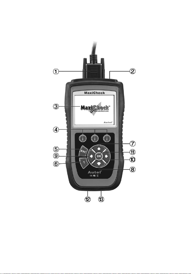
3.1 Tool Description
1) CONNECTOR -- Connects the scan tool to the vehicle‘s Data
Link Connector (DLC).
2) External DC Power Port – Connects the 12 volt power adapter
to power the tool when disconnected from the vehicle.
3) LCD DISPLAY -- Indicates test results. TFT color display (320
x 240 dpi).
Page 10

8
4) FUNCTION BUTTON – Corresponds with ―buttons‖ on
screen for executing commands.
5) ESC BUTTON -- Cancels a selection (or action) from a
menu or returns to the previous screen.
6) HELP BUTTON -- Provides help information and Code
Breaker function.
7) UP SCROLL BUTTON -- Moves up through menu and
submenu items in menu mode. When more than one screen of
data is retrieved, moves up through the current screen to the
previous screens for additional data. When looking up DTC, it is
used to change value of selected character.
8) DOWN SCROLL BUTTON -- Moves down through
menu and submenu items in menu mode. When more than one
screen of data is retrieved, moves down through the current
screen to next screens for additional data. When looking up DTC,
it is used to change value of selected character.
9) LEFT SCROLL BUTTON -- When look up DTC
definitions, moves to previous character and views additional
information on previous screens if DTC definition covers more
than one screen; views previous screen or previous frames of
recorded data. It is also used to view previous trouble code
when viewing DTCs.
10) RIGHT SCROLL BUTTON -- When look up DTC
definitions, moves to next character and view additional
information on next screens if DTC definition covers more than
one screen; views next screen or next frames of recorded data..
It is also used to view next trouble code when viewing DTCs.
11) OK BUTTON -- Confirms a selection (or action) from a
menu.
12) USB CONNECTOR -- Connects the scan tool to the PC for
printing and updating.
13) SD Card Slot – Holds the System SD card.
Page 11

9
3.2 Specifications
1) Display: TFT color display (320 x 240 dpi)
2) Operating Temperature: 0 to 60°C (32 to 140 F°)
3) Storage Temperature: -20 to 70°C (-4 to 158 F°)
4) External Power: 12.0 to 18.0 V power provided via vehicle
battery or adapter.
5) Dimensions:
Length Width Height
212 mm (8.35‖) 110.5 mm (4.35‖) 37.5 mm (1.48‖)
6) Weight: 0.28kg(without wire) 0.484kg(with wire)
3.3 Accessories Included
1) User‟s Manual -- Instructions on tool operations.
2) CD -- Includes user‘s manual, update software, and etc.
3) OBD2 cable -- Provides power to tool and communicates
between tool and vehicle.
4) USB cable -- Used to upgrade the scan tool, and to print
retrieved data.
5) SD card -- Contains the scan tool‘s operation software and
applications.
6) Carry case -- A nylon case to store the scan tool when not in use.
3.4 Keyboard
No solvents such as alcohol are allowed to clean the keypad or display.
Use a mild nonabrasive detergent and a soft cotton cloth. Do not soak
the keypad as the keypad is not waterproof.
3.5 Power
Before using the scan tool, you must provide power to the scan tool.
There are two methods for providing power to the scan tool.
DC external power adapter.
Cable connection to vehicle.
Page 12
10
During vehicle testing, power for the scan tool is usually provided
through the vehicle cable connection. When the scan tool is not
connected to a vehicle, the scan tool can be powered with an AC/DC
external power adapter.
While the scan tool is powered via the vehicle Data Link Connector
(DLC), just follow the steps below to turn on the scan tool:
1) Connect the Cable to scan tool.
2) Find DLC on vehicle.
A plastic DLC cover may be found for some vehicles and you
need to remove it before plugging the OBD2 cable.
3) Plug the cable to the vehicle‘s DLC.
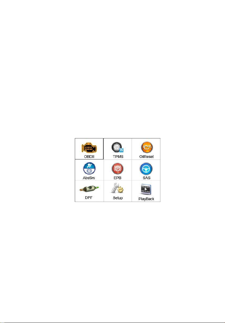
4) Power up the scan tool , and wait for the Main Screen to
appear.(figure 3.1)
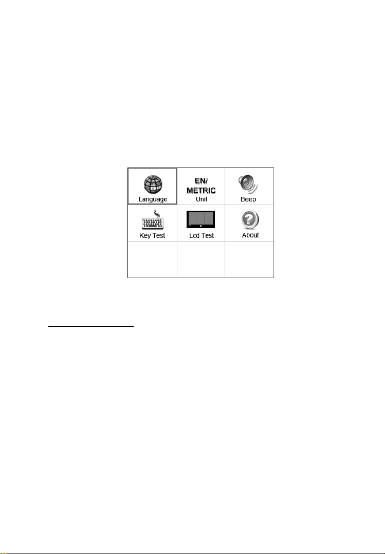
3.6 System Setup
The System Setup functions allow you to adjust default settings and
view information about the scan tool.
1) Language: Selects the desired language.
2) Unit of measure: Sets the unit of measure to English or Metric.
3) Beep Set: Turns on/off beep.
4) LCD Test: Checks if the LCD display is working properly.
5) Key Test: Checks if the keyboard is working properly.
Figure 3.1
Page 13
11
6) About: Provides information of the scan tool.
Settings of the unit will remain until change to the existing
settings is made.
To enter the Setup menu
From the Main Screen: Use LEFT/RIGHT scroll button to select
Setup, and press the OK button. Following the instructions to do
adjustments and settings could make your diagnosis more
conveniently and easily. (Figure 3.2)
Figure 3.2
Language Setup
English is the default language.
1) From System Setup screen, use the UP/DOWN scroll button
and LEFT/RIGHT scroll button to select Language, and press
the OK button.
2) Use the UP/DOWN scroll button to select the desired language
and press the OK button to save your selection and return to
previous screen. (Figure 3.3)
Page 14

12
Figure 3.3
Unit of Measure
Metric is the default measurement unit.
1) From System Setup screen, use the LEFT/RIGHT scroll button
to select EN/METRIC and press the OK button.
2) From Unit of Measure screen, use the LEFT/RIGHT scroll
button to select the desired unit of measurement. (Figure 3.4 )
Figure 3.4
3) Press the OK button to save your selection and return to previous
menu. Or, press the ESC button to exit without saving.
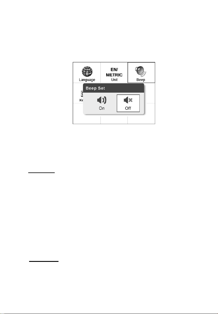
Beep Set
The default setting is Beep On.
Page 15
13
1) From System Setup screen, use the UP/DOWN scroll button
and LEFT/RIGHT scroll button to select Beep Set and press the
OK button.
2) From Beep Set menu, use the LEFT/RIGHT scroll button to
select ON or OFF to turn on/off the beep. (Figure 3.5)
Figure 3.5
3) Press the OK button to save your selection and return to
previous menu. Or, press the ESC button to exit without saving.
Key Test
The Key Test function checks if the keyboard is working properly.
1) From System Setup screen, use the UP/DOWN scroll button
and LEFT/RIGHT scroll button to select Key Test, and press
the OK button.
2) Press any key to start test. When you press a key, the edge around
corresponding key on the screen should turn to red. Otherwise,
the key is not functioning properly.
3) Double press ESC to return to previous menu.
LCD Test
The LCD Test function checks if the LCD display is working
normally.
Page 16
14
1) From System Setup screen, use the UP/DOWN scroll button
and LEFT/RIGHT scroll button to select LCD Test, and press
the OK button.
2) Look for missing spots in the red, green, blue, black and white
LCD display.
3) When completed, press the ESC button to exit.
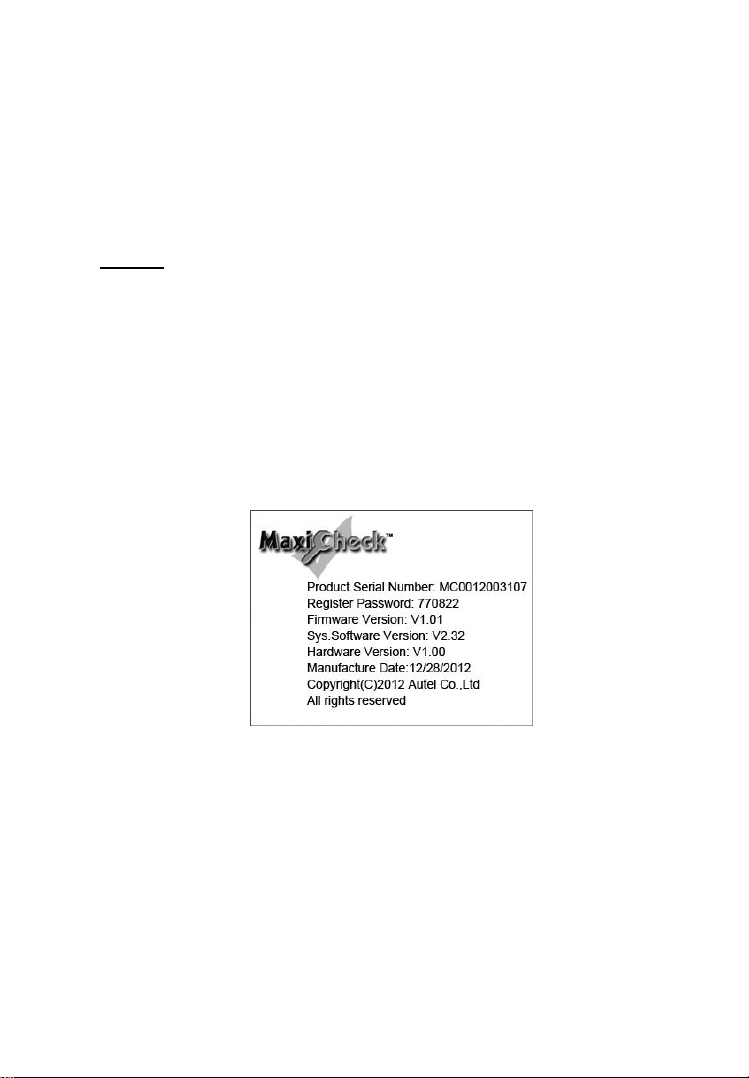
About
The About function allows viewing of some important information
such as serial number and software version number of the scanner.
1) From System Setup screen, use the UP/DOWN scroll button
and LEFT/RIGHT scroll button to select About and press the
OK button; wait for the About screen to appear.
2) View tool information on screen. (Figure 3.6) Press the ESC
button to exit without saving.
3.7 Vehicle Coverage
On the basis of all OBD II compliant vehicles, including those
equipped with universal protocol -- Control Area Network (CAN),
MaxiCHECK Series Scanner expands vehicle system coverage and
offers more diagnostic power to the vehicle technicians. Featuring
expanded global vehicle coverage, the scan tool offers technicians a
significant improvement on model years covered by supported
Figure 3.6
Page 17

15
manufactures. In addition to adding new vehicle coverage through
2011/2012, we‘ve also worked backwards to include non-OBDII
vehicles, which can be diagnosed by setting up with optional OBDI
adaptors.
For OBDII Diagnostics: 1996 and newer vehicles.
For Oil light / Service Reset : ACURA, HONDA, INFINITI,
ISUZU, LEXUS, NISSAN, SCION, TOYOTA, ABARTH, ALFA
ROMEO, AUDI, BENZ, BMW, CITROEN, FIAT, JAGUAR,
LANCIA, LAND ROVER, MINI, OPEL, PEUGEOT, SAAB,
SMART, SPRINTER, VW, VOLVO, CHRYSLER, FORD, GM,
JEEP, LINCOLN, MERCURY, OIDSMOBILE
For EPB Service: HONDA, TOYOTA, AUDI , BENZ , BMW ,
CITROEN , JAGUAR , LANDROVER , OPEL, PEUGEOT,
RENAULT, VW, VOLVO
For TPMS Service: ACURA, HONDA, HYUNDAI, INFINITI,
KIA, LEXUS, MAZDA, MITSUBISHI, NISSAN, SCION,
SUBARU, TOYOTA, BENZ, JAGUAR, LANDROVER, SAAB,
VOLVO, BUICK, CADILLAC, CHEVROLET, CHRYSLER,
DODGE, FORD, GM, HUMMER, JEEP, LINCOLN, MERCURY,
PONTIAC, SATURN.
For ABS/SRS : GM, CHRYSLER, FORD, AUDI, ABARTH,
ALFA, BENZ, BMW, BENTLEY, BUGATTI, CITROEN, DACIA,
EU FORD, FIAT, JAGUAR, LANDROVER, LANCIA, MINI,
MAYBACH, OPEL, PEUGEOT, PORSCHE, RENAULT, SAAB,
SMART, SEAT, SKODA, SPRINTER, VW, VAUXHALL, VOLVO,
AU FORD, HOLDEN, ACURA, DAEWOO, HONDA, HYUNDAI,
ISUZU, INFINITI, KIA, LEXUS, MAZDA, MITSUBISHI,
NISSAN, SCION, SUBARU, SUZUKI, TOYOTA.
For SAS: AU FORD, ACURA, HONDA, HYUNDAI, INFINITI,
KIA, LEXUS, NISSAN, SCION, SUBARU, SUZUKI, TOYOTA,
ABARTH, ALFA, BENZ, BMW, CITROEN, DACIA, EU FORD,
FIAT, JAGUAR, LANCIA, LAND ROVER, MINI, MAYBACH,
OPEL, PEUGEOT, RENAULT, VAUXHALL, FORD, CHRYSLER,
GM
Page 18

16
For DPF : CITROEN, PEUGEOT, BMW, RENAULT, ALFA,
BENZ, EU FORD, FIAT, JAGUAR, LANCIA, LAND ROVER,
MINI, OPEL, VAUXHALL, FORD, CHRYSLER, GM, AU FORD,
ACURA, HONDA, INFINITI, LEXUS, MAZDA, NISSAN, SCION,
TOYOTA.
3.8 Product Troubleshooting
Vehicle Linking Error
A communication error occurs if the scan tool fails to communicate
with the vehicle‘s ECU (Engine Control Unit). You need to do the
following to check up:
Verify that the ignition is ON.
Check if the scan tool‘s connector is securely
connected to the vehicle‘s DLC.
Turn the ignition off and wait for about 10 seconds. Turn the
ignition back to on and continue the testing.
Verify the control module is not defective.
Operating Error
If the scan tool freezes, then an exception occurs or the vehicle‘s
ECU (Engine Control Unit) is too slow to respond to requests. You
need to do the following to reset the tool:
Reset the scan tool.
Turn the ignition off and wait for about 10 seconds. Turn the
ignition back to on and continue the testing.
Scan tool doesn‟t power up
If the scan tool won‘t power up or operates incorrectly in any other
way, you need to do the following to check up:
Check if the scan tool‘s connector is securely connected to the
vehicle‘s DLC;
Check if the DLC pins are bent or broken. Clean the DLC pins if
necessary.
Check vehicle battery to make sure it is still good with at least 8.0
volts.
Page 19
17
4. Playback Data
The Playback Data function allows viewing data from last test
recorded by the scan tool.
NOTE: The amount of files that can be saved depends on the
space available in the SD card.
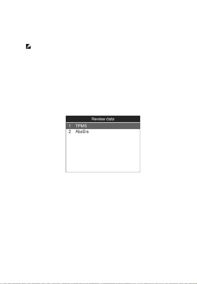
4.1 Reviewing Data
1) Use the LEFT/RIGHT scroll button to select Playback from
Main Screen (Figure 3.1), and press the OK button. Wait for
the Review data screen to appear. The recorded files are
identified by different diagnostic functions, such as OBDII
diagnostics, TPMS, OilReset, ABS/SRS, EPB, SAS and DPF
and will be saved in corresponding folders.
Figure 4.1
2) Select the desired item you want to review and press OK button
to continue. (Take TPMS as an example: To review data saved
in the TPMS function, select TPMS in the Review data menu.
Then press OK button to continue.)
If no data from previously tested vehicle is recorded, a message
―No data available!‖ shows on the screen.
Page 20
18
Figure 4.2
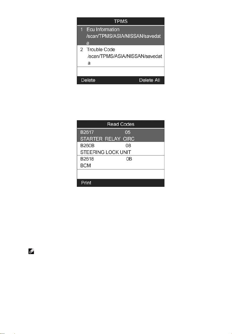
3) Use the UP/DOWN scroll button to select the desired item from
TPMS menu, and press the OK button.
Figure 4.3
4.2 Deleting Data
By selecting Delete on the screen, you are allowed to erase the
selected data on the scan tool. Review the recordings thoroughly
before erasing. You could also erase all recordings by select Delete
All.
NOTE: Don’t use Delete All unless you are definitely sure what
you are going to proceed.
4.3 Printing Data
Print option allows you to print the recorded files to your computer
and then to the printer.
For more details, please refer to chapter 12.1 Print Data.
Page 21

19
5. OBDII Diagnostics
The OBD II Diagnostics function is a fast-access option that allows
you to carry out a quick test on the engine system of OBD II
vehicles.
When more than one vehicle control module is detected by the
scan tool, you will be prompted to select the module where the
data may be retrieved. The most often to be selected are the
Power train Control Module [PCM] and Transmission Control
Module [TCM].
CAUTION: Don’t connect or disconnect any test equipment with
ignition on or engine running.
1) Turn the ignition off.
2) Locate the vehicle‘s 16-pin Data Link Connector (DLC).
3) Plug the scan tool cable connector into the vehicle‘s DLC.
4) Turn the ignition on. Engine can be off or running.
5) Turn on the scan tool. Select OBDII from the Main Screen.
(Figure 3.1)
6) Press the OK button to wait for the Menu to appear. A sequence
of messages displaying the OBDII protocols will be observed
on the display until the vehicle protocol is detected.
If the scan tool fails to communicate with the vehicle’s ECU
(Engine Control Unit) more than three times, a “LINKING
ERROR!” message shows up on the display.
Verify that the ignition is ON.
Check if the scan tool‘s OBD II connector is securely
connected to the vehicle‘s DLC.
Verify that the vehicle is OBD2 compliant.
Turn the ignition off and wait for about 10 seconds. Turn the
ignition back to on and repeat the procedure from step 5.
If the “LINKING ERROR” message does not go away, then
there might be problems for the scan tool to communicate
Page 22
20
with the vehicle. Contact your local distributor or the
manufacturer’s customer service department for assistance.
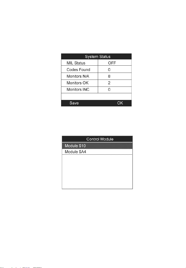
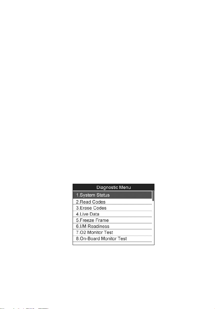
7) View a summary of system status (MIL status, DTC counts,
Monitor status) on screen. (Figure 5.1 ) Press ESC button for
Diagnostic Menu (Figure 5.3) to come up.
Figure 5.1
If more than one module is detected, you will be prompted to
select a module before testing. (Figure 5.2 )
Use the UP/DOWN scroll button to select a module and press
the OK button.
5.1. Read Codes
Reading Codes can be done with the key on engine off (KOEO)
or with the key on engine running (KOER).
Figure 5.2
Page 23
21
Stored Codes are also known as “hard codes”, which are fault
codes, or trouble codes that have been stored in the vehicle
computer memory because the faults have reoccurred for
more than a specified amount of key-cycles. These codes will
cause the control module to illuminate the malfunction
indicator light (MIL) when emission-related fault occurs.
Pending Codes are also referred to as “maturing codes” or
“continuous monitor codes”. They indicate problems that the
control module has detected during the current or last driving
cycle but are not considered serious yet. Pending Codes will
not turn on the malfunction indicator lamp (MIL). If the fault
does not occur within a certain number of warm-up cycles, the
code clears from memory.
Permanent Codes are DTCs that are "confirmed" and are
retained in the non-volatile memory of the computer until the
appropriate monitor for each DTC has determined that the
malfunction is no longer present and is not commanding the
MIL on. Permanent DTC shall be stored in non-volatile
memory and may not be erased by any diagnostic services or
by disconnecting power to ECU.
1) Use UP/DOWN scroll button to select Read Codes from
Diagnostic Menu and press OK button. (Figure 5.3 )
Figure 5.3
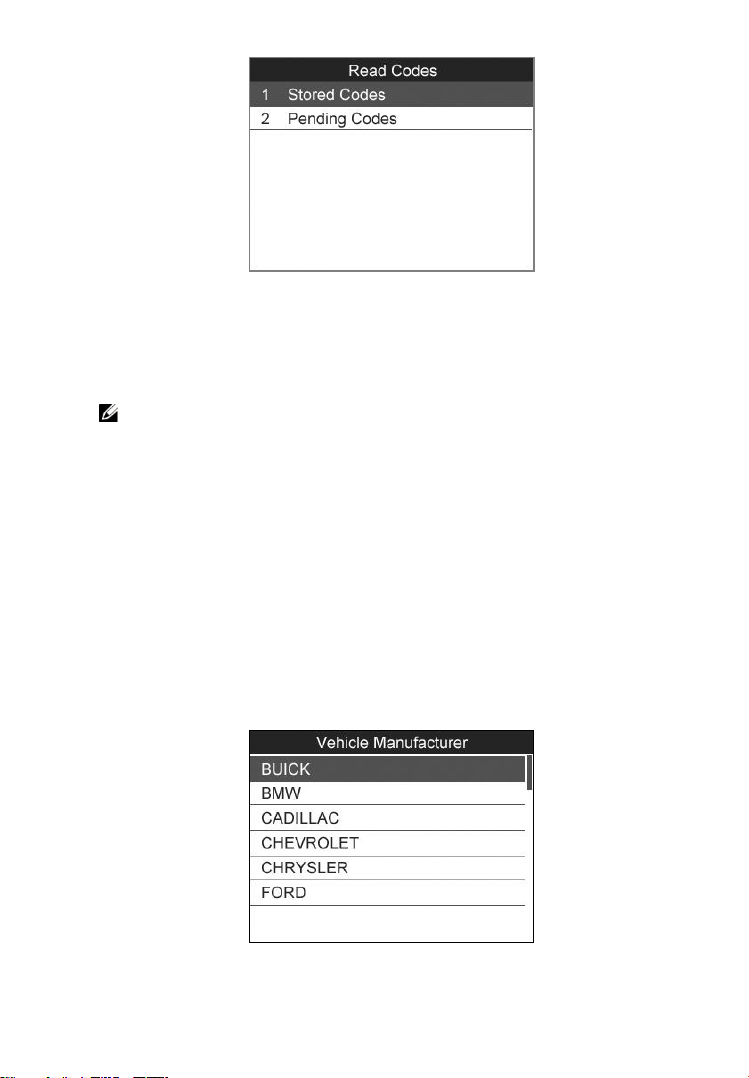
2) Use the UP/DOWN scroll button to select Stored Codes or
Pending Codes from the Read Codes menu and press the OK
button. (Figure 5.4 )
Page 24
22
Figure 5.4
If there is not any Diagnostic Trouble Code, the display indicates
―No (pending) codes are stored in the module!‖ Wait a few
seconds or press any key to return to previous screen.
NOTE: Permanent Codes function is available for merely
vehicles supporting the CAN protocols.
3) View DTCs and their definitions on screen.
4) If more than one DTC is found, use the UP/DOWN scroll button
to check all the codes.
If retrieved DTCs contain any manufacturer specific or enhanced
codes, a ―Manufacturer specific codes are found! Press any key
to select vehicle make!‖ message comes up prompting you to
select vehicle manufacturer to view DTC definitions. Use
UP/DOWN scroll button to select manufacturer and then press
OK button to confirm.
Figure 5.5
Page 25
23
If the manufacturer of your vehicle is not listed, use the
UP/DOWN scroll button to select Other and press the OK
button.
5.2. Erasing Codes
CAUTION: Erasing the Diagnostic Trouble Codes may allow the
scan tool to delete not only the codes from the vehicle’s on-board
computer, but also “Freeze Frame” data and manufacturer specific
enhanced data. Further, the I/M Readiness Monitor Status for all
vehicle monitors is reset to Not Ready or Not Complete status. Do
not erase the codes before the system has been checked completely
by a technician.
NOTE: Erasing codes does not mean that trouble codes in
ECU have been eliminated completely. As long as there is
fault with the vehicle, the trouble codes keeps on presenting.
This function is performed with key on engine off (KOEO). Do
not start the engine.
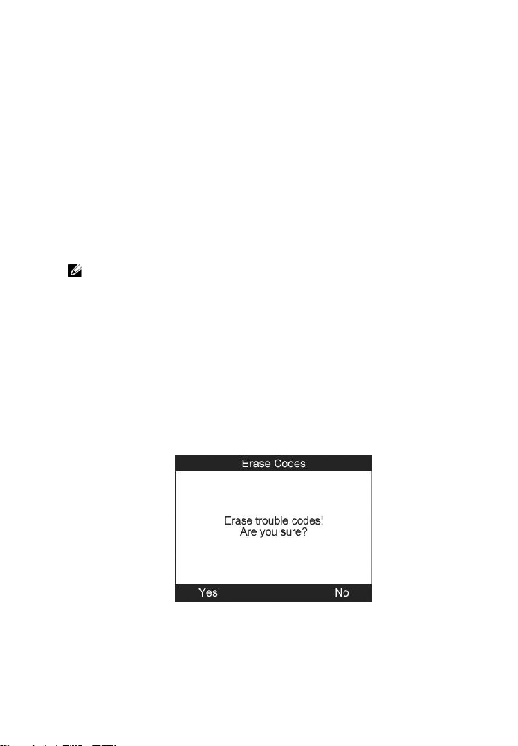
1) Use the UP/DOWN scroll buttons to select Erase Codes from
Diagnostics Menu and press the OK button. (Figure 5.3)
2) A warning message comes up asking for your confirmation.
(Figure 5.6)
Figure 5.6
If you do not want to proceed with erasing codes, press ESC
button or select NO to exit and return to previous screen.
Page 26
24
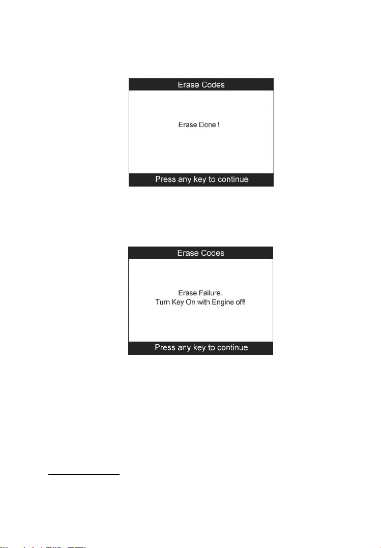
3) Press the OK button to confirm.
If the codes are cleared successfully, an ―Erase Done!‖
confirmation message shows on the display.( Figure 5.7)
Figure 5.7
If the codes are not cleared, then an ―Erase Failure. Turn Key
on with Engine off!‖ message appears. (Figure 5.8)
4) Press any button to return to Diagnostic Menu.
5.3. Live Data
In this function, you can not only read the live data but also record
data for later review.
Viewing Data
Figure 5.8
Page 27
25
The View Data function allows viewing of live or real time PID
data of vehicle‟s computer module(s).
1) To view live data, use the UP/DOWN scroll button to select Live
Data from Diagnostic Menu and press the OK button. (Figure
5.3)
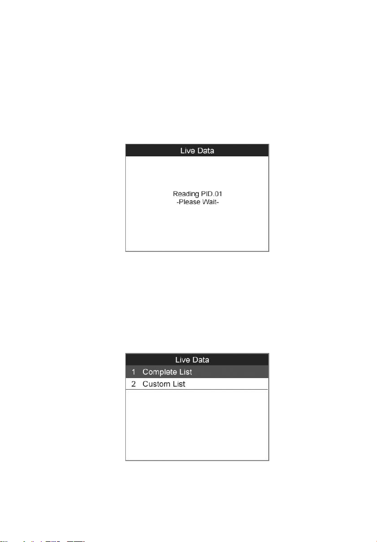
2) Wait a few seconds while the scan tool validates the PID MAP.
(Figure 5.9)
Figure 5.9
A. Viewing Complete List
1) To view complete set of data, use UP/DOWN scroll button to
select Complete List from Live Data menu and press the OK
button. (Figure 5.10)
Figure 5.10
Page 28
26
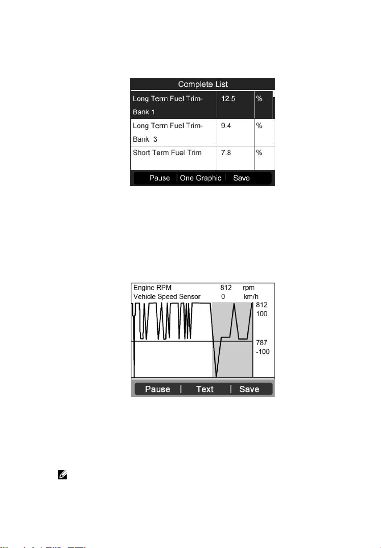
2) View live PIDs on the screen. Use the UP/DOWN scroll button
for more PIDs if additional information is available on more than
one page.( Figure 5.11)
Figure 5.11
If the ―Graphics‖ on the bottom appears when a PID is
highlighted, graphic information is available. Select
Graphics to view graph. (Figure 5.12). PID name, current
value, maximum and minimum values are displayed on the
screen.
Figure 5.12
If the ―Merge Graph‖ on the bottom appears when a PID is
selected to view, merged graph information is available.
(Figure 5.13)
NOTE: Merge Graph can be used to compare two related
parameters in graphic mode, which is especially convenient in
Page 29
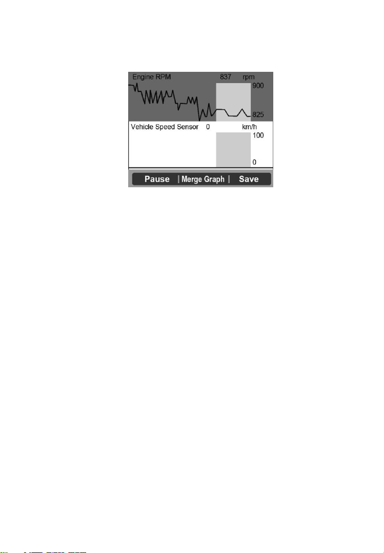
27
the Custom List option where you could select two interacted
parameter to merge and see their relationship.
Figure 5.13
Select Text to return to text viewing of PID data.
Select Save to record retrieved live data and PID graphs.
Select Pause to suspend viewing. You could resume the
viewing process again by selecting Start.
3) Press the ESC button to return to previous menu.
B. Viewing Custom List
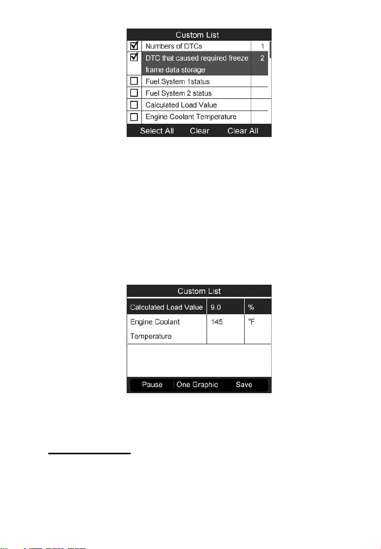
1) To view customized PID data, use the UP/DOWN scroll button to
select Custom List from Live Data menu and press the OK
button.( Figure 5.10)
2) Use the UP/DOWN scroll button to move up and down to the
desired items and click Select button to confirm. The selected
parameters are marked with solid squares.( Figure 5.14 )
Page 30
28
Figure 5.14
The number to the right of selected item indicates sequence
of this item.
If you want to deselect the item, press Clear button.
To select all the items on the screen, press Select All button.
To clear all the selected items on the screen, press Clear All
button.
3) Press the OK button to view selected PIDs on screen.
Figure 5.15
4) Use the ESC button to return to previous menu.
Recording Data
The Record Data function allows recording vehicle modules‟
Parameter Identification (PID) data to help diagnose
intermittent vehicle problems. You could save data files to the
Page 31

29
SD card and then use the Playback function to view the saved
files.
NOTE: The length of time for each frame varies per vehicle.
Generally, one frame of data is about 1/4 second, or 4 frames per
second.
1) To record live data, with the live data screen displaying, select
Save on the bottom. The scan tool will start timing to record
retrieved live data and PID graphs.
If you record live data under text mode, following screen
shows:
Figure 5.16
If you record live data under graph mode, following screen
shows:
Figure 5.17
Page 32

30
NOTE: The scan tool can only playback text data even
though the data is saved in graphic mode.
2) When there is not enough memory space, a warning message
prompting to delete previously recorded data.
Figure 5.18
If you wish to delete the data, select Yes and save currently
retrieved data in the SD card.
If you do not wish to delete the data, select No to return to
previous screen.
3) Select Pause to suspend recording. You could resume the
recording process again by selecting Start.
4) You may review the saved data in Playback function.
5) Press ESC button to exit.
5.4. Freeze Frame
Freeze Frame Data allows the technician to view the vehicle‘s
operating parameters at the moment a DTC (Diagnostic Trouble
Code) is detected. For example, the parameters may include engine
speed (RPM), engine coolant temperature (ECT), or vehicle speed
sensor (VSS) etc. This information will aid the technician by
allowing the parameters to be duplicated for diagnostic and repair
purposes.
1) To view freeze frame data, use the UP/DOWN scroll button to
select Freeze Frame from Diagnostic Menu and press the OK
button. (Figure 5.3 )
Page 33

31
2) Wait a few seconds while the scan tool validates the PID MAP.
3) If retrieved information covers more than one screen, use the
DOWN scroll button, as necessary, until all the data have been
shown up. (Figure 5.19)
Figure 5.19
If there is no available freeze frame data, an advisory message
―No freeze frame data stored!‖ shows on the display.
4) Select Save to record freeze frame. A confirming message ―Save
success!‖ shows on the display and scan tool return to previous
menu.
5) If you don‘t want to save the freeze frame data, press ESC
button to return to previous screen.
5.5. Retrieving I/M Readiness Status
I/M Readiness function is used to check the operations of the
Emission System on OBD2 compliant vehicles. It is an excellent
function to use prior to having a vehicle inspected for
compliance to a state emissions program.
CAUTION - By clearing trouble codes you also clear the readiness
status for the individual emission system readiness tests. In order
to reset these monitors, the vehicle must be driven through a
complete drive cycle with no trouble codes in memory. Times for
reset vary depending on vehicle.
Page 34

32
Some latest vehicle models may support two types of I/M
Readiness tests:
A. Since DTCs Cleared - indicates status of the monitors since the
DTCs are erased.
B. This Drive Cycle - indicates status of monitors since the
beginning of the current drive cycle.
An I/M Readiness Status result of “NO” does not necessarily
indicate that the vehicle being tested will fail the state I/M
inspection. For some states, one or more such monitors may be
allowed to be “Not Ready” to pass the emissions inspection.
“OK” -- Indicates that a particular monitor being checked has
completed its diagnostic testing.
“INC” -- Indicates that a particular monitor being checked has
not completed its diagnostic testing.
“N/A” -- The monitor is not supported on that vehicle.
1) Use the UP/DOWN scroll button to select I/M Readiness from
Diagnostic Menu and press OK button. (Figure 5.3)
2) Wait a few seconds while the scan tool validates the PID MAP.
3) If the vehicle supports both types of tests, then both types will be
shown on the screen for selection. (Figure 5.20)
Figure 5.20
Page 35

33
4) Use the UP/DOWN scroll button, as necessary, to view the status
of the MIL light (“ON” or “OFF) and the following monitors:
For spark ignition engines:
MIS -- Misfire Monitor
FUEL -- Fuel System Monitor
CCM -- Comprehensive Component Monitor
EGR – EGR System Monitor
O2S -- O2 Sensors Monitor
CAT -- Catalyst Monitor
EVAP -- Evaporative System Monitor
HTR -- O2 Sensor Heater Monitor
AIR -- Secondary Air Monitor
HCAT -- Heated Catalyst Monitor
For compression ignition engines:
MIS -- Misfire Monitor
FUEL -- Fuel System Monitor
CCM -- Comprehensive Component Monitor
EGR – EGR System Monitor
HCCAT -- NMHC Catalyst Monitor
NCAT -- NOx Aftertreatment Monitor
BP -- Boost Pressure System Monitor
EGS -- Exhaust Gas Sensor Monitor
PM -- PM Filter Monitor
Page 36

34
Figure 5.21
5) If the vehicle supports readiness test of ―This Drive Cycle‖, a
screen of the following displays: (Figure 5.22)
Figure 5.22
6) Use the UP/DOWN scroll button for more PIDs if additional
information is available on more than one page. Or use the
LEFT/RIGHT scroll button to view PIDs in the previous/next
page.
7) Press the ESC button to return to Diagnostic Menu.
5.6. O2 Monitor Test
OBD2 regulations set by SAE require that relevant vehicles
monitor and tests on the oxygen (O2) sensors to identify problems
related to fuel efficiency and vehicle emissions. These tests are not
on-demand tests and they are done automatically when engine
operating conditions are within specified limits. These test results
Page 37

35
are saved in the on-board computer's memory.
The O2 Monitor Test function allows retrieval and viewing of O2
sensor monitor test results for the most recently performed tests
from the vehicle's on-board computer.
The O2 Monitor Test function is not supported by vehicles which
communicate using a controller area network (CAN). For O2
Monitor Test results of CAN-equipped vehicles, see chapter
“On-Board Mon. Test”.
1) Use the UP/DOWN scroll button to select O2 Monitor Test
from Diagnostic Menu and press OK button. (Figure 5.3)
2) Wait a few seconds while the scan tool validates the PID MAP.
3) Use the UP/DOWN scroll button to select O2 sensor from O2
Monitor Test menu and press OK button. (Figure 5.23)
Figure 5.23
If the vehicle does not support the mode, an advisory message
will be displayed on the screen. (Figure 5.24)
Page 38

36
Figure 5.24
4) View test results of selected O2 sensor. (Figure 5.25)
Figure 5.25
5) Use the UP/DOWN scroll button to view more screens of data if
additional information is available in more than one page.
6) Press the ESC button to return to the previous menu.
5.7. On-Board Monitor Test
The On-Board Monitor Test is useful after servicing or after
erasing a vehicle‟s control module memory. The On-Board
Monitor Test for non-CAN-equipped vehicles retrieves and
displays test results for emission-related power train components
and systems that are not continuously monitored. The On-Board
Monitor Test for CAN-equipped vehicles retrieves and displays
test results for emission-related power train components and
systems that are and are not continuously monitored. Test and
components IDs are determined by the vehicle manufacturer.
Page 39

37
In this test, there are typically a minimum value, a maximum value,
and a current value for each monitor. By comparing the current value
with the minimum and maximum value, the scan tool will determine
if it is OK.
1) Use the UP/DOWN scroll button to select On-Board Monitor
Test from Diagnostic Menu and press the OK button. (Figure
5.3)
2) Wait a few seconds while the scan tool validates the PID MAP.
3) The scan tool will prompt you to select the vehicle make.
Figure 5.26
4) After you select the vehicle manufacturer, the scan tool shows
the On-Board Monitors tests for specific monitoring systems.
5) From On-Board Monitor Test menu, use the UP/DOWN scroll
button to select a test to view and press the OK button.
Figure 5.27
Page 40

38
If the vehicle under test does not support the mode, an
advisory message will be displayed on the screen.
Figure 5.28
For CAN-equipped vehicles, test selections can be as below:
Figure 5.29
6) Use the UP/DOWN scroll button to select the desired monitor
from On-Board Monitor Test menu and press the OK button.
7) View test data on screen.
Page 41

39
Figure 5.30
For CAN-equipped vehicles, test results displayed can be as
below:
Figure 5.31
8) Press ESC button to return to the previous menus.
5.8. Component Test
The Component Test function allows initiating a leak test for the
vehicle's EVAP system. The scan tool itself does not perform the
leak test, but commands the vehicle's on-board computer to start
the test. Different vehicle manufacturers might have different
criteria and methods for stopping the test once it has been started.
Before starting the Component Test, refer to the vehicle service
manual for instructions to stop the test.
1) Use the UP/DOWN scroll button to select Component Test from
Diagnostic Menu and press the OK button. (Figure 5.3)
2) Wait for the scan tool to display the Component Test menu.
Page 42

40
Figure 5.32
3) If the test has been initiated by the vehicle, a confirmation
message will be displayed on the screen.
Figure 5.33
Some vehicles do not allow scan tools to control vehicle
systems or components. If the vehicle under test does not
support the EVAP Leak Test, an advisory message is
displayed on the screen.
Figure 5.34
Page 43

41
4) Wait a few seconds or press any key to return to previous screen.
5.9. Viewing Vehicle Information
The Vehicle Info. function enables retrieval of Vehicle
Identification No. (VIN), Calibration ID Nos. (CINs),
Calibration Verification Nos. (CVNs) and In-use Performance
Tracking on 2000 and newer vehicles that support Mode 9.
1) Use UP/DOWN scroll button to select Vehicle Info. from the
Diagnostic Menu and press OK button. (Figure 5.3)
2) An advisory message comes up to remind you. Wait a few
seconds or press any key to continue.
Figure 5.35
3) Wait for the scan tool to display the Vehicle Info. menu.
Figure 5.36
Page 44

42
If the vehicle does not support this mode, a message shows on
the display warning that the mode is not supported.
4) From Vehicle Info. Menu, use the UP/DOWN scroll button to
select an available item to view and press the OK button.
5) View retrieved vehicle information on screen.
Figure 5.37
6) Press the ESC button to return previous menu
5.10. Modules Present
The Modules Present function allows viewing of the module IDs
and communication protocols for OBD2 modules in the vehicle.
1) Use the UP/DOWN scroll button to select Modules Present
from Diagnostic Menu and press OK button. (Figure 5.3)
2) View modules present with their IDs and communication
protocols.
Figure 5.38
Page 45

43
3) Select Save to save the modules data and return to previous
menu. Or press ESC button to exit.
5.11. DTC Lookup
The DTC Lookup function allows user to search definitions of
DTC stored in built-in DTC library.
1) Use the UP/DOWN scroll button to select DTC Lookup from
Diagnostic Menu and press OK button. (Figure 5.3)
2) Wait for the scan tool to display the DTC Lookup screen.
Figure 5.39
3) Select Show and a soft keyboard will pop up. Use
LEFT/RIGHT button and UP/DOWN button to move to the
desired character, then press OK button to confirm.
Figure 5.40
4) After you input the DTC code, select Finish and the scan tool
will display this code‘s definition on screen.
Page 46

44
5) Press Yes or OK button to proceed. The scan tool will display
DTC definition as below.
Figure 5.41
Figure 5.42
Use the LEFT/RIGHT scroll button to view the previous /
next DTC.
Select Save to record code definition.
For manufacturer specific codes, you need to select a vehicle
make on an additional screen to look for DTC definitions.
If definition could not be found (SAE or Manufacturer
Specific), the scan tool displays ―Please refer to vehicle
service manual!‖
6) Press No or ESC button to return to previous menu.
Page 47

45
6. TPMS (Tire Pressure Monitor System)
This function allows user quickly look up vehicle TPMS information
and reset procedures and perform Tire Pressure Monitor System
diagnostics.
With the tool properly connected to a vehicle's data link connector
(DLC), you can use the tool to read TPMS diagnostic trouble codes
(DTCs) and view live data streams from the vehicle's TPMS-related
ECUs. You can also save "recordings" of data readings and perform
special TPMS programming and reset procedures.
NOTE: All software screens shown in this manual are
examples, actual test screens may vary for each vehicle being
tested. Observe the menu titles and onscreen instructions to
make correct option selections.
NOTE: For some operations, you may need to activate the
TPMS sensors on the wheel. We offer a TPMS series of
products. For more information, please visit our website:
www.auteltech.com.
6.1. Enter the vehicle information
1) Turn the ignition off.
2) Make sure the car is properly blocked.
3) Connect the tool to vehicle and power on.
4) Turn the ignition on.
5) Select TPMS icon in the Main Screen (Figure 3.1) and press
OK button. A series of vehicle identification screens appears
for you to identify the vehicle. (Take Nissan as an example)
6) Select Nissan on the screen. This initiates communication with
the vehicle's computer and displays the next screen—TPMS
diagnostic function menu (Figure 6.1).
NOTE: If there is a linking error, a notice screen will show up.
Please refer to 3.8 Product Troubleshooting for more details.
Page 48

46
Figure 6.1
6.2. TPMS diagnostics
A. Read Codes
This function enables you to read TPMS-related diagnostic trouble
codes (DTCs) from a selected ECU.
1) From the TPMS diagnostic function menu (Figure 6.1), use the
UP/DOWN scroll button to select the Read Codes, and press
OK button.
2) The tool will display TPMS DTCs retrieved from the vehicle‘s
ECU for your viewing. Select ―Save‖ to store data for future
review, or press Esc button to exit without saving. (Figure 6.2).
Figure 6.2
B. Erase Codes
This function enables you to erase TPMS-related diagnostic trouble
codes (DTCs) in a selected ECU.
Page 49

47
1) From the TPMS diagnostic function menu (Figure 6.1), use the
UP/DOWN scroll button to select the Erase Codes, and press
OK button.
2) The tool will display a warning message for your confirmation.
Select ―Yes‖ to continue, ―No‖ to exit.
Figure 6.3
3) If the erase command is sent successfully, the screen will show
as below (Figure 6.4). Press any button to continue. To make
sure codes are erased clearly, run Read Codes again.
Figure 6.4
C. Live Data
This function enables you view TPMS-related data readings from a
selected ECU. With the live data screen displayed, you can view the
data in Text or graphical format, record and save files for later
viewing, sort the data, pause the readings and view past data, and
more.
Page 50

48
From the TPMS diagnostic function menu (Figure 6.1), use the
UP/DOWN scroll button to select the Live Data, and press OK
button.
Figure 6.5
All Data
1) From the Live Data menu (Figure 6.5), use the UP/DOWN
scroll button to select All Data and press the OK button.
2) The tool will display a list of all live sensor data. (Figure 6.6)
Figure 6.6
Press the corresponding FUNCTION BUTTON ‗Save‟ to store
the retrieved live data for later playback or printing.
Press the corresponding FUNCTION BUTTON ‗Stop Save‟ to
stop saving data and resume live sensor data retrieving.
Press the corresponding FUNCTION BUTTON ‗Pause‘ to
suspend live sensor data retrieving.
Page 51

49
Press the corresponding FUNCTION BUTTON ‗Continue‘ to
resume live sensor data retrieving.
If the ‗One Graphic‘ option is highlighted when a specific item
is selected, the graphic information is available.
When the sensor data is shown in graph, the tool offers two
more options: Two Graphic and Merge Graphic. The first
option can display two graphs on the same screen (Figure 6.7),
and the last option can merge the two graphs into one. (Figure.
6.8)
Figure 6.7
Figure 6.8
Press the corresponding FUNCTION BUTTON „Text‟ or the
ESC button to return to previous screen.
Custom List
Page 52

50
This option lets you select and view TPMS-related data readings for
specific components (sensors, switches, etc.) controlled by a specific
ECU.
1) To retrieve customized live sensor data, use the UP/DOWN
scroll button to select Custom List from Live Data and press
the OK button. (Figure 6.5)
2) Use the UP/DOWN scroll button to move to the desired item
and press the corresponding FUNCTION BUTTON ‗Select‘ to
choose.
Figure 6.9
The Selected items are marked with ticks on the left.
The number on the right indicates sequence of the selected
item.
Press the corresponding FUNCTION BUTTON ‗Clear‘ to
unselect items, or press the corresponding FUNCTION
BUTTON ‗Select All‘/‗Clear All‘ to select or unselect all
items.
3) Press the OK button to confirm your selection and retrieve the
selected live sensor data.
4) Press the ESC button to return to the previous menu.
D. Active Test
This function enables you to perform actuator test for a specific
component.
1) From the TPMS diagnostic function menu (Figure 6.1), use the
UP/DOWN scroll button to select the Active Test, and press
OK button.
Page 53

51
2) The tool will display a list of available active tests for the
vehicle being tested.
Figure 6.10
Taking Warning Lamp for example:
1) From Active Test Menu, use the UP/DOWN scroll button to
select Warning Lamp function. (Figure 6.10)
2) Press the corresponding FUNCTION BUTTON ‗ON‘or ―OFF‖
to check whether the warning lamp on the vehicle is turning on
or off. (Figure 6.11)
Figure 6.11
3) Press the ESC button to return to the previous menu.
E. Special Function
This function enables you to program and reset TPMS-related
components or write TPMS sensor IDs to the ECU.
Page 54

52
1) From the TPMS diagnostic function menu (Figure 6.1), use the
UP/DOWN scroll button to select the Special Function, and
press OK button.
2) The tool will display a list of available special functions for the
vehicle being tested.
Figure 6.12
Taking ID Regist for example:
1) From Special Function Menu, use the UP/DOWN scroll button
to select ID Regist function. (Figure 6.12)
2) The tool will communicate with vehicle computer and register
the TPMS sensor IDs to the ECU. When the registration is
completed, the screen displays as below.
Figure 6.13
F. Ecu Information
This function enables you to retrieve the ECU information.
Page 55

53
1) From the TPMS diagnostic function menu (Figure 6.1), use the
UP/DOWN scroll button to select the Ecu Information, and
press OK button.
2) The tool will display the Ecu information for your viewing and
saving.
Figure 6.14
3) Select Save option to save the information for later review or
press the ESC button to return to the previous menu.
Page 56

54
7. Oil Reset
7.1 General Information
The Engine Oil Life System calculates when to change the engine
oil and filter based on vehicle use. An oil change is required
whenever indicated by the display and according to the
recommended maintenance schedule. Whenever the oil is
changed, reset the system so it can calculate when the next oil
change is required. If a situation occurs where the oil is changed
prior to a service indicator being turned on, also reset the
system.
IMPORTANT: Always reset the engine oil life to 100% after
every oil change.
NOTE: All required work must be carried out before the
service indicators are reset. Failure to do so may result in
incorrect service values and cause DTCs to be stored by the
relevant control module.
NOTE: For some vehicles, the scan tool can perform added
functionality to reset additional service lights (maintenance
cycle, service interval). Taking BMW as an example, its
service reset function includes engine oil, spark plugs,
front/rear brakes, coolant, particle filter, brake fluid,
microfilter, vehicle inspection, exhaust emission inspection
and vehicle check.
All software screens shown in this manual are examples, actual test
screens may vary for each vehicle being tested. Observe the menu
titles and onscreen instructions to make correct option selections.
7.2 Reset Operation
1. Turn the ignition on but do not start the engine.
2. Turn on the scan tool and wait for the Main Screen to appear.
3. Select Oil Reset icon in the Main Screen (Figure 3.1) and wait
for the vehicle manufacturer screen. Choose the correct vehicle
make.
Page 57

55
There are two ways to perform the reset service.
Model
1.Explorer
2.Freestyle
3.Windstar
A. Manual Reset
Almost all Asian vehicles and most American and European
vehicles can be reset manually by technicians.
NOTE: In this manner, the scan tool will not communicate
with the vehicle being tested.
To finish this procedure, please follow these steps (Taking Ford as
an example):
1) From the vehicle make screen, select Ford and press OK
button.
Figure 7.1
2) Step by step, select the right options for your vehicle according
to each screen that appears.
Figure 7.2
Page 58

56
Year
1.2005
2.2003-2004
3.1998-2002
Manual Reset
1.Select Press Reset At Oil Change
from the setup control for the
current display mode.
2.Press Reset Control to reset
Oil change.
OK
Figure 7.3
3) After entering the vehicle information, the scan tool displays
manual reset message as below.
Figure 7.4
4) Follow the instructions to reset the service manually.
5) Press ESC button to exit.
B. Auto Reset
Most American and European vehicles can be reset automatically by
the scan tool.
NOTE: In this manner, the scan tool will communicate with
the vehicle being tested. If there is a linking error, please
refer to 3.8 product troubleshooting.
To finish this procedure, please follow these steps (Taking
PEUGEOT as an example):
1) From the vehicle make screen, select PEUGEOT and press OK
button.
Page 59

57
System
1.Instrument panel
2.BSI
PEUGEOT
1.206/206MUX
2.206+
3.207
4.307
5.308
6.406
Figure 7.5
2) Step by step, select the right options for your vehicle according
to each screen that appears.
Figure 7.6
3) After you have entered the vehicle information, the oil reset
screen will display as below.
Figure 7.7
Page 60

58
4) The Instrument Panel option enables you to finish oil reset
Oil Reset
1.Service Zero Reset
Service Zero Reset
Check the resetting of
the maintenance to zero.
Cancel
Service Zero Reset
Operation Completed.
Press any key to continue
service in one step by resetting the ECU to default values
automatically. The procedures work as below.
In the Oil Reset menu, select Service Zero Reset function
and press OK button.
Figure 7.8
The tool will automatically begin resetting the vehicle ECU
to default values.
When the resetting is finished, the tool will display a
confirmation message.
Figure 7.9
Figure 7.10
Page 61

59
5) The BSI option enables you to finish oil reset service
Oil Reset
1.Resetting to zero of the service
mileage
2.Maintenance
Resetting to zero
Maintenance mileage zero
reset carried out.
Press any key to continue
Maintenance
Period before service
(months)
6
First maintenance
threshold
china
Maintenance
limit(km)
7400
Finish Edit ESC
automatically and manually. The procedures work as below.
In the Oil Reset menu, select Resetting to zero of the
service mileage function and press OK button.
Figure 7.11
The tool will reset the oil service to zero automatically.
Figure 7.12
In the Oil Reset menu (Figure 7.11), select Maintenance
function and press OK button. The screen will display the
preset maintenance information of the vehicle. The
information items vary with different vehicles.
Figure 7.13
Page 62

60
For the First maintenance threshold, you have two choices.
1.China
2.Another country
Select the correct option and press OK button to save the
change.
Figure 7.14
For the Period before service or Maintenance limit, press
Edit key on the bottom to pop up a soft keyboard to
facilitate your input.
The three keyboard function keys work as below.
Finish --- When you finished the input, select this key to
confirm your input and exit.
Pre. --- Moves a space to the left.
Backspace --- Uses this key to erase the previous digit or
character when typing.
Figure 7.15
Page 63

61
NOTE: The data you input must be in the reasonable range,
Maintenance
Configuration carried out.
Press any key to continue
which is defined by the preset values in ECU. If you enter a data
out of range, the tool will display a warning message.
Figure 7.16
When you have finished your configuration, select Finish
key on the bottom of the screen, then the tool will begin the
oil reset service.
Figure 7.17
Page 64

62
8. EPB
This electric parking brake (EPB) function has a multitude of
uses to maintain the electronic braking systems safely and
effectively. The applications include deactivating/activating the
brake control system, assisting with brake fluid control, brake
diagnostics, opening and closing brake pads, setting brakes after
disc or pad replacement and also reading and clearing EPB/SBC
trouble codes. It is also capable of retrieving Fault Codes
information from the ECU.
8.1. EPB Safety
It may be dangerous to perform electric parking brake (EPB) system
maintenance, so before you begin the service work, please keep these
rules in mind.
Ensure that you are fully familiar with the braking system and
its operation before commencing any work.
The EPB control system may be required to be deactivated
before carrying out any maintenance/diagnostic work on the
brake system. This can be done from the tool menu.
Only carry out maintenance work when the vehicle is stationary
and on level ground.
Ensure that the EPB control system is reactivated after the
maintenance work has been completed.
NOTE: Autel accepts no responsibility for any accident or
injury arising from the maintenance of the Electric Parking
Brake system.
8.2. EPB Maintenance
1) Turn the ignition off.
2) Release the park brake and make sure the car is properly
blocked.
3) Connect the tool to vehicle and power on.
Page 65

63
4) Turn the ignition on.
System
1.EPB
2.ABS
5) Select EPB icon in the Main Screen (Figure 3.1) and wait for
the vehicle manufacturer screen. Choose the correct vehicle
make. (Take PEUGEOT as an example)
Figure 8.1
6) After you have selected the vehicle make, the electric parking
brake system screen will display as below.
7) In the electric parking brake system screen, use the UP/DOWN
button to select EPB to enter EPB system. In the EPB
diagnostic function, the tool can read codes, erase codes, record
live data, read ECU information, perform active test, and
perform special function. For the functions already being
described before, please refer to chapter 5. OBDII Diagnostics
for details.
Figure 8.2
Page 66

64
Diag. Menu
1. Read Codes
2. Erase Codes
3. Live Data
4. Active Test
5. ECU Information
6. Special Function
EPB
1.Brake cable replacement
2.Electric parking brake
replacement.
Brake cable replacement
1.Put in fitting/removal position
2.Cable tensioning
3.Electric parking brake
calibration.
Figure 8.3
Special Function
1) In the Diagnostic Menu (Figure 8.3), use the UP/DOWN
button to select Special Function to do the EPB test, which
includes Brake cable replacement and Electric parking
brake replacement.
Figure 8.4
2) In the EPB screen, use the UP/DOWN button to select Brake
cable replacement. The screen shows as below.
Figure 8.5
Page 67

65
In the Brake cable replacement screen, the tool can perform
Put in fitting/removal position
Activation in progress!
OK
Put in fitting/removal position
Positioning done.
To replace or remove the brake
cables, refer to the mechanical
schedule "Removal-replacement:
electric parking brake primary and
secondary cables"
Press any key to continue
three functions.
A. Put in fitting or removal position
This function enables you to fit in or remove the brake cable
safely and easily. It will take a few seconds to execute this
command.
Figure 8.6
When the job is done successfully, the tool will display a
message to confirm.
If the job fails to finish, the tool will display a message to remind
user of a problem. After you exit the diagnosis program, please
repair the problem immediately.
Figure 8.7
Page 68

66
Put in fitting/removal position
Activation done, a problem
occurred during the operation.
Press any key to continue
Cable tensioning
Cable tensioning done.
Now calibrate the Electric parking
brake (see “Electric parking
brake replacement” menu)
Press any key to continue
Cable tensioning
Activation in progress!
OK
Figure 8.8
B. Cable tensioning
Once the brake cable is fit in, you would use this function to
adjust its tension. It will take a few seconds to execute this
command.
Figure 8.9
When the job is done successfully, the tool will display a
message to confirm.
Figure 8.10
Page 69

67
If the job fails to finish, the tool will display a message to remind
Electric parking brake calibration
Activation in progress!
OK
Cable tensioning
Activation done, a problem
occurred during the operation.
Press any key to continue
user of a problem. After you exit the diagnosis program, please
repair the problem immediately.
Figure 8.11
C. Electric parking brake calibration
When both functions above have completed successfully, you
still need to calibrate the electric parking brake system.
This function is to check if the EPB is working correctly, which
should be performed after work has been completed on the EPB
or vehicle braking system. It will remove any air gap from the
brake pads and check the EPB pressure.
After you select this function, the tool will automatically work in
the following procedure.
Figure 8.12
Page 70

68
Electric parking brake calibration
Please wait! The tool should stop
and restart the communication
with the Electric parking brake
ECU.
Electric parking brake calibration
Restart communication
Electric parking brake calibration
Electric parking brake cable
calibration done!
Press any key to continue
Figure 8.13
Figure 8.14
When the job is done successfully, the tool will display a
message to confirm.
Figure 8.15
If the job fails to finish, the tool will display a message to remind
user of a problem. After you exit the diagnosis program, please
repair the problem immediately.
Page 71

69
Electric parking brake calibration
Activation done, a problem
occurred during the operation.
Press any key to continue
Electric parking brake replacement
1.Put in fitting/removal position
2.Cable tensioning
3.Electric parking brake
calibration.
Figure 8.16
3) In the EPB screen, use the UP/DOWN button to select
Electric parking brake replacement. The screen shows as
below.
Figure 8.17
In the Electric parking brake replacement screen, the tool can
also perform three functions, which details could refer to the same
functions described in the Brake cable replacement menu above.
Active Test
During an active test, the tool is used for outputting commands to the
ECU in order to drive the actuators. This test determines the integrity
of the system or parts by monitoring the operation of the actuators or
by reading the EPB ECU data.
To carry out an active test, please follow these steps.
1. Follow the instructions above to display the Diag. menu
screen.(Figure 8.3)
Page 72

70
2. Select Active Test and a list of possible tests appear. The test
Apply electric parking brake
Listen to the noise of the
Electric motor!
OK
Active
1.Apply electric parking brake
2.Release electric parking brake
items in the list vary with different vehicles.
Figure 8.18
3. Select a test and the tool will display an information screen as
―The 'apply electric parking brake' operation is used to test
the operation of the brake cables statically. If you start the
actuator test, you must wait for the component to stop
operating before starting another actuator test. Press 'OK'
to apply the electric parking brake or press 'Cancel' to go
back to the list of possible operation.‖ Select OK to continue
or Cancel to exit.
4. The tool may display information during and after the test. The
information varies by vehicle.
5. When the test is finished, there may be three results displaying
on the screen.
Figure 8.19
Page 73

71
The test is finished successfully.
Diag. Menu
6. Read Codes
7. Erase Codes
8. Live Data
9. Active Test
10. ECU Information
6. Special Function
The test is stopped by the user.
The test did not finish.
In the first condition, the tool will display an information screen as
―The operation was performed correctly. Put the vehicle on a
vehicle lift and check that the rear wheels are locked. Check that
the 'Electric parking brake on' message is display on the control
panel and that the LED illuminates on the control panel.‖
In the second condition, the tool will display an information screen
as ―Operation of the actuator test was stopped by the user. Press
„Cancel' to go back to the list of possible operations.‖
In the third condition, the tool will display an information screen as
―The actuator test did not finish operating. Please perform the
following check: Read the faults to resolve any possible faults
relating to the electric motor or to the cables.‖
IMPORTANT: Make sure that the components to be tested are
not physically damaged and are well assembled.
WARNING: Please stop repairing the components to be tested
before the test starts and keep a certain distance during the test.
8.3. ABS Maintenance
In the System menu (Figure 8.2), use UP/DOWN button to select
ABS to do ABS maintenance. The scan tool displays as below:
Figure 8.20
Page 74

72
In the ABS diagnostic function, the tool can read codes, erase codes,
EPB
1.Reactivation of automatic application
2.Deactivation of automatic application
record live data, read ECU information, perform active test, and
perform special function. For the functions already being described
before, please refer to chapter 5. OBDII Diagnostics for details.
Special Function
1) In the Diagnostic Menu (Figure 8.20), use the UP/DOWN
button to select Special Function to do the ABS test. The scan
tool displays as below.
Figure 8.21
2) In the EPB menu, select the desired function and press OK
button. If the operation is finished successfully, the scan tool
will display a confirmation message. Otherwise, it will display
a message to remind user of a problem. After you exit the
diagnosis program, please repair the problem immediately.
Active Test
1) In the Diagnostic Menu (Figure 8.20), use the UP/DOWN
button to select Active Test to do the actuator test. The scan
tool displays as below.
Page 75

73
Active
1.ABS/ASR recirculation pump
2.Left front intake solenoid valve
3.Right front intake solenoid valve
4.Left rear intake solenoid valve
5.Right rear intake solenoid valve
6.Switching solenoid valve 1
7.Switching solenoid valve 2
Active
Operation completed!
No fault detected!
Press any key to continue
Figure 8.22
2) In the Active menu, use the UP/DOWN button to select the
desired actuator to begin test. If the selected actuator works
correctly, the tool will display a confirmation message as
below (Figure 8.23). Otherwise, it will display a message to
remind user of a problem. After you exit the diagnosis program,
please repair the problem immediately.
Figure 8.23
Page 76

74
9. ABS/SRS
The ABS/SRS diagnostic function is used to retrieve and clear
DTCs, display and save data streams or module information, and
perform various function tests on the vehicle‘s ABS/SRS systems.
It also provides the definition of each trouble code to help diagnose
problem areas within the system that have caused the Malfunction
Indicator Light to turn on.
NOTE: AUTEL accepts no responsibility for any accident or
injury arising from servicing the ABS/SRS systems. When
interpreting DTCs retrieved from the vehicle, always follow
the manufacturer’s recommendation for repair.
NOTE: All software screens shown in this manual are
examples, actual test screens may vary for each vehicle being
tested. Observe the menu titles and onscreen instructions to
make correct option selections.
Please follow these steps to start the ABS/SRS diagnostic testing
procedure:
1) Turn the ignition off.
2) Locate the vehicle‘s 16-pin Data Link Connector (DLC).
3) Plug the scan tool cable connector into the vehicle‘s DLC.
4) Turn the ignition on but do not start the engine.
5) Turn on the scan tool and wait for the Main Screen to appear.
6) Use the UP/DOWN scroll button or LEFT/RIGHT scroll
button to select AbsSrs in the Main Screen. (Figure 3.1)
9.1. Vehicle Selection
There are three ways for users to enter the vehicle information in the
scan tool.
A. Select vehicle step by step
Page 77

75
In this mode, the scan tool will communicate with the vehicle and a
series of vehicle identification screens appears for user to identify
the vehicle (These may include vehicle Model, Year, Type and
Vehicle Part etc. for selection.).
On each screen that appears, use the UP/DOWN scroll button to
select the correct option and then press the OK button. Do this until
the vehicle is completely identified. (Taking Fiat as an example)
Figure 9.1
For some vehicles, the vehicle identification procedure will ask
you to select a letter which indicates one character of VIN code.
(Taking Chevrolet as an example)
Figure 9.2
Page 78

76
For some vehicles, the ABS and SRS systems are divided into
two systems. SRS is located in Body system, while ABS is
located in Chassis system. In this case, you will need to select
the correct system to run the desired diagnostics.
Figure 9.3
B. Manual vehicle entry
This mode allows users to input and save specific vehicle
information (i.e. PCM Part Number, Vehicle Calibration Number
Tear Tag, and VIN) manually. This function enables direct access to
the vehicle‘s ABS system and makes the diagnostic testing more
convenient, saving time doing step-by-step entry selections. (Taking
Ford as an example)
1) Select the Ford logo from the car make screen.
Figure 9.4
Page 79

77
2) Use the UP/DOWN scroll button to select the Manual Vehicle
Entry option from the DAS menu.
Figure 9.5
3) To enable the scan tool to identify the vehicle specifications,
select one of the three entries in the option screen - PCM Part
Number, Calibration Number or Tear Tag - to fill up the
vehicle information.
Figure 9.6
4) Taking the PCM Part Number entry for example, you will
need to fill up the accurate vehicle information in the input
entry.
Page 80

78
Figure 9.7
The three keys at the bottom of the screen work as below.
[Finish]: After entering a new value, use this key to save the
value to the tool.
[Edit]: Press this key to pop up a soft keyboard to facilitate
your input. (Figure 9.8)
[Esc]: Press this key to exit.
Figure 9.8
The three keys at the bottom of the screen work as below.
[Finish]: When you finished the input, select this key to confirm
your input and exit.
[Pre.] : Moves a space to the left.
[Backspace]: Uses this key to erase the previous digit or
character when typing.
Page 81

79
NOTE: The data you input must be in the reasonable range. If
the input data is out of range, the tool will display a warning
message “Input over flow!”
5) A screen message with the vehicle information will come up,
asking for your confirmation. If the information is correct select
Yes to continue, otherwise select No to return to previous
screen.
Figure 9.9
C. Auto vehicle entry
Some vehicles provide an auto scan feature, which allows users to
skip time-wasting step-by-step vehicle identification procedure and
retrieve the specific vehicle information from vehicle computer
directly.
NOTE: This function may not be available for all vehicles.
Take Ford as an example.
1) Select the Ford logo from the vehicle make screen.
Page 82

80
Figure 9.10
2) Use the UP/DOWN scroll button to select the Start New
Session from the DAS menu.
3) A screen message with the vehicle information will come up,
asking for your confirmation. If the information is correct
select Yes to continue, otherwise select No to return to previous
screen.
Figure 9.11
After the vehicle information is entered correctly, you will need to
select SRS and ABS systems as below.
9.2. ABS Diagnostics
After the vehicle information is entered correctly, select ABS system
to perform ABS diagnostics. Take GM as an example.
Page 83

81
Figure 9.12
From the ABS and SRS menu use the UP/DOWN scroll button to
select Electronic Brake Control Module and press the OK button.
The screen displays as below.
Figure 9.13
A. Read Codes
This function allows user to read the ABS DTCs from vehicle ECU.
1) From the diagnostic function menu (Figure 9.13) use the
UP/DOWN scroll button to select Diagnostic Trouble Codes
and press the OK button.
Page 84

82
Figure 9.14
2) Use the UP/DOWN scroll button to select Read DTC
Information and press the OK button.( Figure 9.14)
3) View DTCs and their definitions on screen.
Figure 9.15
4) Select Save option to store the codes or press ESC button to
exit without saving.
B. Erase Codes
This function allows user to erase the ABS DTCs in vehicle ECU.
NOTE: If you plan to take the vehicle to a Service Center for
repair, DO NOT erase the ABS DTCs from the vehicle’s
computer. If the codes are erased, valuable information that
might help the technician troubleshoot the problem will be
erased.
Page 85

83
1) From the diagnostic function menu (Figure 9.13) use the
UP/DOWN scroll button to select Diagnostic Trouble Codes
and press the OK button.
2) Use the UP/DOWN scroll button to select Clear DTC
Information and press the OK button. (Figure 9.14)
3) A warning message will come up asking your confirmation.
Figure 9.16
4) Select Yes to continue or No to exit. When the command is
sent, the tool will display a message as below:
Figure 9.17
5) To make sure the codes are erased completely, perform Read
DTC Information function to verify.
C. Data Display
This function enables you view ABS-related data readings from a
selected ECU. With the live data screen displayed, you can view the
Page 86

84
data in Text or graphical format, record and save files for later
viewing, pause the readings and view past data, and more.
1) From the diagnostic function menu (Figure 9.13) use the
UP/DOWN scroll button to select Data Display and press the
OK button.
Figure 9.18
2) Use the UP/DOWN scroll button to select ABS Data or TCS
Data and press the OK button to view the data streams.
Figure 9.19
3) To view the live PIDs onscreen, use the UP/DOWN scroll
button for all PIDs to display if additional information is
available on more than one page.
The function keys at the bottom of the screen work as below.
Press the corresponding FUNCTION BUTTON ‗Save‟ to store
the retrieved live data for later playback or printing.
Page 87

85
Press the corresponding FUNCTION BUTTON ‗Stop Save‟ to
stop saving data and resume live sensor data retrieving.
Press the corresponding FUNCTION BUTTON ‗Pause‘ to
suspend live sensor data retrieving.
Press the corresponding FUNCTION BUTTON ‗Continue‘ to
resume live sensor data retrieving.
If the ‗One Graphic‘ option is highlighted when a specific item
is selected, the graphic information is available. The PID name,
current value, maximum and minimum values are displayed on
the screen.
When the data is shown in graph, the tool offers two more
options: Two Graphic and Merge Graph. The first option can
display two graphs on the same screen, and the last option can
merge the two graphs into one.
Figure 9.20
4) Press the ESC button to return to the previous menu.
D. Special Functions
This function allows users to do various active tests or module
programming. The function options vary with the vehicles being
tested.
1) From the diagnostic function menu (Figure 9.13) use the
UP/DOWN scroll button to select Special Functions and press
the OK button.
Page 88

86
Figure 9.21
2) Use the UP/DOWN scroll button to select the desired function,
and press the OK button. (Taking Automated Bleed as an
example)
3) A series of message screens appears to instruct users on the
whole procedure. Follow the on-screen instructions step by step
to take the proper operation.
Figure 9.22
4) Take actions properly until the tool displays a completion
message.
Page 89

87
Figure 9.23
E. Module ID Information
This function allows users to view the selected control module
information.
1) From the diagnostic function menu (Figure 9.13) use the
UP/DOWN scroll button to select Module ID Information
and press the OK button.
2) View module information present with its IDs and part
numbers.
Figure 9.24
3) Select Save to store the module ID information or press the
ESC button to exit without saving.
If the vehicle does not support ABS communication, an
advisory message shows on the screen. Press ESC button to
return to the previous menu.
Page 90

88
9.3. SRS Diagnostics
After the vehicle information is entered correctly, select SRS system
to perform SRS diagnostics. Take GM as an example.
Figure 9.25
From the ABS and SRS menu use the UP/DOWN scroll button to
select Supplemental Inflatable Restraint and press the OK button.
The screen displays as below.
Figure 9.26
A. Read Codes
This function allows user to read the SRS DTCs from vehicle ECU.
1) From the diagnostic function menu (Figure 9.26) use the
UP/DOWN scroll button to select Diagnostic Trouble Codes
(DTC) and press the OK button.
Page 91

89
Figure 9.27
2) Use the UP/DOWN scroll button to select Read DTC
Information and press the OK button. (Figure 9.27)
3) View DTCs and their definitions on screen.
Figure 9.28
4) Select Save option to store the codes or press ESC button to
exit without saving.
B. Erase Codes
This function allows user to erase the SRS DTCs in vehicle ECU.
NOTE: If you plan to take the vehicle to a Service Center for
repair, DO NOT erase the SRS DTCs from the vehicle’s
computer. If the codes are erased, valuable information that
might help the technician troubleshoot the problem will be
erased.
Page 92

90
1) From the diagnostic function menu (Figure 9.26) use the
UP/DOWN scroll button to select Diagnostic Trouble Codes
and press the OK button.
2) Use the UP/DOWN scroll button to select Clear DTC
Information and press the OK button. (Figure 9.27)
3) A warning message will come up asking your confirmation.
Figure 9.29
4) Select Yes to continue or No to exit. When the command is
sent, the tool will display a message as below:
Figure 9.30
5) To make sure the codes are erased completely, perform Read
DTC Information function to verify.
C. Data Display
This function enables users view SRS-related data readings from a
selected ECU. With the live data screen displayed, you can view the
Page 93

91
data in Text or graphical format, record and save files for later
viewing, pause the readings and view past data, and more.
1) From the diagnostic function menu (Figure 9.26) use the
UP/DOWN scroll button to select Data Display and press the
OK button.
Figure 9.31
2) Use the UP/DOWN scroll button to select SIR Data and press
the OK button to view the data streams.
Figure 9.32
3) To view the live PIDs onscreen, use the UP/DOWN scroll
button for all PIDs to display if additional information is
available on more than one page.
The function keys at the bottom of the screen work as below.
Press the corresponding FUNCTION BUTTON ‗Save‟ to store
the retrieved live data for later playback or printing.
Page 94

92
Press the corresponding FUNCTION BUTTON ‗Stop Save‟ to
stop saving data and resume live sensor data retrieving.
Press the corresponding FUNCTION BUTTON ‗Pause‘ to
suspend live sensor data retrieving.
Press the corresponding FUNCTION BUTTON ‗Continue‘ to
resume live sensor data retrieving.
If the ‗One Graphic‘ option is highlighted when a specific item
is selected, the graphic information is available. The PID name,
current value, maximum and minimum values are displayed on
the screen.
When the data is shown in graph, the tool offers two more
options: Two Graphic and Merge Graph. The first option can
display two graphs on the same screen, and the last option can
merge the two graphs into one.
4) Press the ESC button to return to the previous menu.
D. Special Functions
This function allows users to do various active tests or module
programming. The function options vary with the vehicles being
tested.
1) From the diagnostic function menu (Figure 9.26) use the
UP/DOWN scroll button to select Special Functions and press
the OK button.
2) The tool will display a list of available special functions for the
vehicle being tested. Use the UP/DOWN scroll button to select
the desired function, and press the OK button. (Taking Chime
Output as an example)
Page 95

93
Figure 9.33
3) Press the corresponding FUNCTION BUTTON ‗ON‘ or
―OFF‖ to check whether the Chime on the vehicle is turning on
or off.
Figure 9.34
E. Module ID Information
This function allows users to view the selected control module
information.
1) From the diagnostic function menu (Figure 9.26) use the
UP/DOWN scroll button to select Module ID Information
and press the OK button.
2) View module information present with its IDs and part
numbers.
Page 96

94
Figure 9.35
3) Select Save to store the module ID information or press the
ESC button to exit without saving.
If the vehicle does not support SRS communication, an
advisory message shows on the screen. Press ESC button to
return to the previous menu.
Page 97

95
10. SAS (Steering Angle Sensor) Calibration
Steering Angle Sensor Calibration permanently stores the current
steering wheel position as the straight-ahead position in the steering
angle sensor EEPROM. Therefore, the front wheels and the steering
wheel must be set exactly to the straight-ahead position before
calibration. In addition, the vehicle identification number is also read
from the instrument cluster and stored permanently in the steering
angle sensor EEPROM. On successful completion of calibration, the
steering angle sensor fault memory is automatically cleared.
Calibration must always be carried out after the following
operations:
Steering wheel replacement
Steering angle sensor replacement
Any maintenance that involves opening the connector hub from
the steering angle sensor to the column
Any maintenance or repair work on the steering linkage,
steering gear or other related mechanism
Wheel alignment or wheel track adjustment
Accident repairs where damage to the steering angle sensor or
assembly, or any part of the steering system may have occurred
NOTE: AUTEL accepts no responsibility for any accident or
injury arising from servicing the SAS system. When
interpreting DTCs retrieved from the vehicle, always follow
the manufacturer’s recommendation for repair.
NOTE: All software screens shown in this manual are
examples, actual test screens may vary for each vehicle being
tested. Observe the menu titles and onscreen instructions to
make correct option selections.
NOTE: Before starting procedure, make sure vehicle has ESC.
Look for button on dash.
Page 98

96
Take Toyota as an example.
While performing the Zero Point Calibration on Toyota vehicles, do
not tilt, move or shake the vehicle. The vehicle must remain in a
stationary condition throughout the entire process. Be sure to
perform the procedure on a level surface with an inclination of less
than 1%.
1. If the vehicle is equipped with an A/T, ensure that the shift lever
is in the ―P‖ range and the parking brake is applied. If the
vehicle is equipped with a M/T, ensure that the parking brake is
applied.
2. Turn the ignition off.
3. Locate the vehicle‘s 16-pin Data Link Connector (DLC).
4. Plug the scan tool cable connector into the vehicle‘s DLC.
5. Turn the ignition on but do not start the engine.
6. Turn on the scan tool and wait for the Main Screen to appear.
7. Use the UP/DOWN scroll button or LEFT/RIGHT scroll
button to select SAS in the Main Screen. (Figure 3.1)
8. Wait for a series of vehicle identification screens appears for
user to identify the vehicle. (Figure 10.1) On each screen that
appears, use the UP/DOWN scroll button to select the correct
option and then press the OK button. Do this until the vehicle is
completely identified.
Page 99

97
Figure 10.1
9. Use the UP/DOWN scroll button to select VGRS in the menu.
The screen displays as below.
Figure 10.2
10.1. Read Codes
This function allows user to read the SAS DTCs from vehicle ECU.
1) From the function menu (Figure 10.2) use the UP/DOWN
scroll button to select Read Codes and press the OK button.
Page 100

98
2) View DTCs and their definitions on screen.
Figure 10.3
3) Select Save option to store the codes or press ESC button to
exit without saving.
10.2. Erase Codes
This function allows user to erase the SAS DTCs in vehicle ECU.
1) From the function menu (Figure 10.2) use the UP/DOWN
scroll button to select Erase Codes and press the OK button.
2) A warning message will come up asking your confirmation.
Figure 10.4
3) Select Yes to continue or No to exit. When the command is
sent, the tool will display a message as below:
 Loading...