

Autec ARXNG022 User Manual
Original instructions
DYNAMIC SERIES
Part D: ARX receiving unit
INDEX
1 Description ............................................................................................................ 2
1.1 Safety functions of the ARX receiving unit ....................................................... 3
2 Technical data ....................................................................................................... 3
3 Technical data sheet ............................................................................................. 3
4 Plates ..................................................................................................................... 4
5 Light signals .......................................................................................................... 4
5.1 POWER LED (green) ....................................................................................... 4
5.2 ALARM LED (red) ............................................................................................ 5
5.3 STATUS LED (blue) ......................................................................................... 5
5.4 SETUP LED (yellow) ........................................................................................ 5
6 Values of proportional outputs ............................................................................ 6
6.1 Calibrating maximum and minimum values of proportional outputs .................. 7
6.2 Calibrating values related to the rest position of proportional outputs (oset) ... 8
6.3 Inversion of movement direction of the joystick's axis ...................................... 8
6.4 Restoring factory settings ................................................................................ 9
7 Malfunction signalled by the receiving unit ...................................................... 10
AUTEC LIARXE00-00
TEACH
SERIAL N. XXXXXX
MANIF. DATE XXXX
POWER SUPPLY...................................12-24V 300mA
........................................................max 8-30V 400mA
RADIO MODULE..............................................FSARTBEU2
FREQUENCY RANGE......................................863-870MHz
RF OUTPUT POWER.....................................
PROTECTION DEGREE...............................................IP65
<25mW ERP
TAXXXX-00 A0TARG01P0XXX
B
A
C
D
G
H
J
E
C
F
Vor Inbetriebnahme die Gebrauchsanleitung l esen.
Sicherheitsnormen beachten.
Die Speisespannung muss ausgeschaltet
werden, falls der Empfänger geöffnet wird.
Kein Hochdruckreiniger verwenden.
Antes de encenderlo leer el manual.
Atenerse a las normas de seguridad.
Desconectar la alimentación antes de abrir.
Nunca usar hidrolimpiadoras de alta presión.
Avant de faire la mise en marche, lire le manuel de
l’utilisateur. Respecter le consignes de sécurité.
Couper l’alimentation avant d’ouvrir le boîtier.
Ne pas utiliser nettoyeurs à jet d'eau sous pression.
Before switching on please read the user manual.
Adhere to safety rules.
Disconnect power source before opening.
Do not use high pressure water cleaners.
Prima dell'accensione leggere il manuale d’uso.
Attenersi alle norme di sicurezza.
Togliere l’alimentazione in caso di apertura.
Non utilizzare idropulitrici ad alta pressione.
PU8159-00
K
2
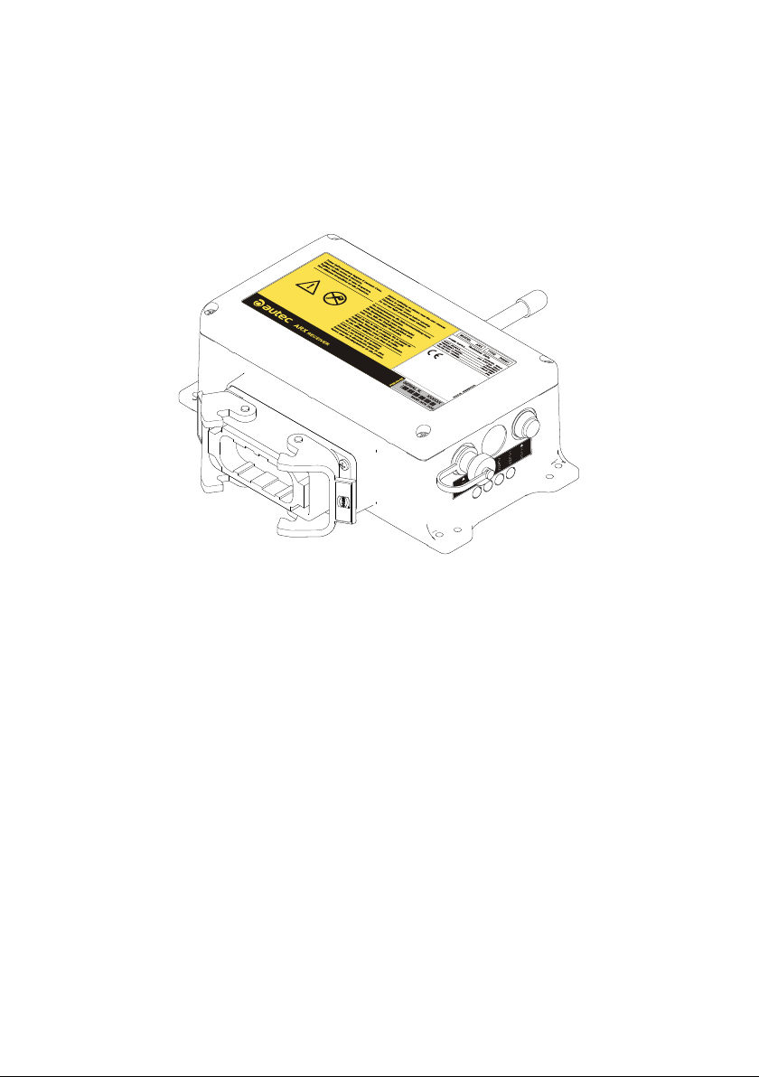
1 Description
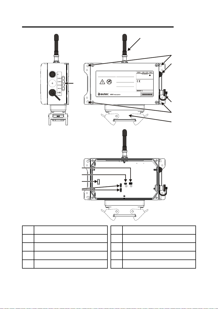
Description
A LEDs
B antenna
C mounting holes
D TEACH pushbutton
E connector for cable control
LIARXE00-00
F plug
G DTK connector (for memory board)
H IDK (for address key)
J fuse F1
K DIP switches
AUTEC - Dynamic Series
Technical data 3
The receiving unit communicates with the machine thruough the output and the corresponding
wiring.
1.1 Safety functions of the ARX receiving unit
The SO1 and SO2 outputs may be either STOP (stop function) or SAFETY outputs (UMFS
function), according to the conguration of the receiving unit (see technical data sheet).
If thet are congured as STOP outputs the UMFS safety function is not available.
If they are congured as SAFETY outputs both the UMFS and stop safety functions are
available.
2 Technical data
Power supply ........................................................................................................ 8-30V
Antenna .............................................................................................................. dedicated
Rated current of the SO1 and SO2 outputs ..................................................... 2A (30V )
Rated current of digital outputs ........................................................................ 2A (30V )
Rated current of analogue outputs (PWM) ....................................................... 2A (30V )
Rated current of analogue outputs (voltage) ............................................... 10mA (28V )
Protection of outputs (fuse F1) ....................................................... 10A (32V , autofuse)
Housing material .......................................................................................... PA6 (20% fg)
Protection degree ....................................................................................... IP66 (NEMA 4)
Dimensions ................................................................ 202x123x83mm (7.95x4.84x3.23In)
Weight ........................................................................................................... 1.2kg (2.7Lb)
3 Technical data sheet
The technical data sheet contains the wiring diagram showing the connection between the
receiving unit and the machine. It also contains the transmitting unit conguration and shows
the matching between commands sent and machine functions/movements.
Each technical data sheet must be lled in, checked and signed by the installer, who is
responsible for a correct wiring.
A copy of the technical data sheet must always be kept together with this manual (always
keep a copy of this data sheet for administrative purposes).
The wiring of the receiving unit outputs must always reect the wiring
indicated in the technical data sheet.
AUTEC - Dynamic Series
LIARXE00-00
4
4 Plates
The receiving unit has the following plates:
Plate Position Content
radio remote control
identication plate
technical data plate
On the cover of the
receiving unit
On the cover of the
receiving unit
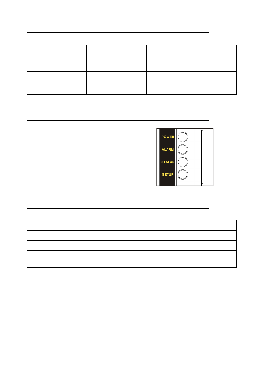
5 Light signals
The receiving unit ARX has four LEDs:
- POWER is green
- ALARM is red
- STATUS is blue
- SETUP is yellow
Plates
Radio remote control serial number
(S/N), bar code and manufacturing year.
MODEL, TYPE and main receiving unit
technical data, marking and possible
radio remote control marks.
5.1 POWER LED (green)
The POWER LED indicates the status of the receiving unit and of the radio link.
The POWER LED... Meaning
…is o The receiving unit is switched o.
...is on The receiving unit is powered and there is no radio link.
… blinks
LIARXE00-00
The receiving unit is powered and radio link has been
built.
AUTEC - Dynamic Series
 Loading...