

Page 1
Page 2

Operation Manual
E4P
E4.01.02
Issue date: 15.Nov.2016
Page: Intro 1
Revision no: 1
– Intentionally left blank –
Page 3

Operation Manual
E4P
E4.01.02
Issue date: 15.Nov.2016
Page: Intro 2
Revision no: 1
Date: Wiener Neustadt, 15.Nov.2016
Author: Austro Engine GmbH
Rudolf – Diesel – Straße – 11
A-2700 Wiener Neustadt
Document number: E4.01.02
Revision: 1
Page 4

Operation Manual
E4P
E4.01.02
Issue date: 15.Nov.2016
Page: Intro 3
Revision no: 1
– Intentionally left blank –
Page 5

Operation Manual
E4P
E4.01.02
Issue date: 15.Nov.2016
Page: 0-1
Revision no: 1
0 Index
0 Index ................................................................................................... 0-1
1 Identification ....................................................................................... 1-1
1.1 Type Designation .......................................................................................... 1-1
1.2 Engine Identification ..................................................................................... 1-1
1.3 Record of Revision ........................................................................................ 1-2
1.3.1 List of Revision ................................................................................................... 1-3
1.3.2 List of incorporated Temporary Revisions ............................................................. 1-4
1.4 Design Holder .............................................................................................. 1-5
1.5 Manufacturer ............................................................................................... 1-5
1.6 List of Abbreviations ..................................................................................... 1-6
2 General Information ............................................................................ 2-1
2.1 Description and Using ................................................................................... 2-1
2.2 Safety .......................................................................................................... 2-2
2.3 Safety Information ........................................................................................ 2-2
2.4 Dimension and Volume ................................................................................. 2-3
2.5 Technical Data Sheet for E4P Engine .............................................................. 2-4
2.5.1 Engine Performance ............................................................................................ 2-4
2.5.2 High power performance ..................................................................................... 2-5
2.5.3 Fuel consumption ............................................................................................... 2-6
2.5.4 Propeller Setpoint Curve ...................................................................................... 2-6
2.5.5 Engine and Gearbox Data Sheet .......................................................................... 2-7
2.5.6 Limitation Section ............................................................................................... 2-8
2.5.6.1 Oil .............................................................................................................. 2-8
2.5.6.2 Coolant ....................................................................................................... 2-9
2.5.6.3 Fuel ........................................................................................................... 2-10
2.5.6.4 Fuel Grade ................................................................................................. 2-10
2.5.6.5 Speed ........................................................................................................ 2-11
2.5.6.6 Voltage ...................................................................................................... 2-11
2.5.6.7 Performance ............................................................................................... 2-11
2.5.7 Information Section ........................................................................................... 2-12
2.5.7.1 Engine Oil .................................................................................................. 2-12
2.5.7.2 Coolant ...................................................................................................... 2-12
2.5.7.3 Fuel ........................................................................................................... 2-12
2.5.8 Operating Envelope ........................................................................................... 2-13
3 Delivery, Storage and Standstill Period .............................................. 3-1
3.1 Delivery ....................................................................................................... 3-1
3.2 Storage up to 6 months ................................................................................ 3-1
3.3 Storage over 6 months .................................................................................. 3-1
3.4 Engine depreservation .................................................................................. 3-1
3.5 Standstill Period ........................................................................................... 3-2
4 Operating Instructions ........................................................................ 4-1
4.1 Engine Start Procedure ................................................................................. 4-1
4.1.1 Pre-Start Inspection ............................................................................................ 4-1
4.1.2 Engine Start ....................................................................................................... 4-2
4.1.3 Warm Up ........................................................................................................... 4-2
4.1.4 Before Take-off Check ......................................................................................... 4-3
4.1.5 During Flight Check ............................................................................................ 4-3
4.1.6 Engine OFF ........................................................................................................ 4-3
4.2 Low Oil Pressure ........................................................................................... 4-3
4.3 Restart in flight ............................................................................................ 4-4
4.3.1 Restart of engine by starter ................................................................................. 4-4
Page 6

Operation Manual
E4P
E4.01.02
Issue date: 15.Nov.2016
Page: 0-2
Revision no: 1
5 Emergency Procedures ........................................................................ 5-1
5.1 Power loss and abnormal engine behaviour .................................................... 5-1
5.2 Low Oil Pressure ........................................................................................... 5-1
5.3 High Oil Temperature.................................................................................... 5-1
5.4 High Gearbox Oil Temperature....................................................................... 5-1
5.5 Low fuel pressure ......................................................................................... 5-2
5.6 High Fuel Temperature ................................................................................. 5-2
5.7 High Coolant Temperature ............................................................................ 5-2
5.8 Engine Fire .................................................................................................. 5-2
5.9 Electric power supply out of range ................................................................. 5-2
5.9.1 Restart of engine by windmilling .......................................................................... 5-2
6 System Description .............................................................................. 6-1
6.1 Intake System .............................................................................................. 6-1
6.2 Exhaust System ............................................................................................ 6-1
6.3 Fuel System ................................................................................................. 6-2
6.4 Coolant System ............................................................................................ 6-3
6.4.1 Standard Coolant System .................................................................................... 6-3
6.4.2 Coolant System with optional Gearbox Oil Cooler .................................................. 6-4
6.5 Lubricating System ....................................................................................... 6-5
6.6 Electrical System .......................................................................................... 6-6
6.6.1 EECU Functions .................................................................................................. 6-8
6.6.2 Engine Speed and Power Regulation ................................................................... 6-12
6.6.3 Error Handling ................................................................................................... 6-14
6.6.3.1 Description of ECU Switch Over ................................................................... 6-14
6.6.3.2 Resetting ECU caution in Operation ............................................................. 6-15
6.6.3.3 Caution Handling Table Software VC33_0_05_18_pre1 ................................. 6-16
7 Additional Information ........................................................................ 7-1
7.1 Propeller Self Test (Automatic Run-Up Test) ................................................... 7-1
Page 7
Operation Manual
E4P
E4.01.02
Issue date: 15.Nov.2016
Page: 1-1
Revision no: 1
1 Identification
1.1 Type Designation
TC-Designation: E4
Model: E4P (Sales Name AE330)
For detailed information about available configurations refer to latest revision of Austro Engine Service
Bulletin MSB E4-002.
If not otherwise stated this manual is applicable to all available configurations.
1.2 Engine Identification
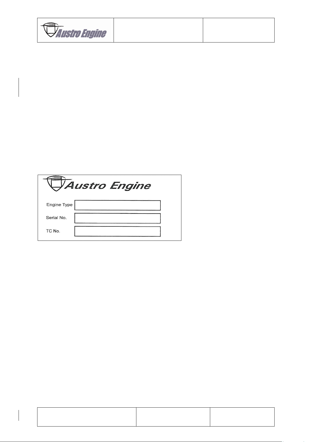
Relevant data for engine identification including the serial number is stated on an engine identification
plate, which is fixed onto the crankcase beneath the starter. For further questions contact Austro
Engine GmbH.
Fig. 1.1: Engine Identification plate
Page 8

Operation Manual
E4P
E4.01.02
Issue date: 15.Nov.2016
Page: 1-2
Revision no: 1
1.3 Record of Revision
All revisions of this manual are recorded in chapter “List of Revisions”.
All incorporated temporary revisions are recorded in chapter “List of incorporated Temporary Revisions”.
New or amended text is indicated by a vertical black line at the left hand side of the revised page, with
the revision number and date appearing at the bottom of the page.
Cover pages of temporary revisions are inserted in front the cover page of this manual. The other pages
of temporary revisions are inserted adjacent to or in front of the corresponding OM pages.
Temporary revisions are used to provide information on systems or equipment until the next ‘permanent’
revision of the Engine Manual.
It is the responsibility of the installer to ensure that this manual is maintained to a current status.
If the address or the ownership of the engine/aircraft changes, an address card has to be sent to Austro
Engines GmbH.
Page 9

Operation Manual
E4P
E4.01.02
Issue date: 15.Nov.2016
Page: 1-3
Revision no: 1
1.3.1 List of Revision
Re.
No.
Reason
Chapter(s)
Page(s)
Date of
Revision
Approval /
Date
0
First Release
All
All
26.Mar.2015
EASA /
26.Mar.2015
1
MDC-E4-377
All
All
15.Nov.2016
EASA /
29.Nov.2016
*) The technical content of this document is approved under the authority of DOA ref. EASA.21J.0399
Page 10
Operation Manual
E4P
E4.01.02
Issue date: 15.Nov.2016
Page: 1-4
Revision no: 1
1.3.2 List of incorporated Temporary Revisions
Temporary Revision Number
Title of Temporary Revision
Incorporated with
Manual Rev.
OM-TR-MDC-E4-217d
Engine preservation
1
OM-TR-MDC-E4-359b
EECU Software VC33_x_05_19
1
OM-TR-MDC-E4-378
TBO extension of engine components
1
OM-TR-MDC-E4-382
EECU Software VC33_x_05_20
1
OM-TR-ODC-E4-008
Gearbox Oil Cooler
1
Page 11

Operation Manual
E4P
E4.01.02
Issue date: 15.Nov.2016
Page: 1-5
Revision no: 1
1.4 Design Holder
Austro Engine GmbH
Rudolf – Diesel – Straße 11
A-2700 Wiener Neustadt
DOA No.: EASO.21J.399
1.5 Manufacturer
Austro Engine GmbH
Rudolf – Diesel – Straße 11
A-2700 Wiener Neustadt
EASA POA No.: AT.21G.0010
Page 12
Operation Manual
E4P
E4.01.02
Issue date: 15.Nov.2016
Page: 1-6
Revision no: 1
1.6 List of Abbreviations
AE
Austro Engine
BATT
Battery
CAD
Computer Aided Design
CAN
Controller Area Network
CCW
Counter-Clockwise
CPC
Connector Type
CS
Certification Specification
DOHC
Double Overhead Camshaft
EECS
Electronic Engine Control System
EECU
Electronic Engine Control Unit
ECU
Electronic Control Unit
EMI
Electromagnetic Interference
EPC
Electric Pneumatic Converter
ESD
Electrostatic Sensitive Device
FAR
Federal Aviation Regulations
GND
Ground
GPC
Glow Plug Control Unit
HIRF
High Intensity Radiated Field
HPP
High Pressure Pump
MBN
Mercedes Benz Norm
MDC
Mandatory Design Change
ODC
Optional Design Change
RPM
Revolutions Per Minute
SW
Soft Ware
TDD
Type Design Definition
TC
Turbo Charger
Ubatt
Battery Voltage
Page 13
Operation Manual
E4P
E4.01.02
Issue date: 15.Nov.2016
Page: 2-1
Revision no: 1
2 General Information
In the present Operation Manual the proper operation of the aircraft engine E4P is documented.
With the publication of the Operation Manual Austro Engine GmbH ensures the correctness of the
instructions. In case of changes Austro Engine GmbH will inform with Service Bulletins, Service Letters
or manual amendments, if it is necessary.
In case of problems with the engine operation or any further questions about the engine,
contact Austro Engine GmbH.
The following symbols and warning signs are used in the manual to point out important instructions.
They must be heeded strictly to prevent personal injury and material damage, to insure operational
safety of the aircraft and to avoid any damage to the aircraft as a result of incorrect handling.
Warning: Disregarding these safety rules can cause personal injury or even death.
Caution: Disregarding these special instructions and safety measures can damage the
engine or other components.
Note: Additional not or instruction for better understanding of an instruction.
2.1 Description and Using
The E4P is a liquid-cooled, in-line four-stroke four cylinder engine with a double overhead camshaft
(DOHC) with four valves per cylinder. The valves are actuated by the cam follower
The direct fuel injection is realized by means of a common rail technique and the engine is charged by
a turbo charger in combination with an intercooler.
The propeller is activated by a directly integrated gearbox with an integral torsional vibration damper.
All engine components are controlled by an EECU system.
● This engine is only designed for pull propeller installations.
● The engine should not be operated without propeller.
● Only useable in aircraft.
● It is not capable for aerobatics use
● It is not allowed to run the engine without the specified quality and quantity of fluids.
● Only the use of recommended equipment and fluids grants a save run of the engine.
Page 14

Operation Manual
E4P
E4.01.02
Issue date: 15.Nov.2016
Page: 2-2
Revision no: 1
2.2 Safety
The required provisions of the employer’s liability insurance organization and the other relevant safety
rules, like for example the trade supervision authority have to be kept in mind.
The described work steps, contained in this Operation Manual have to be performed only by trained,
qualified persons and / or specialized companies, with a current and valid license from the aviation
authority to do such work
For further information the national aviation authority has to be contacted.
2.3 Safety Information
● To prevent personal injury and damage secure all tools before starting the engine.
● The pertinent accident prevention regulations as well as other commonly accepted safety,
occupational health and air traffic legal requirements must be observed.
● Operators must also observe any additional regulations and requirements which are applicable
in their territory.
● The engine has to be protected against contamination and potentially hazardous manipulation.
● Rotation of the propeller by hand is not recommended.
Page 15
Operation Manual
E4P
E4.01.02
Issue date: 15.Nov.2016
Page: 2-3
Revision no: 1
2.4 Dimension and Volume
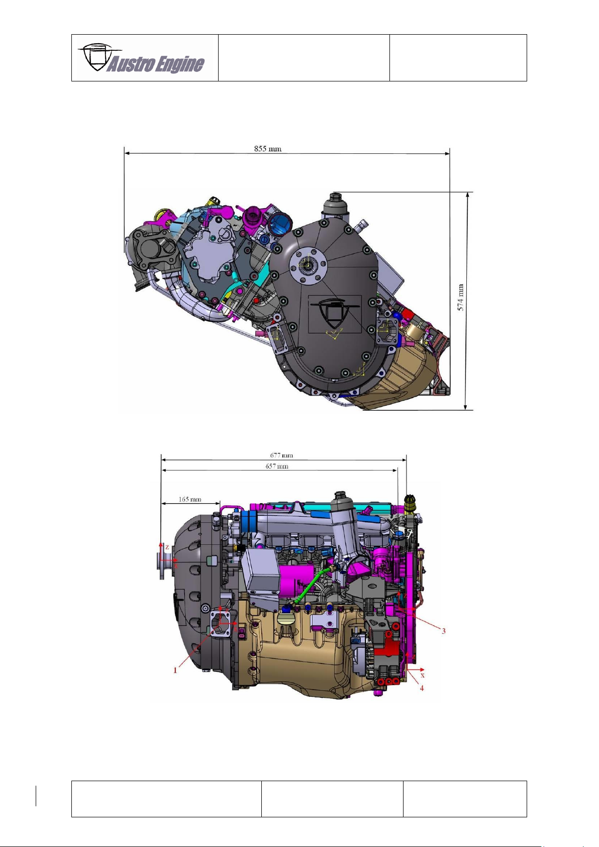
For further information about measurements refer to the Installation Manual of the E4 series (Doc. No.:
E4.02.01).
Fig. 2.1: Engine view
Fig. 2.2: Engine view
Page 16
Operation Manual
E4P
E4.01.02
Issue date: 15.Nov.2016
Page: 2-4
Revision no: 1
2.5 Technical Data Sheet for E4P Engine
All speed information’s refer to the revolution speed of the propeller. The revolution speed of the engine
is declared separately.
For detailed manifold data and dimensions refer to the “Installation Manual” of the E4 engine (Doc. No.:
E4.02.01).
2.5.1 Engine Performance
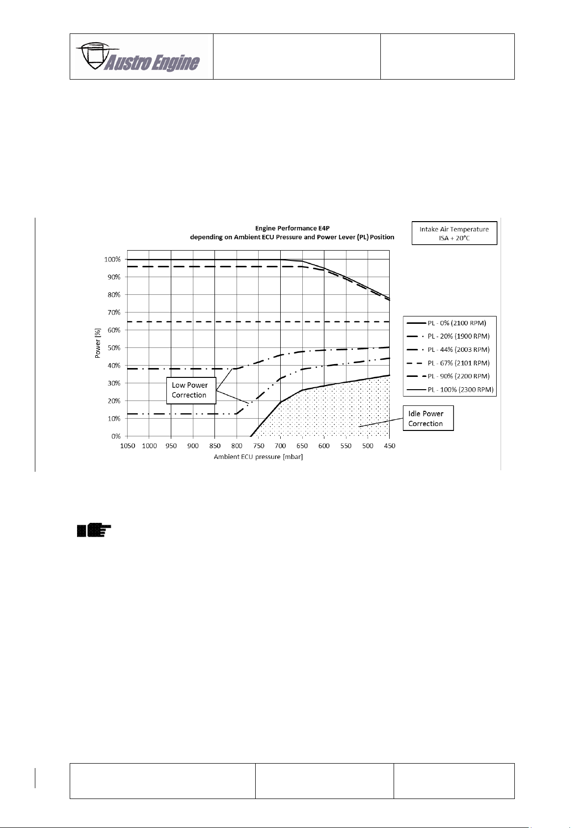
Fig. 2.3: Engine Performance
Low and Idle Power Correction
Below 850 mbar ambient ECU pressure the low power output is increased and below 800
mbar ECU pressure the idle power output is increased regarding to the desired power
(power lever position) to prevent the engine from combustion extinction.
Page 17
Operation Manual
E4P
E4.01.02
Issue date: 15.Nov.2016
Page: 2-5
Revision no: 1
2.5.2 High power performance
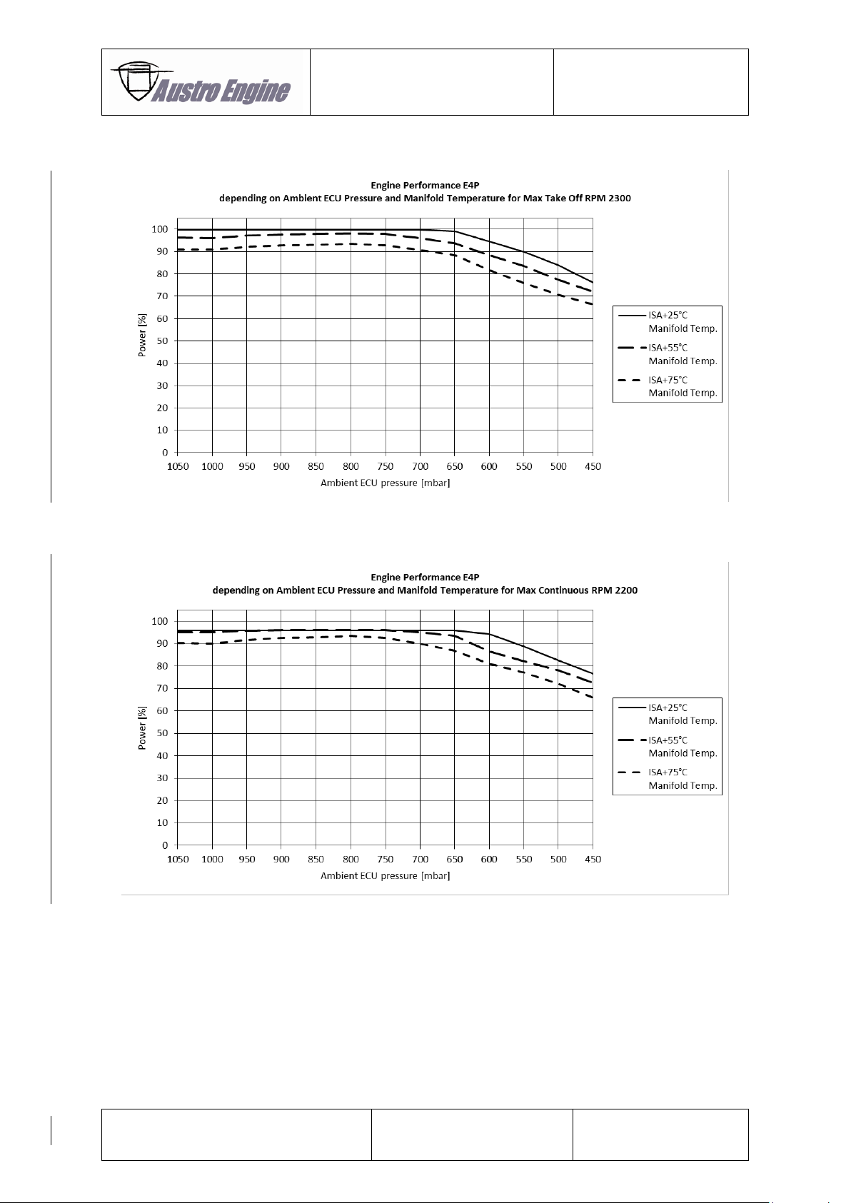
Fig. 2.4: Power Curve RPM 2300
Fig. 2.5: Power Curve RPM 2200
Rated Power (100%):
132 kW
(177,0 hp)
Page 18
Operation Manual
E4P
E4.01.02
Issue date: 15.Nov.2016
Page: 2-6
Revision no: 1
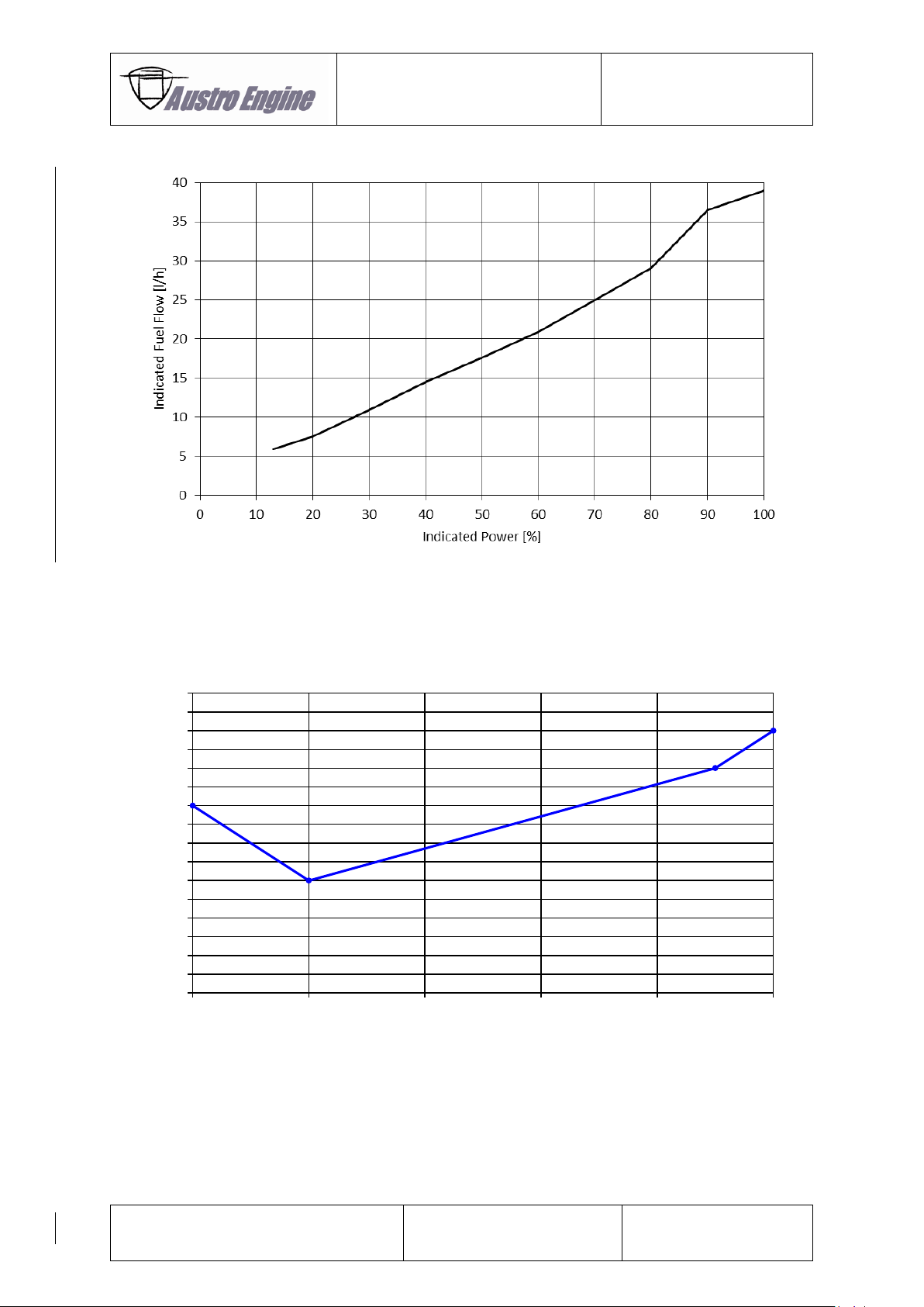
2.5.3 Fuel consumption
Fig. 2.6: Fuel consumption
2.5.4 Propeller Setpoint Curve
Fig. 2.7: Propeller Setpoint Curve E4P
The propeller setpoint is set on the governor by the EECS on the basis of power lever position. This
propeller speed (rpm) is held at any airspeed as long as the propeller is within the range of stops.
0%
20%
90%
100%
1600
1650
1700
1750
1800
1850
1900
1950
2000
2050
2100
2150
2200
2250
2300
2350
2400
0% 20% 40% 60% 80% 100%
Propeller Speed [rpm]
Power Lever [%]
Propeller Setpoint Curve E4P
Page 19

Operation Manual
E4P
E4.01.02
Issue date: 15.Nov.2016
Page: 2-7
Revision no: 1
2.5.5 Engine and Gearbox Data Sheet
Max. take-off power (max. 5 min.):
132 kW
Max. continuous power:
126 kW
Max. recommended cruising power:
93,8 kW
Max. prop. Over speed:
2500 rpm
Max. take-off speed:
2300 rpm
Max. continuous speed:
2200 rpm
Max. recommended cruising speed:
2123 rpm
Idling prop speed:
710 rpm
Gearbox ratio:
I = 1.69
Page 20

Operation Manual
E4P
E4.01.02
Issue date: 15.Nov.2016
Page: 2-8
Revision no: 1
2.5.6 Limitation Section
All temperature and pressure limits must not be exceeded. The limits have to be
shown to the pilot in a red range.
2.5.6.1 Oil
Oil temperature (start):
min.
-30 ºC
(-22 ºF)
Oil temperature
max.
139 ºC
(282 ºF)
Oil pressure:
at idle
min.
0,9 bar
(21.75 psi)
(at max. cont. conditions)
min.
2.5 bar
(36.26 psi)
max.
6.5 bar
(94.25 psi)
Approved engine oil types:
Brand name
SAE Grade
AUSTRO ENGINE Aero
recommended by Austro Engine GmbH
5W-40
CASTROL Edge Professional A3
5W-40
CASTROL Magnatec Professional A3
5W-40
GULF Formula GX
5W-40
LIQUI MOLY Leichtlauf High Tech
5W-40
LUKOIL Luxe synthetic
5W-40
MEGOL Motorenoel High Condition
5W-40
SHELL Helix Ultra
5W-40
VALVOLINE SynPower HST
5W-40
AEROSHELL Oil Diesel Ultra
5W-30
ADDINOL Super Power MV 0537
5W-30
BP Visco 5000
5W-30
CASTROL Edge 5W-30 A3
5W-30
CASTROL Edge Professional A3
5W-30
G-ENERGY F Synth
5W-30
GULF Formula GMX
5W-30
REPSOL Elite Common Rail
5W-30
SHELL Helix Ultra
5W-30
Table to be continued on the next page!
Page 21
Operation Manual
E4P
E4.01.02
Issue date: 15.Nov.2016
Page: 2-9
Revision no: 1
Brand name
SAE Grade
TOTAL Quartz 9000 Energy
5W-30
CASTROl Edge 0W-40 A3/B4
0W-40
CASTROL Edge Professional A3
0W-40
SHELL Helix Ultra
0W-40
Only use above listed engine oils for operation if conformance to MB 229.5 specification is
ensured (e.g. by label on the oil packaging). Austro Engine GmbH will not assume any
liabilities if other sorts of oil are used.
It is not recommended to mix different SAE grades.
Use only one type of approved E4P engine oil for an oil change.
Oil brands which are not approved must not be used.
Oil volume (initial filling)
7.5 l
Oil volume (continuously)
min.
5 l
max.
7 l
Gearbox oil temperature (start):
min.
-30 ºC
(-22 ºF)
Gearbox oil temperature (full load)
min.
35 ºC
(95 °F)
max.
120 ºC
(248 ºF)
Gearbox oil type:
SHELL Spirax S6 GXME 75W-80
(former brand name: SHELL Spirax GSX 75W-80)
Gearbox oil volume
2,3 l
Refer to MM for proper filling procedure.
2.5.6.2 Coolant
Coolant temperature (start):
min.
-30 ºC
(-22ºF)
Coolant temperature (full load)
min.
60 ºC
(140 ºF)
Coolant temperature
max.
100 ºC
(212 ºF)
It has to be ensured that the freezing point of the coolant is at or below -30 ºC before
operating the engine.
Page 22

Operation Manual
E4P
E4.01.02
Issue date: 15.Nov.2016
Page: 2-10
Revision no: 1
2.5.6.3 Fuel
Operation with Kerosene:
Fuel temperature at HPP:
during operation
min.
-30 ºC
(-22 ºF)
max.
60 ºC
(140 ºF)
If the fuel temperature is below -30 ºC (-22 ºF), the fuel has to be warmed.
2.5.6.4 Fuel Grade
Kerosene
Jet A, Jet A – 1 (ASTM D 1655)
TS-1 (Russia; GOST 10227-86)
TS-1 (Ukraine, GSTU 320.00149943.011-99)
RT (Russia; GOST 10227-86)
RT (Ukraine; GSTU 320.00149943.007-97)
No. 3 Jet Fuel (China; GB 6537-2006)
JP-8 (F34) (USA, MIL-DTL-83133G-2010)
OPERATION WITH ANTI-MICROBIAL LIFE FUEL ADDITIVES:
The applications of the following additives are allowed for an operated engine:
KATHON FP 1.5:
max. 100 ppm
BIOBOR JF:
max. 270 ppm
Any mixture of the different types of additives is not permitted.
Both specified brands of additive are qualified for the operation with the certified fuel
grades for the E4P engine.
To clean the fuel system of the aircraft a higher dosage of the specified additive is allowed
under consideration of the instructions of the additive manufacturer. During cleaning the
engine must not be operated.
In case of an unknown or an over dosage with the additives the fuel system have to be
purged until the dosage is within the allowed limits.
Page 23
Operation Manual
E4P
E4.01.02
Issue date: 15.Nov.2016
Page: 2-11
Revision no: 1
OPERATION WITH ANTI-ICING FUEL ADDITIVES:
The application of the following additive is allowed for an operated engine:
PRIST Hi-Flash
max. 1500 ppm
“I-M” (acc. to OST 54-3-175-72-99)
max. 3000 ppm
Any mixture of the different types of additives is not permitted.
PRIST Hi-Flash anti-icing fuel additive is only allowed for operation with Jet A, Jet A-1
(ASTM D 1655) and JP-8 (F34).
Anti-icing fuel additive “I-M” is only allowed for operation with TS-1 (Russia and Ukraine)
and RT (Russia and Ukraine).
If operating the engine with above listed anti-icing fuel additives, the specifications of the
manufacturers must be adhered to.
2.5.6.5 Speed
Max. prop. over speed:
2500 rpm
Max. take-off speed:
2300 rpm
Max. continuous speed:
2200 rpm
2.5.6.6 Voltage
min.
20,5 V
max.
32,2 V
2.5.6.7 Performance
Certified Altitude
max.
20.000 ft
Intentional negative g operation is not allowed.
Page 24

Operation Manual
E4P
E4.01.02
Issue date: 15.Nov.2016
Page: 2-12
Revision no: 1
2.5.7 Information Section
The pressure and temperature in the information section are the optimum of the E4P
engine and should be kept in mind. The range between the limits and the optimum can be
indicated yellow. For a better overview the optimum can be shown in a green range.
2.5.7.1 Engine Oil
Optimum operating oil temperature:
min.
60 ºC
(140 ºF)
max.
135 ºC
(275 ºF)
Optimum operating oil pressure:
min.
4.0 bar
(n = 1700 – 2300 rpm)
(58 psi)
max.
4.9 bar
(71 psi)
Oil consumption:
< 0.1 l/h
2.5.7.2 Coolant
Coolant temperature (optimum)
min.
60 ºC
(140 ºF)
max.
95 ºC
(203 ºF)
Coolant:
Water / radiator protection
mixed at ratio with a minimum of 50% radiator protection
Recommended radiator protection type:
Glysantin G 48 Protect Plus
Water specification:
Only use distilled water for mixing ratio
2.5.7.3 Fuel
Fuel inlet temperature at HPP (take-off power):
optimum:
<50 ºC
(<122 ºF)
Page 25
Operation Manual
E4P
E4.01.02
Issue date: 15.Nov.2016
Page: 2-13
Revision no: 1
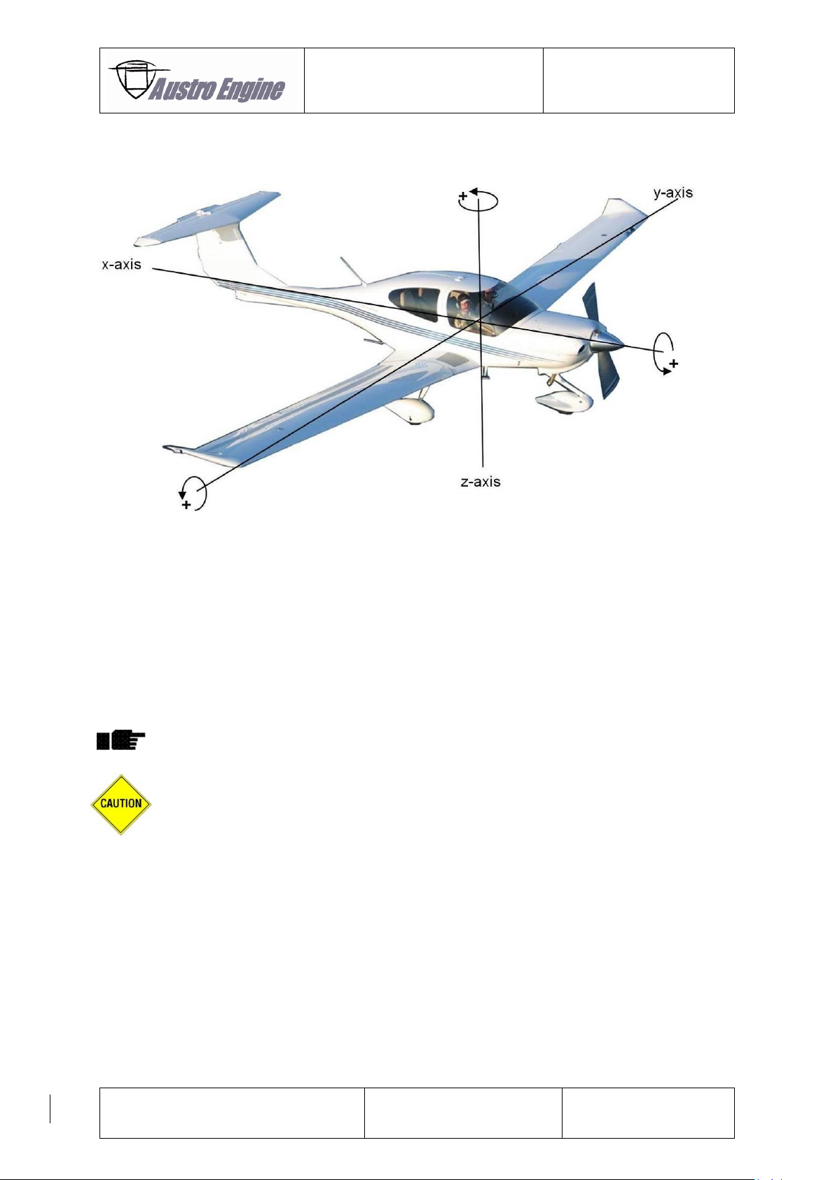
2.5.8 Operating Envelope
Fig. 2.8: Banking Rotation
Banking rotation deviations from the apparent perpendicular:
Around the x - axis:
max.
±15 º
Around the y - axis
max.
-35 º / + 25 º
Around the z - axis
max.
±20 º
Up to these deviations from the apparent perpendicular, proper lubrication is ensured.
Intentional negative g operation is not permitted.
Intentional negative g operation can lead to low oil pressure and subsequently to turbo
charger damage.
Page 26

Operation Manual
E4P
E4.01.02
Issue date: 15.Nov.2016
Page: 2-14
Revision no: 1
– Intentionally left blank –
Page 27
Operation Manual
E4P
E4.01.02
Issue date: 15.Nov.2016
Page: 3-1
Revision no: 1
3 Delivery, Storage and Standstill Period
3.1 Delivery
The engine is delivered in a wooden box and is preserved for a distinct time. For details about
preservation refer to shipping documents (e.g. engine log).
The preservation is only guaranteed if the yellow protective bag, in which the engine is
wrapped up, is not damaged or broken.
3.2 Storage up to 6 months
This procedure is only applicable for an engine, which is installed.
Perform an engine oil and filter change according to Maintenance Manual E4.08.04
Add a volatile corrosion inhibitor (VCI) lubricating liquid as a concentrate (e.g. FUCHS
ANTICORIT VCI UNI O 40) to the engine oil.
Refer to the product data sheet for the determination of the appropriate quantity. The
volume, which needs to be protected, is 10 litres or 0.01 cubic metres.
Check coolant level – if necessary correct the coolant level.
Ground run:
- Warm up the engine according to chapter 4.1.2 and chapter 4.1.3
- 100% load until 100 °C (212 °F) oil temperature.
- 1 minute 100% load.
- 1 minute idle power.
- Shut down.
Relieve V-belt tension – refer to Maintenance Manual E4.08.04 performing steps 1 and 2 of the
relevant chapter
Close engine openings airproof.
The engine must not be started after V-belt tension relieve.
3.3 Storage over 6 months
Contact engine manufacturer Austro Engine GmbH.
3.4 Engine depreservation
Remove all covers from engine openings
Install V-belt – refer to Maintenance Manual E4.08.04
Perform an engine ground run according to chapter 3.2
Page 28

Operation Manual
E4P
E4.01.02
Issue date: 15.Nov.2016
Page: 3-2
Revision no: 1
3.5 Standstill Period
If the engine is installed already and it is not intended to operate the engine for a longer time, the
following is required:
Above -30°C:
Maximum allowed standstill period: 4 weeks
The following procedure has to be performed:
Engine Start and Warm Up according to chapter 4.1.2 and chapter 4.1.3.
100% load until 100 ºC (212 ºF) oil temperature.
1 minute 100% load.
1 minute idle power.
Shut down.
Between -30°C and -53°C:
Maximum allowed standstill period: 2 weeks
The following procedure has to be performed:
In case of prolonged temperatures below -38°C change water / radiator protection mixture ratio
to 40:60.
Warm up engine compartment without engine running till oil, gearbox and coolant temperature
indicates temperatures above -30°C.
The V-belt and sealing rings may suffer serious damage when operating the engine without
prior warm up.
Engine Start and Warm Up according to chapter 4.1.2 and chapter 4.1.3.
Non-compliance with chapter 2.5.6.3 is acceptable during ground run only.
Run engine for approx. 30 min. at engine fluid temperatures within normal range.
1 minute 100% load.
1 minute idle power.
Shut down.
Page 29
Operation Manual
E4P
E4.01.02
Issue date: 15.Nov.2016
Page: 4-1
Revision no: 1
4 Operating Instructions
These operating instructions are for the using of the E4P engine. For more information about the flight
operation the manufacturer of the aircraft has to be contacted.
Only authorised persons who hold a valid license are allowed to execute the following
steps.
4.1 Engine Start Procedure
Further information of the A/C start procedure refer to the manual of the aircraft manufacturer.
For safety reasons the engine start must only be performed in a secure and safe area
protected for unauthorized persons. The start must only be executed by persons with a
valid license of an aviation authority.
The start procedure is only for the straight engine function.
4.1.1 Pre-Start Inspection
Check Fuel Quantity
Check Fuel Temperature
Check Air Inlets / Outlets for blockage
Check Engine Oil Level
Check Gearbox Oil Level
Check Breather Outlet for blockage
Check for Oil leakage
Check exhaust pipe for oil leakage from the turbo charger
Check for Fuel leakage
Check for Coolant leakage
Drain Water of the fuel system (for drain position refer to the aircraft flight manual)
Page 30
Operation Manual
E4P
E4.01.02
Issue date: 15.Nov.2016
Page: 4-2
Revision no: 1
4.1.2 Engine Start
1. Engine Master – “ON”
2. Glow plug lights – “ON”
3. Glow plugs – „OFF“ (the glow plug lights extinguish after not more than 15 seconds)
4. Propeller Area – Clear and Save
5. Engine – “Start”
Do not operate the starter for more than 10 seconds.
At ambient temperatures below -22°C it is possible that the engine will not run at the first
attempt. In this case wait 60 seconds between the start attempts.
6. Oil Pressure rise within 3 seconds
7. Voltage, Electric Load – Check indication
8. Alternator switch – “ON”
The alternator switch should not be turned ON before starting the engine. Turning the
alternator switch ON while the engine is not running reduces the service life of the
alternator system and drains the battery unnecessarily.
4.1.3 Warm Up
1. Oil Pressure – “CHECKED” (refer to chapter 2.5.6.1 and 2.5.7.1)
2. rpm (Propeller) – “CHECKED” 710 +/- 30 rpm
3. Idle – 30 seconds
4. Thereafter power as required, max. 50 % load until oil temperature >50 ºC (> 122 ºF) and
coolant temperature >60 ºC (> 140 ºF) and Gearbox Oil temperature >35 ºC (> 95 ºF).
At low oil temperature high oil pressure may occur which could lead to an oil pressure
warning. In this case reduce power setting until the caution disappears and conduct the
warm up with this reduced setting.
At low gearbox oil temperature it may occur that the ECU-Self Test is not performed
successfully. In this case warm up the engine and retry the ECU-Self Test at higher gearbox
temperatures.
Page 31
Operation Manual
E4P
E4.01.02
Issue date: 15.Nov.2016
Page: 4-3
Revision no: 1
4.1.4 Before Take-off Check
1. Engine Instruments – CHECKED
2. Fuel Temperature – CHECKED (refer to chapter 2.5.6.3 and 2.5.7.3 Fuel)
3. Power Levers – “IDLE”
4. ECU-Self Test – PERFORM
The ECU cockpit switch (voter switch) must remain in the “Auto”-Position throughout the
whole self test procedure. Manually selecting ECU “A” or “B” prevents the self test from
successfully testing the switch-over functionality causing the self test to abort with an error
indication (“ECU Caution”-Lamp will remain ON).
5. Power Lever Max (100% / 10 sec) – CHECK LOAD, CHECK RPM, CHECK Fuel Flow
4.1.5 During Flight Check
Engine/propeller speed and all temperatures and pressure must be monitored constantly during flight.
For operation optimums refer to chapter 2.5.
4.1.6 Engine OFF
The engine has to run for minimum 1 minute at maximum 10% of full load, before shut down.
After turning the engine master OFF, wait until 20 sec. before turning the battery master
OFF unless otherwise defined in the aircraft flight manual. This ensures that engine and
flight data can be written to non-volatile memory before removing power.
4.2 Low Oil Pressure
It may occur that operation of the engine after landing at idle speed and high oil temperature leads
to a low oil pressure warning. If this is the case push the power lever forward until the caution
disappears.
Page 32

Operation Manual
E4P
E4.01.02
Issue date: 15.Nov.2016
Page: 4-4
Revision no: 1
4.3 Restart in flight
It is not recommended to shut-off a servicable engine in flight for any reason.
The following procedure is recommended to restart an engine in flight:
In case of an engine malfunction determine the root cause and only continue in case a safe
restart is possible.
1. Max. demonstrated altitude for immediate restart by starter: 15.000ft
2. Max. demonstrated altitude for restart after 10 min. and ambient air temperature higher than
ISA by starter: 10.000ft
3. Max. demonstrated altitude for restart after 5 min. and ambient air temperature between ISA
and ISA minus 10 °C by starter: 10.000ft
4. Max. demonstrated altitude for restart after 2 min. and ambient air temperature below ISA
minus 10 °C by starter: 10.000ft
5. Airspeed: see applicable Aircraft Flight Manual
6. Power Levers – “IDLE”
7. Engine Master – “ON”
8. Engage starter of engine (Key).
Move power lever slightly forward to a power rating assuring that the referring engine is
delivering thrust, as a rotating propeller is not a guarantee for a running engine.
Page 33

Operation Manual
E4P
E4.01.02
Issue date: 15.Nov.2016
Page: 5-1
Revision no: 1
5 Emergency Procedures
5.1 Power loss and abnormal engine behaviour
● Power lever “FULL FORWARD”
● Select the fuel tank with sufficient fuel level.
● Continue engine operation
● If abnormal engine behavior is still evident land as soon as possible
In case of electrical failures in power generation the internal EECU voter switches automatically to the
ECU which provides the better engine performance.
In case of doubt the automatic decision can be overruled manually by switching to the
ECU A or ECU B voter position. If the manual override does not provide a better performance it is
strongly recommended to switch back to the automatic voter position.
Depending on the failure it is possible that the EECU uses default values for further operation. Refer to
chapter 6.6.3 for detailed error handling information.
5.2 Low Oil Pressure
● Power lever “FULL FORWARD”
● if the oil pressure rises into green continue operation in the green range
● if the oil pressure remains low Power Lever “IDLE”
● Land as soon as possible
● expect sudden engine stoppage
5.3 High Oil Temperature
● Reduce power
● Monitor oil temperature
● Land as soon as possible
5.4 High Gearbox Oil Temperature
● Reduce power
● Monitor oil temperature
● Increase gearbox cooling by e.g. increase airspeed
● Land as soon as possible
Page 34
Operation Manual
E4P
E4.01.02
Issue date: 15.Nov.2016
Page: 5-2
Revision no: 1
5.5 Low fuel pressure
Fuel pressure indication is provided.
The internal EECU voter switches automatically to the Standby-ECU further the corresponding fuel pump
will be switched active.
Both fuel pumps can be activated by a switch if the behaviour is not considered as sufficient.
5.6 High Fuel Temperature
● Reduce power
● Monitor fuel temperature
– if the fuel temperature decreases into green continue operation in the green range
– otherwise land as soon as possible
5.7 High Coolant Temperature
Reduce power
Monitor coolant temperature
– if the coolant temperature rises into green continue operation in the green range
– otherwise land as soon as possible
5.8 Engine Fire
● Fuel shut-off valve closed
● Engine master switch off
● Prevent continued rotation due to wind milling, if possible.
5.9 Electric power supply out of range
● switch-off alternator
● switch–on alternator
If the failure persists continuous operation is possible as long as battery power supply is sufficient.
5.9.1 Restart in-flight by windmilling
In case of an engine malfunction determine the root cause and only continue in case a safe
restart is possible.
1. Max. demonstrated altitude for immediate restart by windmilling: 15.000ft
2. Max. demonstrated altitude for restart after 10 min. and ambient air temperature higher than
ISA by windmilling: 10.000ft
3. Max. demonstrated altitude for restart after 5 min. and ambient air temperature between ISA
and ISA minus 10 °C by windmilling: 10.000ft
4. Max. demonstrated altitude for restart after 2 min. and ambient air temperature below ISA
minus 10 °C by windmilling: 10.000ft
5. Airspeed: see applicable Aircraft Flight Manual
6. Power Levers – “IDLE”
7. Engine Master – “ON”.
Move power lever slightly forward to a power rating assuring that the referring engine is
delivering thrust, as a rotating propeller is not a guarantee for a running engine.
Page 35

Operation Manual
E4P
E4.01.02
Issue date: 15.Nov.2016
Page: 6-1
Revision no: 1
6 System Description
6.1 Intake System
The intake air is cleaned by an air filter and then compressed by the turbo charger. During compression
the intake air gets hot. An intercooler between turbo charger and engine is provided to cool the intake
air down thus the desired engine performance can be obtained.
At the intake manifold the intake air temperature and pressure are measured. To provide the intake air
pressure corresponding to the desired engine power and ambient EECU pressure a waste gate valve
direct at the turbo charger is operated
The influence of intake air temperature and ambient EECU pressure on engine power output is shown
in chapter 2.5.2
6.2 Exhaust System
The exhaust gases are guided through the exhaust manifold to the turbo charger. In the turbo charger
the exhaust gases are expanded to power the compressor for charging the intake air. After the turbo
charger the exhaust gases are released direct into the environment via an exhaust pipe.
Page 36
Operation Manual
E4P
E4.01.02
Issue date: 15.Nov.2016
Page: 6-2
Revision no: 1
6.3 Fuel System
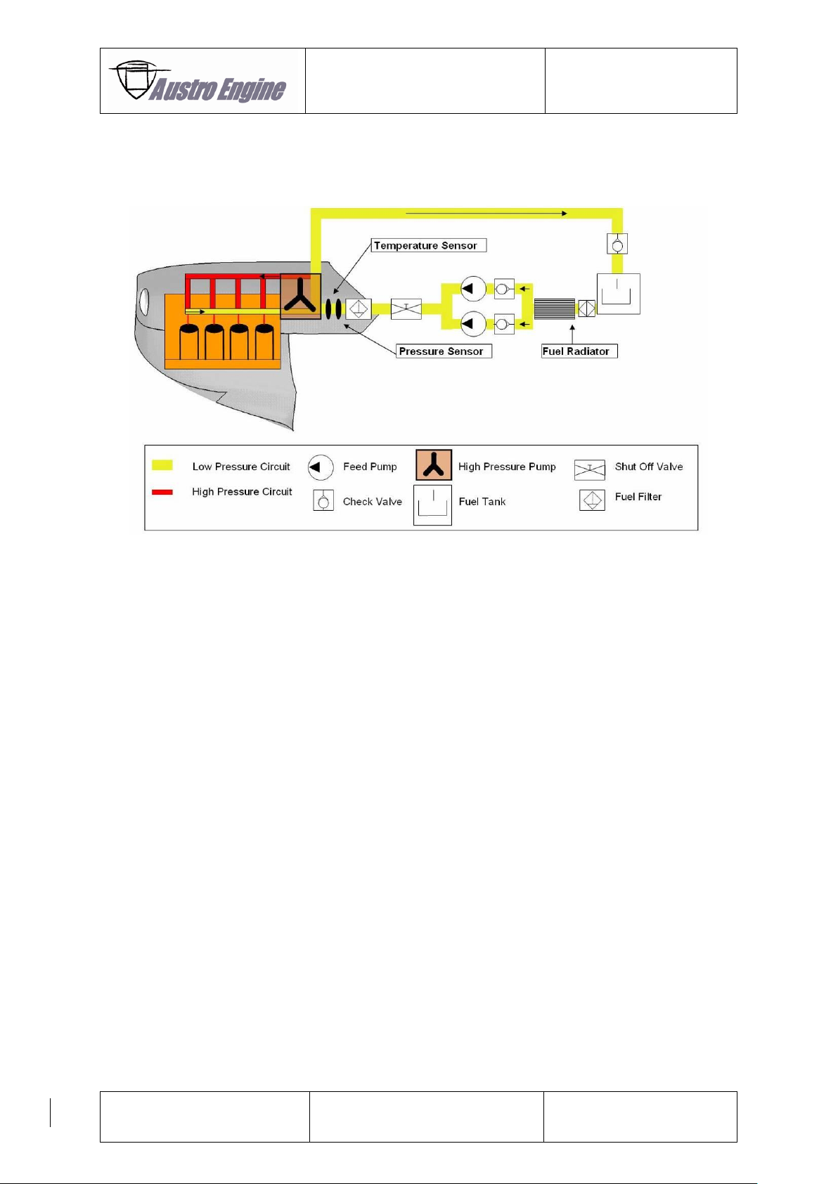
In the following picture a typical Fuel System of the E4P engine is shown.
Fig. 6.1: Fuel System
In the fuel feeding line two feeding pumps are provided which deliver fuel at low pressure to the high
pressure pump. Between feeding pumps and high pressure pump a fuel filter is installed which is able
to cope with the contaminants expected to occur during 100 hours of operation. Direct at the high
pressure pump inlet the fuel temperature and pressure is measured. In case of a pressure loss the
EECU, which actuates both feeding pumps switches automatically to the inactive pump.
The high pressure pump supplies fuel at maximum 1600 bar to the fuel rail and further to the injectors.
At the high pressure pump a fuel metering unit is installed which ensures that only the required quantity
of fuel is compressed. The necessary rail pressure, which is measured directly at the rail, is controlled
by the rail pressure valve.
Excessive fuel of about 4,5 l/min quantity is used to cool and lubricate the high pressure pump. This
excessive fuel is warmed up and flows back through the return line into the fuel tank.
For approved fuel grades refer to chapter 2.5.6.4
Page 37
Operation Manual
E4P
E4.01.02
Issue date: 15.Nov.2016
Page: 6-3
Revision no: 1
6.4 Coolant System
6.4.1 Standard Coolant System
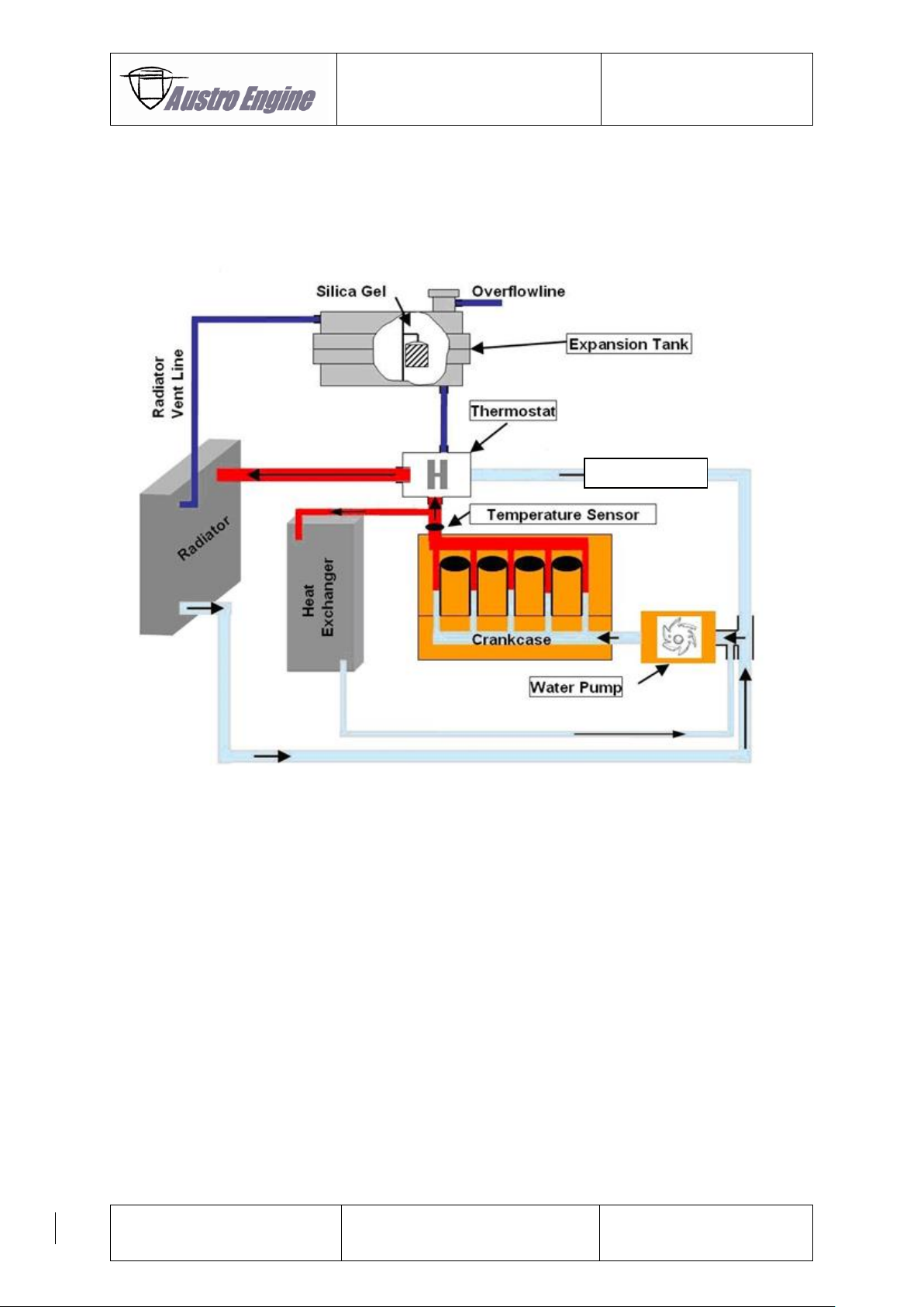
In the following picture the cooling system of the E4P engine is shown.
Fig. 6.2: Cooling system
The water pump pumps the coolant through the engine. The coolant leaves the engine at the heat
exchanger connection point and at the thermostat. If a heat exchanger is installed this circuit is always
flown through.
At the thermostat there are two circuits connected, the small circuit, which is flown through as long as
the engine is cold and the radiator circuit, which starts to be opened as soon as a coolant temperature
measured direct at the thermostat is above 80 °C (176 °F). Above 95 °C (203 °F) coolant temperature
the radiator circuit is full open and the small circuit totally closed.
An expansion tank is provided which contains a silica reservoir to provide the necessary corrosion
protection. The expansion tank has an overpressure valve installed which limits the relative pressure in
the coolant system to max. 2,3 bar. In addition a low pressure valve is installed to protect the coolant
system from negative pressure.
For approved coolant refer to chapter 2.5.7.2
Small Circuit
Page 38
Operation Manual
E4P
E4.01.02
Issue date: 15.Nov.2016
Page: 6-4
Revision no: 1
6.4.2 Coolant System with optional Gearbox Oil Cooler
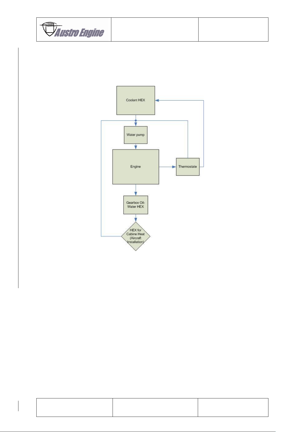
In addition to the standard cooling circuit a Gearbox Oil-Water Heat Exchanger (HEX) is integrated in
the circuit (see Fig. 6.3). The example for an acceptable standard cooling circuit (refer to Fig. 6.2) is
only extended by the gearbox HEX.
Fig. 6.3: Coolant Circuit with optional Gearbox Oil Cooler
The optional available gearbox oil-water HEX, which is directly installed at the rear side of the gearbox,
permits to cool the gearbox oil. An overheating of the gearbox in warm ambient air is minimized with
the link of the gearbox oil to the engine water coolant system via the optional gearbox oil-water HEX.
In correlation to that the gearbox reaches faster its operating temperature.
Page 39

Operation Manual
E4P
E4.01.02
Issue date: 15.Nov.2016
Page: 6-5
Revision no: 1
6.5 Lubricating System
The lubricating system of the engine consists of an internal oil pump, which pumps the engine oil
through the oil filter, the coolant-oil heat exchanger and the lubrication ports of the engine.
In front of the oil filter the oil pressure is measured. The oil temperature is measured in oil sump next
to the oil filler neck. As the coolant temperature is regulated the coolant-oil heat exchanger provides
regulated oil temperatures.
The breather air out of the crankcase is guided through an oil separator. After the oil separator the
crankcase air is released through the breather line into the environment.
In front of the engine a gearbox is provided. This gearbox has its own lubrication circuit. An internal oil
pump pumps the gearbox oil to the lubrication points of the gearbox and to the governor flange. Thus
the propeller pitch adjustment is provided by the gearbox oil.
For approved engine and gearbox oil refer to chapter 2.5.6.1
Page 40
Operation Manual
E4P
E4.01.02
Issue date: 15.Nov.2016
Page: 6-6
Revision no: 1
6.6 Electrical System
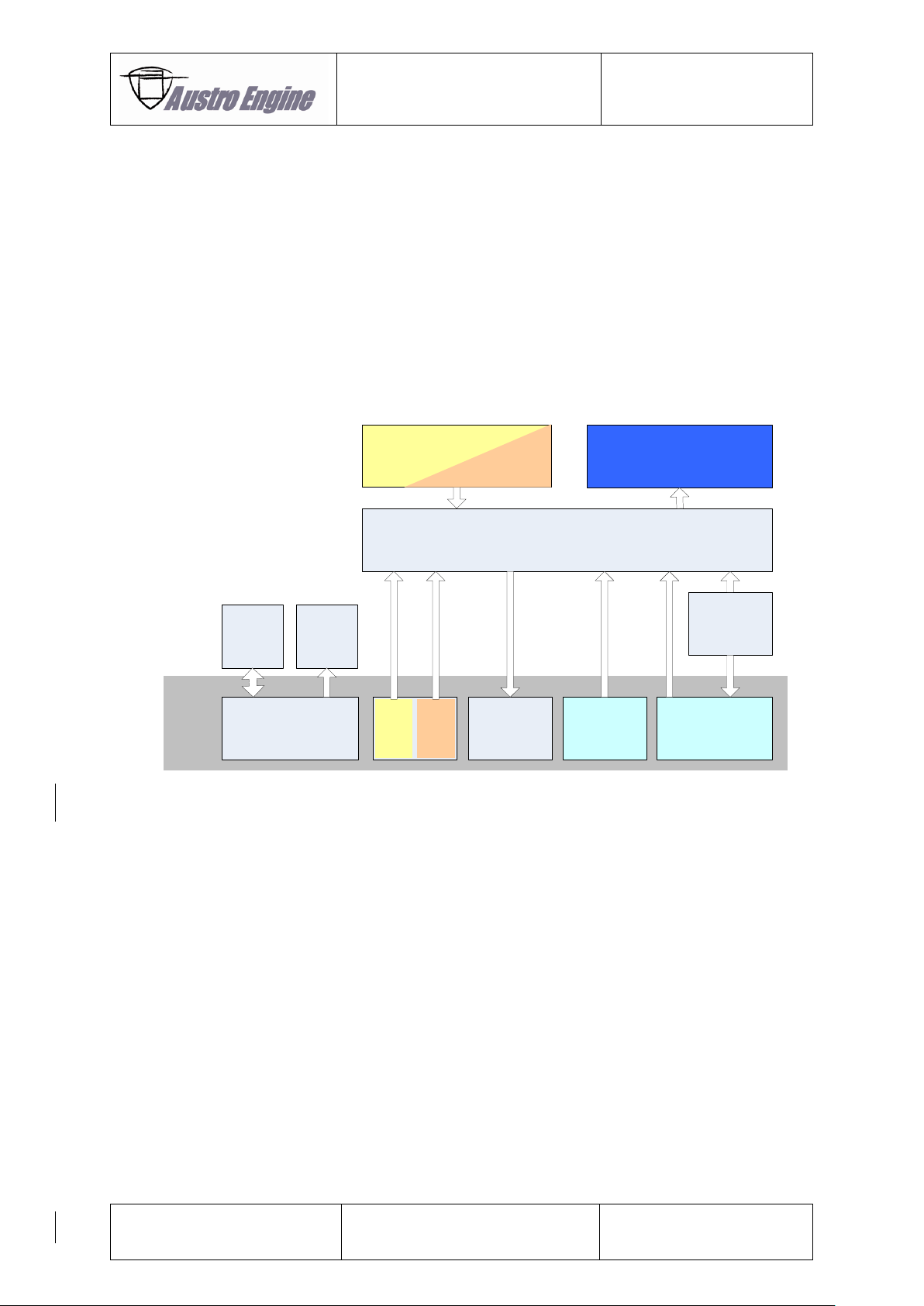
The Electrical System consists of the following major Components:
– Starter
– Generator
– GPC – Glow Plug Control Unit
– EECU – Electronic Engine Control Unit
– Sensors & Actuators
The EECS Block Diagram shows the connection between the EECS components which are used in the
E4P Engine and displays also the Interface from the Airframe to the EECS
of the E4P.
Fig. 6.4: EECS Block Diagram
EECU
Actuators
Glow
Plug
Control
Starter
Generator
A/C
EECS
Engine
Monitoring
System
3way Cockpit
Switch
A/C PowerA/C Interface
Engine Sensors
Power
Lever
Page 41

Operation Manual
E4P
E4.01.02
Issue date: 15.Nov.2016
Page: 6-7
Revision no: 1
The starter is manually controlled by the pilot. The EECU will detect a running engine at 600rpm
(Propeller) and further activation is not necessary.
The Generator is a 28V/70A power supply which consists of an alternator mounted to the engine and
an external regulator. This power supply is used to supply the EECS and the airframe.
The Glow Plug Control Unit is only used to enhance the cold starting behavior of the engine on ground.
It controls the power which is dissipated by glow plugs. These quick start glow plugs help to ignite the
compressed fuel/air mixture because of their hot surface temperature.
The EECU is a 28V supplied device which consists of two similar parts, called ECU A and ECU B. Each
ECU is able to control the engine itself. At each self test both ECU channels will be tested.
Depending on the operating hours count the active ECU will change at each engine start. The other ECU
channel is in hot standby that means active, evaluating sensor values but not operating actuators.
In case of a detected failure on one ECU an internal voter can switch over to the alternate channel.
If different kinds of failures are active at the same time, the switch over decision is based on failure
priorities.
This switch over decision can be overruled by the pilot by manually forcing one channel.
The interface to the engine indications in the A/C is realized via a serial Bus (CAN-Bus).
The pilot interface is realized over Power Lever Sensors. Each ECU has it´s own sensor. Each sensor
has two outputs which are used to perform plausibility checks of the sensor.
Page 42
Operation Manual
E4P
E4.01.02
Issue date: 15.Nov.2016
Page: 6-8
Revision no: 1
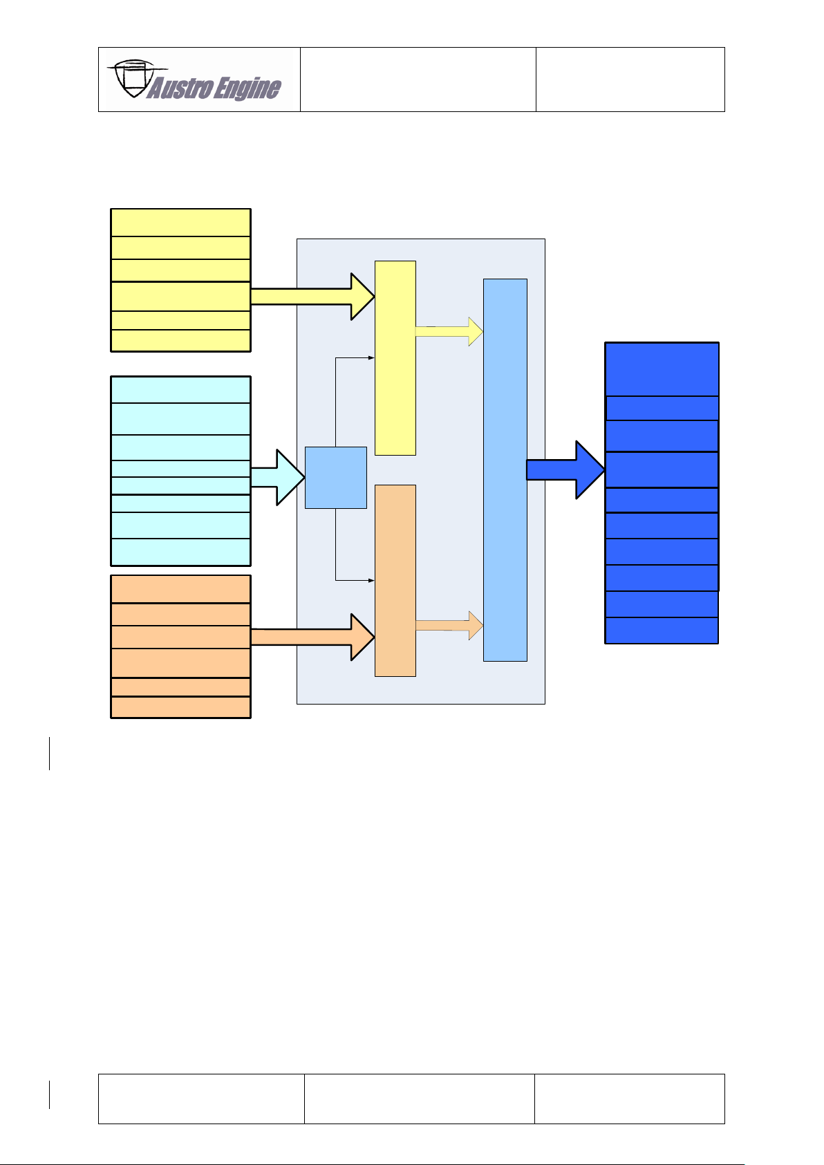
6.6.1 EECU Functions
Sensors and Actuators
Fig. 6.5: Sensors and Actuators
Sensors ECU A
Actuators
Camshaft Sensor
Crankshaft Sensor
Intake Air Temperature
Sensor
Boost Pressure Sensor
Injectors (4)
Governor Actuator
Boost Pressure
Acutator
Rail Pressure
Control Valve
Fuel Metering Unit
Fuel Pump B
Fuel Pump A
ECU A
Relay
Matrix
EECU
ECU B
Power Lever Sensor
Shared Sensor
Signal
Conditioning
Shared Sensors
Gearbox Temperature
Sensor
Oil Temperature Sensor
Fuel Pressure Sensor
Rail Pressure Sensor
Coolant Temperature
Sensor
Fuel Temperature Sensor
Oil Pressure Sensor
Sensors ECU B
Camshaft Sensor
Crankshaft Sensor
Intake Air Temperature
Sensor
Boost Pressure Sensor
Power Lever Sensor
Caution Lamp A
Caution Lamp B
Page 43

Operation Manual
E4P
E4.01.02
Issue date: 15.Nov.2016
Page: 6-9
Revision no: 1
Sensors
● Power Lever Sensor
o Power Lever Sensor position evaluation
o Hall Effect Sensor with dual output
● Crank Shaft Sensor
o Engine speed evaluation
● Cam Shaft Sensor
o Engine position evaluation
● Fuel Pressure Sensor
o Used for evaluation of the fuel pressure after the pre-supply pump
● Oil Pressure Sensor
o Used for evaluation of the engine oil pressure
● Rail Pressure Sensor
o Used to evaluate the rail pressure
● Boost Pressure Sensor
o Boost (Intake Air) Pressure evaluation
● Coolant Temperature Sensor
o Used for coolant temperature evaluation
● Fuel Temperature Sensor
o Used for fuel temperature evaluation
● Gearbox Oil Temperature Sensor
o Used for gearbox temperature evaluation
● Engine Oil Temperature Sensor
o Combinant Sensor used for engine oil temperature evaluation
● Intake Air Temperature Sensor
o Intake Air Temperature evaluation
Actuators
Injectors
Boost Pressure Actuator
Rail Pressure Control Valve
Fuel Metering Unit
Pre-Supply (electrical) Fuel Pump
Governor Set Point Actuator
Caution Lamps
Page 44
Operation Manual
E4P
E4.01.02
Issue date: 15.Nov.2016
Page: 6-10
Revision no: 1
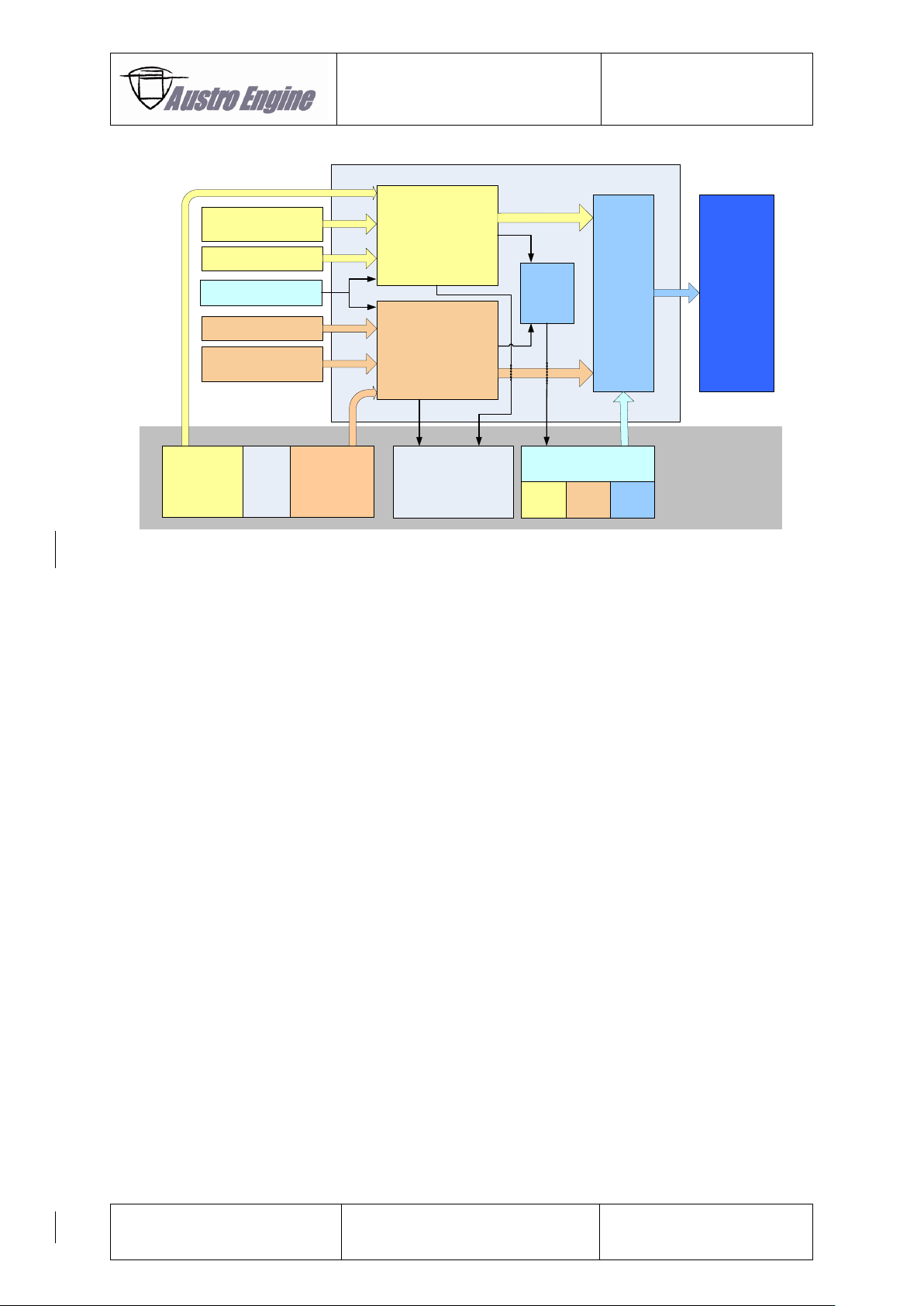
Fig. 6.6: EECU
● Electrical Interfaces
o Outputs protected against
Short Circuit Ubatt
Short Circuit GND
o Diagnosis on Outputs and Sensor Inputs
Short Circuit Ubatt
Short Circuit GND
Open Load
o Sensor Inputs
Linearization of the input voltage
According to the sensor characteristics
● Monitoring of external interfaces
o External interfaces are monitored (sensors, actuators)
o A recognised failure (e.g. electrical) is internally reported
o Reported failures may inhibit other functions/monitoring
● SW Function Montoring
o Separately calculated Values are used for monitoring the main Engine Control Functions
(e.g. Engine Speed Calculation, Injection Quantity Calculation)
● EECU Hardware Monitoring provided
o Internal Supplies
o Internal Memories
o Internal communication
ECU A
Voter
Sensors ECU A
Sensors ECU B
Shared Sensors
Relay
Matrix
Actuators
3way Cockpit
Switch
EECU
ECU A VoterECU B
Power Supply
ECU A
Power Supply
ECU B
ECU B
Engine
Indications /
Annunciations
A/C
Sensor A Sensor B
Power
Lever
Page 45

Operation Manual
E4P
E4.01.02
Issue date: 15.Nov.2016
Page: 6-11
Revision no: 1
● Failure monitoring / Fault Code Memory
o Reported Failures
are stored in the Fault Code Memory
Up to 20 entries
Can lead to an ECU switch over
Can activate the ECU caution
Can cause a substitute function (e.g. substitute value)
● ECU Switch Over
o Reported Failures can lead to an automatic switch over
An internal logic (Voter) selects the ECU to be active
The Pilot can overrule the decision of the EECU
The magnitude of power change can be up to 10%
The typical switch over time is 10 ms.
● Diagnosis via defined CAN- Protocol possible
o AE diagnostic tool (AE 300 wizard)
● Eventrecorder and Datarecorder provided
o Eventrecorder stores defined „Events“ (e.g. reported failures, crossed limits)
o Datarecorder stores cyclically predefined values
Time stamp based on a Real Time Clock
● Statistics
o Records statistics of 8 physical parameters
o Engine and ECU uptimes are recorded
Page 46

Operation Manual
E4P
E4.01.02
Issue date: 15.Nov.2016
Page: 6-12
Revision no: 1
6.6.2 Engine Speed and Power Regulation
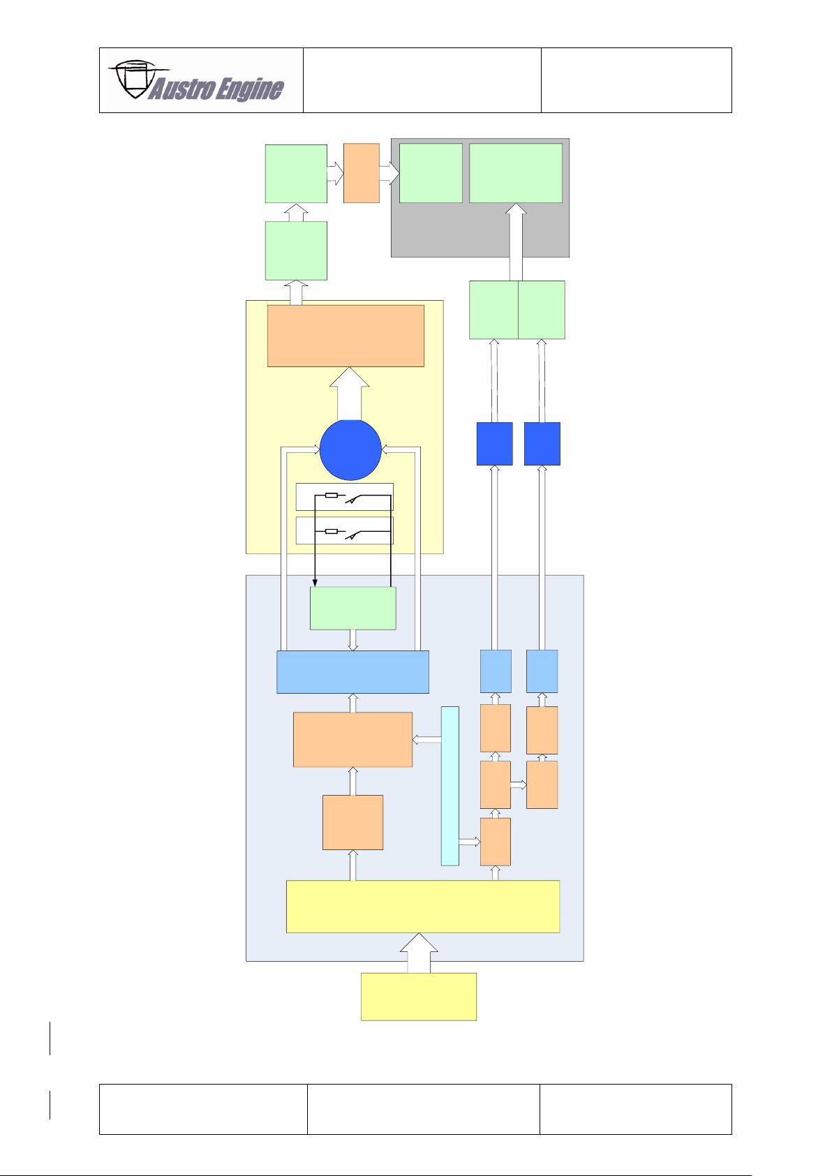
The desired propeller speed set point is calculated depending on the power lever sensor position. The
current engine speed is used to compute the deviation of the actual propeller speed from the set point.
The deviation is converted into an output ratio for the set point actuator. The propeller speed set point
is set by an electric motor (actuator) in the governor system. This electric motor substitutes the
conventionally used Bowden Cable.
The governor itself controls the propeller speed via the propeller blade pitch angle adjustment. The
actuator control ensures together with the monitoring a safe and correct actuation.
If the set point is reached the actuator is deactivated (hysteresis provided).
The requested engine torque is calculated depending on the power lever position and the engine-speed.
– Depending on the requested torque the resulting injection quantity (fuel mass) is calculated.
– Depending on the calculated injection quantity the required boost pressure (air mass) is
calculated.
Page 47
Operation Manual
E4P
E4.01.02
Issue date: 15.Nov.2016
Page: 6-13
Revision no: 1
Fig. 6.7: EECU and Governor
Engine
Governor
Right
Endstop
Left
Endstop
ECU
Set Point
Actuator
(Motor)
Propeller
Speed
R2
Actuator
Control
Propeller
Speed
Control
End Stop
Monitoring
Propeller
Speed
Set Point
Propeller
Pitch
Power
Lever
Sensor
Power
Lever
Sensor
Signal
Evaluation
Injection
Quantity
Calculation
Actuator
Control
Engine
Torque
Injection
Quantity
Engine Speed Information
Actuator
Set Point
Calculation
Demanded
Torque
Calculation
Actuator
Control
Calculation
Desired
Propeller
Speed
R1
Boost
Pressure
Calculation
Actuator
Control
Actuator
Control
Calculation
Boost
Pressure
Boost
Pressure
Actuator
Injectors
Gear
Box
Engine
Speed
Page 48

Operation Manual
E4P
E4.01.02
Issue date: 15.Nov.2016
Page: 6-14
Revision no: 1
6.6.3 Error Handling
In the following tables the engine control system errors and their error handling are listed. Three
different types errors are known:
Errors which lead to a latched caution indication
Errors which lead to a non-latched caution indication
Not indicated errors
In case of a latched caution an unscheduled maintenance is necessary and Austro Engine
GmbH has to be informed.
6.6.3.1 Description of ECU Switch Over
In case of an ECU switch over, the other ECU channel takes over the control of the engine.
This control mode change can lead to slightly different power demand setting (up to 5 %), due to the
tolerances of the sensor mounting to the power lever.
This switch over can lead to a temporarily (less than 1 sec) and slight deviation in the desired speed till
the ECU internal control functions are aligned to the engine operation state.
If a failure occurs which results in reduced engine control capability (e.g. injector failure) the power
performance is also reduced with the now active ECU channel.
If a failure occurs and the now active ECU can rely on plausible values (e.g. Boost Pressure Sensor
defect) the performance of the engine will remain unchanged.
Because both ECU´s are similar, also two warnings are provided to display that one or both channels
detect a failure
Page 49
Operation Manual
E4P
E4.01.02
Issue date: 15.Nov.2016
Page: 6-15
Revision no: 1
6.6.3.2 Resetting ECU caution in Operation
A procedure may be performed for resetting a non-latched caution according to the description in this
section.
If a non-latched caution failure occurs, this may lead to an ECU switch over e.g from ECUA to ECU B.
In the then passive ECU the last valid caution status is stored and not reset, even if the cause of the
caution is not valid any more.
Once the failure disappears and the caution is automatically reset in the active ECU, it is possible to
reset the failure also in the passive ECU.
(e.g. fuel pressure failure caused by flight maneuver, or air-filter icing solved by using alternate air)
Select with the Voter-switch the ECU that reports the failure. Wait for maximum 6 seconds.
If the caution is not reset, go back to AUTO and perform further actions according to the Aircraft
Manuals.
If the caution is reset, go back to AUTO and inform your Maintenance organization at next scheduled
maintenance.
If the operation of the engine on the manually selected ECU (e.g. rough engine run,
fluctuation in engine power or speed) is not as expected, go back to AUTO immediately.
Perform this procedure only if the flight envelope allows to perform this procedure safely.
Take into account a sudden engine shut down when switching manually to passive ECU
and prepare the necessary actions to recover normal operation of the engine and A/C in
case such an engine shut down occurs.
Page 50

Operation Manual
E4P
E4.01.02
Issue date: 15.Nov.2016
Page: 6-16
Revision no: 1
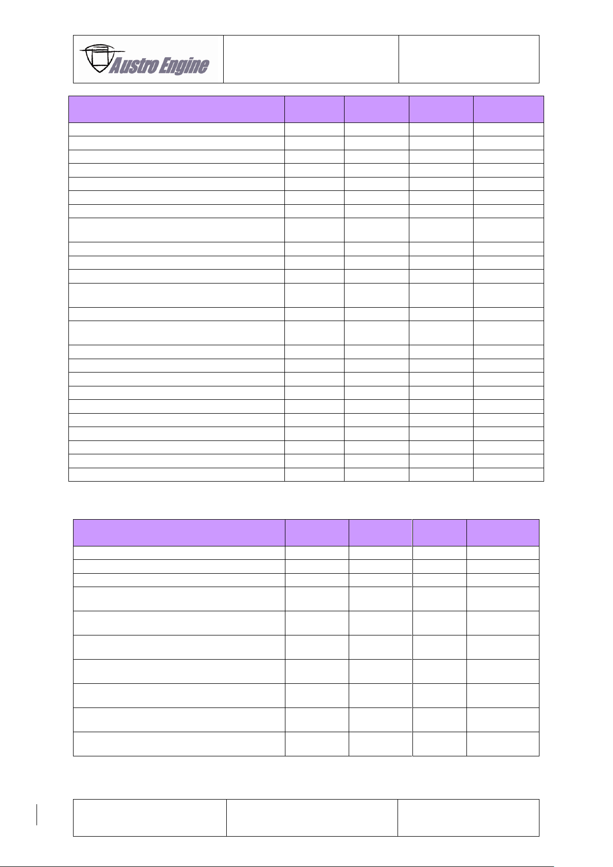
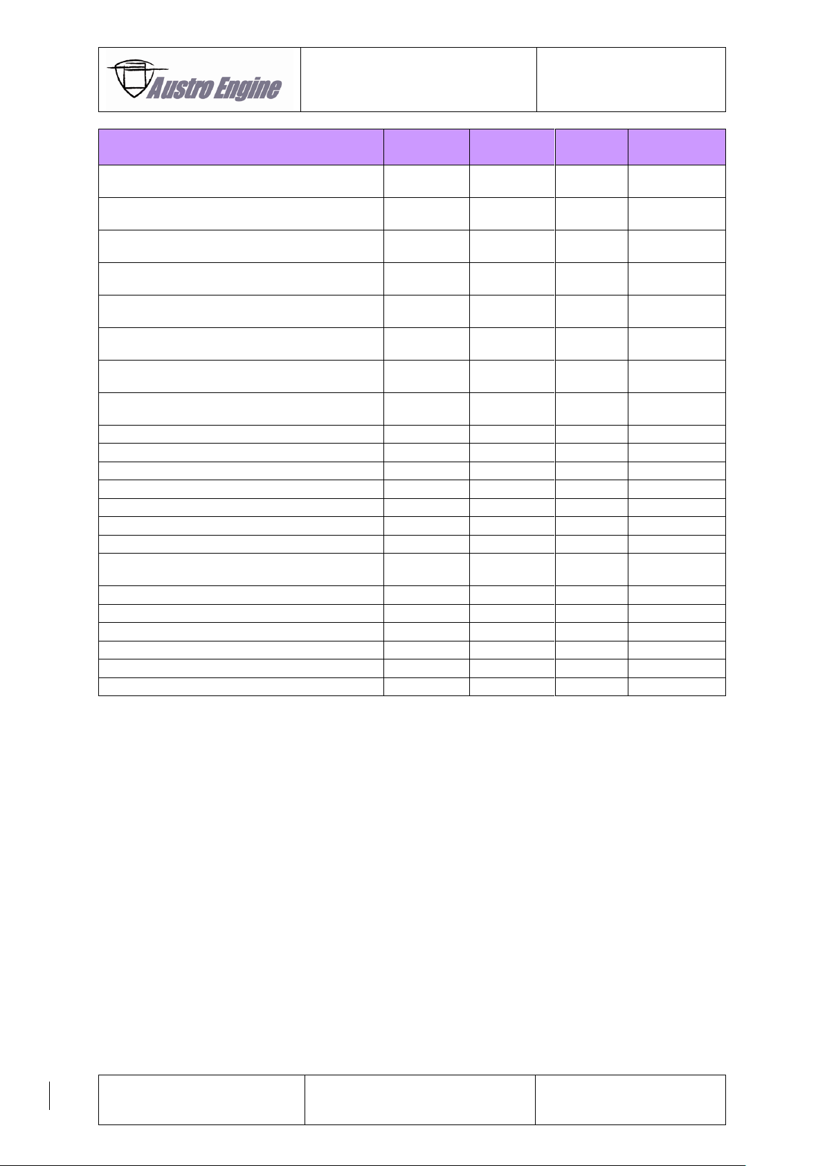
6.6.3.3 Caution Handling Table Software VC33_0_05_18_pre1
The table in this section applies to SW versions VC33_0_05_18_pre1 and later versions.
Latched Caution Indication
Failure description
Failure
Code
Caution
Indication
Caution
Latched
ECU Switch
Over
Analogue-digital converter failure
2319
YES
YES
YES
Power lever sensor 1 failure
1222
YES
YES
YES
Power lever sensor 2 failure
1234
YES
YES
YES
Atmospheric pressure sensor failure
1105
YES
YES
YES
Actuator supply voltage failure
1A04
YES
YES
YES
Battery voltage failure
1615
YES
YES
YES
Boost pressure actuator power stage failure
2526
YES
YES
YES
Boost pressure sensor failure
105
YES
YES
YES
ECU identity failure
1D11
YES
YES
YES
ECU temperature sensor failure
2361
YES
YES
YES
Cam shaft sensor failure
2043
YES
YES
YES
Crank shaft sensor failure
2045
YES
YES
YES
Event: Boost pressure operating range
1E12
YES
YES
YES
Fuel pressure sensor failure
2006
YES
YES
YES
CJ940 power monitoring chip failure
2329
YES
YES
YES
ECU EEPROM failure
1617
YES
YES
YES
ECU hardware encapsulation failure
2386
YES
YES
YES
ECU recovery has occured
2356
YES
YES
YES
ECU recovery has occured
2357
YES
YES
YES
ECU recovery has occured
2358
YES
YES
YES
CJ940 power monitoring over voltage failure
2350
YES
YES
YES
Intake air temperature sensor failure
110
YES
YES
YES
Injection limitation occured
2352
YES
YES
YES
Injection valve Bank 1A failure
2123
YES
YES
YES
Injection valve Bank 1B failure
2139
YES
YES
YES
Injection valve Bank 2A failure
2124
YES
YES
YES
Injection valve Bank 2B failure
2140
YES
YES
YES
Injector driver chip failure A
2324
YES
YES
YES
Injector driver chip failure B
2325
YES
YES
YES
Cylinder 1 - Injection valve failure
201
YES
YES
YES
Injection valve Cylinder 1B failure
2141
YES
YES
YES
Cylinder 2 - Injection valve failure
202
YES
YES
YES
Injection valve Cylinder 2B failure
2142
YES
YES
YES
Cylinder 3 - Injection valve failure
203
YES
YES
YES
Injection valve Cylinder 3B failure
2143
YES
YES
YES
Cylinder 4 - Injection valve failure
204
YES
YES
YES
Injection valve Cylinder 4B failure
2144
YES
YES
YES
MOK-sensor hardware failure
2061
YES
YES
YES
MOK-sensor PWM-signal failure
2062
YES
YES
YES
Metering unit, electric current monitoring
2149
YES
YES
YES
Metering unit, power stage open circuit
2197
YES
YES
YES
Metering unit, power stage short to BATT
2198
YES
YES
YES
Metering unit, power stage short to GND
2199
YES
YES
YES
Page 51
Operation Manual
E4P
E4.01.02
Issue date: 15.Nov.2016
Page: 6-17
Revision no: 1
Failure description
Failure
Code
Caution
Indication
Caution
Latched
ECU Switch
Over
Main relay path 1 failure
1A01
YES
YES
YES
Main relay path 2 failure
1A02
YES
YES
YES
Main relay path 3 failure
1A03
YES
YES
YES
Engine oil pressure sensor failure
1B13
YES
YES
YES
Oil temperature sensor
2014
YES
YES
YES
Injection monitoring failure
2322
YES
YES
YES
Redundant engine speed monitoring failure
2343
YES
YES
YES
Rail pressure control valve, electric current
monitoring
2151
YES
YES
YES
Pressure control valve power stage failure
2500
YES
YES
YES
Pressure control valve power stage failure
2501
YES
YES
YES
Pressure control valve power stage failure
2502
YES
YES
YES
Propeller governor-actuator power stage
failure
1C02
YES
YES
YES
Propeller governor-actuator failure
1C03
YES
YES
YES
Propeller governor-actuator end stop switch
failure
1C04
YES
YES
YES
Electric fuel pump actuator failure
2100
YES
YES
YES
Common rail pressure sensor failure
190
YES
YES
YES
Test of redundant shut off paths
2122
YES
YES
YES
Sensor supply voltage 1 failure
1611
YES
YES
YES
Sensor supply voltage 2 failure
2306
YES
YES
YES
Sensor supply voltage 3 failure
2332
YES
YES
YES
Engine master switch signal failure
1612
YES
YES
YES
TPU monitoring failure
2342
YES
YES
YES
Voter relay failure
1D14
YES
YES
YES
Watchdog connection failure
2323
YES
YES
YES
Non-Latched Caution Indications
Failure description
Failure
Code
Caution
Indication
Caution
Latched
ECU Switch
Over
ECU XA connector failure
1D01
YES
NO
NO
ECU actuator connector failure
1D02
YES
NO
NO
ECU XB connector failure
1D03
YES
NO
NO
Cam shaft and crank shaft synchronisation
failure
2606
YES
NO
NO
Power lever position sensor 1 of ECU A and
B not consistent
1B01
YES
NO
NO
Power lever position sensor 2 of ECU A and
B not consistent
1B02
YES
NO
NO
Barometric air pressure sensing of ECU A
and B not consistent
1B03
YES
NO
NO
Boost pressure sensing of ECU A and B not
consistent
1B04
YES
NO
NO
Cam shaft speed sensing of ECU A and B not
consistent
1B05
YES
NO
NO
Crank shaft speed sensing of ECU A and B
not consistent
1B06
YES
NO
NO
Page 52
Operation Manual
E4P
E4.01.02
Issue date: 15.Nov.2016
Page: 6-18
Revision no: 1
Failure description
Failure
Code
Caution
Indication
Caution
Latched
ECU Switch
Over
Coolant temperature sensing of ECU A and B
not consistent
1B07
YES
NO
NO
Fuel pressure sensing of ECU A and B not
consistent
1B08
YES
NO
NO
Fuel temperature sensing of ECU A and B not
consistent
1B09
YES
NO
NO
Gearbox oil temperature sensing of ECU A
and B not consistent
1B0A
YES
NO
NO
Intake air temperature sensing of ECU A and
B not consistent
1B0B
YES
NO
NO
Engine oil pressure sensing of ECU A and B
not consistent
1B0C
YES
NO
NO
Engine oil temperature sensing of ECU A and
B not consistent
1B0D
YES
NO
NO
Common rail pressure sensing of ECU A and
B not consistent
1B0E
YES
NO
NO
Main relay (ECU) failure
1610
YES
NO
NO
External CAN bus failure
600
YES
NO
NO
Internal CAN receive message failure
1D04
YES
NO
NO
Internal CAN transmit message failure
1D05
YES
NO
NO
External CAN transmit failure
2214
YES
NO
NO
Engine oil pressure failure
1B14
YES
NO
NO
ECU initialization failure
1D12
YES
NO
NO
ECU switchover due to internal CAN
message timeout
1D13
YES
NO
NO
Common rail, metering unit failure 0
2047
YES
NO
YES
Common rail, metering unit failure 1
2015
YES
NO
YES
Common rail, metering unit failure 2
2016
YES
NO
YES
Common rail, metering unit failure 3
2017
YES
NO
YES
Common rail, metering unit failure 4
2018
YES
NO
YES
Common rail, pressure control valve failure 0
2051
YES
NO
YES
Page 53

Operation Manual
E4P
E4.01.02
Issue date: 15.Nov.2016
Page: 6-19
Revision no: 1
Failure description
Failure
Code
Caution
Indication
Caution
Latched
ECU Switch
Over
Common rail, pressure control valve failure 1
2019
YES
NO
YES
Common rail, pressure control valve failure 2
2020
YES
NO
YES
Common rail, pressure control valve failure 3
2021
YES
NO
YES
Common rail, pressure control valve failure 4
2023
YES
NO
YES
Common rail, pressure control valve failure 5
2052
YES
NO
YES
ECU self test timeout failure
1D07
YES
NO
NO
Propeller self test failure
1C01
YES
NO
NO
Event: Fuel pressure operating range
1E13
YES
NO
YES
Boost pressure governor failure
2359
YES
NO
YES
Watchdog communication failure
2321
NO
NO
YES
Not indicated faults
Failure description
Failure
Code
Caution
Indication
Caution
Latched
ECU Switch
Over
Data logger failure
1E02
NO
NO
NO
Caution lamp power stage failure
1C11
NO
NO
NO
Record manager failure
1E01
NO
NO
NO
Real time clock failure
1D06
NO
NO
NO
Indicator: ECU self test is active
1D08
NO
NO
NO
Coolant temperature sensor failure *)
115
NO
NO
NO
Fuel temperature sensor failure *)
180
NO
NO
NO
Gearbox oil temperature sensor failure *)
1B11
NO
NO
NO
Default Values in case of a failure
Failure description
Failure
Code
Default Value
Effect on Engine
Performance
Engine power
display
Power lever sensor 1 failure
1222
Sensor 2 or if both fail 80%
No effect, or if both fail about
80% available ,
Correct
Power lever sensor 2 failure
1234
Sensor 1 or if both fail 80%
No effect, or if both fail about
80%,
Correct
Atmospheric pressure sensor failure
1105
800mbar
Limitation of the engine
Correct
Battery voltage failure
1615
24V
No effect
Correct
Boost pressure sensor failure
105
2600mbar
About 80%of the engine power
shall be available.
Deviates
Coolant temperature sensor failure *)
115
-20°C or 60°C depending on oil
temperature
No effect
Correct
ECU temperature sensor failure
2361
100°C
No effect
Correct
Fuel pressure sensor failure
2006
2,5bar
No effect
Correct
Fuel temperature sensor failure
180
21°C
No effect
Correct
Gearbox oil temperature sensor failure
*)
1B11
0°C (only in baseline 13 40°C)
No effect
Correct
Intake air temperature sensor failure
110
60°C
As stated in the Performance
Diagrams at 60°C Intake Air
Temperature
Deviates
Engine oil pressure sensor failure *)
1B13
0,03bar
No effect
Correct
Oil temperature sensor *)
2014
70°C
No effect
Correct
Common Rail pressure Sensor faiilure
190
Control Set Point
About 80%of the engine power
shall be available
Deviates
*) If the sensor is faulty an error value will by transmitted to the display instrument (e.g. Garmin G1000)
which marks the corresponding value as faulty.
Page 54

Operation Manual
E4P
E4.01.02
Issue date: 15.Nov.2016
Page: 6-20
Revision no: 1
– Intentionally left blank –
Page 55
Operation Manual
E4P
E4.01.02
Issue date: 15.Nov.2016
Page: 7-1
Revision no: 1
7 Additional Information
7.1 Propeller Self Test (Automatic Run-Up Test)
Description:
The propeller governor self test has been designed to emulate the manual run-up test performed by
the pilot of an aircraft equipped with a conventional (mechanical) propeller control lever. With the single
power lever installation of the E4P engine, the self test button must be pressed during the automatic
run up. The self test button in the cockpit has to be released once before a new (subsequent) self test
can be initiated by pressing the button again.
Release Criteria:
The propeller governor self test will only be released if the following release conditions have been met:
● Aircraft on the ground.
● Prop speed = idle (below 1150rpm).
● Power lever = idle (below 5% power lever position).
● No errors pending.
● Self test button active (and pressed during the whole test run).
● Gearbox oil temperature above 35°C
The EECU will increase the prop speed to about 1900 rpm producing thrust. Therefore the
brakes have to be applied during the whole test run to prevent the A/C from moving.
The engine oil temperature and gearbox oil temperature shall be within the green range
of the respective engine indicators before initiating the self test.
Test Abortion:
The propeller governor self test will abort immediately and the prop speed will be reduced to idle for
the following reasons:
● “Self test”-button has been released by the pilot.
● “Weight on wheels”-switch has been released for more than 1 sec.
● Power lever has been moved above the 5% position.
● An error has been detected by the EECU (for failure analysis refer to Maintenance
Manual E4.08.04 – “Diagnosing Self Test Failures”).
Cockpit Indications:
For the proper sequence of cockpit indications and possible caution alerts during the self test, refer to
the approved Aircraft Flight Manual.
Page 56

Operation Manual
E4P
E4.01.02
Issue date: 15.Nov.2016
Page: 7-2
Revision no: 1
Copyright
These technical data and the information contain therein are the property of
Austro Engine GmbH and may not be reproduced either in full or in part or passed on to a
third party without written consent from Austro Engine GmbH.
This text must be included in any full or partial reproduction of this documentation.
Copyright © Austro Engine GmbH
 Loading...