

AUSTRALIAN MONITOR HS250P, HS120P, HS4120P, HS4250P, HS2120P Installation And Operational Manual
...Page 1

INSTALLATION AND OPERATION MANUAL
HSP SERIES
CONSTANT VOLTAGE POWER AMPLIFIERS
WITH USB/RS232 CONTROL
HS120P
HS250P
HS2120P
HS2250P
HS4120P
HS4250P
Page 2
PAGE 2
HSP SERIES INSTALLATION AND OPERATION MANUAL
1. LISEZ ces instructions.
2. Tenez ces instructions.
3. Notez tous les avertissements.
4. Suivez toutes les avertissements.
5. N’utilisez pas ce produit près de l’eau (la piscine, la plage, le lac, etc.).
6. Nettoyez seulement avec une étoffe sèche.
7. Ne bloquez aucuns troux de ventilation. Installez en accord avec les
instructions du manufacturier.
8. N’installez près aucunes sources de chaleur comme radiateurs, registres
de chaleur, fours ou les autres équipements (y compris amplificateurs) qui
produisent la chaleur.
9. Ne défaites pas le but de sécurité de la fiche polarisée ou base-type. Une
fiche polarisée a deux tranchants avec un plus large que l’autre. Une fiche
de base type a deux a deux tranchants et une troisième pointe de base,
le tranchant large ou la troisième pointe est fourni pour votre sécurité. Si
la fiche donnée ne conforme pas votre prise de contact, consultez un
électricien pour remplacement de la prise de contact obsolète.
10. Protegez le cordon de secteur contre être marchée dessus ou pincez en
particulier aux fiches, aux douilles de convenance, et au point où ils
sortent de l’appareil.
11. Seulement utilisez attachements/accessoires spécifiés par le manufacturier.
12. Utilisez seulement avec un chariot, un stand, un trépied, un support ou
une table indiquée par le manufacturier, ou vendue avec l’appareil. Quand
un chariot est utilisé, faites attention en déplaçant la combinaison
d’appareil/chariot pour éviter de se déséquilibrer.
13. Arrachez la fiche du dispositif durant éclair et orage ou quand pas utilisé
pour longues périodes de temps.
14. Référez au personnel qualifié de service pour toutes
réparations. La réparation est donnée quand le système
a été endommagé à n’importe façon, par exemple un fil
ou une fiche endommagé(e) de la source d’alimentation.
Avoir été exposé à pluie ou humidité, n’opère pas
normalement, ou avoir été tombé.
15. L’appareil ne doit pas être exposé aux écoulements ou aux éclaboussures
et aucun objet ne contenant de liquide, tel qu’un vase, ne doit être placé
sur l’objet.
16. Branchez l’appareil à une source appropriée et faire que la prise à
débrancher soit facilement accessible.
17. La prise du secteur ne doit pas être obstruée ou doit être facilement
accessible pendant son utilisation. Pour être complètement déconnecté
de l’alimentation d’entrée, la prise doit être débranchée du secteur.
18. AVERTISSEMENT: Pour éviter le risque d’incendie ou de chocs électriques,
ne pas exposer cet appareil à la pluie ou à l’humidité.
19. Un appareil avec la borne de terre de protection doit être connecté au
secteur avec la connexiion de terre de protection.
20. Assurez-vous que l’appareil est hors tension avant de connecter les hauts
parleurs. Verifiez que la sortie des enceintes soit protégées contre un
contact physique. Respecter les polarités des terminaux ainsi que le
câblage des enceintes pendant le fonctionnement afin d’assurer une
utilisation sécurisee.
IMPORTANT SAFETY INFORMATION PRÉCAUTIONS DURANT UTILISATION
1. Read these instructions.
2. Keep these instructions.
3. Heed all warnings.
4. Follow all instructions.
5. Do not use this apparatus near water.
6. Clean only with dry cloth.
7. Do not block any ventilation openings. Install in accordance with the
manufacturer’s instructions.
8. Do not install near any heat sources such as radiators, heat registers,
stoves, or other apparatus (including amplifiers) that produce heat.
9. Do not defeat the safety purpose of the polarized or grounding-type
plug. A polarized plug has two blades with one wider than the other. A
grounding type plug has two blades and a third grounding prong. The wide
blade or the third prong are provided for your safety. If the provided plug
does not fit into your outlet, consult an electrician for replacement of the
obsolete outlet.
10. Protect the power cord from being walked on or pinched particularly
at plugs, convenience receptacles, and the point where they exit from
the apparatus.
11. Only use attachments/accessories specified by the manufacturer.
12. Use only with the cart, stand, tripod, bracket, or table specified by the
manufacturer, or sold with the apparatus. When a cart is used, use caution
when moving the cart/apparatus combination to avoid injury from tip-over.
13. Unplug this apparatus during lightning storms or when unused for long
periods of time.
14. Refer all servicing to qualified service personnel.
Servicing is required when the apparatus has been
damaged in any way, such as power-supply cord or plug
is damaged, liquid has been spilled or objects have fallen
into the apparatus, the apparatus has been exposed to
rain or moisture, does not operate normally, or has been dropped.
15. This appliance shall not be exposed to dripping or splashing water and
that no object filled with liquid such as vases shall be placed on the
apparatus.
16. Plug this apparatus to the proper wall outlet and make the plug to be
disconnected readily operable.
17. Mains plug is used as disconnected device and it should remain readily
operable during intended use. In order to disconnect the apparatus from
the mains completely, the mains plug should be disconnected from the
mains socket outlet completely.
18. WARNING: To reduce the risk of fire or electric shock, do not expose this
apparatus to rain or moisture.
19. An appliance with a protective earth terminal should be connected to a
mains outlet with a protective earth connection.
20. The apparatus should be disconnected from the mains completely before
speaker wiring. The speaker output should be proper protected from direct
contact and pay attention to speaker connections, terminals and speaker
wiring during normal operation.
Page 3
PAGE 3
HSP SERIES INSTALLATION AND OPERATION MANUAL
Revision 1.1: Jul 2018
Introduction 3
Features & Protection Features 4
Controls, Connectors and Indicators 5
Software Setup 8
Installation 13
Basic Setup and Operation 16
Maintenance 17
Specifications 18
Serial Command Protocol 22
WARNING!
TO PREVENT FIRE OR SHOCK HAZARD, DO NOT USE THE PLUG WITH
AN EXTENSION CORD, RECEPTACLE OR OTHER OUTLET UNLESS THE BLADES
CAN BE FULLY INSERTED TO PREVENT BLADE EXPOSURE.
TO REDUCE THE RISK OF FIRE OR ELECTRIC SHOCK, DO NOT EXPOSE
THIS APPLIANCE TO RAIN OR MOISTURE.
TO PREVENT ELECTRICAL SHOCK, MATCH WIDE BLADE PLUG TO WIDE SLOT & FULLY INSERT.
CAUTION
THESE SERVICING INSTRUCTIONS ARE FOR USE BY QUALIFIED SERVICE PERSONNEL ONLY.
TO REDUCE THE RISK OF ELECTRIC SHOCK DO NOT PERFORM ANY SERVICING OTHER THAN THAT
CONTAINED IN THE OPERATING INSTRUCTIONS UNLESS YOU ARE QUALIFIED TO DO SO.
CAUTION
RISK OF ELECTRIC SHOCK
DO NOT OPEN
The lightning flash with
arrowhead symbol, within an
equilateral triangle, is intended to
alert the user to the presence of
uninsulated “dangerous voltage”
within the product’s enclosure
that may be of sufficient
magnitude to constitute a risk
of electric shock to persons.
WARNING:
TO REDUCE THE RISK OF
ELECTRIC SHOCK, DO NOT
REMOVE COVER (OR BACK).NO
USER SERVICEABLE PARTS
INSIDE. REFER SERVICING TO
QUALIFIED SERVICE
PERSONNEL.
The exclamation point within an
equilateral triangle is intended
to alert the user to the
presence of important operating
and maintenance (servicing)
instructions in the literature
accompanying the appliance.
For European Union countries: This symbol on
the product or its packaging indicates that this
product must not be disposed of with other waste.
Instead, it is your responsibility to dispose of your
waste equipment by handing it over to a designated
collection point for the recycling of waste electrical
and electronic equipment.
Please contact your local authority for further details
of your nearest designated collection point.
Rating plate and caution marking are marked on the back enclosure of the apparatus
INTRODUCTION AND CONTENTS
Congratulations on choosing Australian Monitor for your professional
amplification requirements.
The design of our HSP series constant voltage power amplifiers
embraces all the aspects of a well-designed amplifier. The visual
design, mechanical, electrical and sonic parameters, along with our
dedicated manufacturing process, have all been optimised to provide a
professional tool that exhibits quality, reliability and longevity.
The HSP series amplifiers are 1 unit 1.75” high, 19” wide, or 2 unit
3.5” high, 19” wide rack mountable units depending on the model.
Models are available in 1, 2 and 4 channel versions. The HSP amplifier
is fully controllable over the included USB and RS232 interface which
provides configuration and monitoring capabilities. An included mini
DSP also allows control of the volume, muting, compressor/limiter and
input channel selection which feeds an efficient Class D amplifier to
deliver 120W or 250W of output power per channel.
These amplifiers have been specifically designed to deliver their high
power output with minimal distortion, and provide the critical degree
of control required by your speakers.
HSP SERIES
Page 4
PAGE 4
HSP SERIES INSTALLATION AND OPERATION MANUAL
FEATURES & PROTECTION FEATURES
FEATURES
•
Single Channel - HS120P- 1 x 120W, HS250P – 1 x 250W
•
Dual Channel - HS2120P – 2 x120W, HS2250P - 2x250W
•
Quad Channel - HS4120P – 4 x 120W, HS4250P – 4 x 250W
•
Efficient Class-D amplification
•
4Ω/70V/100V output operation
•
1, 2 or 4 input to output channel variants with balanced input channels
•
DSP provides:
>
Volume Control
>
High/Low Pass Filtering
>
Compressor/Limiter
>
Input/Output channel selection matrix
>
Channel inversion
>
Status monitoring
•
PC controlled software graphical user interface control
•
USB and RS232 interface for DSP configuration and overall product control
•
Dedicated external Mute, Standby and Fault monitoring connector
•
Amplifier and Signal status LED indicators
•
Power factor corrected universal switch mode power supply (excluding
HS120P)
•
1RU (1 and 2 channel models) / 2RU (4 channel models) height with front rack
mount ears
•
Fan cooled
PROTECTION FEATURES
•
Clip protection
•
Short-circuit protection
•
Overload protection
•
Thermal protection
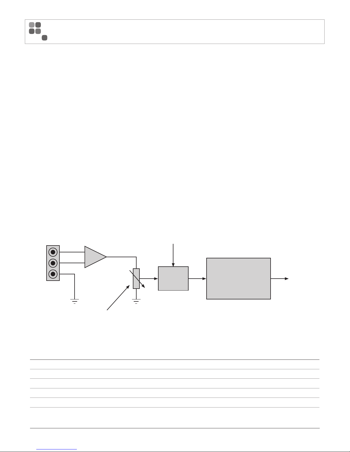
HSP Amplifier Block Diagram
10 Vrms Max
Phoenix Balanced Input
To Speaker
Terminals
-128 dB ~ +12 dB GAIN
-128 dB ~ 0 dB ATTENUATION
DSP
Class D
Power Amplifier
GLOSSARY
Ter m Meaning
DSP Digital Signal Processor
USB Universal Serial Bus
XLR Audio electrical connector type
LED Light Emitting Diode.
Phoenix connector Terminal block connector type. Also known as a Euroblock.
DIP switch Dual in-line package switch. Used on the front and rear of the product to select various settings
Page 5

PAGE 5
HSP SERIES INSTALLATION AND OPERATION MANUAL
CONTROLS, CONNECTORS & INDICATORS
FRONT PANEL
HSP 1 Channel 1RU shown in above example.
1
USB Communications Port
Plug in the supplied USB Type A to Mini Type B connector into this port to communicate with the amplifier from the PC software application. The PC software application,
downloadable from the Australian Monitor website, allows for real time monitoring of the amplifier inputs and outputs. The PC software application is also used to
configure the DSP functionality to cater for the installation environment.
Consult the Software Control Over USB setup section of this manual for further details of this control.
2
LED Indicators
Status Indicator
This blue LED indicates various states of the amplifier.
LED MEANING INDICATION
Blue On Normal Operation LED solid on. Indicates that device is powered and that no faults exist.
Blue Slow Flash Standby Mode Flash LED: On for 50ms, Off for 4s
Blue Flash Error Mode LED Off for 2s followed by a flash count of the error code, On for 300ms, Off for 300ms. Multiple errors will be indicated in
consecutive error sequences. Refer to the Fault Finding section of this manual to fix any errors displayed.
See the Fault Finding section of this manual to fix any errors displayed.
Protect Indicator
The following table indicates the meaning of each protection mode:
LED Meaning
Yellow flashing Amplifier temperature warm
Yellow on Amplifier temperature hot
Red flashing Amplifier over temperature*
Red on Amplifier protect
See the Fault Finding section of this manual to fix any errors displayed.
* In the advent of a thermal overload, the internal operating temperature
of the amplifier has exceeded a safe level of operation. The fan will
continue to run and once the amplifier has cooled it will return to
normal operation.
Signal LED
The following table indicates the meaning of the signal LED
LED Meaning
Green flashing Audio signal mute
Green on Audio signal present
Output Clip indicator
A red LED will illuminate when output signal clipping occurs.
3
Power Switch
Press the switch to the up position to power the unit on. At start-up (turn-on),
the input to the amplifier is muted for approximately two seconds.
1 2 3
Front panel
Page 6

PAGE 6
HSP SERIES INSTALLATION AND OPERATION MANUAL
REAR PANEL
1
Mains Input Connector
Your amplifier is fitted with a standard IEC 60320-C14 socket for mains
connection. Use the mains cable supplied to power up the unit.
NOTE: Your unit must always be earthed!
2
Speaker Outputs
The class D amplifier output features 100V Line, 70V Line or 4 Ohm low
impedance operation.
IMPORTANT: Remove the speaker connector link if operating the amplifier
in 4 Ohm operation.
NOTE: Only one output type should be used at a time.
3
RS232 Communications Port
The RS232 port is designed to be connected to an external control system or to
a remote PC. Using an RS232 converter (not supplied), connect to this port to
communicate with the amplifier from the PC software application or via serial
commands. The PC software application allows for real time monitoring and
configuration of the amplifier.
Consult the Software Control Over RS232 setup section of this manual for
further details of this control.
4
External Mute, Standby and Fault
External Mute
Connect this input to ground (GND) to mute amplifier channels.
Consult the External Mute section of this manual for further detail of this
control.
Standby
Connect this input to ground (GND) to enable standby mode.
Consult the Standby Input section of this manual for further detail of this
control.
Fault
This active low output indicates a fault in the amplifier. There are two possible
faults that can be indicated:
•
The amplifier has gone into thermal shutdown due to a measured high
temperature
•
The amplifier has detected an overload condition on the speaker terminals
Consult the Fault section of this manual for further detail of this control.
5
Input Channel Clip LEDs
The input channel clip LEDs are used to indicate that the input signal is being
clipped. If the input is clipping, reduce the signal by turning the attenuation pot
counter-clockwise (when viewed from rear) until the clip LED ever so slightly
turns on with an input source present.
The input source should be representative of the audio that will be used in the
system on a daily basis.
CONTROLS, CONNECTORS & INDICATORS
1
1 6
3 4 6 7 8
3 72
2 25 2 2
4 85
HSP 1 Channel 1RU rear panel shown above
HSP 4 Channel 2RU rear panel shown above
Page 7
PAGE 7
HSP SERIES INSTALLATION AND OPERATION MANUAL
HSP Amplifier
HSP Amplifier
CONTROLS, CONNECTORS & INDICATORS
6
Input Signal Attenuation Pot
The fully clockwise position (when viewed from rear) of the input signal
attenuation pot provides no attenuation (ie 0 dB). Turning the pot counter
clockwise provides a logarithmic attenuation all the way to -128 dB.
7
Phoenix Balanced Input
A balanced male 3-pin (3.81mm) Phoenix type connector is provided
on each input channel.
Consult the Balanced Input Wiring section of this manual for further
detail of this control.
8
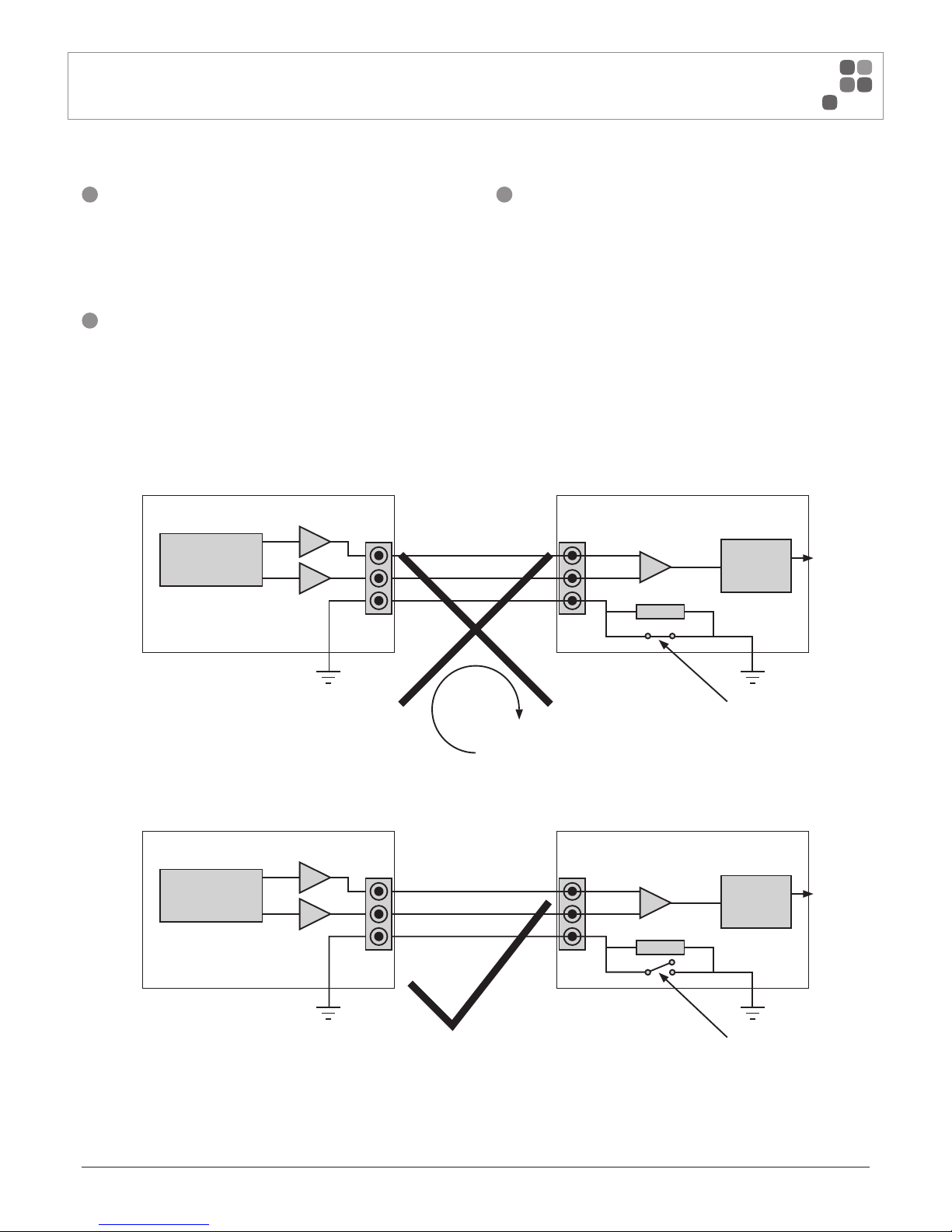
Ground Lift
Use the DIP switches to control the grounding of the audio inputs. The switch for the given channel is pushed down to connect the input signal ground with the mains
safety ground. The piano DIP switch is in the lift position (ie up) when the input ground needs to lifted from the mains safety ground to prevent circulating earth loops.
If at anytime a hum or unwanted noise is experienced then the input should be configured so that the input signal ground is lifted from the mains safety earth. This
minimises the circulating ground loop current by adding in an impedance which results in significantly less loop voltage drop being amplified by the amplifier.
Refer to diagram below which illustrates the above concept:
Audio Source
Mains Safety Earth Mains Safety Earth
Ground Lift Switch in Ground Position
Signal In (‘+’ Hot)
Signal In (‘–’ Cold)
Signal Gnd
Preamp
15 ohms
Circulating
Earth Loops
Amp
Audio Source
Mains Safety Earth Mains Safety Earth
Ground Lift Switch in Lift Position
Signal In (‘+’ Hot)
Signal In (‘–’ Cold)
Signal Gnd
Preamp
15 ohms
Amp
Page 8
PAGE 8
HSP SERIES INSTALLATION AND OPERATION MANUAL
SOFTWARE SETUP
Supported Operating Systems
•
Windows 10
•
Windows 8
•
Windows 7 (32/64 bit)
•
Windows XP (32/64 bit)
Software Download Procedure
1
Navigate to: http://www.australianmonitor.com.au/resources/
Type the product name into the search box as follows (for example):
HS120P
2
Select the latest version of the HSP Control Software Installer VX.X.0
3
Navigate to your downloads folder and double click on the installer to run
4
Plug in a USB/RS232 cable to the HSP power amplifier and turn the
amplifier on
5
Launch the HSP Control Software and connect to the amplifier
Software Control Over USB
1
Turn on the power to the HSP unit by pushing the front panel switch up.
2
Plug in the supplied USB cable to the HSP front panel and PC.
3
Open the software application HSP Control Software VX.X.X.
4
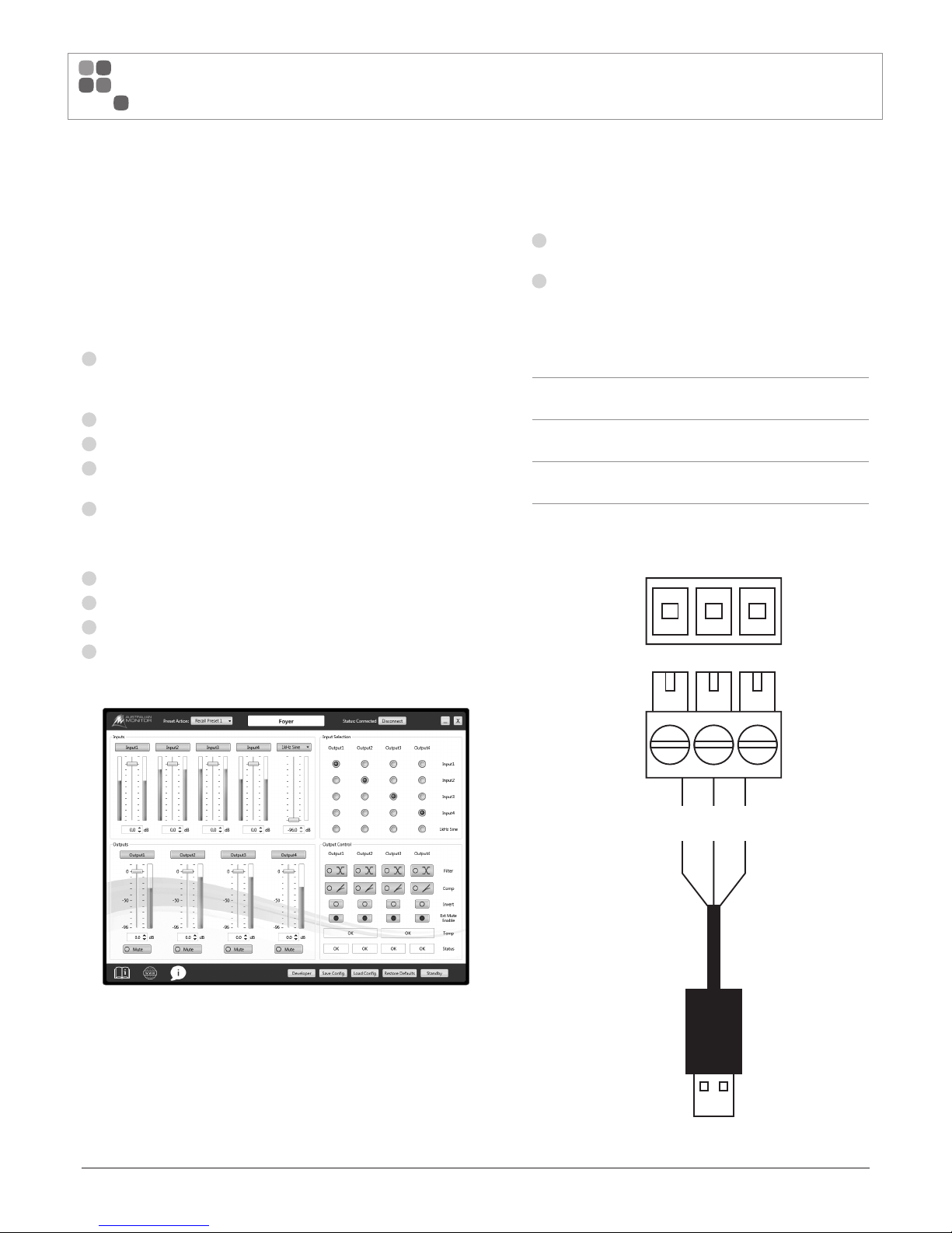
Upon successful connection the main application window will look like
the image below. (Note: The number of channels displayed will depend
on the HSP model):
Software Control Over RS232
The RS232 control port works in two ways
1
As an alternative control port to the front panel USB for longer
distance control using the PC application.
2
To interface to an external control system using serial commands.
i.e. Not using the PC application but directly controlling the unit and
sending discrete commands.
RS232 Connection Setup
TXD
Transmit OUT of amplifier.
Connect to RECEIVE of remote control system
RXD
Receive IN to amplifier.
Connect to TRANSMIT of remote control system
COM Port
Settings
Baud 115200, Data 8, Stop 1, Parity None, Flow None
TXD
RXD
RXD TXD
GND
GND
USB
Page 9

PAGE 9
HSP SERIES INSTALLATION AND OPERATION MANUAL
SOFTWARE SETUP (CONT)
RS232 using the PC application
1
Most modern PC’s require a USB to RS232 converter for RS232 operation.
A suggested RS232 to USB converter is the FTDI (USB-RS232-WE-1800BT_5.0) which can be sourced through most online electronic component
stores.
2
Wire up the USB to RS232 converter like the image at left [see page 8]
using the supplied green 3-way Phoenix connector. Note it’s important that
the RXD and TXD of the HSP pins must join to the TXD and RXD of the
converter respectively.
3
Turn on the power to the HSP unit by pushing the front panel switch up.
4
Plug in the supplied RS232 cable to the rear of the HSP unit and USB port
to the PC.
5
Make sure the driver for the RS232 to USB converter cable has installed
correctly. This can be checked by opening windows device manager. To do
this select (Start -> System -> Device Manager) and then make sure there
are no devices marked as inactive due to a missing driver.
6
Double click on the installed application HSP Control Software VX.X.X.
7
Select the USB to RS232 converter manufacturer from the dropdown
menu. Note: if using the FTDI cable that is suggested above it will display
as (USB Serial Port (COMXX)) where COMXX will display the COM port
number chosen by the PC. See image below:
8
Upon successful connection the main application window will look like the
image below (Note: The number of channels displayed will depend on the
HSP model):
RS232 using an external control system
1
Connect the external control system to the RS232 port of the amplifier.
2
Configure the RS232 port settings as per the setup information above
3
Referring to the serial command section, send and receive commands
using the external control system.
Example command to enter standby:
set device mode standby true
Page 10

PAGE 10
HSP SERIES INSTALLATION AND OPERATION MANUAL
SOFTWARE SETUP (CONT)
Software Developer Mode
A highly recommended method to easily understand the commands being
sent and received by the amplifier is to turn on “Developer” mode on the
PC application. This will open a second window that displays the commands
being sent and received when the user interacts with the PC application.
These commands can then be copied to an external control application
without requiring a detailed understanding of the communication protocol.
NOTE: The “Developer” window is NOT supported in offline mode.
You must be connected to an amplifier
Select the “Developer” mode button shown below
Interact with the application to see commands
being printed to the “Developer” window
Page 11

PAGE 11
HSP SERIES INSTALLATION AND OPERATION MANUAL
SOFTWARE SETUP (CONT)
External Mute
The external mute functionality is activated using the supplied 4-way Phoenix connector. Simply connect the MUTE to GND to mute channels of the amplifier.
See connection diagram listed below for a simple connection:
FAULT
GND
STANDBY
MUTE
The PC application includes toggle buttons to select which amplifier channels are muted using the external mute trigger. Select or deselect the channels required in the
application.
Ext Mute
Enable
*4 channel product shown
Standby
The amplifier has three ways to enter or exit standby in the following priority: Priority 1 – External Input
Priority 2 – Command Interface
Priority 3 – Auto standby
•
If priority 1 is released when the Command interface is enabled you will NOT exit standby. You must explicitly send a standby exit command.
•
If Priority 1 and/or 2 is enabled and then consequently disabled the unit will always exit standby irrespective of priority 3 settings.
However, if priority 3 is enabled it will then re-enter standby after the preset time has elapsed.
Password Protection
To enable password protection on the amplifier, press on the Admin button on the main window, then click Enable to turn on the password protection functionality.
The default username and password are: Username – admin
Password – admin
Page 12

PAGE 12
HSP SERIES INSTALLATION AND OPERATION MANUAL
SOFTWARE SETUP (CONT)
Fault
The FAULT output will be set low (0V) under the following conditions:
•
The amplifier has gone into thermal shutdown due to a measured high temperature
•
The amplifier has detected an overload condition on the speaker terminals
The FAULT output is located on the rear of the HSP unit. Connect the FAULT and GND connection to any external control solution to read this signal.
The FAULT output is an open collector output with a 390R current limiting resistor in series.
Maximum voltage relative to GND 35V
Maximum current 100mA
Priority 1 – External Input
The standby function is activated using the supplied 4-way Phoenix connector.
Simply connect the STANDBY to GND to put the amplifier into standby mode.
See connection diagram listed below:
FAULT
GND
STANDBY
MUTE
Priority 2 – Command Interface
Send the following command using RS232
To enter standby: set device mode standby true
To exit standby: set device mode standby false
You can also enable/disable the software standby using the PC application.
Open the standby dialog box by selecting the “Standby” button and then select
the Standby button under the priority 2 section.
Priority 3 – Auto standby
The amplifier can enter and exit standby based on the presence of audio
on any input. (Note: All input channels are summed together for detection)
Open the standby dialog box in the PC application by selecting the “Standby”
button and set the time and audio threshold under the priority 3 section.
FAULT
390R
GND
Page 13

PAGE 13
HSP SERIES INSTALLATION AND OPERATION MANUAL
INSTALLATION
Power Requirements
Power consumption for your model of the HSP series amplifier is indicated
on the rear panel for 1/8th output power.
Ensure that your mains voltage is the same as the rear panel mains voltage
marker (+/- 10%).
Mounting
The HSP series amplifiers are one or two rack units high (1U) (2U) and will fit
a standard EIA 19” or rack.
Typically amplifiers may be stacked directly on top of each other with no
need for spacing between units, unless installed in high ambient temperature
environments where a single rack unit space between amplifiers will assist
cooling further.
Cooling
The HS120P is convection cooled and does not require any special
consideration.
The HS250P, HS2120P, HS2250P, HS4120P and HS4250P amplifiers are
cooled by axial fans which draw air inside the amplifier and expel the heated air
outside the amplifier. These amplifiers offer variable speed fans which run at
half speed up to full speed when the internal heatsink temperature increases.
An unrestricted airflow into and out from the amplifier must be provided. Any
restriction of the air flow will cause heat to build up within the unit and possibly
force the unit into its thermal shutdown mode.
If the amplifiers are to be operated in an environment where the airflow is
restricted such as sealed racks, cooling should be supplemented by extra
cooling fans to evacuate the heated air and aid the flow of cool air through
the unit.
Balanced Input Wiring
1 2 3
INPUT 1
IMPORTANT: Do not directly connect pin 3 on the amplifier’s input to the
amplifier’s chassis, speaker ground or power ground!
WARNING: Input signal ground should NOT be used as a safety
ground (earth).
The balanced input to the amplifier is 3-pin configuration and requires all
three pins to be connected. Only high quality twin-core shielded cable should
be used.
Pin 1 is the left most pin when viewed from the back of product.
Pin 1 = Hot (non-inverting or in phase)
Pin 2 = Cold (inverting or reverse phase)
Pin 3 = Signal Ground
When wiring from an unbalanced source you must ensure that pin 2 is
connected to pin 3 (Signal Ground), either by linking the pins in the input
connector or by the source equipment’s output wiring.
When wiring for an unbalanced source:
Pin 1 = Hot (non-inverting or in phase)
Pin 2 = Signal Ground
Pin 3 = Signal Ground
Output Wiring
When wiring to your speakers always use the largest gauge wire your
connector will accept. The longer the speaker lead the greater the losses
which will result in reduced power and less damping at the load. We
recommend using a heavy duty, two core flex (four core flex if bi-amping)
10 to 12 gauge (2mm2 to 2.5mm2 or 50/0.25 or equivalent) as a minimum.
Page 14

PAGE 14
HSP SERIES INSTALLATION AND OPERATION MANUAL
INSTALLATION (CONT)
Speaker Outputs
The amplifier output has a 6 pin output screw terminal with a pre-fitted link between the 4Ohm and the high impedance output.
70V
•
Fit the link between 4Ω and the OT-IN. (This connects the amplifier output to the input of the 70/100V transformer)
•
Connect your speaker to the HIGH IMPEDANCE OUTPUT ‘C’ and ‘70V’ connections
100V
•
Fit the link between 4Ω and the OT-IN. (This connects the amplifier output to the input of the 70/100V transformer)
•
Connect your speaker to the HIGH IMPEDANCE OUTPUT ‘C’ and ‘100V’ connections
4Ω or 8Ω operation
•
Remove the link between 4Ω and the OT-IN
•
Connect your speaker to the LOW IMPEDANCE OUTPUT ‘C’ and ‘4Ω’ connections
4/8 Ohm 70V 100V
OUTPUT CONFIGURATION FOR ALL CHANNELS
LOW IMPEDANCE
OUTPUT
Connect the Link for
70V/100V Output Operation
HIGH IMPEDANCE
OUTPUT
LINK
70V
LINK
100V
Page 15

PAGE 15
HSP SERIES INSTALLATION AND OPERATION MANUAL
INSTALLATION (CONT)
Hum Problems
Most equipment is designed for minimum hum when used under ideal
conditions. When connected to other equipment, and to a safety earth in an
electrically noisy environment, problems may occur.
The three ”E”s of hum and hum related noise which can plague your audio
system are:
a) Earth loops
b) Electromagnetic radiation
c) Electrostatic radiation
Earth loops can arise from the interfacing of the various pieces of equipment
and their connections to various safety earths.
This is by far the most common cause of hum, and it occurs when source
equipment and the amplifier are plugged into different points along the safety
earth where the safety earth wiring has a current flowing through it. The current
flowing through the wire produces a voltage drop due to the wire’s resistance.
This voltage difference between the amp earth and source equipment earth
appears to the amplifier’s input as a signal and is amplified as hum. There are
three things you can do to avoid earth loop problems:
•
Ensure the mains power for the audio system is “quiet” i.e. without
equipment on it such as air-conditioning, refrigeration or lighting which may
generate noise in the earth circuit.
•
Ensure all equipment within the system shares a common ground/ safety
earth point. This will reduce the possibility of circulating earth currents, as
the equipment will be referenced to the same ground potential.
•
Ensure that balanced signal leads connecting to the amplifier are connected
to earth at one end only.
Electrostatic radiation capacitively couples to system elements, causing an
interference voltage that mainly affects higher impedance paths, such as
amplifier inputs. The source is generally a nearby high voltage, such as a mains
lead or a speaker lead. The problem can usually be reduced by moving the
offending lead away, or by providing additional electrostatic shielding (i.e. an
earthed conductor which forms a barrier to the field).
Electromagnetic radiation induces interference currents into system elements
that mainly effect lower impedance paths. Radio transmitters or stray magnetic
fields from mains transformers are often the cause of this problem. It is
generally more difficult to eliminate this kind of interference, but again, moving
the source away or providing a magnetic shield (i.e. a steel shield) should help.
IMPORTANT: All signal source equipment should be adequately earthed.
This not only ensures your safety but everybody else’s as well. Faults can and
do occur in mains connected equipment where the chassis can become “live” if
it is not properly earthed. In these instances, the fault in a “floating”
(ungrounded) piece of equipment will look for the shortest path to ground,
which could possibly be your amplifier’s input. If the fault current is large
enough, it will destroy the input to your amplifier and look for the next available
path, which may be you!
Before making any connections to your HSP Series amplifier, observe the
following:
•
Ensure the mains voltage supply matches the label on the rear panel of your
amplifier (+/- 10%).
•
Ensure that the power switch is OFF.
•
Ensure that all system grounds (earth) are connected from a common point.
Avoid powering equipment within a system from multiple power sources that
may be separated by large distances.
•
Check the continuity of all interconnecting leads to your amplifier; ensure
that there are no open or short circuited conductors.
•
Ensure that the power handling of your load (speakers) can adequately cope
with the power output of the amplifier.
Powering Up
REMEMBER: The amplifier should be the last piece of equipment that you turn
on and the first piece of equipment that you turn off.
Sensitivity
The input sensitivity of your HSP amplifier when the attenuation pot is at
maximum position (fully clockwise) is nominally:
1Vrms for rated power into a 4 Ohm load
Each channel of your HSP amplifier has a nominal balanced input impedance of
20kOhms (@1kHz) and should not present a difficult load for any signal source.
Your signal source (i.e. the equipment feeding signal to the amplifier) should
have an output impedance of 600 Ohms or lower to avoid unwanted high
frequency loss in the cabling.
Page 16

PAGE 16
HSP SERIES INSTALLATION AND OPERATION MANUAL
BASIC SETUP & OPERATION
Fault Finding
Status Indicator
If the blue STATUS LED is flashing instead of remaining on then a specific system state is being displayed. See the table below on the meaning and of the system state.
The status LED should indicate the following:
LED Meaning Indication
Blue On Normal Operation LED solid on. Indicates that device is powered and that no faults exist.
Blue Slow Flash Standby Mode Flash LED: On for 50ms, Off for 4s
Blue Flash Error Mode LED Off for 2s followed by a flash count of the error code, On for 300ms, Off for 300ms. Multiple errors will be indicated in
consecutive error sequences. Refer to table below for list of error codes.
The list of error codes is:
Error Code STATUS LED error flash count
Configuration error 1
Nor Flash image failure 2
Nor Flash read / write failure 3
Power Amplifier initialization failure 4
DSP failure 5
Bootloader failure 6
Protect Indicator
The following table indicates the meaning of each protection mode:
LED Meaning Resolution
Yellow flashing Amplifier temperature warm None required
Yellow on Amplifier temperature hot None required
Red flashing Amplifier over temperature* The amplifier has shutdown. It will automatically restart once it has cooled down
Red on Amplifier protect Check the speakers connected to the amplifier are correctly wired. Power cycle the unit and retry.
* In the advent of a thermal overload, the internal operating temperature of the amplifier has exceeded a safe level of operation. The fan will continue to run and once
the amplifier has cooled it will return to normal operation.
Signal Indicator
The following table indicates the meaning of each signal mode:
LED Meaning Resolution
Green on Audio signal present None required
Green off No audio signal present Increase the input audio level
Green flashing Amplifier channel is set to mute Unmute the channel using the PC application
Page 17

PAGE 17
HSP SERIES INSTALLATION AND OPERATION MANUAL
MAINTENANCE & FIRE REGULATION COMPLIANCE
Maintenance
•
Only competent or qualified persons should attempt any service or maintenance of your amplifier.
•
Your HSP amplifier will need minimal maintenance.
•
No internal adjustments need to be made to the unit to maintain optimum performance.
•
To provide years of unhindered operation we suggest a maintenance inspection be carried out on annually.
Fire Regulation Compliance
This amplifier is not certified to fire regulations standards such as EN 54-16.
Page 18

PAGE 18
HSP SERIES INSTALLATION AND OPERATION MANUAL
SPECIFICATIONS
Model HS120P HS250P HS2120P HS2250P HS4120P HS4250P Conditions/Comments
Topology Class-D Class-D Class-D Class-D Class-D Class-D
Channels 1 1 2 2 4 4
Power Output (per channel)
4Ω 136W 260W 136W 259W 135W 242W 1kHz. 1%THD. -10W/+30W, CEA-2006, one channel driven
70V 124W 244W 124W 245W 123W 243W 1kHz. 1%THD. -10W/+30W, CEA-2006, one channel driven
100V 131W 256W 131W 257W 130W 242W 1kHz. 1%THD. -10W/+30W, CEA-2006, one channel driven
Maximum Output Level
(dBV/Vrms)
27dBV
(22.4Vrms)
30dBV
(31.6Vrms)
27dBV
(22.4Vrms)
30dBV
(31.6Vrms)
27dBV
(22.4Vrms)
30dBV
(31.6Vrms)
20Hz - 20kHz, <1%THD, 4Ω
System Gain 27dB 30dB 27dB 30dB 27dB 30dB
Frequency Response 4Ω 20Hz
- 20kHz
20Hz
- 20kHz
20Hz
- 20kHz
20Hz
- 20kHz
20Hz
- 20kHz
20Hz
- 20kHz
3dB below clipping, +0/-3dB.±5Hz
Frequency Response 70V 100Hz
- 16kHz
100Hz
- 16kHz
100Hz
- 16kHz
100Hz
- 16kHz
100Hz
- 16kHz
100Hz
- 16kHz
3dB below clipping, +0/-3dB.±5Hz Low Frequency ±2kHz
High Frequency
Frequency Response 100V 100Hz
- 16kHz
100Hz
- 16kHz
100Hz
- 16kHz
100Hz
- 16kHz
100Hz
- 16kHz
100Hz
- 16kHz
3dB below clipping, +0/-3dB.±5Hz Low Frequency ±2kHz
High Frequency
Signal to Noise Ratio > 94dB > 96dB > 96dB > 97dB > 92dB > 91dB Max Output, 1kHz, 20kHz BW, A-Weighted
THD+N. 4Ω. 1kHz < 0.2% < 0.2% < 0.2% < 0.2% < 0.2% < 0.25% 3dB below clipping, 1kHz. 20kHz BW, Unity Gain, A-Weighted
THD+N. 4Ω. 20Hz - 20kHz < 0.2% < 0.2% < 0.2% < 0.2% < 0.2% < 0.3% 3dB below clipping, 20Hz - 20kHz. 20kHz BW, Unity Gain,
A-Weighted
THD+N. 70V. 1kHz < 0.2% < 0.2% < 0.2% < 0.3% < 0.2% < 0.25% 3dB below clipping, 1kHz. 20kHz BW, Unity Gain, A-Weighted
THD+N. 70V. 20Hz - 20kHz < 0.2% < 0.2% < 0.2% < 0.3% < 0.2% < 0.3% 3dB below clipping, 100Hz - 16kHz. 16kHz BW, Unity Gain
THD+N. 100V. 1kHz < 0.2% < 0.2% < 0.2% < 0.3% < 0.2% < 0.3% 3dB below clipping, 1kHz. 20kHz BW, Unity Gain, A-Weighted
THD+N. 100V. 20Hz - 20kHz < 0.2% < 0.2% < 0.2% < 0.3% < 0.2% < 0.3% 3dB below clipping, 100Hz - 16kHz. 16kHz BW, Unity Gain
Intermodulation distortion
- SMPTE. 4Ω
0.09% 0.39% 0.06% 0.59% 0.10% 0.40% 60Hz/7kHz, 4:1, 3dB below clipping
Intermodulation distortion
- ITU-R (CCIF). 4Ω
0.24% 0.48% 0.40% 0.30% 0.30% 0.46% 19kHz/20kHz, 1:1, 3dB below clipping
Damping Factor 4Ω > 30 > 30 > 30 > 30 > 30 > 30 20Hz - 1kHz
DC output offset < 30 mV < 30 mV < 30 mV < 30 mV < 30 mV < 30 mV
Channel Separation
(channel-to-channel) 4Ω
NA NA -74dB
-56dB
-72dB
-60dB
-69dB
-59dB
-60dB
-58dB
Max Output, one channel driven
20Hz - 1kHz
1kHz - 20kHz
Channel Separation
(channel-to-channel) 70V/100V
NA NA -80dB
-57dB
-72dB
-60dB
-68dB
-56dB
-63dB
-61dB
Max Output, one channel driven
100Hz - 1kHz
1kHz - 16kHz
Page 19

PAGE 19
HSP SERIES INSTALLATION AND OPERATION MANUAL
SPECIFICATIONS (CONT)
Model HS120P HS250P HS2120P HS2250P HS4120P HS4250P Conditions/Comments
Input/Outputs
Audio Input Balanced Phoenix Input per channel
Data/Control USB Mini Type B.
RS232 (TX,RX,GND). 3 pin 3.81mm Euroblock connector.
Logic (Fault, Mute, Standby, GND). 4 pin 3.81mm Euroblock connector.
Ground Lift.
Speaker Output 6 pin Screw Terminal per channel
Sensitivity
Audio Input Sensitivity 1Vrms Input Level potentiometer set to Max, Unity Gain
Audio Input Maximum Level 10Vrms Input Level potentiometer set 20dB below Max level, Unity Gain
Input Level Adjustement
(rear panel)
From -inf to 0dB Unity Gain
DSP
Input channel selector
Input volume control per channel
High or Low pass filter
Compressor/Limiter
Output volume control per channel
Mute
Invert
Input and output level meters
Internal Tone Generator
Internal Pink Noise Generator
Miscellaneous
Input Impedance 20kΩ
10kΩ
Balanced, line-to-line
Unbalanced, lint-to-GND
Input CMRR > 55dB 20Hz - 20kHz
Input Signal Detection Threshold -80dBV
LED Status Signal - Green
Clip - Red
Protect - Yellow
Status - Blue
Overload Protection Temperature, Over/Under Voltage, Short
Power Requirements
AC Input 220-
240Vac,
50-60Hz
100-
240Vac,
50-60Hz
100240Vac,
50-60Hz
100-
240Vac,
50-60Hz
100-
240Vac,
50-60Hz
100-
240Vac,
50-60Hz
±10%
AC Power Factor >0.55 >0.96 >0.97 >0.97 >0.96 >0.95 Max Output, 1kHz, 230Vac
AC Input Connector IEC 60320-C14
AC Mains Fuse T3.15AL
250V
T5AL 250V T5AL 250V T6.3AL
250V
T6.3AL
250V
T8AL 250V
Maximum Inrush Current 60A 70A 70A 70A 70A 70A 230VAC, 50Hz
Page 20

PAGE 20
HSP SERIES INSTALLATION AND OPERATION MANUAL
SPECIFICATIONS (CONT)
Model HS120P HS250P HS2120P HS2250P HS4120P HS4250P Conditions/Comments
RMS Current Draw
Standby 0.08A 0.154A 0.138A 0.190A 0.185A 0.2A 230Vac, 50Hz, 100V Output, 1kHz, Sine
Idle 0.112A 0.187A 0.173A 0.207A 0.226A 0.247A 230Vac, 50Hz, 100V Output, 1kHz, Sine
1/8th Power 0.255A 0.337A 0.315A 0.535A 0.569A 1.006A 230Vac, 50Hz, 100V Output, 1kHz, Sine
1/3 Power 0.510A 0.603A 0.580A 1.107A 1.137A 2.18A 230Vac, 50Hz, 100V Output, 1kHz, Sine
Full Power 1.257A 1.341A 1.478A 2.50A 2.33A 3.80A 230Vac, 50Hz, 100V Output, 1kHz, Sine
Power Consumption
Standby 6W 14W 12W 17W 16W 25W 230Vac, 50Hz, 100V Output, 1kHz Sine
Idle 12W 19W 17W 23W 29W 37W 230Vac, 50Hz, 100V Output, 1kHz Sine
1/8th Power 34W 65W 62W 114W 122W 213W 230Vac, 50Hz, 100V Output, 1kHz Sine
1/3 Power 69W 136W 132W 257W 263W 498W 230Vac, 50Hz, 100V Output, 1kHz, Sine
Full Power 174W 319W 358W 589W 554W 896W 230Vac, 50Hz, 100V Output, 1kHz, Sine
HS120P = 1 x 115W, HS250P = 1 x 217W,
HS2120P = 2 x 120W, HS2250P = 2 x 192W,
HS4120P = 4 x 90W, HS4250P = 4 x 150W
Efficiency
1/8th Power 68% 68% 67% 69% 65% 71% 230Vac, 50Hz, 100V Output
1/3 Power 70% 71% 70% 71% 68% 72% 230Vac, 50Hz, 100V Output
Full Power 71% 72% 70% 68% 69% 70% 230Vac, 50Hz, 100V Output
HS120P = 1 x 115W, HS250P = 1 x 217W,
HS2120P = 2 x 120W, HS2250P = 2 x 192W,
HS4120P = 4 x 90W, HS4250P = 4 x 150W
Thermal Dissipation
Standby 20 48 39 58 55 85 Excludes Load Power (1W = 3.412BTU/Hr)
Idle 41 65 59 78 99 126 Excludes Load Power (1W = 3.412BTU/Hr)
1/8th Power 101 191 183 326 356 602 Excludes Load Power (1W = 3.412BTU/Hr)
1/3 Power 195 381 370 710 737 1366 Excludes Load Power (1W = 3.412BTU/Hr)
Full Power 474 838 981 1510 1410 2057 Excludes Load Power (1W = 3.412BTU/Hr)
Page 21

PAGE 21
HSP SERIES INSTALLATION AND OPERATION MANUAL
SPECIFICATIONS (CONT)
Model HS120P HS250P HS2120P HS2250P HS4120P HS4250P Conditions/Comments
Weights & Dimensions
Product Dimensions
W x D x H (with rack ears)
483mm x 325mm x 44.5mm
(19.0” x 12.8” x 1.75”)
Product Dimensions
W x D x H (without rack ears)
435mm x 325mm x 44.5mm
(17.13” x 12.8” x 1.75”)
435mm x 389mm x 89mm
(17.13” x 15.32” x 3.50”)
Shipping Dimensions
W x D x H
525mm x 425mm x 120mm
(20.7 x 16.7” x 4.7”)
546mm x 491mm x 197mm
(21.5” x 19.3” x 7.8”)
Net Weight 5.0 Kg
(11.02 lbs)
6.4 Kg
(14.11 lbs)
7.2 Kg
(15.87 lbs)
9.0 Kg
(19.84 lbs)
14.0 Kg
(30.86 lbs)
16.0 Kg
(35.27 lbs)
Shipping Weight 8.0 Kg
(17.7 lbs)
9.0 Kg
(19.9 lbs)
9.8 Kg
(21.7 lbs)
11.2 Kg
(24.7 lbs)
15.6 Kg
(34.5 lbs)
18.6 Kg
(41.1 lbs)
Mounting 1 RU 2RU
Operating Temperature 0°C to 40°C (95% RH)
Cooling system Convection
cooled
Fan assisted convection cooling
Fan Noise Not Applicable 60dBA Noise measured at 20cm from fan intake
Finish Powder coated steel
Colour Black
Accessories IEC Mains cable. Rubber Feet x 4, 1x3 euroblock socket per channel,
One 1x3 and One 1x 4 euroblock socket, Rack mount support
Approvals CE, IEC, RCM
Supported Operating Systems Windows 10, Windows 8, Windows 7 (32/64), Windows XP (32/64)
Page 22

PAGE 22
HSP SERIES INSTALLATION AND OPERATION MANUAL
Serial Command Message Format
Message Format
operation section group param sub ssub value
•
Operation is “get”, “set” or “reply”
•
Supported content for section, group, param, sub, ssub and value message fields are as per the Australian Monitor Interface Protocol Specification.
•
Message fields operation, section, group & param are mandatory, sub & ssub fields are optional.
•
Value field applies only to “set” & “reply” operations.
•
Wildcard “all” is available for message fields param, sub or ssub to provide access to first-level object members only.
•
Message fields are separated with a space character (0x20 in hex).
•
Message is terminated with a carriage return character (0x0D in hex).
•
For “reply” operation, in case of failure, value field will contain the text “error”.
•
For “reply” operation, in case of success, value field will contain the requested/updated item.
Example Commands
operation section group param sub ssub value
Set input 1 volume of preset 1 to -20dB set preset1 in1 vol -20.0
reply preset1 in1 vol -20.0
Set output 1 volume to -40dB set active out1 vol -40
reply active out1 vol -40
Mute output 4 set active out4 mute true
reply active out4 mute true
Set output 1 to use input 4 source set active mixout1in4 source true
reply active mixout1in4 source true
Get the fault status of output 3 amplifier get active out3 amp status fault
reply active out3 amp status fault false
Save current configuration to preset 1 set device preset save 1
reply device preset save 1
Recall preset 1 set device preset recall 1
reply device preset recall 1
Enter standby mode set device mode standby true
reply device mode standby true
Get product serial number get device version serial
reply device version serial NSNU1807DJA00001
Set input 1 volume of preset 1 to -20dB set preset1 in1 vol -20.0
reply preset1 in1 vol -20.0
Set the username to “admin” set device security user1 name admin
reply device security user1 name admin
Log in with username and password “admin” set device security login admin,admin
reply device security login admin,admin
Reset the device set device mode reset true
reply device mode reset true
SERIAL COMMAND PROTOCOL
Page 23

PAGE 23
HSP SERIES INSTALLATION AND OPERATION MANUAL
SERIAL COMMAND PROTOCOL
section group param sub ssub Value Type Value Range Description Comment
Operation Permission:
No access | Unsecure
Secure | Admin
set get
device object Device Section – –
version object Version group – –
serial string Serial Number
N U
hardware unsigned 8-bit number 1..32 Hardware ID PCB ID
N U
amp unsigned 8-bit number 1..32 Amplifier ID PCB ID
N U
app array[3], unsigned 8-bit number 0..255 Application firmware version format: major.minor.build
N U
boot array[3], unsigned 8-bit number 0..255 Bootloader firmware version format: major.minor.build
N U
dsp array[3], unsigned 8-bit number 0..255 DSP firmware version format: major.minor.build
N U
json array[3], unsigned 8-bit number 0..255 JSON Interface Protocol Specification version format: major.minor.build
N U
config object Configuration Group - -
name string 32 bytes, UTF-8 Device name default to serial number, no
space or comma in name
S S
numinput unsigned 8-bit number 0..255 Total Number of inputs
N S
numoutput unsigned 8-bit number 0..255 Total Number of outputs
N S
numfilterout unsigned 8-bit number 0..255 Number of filters per output
N S
numpreset unsigned 8-bit number 0..255 Number of Presets
N S
numuser unsigned 8-bit number 0..255 Number of Security Users
N S
mode
object Mode Group
- -
reset bool true/false Reset device action flag reset action will disconnect
communication
S N
factory char a, c, p Factory Reset device action: all, current config,
presets
reset action will disconnect
communication
S S
standby bool true/false Standby mode action flag enter / exit Standby Mode
S S
autostandby bool true/false Auto standby mode action flag enable / disable Auto Standby
Mode
S S
autotime unsigned 16-bit number 0..65535 s Auto standby time
S S
autolevel signed 8-bit number -128dB..12dB Auto standby threshold level
S S
softstart unsigned 8-bit number 0..255 s Audio soft start period output volumes ramp up over
soft start period after power up
or exit standby
S S
Page 24

PAGE 24
HSP SERIES INSTALLATION AND OPERATION MANUAL
section group param sub ssub Value Type Value Range Description Comment
Operation Permission:
No access | Unsecure
Secure | Admin
set get
status object Device Mode Status information
- -
standby bool true/false Standby mode status flag Standby Mode may have
multiple triggers
N S
preset object Preset Group
- -
save unsigned 8-bit number 1..numpreset Save active audio configuration to Preset
S N
recall unsigned 8-bit number 1..numpreset Recall audio configuration from Preset
S N
nameX string 32 bytes, UTF-8 Preset name where X = 1..numpreset No space or comma in name
S S
security object Security Group - -
enable bool true/false Security enable flag default: false
A U
login array[2], string 32 bytes, UTF-8 Login array No space or comma in
username or password. Format:
username,password
U N
userX object User X where X = 1..numuser
- -
id unsigned 8-bit number 1..numuser User ID index
N A
name string 32 bytes, UTF-8 Username default: admin
A A
password string 32 bytes, UTF-8 Password default: admin
A A
admin bool true/false Admin permission flag
A A
timeout unsigned 16-bit number 10..65535 s Login active time period
A A
active object Active Audio Processing Section - -
inX object Config for Input X where X = 1..numinput
- -
id unsigned 8-bit number 1..numinput Input ID index
N S
name string 32 bytes, UTF-8 Input name No space or comma in name
S S
mode char m, l, p, s, 3, n, w, t Input mode: mic, line, paging, stereo, MP, pink
noise, white noise, test tone
S S
vol float (32-bit) number -128.0dB..127.0dB Volume
S S
up float (32-bit) number 0.0dB..127.0dB Increase volume by specified value
S N
down float (32-bit) number 0.0dB..127.0dB Decrease volume by specified value
S N
freq unsigned 16-bit number 1Hz..20kHz Frequency (mode = t) Sine wave test tone frequency
S S
status object Input Status information
- -
SERIAL COMMAND PROTOCOL (CONT)
Page 25

PAGE 25
HSP SERIES INSTALLATION AND OPERATION MANUAL
section group param sub ssub Value Type Value Range Description Comment
Operation Permission:
No access | Unsecure
Secure | Admin
set get
leveli signed 8-bit number -128dB..127dB Level in meter status
N S
levelo signed 8-bit number -128dB..127dB Level out meter status
N S
mixoutXinY object Mixer config for Output X Input
Y where X = 1..numoutput, Y =
1..numinput
- -
idout unsigned 8-bit number 1..numoutput Output ID index
N S
idin unsigned 8-bit number 1..numinput Input ID index
N S
source bool true/false Source select Input source selection for Output
(single Input selection, no
mixing)
S S
outX object Config for Output X where X =
1..numoutput
- -
id unsigned 8-bit number 1..numoutput Output ID index
N S
name string 32 bytes, UTF-8 Output name No space or comma in name
S S
invert bool true/false Invert enable flag
S S
mute bool true/false Mute enable flag
S S
extmute bool true/false External Mute Control enable flag Enable/disable external mute
control for this output
S S
vol float (32-bit) number -128.0dB..127.0dB Volume
S S
up float (32-bit) number 0.0dB..127.0dB Increase volume by specified value
S N
down float (32-bit) number 0.0dB..127.0dB Decrease volume by specified value
S N
status object Input Status information
- -
levelo signed 8-bit number -128dB..127dB Level out meter status
N S
filterX object Filter X where X = 1..numfilterout
- -
id unsigned 8-bit number 1..numfilter Filter ID index
N S
enable bool true/false Enable flag
S S
type string hp, lp Filter type: hi-pass, all-pass Two byte string
S S
freq unsigned 16-bit number 1Hz..20kHz Cut-off frequency
S S
gain float (32-bit) number -128.0dB..30.0dB Gain (cut / boost)
S S
family char b, s, l Filter family: butterworth, bessel, linkwitz–riley
S S
SERIAL COMMAND PROTOCOL (CONT)
Page 26

PAGE 26
HSP SERIES INSTALLATION AND OPERATION MANUAL
section group param sub ssub Value Type Value Range Description Comment
Operation Permission:
No access | Unsecure
Secure | Admin
set get
slope unsigned 8-bit number 6dB..48dB Slope of filter in 6dB steps
S S
compressor object Compressor block
- -
enable bool true/false Enable flag
S S
threshold float (32-bit) number -128.0dB..127.0dB Theshold activation level
S S
makeup float (32-bit) number -12.0dB..12.0dB Make-up compensation gain level (post
compressor)
S S
ratio float (32-bit) number 1.0..∞ Compression Ratio ( X:1) Compressor generally < 20:1.
Limiter generally ∞:1
S S
knee unsigned 8-bit number 0dB..255dB Knee width (in steps of 6dB) Limiter has hard knee (0dB
witdh)
S S
attack unsigned 16-bit number 1ms..5s Attack time (ms) Limiter has zero attack time
S S
hold unsigned 16-bit number 1ms..5s Hold Time (ms)
S S
release unsigned 16-bit number 1ms..5s Release Time (ms)
S S
status object Status information
- -
leveli signed 8-bit number -128dB..127dB Level in meter status
N S
levelo signed 8-bit number -128dB..127dB Level out meter status
N S
amp object Amplifier Status Information
- -
status object Status information
- -
tempwarm bool true/false Thermal warm level warning
N S
temphot bool true/false Thermal hot level warning
N S
standby bool true/false Standby status
N S
overtemp bool true/false Overtemperature Shutdown status
N S
overload bool true/false Overload Shutdown status
N S
fault bool true/false Startup fault status
N S
reset bool true/false Reset status
N S
mute bool true/false Mute status
N S
astatus array[], bool Status information Status information returning only
boolean values
N S
presetX object Preset Audio Processing Section
where X = 1..numpreset
- -
… as per active section above, no status fields
- -
SERIAL COMMAND PROTOCOL (CONT)
Page 27

PAGE 27
HSP SERIES INSTALLATION AND OPERATION MANUAL
NOTES
Page 28

ENGINEERED BY AUSTRALIAN MONITOR
Address: 1 Clyde St, Silverwater NSW 2128 Australia.
Website: www.australianmonitor.com.au
International enquiries email: international@australianmonitor.com.au
ABN 35 007 573 417
 Loading...