

Page 1
REMOTE CONTROL PANEL
INSTALLATION AND OPERATION MANUAL
DPRM
Page 2

HEADING
1. Save the carton and packing material even if the equipment has
arrived in good condition. Should you ever need to ship the unit,
use only the original factory packing.
2. Read all documentation before operating your equipment.
Retain all documentation for future reference.
3. Follow all instructions printed on unit chassis for proper operation.
4. Do not spill water or other liquids into or on the unit, or operate the
unit while standing in liquid.
5. Make sure power outlets conform to the power requirements listed
on the back of the unit.
6. Do not use the unit if the electrical power cord is frayed or broken.
The power supply cords should be routed so that they are not likely
to be walked on or pinched by items placed upon or against them,
paying particular attention to cords and plugs, convenience
receptacles, and the point where they exit from the appliance.
7. Always operate the unit with the AC ground wire connected to the
electrical system ground. Precautions should be taken so that the
means of grounding of a piece of equipment is not defeated.
8. Mains voltage must be correct and the same as that printed on the
rear of the unit. Damage caused by connection to improper AC
voltage is not covered by any warranty.
9. Have gain controls on amplifiers turned down during power-up to
prevent speaker damage if there are high signal levels at the
inputs.
10. Power down & disconnect units from mains voltage before making
connections.
11. Never hold a power switch in the “ON” position if it won’t stay
there itself!
12. Do not use the unit near stoves, heat registers, radiators, or other
heat producing devices
13. Do not block fan intake or exhaust ports. Do not operate
equipment on a surface or in an environment which may impede
the normal flow of air around the unit, such as a bed, rug,
weathersheet, carpet, or completely enclosed rack. If the unit
is used in an extremely dusty or smoky environment, the unit
should be periodically “blown free” of foreign matter.
14. Do not remove the cover. Removing the cover will expose you to
potentially dangerous voltages. There are no user serviceable
parts inside.
15. Do not drive the inputs with a signal level greater than that
required to drive equipment to full output.
16. Do not connect the inputs / outputs of amplifiers or consoles to
any other voltage source, such as a battery, mains source, or
power supply, regardless of whether the amplifier or console is
turned on or off.
17. Do not run the output of any amplifier channel back into another
channel’s input. Do not parallel- or series-connect an amplifier
output with any other amplifier output.
Australian Monitor Inc is not responsible for damage to
loudspeakers for any reason.
18. Do not ground any red (“hot”) terminal. Never connect a “hot”
(red) output to ground or to another “hot” (red) output!
19. Non-use periods. The power cord of equipment should be unplugged
from the outlet when left unused for a long period of time.
20. Service Information Equipment should be serviced by qualified
service personnel when:
A. The power supply cord or the plug has been damaged.
B. Objects have fallen, or liquid has been spilled into the
equipment
C. The equipment has been exposed to rain
D. The equipment does not appear to operate normally,
or exhibits a marked change in performance
E. The equipment has been dropped, or the enclosure damaged.
IMPORTANT SAFETY INFORMATION
THIS SAFETY INFORMATION IS OF A GENERAL NATURE AND MAY BE SUPERSEDED BY INSTRUCTIONS CONTAINED WITHIN THIS MANUAL
Page 3
INTRODUCTION AND CONTENTS
DPRM INSTALLATION & OPERATION MANUAL PAGE 3
The Australian Monitor Installation Series DPRM Remote Control Panel
is a control surface that is designed to be used with the DigiPage Zone
Paging and Source Selection System.
The DPRM allows control over program source selection, local input
selection and volume control from a remote location.
LED illumination provides the user with visual feed back if the
system is busy.
Connection to the DigiPage is via low cost CAT 5 cable and as with all
Australian Monitor Installation products, the Remote Control Panel
provides an elegant solution at a contractor friendly price.
INTRODUCTION 3
CONTROLS 4
INSTALLATION 5
PROGRAMMING 6
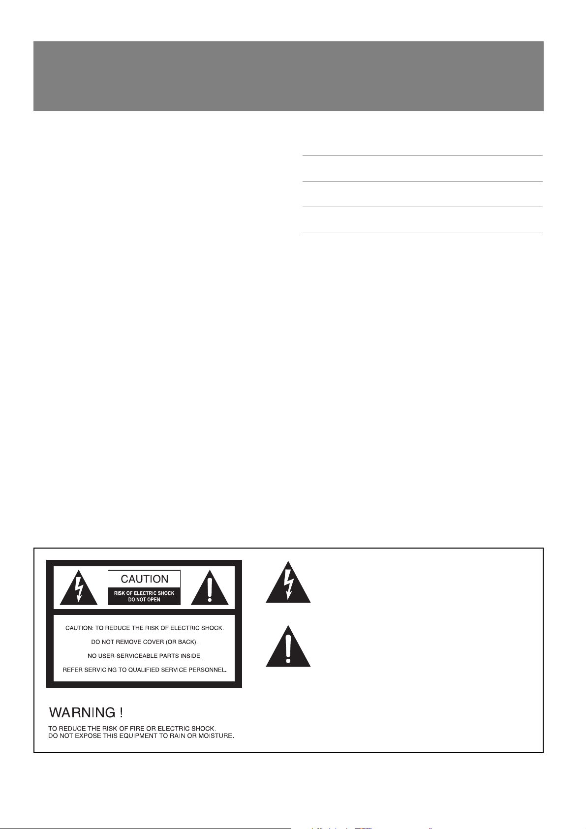
This symbol is intended to alert the user to the presence
of uninsulated “dangerous voltage” within the product’s
enclosure that may be of sufficient magnitude to
constitute a risk of electric shock to persons.
This symbol is intended to alert the user to the presence
of important operation and maintenance (servicing)
instructions in the literature accompanying the appliance.
To prevent electric shock do not use this (polarised) plug
with an extension cord, receptacle or other outlet unless
the blades can be fully inserted to prevent blade exposure.
To prevent electric shock, match wide blade of plug to
wide slot, fully insert.
Caution:
AUS, EUR, USA
Copyright 31st May 2003
Rev A: 31st May 2003
Rev B: 11th Aug 2004
Page 4

PAGE 4 DPRM INSTALLATION & OPERATION MANUAL
CONTROLS
All the controls correspond only to the zone for which the panel
is programmed by the installer. (see programming section)
PROG 1–6
This row of 6 buttons selects the numbered program source.
They are electrically interlocking meaning that selecting one
source will deselect the previously selected source.
PROG OFF
This button will turn off the program source that is
currently selected .
LOCAL ON/OFF
This button toggles the local input on or off.
BUSY
This LED lights when the system network is busy. The remote
control panel is disabled while the system is busy unless it is
the panel in use generating the busy indication.
VOLUME UP/DOWN
These two buttons increase or decrease the volume within
the zone.
TERMINATING
In an RS485 network (of which the DigiPage is part of) it is
important to terminate the last device in the network CAT5 RUN.
A jumper is provided for the data transmission to be terminated
if that Remote Control Panel is at the end of a CAT5 RUN.
Shipped as terminated.
2 3 4 5
1
6
1
2
3
4
5
6
Data
(shown as
terminated)
Holes for
securing cable
Terminal block
for CAT5 wiring
Reset Button
Page 5

DPRM INSTALLATION & OPERATION MANUAL PAGE 5
INSTALLATION
The CAT5 cable connects to the screw terminals numbered 1-6. These
numbers correspond to the pins of the RJ45 connector on the main
unit. If following the 568A convention, the wire colours are wired as:
PIN WIRE COLOUR DP NETWORK
1 White/Green Ground
2 Green +18V
3 White/Orange Data+
4 Blue Busy-
5 White/Blue Busy+ (+18V)
6 Orange Data-
7 White/Brown Spare
8 Brown Spare
Ensure that the spare pair cannot short to anything.
NOTE: If the Remote Control Panel is NOT the last
unit in the CAT5 RUN and there are paging stations
connected further down the run it is important that
the spare pair is continued to the next unit otherwise
voice information from the paging stations will not
get to the main DigiPage unit.
There are two holes available adjacent to the terminal block for
securing the CAT5 cable with a cable tie.
☛
“PIN 1”
Page 6

PAGE 6 DPRM INSTALLATION & OPERATION MANUAL
PROGRAMMING
The following steps are for programming the remote control
panel for use in ZONE X:
Hold down the RESET button on the back.
While holding down the RESET button, hold down both the Up and
Down volume buttons.
Release the RESET button.
The remote control panel will beep 3 times indicating it is in
program mode. The BUSY LED will stay lit while in program mode.
Press the Up button X times (the unit will beep each time).
Eg. for ZONE 4, press 4 times
Press the Down button.
The BUSY LED will go out. The remote control panel is now
programmed.
Confirm that the panel is controlling the correct zone.
NOTE: You have approx. 2 secs to begin the programming
and between button presses else it will exit
programming mode.
☛
1
2
3
4
5
6
7
8
Page 7

Page 8

SYDNEY
(NSW & ACT SALES)
149 Beaconsfield
Street Silverwater
NSW 2128
Private Bag 149
Silverwater NSW 1811
Phone: (02) 9647 1411
Fax: (02) 9648 3698
Email:
nsw@audiotelex.com.au
MELBOURNE
(VIC & TAS SALES)
22/277
Middleborough Road
Box Hill VIC 3128
PO Box 151 Blackburn
South VIC 3130
Phone: (03) 9890 7477
Fax: (03) 9890 7977
Email:
vic@audiotelex.com.au
BRISBANE
(QLD SALES)
42 Commercial Road
Fortitude Valley
QLD 4006
PO Box 871 Fortitude
Valley QLD 4006
Phone: (07) 3852 1312
Fax: (07) 3252 1237
Email:
qld@audiotelex.com.au
ADELAIDE
(SA & NT SALES)
31 Walsh Street
Thebarton
SA 5031
PO Box 157
Hindmarsh SA 5007
Phone: (08) 8352 4444
Fax: (08) 8352 4488
Email:
sa@audiotelex.com.au
PERTH
(WA SALES)
299 Fitzgerald Street
West Perth WA 6005
PO Box 404
North Perth
WA 6906
Phone: (08) 9228 4222
Fax: (08) 9228 4233
Email:
wa@audiotelex.com.au
AUCKLAND
(NZ SALES)
Unit B, 11 Piermark
Drive Albany 1331
New Zealand
PO Box 512
Albany 1331
Phone: (09) 415 9426
Fax: (09) 415 9864
Email:
sales@audiotelex.co.nz
AUSTRALIA AND NEW ZEALAND
www.australianmonitor.com.au
INTERNATIONAL SALES
149 Beaconsfield Street Silverwater NSW 2128 Australia
Private Bag 149 Silverwater NSW 1811
Phone: 61 2 9647 1411
Fax: 61 2 9648 3698
Email: international@audiotelex.com.au
SENNHEISER ELECTRONIC CORPORATION
1 Enterprise Drive
Old Lyme CT 06371 USA
Phone: 1 860 434 9190
Fax: 1 860 434 1759
Email: jalexander@sennheiserusa.com
EUROPE/ASIA/MIDDLE EAST
www.australianmonitor.com.au
USA/SOUTH AMERICA
www.australianmonitor.com
 Loading...