

Page 1
MICRO20/MACRO80P
ACTIVE TWO WAY STEREO SPEAKER SYSTEM
INSTALLATION AND OPERATION MANUAL
Page 2

IMPORTANT SAFETY INFORMATION
1. Save the carton and packing material even if the
equipment has arrived in good condition. Should you ever
need to ship the unit, use only the original factory
packing.
2. Read all documentation before operating your equipment.
Retain all documentation for future reference.
3. Follow all instructions printed on unit chassis for
proper operation.
4. Do not spill water or other liquids into or on the unit,
or operatethe unit while standing in liquid.
5. Make sure power outlets conform to the power
requirements listed on the back of the unit.
6. Do not use the unit if the electrical power cord is frayed
or broken. The power supply cords should be routed so
that they are not likely to be walked on or pinched by
items placed upon or against them, paying particular
attention to cords and plugs, convenience receptacles,
and the point where they exit from the appliance.
7. Always operate the unit with the AC ground wire
connected to the electrical system ground. Precautions
should be taken so that the means of grounding of a piece
of equipment is not defeated.
8. Mains voltage must be correct and the same as that
printed on the rear of the unit. Damage caused by
connection to improper AC voltage is not covered by
any warranty.
14. Do not remove the cover. Removing the cover will expose
you to potentially dangerous voltages. There are no user
serviceable parts inside.
15. Do not drive the inputs with a signal level greater than
that required to drive equipment to full output.
16. Do not connect the inputs / outputs of amplifi ers or
consoles to any other voltage source, such as a battery,
mains source, or power supply, regardless of whether the
amplifi er or console is turned on or off.
17. Do not run the output of any amplifi er channel back into
another channel’s input. Do not parallel- or series-connect
an amplifi er output with any other amplifi er output.
Australian Monitor Inc is not responsible for damage to
loudspeakers for any reason.
18. Do not ground any red (“hot”) terminal. Never connect a
“hot” (red) output to ground or to another “hot” (red)
output!
19. Non-use periods. The power cord of equipment should be
unplugged from the outlet when left unused for a long
period of time.
20. Equipment should be serviced by qualifi ed service
personnel when:
A. The power supply cord or the plug has been damaged.
B. Objects have fallen, or liquid has been spilled into the
equipment
9. Have gain controls on amplifi ers turned down during
power-up to prevent speaker damage if there are high
signal levels at the inputs.
10 Power down & disconnect units from mains voltage
before making connections.
11. Never hold a power switch in the “ON” position if it
won’t stay there itself!
12. Do not use the unit near stoves, heat registers,
radiators, or ther heat producing devices.
13. Do not block fan intake or exhaust ports. Do not operate
equipment on a surface or in an environment which may
impede the normal fl ow of air around the unit, such as a
bed, rug, weathersheet, carpet, or completely enclosed
rack. If the unit is used in an extremely dusty or smoky
environment, the unit should be periodically “blown free”
of foreign matter.
THIS SAFETY INFORMATION IS OF A GENERAL NATURE AND MAY BE SUPPLEMENTED BY INSTRUCTIONS CONTAINED WITHIN THIS MANUAL
C. The equipment has been exposed to rain
D. The equipment does not appear to operate normally, or
exhibits a marked change in performance
E. The equipment has been dropped, or the enclosure
damaged.
Page 3
INTRODUCTION AND CONTENTS
The AMAV Micro20 speakers & Macro80P powered sub woofer
continue to form a compact, yet extremely high quality sub/sat
speaker system. The Micro20 speakers are a sleek design
in die cast aluminium featuring a 3” woofer & 1/2” tweeter
supplied as
a pair, with brackets. The Micro20 speakers are rated at
30 watts RMS & their small size belies their impressive audio
performance.
The Macro80P sub woofer is the perfect partner for the
Micro20P speakers. Featuring dual 6.5” woofers, an onboard
80 watt D class amplifi er for sub frequencies as well as 4 x 20
watt amplifi ers to power Micro20’s, the Macro80P represents
excellent audio reproduction as well as great value for money.
A remote volume, treble & bass control wall plate is also
available for the Macro80P to allow for system control in a
permanent installation.
Congratulations on your purchase of the Micro20/Macro80p
system.
INTRODUCTION 3
REAR PANEL 4
MOUNTING DETAIL 5
SPECIFICATIONS 6
AUS, EUR, USA
REV A: Oct 2007
CAUTION
RISK OF ELECTRIC SHOCK
DO NOT OPEN
CAUTION: TO REDUCE THE RISK OF ELECTRIC SHOCK,
DO NOT REMOVE COVER (OR BACK),
NO USER SERVICEABLE PARTS INSIDE,
REFER SERVICING TO QUALIFIED SERVICE PERSONAL.
WARNING!
TO REDUCE THE RISK OF FIRE OR ELECTRIC SHOCK
DO NOT EXPOSE THIS EQUIPMENT TO RAIN OR MOISTURE.
Caution:
This symbol is intended to alert the user to the presence
of uninsulated “dangerous voltage” within the products
enclosure that may be of suffi cient magnitude to
constitute a risk of electric shock to persons.
This symbol is intended to alert the user to the presence
of important operational and maintenance (servicing)
instructions in the literature accompanying the
appliance.
To prevent electric shock do not use this (polarised) plug
with an extension cord, receptacle or other outlet unless
the blades can be fully inserted to prevent blade exposure.
To prevent electric shock, match wide blade of plug to
wide slot, fully insert.
PAGE 3MICRO20/MACRO80P INSTALLATION & OPERATION MANUAL
Page 4

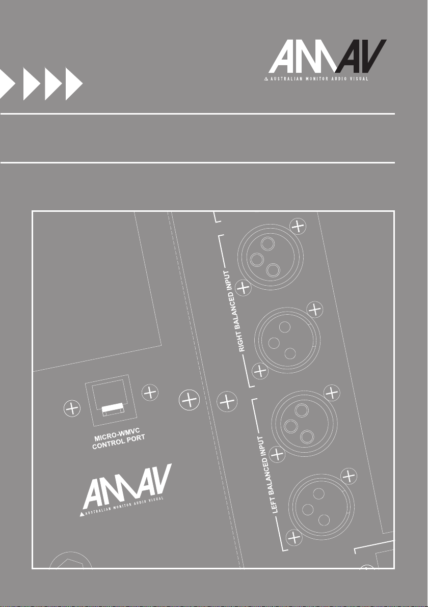
REAR PANEL
MASTER LEVEL CONTROL
10 11
1
This control will set the output
volume for all speakers, including the
level of the sub and the level of all
satellite speakers.
2
SATELLITE LEVEL CONTROL
2
This control will set the output volume
for the satellite speakers. There is
a separate level control for each
satellite output (A, B, C and D) allowing
individual level adjustment for each
12
1
3
9
5
4
6
speaker, within the overall volume
level set by the Master level control.
INPUT
3
The MACRO80P can accept both
balanced and unbalanced stereo line
level inputs.
NOTE: The sub is fed with a
mono summed signal from both
the left and right inputs. The
left signal feeds the A and C
satellite speaker outputs, whilst
the right signal feeds the B and
D satellite speaker outputs.
STEREO/MONO SWITCH
4
This switch can be used to defeat
the stereo capabilities of the speaker
system. When set to “STEREO”, the
left signal will feed the Sub A and C
speakers whilst the right signal will
feed the Sub B and D speakers. When
set to “MONO”, both the left and right
signals are mono summed internally,
allowing signal on either the left or
right inputs to feed all speakers.
7
SPEAKER OUTPUTS
8
5
These outputs are used to connect
the MICRO20 satellite speakers. This
signal is electronically high pass fi ltered at 80Hz. There are four satellite
speaker outputs.
POWER SWITCH
6
This switches the mains power “on”
for the internal amplifi er
POWER INDICATOR
7
This LED illuminates to indicator that
power is available and the Macro80P
is powered on
POWER INLET
8
Standard IEC 230V/10A mains
connection. The Macro80P draws a
maximum current of 1.2 amps. Only
a 250V/2A slow blow fuse should
be used.
WMVC CONTROL PORT
9
Standard RJ45 connector for the
WMVC remote wall mount volume
controller. Connection between the
MACRO80P and WMVC is via a
standard RJ45 CAT5 cable (straight
through, pin to pin).
BASS CONTROL
10
This is a shelf EQ that will cut or
boost the bass frequencies by up to
+/-10dB. This low shelf set to 100Hz.
TREBLE CONTROL
11
This is a shelf EQ that will cut or
boost the treble frequencies by up to
+/-10dB. This high shelf set to 10kHz.
VOLUME CONTROL
12
This control will set the output
volume for the speaker system,
affecting both sub and satellite
speaker level. This level control
is effected by the SATELLITE LEVEL
CONTROL (2) and MASTER LEVEL
CONTROL (1) on the MACRO80P.
PAGE 4 MICRO20/MACRO80P INSTALLATION & OPERATION MANUAL
Page 5

MICRO20 BRACKET MOUNTING DETAIL
MOUNTING DETAIL
WMVC MOUNTING DETAIL
PAGE 5MICRO20/MACRO80P INSTALLATION & OPERATION MANUAL
Page 6

SPECIFICATIONS
MICRO20
WOOFER Diameter 75mm
TWEETER Diameter 25mm
IMPEDANCE 8 ohm
POWER RMS 30W
Program 60W
Peak 120W
SENSITIVITY (1W/1m) 84dB
FREQUENCY RESPONSE (+/-3dB) 140Hz-30kHz
DISPERSION (H X V) 120˚ x 90˚
DIMENSIONS (H X W X D) 150mm x 90mm x 110mm
SHIPPING DIMENSIONS (PAIR) (H X W X D) 190mm x 360mm x 137mm
SHIPPING WEIGHT (PAIR) 4.7kg
PAGE 6 MICRO20/MACRO80P INSTALLATION & OPERATION MANUAL
Page 7

SPECIFICATIONS
MACRO80P
WOOFER Diameter 160mm
POWER RMS 40W
Program 80W
Peak 160W
SENSITIVITY (1W/1m) 90dB
FREQUENCY RESPOSNSE (±3dB) 39Hz-190Hz
SUB POWER OUTPUT 4 ohms, 1% THD, RMS 70W
SATELLITE POWER OUTPUT 8 ohms, 1% THD, RMS 15W
4 ohms, 1% THD, RMS 25W
2 ohms, 1% THD, RMS Not Recommended
SUB BANDPASS 40Hz-175Hz
SATELLITE BANDPASS 80Hz-30kHz
INPUT SENSITIVITY 85mV
CURRENT DRAW 1.2A max
FUSE RATING 250V, 2A, SB
DIMENSIONS (H X W X D) 405mm x 270mm x 345mm
SHIPPING DIMENSIONS (H X W X D) 500mm x 410mm x 360mm
SHIPPING WEIGHT 15.7kg
WMVC
EQ CONTROLS Bass 100Hz ±10dB
Treble 10kHz, ±10dB
MAX CABLING DISTANCE 50m
DIMENSIONS (H X W X D) 115mm x 75mm x 44mm
SHIPPING DIMENSIONS (H X W X D) 80mm x 130mm x 85mm
SHIPPING WEIGHT 0.2kg
PAGE 7MICRO20/MACRO80P INSTALLATION & OPERATION MANUAL
Page 8

AUSTRALIA AND NEW ZEALAND
www.australianmonitor.com.au
SYDNEY
(NSW & ACT SALES)
1 Clyde Street
Silverwater
NSW 2128
Private Bag 149
Silverwater NSW 1811
Phone: (02) 9647 1411
Fax: (02) 9648 3698
Email:
nsw@audiotelex.com.au
MELBOURNE
(VIC & TAS SALES)
22/277
Middleborough Road
Box Hill VIC 3128
PO Box 151 Blackburn
South VIC 3130
Phone: (03) 9890 7477
Fax: (03) 9890 7977
Email:
vic@audiotelex.com.au
BRISBANE
(QLD SALES)
42 Commercial Road
Fortitude Valley
QLD 4006
PO Box 871 Fortitude
Valley QLD 4006
Phone: (07) 3852 1312
Fax: (07) 3252 1237
Email:
qld@audiotelex.com.au
EUROPE / ASIA / MIDDLE EAST
www.australianmonitor.com.au
INTERNATIONAL SALES
1 Clyde Street Silverwater NSW 2128 Australia
Private Bag 149 Silverwater NSW 1811
Phone: (02) 9647 1411
Fax: (02) 9648 3698
Email:
international@audiotelex.com.au
ADELAIDE
(SA & NT SALES)
31 Walsh Street
Thebarton
SA 5031
PO Box 157
Hindmarsh SA 5007
Phone: (08) 8352 4444
Fax: (08) 8352 4488
Email:
sa@audiotelex.com.au
PERTH
(WA SALES)
3/11 Howe Street
Osborne Park WA 6017
PO Box 1281
Osborne Park
BC WA 6916
Phone: (08) 9204 0200
Fax: (08) 9244 3738
Email:
wa@audiotelex.com.au
AUCKLAND
(NZ SALES)
9C Piermark Drive
Albany 0752
New Zealand
PO Box 300-512
Albany 0752
Phone: (09) 415 9426
Fax: (09) 415 9864
Email:
sales@audiotelex.co.nz
 Loading...