


 Loading...
ADDITIONS & UPDATES
23RD July 2012
UPDATE
Easier wiring for rear amber blinkers.
1st December 2010
ADDITIONS
BN1 Front wheel Timken bearings.
A70 Head - Fitting.
Hazard flasher system.
Finding TDC.
Recolour traficator head.
S.U. Carby notes. 100 Threads. UPDATES
Amber rear flashers
Alternator – Fitting.
Alternator Wide fan belt.
Wiring Diagram in colour.
100 TECHNICAL CD-ROM
INTRODUCTION
This CD is a compilation of articles I have found, been given or written, which are specifically for 100's, or are of a general nature that may be of interest to 100 owners. Every owner whether they are concourse, runner or modifier types should be able to find something of interest, there are over 480 pages so you have a lot of reading ahead of you.
I would like to thank Barry Campbell, Chris Dimmock, John Dowsett, John Harper and Ian Howard for permission to include their articles.
Barry’s articles were published in Flat Chat (The Monthly Magazine of the Austin Healey Owner’s Club of NSW (Inc) Australia.), similarly with Chris Dimmock’s, John Dowsett’s and Ian Howard’s. John Harper’s were published in Rev Counter the magazine of one of the English Clubs. Internet Downloads are from various websites. My articles are either titled Real Healey Natter (published in Flat Chat) or 100 Technical (this is their first publication).
The Austin Service Bulletins are from the collection of the Late Bill Johnstone and I would like to thank Margaret and Scott Johnstone for supplying them.
John Harper's Disclaimer - “Whilst every effort is made to check the information incorporated in this series, no responsibility can be accepted for errors” - should also be taken to apply to all the articles.
© The copyrights of articles remain with the authors.
FOURS FOR EVER DON HARDIE
healeynut@hotmail.com
P.S.
I haven’t tried all these ideas, so let me know if the ones you try work or don’t.

REAL HEALEY NATTER
100 ENGINE AND CHASSIS Nos. OCTOBER 1997
A perusal of the just received Year Book showed that the 100 in front of me, and the one behind but one, on the assembly line at Longbridge are alive and well (?) and living in Western Australia.
A list was drawn up of all BN1's with chassis numbers beginning with 224 to see if anything else stood out, but all that was obvious was that there a lot of numberless cars on the states lists and South Australia showed only the Model. If any one can find some pattern or has a comment to make please send it to the Editor for Publication.
What stood out to me was that I am the only one without an original engine.
DAVID MOULD................... |
N.S.W................. |
BN1/224020 ................. |
1B224020M |
ANDREW NOBLE ............... |
VIC. .................... |
BN1/224322 ................. |
|
RUSSELL SEDUNARY........ |
N.S.W................. |
BN2/224323 ................. |
1B224323 |
JOSEPH HOMSEY............... |
VIC. .................... |
BN1/224315 ................. |
1B224315 |
PETER RUTZOU.................. |
VIC. .................... |
BN1/224328 ................. |
1B224328M |
NOEL GORN ....................... |
W.A. ................... |
BN1/224438 ................. |
1B24438M |
DMH 000 ............................. |
N.S.W. ................ |
BN1/224439................. |
1B219055M |
PETER TENNANT............... |
W.A. ................... |
BN1/224441 ................. |
1B224441 |
MAL BROWN ...................... |
W.A. ................... |
BN1/224441? ............... |
|
IAN HANCOCK .................. |
N.S.W................. |
BN1/224446 ................. |
B224446 |
KENNETH STYLES............. |
VIC. .................... |
BN1/224696 ................. |
H1B224696 |
RICHARD BRAY ................. |
N.S.W................. |
BN1/224588 ................. |
1B224588 |
DON STEVENS ................... |
W.A. ................... |
BN1/224894 ................. |
H1B224894M |
DMH-000
(The Hardie's 100)
P.S. I don't know how a BN2 and two 224441's got in there, but I suspect Gremlins were helping the list makers.
PAGE 1 OF 1

INTERNET DOWNLOAD
LE MANS CONVERSION KIT
100 M PARTS LIST
PAGE 1 OF 3

PAGE 2 OF 3
.

Downloaded from www.acmefluid.com.au/larry/
PAGE 3 0F 3
100 THREADS
The parts of the 100 that Donald Healey designed were all UNF because this thread by that date had become the British standard. However Austin designed parts, going back in a few cases to before W.W.II, were BSF.
Therefore the engine BN1 gearbox, spiral bevel rear axle, suspension and hubs etc. were BSF.
All chassis parts including such things as the grease nipples were UNF
When BMC introduced onto the 100 the Hypoid rear axle, the BN2 gearbox, the BN2 front suspension and hubs they had UNF threads, these major units having been designed for the A90 Westminster after W.W.II.
If one uses this simple guide it will hold good for about 99% of all cases.
It is also worth noting that some early Austin parts have B.A. threads. These were replaced later with 10-32 UNC threads.
JOHN HARPER’S ARTICLES
No 5
A70 and 2.2 Litre Engines
Simon Tyrrell's article on page 43 of the August 1990 Rev Counter has raised some interesting questions which will no doubt provoke many readers to put pen to paper and send in their contributions to Rev Counter. In anticipation of this I have produced my own input whilst the subject is "topical".
My first comment on Simon's article is that it is not just the A70 engine, which is worth considering, but the whole four-cylinder petrol range from the Austin 16 right through to the 2.2 litre used in taxis and commercial vehicles. It is also well worth including the 2. 5 litre which was the last application of our family of engines used in the rather mundane EA van (engine type 25U). This variant was mounted 'under floor' tilted over on its left (manifold) side by 55 degrees.
There were many changes to the later engines, the major one being the crankshaft, which had a completely different flywheel flange with a conventional oil seal. The main difference in the cylinder block, other than the bore size, between these engines and the type used on the 100 was the lack of the tachometer drive assembly. I know of an A90 Atlantic fitted with an A70 engine, which has got around this problem by using an electronic, positive earth rev counter fitted into the mechanical case so as to blend with the rest of the instruments.
I personally doubt whether there is enough metal in the 2.2 litre cylinder wall to bore it out much past the maximum .060 inch oversize. To make the bore the same as a standard 100 would equate to an oversize of .3125 inches, over five times the recommended maximum! I have tried to measure the wall thickness on both engines with the core plugs removed. Although this is difficult to measure accurately the wall thicknesses do seem to be about the same. I for one would not risk going much beyond the maximum recommendation. One might, however, just get away with boring a 2.5 litre block out to 2.6 litre standard size but no more because this is now .0975 inch oversize. The height of the 100 pistons will need to be checked in the 2.5 litre block.
I doubt whether it is worth the risk in effort and expense of trying to fit a sleeve into a cracked block.
The question of using Rover V8 pistons has come up before but I have not been able to trace the source of the suggestion. Some initial, investigations have shown that the diameter is .61 inch larger than the 100 against the maximum recommended oversize of
.040 inches. It in shorter and will not reach the top of the bore by about one eighth of an inch. The bowl is a slightly different shape and detailed calculations are needed to see whether a satisfactory compression ratio can be achieved and whether the high compression ones used in the V8 saloons or the low compression used in 'the Range Rover are the best. There are only three rings on the Rover piston against 4 or 5 on the 100 and the gudgeon pin in slightly different.
Page 1 of 3
JOHN HARPER’S ARTICLES
No 5
Again a personal view, I would not fit valve inserts purely for running "lead free'.
The 100 head is particularly prone to cracking across the valve seats and good cylinder heads are in short supply. The extra pressure created by a tightly fitted seat is likely to increase the risk of cracking and the insert could become loose and cause major damage. If a seat is badly worn then an insert may be the only answer, but I would recommend "cutting back" the seat if at all possible before resorting to this.
I have two friends who have run their cars with an unmodified A70 head. The Only thing to watch is that a later WA-XSTAT type of thermostat with a small diameter bulb
is used. The larger bellows type will not always go in because it is fitted in a housing mounted on top) of the head on an A70.
One of these cars per forms well against other 100's on the track. The owner of the other has managed to obtain a correct head, which is now fitted. The change that he noticed was not to the performance as one might expect, but in the smoothness of running. It is not necessary to skim anything off the head as the compression ratio with the A70 head is reasonable at approximately 8: 1 against the standard 7,5: 1. In Geoffrey Healey's book, AUSTIN HEALEY he describes on PAGE 232 an experiment made with an A70 engine which was dropped because it was more fussy and “not liked". Perhaps we have experienced something similar here!
The push rods that Simon refers to are almost: certainly the hydraulic versions fitted co the early Austin 16. 1 drove one of these for about four years and after the initial rattle when cold they made for a very quiet engine. They worked by allowing the oil pressure in the rocker shaft and rockers to enter the push rod through an oil way drilled through the centre of the push rod top cup. This filled the push rod with oil and made it 'solid". The slight oil leakage allowed the push rod to shorten slowly as the components changed temperature. They were replaced I believe on cost grounds and occasional failure due to blockage caused by dirty oil. As an interesting experiment this type of push rod could be fitted to a 100 if they were shortened to match the later valve gear. The engine would run quieter and tappet adjustment would be eliminated.
Page 2 of 3
JOHN HARPER’S ARTICLES
No 5
In conclusion Simon is right to point out that there are many useful parts to be obtained from 2.2 litre engines, but these need to be checked carefully before use because of all the
minor changes and improvements that took place.
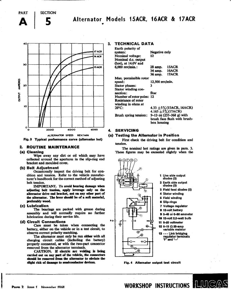
Fan Belt & Dynamo Pulley Size
The length of the fan belt is fairly critical as at one extreme the dynamo is up tight against the cylinder block and at the other the dynamo fan could cut into the top hose particularly if this is fitted a bit too low.
One problem sometimes Met is that a slightly larger pulley has been fitted from an Austin A70 or early A90. This in itself will not cause a problem but a slightly longer belt may be needed.
The two pulley sizes are 3 5/8' and 4 1/8" inches diameter. The larger one has two holes for a special puller. The smaller, correct one has to be pulled on the flange and can easily be broken, as it is a brittle casting.
The original BMC part number for the belt: is 2H 4238, but the most readily obtainable and best fit replacement is the Ferodo V150 with the following dimensions:
Outside Circumference 47.4 inches,
Inside Circumference 47.3 inches
Top Width |
0.75 |
Thickness |
0.5 |
Angle 32 degrees inclusive
A near equivalent, and sometimes recommended alternative, is the Ferodo V104 with an O.C. of 46.1”. This is rather tight: and may need the dynamo to be partly removed to fit it.
Other equivalents are; Mintex TK 474 or Romac C738
But I recommend checking these for size before attempting to fit.
DISCLAIMER: Whilst every effort is made to check the information incorporated in this series, no responsibility can be accepted for errors. However, corrections, improvements, suggestions & additional information will be very welcome (in writing please).
COPYRIGHT: This is held by the author. This article therefore may not be copied or republished without his permission. To contact the author please write to him at: 7 Cedar Avenue, Ickleford, Hitchin, Herts. SG5 3XU. or
Telephone 0462-51970.
Page 3 of 3
A70 HEAD
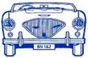
The A70 head is narrower than the Healey one and has to be built up with weld to cover the water passages in the block adjoining each cylinder.
Mine was built up with a MIG Welder by John Dowsett (a NSW Club Member) who runs Classic Connections at Riverstone a restoration business specialising in Austin Healeys.
I cleaned up the welds on the sides to make them look nice and had the head surface ground to get the new welded sections level with the rest of the face of the head. I then extended the water passages in the head to line up with those in the block and gasket. It’s not an easy job but a lot cheaper than an alloy head.
The combustion chambers are smaller because of the A70’s 2.2 litre capacity, this raises the compression ratio. I don’t know what this ratio is now, but I have to use 98 octane petrol to stop running on.
At No 4 cylinder a crack developed and I had it fixed by MG Metalock a company at Bankstown, who drill holes along the crack and fit threaded plugs (no welding). No 2 Cylinder has now got a similar crack (you can see the rust in the 3rd picture) and I will soon have to get that fixed.
The modified A70 head has now done abt 50,000 miles and the repair was done abt 30,000 miles ago when the engine was rebuilt, hardened exhaust valve seats and Chev valves fitted for unleaded petrol.
Don Hardie 09 03 2009
Page 1 of 3

After 14 ½ years and 58,509 miles after the welding, the second was repaired by Metalock Australia at Ingleburn, the pictures below shows how. (D.H. 31/10/2009)
Page 2 of 3
First crack repaired 1999
Second crack repaired 2009
You can see how the water holes had to be extended to match up with the Head Gasket, which would have a source of a leak, as the original Healey head was prone to leaking at these points with full coverage out to the edge of the gasket.
Page 3 of 3

REAL HEALEY NATTER
FITTING A LUCAS 18ACR ALTERNATOR
Back in 1996 I returned from the South Coast via the Princes Highway after dark. As all know Lucas (The Prince of Darkness) headlights are not their best on dark country roads. When I joined the Hardie Household I was presented with a pair of Cibe Quartz headlight units fitted with 120/80-watt globes and powered through a twin relay. Things were a lot brighter but this resulted in the ammeter showing a discharge when the drain of those two 120 watt high beams was combined with tail lights, dash lights, ignition, fuel pump and some times windscreen wipers and heater. This meant that the 22amp generator had reached its maximum charge rate, thus couldn't keep the system voltage up to scratch resulting in the lights not running to their full potential. Neil Dunn had mentioned to Barry Campbell, some time ago, that running the generator at full charge for extended periods could result in it throwing the solder out of the commutator joints, so after many years of procrastination, I insisted on an alternator being fitted.
First change the electrical system to NEGATIVE EARTH if it is still Positive to Earth. See relevant article.
The fitting a narrow fan belt had already been done (see relevant article) and a 45amp Lucas 18ACR, with built in regulator, was purchased from my friendly Wrecker (sorry - Auto Parts Recycler) and painted engine green. The stiffener strip welded across the generator bracket had to be removed, but with less strain and vibration from the narrow belt it is figured that this should be ok, but it will be closely watched for any problem. The alternator was secured to the bracket by a 7 1/2" length of 5/16" threaded rod and two pieces of 5/16" ID stainless steel tube of suitable length. The original adjusting linkage was used and with the fan belt fitted and everything tightened, SURPRISE, the pulleys lined up exactly.
See the Wide Belt Alternator article if to still have one.
The Hardies 100
Page 1 of 5

THE WIRING WAS UPDATED 28/06/2010
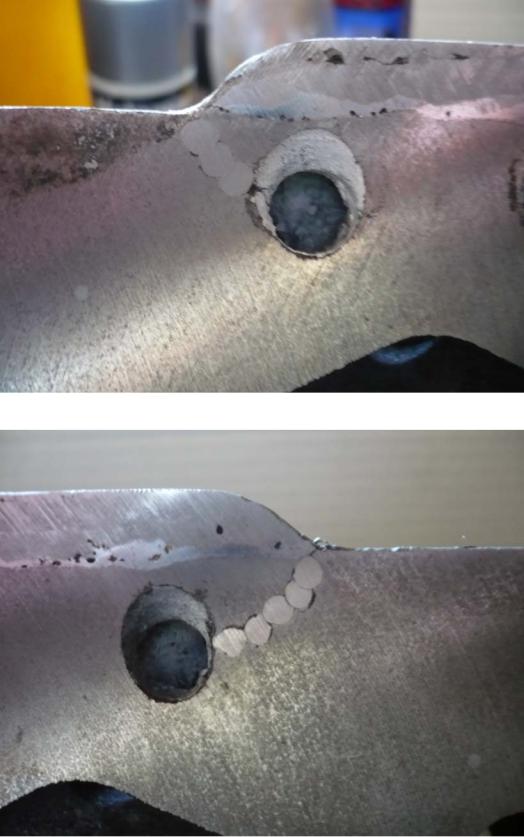
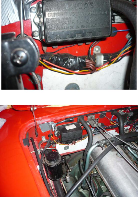
The way I first wired up the alternator in 1996 was rather clumsy so I changed it. The existing generator wires are now connected to the alternator, the yellow to one of the large spade terminals and the yellow/green to the small lower spade terminal, I connected another wire from the other large spade terminal to the headlight relays mounted on the right hand inner guard. The relays originally had a wire up to the regulator, and I left it connected, so there are now two wires supplying current to the regulator, which is now only used as a junction box.
There was an old regulator in the “precious spares” bin, so all its innards were removed leaving the copper and steel strips underneath intact and two pieces of 20 amp wire stripped of their insulation were soldered across them all, except the earth terminal (the one on the right of the photo below).
Page 2 of 5
This was then mounted in place of the original and all the wires connected to the four left hand terminals, except the yellow/green and small yellow (the ignition light wires), which were both connected to the right hand one (the old earth one).
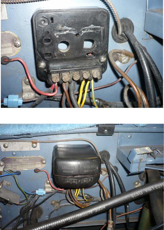
From above the regulator box is still there and the changes in the wiring are hard to see.
Page 3 of 5
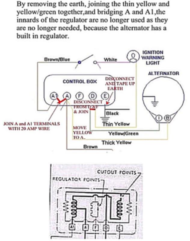
USING THE REGULATOR WITHOUT MODIFICATION
IGNITION
SWITCH
Page 4 of 5
Another way of doing it, the wires are joined with electrical connectors, wrapped in electrical tape and secured with plastic ties.
From above the regulator box is still there and the changes in the wiring are hard to see.
Don Hardie 28/06/2010
Page 5 of 5
100 TECH 09
WIDE BELT ALTERNATOR
In a discussion with Brad Robinson about fitting an alternator where the wide fan belt is still fitted, he mentioned that he had seen an alternator with a split pulley (i.e.- the pulley is made in two parts) and by spacing the parts apart with washers, it can be made to fit a 100’s wide fan belt. I don’t know if he pursued this, but what follows is how I have done it since.
ALTERNATOR
These come in many different types so we will concentrate on Bosch ones, make sure the one you get is the split pulley type i.e. the pulley is made up of two identical steel pressings NOT the cast iron type. If you can’t get the split type pulley you can part the cast iron pulley, in the centre of the “V” on a lathe, into two pieces. Space out the outer pulley side to fit the wide belt, if you can’t refit the spring washer use ‘Loctite’.
It might also be an idea to check the carbon brushes in the regulator (new ones can be purchased from most Auto Electricians) and fit new bearings as the load of the wide belt could be greater than that of the narrow one.
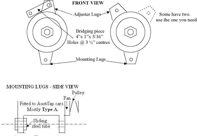
Mounting and adjusting lugs are of a couple of different types the front views are shown below -
Page 1 of 2

CHANGES TO EXISTING GENERATOR BRACKET
Remove the stiffener strip welded across the generator bracket. Secure the alternator to the bracket by a 7 1/2" length of 5/16" threaded rod and two pieces of 5/16" ID stainless steel tube of suitable length.
Keep an eye on the generator bracket as the wide belt may put more strain and vibration on it.
For wiring see the article “ALTERNATOR – FITTING”, the Bosch alternators have a spade terminal to fit the yellow/green wire to and a threaded terminal with a nut for the yellow wire.
Page 2 of 2


Subject: Aluminum door finishers
How do you get the finish back on the Aluminium door finishers?
Jim
Use #00 or #000 steel wool, with a medium touch, takes time. Finish with clear, (flat / semigloss), rattle can paint. The clear will dull the shiny alu after steel wool.
I have parked next to concourse cars, hard to tell the difffff.
Kirk Kvam
Adjusting the firmness of Armstrong lever shock absorbers |
http://home.comcast.net/~rhodes/shock.html |
Armstrong lever arm shocks are available in a variety of damping grades. The variations are made primarily in the valving. The way these devices work is that there are two pistons pushing oil back and forth through an orifice. This orifice is small, so there is resistance to flow due
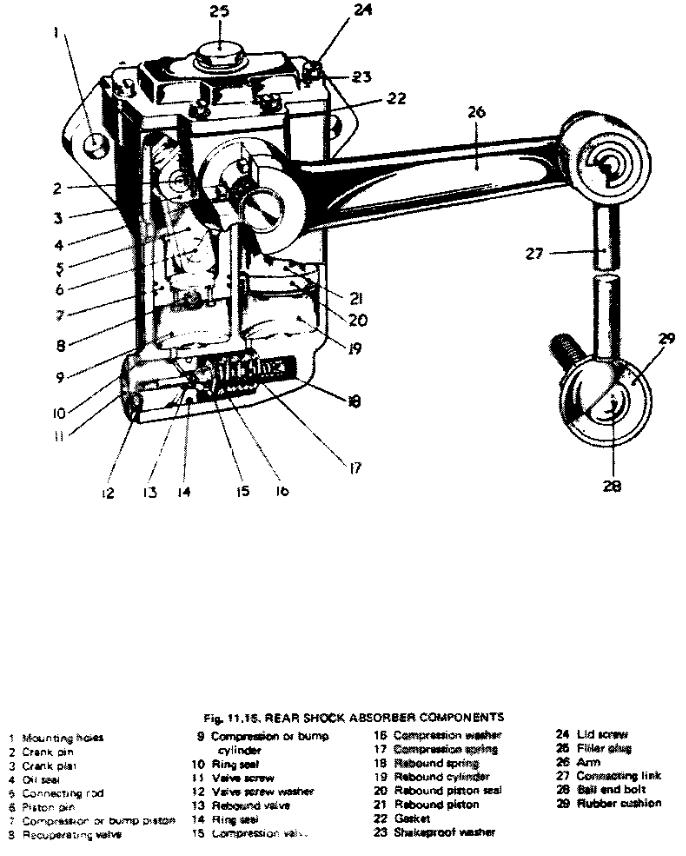
to the viscosity of the oil in the piston chambers. If the size of the connecting hole was not allowed to vary, the damping would be VERY strong for sudden jolts. It would be so strongly damped that it would be rigid for all practical purposes. In order to accomodate sudden jolts, the oil is allowed to force its way past the small orifice through a larger spring-loaded valve. There are actually two separate valves in the valve assembly. One to control the upward jolts (bounce)(#13 in the diagram) and another to control the downward return of the suspension to its rest position (#15).
The springs (#17,18) adjust the damping. When these units were new, there were alternate compression springs available. Kastner said that certain shocks had as standard a steel (grey) colored compression spring, but other shocks
had a bright copper colored spring as standard. Mine have the bright copper springs. The "competition" spring has a dull copper or bronze color. I have seen none
of these competition springs available nor do I know the various spring strengths to try to get new ones. There are "heavy duty" valve assemblies
for certain cars, but none that I know of for the TR's, and I doubt that they are completely interchangeable.
In order to adjust damping today, we can tighten the nut holding the rebound spring and insert spacers (washers)under the compression spring. I have two sources that pretty much agree on what modifications to make. First use 30wt oil for the hydraulic fluid (Kastner recommended 40wt). Next adjust the springs. I have been told to use Harley-Davidson fork oil
because engine oil has detergents which will damage the rubber seals, and the
fork oil has anti-foaming additives to cut down foam when stressed to the max. You have to use H-D oils because the others use stuff that is maximum 20wt.
My first source says to tighten the nut on the rebound spring "all the way down", and install a 0.070" spacer under the compression spring at the bottom of the bore.
My other source says to tighten the nut on the rebound spring 2 to 4 full turns, and a spacer of 0.040" to 0.080" under the compression spring. Select the amount of adjustment depending on how much damping you want. I decided to try settings near the maximum and ease off from there if they were too harsh or if there was some other problem.
My experience is limited, but successful. I tightened the rebound spring nut
by 4 turns (which is almost all the way down). I used 2 brass washers under each compression spring. The washers were obtained from my local hardware store for about 15 cents each. They measured just over 1/2" diameter and 0.038" thickness. I used a file to smooth and slightly thin the washers. I had to ream the center holes large enough to easily pass the rebound spring. The four washers were matched in pairs and I got 0.073" combined thickness on each side. The outer diameter of the washers was 0.563", and the inner diameter was 0.322".
I have found that the damping is quite nice. I am using the TriumphTune 4212 rear springs (420 lbs/inch and about stock ride height). This
combination seems very satisfactory. Good damping without being harsh. Total cost for the upgrade: $4.95 for a pint of "heavy duty" (about 30wt) fork oil and about $1.50 for the washers.
Let me know your experiences!
Back to HOME
1 of 2 |
25/12/2008 5:11 PM |
Adjusting the firmness of Armstrong lever shock absorbers |
http://home.comcast.net/~rhodes/shock.html |
2 of 2 |
25/12/2008 5:11 PM |

REAL HEALEY NATTER
SEPTEMBER 1995
AUSTIN LINEAGE
The current issue of BMW Australia's Magazine has an article "Where have all the badges gone", which looks at all the marques that BMW acquired when they bought Rover.
The lineage of the current Rover company reads like War and Peace ie:- Austin Rover, British Leyland, British Motor Holdings, Leyland, Rover, Alvis, Triumph, Standard, BMC, Austin, Vanden Plas, Morris, Wolseley, Riley, MG etc.
The article starts with a double page spread of the Unipart sponsored red 2754DK with the caption "Very British: The Austin Healey 3000 was one of the most popular sports cars of its time, made for "real men" only."
Other extracts are as follows:-
"... Suffice to say that numerous members of the fairer sex have long been seriously flirting with those mean machines of yesteryear,"
"The history of Rover reads like Liz Taylor's catalogue of spouses."
"Names like Austin Healey, MG or Triumph evoke very different associations (from Rover and Land Rover - DMH).
The air begins to vibrate, tyres squeal, petrol gets into the blood stream: we are talking about hot-blooded tarmac-burners, an all out driving experience, the ultimate joys of motoring."
"Austin Healey, MG and Triumph were fierce rivals right into the sixties."
"... the big Austin Healeys belonged to the exclusive luxury car sector."
"The "Big Healeys" meanwhile, were proving powerful but highly unpredictable ..."
"Top international rally drivers dubbed them "The Pig"."
"The very first BMW was an the Austin Seven built under licence." (1928 –Don H)
"BMW is going to help Rover assert itself as an independent marque."
Page 1 of 2
Loading...